Quantcast
Channel: SparkFun Tutorials
Viewing all 1123 articles
Browse latest View live

SparkFun Inventor's Kit Experiment Guide - v4.1

$
0
0

SparkFun Inventor's Kit Experiment Guide - v4.1 a learn.sparkfun.com tutorial

Available online at: http://sfe.io/t891

Introduction

Please note that this tutorial is for the SparkFun Inventor's Kit version 4.1 If you have SIK v3.3 or are using parts from the add-on pack, please refer to this tutorial.

The SparkFun Inventor's Kit (SIK) is your map for navigating the waters of beginning embedded electronics. This guide contains all the information you will need to build five projects encompassing the 16 circuits of the SIK. At the center of this guide is one core philosophy: that anyone can (and should) play around with electronics. When you’re done with this guide, you will have built five projects and acquired the know-how to create countless more. Now enough talk — let’s start something!

Choosing a Kit

If you need a overview of the parts included in your kit, please click on the product link below.

SparkFun Inventor's Kit - v4.1

SparkFun Inventor's Kit - v4.1

KIT-15267
$99.95

The primary difference between the two kits is the microcontroller included in the kit. The SparkFun Inventor's Kit includes a SparkFun RedBoard Qwiic. At the heart of each is the ATmega328p microcontroller, giving both the same functionality underneath the hood. Both development boards are capable of taking inputs (such as the push of a button or a reading from a light sensor) and interpreting that information to control various outputs (like a blinking LED light or an electric motor). And much, much more!

Note: You can complete all 16 experiments in this guide with either kit.

If you need more information to determine which microcontroller is right for you, please check out the following tutorials.

What is an Arduino?

February 26, 2013

What is this 'Arduino' thing anyway?

RedBoard Qwiic Hookup Guide

January 10, 2019

This tutorial covers the basic functionality of the RedBoard Qwiic. This tutorial also covers how to get started blinking an LED and using the Qwiic system.

Open Source!

At SparkFun, our engineers and educators have been improving this kit and coming up with new experiments for a long time now. We would like to give attribution to Oomlout, since we originally started working off their Arduino Kit material many years ago. The Oomlut version is licensed under the Creative Commons Attribution Share-Alike 3.0 Unported License.

The SparkFun Inventor's Kit V4.1 is licensed under the Creative Commons Attribution Share-Alike 4.0 International License.

Baseplate Assembly

Before you can build circuits, you'll want to first assemble the breadboard baseplate. This apparatus makes circuit building easier by keeping the breadboard and the RedBoard microcontroller connected together without the worry of disconnecting or damaging your circuit. The larger the circuit, the more wires needed to build it. The more wires there are, the easier it is for one of those wires to come undone.

To begin, grab all the parts: the RedBoard, the breadbaord, the included screwdriver, the baseplate and the two baseplate screws.

Baseplate1 of parts laid out

If the screwdriver end is a flathead screwdriver, pull the shaft out, rotate it around to the Phillips head screwdriver side, and reinsert the shaft.

Next, peel the adhesive backing off the breadboard.

Baseplate2

Carefully align the breadboard over its spot on the baseplate. The text on the breadboard should face the same direction as the text on the baseplate. Firmly press the breadboard to the baseplate to adhere it.

Baseplate3

Align the RedBoard with its spot on the baseplate. The text on it should face the same direction as the text on the breadboard and the baseplate. Grab on of the two included screws, and firmly screw it into one of the four stand-off holes found on the RedBoard. The plastic holes are not threaded, so you will need to apply pressure as you twist the screwdriver.

Baseplate4 screwing the board in

Screw the second screw in the stand-off hole diagonally across from the first. With that, your baseplate is now assembled.

Baseplate5 assembled Base Plate

Arduino Uno Baseplate Assembly

Newer versions of the Arduino Uno come with a clear, plastic baseplate of their own. It will need to be removed before the Uno can be attached to the breadboard baseplate. To remove it, pull it from the Uno.

Uno

You may now attach the Uno to the baseplate as shown in the instructions above.

Uno on baseplate
Please Note: The Arduino Uno and the SparkFun RedBoard are pin-for-pin identical. Though the circuits in this guide show the SparkFun RedBoard, the Arduino Uno can be interchanged and used with all the same circuit diagrams and hookup tables. All the pin names and locations are the same on both development platforms.

The SparkFun RedBoard Qwiic

The SparkFun RedBoard Qwiic is your development platform. At its roots, the RedBoard is essentially a small, portable computer, also known as a microcontroller. It is capable of taking inputs (such as the push of a button or a reading from a light sensor) and interpreting that information to control various outputs (like blinking an LED light or spinning an electric motor). That’s where the term “physical computing” comes in; this board is capable of taking the world of electronics and relating it to the physical world in a real and tangible way.

The SparkFun RedBoard is one of a multitude of development boards based on the ATmega328 microprocessor. It has 14 digital input/output pins (six of which can be PWM outputs), six analog inputs, a 16MHz crystal oscillator, a USB connection, a power jack, and a reset button. You’ll learn more about each of the RedBoard's features as you progress through this guide.

Check out the guide below to learn more about the SparkFun RedBoard Qwiic.

RedBoard Qwiic Hookup Guide

January 10, 2019

This tutorial covers the basic functionality of the RedBoard Qwiic. This tutorial also covers how to get started blinking an LED and using the Qwiic system.

Understanding Breadboards

A breadboard is a circuit-building platform that allows you to connect multiple components without using a soldering iron.

If you have never seen or used a breadboard before, it is highly recommended you read the following guide that explains the breadboards anatomy and how to use one.


How to Use a Breadboard

May 14, 2013

Welcome to the wonderful world of breadboards. Here we will learn what a breadboard is and how to use one to build your very first circuit.


Install the Arduino IDE and SIK Code

The following steps are a basic overview of getting started with the Arduino IDE. For more detailed, step-by-step instructions for setting up the Arduino IDE on your computer, please check out the following tutorial.

Installing Arduino IDE

March 26, 2013

A step-by-step guide to installing and testing the Arduino software on Windows, Mac, and Linux.

Download the Arduino IDE

In order to get your microcontroller up and running, you'll need to download the newest version of the Arduino software first (it's free and open source!).

This software, known as the Arduino IDE, will allow you to program the board to do exactly what you want. It’s like a word processor for writing code.

Download Arduino Example Code

You are so close to to being done with setup! Download the SIK Guide Code. You can also download the code from GitHub or click the following link to download the code:

Place the SIK-Guide-Code folder in the Arduino IDE examples directory:

  • Windows: drag the SIK-Guide-Code-V4.1 folder into C:\Program Files\Arduino-x\examples

  • MacOS: Right-click on the Arduino IDE app and click "Show Package Contents...". Drag the SIK-Guide-Code-V4.1 folder into Contents/Resources/Java
  • Linux: see http://www.arduino.cc/playground/Learning/Linux

Install the CH340 Drivers

The drivers for the CH340C might be pre-installed on Windows, Mac, and Linux. However, there are a wide range of operating systems and versions out there so we recommend installing the drivers to ensure that they work properly. Please go to How to Install CH340 Drivers for specific instructions on how to install the CH340C drivers with your RedBoard Qwiic.

New!

How to Install CH340 Drivers

August 6, 2019

How to install CH340 drivers (if you need them) on Windows, Mac OS X, and Linux.

Connect the Microcontroller to Your Computer

Use the USB cable provided in the SIK kit to connect the included microcontroller (RedBoard or Arduino Uno) to one of your computer’s USB inputs.

Select Your Board: Arduino/Genuino Uno

Before we can start jumping into the experiments, there are a couple adjustments we need to make. This step is required to tell the Arduino IDE which of the many Arduino boards we have. Go up to the Tools menu. Then hover over Board and make sure Arduino Uno is selected.

Please note: Your SparkFun RedBoard and the Arduino UNO are interchangeable but you won’t find the RedBoard listed in the Arduino Software. Select “Arduino/Genuino Uno” instead.

Select a Serial Port

Next up we need to tell the Arduino IDE which of our computer's serial ports the microcontroller is connected to. For this, again go up to Tools, then hover over Port (Serial Port in older Arduino versions) and select your RedBoard or Arduino's serial port. This will be the same serial port seen when installing CH340 drivers.

With that, you're now ready to begin building your first circuit!

Project 1: Light

Welcome to your first SparkFun Inventor's Kit project. Each project is broken up into several circuits, each designed to help you learn about new technologies and concepts. The knowledge gained from each circuit will play a part in building each project. This first project will set the foundation for the rest of the projects in the guide and will aid in helping you understand the basic fundamentals of circuit building and electricity!

In Project 1, you will learn about light-emitting diodes (LEDs), resistors, inputs and sensors --- using all of those technologies to build and program your own multicolored night-light! The night-light uses a sensor to turn on an RGB (Red, Green, Blue) LED when it gets dark, and you will be able to change the color using an input knob.

Project 1

New Components Introduced in This Project

Each of the components listed below will be described in more detail as you progress through each project.

  • LEDs
  • Resistors
  • Potentiometers
  • Photoresistors

New Concepts Introduced in This Project

Each of the concepts listed below will be described in more detail as you progress through each project.

  • Polarity
  • Ohm's Law
  • Digital Output
  • Analog vs. Digital
  • Analog Input
  • Analog to Digital Conversion
  • Voltage Divider
  • Pulse-width Modulation
  • Functions

You Will Learn

  • How to upload a program to your RedBoard or Arduino Uno
  • Circuit building basics
  • How to control LEDs with digital outputs
  • How to read sensors you analog inputs

Light-Emitting Diodes, or LEDs (pronounced el-ee-dees), are small, powerful lights that are used in many different applications. You can find LEDs in just about any source of light nowadays, from the bulbs lighting your home to the tiny status lights flashing on your home electronics. Blinking an LED is the classic starting point for learning how to program embedded electronics. It's the "Hello, World!" of microcontrollers.

In this circuit, you’ll write code that makes an LED flash on and off. This will teach you how to build a circuit, write a short program and upload that program to your RedBoard.

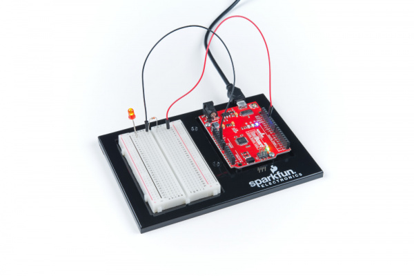
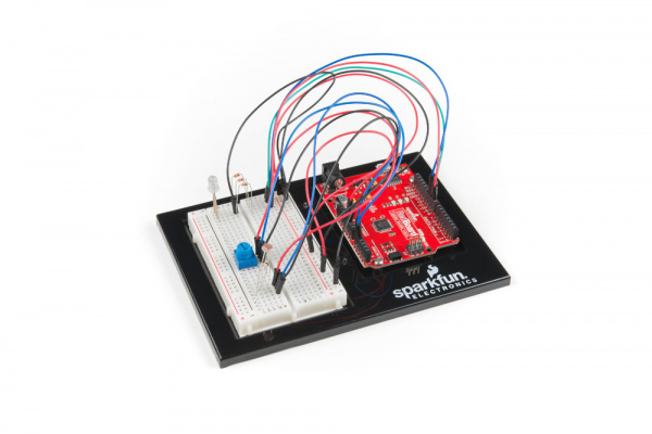
Circuit 1A Hero Shot

Parts Needed

Grab the following quantities of each part listed to build this circuit:

parts

New Components and Concepts: Each circuit will introduce new components or parts that will be used in the circuit. Each circuit will also introduce a few new concepts that will help you understand what your circuit and code is doing and why.

New Components

LED (Light Emitting Diode)

Light-Emitting Diodes (LEDs) are small lights made from a silicon diode. They come in different colors, brightnesses and sizes. LEDs have a positive (+) leg and a negative (-) leg, and they will only let electricity flow through them in one direction. LEDs can also burn out if too much electricity flows through them, so you should always use a resistor to limit the current when you wire an LED into a circuit.

LED

Resistors

Resistors resist the flow of electricity. You can use them to protect sensitive components like LEDs. The strength of a resistor (measured in ohms) is marked on the body of the resistor using small colored bands. Each color stands for a number, which you can look up using a resistor chart.

Resistors

New Concepts

Polarity

Many electronics components have polarity, meaning electricity can only flow through them in one direction. Components like resistors do not have polarity; electricity can flow through them in either direction. However, components like an LED that do have polarity only work when electricity flows through them in one direction.

Ohm's Law

Ohm's law describes the relationship between the three fundamental elements of electricity: voltage, resistance and current. This relationship can be represented by the following equation:

Ohm's Law

Where

  • V = Voltage in volts
  • I = Current in amps
  • R = Resistance in ohms (Ω)

This equation is used to calculate what resistor values are suitable to sufficiently limit the current flowing to the LED so that it does not get too hot and burn out.

Digital Output

When working with microcontrollers such as the RedBoard, there are a variety of pins to which you can connect electronic components. Knowing which pins perform which functions is important when building your circuit. In this circuit, we will be using what is known as a digital output. There are 14 of these pins found on the RedBoard and Arduino Uno. A digital output only has two states: ON or OFF. These two states can also be thought of as HIGH or LOW or TRUE or FALSE. When an LED is connected to one of these pins, the pin can only perform two jobs: turning the LED on and turning the LED off. We'll explore the other pins and their functions in later circuits.

Digital Pins

The 14 digital pins highlighted.

Hardware Hookup

We recommend familiarizing yourself with each of the components used in each circuit first.

Polarized Components Pay special attention to the component’s markings indicating how to place it on the breadboard. Polarized components can only be connected to a circuit in one direction.

**Pay close attention to the LED. It is polarized. The negative side of the LED is the short leg, marked with a flat edge. **

LED drawing

Components like resistors need to have their legs bent into 90° angles in order to correctly fit the breadboard sockets.

330Ohm Resistor Bent

Ready to start hooking everything up? Check out the circuit diagram and hookup table below, to see how everything is connected.

Circuit Diagram

Circuit Diagrams: SparkFun uses a program called Fritzing to draw the circuit diagrams you see throughout this guide and throughout all of our online guides. Fritzing allows us to create diagrams that make it easier for you to see how your circuit should be built.

Circuit 1A Fritzing

Having a hard time seeing the circuit? Click on the image for a closer look.

Hookup Table

Hookup Tables: Many electronics beginners find it helps to have a coordinate system when building their circuits. For each circuit, you'll find a hookup table that lists the coordinates of each component and where it connects to the RedBoard, the breadboard, or both. The breadboard has a letter/number coordinate system, just like the game Battleship.
ComponentRedBoardBreadboardBreadboard
LED A1 LED ( - )A2 LED ( + )
330Ω Resistor
(orange, orange, brown)
E2F2
Jumper WireGNDE1
Jumper WireDigital Pin 13J2

In the table, polarized components are shown with a warning triangle and the whole row highlighted yellow.

Open Your First Sketch

Open the Arduino IDE software on your computer. Open the code for Circuit 1A by accessing the SIK Guide Code you downloaded and placed into your examples folder earlier.

To open the code, go to: File > Examples > SIK_Guide_Code-V_4 > SIK_Circuit_1A-Blink

Experiment_List

You can also copy and paste the following code into the Arduino IDE. Hit upload, and see what happens!

language:cpp
/*
SparkFun Inventor’s Kit
Circuit 1A-Blink

Turns an LED connected to pin 13 on and off. Repeats forever.

This sketch was written by SparkFun Electronics, with lots of help from the Arduino community.
This code is completely free for any use.

View circuit diagram and instructions at: https://learn.sparkfun.com/tutorials/sparkfun-inventors-kit-experiment-guide---v40
Download code at: https://github.com/sparkfun/SIK-Guide-Code
*/

void setup() {

pinMode(13, OUTPUT);      // Set pin 13 to output

}


void loop() {

digitalWrite(13, HIGH);   // Turn on the LED

delay(2000);              // Wait for two seconds

digitalWrite(13, LOW);    // Turn off the LED

delay(2000);              // Wait for two seconds

}

What You Should See

The LED will flash on for two seconds, off for two seconds, then repeat. If it doesn't, make sure you have assembled the circuit correctly and verified and uploaded the code to your board, or see the Troubleshooting section at the end of this section.

Circuit 1A action shot

Program Overview

  1. Turn the LED on by sending power to Pin 13.
  2. Wait 2 seconds (2000 milliseconds).
  3. Turn the LED off by cutting power to Pin 13.
  4. Wait 2 seconds (2000 milliseconds).
  5. Repeat.

One of the best ways to understand the code you just uploaded is to change something and see how it affects the behavior of your circuit. For this first circuit, try changing the number found in these lines of code: delay(2000);. What happens if you change both to 100? What happens if you change both to 5000? What happens if you change just one delay and not the other?

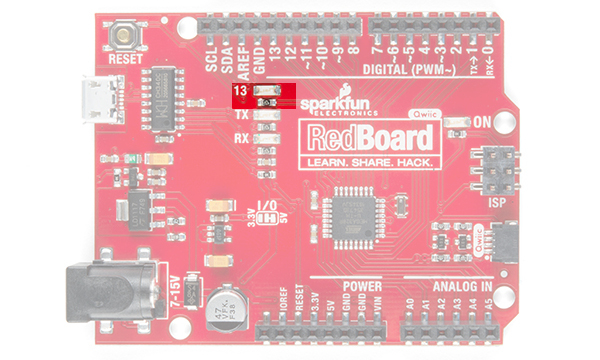
Onboard LED PIN 13: You may have noticed a second, smaller LED blinking in unison with the LED in your breadboard circuit. This is known as the onboard LED, and you can find one on almost any Arduino or Arduino-compatible board including the RedBoard. In most cases, this LED is connected to digital pin 13 (D13), which is the same pin used in this circuit. This LED is useful for troubleshooting, as you can always upload the Blink sketch to see if that LED lights up. If so, you know your board is functioning properly. If you do not want this LED to blink with other LEDs in your circuits, simply use any of the other 12 digital pins (D0-D12).

Code to Note

Code to Note: The sketches that accompany each circuit introduce new programming techniques and concepts as you progress through the guide. The Code to Note section highlights specific lines of code from the sketch and explains them in further detail.
CodeDescription
Setup and Loop:
void setup(){code to run once}&void loop(){code to run forever}
Every Arduino program needs these two functions. Code that goes in between the curly brackets of setup() runs once, then the code in between the loop() curly brackets runs over and over until the RedBoard is reset or powered off.
Input or Output?:
pinMode(13, OUTPUT);
Before you can use one of the digital pins, you need to tell the RedBoard whether it is an INPUT or OUTPUT. We use a built-in "function" called pinMode() to make pin 13 a digital output. You'll learn more about digital inputs in Project 2.
Digital Output:
digitalWrite(13, HIGH);
When you're using a pin as an OUTPUT, you can command it to be HIGH (output 5 volts) or LOW (output 0 volts).
Delay:
delay(time in milliseconds);
Causes the program to wait on this line of code for the amount of time in between the brackets. After the time has passed, the program will continue to the next line of code.
Comments:
//This is a comment
Comments are a great way to leave notes in your code explaining why you wrote it the way you did. You'll find many comments in the examples that further explain what the code is doing and why. Comments can be single line using //, or they can be multi-line using /* */.

Coding Challenges

Coding Challenges: The Coding Challenges section is where you can find suggestions for changes to the circuit or code that will make the circuit more challenging. If you feel underwhelmed by the tasks in each circuit, visit the Coding Challenges section to push yourself to the next level.
ChallengeDescription
Persistence of VisionComputer screens, movies and the lights in your house all flicker so quickly that they appear to be on all of the time but are actually blinking faster than the human eye can detect. See how much you can decrease the delay time in your program before the light appears to be on all the time but is still blinking.
Morse CodeTry changing the delays and adding more digitalWrite() commands to make your program blink a message in Morse code.

Troubleshooting

Troubleshooting: Last, each circuit has a Troubleshooting section with helpful tips and tricks to aid you in any problems you encounter along the way.
ProblemSolution
I get an error when uploading my codeThe most likely cause is that you have the wrong board selected in the Arduino IDE. Make sure you have selected Tools > Board > Arduino/Genuino Uno.
I still get an error when uploading my codeIf you're sure you have the correct Board selected but you still can't upload, check that you have selected the correct Serial Port. You can change this in Tools > Serial Port >your_serial_port.
Which Serial Port is the right one?Depending on how many devices you have plugged into your computer, you may have several active Serial Ports. Make sure you are selecting the correct one. A simple way to determine this is to look at your list of Serial Ports. Unplug your RedBoard from your computer. Look at the list again. Whichever Serial Port has disappeared from the list is the one you want to select once you plug your board back in to your computer.
My code uploads, but my LED won’t turn onLEDs will only work in one direction. Try taking it out of your breadboard, turning it 180 degrees, and reinserting it.
Still not working?Jumper wires unfortunately can go "bad" from getting bent too much. The copper wire inside can break, leaving an open connection in your circuit. If you are certain that your circuit is wired correctly and that your code is error-free and uploaded but you are still encountering issues, try replacing one or more of the jumper wires for the component that is not working.

Circuit 1B: Potentiometer

Potentiometers (also known as “pots” or “knobs”) are one of the basic inputs for electronics devices. By tracking the position of the knob with your RedBoard, you can make volume controls, speed controls, angle sensors and a ton of other useful inputs for your projects. In this circuit, you'll use a potentiometer as an input device to control the speed at which your LED blinks.

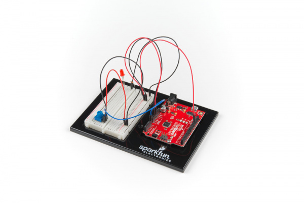
Project1 Circuit1B Potentiometer

Parts Needed

Grab the following quantities of each part listed to build this circuit:

parts

New Components

Potentiometer

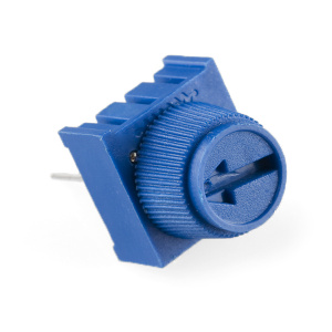
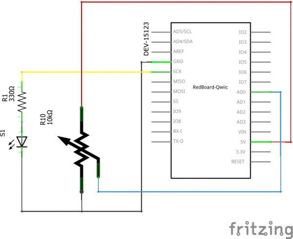
A potentiometer (trimpot for short) is a variable resistor. When powered with 5V, the middle pin outputs a voltage between 0V and 5V, depending on the position of the knob on the potentiometer. Internal to the trimpot is a single resistor and a wiper, which cuts the resistor in two and moves to adjust the ratio between both halves. Externally, there are usually three pins: two pins connect to each end of the resistor, while the third connects to the pot's wiper.

potentiometer

New Concepts

Analog vs. Digital

Understanding the difference between analog and digital is a fundamental concept in electronics.

We live in an analog world. There is an infinite number of colors to paint an object (even if the difference is indiscernible to our eye), an infinite number of tones we can hear, and an infinite number of smells we can smell. The common theme among all of these analog signals is their infinite possibilities.

Digital signals deal in the realm of the discrete or finite, meaning there is a limited set of values they can be. The LED from the previous circuit had only two states it could exist in, ON or OFF, when connected to a Digital Output.

Analog Inputs

So far, we've only dealt with outputs. The RedBoard also has inputs. Both inputs and outputs can be analog or digital. Based on our definition of analog and digital above, that means an analog input can sense a wide range of values versus a digital input, which can only sense two states.

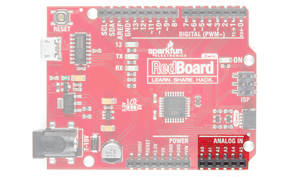
You may have noticed some pins labeled Digital and some labeled Analog In on your RedBoard. There are only six pins that function as analog inputs; they are labeled A0--A5.

analog pins vs digital pins

The six analog pins highlighted.

Voltage Divider

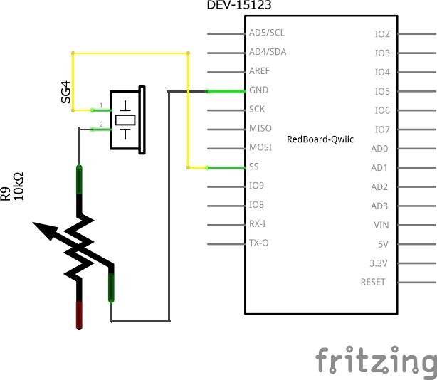
A voltage divider is a simple circuit that turns some voltage into a smaller voltage using two resistors. The following is a schematic of the voltage divider circuit. Schematics are a universally agreed upon set of symbols that engineers use to represent electric circuits.

voltage divider

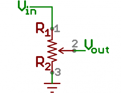
A potentiometer is a variable resistor that can be used to create an adjustable voltage divider.

Schematic symbol for a potentiometer

A potentiometer schematic symbol where pins 1 and 3 are the resistor ends, and pin 2 connects to the wiper

If the outside pins connect to a voltage source (one to ground, the other to Vin), the output (Vout) at the middle pin will mimic a voltage divider. Turn the trimpot all the way in one direction, and the voltage may be zero; turned to the other side, the output voltage approaches the input. A wiper in the middle position means the output voltage will be half of the input.

Voltage dividers will be covered in more detail in the next circuit.

Hardware Hookup

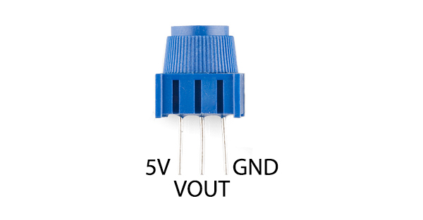
The potentiometer has three legs. Pay close attention into which pins you're inserting it on the breadboard, as they will be hard to see once inserted.

Potentiometers are not polarized. You can attach either of the outside pins to 5V and the opposite to GND. However, the values you get out of the trimpot will change based on which pin is 5V and which is GND.

potentiometer_pinout

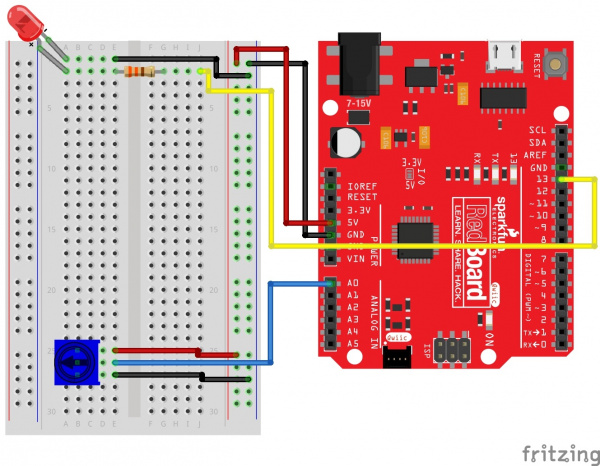
Ready to start hooking everything up? Check out the circuit diagram and hookup table below to see how everything is connected.

Circuit Diagram

Circuit 1B Fritzing

Having a hard time seeing the circuit? Click on the image for a closer look.

Hookup Table

ComponentRedBoardBreadboardBreadboardBreadboard
Jumper Wire5V5V Rail ( + )
Jumper WireGNDGND Rail ( - )
LED A1 LED ( - )A2 LED ( + )
330Ω Resistor
(orange, orange, brown)
E2F2
Jumper WireE1GND Rail ( - )
Jumper WireDigital Pin 13J2
PotentiometerB25B26B27
Jumper WireAnalog Pin 0 (A0)E26
Jumper WireE255V Rail ( + )
Jumper WireE27GND Rail ( - )

In the table, polarized components are shown with a warning triangle and the whole row highlighted yellow.

Open the Sketch

To open the code, go to: File > Examples > SIK_Guide_Code-V_4 > SIK_Circuit_1B-Potentiometer

You can also copy and paste the following code into the Arduino IDE. Hit upload, and see what happens!

language:cpp
/*
SparkFun Inventor’s Kit
Circuit 1B-Potentiometer

Changes how fast an LED connected to pin 13 blinks, based on a potentiometer connected to pin A0

This sketch was written by SparkFun Electronics, with lots of help from the Arduino community.
This code is completely free for any use.

View circuit diagram and instructions at: https://learn.sparkfun.com/tutorials/sparkfun-inventors-kit-experiment-guide---v40
Download code at: https://github.com/sparkfun/SIK-Guide-Code
*/

int potPosition;       //this variable will hold a value based on the position of the potentiometer

void setup()
{
  Serial.begin(9600);       //start a serial connection with the computer

  pinMode(13, OUTPUT);      //set pin 13 as an output that can be set to HIGH or LOW
}

void loop()
{
  //read the position of the pot
  potPosition = analogRead(A0);    //set potPosition to a number between 0 and 1023 based on how far the knob is turned
  Serial.println(potPosition);     //print the value of potPosition in the serial monitor on the computer

  //change the LED blink speed based on the trimpot value
  digitalWrite(13, HIGH);           // Turn on the LED
  delay(potPosition);              // delay for as many milliseconds as potPosition (0-1023)

  digitalWrite(13, LOW);            // Turn off the LED
  delay(potPosition);              // delay for as many milliseconds as potPosition (0-1023)
}

What You Should See

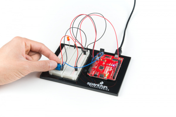
You should see the LED blink faster or slower in accordance with your potentiometer. The delay between each flash will change based on the position of the knob. If it isn't working, make sure you have assembled the circuit correctly and verified and uploaded the code to your board, or see the Troubleshooting section.

circuit 1B action shot

Program Overview

  1. Read the position of the potentiometer (from 0 to 1023) and store it in the variable potPosition.
  2. Turn the LED on.
  3. Wait from 0 to 1023 milliseconds, based on the position of the knob and the value of potPosition.
  4. Turn the LED off.
  5. Wait from 0 to 1023 milliseconds, based on the position of the knob and the value of potPosition.
  6. Repeat.
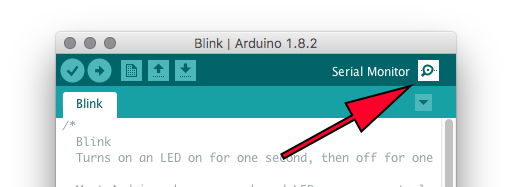
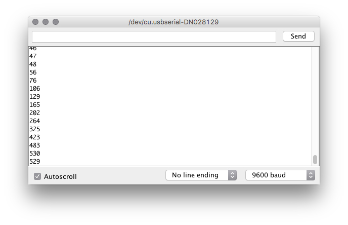
The Serial Monitor: The Serial Monitor is one of the Arduino IDE's many great built-in tools. It can help you understand the values that your program is trying to work with, and it can be a powerful debugging tool when you run into issues where your code is not behaving the way you expected it to. This circuit introduces you to the Serial Monitor by showing you how to print the values from your potentiometer to it. To see these values, click the Serial Monitor button, found in the upper-right corner of the IDE in most recent versions. You can also select Tools > Serial Monitor from the menu.

You should then see numeric values print out on the monitor. Turn the potentiometer, and you should see the values change as well as the delay between each print.


If you are having trouble seeing the values, ensure that you have selected 9600 baud in the dropdown menu and have auto scroll checked.

Code to Note

CodeDescription
Integer Variables:
int potPosition;
A variable is a placeholder for values that may change in your code. You must introduce, or "declare" variables before you use them. Here we're declaring a variable called potPosition of type int (integer). We will cover more types of variables in later circuits. Don't forget that variable names are case-sensitive!
Serial Begin:
Serial.begin(9600);
Serial commands can be used to send and receive data from your computer. This line of code tells the RedBoard that we want to "begin" that communication with the computer, the same way we would say "Hi" to initiate a conversation. Notice that the baud rate, 9600, is the same as the one we selected in the monitor. This is the speed at which the two devices communicate, and it must match on both sides.
Analog Input:
potPosition = analogRead(A0);
We use the analogRead() function to read the value on an analog pin. analogRead() takes one parameter, the analog pin you want to use, A0 in this case, and returns a number between 0 (0 volts) and 1023 (5 volts), which is then assigned to the variable potPosition.
Serial Print:
Serial.println(potPosition);
This is the line that actually prints the trimpot value to the monitor. It takes the variable potPosition and prints whatever value it equals at that moment in the loop(). The ln at the end of print tells the monitor to print a new line at the end of each value; otherwise the values would all run together on one line. Try removing the ln to see what happens.

Coding Challenges

ChallengeDescription
Changing the RangeTry multiplying, dividing or adding to your sensor reading so that you can change the range of the delay in your code. For example, can you multiply the sensor reading so that the delay goes from 0–2046 instead of 0–1023?
Adding More LEDsAdd more LEDs to your circuit. Don't forget the current limiting resistor for each one. Try making multiple LEDs blink at different rates by changing the range of each using multiplication or division.

Troubleshooting

ProblemSolution
The potentiometer always reads as 0 or 1023Make sure that your 5V, A0 and GND pins are properly connected to the three pins on your potentiometer. It is easy to misalign a wire with the actual trimpot pin.
No values in Serial MonitorMake sure that you have selected the correct baud rate, 9600. Also ensure that you are on the correct Serial Port. The same Serial Port you use when uploading code to your board is the same Serial Port you use to print values to the Serial Monitor.

Circuit 1C: Photoresistor

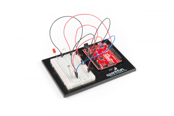
In circuit 1B, you got to use a potentiometer, which varies resistance based on the twisting of a knob. In this circuit you’ll be using a photoresistor, which changes resistance based on how much light the sensor receives. Using this sensor you can make a simple night-light that turns on when the room gets dark and turns off when it is bright.

Project1 Circuit 1C Photoresistor

Parts Needed

Grab the following quantities of each part listed to build this circuit:

parts

New Components

Photoresistor

Photoresistors, or photocells, are light-sensitive, variable resistors. As more light shines on the sensor’s head, the resistance between its two terminals decreases. They’re an easy-to-use component in projects that require ambient-light sensing.

Photoresistor

New Concepts

Analog to Digital Conversion

The world we live in is analog, but the RedBoard lives in a digital world. In order to have the RedBoard sense analog signals, we must first pass them through an Analog to Digital Converter (or ADC). The six analog inputs (A0--A5) covered in the last circuit all use an ADC. These pins "sample" the analog signal and create a digital signal for the microcontroller to interpret. The "resolution" of this signal is based on the resolution of the ADC. In the case of the RedBoard, that resolution is 10-bit. With a 10-bit ADC, we get 2 ^ 10 = 1024 possible values, which is why the analog signal varies between 0 and 1023.

Voltage Divider Continued

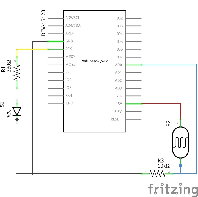
Since the RedBoard can’t directly interpret resistance (rather, it reads voltage), we need to use a voltage divider to use our photoresistor, a part that doesn't output voltage. The resistance of the photoresistor changes as it gets darker or lighter. That changes the amount of voltage that is read on the analog pin, which "divides" the voltage, 5V in this case. That divided voltage is then read on the analog to digital converter.
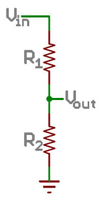
Left: A regular voltage divider circuit. Vout will be a constant voltage. Right: A variable voltage divider circuit. Vout will fluctuate as the resistance of the photoresistor changes.

The voltage divider equation assumes that you know three values of the above circuit: the input voltage (Vin), and both resistor values (R1 and R2). Given those values, we can use this equation to find the output voltage (Vout):

Vout = Vin * (R2 / (R1 + R2))

If R1 is a constant value (the resistor) and R2 fluctuates (the photoresistor), the amount of voltage measured on the Vout pin will also fluctuate.

Hardware Hookup

Note that the photoresistor is not polarized. It can be inserted in either direction.

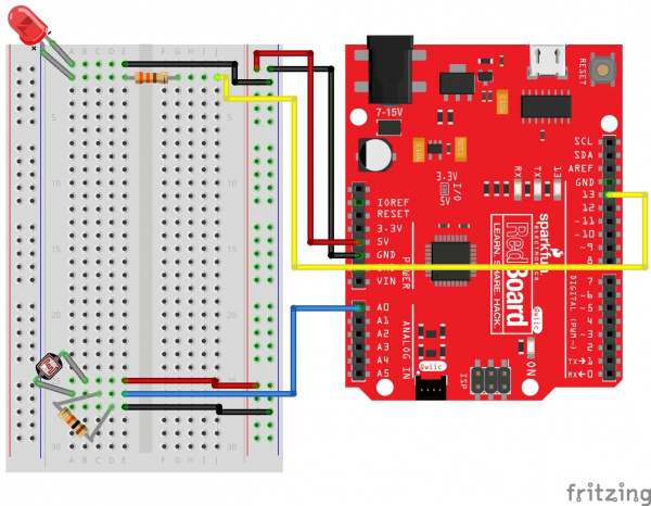
Ready to start hooking everything up? Check out the circuit diagram and hookup table below to see how everything is connected.

Circuit Diagram

Circuit 1C Fritzing Diagram

Having a hard time seeing the circuit? Click on the image for a closer look.

Hookup Table

ComponentRedBoardBreadboardBreadboard
Jumper Wire5V5V Rail ( + )
Jumper WireGNDGND Rail ( - )
LED A1 LED ( - )A2 LED ( + )
330Ω Resistor
(orange, orange, brown)
E2F2
Jumper WireE1GND Rail ( - )
Jumper WireDigital Pin 13J2
PhotoresistorA26B25
10kΩ Resistor
(brown, black, orange)
C26D27
Jumper WireAnalog Pin 0 (A0)E26
Jumper WireE255V Rail ( + )
Jumper WireE27GND Rail ( - )

In the table, polarized components are shown with a warning triangle and the whole row highlighted yellow.

Open the Sketch

To open the code, go to: File > Examples > SIK_Guide_Code-V_4 > SIK_Circuit_1C-Photoresistor

You can also copy and paste the following code into the Arduino IDE. Hit upload, and see what happens!

language:cpp
/*
SparkFun Inventor’s Kit
Circuit 1C-Photoresistor

Use a photoresistor to monitor how bright a room is, and turn an LED on when it gets dark.

This sketch was written by SparkFun Electronics, with lots of help from the Arduino community.
This code is completely free for any use.

View circuit diagram and instructions at: https://learn.sparkfun.com/tutorials/sparkfun-inventors-kit-experiment-guide---v40
Download drawings and code at: https://github.com/sparkfun/SIK-Guide-Code
*/

int photoresistor = 0;              //this variable will hold a value based on the brightness of the ambient light
int threshold = 750;                //if the photoresistor reading is below this value the light will turn on

void setup()
{
  Serial.begin(9600);               //start a serial connection with the computer

  pinMode(13, OUTPUT);              //set pin 13 as an output that can be set to HIGH or LOW
}

void loop()
{
  //read the brightness of the ambient light
  photoresistor = analogRead(A0);   //set photoresistor to a number between 0 and 1023 based on how bright the ambient light is
  Serial.println(photoresistor);    //print the value of photoresistor in the serial monitor on the computer

  //if the photoresistor value is below the threshold turn the light on, otherwise turn it off
  if (photoresistor < threshold){
    digitalWrite(13, HIGH);         // Turn on the LED  
  } else{
    digitalWrite(13, LOW);          // Turn off the LED
  }

  delay(100);                       //short delay to make the printout easier to read
}

What You Should See

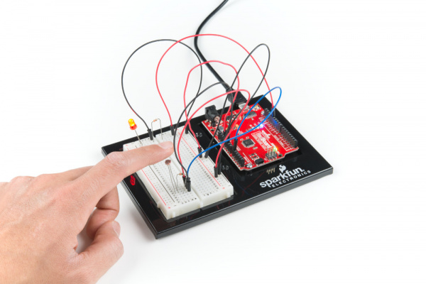
The program stores the light level in a variable, photoresistor. Then, using an if/else statement, the program checks to see what it should do with the LED. If the variable is above the threshold (it’s bright), turn the LED off. If the variable is below the threshold (it’s dark), turn the LED on. You now have just built your own night-light!

Project1 Circuit1C Action

Open the Serial Monitor in Arduino. The value of the photoresistor should be printed every so often. When the photoresistor value drops below the threshold value set in the code, the LED should turn on (you can cover the photoresistor with your finger to make the value drop).

Note: If the room you are in is very bright or dark, you may have to change the value of the “threshold” variable in the code to make your night-light turn on and off. See the Troubleshooting section for instructions.

Program Overview

  1. Store the light level in the variable photoresistor.
  2. If the value of photoresistor is above the threshold (it’s bright), turn the LED off.
  3. If the value of photoresistor is below the threshold (it’s dark), turn the LED on.

Code to Note

CodeDescription
If/else Statements:
if(logic statement) {
code to be run if the logic statement is true}
else {
code to be run if the logic statement is false }
The if/else statement lets your code react to the world by running one set of code when the logic statement in the round brackets is true and another set of code when the logic statement is false. For example, this sketch uses an if statement to turn the LED on when it is dark, and turn the LED off when it is light.
Logical Operators:
(photoresistor < threshold)
Programmers use logic statements to translate things that happen in the real world into code. Logic statements use logical operators such as 'equal to' (==), 'greater than' (>), and 'less than' (<), to make comparisons. When the comparison is true (e.g., 4 < 5) then the logic statement is true. When the comparison is false (e.g., 5 < 4) then the logic statement is false. This example is asking whether the variable photoresistor is less than the variable threshold.

Coding Challenges

ChallengeDescription
Response PatternRight now your if statement turns the LED on when it gets dark, but you can also use the light sensor like a no-touch button. Try using digitalWrite() and delay() to make the LED blink a pattern when the light level drops, then calibrate the threshold variable in the code so that the blink pattern triggers when you wave your hand over the sensor.
Replace 10K&ohm; Resistor with LEDAlter the circuit be replacing the 10K&ohm; resistor with an LED (the negative leg should connect to GND). Now what happens when you place your finger over the photoresistor? This is a great way to see Ohm's law in action by visualizing the change in resistance's affect on the current flowing through the LED.

Troubleshooting

ProblemSolution
The light never turns on or always stays onStart the Serial Monitor in Arduino. Look at the value that the photoresistor is reading in a bright room (e.g., 915). Cover the photoresistor, or turn the lights off. Then look at the new value that the photoresistor is reading (e.g., 550). Set the threshold in between these two numbers (e.g., 700) so that the reading is above the threshold when the lights are on and below the threshold when the lights are off.
Nothing is printing in the Serial MonitorTry unplugging your USB cable and plugging it back in. In the Arduino IDE, go to Tools > Port, and make sure that you select the right port.

Circuit 1D: RGB Night-Light

In this circuit, you'll take the night-light concept to the next level by adding an RGB LED, which is three differently colored Light-Emitting Diodes (LEDs) built into one component. RGB stands for Red, Green and Blue, and these three colors can be combined to create any color of the rainbow!

Project1 Circuit1D

Parts Needed

Grab the following quantities of each part listed to build this circuit:

parts

New Components

RGB LED

An RGB LED is actually three small LEDs --- one red, one green and one blue --- inside a normal LED housing. The RGB LED included in this kit has all the internal LEDs share the same ground wire, so there are four legs in total. To turn one color on, ensure ground is connected, then power one of the legs just as you would a regular LED. If you turn on more than one color at a time, you will see the colors start to blend together to form a new color.

RGB LED

New Concepts

Analog Output (Pulse-width Modulation)

You can use the digitalWrite() command to turn pins on the RedBoard on (5V) or off (0V), but what if you want to output 2.5V? The RedBoard doesn't have an Analog Output, but it is really good at switching some digital pins on and off fast enough to simulate an analog output. analogWrite() can output 2.5 volts by quickly switching a pin on and off so that the pin is only on 50 percent of the time (50% of 5V is 2.5V). By changing the percent of time that a pin is on, from 0 percent (always off) to 100 percent (always on), analogWrite() can output any voltage between 0 and 5V. This is what is known as pulse-width modulation (or PWM). By using PWM, you can create many different colors with the RGB LED.

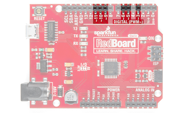
Digital (PWM~): Only a few of the pins on the RedBoard have the circuitry needed to turn on and off fast enough for PWM. These are pins 3, 5, 6, 9, 10 and 11. Each PWM pin is marked with a ~ on the board. Remember, you can only use analogWrite() on these pins.

Creating Your Own Simple Functions

When programmers want to use a piece of code over and over again, they write a function. The simplest functions are just chunks of code that you give a name to. When you want to run that code, you can “call” the function by typing its name, instead of writing out all of the code. More complicated functions take and return pieces of information from the program (we call these pieces of information parameters). In this circuit, you'll write functions to turn the RGB LED different colors by just typing that color's name.

Hardware Hookup

Polarized Components Pay special attention to the component’s markings indicating how to place it on the breadboard. Polarized components can only be connected to a circuit in one direction.

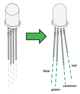
Just like a regular LED, an RGB LED is polarized and only allows electricity to flow in one direction. Pay close attention to the flat edge and to the different length leads. Both are indicators to help orient the LED correctly.

RGB LED Pins

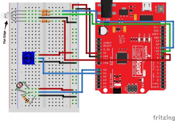
Ready to start hooking everything up? Check out the circuit diagram and hookup table below to see how everything is connected.

Circuit Diagram

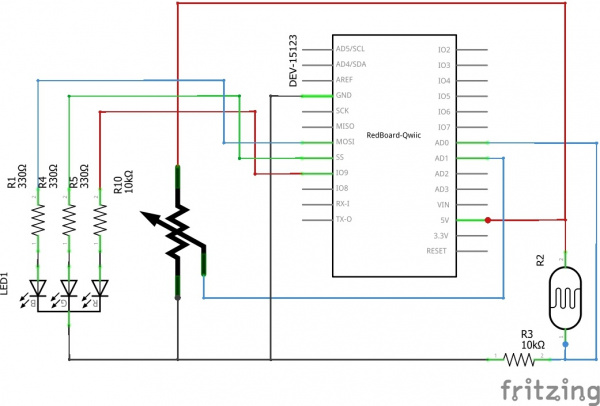
Circuit 1D RGB Nightlight

Having a hard time seeing the circuit? Click on the image for a closer look.

Hookup Table

ComponentRedBoardBreadboardBreadboardBreadboardBreadboard
RGB LED A5 (RED)A4 (GND)A3 (GREEN)A2 (BLUE)
330Ω Resistor
(orange, orange, brown)
E2F2
330Ω Resistor
(orange, orange, brown)
E3F3
330Ω Resistor
(orange, orange, brown)
E5F5
Jumper WireE4GND Rail ( - )
Jumper WireDigital Pin 9J5
Jumper WireDigital Pin 10J3
Jumper WireDigital Pin 11J2
Jumper Wire5V5V Rail ( + )
Jumper WireGNDGND Rail ( - )
PotentiometerB15B16B17
Jumper WireAnalog Pin 1 (A1)E16
Jumper WireE155V Rail ( + )
Jumper WireE17GND Rail ( - )
PhotoresistorA26B25
10kΩ Resistor
(brown, black, orange)
C26D27
Jumper WireAnalog Pin 0 (A0)E26
Jumper WireE255V Rail ( + )
Jumper WireE27GND Rail ( - )

In the table, polarized components are shown with a warning triangle and the whole row highlighted yellow.

Open the Sketch

To open the code, go to: File > Examples > SIK_Guide_Code-V_4 > SIK_Circuit_1D-RGBNightlight

You can also copy and paste the following code into the Arduino IDE. Hit upload, and see what happens!

language:cpp
/*
SparkFun Inventor’s Kit
Circuit 1D-RGB Nightlight

Turns an RGB LED on or off based on the light level read by a photoresistor.
Change colors by turning the potentiometer.

This sketch was written by SparkFun Electronics, with lots of help from the Arduino community.
This code is completely free for any use.

View circuit diagram and instructions at: https://learn.sparkfun.com/tutorials/sparkfun-inventors-kit-experiment-guide---v40
Download drawings and code at: https://github.com/sparkfun/SIK-Guide-Code
 */

int photoresistor;          //variable for storing the photoresistor value
int potentiometer;          //this variable will hold a value based on the position of the knob
int threshold = 700;            //if the photoresistor reading is lower than this value the light will turn on

//LEDs are connected to these pins
int RedPin = 9;
int GreenPin = 10;
int BluePin = 11;

void setup() {
  Serial.begin(9600);           //start a serial connection with the computer

  //set the LED pins to output
  pinMode(RedPin,OUTPUT);
  pinMode(GreenPin,OUTPUT);
  pinMode(BluePin,OUTPUT);
}

void loop() {

  photoresistor = analogRead(A0);         //read the value of the photoresistor
  potentiometer = analogRead(A1);

  Serial.print("Photoresistor value:");
  Serial.print(photoresistor);          //print the photoresistor value to the serial monitor
  Serial.print("  Potentiometer value:");
  Serial.println(potentiometer);          //print the potentiometer value to the serial monitor

  if(photoresistor < threshold){          //if it's dark (the photoresistor value is below the threshold) turn the LED on
    //These nested if statements check for a variety of ranges and 
    //call different functions based on the current potentiometer value.
    //Those functions are found at the bottom of the sketch. 
    if(potentiometer > 0 && potentiometer <= 150)
      red();
    if(potentiometer > 150 && potentiometer <= 300)
      orange();
    if(potentiometer > 300 && potentiometer <= 450)
      yellow(); 
    if(potentiometer > 450 && potentiometer <= 600)
      green();
    if(potentiometer > 600 && potentiometer <= 750)
      cyan();
    if(potentiometer > 750 && potentiometer <= 900)
      blue(); 
    if(potentiometer > 900)
      magenta();  
  } 
  else {                                //if it isn't dark turn the LED off

    turnOff();                            //call the turn off function

  }  

  delay(100);                             //short delay so that the printout is easier to read
}

void red (){

    //set the LED pins to values that make red    
    analogWrite(RedPin, 100);
    analogWrite(GreenPin, 0);
    analogWrite(BluePin, 0);
}
void orange (){

    //set the LED pins to values that make orange
    analogWrite(RedPin, 100);
    analogWrite(GreenPin, 50);
    analogWrite(BluePin, 0);
}
void yellow (){

    //set the LED pins to values that make yellow
    analogWrite(RedPin, 100);
    analogWrite(GreenPin, 100);
    analogWrite(BluePin, 0);
}
void green (){

    //set the LED pins to values that make green    
    analogWrite(RedPin, 0);
    analogWrite(GreenPin, 100);
    analogWrite(BluePin, 0);
}
void cyan (){

    //set the LED pins to values that make cyan    
    analogWrite(RedPin, 0);
    analogWrite(GreenPin, 100);
    analogWrite(BluePin, 100);
}
void blue (){

    //set the LED pins to values that make blue
    analogWrite(RedPin, 0);
    analogWrite(GreenPin, 0);
    analogWrite(BluePin, 100);
}
void magenta (){

    //set the LED pins to values that make magenta   
    analogWrite(RedPin, 100);
    analogWrite(GreenPin, 0);
    analogWrite(BluePin, 100);
}
void turnOff (){

    //set all three LED pins to 0 or OFF
    analogWrite(RedPin, 0);
    analogWrite(GreenPin, 0);
    analogWrite(BluePin, 0);
}

What You Should See

This sketch is not dissimilar from the last. It reads the value from the photoresistor, compares it to a threshold value, and turns the RGB LED on or off accordingly. This time, however, we've added a potentiometer back into the circuit. When you twist the pot, you should see the color of the RGB LED change based on the pot's value.

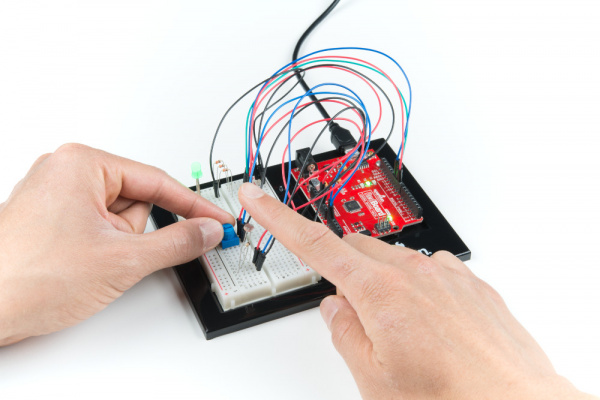
Project 1 Circuit 1D Action

Open the Serial Monitor. The value being read by the light sensor should be printed several times a second. When you turn out the lights or cover the sensor, the LED will shine whatever color your programmed in your color function. Next to the light value, you'll see the potentiometer value print out as well.

Note: If the room you are in is very bright or dark, you may have to change the value of the “threshold” variable in the code to make your night-light turn on and off. See the Troubleshooting section for instructions.

Program Overview

  1. Store the light level from pin A0 in the variable photoresistor.
  2. Store the potentiometer value from pin A1 in the variable potentiometer.
  3. If the light level variable is above the threshold, call the function that turns the RGB LED off.
  4. If the light level variable is below the threshold, call one of the color functions to turn the RGB LED on.
  5. If potentiometer is between 0 and 150, turn the RGB LED on red.
  6. If potentiometer is between 151 and 300, turn the RGB LED on orange.
  7. If potentiometer is between 301 and 450, turn the RGB LED on yellow.
  8. If potentiometer is between 451 and 600, turn the RGB LED on green.
  9. If potentiometer is between 601 and 750, turn the RGB LED on cyan.
  10. If potentiometer is between 751 and 900, turn the RGB LED on blue.
  11. If potentiometer is greater than 900, turn the RGB LED on magenta.

Code to Note

CodeDescription
Analog Output (PWM):
analogWrite(RedPin, 100);
The analogWrite() function outputs a voltage between 0 and 5V on a pin. The function breaks the range between 0 and 5V into 255 little steps. Note that we are not turning the LED on to full brightness (255) in this code so that the night-light is not too bright. Feel free to change these values and see what happens.
Nested if Statements:
if(logic statement) {
code to be run if the logic statement is true}
if(logic statement) {
code to be run if the logic statement is true}
}
A nested if statement is one or more if statements "nested" inside of another if statement. If the parent if statement is true, then the code looks at each of the nested if statements and executes any that are true. If the parent if statement is false, then none of the nested statements will execute.
More Logical Operators:
if(potentiometer > 0 && potentiometer <= 150)
These if statements are checking for two conditions by using the AND (&&) operator. In this line, the if statement will only be true if the value of the variable potentiometer is greater than 0 AND if the value is less than or equal to 150. By using &&, the program allows the LED to have many color states.
Defining a Function:
void function_name () {
code to run inside function }
This simple version of a function executes the code inside the curly brackets whenever the name is written in the main program.
Calling a Function:
function_name();
Calls a function that you have created. In a later circuit, you will learn how to make more complicated functions that take data from the main program (these pieces of data are called parameters).

Coding Challenges

ChallengeDescription
Add more colorsYou can create many more colors with the RGB LED. Use the analogWrite() function to blend different values of red, green and blue together to make even more colors. You can divide the potentiometer value up more and make more nested if statements so that you can have more colors as you twist the knob.
Multi color blinkTry using delays and multiple color functions to have your RGB LED change between multiple colors.
Change the thresholdTry setting your threshold variable by reading the value of a potentiometer with analogRead(). By turning the potentiometer, you can then change the threshold level and adjust your night-light for different rooms.
Fading the LEDTry using a loop with the analogWrite() to get your LED to pulse gently or smoothly transition between colors.

Troubleshooting

ProblemSolution
The LED never turns on or offOpen the Serial Monitor in Arduino and make sure that your photoresistor is returning values between 0 and 1023. Try covering the photoresistor; the values should change. If they do not change, check the wiring of the photoresistor.
If your photoresistor is working correctly, make sure that your threshold variable sits in between the value that the photoresistor reads when it is bright and the value that the photoresistor reads when it is dark (e.g., bright = 850, dark = 600, threshold = 700).
My LED doesn’t show the colors that I expectMake sure that all three of the pins driving your RGB LED are set to OUTPUT, using the pinMode() command in the setup section of the code. Then make sure that each LED is wired properly.
Nothing is printing in the Serial MonitorTry unplugging your USB cable and plugging it back in. In the Arduino IDE, go to Tools > Port, and make sure that you select the right port.

Project 2: Sound

In Project 2, you will venture into the world of buttons and buzzers while building your own Simon Says game! Simon Says is a game in which the LEDs flash a pattern of red, green, yellow and blue blinks, and the user must recreate the pattern using color-coded buttons before the timer runs out.

Project 2

New Components Introduced in This Project

Each of the components listed below will be described in more detail as you progress through each circuit.

  • Buzzer
  • Buttons

New Concepts Introduced in This Project

Each of the concepts listed below will be described in more detail as you progress through each circuit.

  • Arrays
  • Binary
  • Digital Inputs
  • Pull-up Resistors
  • For Loops
  • Measuring Elapsed Time

You Will Learn

  • How to make tones with a buzzer
  • How to read a button using digital inputs
  • How to program a game

Circuit 2A: Buzzer

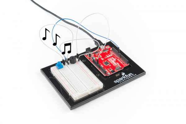
In this circuit, you'll use the RedBoard and a small buzzer to make music, and you'll learn how to program your own songs using arrays.

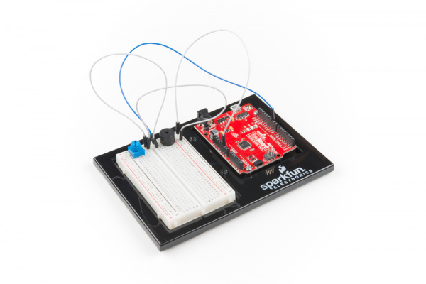
Project2 Circuit 2A

Parts Needed

Grab the following quantities of each part listed to build this circuit:

parts

New Components

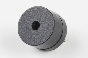
Buzzer

The buzzer uses a small magnetic coil to vibrate a metal disc inside a plastic housing. By pulsing electricity through the coil at different rates, different frequencies (pitches) of sound can be produced. Attaching a potentiometer to the output allows you to limit the amount of current moving through the buzzer and lower its volume.

buzzer

New Concepts

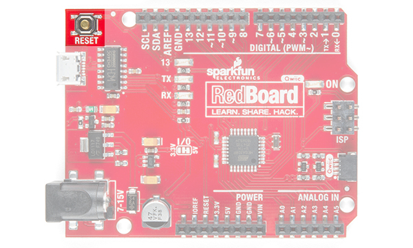
Reset Button

The RedBoard has a built-in reset button. This button will reset the board and start the code over from the beginning, running what is in setup() and then loop().

reset button

Tone Function

To control the buzzer, you will use the tone function. This function is similar to PWM in that it generates a wave that is of a certain frequency on the specified pin. The frequency and duration can both be passed to the tone() function when calling it. To turn the tone off, you need to call noTone() or pass a duration of time for it to play and then stop. Unlike PWM, tone() can be used on any digital pin.

Arrays

Arrays are used like variables, but they can store multiple values. The simplest array is just a list. Imagine that you want to store the frequency for each note of the C major scale. We could make seven variables and assign a frequency to each one, or we could use an array and store all seven in the same array, as shown below. To refer to a specific value in the array, an index number is used. Arrays are indexed from 0. For example, to call the first element in the array, use array_name[0];; to call the second element, use array_name[1]; and so on.

Musical NoteFrequency (Hz)Using VariablesUsing an Array
A220aFrequencyfrequency[0]
B247bFrequencyfrequency[1]
C261cFrequencyfrequency[2]
D294dFrequencyfrequency[3]
E330eFrequencyfrequency[4]
F349fFrequencyfrequency[5]
G392gFrequencyfrequency[6]

Hardware Hookup

Polarized Components Pay special attention to the component’s markings indicating how to place it on the breadboard. Polarized components can only be connected to a circuit in one direction.

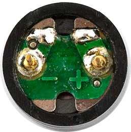
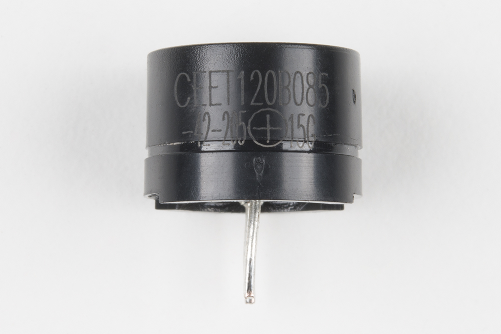
The buzzer is polarized. To see which leg is positive and which is negative, flip the buzzer over and look at the markings underneath. Keep track of which pin is where, as they will be hard to see once inserted into the breadboard. There is also text on the positive side of the buzzer, along with a tiny (+) symbol.
Volume Knob

All of the circuits in Project 2 make use of a potentiometer as a rudimentary volume knob. Notice that only two of the potentiometer's legs are used in these circuits. In these instances, the potentiometer is acting as a variable resistor, limiting the amount of current flowing to the speaker and thus affecting the volume as you turn the knob. This is similar to the current-limiting resistor used to limit current to the LED in circuit 1A --- only this time the resistance is variable.

Ready to start hooking everything up? Check out the circuit diagram and hookup table below to see how everything is connected.

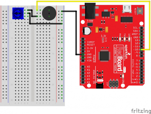
Circuit Diagram

Circuit 2A Fritzing

Having a hard time seeing the circuit? Click on the image for a closer look.

Hookup Table

ComponentRedBoardBreadboardBreadboardBreadboard
BuzzerJ1 (Buzzer + )J3 (Buzzer - )
PotentiometerB1B2B3
Jumper WireGNDGND Rail ( - )
Jumper WireDigital Pin 10F1
Jumper WireE2GND Rail ( - )
Jumper WireE1F3

In the table, polarized components are shown with a warning triangle and the whole row highlighted yellow.

Open the Sketch

To open the code, go to: File > Examples > SIK_Guide_Code-V_4 > SIK_Circuit_2A-Buzzer

You can also copy and paste the following code into the Arduino IDE. Hit upload, and see what happens!

language:cpp
/*
SparkFun Inventor’s Kit
Circuit 2A - Buzzer

Play notes using a buzzer connected to pin 10

This sketch was written by SparkFun Electronics, with lots of help from the Arduino community.
This code is completely free for any use.

View circuit diagram and instructions at: https://learn.sparkfun.com/tutorials/sparkfun-inventors-kit-experiment-guide---v40
Download drawings and code at: https://github.com/sparkfun/SIK-Guide-Code
*/


int speakerPin = 10;               //the pin that buzzer is connected to

void setup()
{
  pinMode(speakerPin, OUTPUT);    //set the output pin for the speaker
}

void loop()
{

  play('g', 2);       //ha
  play('g', 1);       //ppy
  play('a', 4);       //birth
  play('g', 4);       //day
  play('C', 4);       //to
  play('b', 4);       //you

  play(' ', 2);       //pause for 2 beats

  play('g', 2);       //ha     
  play('g', 1);       //ppy
  play('a', 4);       //birth
  play('g', 4);       //day
  play('D', 4);       //to
  play('C', 4);       //you

  play(' ', 2);       //pause for 2 beats

  play('g', 2);       //ha
  play('g', 1);       //ppy
  play('G', 4);       //birth
  play('E', 4);       //day
  play('C', 4);       //dear
  play('b', 4);       //your
  play('a', 6);       //name

  play(' ', 2);       //pause for 2 beats

  play('F', 2);       //ha
  play('F', 1);       //ppy
  play('E', 4);       //birth
  play('C', 4);       //day
  play('D', 4);       //to
  play('C', 6);       //you

  while(true){}       //get stuck in this loop forever so that the song only plays once
}


void play( char note, int beats)
{
  int numNotes = 14;  // number of notes in our note and frequency array (there are 15 values, but arrays start at 0)

  //Note: these notes are C major (there are no sharps or flats)

  //this array is used to look up the notes
  char notes[] = { 'c', 'd', 'e', 'f', 'g', 'a', 'b', 'C', 'D', 'E', 'F', 'G', 'A', 'B', ' '};
  //this array matches frequencies with each letter (e.g. the 4th note is 'f', the 4th frequency is 175)
  int frequencies[] = {131, 147, 165, 175, 196, 220, 247, 262, 294, 330, 349, 392, 440, 494, 0};

  int currentFrequency = 0;    //the frequency that we find when we look up a frequency in the arrays
  int beatLength = 150;   //the length of one beat (changing this will speed up or slow down the tempo of the song)

  //look up the frequency that corresponds to the note
  for (int i = 0; i < numNotes; i++)  // check each value in notes from 0 to 14
  {
    if (notes[i] == note)             // does the letter passed to the play function match the letter in the array?
    {
      currentFrequency = frequencies[i];   // Yes! Set the current frequency to match that note
    }
  }

  //play the frequency that matched our letter for the number of beats passed to the play function
  tone(speakerPin, currentFrequency, beats * beatLength);   
  delay(beats* beatLength);   //wait for the length of the tone so that it has time to play
  delay(50);                  //a little delay between the notes makes the song sound more natural

}

/* CHART OF FREQUENCIES FOR NOTES IN C MAJOR
Note      Frequency (Hz)
c        131
d        147
e        165
f        175
g        196
a        220
b        247
C        262
D        294
E        330
F        349
G        392
A        440
B        494
*/

What You Should See

When the program begins, a song will play from the buzzer once. To replay the song, press the reset button on the RedBoard. Use the potentiometer to adjust the volume.

Project 2 Circuit 2A Action

Program Overview

Inside the main loop:

  1. Play the first note for x number of beats using the play function. a. (Inside the play function:) Take the note passed to the play function and compare it to each letter in the notes array. When you find a note that matches, remember the index position of that note (e.g., 6th entry in the notes array). b. Get a frequency from the frequency array that has the same index as the note that matched (e.g., the 6th frequency). c. Play that frequency for the number of beats passed to the play function.
  2. Play the second note using the play function
    ...and so on.

Code to Note

CodeDescription
Character Variables:
void play( char note, int beats)
The char, or character, variable to store character values. For example, in this sketch, the play() function gets passed two variables, a character variable that represents the mucial note we want to play and an integer variable that represents how long to play that note. A second array takes the character variable and associates a frequency value to it. This makes programming a song easier as you can just reference the character and not the exact frequency.
Tone Function:
tone(pin, frequency, duration);
The tone() function will pulse power to a pin at a specific frequency. The duration controls how long the sound will play. Tone can be used on any digital pin.
Declaring an Array:
arrray_name[array_size]; or arrray_name[] = {array elements};
To declare an array, you must give it a name, then either tell Arduino how many positions the array will have or assign a list of values to the array.
Calling an Array:
array_name[index #];
To call one of the values in an array, simply type the name of the array and the index of the value. You can use a variable instead of a number in between the square brackets. Don't forget the index starts at 0, not 1, so to call the first element, use array_name[0];.

Coding Challenges

ChallengeDescription
Change the tempo of the songExperiment with the beatLength; variable to change the tempo of the song.
Make your own songTry changing the notes to make a different song. Spaces "" can be used for rests in the song.

Troubleshooting

ProblemSolution
The song is too quiet or too loudTurn the potentiometer to adjust the volume.
No sound is playingTry pressing the reset button on the RedBoard. If that doesn’t work, check your wiring of the buzzer. It's easy to misalign a pin with a jumper wire.

Circuit 2B: Digital Trumpet

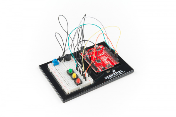
Learn about digital inputs and buttons as you build your own digital trumpet!

Project2 Circuit 2B

Parts Needed

Grab the following quantities of each part listed to build this circuit:

parts

New Components

Buttons

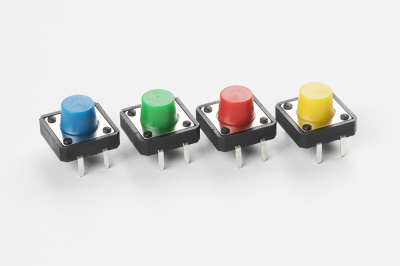
Buttons, also known as momentary switches, are switches that only remain in their on state as long as they’re being actuated, or pressed. Most often momentary switches are best used for intermittent user-input cases: reset button and keypad buttons. These switches have a nice, tactile, “clicky” feedback when you press them.

multicolored buttons

Note that the different colors are just aesthetic. All of the buttons included behave the same no matter their color.

New Concepts

Binary Number System

Number systems are the methods we use to represent numbers. We’ve all been mostly operating within the comfy confines of a base-10 number system, but there are many others. The base-2 system, otherwise known as binary, is common when dealing with computers and electronics. There are really only two ways to represent the state of anything: ON or OFF, HIGH or LOW, 1 or 0. And so, almost all electronics rely on a base-2 number system to store and manipulate numbers. The heavy reliance electronics places on binary numbers means it’s important to know how the base-2 number system works.

Digital Input

In circuit 1A, you worked with digital outputs. This circuit focuses on digital inputs. Digital inputs only care if something is in one of two states: TRUE or FALSE, HIGH or LOW, ON or OFF. Digital inputs are great for determining if a button has been pressed or if a switch has been flipped.

Pull-up Resistors

A pull-up resistor is a small circuit that holds the voltage HIGH (5V) on a pin until a button is pressed, pulling the voltage LOW (0V). The most common place you will see a pull-up resistor is when working with buttons. A pull-up resistor keeps the button in one state until it is pressed. The RedBoard has built-in pull-up resistors, but they can also be added to a circuit externally. This circuit uses the internal pull-up resistors, covered in more detail in the Code to Note section.

Hardware Hookup

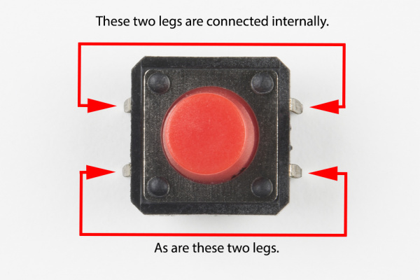
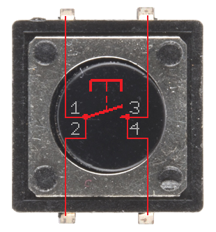
Buttons are not polarized. However, they do merit a closer look. Buttons make momentary contact from one connection to another, so why are there four legs on each button? The answer is to provide more stability and support to the buttons in your breadboard circuit. Each row of legs is connected internally. When the button is pressed, one row connects to the other, making a connection between all four pins.

button pins explained

If the button's legs don't line up with the slots on the breadboard, rotate it 90 degrees.

Ready to start hooking everything up? Check out the circuit diagram and hookup table below to see how everything is connected.

Circuit Diagram

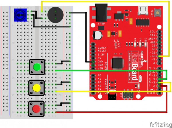
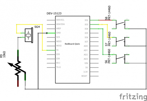
Circuit 2B Fritzing

Having a hard time seeing the circuit? Click on the image for a closer look.

Hookup Table

ComponentRedBoardBreadboardBreadboardBreadboard
BuzzerJ1 (Buzzer + )J3 (Buzzer - )
PotentiometerB1B2B3
Jumper WireGNDGND Rail ( - )
Jumper WireDigital Pin 10F1
Jumper WireE2GND Rail ( - )
Jumper WireE1F3
Push ButtonD16/D18G16/G18
Push ButtonD22/D24G22/G24
Push ButtonD28/D30G28/G30
Jumper WireDigital Pin 4J18
Jumper WireDigital Pin 3J24
Jumper WireDigital Pin 2J30
Jumper WireJ16GND Rail ( - )
Jumper WireJ22GND Rail ( - )
Jumper WireJ28GND Rail ( - )

In the table, polarized components are shown with a warning triangle and the whole row highlighted yellow.

Open the Sketch

To open the code, go to: File > Examples > SIK_Guide_Code-V_4 > SIK_Circuit_2B-ButtonTrumpet

You can also copy and paste the following code into the Arduino IDE. Hit upload, and see what happens!

language:cpp
/*
SparkFun Inventor’s Kit
Circuit 2B-DigitalTrumpet

Use 3 buttons plugged to play musical notes on a buzzer.

This sketch was written by SparkFun Electronics, with lots of help from the Arduino community.
This code is completely free for any use.

View circuit diagram and instructions at: https://learn.sparkfun.com/tutorials/sparkfun-inventors-kit-experiment-guide---v40
Download drawings and code at: https://github.com/sparkfun/SIK-Guide-Code
*/

//set the pins for the button and buzzer
int firstKeyPin = 2;
int secondKeyPin = 3;
int thirdKeyPin = 4;

int buzzerPin = 10;


void setup() {
  //set the button pins as inputs
  pinMode(firstKeyPin, INPUT_PULLUP);
  pinMode(secondKeyPin, INPUT_PULLUP);
  pinMode(thirdKeyPin, INPUT_PULLUP);

  //set the buzzer pin as an output
  pinMode(buzzerPin, OUTPUT);
}

void loop() {

  if(digitalRead(firstKeyPin) == LOW){        //if the first key is pressed
    tone(buzzerPin, 262);                     //play the frequency for c
  }
  else if(digitalRead(secondKeyPin) == LOW){  //if the second key is pressed
    tone(buzzerPin, 330);                     //play the frequency for e
  }
  else if(digitalRead(thirdKeyPin) == LOW){   //if the third key is pressed
    tone(buzzerPin, 392);                     //play the frequency for g
  }
  else{
    noTone(buzzerPin);                        //if no key is pressed turn the buzzer off
  }
}

  /*
  note  frequency
  c     262 Hz
  d     294 Hz
  e     330 Hz
  f     349 Hz
  g     392 Hz
  a     440 Hz
  b     494 Hz
  C     523 Hz
  */

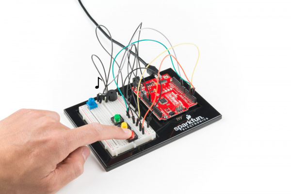
What You Should See

Different tones will play when you press different keys. Turning the potentiometer will adjust the volume.

Project 2 Circuit 2B Action

Program Overview

  1. Check to see if the first button is pressed. a. If it is, play the frequency for c. b. If it isn’t, skip to the next else if statement.
  2. Check to see if the second button is pressed. a. If it is, play the frequency for e. b. If it isn’t, skip to the next else if statement.
  3. Check to see if the second button is pressed. a. If it is, play the frequency for g. b. If it isn’t, skip to the next else if statement.
  4. If none of the if statements are true a. Turn the buzzer off.

Code to Note

CodeDescription
Internal Pull-Up Resistor:
pinMode(firstKeyPin, INPUT_PULLUP);
To declare a standard input, use the line pinMode(pin_name, INPUT). If you would like to use one of the RedBoard's built-in pull-up 20k&ohm; resistors, it would look like this: pinMode(firstKeyPin, INPUT_PULLUP);. The advantage of external pull-ups is being able to choose a more exact value for the resistor.
Digital Input:
digitalRead(pin);
Check to see if an input pin is reading HIGH (5V) or LOW (0V). Returns TRUE (1) or FALSE (0) depending on the reading.
Is Equal to:
if(digitalRead(firstKeyPin) == LOW)
This is another logical operator. The 'is equal to' symbol (==) can be confusing. Two equals signs are equivalent to asking, "Are these two values equal to one another?" On the other hand, one equals sign in code is assigning a particular variable to a value. Don't forget to add the second equals sign if you are comparing two values.

Coding Challenges

ChallengeDescription
Change the key of each buttonUse the frequency table in the comment section at the end of the code to change the notes that each button plays.
Play more than three notes with if statementsBy using combinations of buttons, you can play up to seven notes of the scale. You can do this in a few ways. To get more practice with if statements, try adding seven if statements and using the Boolean AND (&&) operator to represent all of the combinations of keys.
Play more than three notes with binary mathYou can use a clever math equation to play more than three notes with your three keys. By multiplying each key by a different number, then adding up all of these numbers, you can make a math equation that produces a different number for each combination of keys.

Troubleshooting

ProblemSolution
The buzzer is too loud or too quietTurn the potentiometer to adjust the volume.
The RedBoard thinks one key is always pressedCheck your wiring. You may have ground and 5V backward if one or more buttons behave as though they're pressed all the time.
The buttons are not workingFirst, make sure that the wiring is correct. It is easy to misalign a wire with a button leg. Second, make sure that you have declared your buttons as inputs and have enabled the internal pull-up resistors with INPUT_PULLUP.

Circuit 2C: Simon Says Game

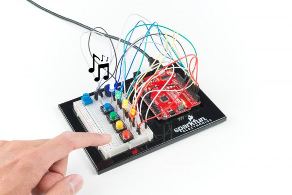
The Simon Says game uses LEDs to flash a pattern, which the player must remember and repeat using four buttons. The classic Simon game has been a hit since the 1980s. Now you can build your own!

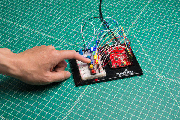
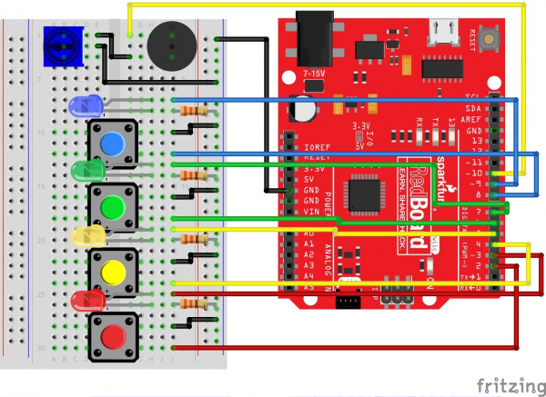
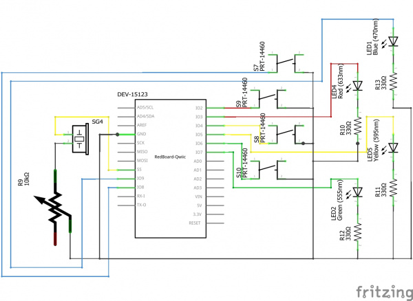
Project 2 Circuit 2C

Parts Needed

Grab the following quantities of each part listed to build this circuit:

parts

New Concepts

For Loops

For loops repeat a section of code a set number of times. The loop works by using a counter (usually programmers use the letter “i” for this variable) that increases each loop until it reaches a stop value. Here’s an example of a simple for loop:

language:c
for (int i = 0; i < 5; i++){
    Serial.print(i);
}

The for loop takes three parameters in the brackets, separated by semicolons. The first parameter is the start value. In this case, integer i starts at 0. The second value is the stop condition. In this case, we stop the loop when i is no longer less than 5 (i < 5 is no longer true). The final parameter is an increment value. i++ is shorthand for increase i by 1 each time, but you could also increase i by different amounts. This loop would repeat five times. Each time it would run the code in between the brackets, which prints the value of i to the serial monitor.

Measuring Durations of Time With millis()

The RedBoard has a built-in clock that keeps accurate time. You can use the millis() command to see how many milliseconds have passed since the RedBoard was last powered. By storing the time when an event happens and then subtracting the current time, you can measure the number of milliseconds (and thus seconds) that have passed. This sketch uses this function to set a time limit for repeating the pattern.

Custom Functions

This sketch uses several user-defined functions. These functions perform operations that are needed many times in the program (for example, reading which button is currently pressed or turning all of the LEDs off). Functions are essential to make more complex programs readable and compact.

Hardware Hookup

Ready to start hooking everything up? Check out the circuit diagram and hookup table below to see how everything is connected.

Circuit Diagram

Circuit 2C Fritzing

Having a hard time seeing the circuit? Click on the image for a closer look.

Hookup Table

ComponentRedBoardBreadboardBreadboardBreadboard
BuzzerJ1 (Buzzer + )J3 (Buzzer - )
PotentiometerB1B2B3
Jumper WireGNDGND Rail ( - )
Jumper WireDigital Pin 10F1
Jumper WireE2GND Rail ( - )
Jumper WireE1F3
Push ButtonD10/D12G10/G12
Push ButtonD16/D18G16/G18
Push ButtonD22/D24G22/G24
Push ButtonD28/D30G28/G30
Jumper WireDigital Pin 8J12
Jumper WireDigital Pin 6J18
Jumper WireDigital Pin 4J24
Jumper WireDigital Pin 2J30
Jumper WireJ10GND Rail ( - )
Jumper WireJ16GND Rail ( - )
Jumper WireJ22GND Rail ( - )
Jumper WireJ28GND Rail ( - )
Blue LED H7 LED ( + )H8 LED ( - )
Green LED H13 LED ( + )H14 LED ( - )
Yellow LED H19 LED ( + )H20 LED ( - )
Red LED H25 LED ( + )H26 LED ( - )
Jumper WireDigital Pin 9J7
Jumper WireDigital Pin 7J13
Jumper WireDigital Pin 5J19
Jumper WireDigital Pin 3J25
330Ω Resistor
(orange, orange, brown)
J8GND Rail ( - )
330Ω Resistor
(orange, orange, brown)
J14GND Rail ( - )
330Ω Resistor
(orange, orange, brown)
j20GND Rail ( - )
330Ω Resistor
(orange, orange, brown)
J26GND Rail ( - )

In the table, polarized components are shown with a warning triangle and the whole row highlighted yellow.

Open the Sketch

To open the code, go to: File > Examples > SIK_Guide_Code-V_4 > SIK_Circuit_2C-SimonSays

You can also copy and paste the following code into the Arduino IDE. Hit upload, and see what happens!

language:cpp
/*
  SparkFun Inventor’s Kit
  Circuit 2C-Simon Says

  The Simon Says game flashes a pattern using LED lights, then the player must repeat the pattern.

  This sketch was written by SparkFun Electronics, with lots of help from the Arduino community.
  This code is completely free for any use.

  View circuit diagram and instructions at: https://learn.sparkfun.com/tutorials/sparkfun-inventors-kit-experiment-guide---v40
  Download drawings and code at: https://github.com/sparkfun/SIK-Guide-Code
*/

//set the pins where the buttons, LEDs and buzzer connect
int button[] = {2, 4, 6, 8};  //red is button[0], yellow is button[1], green is button[2], blue is button[3]
int led[] = {3, 5, 7, 9};     //red is led[0], yellow is led[1], green is led[2], blue is led[3]
int tones[] = {262, 330, 392, 494};   //tones to play with each button (c, e, g, b)

int roundsToWin = 10;         //number of rounds the player has to play before they win the game (the array can only hold up to 16 rounds)
int buttonSequence[16];       //make an array of numbers that will be the sequence that the player needs to remember

int buzzerPin = 10;           //pin that the buzzer is connected to

int pressedButton = 4;        //a variable to remember which button is being pressed. 4 is the value if no button is being pressed.
int roundCounter = 1;         //keeps track of what round the player is on


long startTime = 0;           //timer variable for time limit on button press
long timeLimit = 2000;        //time limit to hit a button

boolean gameStarted = false;      //variable to tell the game whether or not to play the start sequence

void setup() {

  //set all of the button pins to input_pullup (use the built-in pull-up resistors)
  pinMode(button[0], INPUT_PULLUP);
  pinMode(button[1], INPUT_PULLUP);
  pinMode(button[2], INPUT_PULLUP);
  pinMode(button[3], INPUT_PULLUP);

  //set all of the LED pins to output
  pinMode(led[0], OUTPUT);
  pinMode(led[1], OUTPUT);
  pinMode(led[2], OUTPUT);
  pinMode(led[3], OUTPUT);

  pinMode(buzzerPin, OUTPUT);   //set the buzzer pin to output
}

void loop() {

  if (gameStarted == false) {   //if the game hasn't started yet
    startSequence();            //flash the start sequence
    roundCounter = 0;           //reset the round counter
    delay(1500);                //wait a second and a half
    gameStarted = true;         //set gameStarted to true so that this sequence doesn't start again
  }

  //each round, start by flashing out the sequence to be repeated
  for (int i = 0; i <= roundCounter; i++) { //go through the array up to the current round number
    flashLED(buttonSequence[i]);          //turn on the LED for that array position and play the sound
    delay(200);                           //wait
    allLEDoff();                          //turn all of the LEDs off
    delay(200);
  }

  //then start going through the sequence one at a time and see if the user presses the correct button
  for (int i = 0; i <= roundCounter; i++) { //for each button to be pressed in the sequence

    startTime = millis();                 //record the start time

    while (gameStarted == true) { //loop until the player presses a button or the time limit is up (the time limit check is in an if statement)

      pressedButton = buttonCheck();      //every loop check to see which button is pressed

      if (pressedButton < 4) {            //if a button is pressed... (4 means that no button is pressed)

        flashLED(pressedButton);          //flash the LED for the button that was pressed

        if (pressedButton == buttonSequence[i]) { //if the button matches the button in the sequence
          delay(250);                   //leave the LED light on for a moment
          allLEDoff();                  //then turn off all of the lights and
          break;                        //end the while loop (this will go to the next number in the for loop)

        } else {                          //if the button doesn't match the button in the sequence
          loseSequence();               //play the lose sequence (the loose sequence stops the program)
          break;                        //when the program gets back from the lose sequence, break the while loop so that the game can start over
        }

      } else {                            //if no button is pressed
        allLEDoff();                      //turn all the LEDs off
      }

      //check to see if the time limit is up
      if (millis() - startTime > timeLimit) { //if the time limit is up
        loseSequence();                       //play the lose sequence
        break;                                //when the program gets back from the lose sequence, break the while loop so that the game can start over
      }
    }
  }

  if (gameStarted == true) {
    roundCounter = roundCounter + 1;      //increase the round number by 1

    if (roundCounter >= roundsToWin) {              //if the player has gotten to the 16th round
      winSequence();                      //play the winning song
    }

    delay(500);                           //wait for half a second between rounds
  }

}

//----------FUNCTIONS------------

//FLASH LED
void flashLED (int ledNumber) {
  digitalWrite(led[ledNumber], HIGH);
  tone(buzzerPin, tones[ledNumber]);
}

//TURN ALL LEDS OFF
void allLEDoff () {
  //turn all the LEDs off
  digitalWrite(led[0], LOW);
  digitalWrite(led[1], LOW);
  digitalWrite(led[2], LOW);
  digitalWrite(led[3], LOW);
  //turn the buzzer off
  noTone(buzzerPin);
}

//CHECK WHICH BUTTON IS PRESSED
int buttonCheck() {
  //check if any buttons are being pressed
  if (digitalRead(button[0]) == LOW) {
    return 0;
  } else if (digitalRead(button[1]) == LOW) {
    return 1;
  } else if (digitalRead(button[2]) == LOW) {
    return 2;
  } else if (digitalRead(button[3]) == LOW) {
    return 3;
  } else {
    return 4; //this will be the value for no button being pressed
  }
}

//START SEQUENCE
void startSequence() {

  randomSeed(analogRead(A0));   //make sure the random numbers are really random

  //populate the buttonSequence array with random numbers from 0 to 3
  for (int i = 0; i <= roundsToWin; i++) {
    buttonSequence[i] = round(random(0, 4));
  }

  //flash all of the LEDs when the game starts
  for (int i = 0; i <= 3; i++) {

    tone(buzzerPin, tones[i], 200); //play one of the 4 tones

    //turn all of the leds on
    digitalWrite(led[0], HIGH);
    digitalWrite(led[1], HIGH);
    digitalWrite(led[2], HIGH);
    digitalWrite(led[3], HIGH);

    delay(100);         //wait for a moment

    //turn all of the leds off
    digitalWrite(led[0], LOW);
    digitalWrite(led[1], LOW);
    digitalWrite(led[2], LOW);
    digitalWrite(led[3], LOW);

    delay(100);   //wait for a moment

  } //this will repeat 4 times
}

//WIN SEQUENCE
void winSequence() {

  //turn all the LEDs on
  for (int j = 0; j <= 3; j++) {
    digitalWrite(led[j], HIGH);
  }

  //play the 1Up noise
  tone(buzzerPin, 1318, 150);   //E6
  delay(175);
  tone(buzzerPin, 1567, 150);   //G6
  delay(175);
  tone(buzzerPin, 2637, 150);   //E7
  delay(175);
  tone(buzzerPin, 2093, 150);   //C7
  delay(175);
  tone(buzzerPin, 2349, 150);   //D7
  delay(175);
  tone(buzzerPin, 3135, 500);   //G7
  delay(500);

  //wait until a button is pressed
  do {
    pressedButton = buttonCheck();
  } while (pressedButton > 3);
  delay(100);

  gameStarted = false;   //reset the game so that the start sequence will play again.

}

//LOSE SEQUENCE
void loseSequence() {

  //turn all the LEDs on
  for (int j = 0; j <= 3; j++) {
    digitalWrite(led[j], HIGH);
  }

  //play the 1Up noise
  tone(buzzerPin, 130, 250);   //E6
  delay(275);
  tone(buzzerPin, 73, 250);   //G6
  delay(275);
  tone(buzzerPin, 65, 150);   //E7
  delay(175);
  tone(buzzerPin, 98, 500);   //C7
  delay(500);

  //wait until a button is pressed
  do {
    pressedButton = buttonCheck();
  } while (pressedButton > 3);
  delay(200);

  gameStarted = false;   //reset the game so that the start sequence will play again.
}

What You Should See

The circuit will flash all of the LEDs and play a melody. After a few seconds, it will flash the first light in the pattern. If you repeat the pattern correctly by pressing the corresponding colored button, then the game will move to the next round and add another color to the pattern sequence. If you make a mistake, the loss melody will play. If you get to round 10, the win melody will play. Press any button to start a new game.

Project 2 Circuit 2C Action

Program Overview

  1. Check if a new game is starting. If it is, play the start sequence. Reset the counter that keeps track of rounds, and randomly generate a sequence of numbers from 0 to 3 that control which LEDs the user will have to remember.
  2. The game works in rounds that progress from 0 to 10. Each round the game will flash LEDs in a pattern, then the player has to recreate the pattern by pressing the button(s) that match the LED(s). In the first round, one LED will flash, and the player will have to press one button. In the eighth round, eight LEDs will flash, and the player will have to press eight buttons.
  3. Use a loop to flash LEDs from the sequence until you have flashed the number of LEDs that matches the round number (1 for round 1, 2 for round 2, etc).
  4. Start a timer, and wait for the player to press a button. The player has 1.5 seconds to press the correct button. a. If the time limit runs out before a button is pressed, the player loses. b. If the player presses the wrong button, the player loses. c. If the player presses the right button, move on to the next number in the sequence. d. Repeat this process until the player has lost or correctly repeated the sequence for this round.
  5. If the player repeats the entire sequence for that round. Increase the round number by one (this will add one extra item to the end of the pattern). Then go back to step 3.
  6. Keep incrementing the round until the player loses or the player finishes 10 rounds. If the player finishes 10 rounds, play the winning sequence.

Code to Note

CodeDescription
Elapsed Time:
millis();
The millis function returns the number of milliseconds that have passed since the RedBoard was last turned on.
Boolean Variables:
boolean variable_name;
The name for these variables comes from Boolean logic. The Boolean variable type only has two values: 1 or 0, HIGH or LOW, TRUE or FALSE. Using Boolean variables helps save memory on your microcontroller if you only need to know if something is true or false. Space in your microcontroller's memory is reserved when a variable is declared. How much memory is reserved depends on the type of variable.
Storing pin numbers in Arrays:
int led[] = {3,5,7,9};
Sometimes you will want to cycle through all of the LEDs or buttons connected to a project. You can do this by storing a sequence of pin numbers in an array. The advantage of having pins in an array instead of a sequence of variables is that you can use a loop to easily cycle through each pin.
User Functions Description
flashLED(# for LED to flash);This turns one of the four LEDs on and plays the tone associated with it.
0 = Red, 1 = Yellow, 2 = Green, 3 = Blue.
allLEDoff();Turns all four LEDs off.
buttonCheck();Uses digitalRead() to check which button is pressed. Returns 0, 1, 2 or 3 if one of the buttons is pressed. Returns 4 if no button is pressed.
startSequence();Flashes the LEDs and plays tones in a sequence. Resets the round counter and generates a new random sequence for the user to remember.
winSequence();Plays a sequence of tones, turns all of the LEDs on, then waits for the player to press a button. If a button is pressed, restarts the game.
loseSequence();Plays a sequence of tones, turns all of the LEDs on, then waits for the player to press a button. If a button is pressed, restarts the game.

Coding Challenges

ChallengeDescription
Change the difficulty of the gameChange the difficulty of the game by changing how fast the player has to press each button or by increasing or decreasing the number of rounds needed to win. Note that if you increase the number of rounds to be larger than 16, you will need to change the size of the “buttonSequence” array (it is set at the top of the code in a line that looks like this: int buttonSequence[16];.
Change the sound effectsTry changing the sequence of notes that play when you start, win or lose the game.
2-Player modeReady for a real coding challenge? Try changing the code so that two players can play head-to-head.

Troubleshooting

ProblemSolution
One of the LEDs isn’t lighting upMake sure your LED is flipped around in the right direction. If the LED still doesn’t work, try wiggling the resistor and the wires that connect to the LED.
The buzzer is too loud or too quietTurn the potentiometer to adjust the volume
One of the buttons isn’t workingCarefully check your wiring for each button. One leg of the button should connect to a pin on the RedBoard; the other leg should connect to the ground rail on the breadboard.
None of the buttons or LEDs is workingMake sure you don't have 5V and GND mixed up. Double check that you have a GND connection from the RedBoard to the GND rail on the breadboard.
Still not working?Jumper wires unfortunately can go "bad" from getting bent too much. The copper wire inside can break, leaving an open connection in your circuit. If you are certain that your circuit is wired correctly and that your code is error-free and uploaded, but you are still encountering issues, try replacing one or more of the jumper wires for the component that is not working.

Project 3: Motion

Tired of your cat walking all over the kitchen counter? How about the dog getting into the garbage? Need a way to stop your little brother from sneaking into your bedroom? Learn how to protect against all of these annoyances as you build a multipurpose alarm. The alarm detects distance and motion using an ultrasonic distance sensor, and creates motion using a servo motor.

Project 3

New Components Introduced in This Project

Each of the components listed below will be described in more detail as you progress through each circuit.

  • Servo Motor
  • Ultrasonic Distance Sensor

New Concepts Introduced in This Project

Each of the concepts listed below will be described in more detail as you progress through each circuit.

  • PWM Duty Cycle
  • Arduino Libraries
  • Objects and Methods
  • Datasheets
  • Digital Sensors
  • Servo Mechanisms

You Will Learn

  • How to control a servo motor
  • How to use an ultrasonic distance sensor
  • How to move objects using servo mechanisms

Circuit 3A: Servo Motors

In this circuit, you will learn how to wire a servo and control it with code. Servo motors can be told to move to a specific position and stay there. Low-cost servo motors were originally used to steer remote-controlled airplanes and cars, but they have become popular for any project where precise movement is needed.

Project 3 Circuit 3A

Parts Needed

Grab the following quantities of each part listed to build this circuit:

parts

Additional Materials

  • Scissors (NOT INCLUDED)

New Components

Servo Motors

Regular DC motors have two wires. When you hook the wires up to power, the motor spins around and around. Servo motors, on the other hand, have three wires: one for power, one for ground and one for signal. When you send the right signal through the signal wire, the servo will move to a specific angle and stay there. Common servos rotate over a range of 0° to 180°. The signal that is sent is a PWM signal, the same used to control the RGB LED in Project 1.

servo motor

New Concepts

Duty Cycle

The Pulse Width Modulation (PWM) hardware available on a microcontroller is a great way to generate servo control signals. When talking about how long a PWM signal is on, this is referred to as duty cycle. Duty cycle is measured in percentage. The percentage of duty cycle specifically describes the percentage of time a digital signal is on over an interval or period of time. The variation in the duty cycle tells the servo which position to go to in its rotation.

Duty Cycle Percentage reflects percentage of 'on' time per interval

50%, 75% and 25% duty cycle examples

Arduino Libraries

Writing code that sends precise PWM signals to the servo would be time consuming and would require a lot more knowledge about the servo. Luckily, the Arduino IDE has hundreds of built-in and user-submitted containers of code that are called libraries. One of the built-in libraries, the Servo Library, allows us to control a servo with just a few lines of code!

To use one of the built-in Arduino libraries, all you have to do is "include" a link to its header file. A header file is a smaller code file that contains definitions for all the functions used in that library. By adding a link to the header file in your code, you are enabling your code to use all of those library functions. To use the Servo Library, you would add the following line to the top of your sketch.

language:cpp
#include <Servo.h>

Objects and Methods

To use the Servo Library, you will have to start by creating a servo object, like this:

language:cpp
Servo myServo;

Objects look a lot like variables, but they can do much more. Objects can store values, and they can have their own functions, which are called methods.

The most used method that a servo object has is .write().

language:cpp
myServo.write(90);

The write method takes one parameter, a number from 0 to 180, and moves the servo arm to the specified position (in this case, degree 90).

Why would we want to go to the trouble of making an object and a method instead of just sending a servo control signal directly over a pin? First, the servo object does the work of translating our desired position into a signal that the servo can read. Second, using objects makes it easy for us to add and control more than one servo.

Hardware Hookup

Polarized Components Pay special attention to the component’s markings indicating how to place it on the breadboard. Polarized components can only be connected to a circuit in one direction.

Servo motor connectors are polarized, but there is no place to attach them directly. Instead, connect three jumper wires to the female 3-pin header on the servo. This will make it so you can connect the servo to the breadboard.

Servo Jumpers

The servo wires are color coded to make hookup simple. The pin-out is as follows:

PinDescription
WhiteSignal - PWM In
RedPower (5V)
BlackGround (GND)

Included with your servo motor you will find a variety of motor mounts that connect to the shaft of your servo. You may choose to attach any mount you wish for this circuit. It will serve as a visual aid, making it easier to see the servo spin. The mounts will also come in handy at the end of this project.

motor mounts

The various motor mounts included with your servo motor

Affix the Servo (optional)

Included in your SIK is a strip of Dual Lock™. Cut a piece off the strip that is about &frac58; inch or 1.6cm. Then cut that strip in half to get two pieces that are roughly &frac58; inch x 1/2 inch or 1.6cm x 1.3cm.

Dual_Lock_Cutting

Peel off the adhesive backing, and stick one half on the bottom of the servo motor.

Dual_Lock_Servo

Stick the other half anywhere on the breadboard baseplate you want. Firmly press the bottom of the servo to the baseplate to temporarily adhere the two pieces of Dual Lock together. This will help stabilize the servo motor as it moves about.

Ready to start hooking everything up? Check out the Fritzing diagram below to see how everything is connected.

Circuit Diagram

Circuit 3A Fritzing

Having a hard time seeing the circuit? Click on the image for a closer look.

Hookup Table

ComponentRedBoardBreadboardBreadboardBreadboardServo
PotentiometerB1B2B3
Jumper WireAnalog Pin 0E2
Jumper WireE15V Rail ( + )
Jumper WireE3GND Rail ( - )
Jumper Wire5V5V Rail ( + )
Jumper WireGNDGND Rail ( - )
Jumper WireDigital Pin 9White Servo Pin
Jumper Wire5V Rail ( + )Red Servo Pin
Jumper WireGND Rail ( - )Black Servo Pin

In the table, polarized components are shown with a warning triangle and the whole column highlighted yellow.

Open the Sketch

To open the code, go to: File > Examples > SIK_Guide_Code-V_4 > SIK_Circuit_3A-Servo.

You can also copy and paste the following code into the Arduino IDE. Hit upload, and see what happens!

language:cpp
/*
SparkFun Inventor’s Kit
Circuit 3A-Servo

Move a servo attached to pin 9 so that it's angle matches a potentiometer attached to A0.

This sketch was written by SparkFun Electronics, with lots of help from the Arduino community.
This code is completely free for any use.

View circuit diagram and instructions at: https://learn.sparkfun.com/tutorials/sparkfun-inventors-kit-experiment-guide---v40
Download drawings and code at: https://github.com/sparkfun/SIK-Guide-Code
 */

#include <Servo.h>          //include the servo library

int potPosition;           //this variable will store the position of the potentiometer
int servoPosition;         //the servo will move to this position

Servo myservo;              //create a servo object

void setup() {

  myservo.attach(9);        //tell the servo object that its servo is plugged into pin 9

}

void loop() {


  potPosition = analogRead(A0);                     //use analog read to measure the position of the potentiometer (0-1023)

  servoPosition = map(potPosition, 0,1023,20,160);  //convert the potentiometer number to a servo position from 20-160
                                                    //Note: its best to avoid driving the little SIK servos all the 
                                                    //way to 0 or 180 degrees it can cause the motor to jitter, which is bad for the servo.

  myservo.write(servoPosition);                      //move the servo to the 10 degree position
}

What You Should See

Turning the potentiometer will cause the servo to turn.

Project 3 Circuit 3A

Program Overview

  1. Read the value of the potentiometer.
  2. Convert the potentiometer value (0--1023) to an angle (20--160).
  3. Tell the servo to go to this angle.

Code to Note

CodeDescription
Including Libraries:
#include <Servo.h>
The #include command adds a library to your Arduino program. After you include a library, you can use the commands in the library in your program. This line adds the Servo library.
Creating Servo Objects:
Servo myServo;
The Servo command creates a new servo object and assigns a name to it, myServo in this case. If you make more than one servo object, you will need to give them different names.
Servo Attach:
myServo.attach(9);
The .attach() method tells the servo object to which pin the signal wire of its servo is attached. It will send position signals to this pin. In this sketch, pin 9 is used. Remember to only use digital pins that are capable of PWM.
Range Mapping:
map(potPosition, 0,1023,20,160);
As shown in previous circuits, the analog pin values on your microcontroller vary from 0-1023. However, what if we want those values to control a servo motor that only accepts a value from 0-180? The answer is to use the map function. The map() function takes a range of values and outputs a different range of values that can contain more or less values than the original. In this case, we are taking the range 0-1023 and mapping it to the range 20-160.
Servo Write:
myServo.write(90);
The .write() method moves the servo to a specified angle. In this example, the servo is being told to go to angle 90.

Coding Challenges

ChallengeDescription
Reverse the directionTry making the servo move in the opposite direction to the potentiometer.
Change the rangeTry altering the map function so that moving the potentiometer a lot only moves the servo a little.
Swap in a different sensorTry swapping a light sensor in for the potentiometer. You have just made a dial that reads how much light is present!

Troubleshooting

ProblemSolution
The servo doesn’t moveCheck the wiring on your servo. Make sure that the red wire on the servo cord is connected to 5V, the black wire is connected to GND and the white signal wire is connected to pin 9.
The servo is twitchingAlthough these servos are supposed to move from 0 to 180 degrees, sometimes sending them to the extremes of their range causes them to twitch (the servo is trying to move farther than it can). Make sure that you aren’t telling the servo to move outside of the 20-160 degree range.

Circuit 3B: Distance Sensor

Distance sensors are amazing tools with all kinds of uses. They can sense the presence of an object, they can be used in experiments to calculate speed and acceleration, and they can be used in robotics to avoid obstacles. This circuit will walk you through the basics of using an ultrasonic distance sensor, which measures distance using sound waves!

Project 3 Circuit 3B

Parts Needed

Grab the following quantities of each part listed to build this circuit:

parts

New Components

Ultrasonic Distance Sensor

Distance sensors work by sending pulses of light or sound out from a transmitter, then timing how long it takes for the signals to bounce off an object and return to a receiver (just like sonar). Some sensors use infrared light, some use lasers, and some, like the HC-SR04 included in your kit, use ultrasonic sound (sound so high-pitched that you can’t hear it).

distance sensor

New Concepts

Datasheets

When working with electronics, datasheets are your best friend. Datasheets contain all the relevant information needed to get you up and running with a part. In this circuit, we are calculating distance based on the time it takes sound waves to be transmitted, bounce off an object and then be received. But, how can we tell distance from that information? The answer lies in the datasheet for the distance sensor. In it, you can find the equation the program needs to interpret distance from the time it takes the sound wave to travel.

Else If Statement

In the night-light circuit, you used an if/else statement to run one set of code when a logic statement was true, and a different set of code when it was false. What if you wanted to have more than two options? Else if statements let you run as many logical tests as you want in one if statement. For example, in the code for this circuit, there is an if statement that flows like this:

  1. If the distance is less than 10, make the RGB LED red.
  2. Else if the distance is more than 10 but less than 20, make the RGB LED yellow.
  3. Else make the RGB LED green.

If you wanted to have four or five colors for different distances, you could add more else if statements.

Else if statements are different from nested if statements in that only one of the statements above can be true, whereas you could have multiple nested if statements that could true.

Hardware Hookup

Polarized Components Pay special attention to the component’s markings indicating how to place it on the breadboard. Polarized components can only be connected to a circuit in one direction.

The distance sensor is polarized. Take note of the pin labels when connecting your circuit.

distance sensor pinout

The following table describes the function of each pin on the distance sensor:

PinDescription
VCCPower (5V)
TrigTrigger Pulse Input: Sends bursts of ultrasound at 40kHz.
EchoEcho Pulse Output: Receives echo signal. Range is calculated by the proportion of trigger signal sent and echo signal received.
GNDGround (0V)

Ready to start hooking everything up? Check out the Fritzing diagram below to see how everything is connected.

Circuit Diagram

Circuit 3B Fritzing

Having a hard time seeing the circuit? Click on the image for a closer look.

Hookup Table

ComponentRedBoardBreadboardBreadboardBreadboardBreadboard
Jumper Wire5V5V Rail ( + )
Jumper WireGNDGND Rail ( - )
RGB LED A25 (RED)A24 (GND)A23 (GREEN)A22 (BLUE)
330Ω Resistor
(orange, orange, brown)
E22F22
330Ω Resistor
(orange, orange, brown)
E23F23
330Ω Resistor
(orange, orange, brown)
E25F25
Jumper WireE24GND Rail ( - )
Jumper WireDigital Pin 3J25
Jumper WireDigital Pin 5J23
Jumper WireDigital Pin 6J22
Distance SensorA3 (Vcc)A4 (Trig)A5 (Echo)A6 (GND)
Jumper WireDigital Pin 11E4 (Trig)
Jumper WireDigital Pin 12E5 (Echo)
Jumper WireE35V Rail ( + )
Jumper WireE6GND Rail ( - )

In the table, polarized components are shown with a warning triangle and the whole row highlighted yellow.

Open the Sketch

To open the code, go to: File > Examples > SIK_Guide_Code-V_4 > SIK_Circuit_3B-DistanceSensor

You can also copy and paste the following code into the Arduino IDE. Hit upload, and see what happens!

language:cpp
/*
SparkFun Inventor’s Kit
Circuit 3B-Distance Sensor

Control the color of an RGB LED using an ultrasonic distance sensor.

This sketch was written by SparkFun Electronics, with lots of help from the Arduino community.
This code is completely free for any use.

View circuit diagram and instructions at: https://learn.sparkfun.com/tutorials/sparkfun-inventors-kit-experiment-guide---v40
Download drawings and code at: https://github.com/sparkfun/SIK-Guide-Code
*/

const int trigPin = 11;           //connects to the trigger pin on the distance sensor       
const int echoPin = 12;           //connects to the echo pin on the distance sensor      

const int redPin = 3;             //pin to control the red LED inside the RGB LED
const int greenPin = 5;           //pin to control the green LED inside the RGB LED
const int bluePin = 6;            //pin to control the blue LED inside the RGB LED

float distance = 0;               //stores the distance measured by the distance sensor

void setup()
{
  Serial.begin (9600);        //set up a serial connection with the computer

  pinMode(trigPin, OUTPUT);   //the trigger pin will output pulses of electricity 
  pinMode(echoPin, INPUT);    //the echo pin will measure the duration of pulses coming back from the distance sensor

  //set the RGB LED pins to output
  pinMode(redPin, OUTPUT);
  pinMode(greenPin, OUTPUT);
  pinMode(bluePin, OUTPUT);
}

void loop() {
  distance = getDistance();   //variable to store the distance measured by the sensor

  Serial.print(distance);     //print the distance that was measured
  Serial.println(" in");      //print units after the distance

  if(distance <= 10){                         //if the object is close

    //make the RGB LED red
    analogWrite(redPin, 255);
    analogWrite(greenPin, 0);
    analogWrite(bluePin, 0);

  } else if(10 < distance && distance < 20){  //if the object is a medium distance

    //make the RGB LED yellow
    analogWrite(redPin, 255);
    analogWrite(greenPin, 50);
    analogWrite(bluePin, 0);

  } else{                                     //if the object is far away

    //make the RGB LED green
    analogWrite(redPin, 0);
    analogWrite(greenPin, 255);
    analogWrite(bluePin, 0);    
  }

  delay(50);      //delay 50ms between each reading
}

//------------------FUNCTIONS-------------------------------

//RETURNS THE DISTANCE MEASURED BY THE HC-SR04 DISTANCE SENSOR
float getDistance()
{
  float echoTime;                   //variable to store the time it takes for a ping to bounce off an object
  float calculatedDistance;         //variable to store the distance calculated from the echo time

  //send out an ultrasonic pulse that's 10ms long
  digitalWrite(trigPin, HIGH);
  delayMicroseconds(10); 
  digitalWrite(trigPin, LOW);

  echoTime = pulseIn(echoPin, HIGH);      //use the pulsein command to see how long it takes for the
                                          //pulse to bounce back to the sensor

  calculatedDistance = echoTime / 148.0;  //calculate the distance of the object that reflected the pulse (half the bounce time multiplied by the speed of sound)

  return calculatedDistance;              //send back the distance that was calculated
}

What You Should See

Move your hand or a large, flat object closer and farther away from the distance sensor. As the object approaches, the light will change from green to yellow to red.

Project3 Circuit 3B Action

Open the Serial Monitor, and you should see the distance printed to the window.

Troubleshooting Warning: HVAC systems in offices and schools have been known to interfere with the performance of the ultrasonic distance sensor. If you are experiencing sporadic behavior from your circuit, check your surroundings. If there are numerous air ducts in the room you are using, try moving to a different room that does not have ducts. The airflow from these ducts can interfere with the waves sent from the sensor, creating noise and resulting in bad readings.

Program Overview

  1. Check what distance the sensor is reading. a. If the distance is less than 10 inches, make the RGB LED red. b. If the distance is between 10 and 20 inches, make the RGB LED yellow. c. If the distance value is not equal to the fist two conditions, make the RGB LED green.

Code to Note

CodeDescription
Float Variables:
float echoTime;
The float variable, short for floating-point number, is similar to an integer except it can represent numbers that contain a decimal point. Floats are good for representing values that need to be more precise than an int. Floats allow us to measure precise distances such as 9.33 inches instead of just 9 inches.
Else if Statement:
if(logic statement){
code to run if logic statement
is true }
else if(second logic statement){
code to run if the second logic
statement is true }

else(default logic statement){
code to run if neither of the first
two statements are true }
Else if statements let you combine more than one logic statement. Arduino will test each logic statement in order; if one is true it will run the code in that section and then skip all of the other sections of code in the if statement.
User-Defined Function:
getDistance();
This function tells the distance sensor to send out an ultrasonic wave form, measures the time it takes to bounce back to the sensor, then calculates the distance based on the speed of sound. This calculation is based off information found in the distance sensor's datasheet.

Coding Challenges

ChallengeDescription
Change the limits of the distance sensorTry editing the values in the logic statements so that the RGB LED changes color at different distances.
Change the units of the distance sensorTry editing the code so that the distance sensor outputs a different unit of length, such as centimeters or feet.
Add a fourth colorTry adding another else if statement so that there are four different colors instead of three.

Troubleshooting

ProblemSolution
The RGB LED colors aren't working or a color is missingCheck the connection for the wire and resistor connected to each leg of the LED. Ensure the RGB LED is inserted in the correct orientation.
The distance sensor doesn’t seem to workOpen up the serial monitor on your computer. You should see a stream of distances being printed in the monitor. If they are all reading 0 or jump around, then check the wiring on your sensor.
The distance sensor still doesn’t workUltrasonic noise pollution will interfere with your distance sensor readings. If you aim two distance sensors at each other, they will confuse each other. Some air-conditioning systems may also emit noises in the ultrasonic range. Try pointing your sensor away from the other distance sensors or changing to a different location.

Circuit 3C: Motion Alarm

Time to take your distance sensor project to the next level. Let’s imagine that you want to stop your cat from prowling around your countertop. This circuit will use light, sound and motion to scare away your cat when it is detected by the distance sensor. Using a servo motor, you can add a moving pop-up to animate your alarm.

Don’t have a cat? No problem! This circuit can be adapted for a variety of projects such as a room alarm, an automated pop-up story, an automatic treat dispenser and so much more. Let your imagination run wild with this project.

Project 3 Circuit 3C

Parts Needed

Grab the following quantities of each part listed to build this circuit:

parts

Additional Materials (NOT INCLUDED)

The following materials are optional. The circuit can be completed without these items.

  • Paper
  • Scissors
  • Scotch™ Tape
  • Markers/Pen
  • Paper Clip
  • Needle-Nose Pliers

New Concepts

Getting Creative With Mechanisms

This circuit gets really fun when you start to use your servo to animate the world around you. To do this, you’ll need to connect your servo to some physical mechanisms. Tape and hot glue are easy ways to connect things to your servo. You can also loop a paper clip through the small holes in the servo arm to serve as a linkage. See the Hardware Hookup section below for more information.

RC Airplane servo

Linkage rods are found on many RC airplanes, which use servo motors to control the ailerons, elevators and rudder.

Hardware Hookup

If you have opted for the extra materials, use the following instructions to create the moving pop-up for your cat alarm.

To begin, attach your servo to the baseplate using Dual Lock, as described in Circuit 3A.

Attach the servo mount of your choice. It is recommended you wait until after you have uploaded your code to ensure the mount is in the best position before screwing on the mount. The screw is optional, but it will make for a more robust mechanism.

Servo mount

Next, use needle-nose pliers to bend the paper clip straight. Imagine a 3D space. The straight clip is the X-axis. Bend one end of the paper clip 90 degrees along the Y-axis. The bent segment should be about 1 inch or 2.5cm long. Then bend the other end along the Z-axis. This bend should be about 1/8 inch or 3mm long. Repeat this bend once more back toward the X-axis, making a hook shape. You should now have a linkage rod that looks something like this:

paper clip

Attach the hook end of the linkage rod to the end hole on your servo mount.

servo linkage

Cut out the pop-up image of your choice. We chose this public domain menacing cat image (http://bit.ly/2vinyE1). The image you choose should be about 2.5 inches x 2.5 inches and can be drawn or printed. Leave a rectangular strip of paper under the image that is about 2 inches long. Fold along the bottom of the image. Tape the pop-up to the underside of the breadbaord baseplate on the same side to which the servo is connected.

tape underneath

Last, tape the free end of the rod to the back of your pop-up image.

pop up taped

Once you have the rest of the circuit built and the code uploaded, you can fine-tune your moving pop-up and make any necessary adjustments. Remember to wait until these adjustments have been made before you screw the servo mount onto the motor.

Ready to start hooking everything up? Check out the Fritzing diagram below to see how everything is connected.

Circuit Diagram

Circuit 3C Fritzing

Having a hard time seeing the circuit? Click on the image for a closer look.

Hookup Table

ComponentRedBoardBreadboardBreadboardBreadboardBreadboardServo
Jumper Wire5V5V Rail ( + )
Jumper WireGNDGND Rail
( - )
RGB LED A25 (RED)A24 (GND)A23 (GREEN)A22 (BLUE)
330Ω Resistor
(orange, orange, brown)
E22F22
330Ω Resistor
(orange, orange, brown)
E23F23
330Ω Resistor
(orange, orange, brown)
E25F25
Jumper WireE24GND Rail
( - )
Jumper WireDigital Pin 3J25
Jumper WireDigital Pin 5J23
Jumper WireDigital Pin 6J22
Distance SensorA3 (Vcc)A4 (Trig)A5 (Echo)A6 (GND)
Jumper WireDigital Pin 11E4 (Trig)
Jumper WireDigital Pin 12E5 (Echo)
Jumper WireE35V Rail ( + )
Jumper WireE6GND Rail
( - )
BuzzerF14
(Buzzer +)
F16
(Buzzer -)
Jumper WireDigital Pin 10J14
Jumper WireJ16GND Rail
( - )
Jumper WireDigital Pin 9White Servo Pin
Jumper Wire5V Rail ( + )Red Servo Pin
Jumper WireGND Rail
( - )
Black Servo Pin

In the table, polarized components are shown with a warning triangle and the whole row or whole column highlighted yellow.

Open the Sketch

To open the code, go to: File > Examples > SIK_Guide_Code-V_4 > SIK_Circuit_3C-CatAlarm

You can also copy and paste the following code into the Arduino IDE. Hit upload, and see what happens!

language:cpp
/*
SparkFun Inventor’s Kit
Circuit 3C-Motion Alarm

Control the color of an RGB LED using an ultrasonic distance sensor. When an object is close to the sensor, buzz the buzzer and wiggle the servo motor.

This sketch was written by SparkFun Electronics, with lots of help from the Arduino community.
This code is completely free for any use.

View circuit diagram and instructions at: https://learn.sparkfun.com/tutorials/sparkfun-inventors-kit-experiment-guide---v40
Download drawings and code at: https://github.com/sparkfun/SIK-Guide-Code
*/

#include <Servo.h>                //include the servo library

const int trigPin = 11;           //connects to the trigger pin on the distance sensor       
const int echoPin = 12;           //connects to the echo pin on the distance sensor       

const int redPin = 3;             //pin to control the red LED inside the RGB LED
const int greenPin = 5;           //pin to control the green LED inside the RGB LED
const int bluePin = 6;            //pin to control the blue LED inside the RGB LED

const int buzzerPin = 10;         //pin that will drive the buzzer

float distance = 0;               //stores the distance measured by the distance sensor

Servo myservo;                    //create a servo object

void setup()
{
  Serial.begin (9600);        //set up a serial connection with the computer

  pinMode(trigPin, OUTPUT);   //the trigger pin will output pulses of electricity 
  pinMode(echoPin, INPUT);    //the echo pin will measure the duration of pulses coming back from the distance sensor

  //set the RGB LED pins to output
  pinMode(redPin, OUTPUT);
  pinMode(greenPin, OUTPUT);
  pinMode(bluePin, OUTPUT);

  pinMode(buzzerPin, OUTPUT);   //set the buzzer pin to output

  myservo.attach(9);            //use pin 9 to control the servo

}

void loop() {
  distance = getDistance();   //variable to store the distance measured by the sensor

  Serial.print(distance);     //print the distance that was measured
  Serial.println(" in");      //print units after the distance

  if(distance <= 10){                         //if the object is close

    //make the RGB LED red
    analogWrite(redPin, 255);
    analogWrite(greenPin, 0);
    analogWrite(bluePin, 0);

    //this code wiggles the servo and beeps the buzzer
    tone(buzzerPin, 272);         //buzz the buzzer pin
    myservo.write(45);            //move the servo to 45 degrees
    delay(100);                   //wait 100 milliseconds

    noTone(buzzerPin);            //turn the buzzer off
    myservo.write(135);           //move the servo to 135 degrees
    delay(100);                   //wait 100 milliseconds


  } else if(10 < distance && distance < 20){  //if the object is a medium distance

    //make the RGB LED yellow
    analogWrite(redPin, 255);
    analogWrite(greenPin, 50);
    analogWrite(bluePin, 0);

  } else{                                     //if the object is far away

    //make the RGB LED green
    analogWrite(redPin, 0);
    analogWrite(greenPin, 255);
    analogWrite(bluePin, 0);    
  }

  delay(50);      //delay 50ms between each reading
}

//------------------FUNCTIONS-------------------------------

//RETURNS THE DISTANCE MEASURED BY THE HC-SR04 DISTANCE SENSOR
float getDistance()
{
  float echoTime;                   //variable to store the time it takes for a ping to bounce off an object
  float calculatedDistance;         //variable to store the distance calculated from the echo time

  //send out an ultrasonic pulse that's 10ms long
  digitalWrite(trigPin, HIGH);
  delayMicroseconds(10); 
  digitalWrite(trigPin, LOW);

  echoTime = pulseIn(echoPin, HIGH);      //use the pulsein command to see how long it takes for the
                                          //pulse to bounce back to the sensor

  calculatedDistance = echoTime / 148.0;  //calculate the distance of the object that reflected the pulse (half the bounce time multiplied by the speed of sound)

  return calculatedDistance;              //send back the distance that was calculated
}

What You Should See

The RGB LED will behave as in your last circuit. It will be green when objects are far, yellow when they are midrange and red when they are close. When an object is close the buzzer will also beep, and the servo will rotate back and forth.

Project 3 Circuit 3C Action
Troubleshooting Warning: HVAC systems in offices and schools have been known to interfere with the performance of the ultrasonic distance sensor. If you are experiencing sporadic behavior from your circuit, check your surroundings. If there are numerous air ducts in the room you are using, try moving to a different room that does not have ducts. The airflow from these ducts can interfere with the waves sent from the sensor, creating noise and resulting in bad readings.

Program Overview

  1. Check what distance the sensor is reading. a. If the distance is less than 10 inches, make the RGB LED red. Then make the servo rotate back and forth and make the buzzer beep. b. If the distance is between 10 and 20 inches, make the RGB LED yellow. c. If the distance value is not equal to the fist two conditions, make the RGB LED green.

Code to Note

CodeDescription
Constants: const int trigPin = 11; Constants are variables that have been marked as "read-only" and cannot have their value changed as the program progresses. Constants are great for declaring pin number variables that will not change throughout the program.
No Tone Function:
noTone(pin_number);
In circuit 2A you made songs using a buzzer and the tone function, but you gave the tone function three parameters: a pin number, a frequency and a duration. You can leave out the third parameter, and the tone will play until you change it or turn it off. noTone() turns off a pin that has been activated with the tone command.

Coding Challenges

ChallengeDescription
Change the servo behaviorTry changing the way that your servo behaves when the distance sensor is triggered.
Change the alarm settingsTry altering the code so the alarm goes off from much farther or closer distances.
Create a different mechanismTry your hand at making different objects move with your servo motor. Make an interactive pop-up story. Make an automatic fish feeder. Time to use your imagination!

Troubleshooting

ProblemSolution
The RGB LED colors aren't working or a color is missingCheck the connection for the wire and resistor connected to each leg of the LED. Ensure the RGB LED is inserted in the correct orientation.
The distance sensor doesn’t seem to workOpen up the Serial Monitor on your computer. You should see a stream of distances being printed in the monitor. If they are all reading 0 or jumping around, then check the wiring on your sensor.
The distance sensor still doesn’t workUltrasonic noise pollution will interfere with your distance sensor readings. If you aim two distance sensors at each other, they will confuse each other. Some air conditioning systems may also emit noises in the ultrasonic range. Try pointing your sensor away from the other distance sensors or changing to a different location.
The servo doesn’t workMake sure all of your servo wires are connected. Be sure that the black wire is connected to the negative rail and the red wire is connected to the positive rail. Make sure you are using a digital pin that is capable of PWM.
The pop-up is moving too much or not enoughThe two lines of code that pass angles to the servo motor are myservo.write(45); and myservo.write(135);. Try changing these angle values to fine-tune your mechanism.

Project 4: Display

Printing data to the Arduino Serial Monitor is a great way to see data from the RedBoard. But, what if you want to make your project mobile and see sensor values away from your computer? This project will show you how to do exactly that. You'll learn about liquid crystal displays (LCDs) and how to print things like sensor data and strings of words to the display.

Project 4

New Components Introduced in This Project

Each of the components listed below will be described in more detail as you progress through each circuit.

  • Liquid Crystal Display (LCD)
  • TMP36 Digital Temperature Sensor
  • 4xAA Battery Holder

New Concepts Introduced in This Project

Each of the concepts listed below will be described in more detail as you progress through each circuit.

  • Contrast
  • Pixels
  • Algorithms
  • Button Debouncing
  • Strings
  • Pointers

You Will Learn

  • How to print simple messages to an LCD
  • How to use a temperature sensor
  • How to print sensor data to an LCD
  • How to make an interactive game that incorporates the LCD

Circuit 4A: LCD "Hello, World!"

Printing “Hello, world!” is usually the first thing that programming tutorials will have you do in a new language. This guide starts by blinking an LED, but now we’re going to print out real text using a Liquid Crystal Display (LCD).

Circuit 4A

Parts Needed

Grab the following quantities of each part listed to build this circuit:

parts

New Components

Character Liquid Crystal Display (LCD)

Character LCDs are designed to show a grid of letters, numbers and a few special characters. This makes them great for printing data and showing values. When current is applied to this special kind of crystal, it turns opaque. This is used in a lot of calculators, watches and simple displays. Adding an LCD to your project will make it super portable and allow you to integrate up to 32 characters (16 x 2) of information.

LCD

New Concepts

Contrast

Pin 3 on the LCD controls the contrast and brightness of the LCD. Using a simple voltage divider with a potentiometer, the contrast can be adjusted. As you rotate the knob on the potentiometer, you should notice that the screen will get brighter or darker and that the characters become more visible or less visible. The contrast of LCDs is highly dependent on factors such as temperature and the voltage used to power it. Thus, external contrast knobs are needed for displays that cannot automatically account for temperature and voltage changes.

Pixels

If you look closely at the characters on the LCD, you will notice that they are actually made up of lots of little squares. These little squares are called pixels. The size of displays is often represented in pixels. Pixels make up character space, which is the number of pixels in which a character can exist.

pixel B

Here is a capital letter B as created in pixels. The character space in this example is 6 pixels x 8 pixels.

Hardware Hookup

Polarized Components Pay special attention to the component’s markings indicating how to place it on the breadboard. Polarized components can only be connected to a circuit in one direction.

The LCD has 16 pins, and it is polarized. The pins are numbered from left to right, 1 through 16. The LCD utilizes an extremely common parallel interface LCD driver chip from Hitachi called the HD44780. Thankfully, the Arduino community has developed a library to handle a great deal of the software-to-hardware interface. Below is a list of each of the pins on the LCD.

LCD_pins

Click on the image for a closer look.

Ready to start hooking everything up? Check out the circuit diagram and hookup table below to see how everything is connected.

Circuit Diagram

Circuit 4A Fritzing

Having a hard time seeing the circuit? Click on the image for a closer look.

Hookup Table

ComponentRedBoardBreadboardBreadboardBreadboard
Jumper Wire5V5V Rail ( + )
Jumper WireGNDGND Rail ( - )
LCD A15-A30 (Pin 1 on A15)
Jumper WireE30GND Rail ( - )
Jumper WireE295V Rail ( + )
Jumper WireDigital Pin 8E28
Jumper WireDigital Pin 9E27
Jumper WireDigital Pin 10E26
Jumper WireDigital Pin 11E25
Jumper WireDigital Pin 12E20
Jumper WireE19GND Rail ( - )
Jumper WireDigital Pin 13E18
Jumper WireE165V Rail ( + )
Jumper WireE15GND Rail ( - )
PotentiometerA8A9A10
Jumper WireE9E17
Jumper WireE8GND Rail ( - )
Jumper WireE105V Rail ( + )

In the table, polarized components are shown with a warning triangle and the whole row highlighted yellow.

Open the Sketch

To open the code, go to: File > Examples > SIK_Guide_Code-V_4 > SIK_Circuit_4A-LCDHelloWorld

You can also copy and paste the following code into the Arduino IDE. Hit upload, and see what happens!

language:cpp
/*
SparkFun Inventor’s Kit
Circuit 4A-HelloWorld

The LCD will display the words "Hello World" and show how many seconds have passed since
the RedBoard was last reset.

This sketch was written by SparkFun Electronics, with lots of help from the Arduino community.
This code is completely free for any use.

View circuit diagram and instructions at: https://learn.sparkfun.com/tutorials/sparkfun-inventors-kit-experiment-guide---v40
Download drawings and code at: https://github.com/sparkfun/SIK-Guide-Code
*/

#include <LiquidCrystal.h>          //the liquid crystal library contains commands for printing to the display

LiquidCrystal lcd(13, 12, 11, 10, 9, 8);   // tell the RedBoard what pins are connected to the display

void setup() {                     

  lcd.begin(16, 2);                 //tell the lcd library that we are using a display that is 16 characters wide and 2 characters high
  lcd.clear();                      //clear the display
}

void loop() {

  lcd.setCursor(0,0);               //set the cursor to the 0,0 position (top left corner)
  lcd.print("Hello, world!");       //print hello, world! starting at that position

  lcd.setCursor(0,1);               //move the cursor to the first space of the bottom row
  lcd.print(millis()/1000);         //print the number of seconds that have passed since the last reset
}  

What You Should See

The LCD screen will show “Hello, world!” On the row below, a counter will count every second that passes.

Project 4 Circuit 4A Action

Contrast Adjust

If you are not seeing any characters, are seeing barely visible characters, or see just white rectangles, then you need to adjust the contrast. Twist the potentiometer very slowly until you can clearly read the display. If you reach the end of the potentiometer's rotation, try twisting in the opposite direction.

Contrast

A display that needs the contrast adjusted. Note the white rectangles.

Program Overview

  1. Import the LCD library.
  2. Make an LCD object called “lcd” that will be controlled using pins 8, 9, 10, 11, 12 and 13.
  3. “Begin” the LCD. This sets the dimensions of the LCD that you are working with (16 x 2). It needs to be called before any other commands from the LCD library are used.
  4. Clear the display.
  5. Set the cursor to the top left corner lcd.setCursor(0,0);, then print “Hello, world!"
  6. Move the cursor to the first space of the lower line lcd.setCursor(0,1);, then print the number of seconds that have passed since the RedBoard was last reset.

Code to Note

CodeDescription
LCD Library:
#include <LiquidCrystal.h>
Includes the liquid crystal library into your program.
LCD Library Instance:
LiquidCrystal LCD_name(RS_pin, enable_pin, d4, d5, d6, d7);
As with servos, you need to create an LCD object and give it a name (you can make more than one). The numbers in the brackets are pins on the RedBoard that connect to specific pins on the LCD.
LCD Begin:
lcd.begin(16, 2);
This line initializes the LCD object and tells the program the LCD's dimensions. In this case it is 16 characters by 2 characters.
LCD Clear:
lcd.clear();
This method clears the pixels on the display.
LCD Cursor:
lcd.setCursor(0,0);
Move the cursor to a point on the 16x2 grid of characters. Text that you write to the LCD will start from the cursor. This line is starting back at position (0,0).
LCD Print :
lcd.print("Hello, world!");
Prints a string of characters to the LCD starting at the cursor position.

Coding Challenges

ChallengeDescription
Change the messageTry changing the code to display another message.
Show hours, minutes and secondsTry adding some code so that the display shows the hours, minutes and seconds that have passed since the RedBoard was last reset.
Count button pressesBy adding a button to the circuit, you can count the number of times the button was pressed or have the button change what the LCD is displaying. There could be many pages of information.

Troubleshooting

ProblemSolution
The screen is blank or flickeringAdjust the contrast by twisting the potentiometer. If it’s incorrectly adjusted, you won’t be able to read the text. Also, check the potentiometer, and make sure it's connected correctly.
Not working at allDouble check the circuit's wiring. There are a lot of wires in this circuit, and it's easy to mix up one or two.
Rectangles in first rowIf you see 16 rectangles (like “█”) on the first row, it may be due to the jumper wires being loose on the breadboard. This is normal and can happen with other LCDs wired in parallel with a microcontroller. Make sure that the wires are fully inserted into the breadboard, then try pressing the reset button and adjusting the contrast using the potentiometer.
Still not working?Jumper wires unfortunately can go "bad" from getting bent too much. The copper wire inside can break, leaving an open connection in your circuit. If you are certain that your circuit is wired correctly and that your code is error-free and uploaded but you are still encountering issues, try replacing one or more of the jumper wires for the component that is not working.

Circuit 4B: Temperature Sensor

Want to create a DIY environmental monitor or weather station? You can use a small, low-cost sensor like the TMP36 to make devices that track and respond to temperature. In this activity you will also use the LCD screen to display sensor readings, a common use for LCDs in electronics projects.

Project 4 Circuit 4B

Parts Needed

Grab the following quantities of each part listed to build this circuit:

parts

New Components

TMP36 Temperature Sensor

This temperature sensor has three legs. One connects to 5V, one to ground, and the voltage output from the third leg varies proportionally to changes in temperature. By doing some simple math with this voltage we can measure temperature in degrees Celsius or Fahrenheit.

TMP36 Temperature sensor

New Concepts

Algorithms

An algorithm is a process used in order to achieve a desired result. Often, the information needed to create an algorithm lives in the part's datasheet. This sketch uses a few formulas to turn a voltage value into a temperature value, making them all part of the larger temperature-retrieving algorithm. The first formula takes the voltage read on analog pin 0 and multiplies it to get a voltage value from 0V--5V:

language:c
voltage = analogRead(A0) * 0.004882814;

The number we are multiplying by comes from dividing 5V by the number of samples the analog pin can read (1024), so we get: 5 / 1024 = 0.004882814.

The second formula takes that 0--5V value and calculates degrees Centigrade:

language:c
degreesC = (voltage - 0.5) * 100.0;

The reason 0.5V is subtracted from the calculated voltage is because there is a 0.5V offset, mentioned on page 8 of the TMP36 datasheet. It's then multiplied by 100 to get a value that matches temperature.

The last formula takes the Centigrade temperature and converts it to a Fahrenheit temperature using the standard conversion formula:

language:c
degreesF = degreesC * (9.0/5.0) + 32.0;

Together, these three formulas make up the algorithm that converts voltage to degrees Fahrenheit.

Hardware Hookup

Polarized Components Pay special attention to the component’s markings indicating how to place it on the breadboard. Polarized components can only be connected to a circuit in one direction.

The temperature sensor is polarized and can only be inserted in one direction. See below for the pin outs of the temperature sensor. Pay very close attention to the markings on each side as you insert it into your circuit.

Temperature Sensor
Heads up! Double check the polarity of the TMP36 temperature sensor before powering the RedBoard. It can become very hot if it is inserted backward!

Ready to start hooking everything up? Check out the circuit diagram and hookup table below to see how everything is connected.

Circuit Diagram

Circuit 4B Fritzing

Having a hard time seeing the circuit? Click on the image for a closer look.

Hookup Table

ComponentRedBoardBreadboardBreadboardBreadboard
Jumper Wire5V5V Rail ( + )
Jumper WireGNDGND Rail ( - )
LCD A15-A30 (Pin 1 on A15)
Jumper WireE30GND Rail ( - )
Jumper WireE295V Rail ( + )
Jumper WireDigital Pin 8E28
Jumper WireDigital Pin 9E27
Jumper WireDigital Pin 10E26
Jumper WireDigital Pin 11E25
Jumper WireDigital Pin 12E20
Jumper WireE19GND Rail ( - )
Jumper WireDigital Pin 13E18
Jumper WireE165V Rail ( + )
Jumper WireE15GND Rail ( - )
PotentiometerA8A9A10
Jumper WireE9E17
Jumper WireE8GND Rail ( - )
Jumper WireE105V Rail ( + )
TMP36 Temperature SensorA1 (GND)A2 (Signal)A3 (V+)
Jumper WireE1GND Rail ( - )
Jumper WireAnalog Pin 0 (A0)E2
Jumper WireE35V Rail ( + )

In the table, polarized components are shown with a warning triangle and the whole row highlighted yellow.

Open the Sketch

To open the code, go to: File > Examples > SIK_Guide_Code-V_4 > SIK_Circuit_4B-TemperatureSensor

You can also copy and paste the following code into the Arduino IDE. Hit upload, and see what happens!

language:cpp
/*
SparkFun Inventor’s Kit
Circuit 4B - Temperature Sensor

The LCD will display readings from a temperature sensor in degrees Celsius and Fahrenheit.

This sketch was written by SparkFun Electronics, with lots of help from the Arduino community.
This code is completely free for any use.

View circuit diagram and instructions at: https://learn.sparkfun.com/tutorials/sparkfun-inventors-kit-experiment-guide---v40
Download drawings and code at: https://github.com/sparkfun/SIK-Guide-Code
*/

#include <LiquidCrystal.h>                  //the liquid crystal library contains commands for printing to the display
LiquidCrystal lcd(13, 12, 11, 10, 9, 8);    // tell the RedBoard what pins are connected to the display

float voltage = 0;                          //the voltage measured from the TMP36
float degreesC = 0;                         //the temperature in Celsius, calculated from the voltage
float degreesF = 0;                         //the temperature in Fahrenheit, calculated from the voltage

void setup() {

  lcd.begin(16, 2);                         //tell the lcd library that we are using a display that is 16 characters wide and 2 characters high
  lcd.clear();                              //clear the display    
}

void loop() {

  voltage = analogRead(A0) * 0.004882814;   //convert the analog reading, which varies from 0 to 1023, back to a voltage value from 0-5 volts
  degreesC = (voltage - 0.5) * 100.0;       //convert the voltage to a temperature in degrees Celsius
  degreesF = degreesC * (9.0/5.0) + 32.0;   //convert the voltage to a temperature in degrees Fahrenheit

  lcd.clear();                              //clear the LCD

  lcd.setCursor(0,0);                       //set the cursor to the top left position
  lcd.print("Degrees C: ");                 //print a label for the data
  lcd.print(degreesC);                      //print the degrees Celsius

  lcd.setCursor(0,1);                       //set the cursor to the lower left position
  lcd.print("Degrees F: ");                 //print a label for the data
  lcd.print(degreesF);                      //print the degrees Fahrenheit

  delay(1000);                              //delay for 1 second between each reading (this makes the display less noisy)
}

What You Should See

The LCD will show the temperature in Celsius and Fahrenheit. The temperature readings will update every second. An easy way to see the temperature change is to press your finger to the sensor.

Project 4 Circuit 4B Action

Program Overview

  1. Get the analog value from the TMP36 and convert it back to a voltage between 0 and 5V.
  2. Calculate the degrees Celsius from this voltage.
  3. Calculate the degrees Fahrenheit from this voltage.
  4. Clear the LCD.
  5. Print the Degrees C with a label on the first row.
  6. Print the Degrees F with a label on the second row.
  7. Wait for a second before taking the next reading.

Code to Note

CodeDescription
Voltage Conversion AlgorithmsMany of the sensors that you will use with your microcontroller work by changing a voltage in some predictable way in response to a property of the world (like temperature, light or magnetic fields). Often, you will need to build an algorithm that converts these voltages to the desired value and units. The temperature sensor is a great example of this code. We use three equations to convert a voltage value into degrees in C and F.

voltage = analogRead(A0) * 0.004882814;
degreesC = (voltage - 0.5) * 100.0;
degreesF = degreesC * (9.0/5.0) + 32.0;

Coding Challenges

ChallengeDescription
Display the temperature in degrees KelvinTry adding an equation so that the temperature is displayed in degrees Kelvin (you will have to look up the formula for converting from degrees Celsius or Fahrenheit to Kelvin)
Display a bar graphBy changing the code you can display the temperature as a bar graph instead of a number.
Display values from another sensorYou can swap out the TMP36 for a potentiometer, photoresistor or other sensor and display the new set of values.
Add an RGB LEDAdd an RGB LED that changes color based on the temperature.

Troubleshooting

ProblemSolution
Sensor is warm or hot to the touchMake sure that you wired the temperature sensor correctly. The temperature sensor can get warm to the touch if it is wired incorrectly. Disconnect your microcontroller, rewire the circuit, and connect it back to your computer.
Temperature value is unchangingTry pinching the sensor with your fingers to heat it up or pressing a bag of ice against it to cool it down. Also, make sure that the wires are connected properly to the temperature sensor.
Values not printing to screenIf you see text but no temperature values, there could be an error in your code. If you see no text at all, adjust the LCD contrast.

Circuit 4C: DIY Who Am I? Game

"DIY Who Am I?" is based on the popular Hedbanz game or HeadsUp! app. It's a fun party game in which a player holds an LCD screen to his/her forehead so that the player can’t see the word(s) that appear on the screen. Other players have to give hints, act out charades or make noises that will make the player with the LCD guess the word(s).

Project4 Circuit 4C

Parts Needed

Grab the following quantities of each part listed to build this circuit:

4C Parts

New Components

4xAA Battery Holder

Included in your kit is a 4-cell AA battery holder. The 5-inch cable is terminated with a standard barrel jack connector. The connector mates with the barrel jack on the RedBoard, allowing you to easily make your project battery powered.

4xAA Battery Holder

New Concepts

Button Debounce

When working with momentary buttons, it is usually necessary to add button debouncing to your code. This is because the code that is meant to execute when the button is pressed may execute faster than you can press and release the button (microcontrollers are fast!). The simplest way to debounce a button is to add a small delay to the end of your code. This sketch adds a 500 millisecond delay at the end of loop() to account for this. This simple addition will prevent a word from getting skipped when you press the button for the game.

For a more complex example of button debouncing, in the Arduino IDE click File > Examples > 02.Digital > Debounce.

Strings

Strings are used to print words and even sentences to an LCD or the Serial Monitor. Strings are actually just an array of characters with a null character at the end to let the program know where the end of the string is.

Arrays of Strings

In circuit 2A you used an array of characters to represent musical notes. In this program, you’ll want to make an array of strings. Strings use multiple characters to make words, so you’ll need to use a little trick to put them in an array. The trick is to use a pointer. When you declare your array, you’ll use an asterisk after the char data type, as follows:

language:c
const char* arrayOfStrings = {“Feynman” “Sagan”, “Tyson”, “Nye”};

Pointers

Pointers are an advanced programming topic. They can be difficult to understand the first time you're introduced to them. For now, think of pointers as a variable that "points" to the value contained in a certain address in memory. In this sketch, the char* variable points to arrayOfStrings address and returns the character values to create a list of strings.

Hardware Hookup

Polarized Components Pay special attention to the component’s markings indicating how to place it on the breadboard. Polarized components can only be connected to a circuit in one direction.

Batteries are polarized. They have a positive end and a negative end. The battery holder has images indicating which end goes in which orientation for each cell.

4xAA Battery Holder

Ensure all the batteries are inserted correctly before plugging the battery holder into the RedBoard.

Battery Holder Attachment

To attach the battery holder to the breadboard baseplate, first cut two strips of Dual Lock that are roughly 1 inch x 1 inch each, or 2.5cm x 2.5cm. Remove the adhesive backing and attach one piece to the back of the battery holder.

Battery Holder Dual Lock

Adhere the second piece to the bottom of the breadboard baseplate (directly in the middle is recommended, as this will come into play in Project 5).

Baseplate Dual Lock

Last, press the battery holder to the baseplate so that the two pieces of Dual Lock snap together. Insert the batteries into the holder if you have not done so already. Remember that batteries are polarized and can only go in one way.

Batteries connected

Batteries connected

Remove the battery pack while building your circuit.

Ready to start hooking everything up? Check out the circuit diagram and hookup table below to see how everything is connected.

Circuit Diagram

Circuit 4C Fritzing

Having a hard time seeing the circuit? Click on the image for a closer look.

Hookup Table

ComponentRedBoardBreadboardBreadboardBreadboard
Jumper Wire5V5V Rail ( + )
Jumper WireGNDGND Rail ( - )
LCD A15-A30 (Pin 1 on A15)
Jumper WireE30GND Rail ( - )
Jumper WireE295V Rail ( + )
Jumper WireDigital Pin 8E28
Jumper WireDigital Pin 9E27
Jumper WireDigital Pin 10E26
Jumper WireDigital Pin 11E25
Jumper WireDigital Pin 12E20
Jumper WireE19GND Rail ( - )
Jumper WireDigital Pin 13E18
Jumper WireE165V Rail ( + )
Jumper WireE15GND Rail ( - )
PotentiometerA8A9A10
Jumper WireE9E17
Jumper WireE8GND Rail ( - )
Jumper WireE105V Rail ( + )
BuzzerG6
(Buzzer +)
G8
(Buzzer -)
Jumper WireDigital Pin 6J6
Jumper WireJ8GND Rail
( - )
Push ButtonD1/D3G1/G3
Jumper WireDigital Pin 2J1
Jumper WireJ3GND Rail ( - )

In the table, polarized components are shown with a warning triangle and the whole row highlighted yellow.

Open the Sketch

To open the code, go to: File > Examples > SIK_Guide_Code-V_4 > SIK_Circuit_4C-DIYWhoAmI

You can also copy and paste the following code into the Arduino IDE. Hit upload, and see what happens!

language:cpp
/*
SparkFun Inventor’s Kit
Circuit 4C - Heads Up Game

This is a DIY version of the popular Heads Up party game. To play, one person resets the RedBoard and holds the LCD
facing away from them so that they cannot see it (usually on their forehead). The display will show a short countdown
then display random words. The other player(s) who can see the screen must yell out clues until time runs out or the player
guesses what word is on the screen. If they guess correctly, they can press the button on the breadboard and another word
will be displayed.

This sketch was written by SparkFun Electronics, with lots of help from the Arduino community.
This code is completely free for any use.

View circuit diagram and instructions at: https://learn.sparkfun.com/tutorials/sparkfun-inventors-kit-experiment-guide---v40
Download drawings and code at: https://github.com/sparkfun/SIK-Guide-Code
*/


#include <LiquidCrystal.h>            //the liquid crystal library contains commands for printing to the display
LiquidCrystal lcd(13, 12, 11, 10, 9, 8);     // tell the RedBoard what pins are connected to the display

int buttonPin = 2;                    //pin that the button is connected to
int buzzerPin = 6;                    //pin for driving the buzzer
int buttonPressTime = 0;              //variable to show how much time the player has left to guess the word (and press the button)

long timeLimit = 15000;               //time limit for the player to guess each word
long startTime = 0;                   //used to measure time that has passed for each word
int roundNumber = 0;                        //keeps track of the roundNumber so that it can be displayed at the end of the game
const int arraySize = 25;

const char* words[arraySize] = {"moose", "beaver", "bear", "goose", "dog", "cat", "squirrel", "bird", "elephant", "horse", 
 "bull", "giraffe", "seal", "bat", "skunk", "turtle", "whale", "rhino", "lion", "monkey", 
 "frog", "alligator", "kangaroo", "hippo", "rabbit"};

int sequence[] = {0,0,0,0,0,0,0,0,0,0,0,0,0,0,0,0,0,0,0,0,0,0,0,0,0};     //start with an array full of 0s

void setup() {

  pinMode(buttonPin, INPUT_PULLUP);       //set the button pin as an input

  lcd.begin(16, 2);                       //tell the LCD library the size of the screen

  generateRandomOrder();                  //generate an array of random numbers from 1-25 that will determine which order the words are shown in

  showStartSequence();                    //print the start sequence text

}

void loop() {

  for(int i=0; i<arraySize; i++){                //for each of the 25 words in the sequence

      lcd.clear();                        //clear off the array

      roundNumber = i+1;                      //the array starts at 0, but the roundNumber will start counting from 1
      lcd.print(roundNumber);                 //print the roundNumber (this is the current round number)
      lcd.print(": ");                        //spacer between the number and the word
      lcd.print(words[sequence[i]]);        //print a random word from the word array

      startTime = millis();  //record the time that this round started

      while(digitalRead(buttonPin) == HIGH){           //do this until the button is pressed...

        int roundedTime = round((timeLimit - (millis() - startTime))/1000);   //calculate the time left in the round (dividing by 1000 converts the number to seconds
        lcd.setCursor(14,1);                                                  //set the cursor in the lower right corner of the screen
        lcd.print("");
        lcd.setCursor(14,1);                                                  //set the cursor in the lower right corner of the screen
        lcd.print(roundedTime);                                               //print the time left in the time limit
        delay(15);

        if(millis() - startTime > timeLimit){         //if the time limit is up before the button is pressed
          gameOver();                                 //end the game
        }

        if(digitalRead(buttonPin) == LOW){
            tone(buzzerPin, 272, 1);
        }

      }                       //exit this loop when the button is pressed

      delay(500);             //delay for a moment before going onto the next round, so that the button press doesn't get registered twice

    }
  //if you finish all 25 words
  winner();   //show the you win message
}


//--------------FUNCTIONS------------------------------

//DISPLAYS A COUNTDOWN TO START THE GAME
void showStartSequence(){

  lcd.clear();                  //clear the screen

  lcd.setCursor(0,0);           //move the cursor to the top left corner
  lcd.print("Category:");       //print "Category:"

  lcd.setCursor(0,1);           //move the cursor to the bottom left corner
  lcd.print("Animals");         //print "Animals:"

  delay(2000);                  //Wait 2 seconds

  lcd.clear();                  //clear the screen
  lcd.print("Get ready!");      //print "Get ready!"
  delay(1000);                  //wait 1 second

  lcd.clear();                  //clear the screen
  lcd.print("3");               //print "3"
  delay(1000);                  //wait 1 second

  lcd.clear();                  //clear the screen
  lcd.print("2");               //print "3"
  delay(1000);                  //wait 1 second

  lcd.clear();                  //clear the screen
  lcd.print("1");               //print "3"
  delay(1000);                  //wait 1 second
}

//GENERATES A RANDOM ORDER FOR THE WORDS TO BE DISPLAYED
void generateRandomOrder(){

  randomSeed(analogRead(0));            //reset the random seed (Arduino needs this to generate truly random numbers

  for (int i = 0; i < 24; i++){         //do this until all 25 positions are filled

    int currentNumber = 0;              //variable to hold the current number
    boolean match = false;              //does the currentNumber match any of the previous numbers?

    //generate random numbers until you've generated one that doesn't match any of the other numbers in the array
    do {                                       
      currentNumber = random(0,arraySize);             //generate a random number from 1-25
      match = false;                            //we haven't checked for matches yet, so start by assuming that it doesn't match
      for (int i = 0; i < arraySize; i++){             //for all 25 numbers in the array
        if (currentNumber == sequence[i]){      //does the currentNumber match any of the numbers?
          match = true;                         //if so, set the match variable to true
        }
      }
    } while(match == true);                     //if the match variable is true, generate another random number and try again
    sequence[i] = currentNumber;                //if the match variable is false (the new number is unique) then add it to the sequence
  }
}

//GAME OVER
void gameOver(){
  lcd.clear();                    //clear the screen

  lcd.setCursor(0,0);             //move the cursor the top left corner
  lcd.print("Game Over");         //print "Game Over"

  lcd.setCursor(0,1);             //move to the bottom row
  lcd.print("Score: ");           //print a label for the score
  lcd.print(roundNumber);         //print the score (the round number is the same as the score)

  //play the losing fog horn
  tone(buzzerPin, 130, 250);      //E6
  delay(275);
  tone(buzzerPin, 73, 250);       //G6
  delay(275);
  tone(buzzerPin, 65, 150);       //E7
  delay(175);
  tone(buzzerPin, 98, 500);       //C7
  delay(500);

  while(true){}                   //get stuck in this loop forever
}

//WINNER
void winner(){
  lcd.clear();                    //clear the screen

  lcd.setCursor(7,0);             //move the cursor to the top center of the screen
  lcd.print("YOU");               //print "You"

  lcd.setCursor(7,1);             //move the cursor to the bottom center of the screen
  lcd.print("WIN!");              //print "WIN!"

  //play the 1Up noise
  tone(buzzerPin, 1318, 150);     //E6
  delay(175);
  tone(buzzerPin, 1567, 150);     //G6
  delay(175);
  tone(buzzerPin, 2637, 150);     //E7
  delay(175);
  tone(buzzerPin, 2093, 150);     //C7
  delay(175);
  tone(buzzerPin, 2349, 150);     //D7
  delay(175);
  tone(buzzerPin, 3135, 500);     //G7
  delay(500); 

  while(true){}                   //get stuck in this loop forever
}

What You Should See

The game will begin with a prompt telling you the category of words. Then it will run through a short countdown. When the first round starts, the word to be guessed will be displayed in the top left, and a countdown will be displayed in the bottom right of the LCD screen. Each time the button is pressed (before the timer expires) a new word will be displayed. If you win or lose, a short song will play and text will be displayed.

Project 4 Circuit 4C Action

Program Overview

  1. Generate a random order for the words to be displayed.
  2. Show the starting countdown on the LCD.
  3. Start a loop that will run 25 times (there are 25 words total). For each round: a. Print the round number and the word to be guessed. b. Display a countdown timer in the lower right-hand corner of the screen that counts down the time limit for each round. c. If the time limit runs out, play the losing song, print "Game Over" and show the player's final score. d. If the player presses the button before the time limit is up, advance to the next word.
  4. If the player gets through all 25 words, play the winning song and print “YOU WIN!”

Code to Note

CodeDescription
Array of Strings:
const char* array_name [array_length] =
{“string1”, “string2”...}
Makes an array of strings. The strings are stored as constants, so they can’t be changed once the program starts.
Rounding function:
round(value_to_round);
This math function rounds a number up or down to the nearest whole number.
Random Function:
random(min, max);
The random function takes a set of numbers and generates a pseudo-random number from that set.
Button Debounce:
delay(500);
This 500 millisecond delay at the end of the loop adds button debounce so that erroneous button presses are not detected by the RedBoard.
User Functions Description
generateRandomOrder();Makes an array that is a random ordering of the numbers from 1-25. This is used to display words for the game in a random order.
showStartSequence();Shows the category of words on the LCD, then displays a countdown before the game starts.
gameOver();Plays a sound and shows the text “Game Over” along with the player’s final score.
winner();Shows the text “YOU WIN!” and plays a winning sound.

Coding Challenges

ChallengeDescription
Change the time limitChanging the time limit variable will change the difficulty of the game.
Change the words in the word listTry changing the categories and words. The number of words in your words array must match the value of the variable “arraySize”.
Change the winning and losing songsBy changing the tones in the winner() and gameover() functions you can change which song plays at the end of the game.

Troubleshooting

ProblemSolution
The screen is blank or flickeringAdjust the contrast by twisting the potentiometer. If it’s incorrectly adjusted, you won’t be able to read the text. Also, check the potentiometer to make sure it's connected correctly.
No sound is coming from the buzzerCheck the wiring from the buzzer. Make sure you are using the correct pin as defined in your code. You may add a potentiometer volume knob if you desire.
The button doesn't work or words are getting skipped before they are guessedIf the button isn't working, check your wiring. If words are being skipped when the button is pressed, increase the debounce delay found at the end of the loop. It should be 500 milliseconds by default. Increasing this number by tiny increments will help with this problem.

Project 5: Robot

Ah, robots. One of the most iconic and exciting electronics applications. In this project you will learn all about DC motors and motor drivers by building your own robot! You'll learn how to control a tethered robot first by sending it commands over serial. Then you will unleash your robot by removing the tether and making it autonomous.

SIK Project 5 Circuit 5C Action

New Components Introduced in This Project

Each of the components listed below will be described in more detail as you progress through each circuit.

  • TB6612FNG Motor Driver
  • Switch
  • DC Gearmotor
  • Wheel

New Concepts Introduced in This Project

Each of the concepts listed below will be described in more detail as you progress through each circuit.

  • Input Voltage
  • Integrated Circuits
  • H-Bridge Motor Driver
  • ASCII Characters
  • Converting Strings
  • Autonomous Vehicles

You Will Learn

  • How to control two motors using a motor driver
  • How to send serial commands to create a remote-controlled robot
  • How to build a robot that uses sensors to react to its environment

Circuit 5A: Motor Basics

In this circuit you will learn the basic concepts behind motor control. Motors require a lot of current, so you can’t drive them directly from a digital pin on the RedBoard. Instead, you’ll use what is known as a motor controller or motor driver board to power and spin the motor accordingly.

SIK Project 5 Circuit 5A

Parts Needed

Grab the following quantities of each part listed to build this circuit:

parts

Additional Materials

  • Scissors (NOT INCLUDED)

New Components

Switch

A switch is a component that controls the open-ness or closed-ness of an electric circuit. Just like the momentary buttons used in earlier circuits, a switch can only exist in one of two states: open or closed. However, a switch is different in that it will stay in the position it was last in until it is switched again.

Switch

DC Gearmotors

The motors in your Inventor’s Kit have two main parts: a small DC motor that spins quickly and a plastic gearbox that gears down that output from the hobby motor so that it is slower but stronger, allowing it to move your robot. The motors have a clever design so that you can attach things that you want to spin fast (like a small fan or flag) to the hobby motor, and things that you want to be strong (like a wheel) to the plastic axle sticking out the side of the motor. The included wheels just so happen to fit on the plastic axles.
Inside the hobby motor are coils of wire that generate magnetic fields when electricity flows through them. When power is supplied to these electromagnets, they spin the drive shaft of the motor.

TB6612FNG Motor Driver

If you switch the direction of current through a motor by swapping the positive and negative leads, the motor will spin in the opposite direction. Motor controllers contain a set of switches (called an H-bridge) that let you easily control the direction of one or more motors. The TB6612FNG Motor Driver takes commands for each motor over three wires (two wires control direction, and one controls speed), then uses these signals to control the current through two wires attached to your motor.

MotorDriver

New Concepts

Voltage In (VIN)

This circuit utilizes the VIN pin found with the other power pins. The VIN pin outputs a voltage that varies based on whatever voltage the RedBoard is powered with. If the RedBoard is powered through the USB port, then the voltage on VIN will be about 4.6--5V. However, if you power the RedBoard through the barrel jack (highlighted in the picture below), the VIN pin will reflect that voltage. For example, if you were to power the barrel jack with 9V, the voltage out on VIN would also be 9V.

VIN Pin

Integrated Circuits (ICs) and Breakout Boards

An Integrated Circuit (IC) is a collection of electronic components --- resistors, transistors, capacitors, etc. --- all stuffed into a tiny chip and connected together to achieve a common goal. They come in all sorts of flavors, shapes and sizes. The chip that powers the RedBoard, the ATMega328, is an IC. The chip on the motor driver, the TB6612FNG, is another IC, one designed to control motors, referred to as an H-bridge.

Internal view of an IC

The guts of an integrated circuit, visible after removing the top.

Integrated circuits are often too small to work with by hand. To make working with ICs easier and to make them breadboard-compatible, they are often added to a breakout board, which is a printed circuit board that connects all the IC's tiny legs to larger ones that fit in a breadboard. The motor driver board in your kit is an example of a breakout board.

Hardware Hookup

Polarized Components Pay special attention to the component’s markings indicating how to place it on the breadboard. Polarized components can only be connected to a circuit in one direction.

Most ICs have polarity and usually have a polarity marking in one of the corners. The motor driver is no exception. Be sure to insert the motor driver as indicated in the circuit diagrams. The motor driver pins are shown in the image below.

MotorDriver

Each pin and its function is covered in the table below.

Pin LabelFunctionPower/Input/Output
Notes
VMMotor VoltagePowerThis is where you provide power for the motors (2.2V to 13.5V)
VCCLogic VoltagePowerThis is the voltage to power the chip and talk to the microcontroller (2.7V to 5.5V)
GNDGroundPowerCommon Ground for both motor voltage and logic voltage (all GND pins are connected)
STBYStandbyInputAllows the H-bridges to work when high (has a pulldown resistor so it must actively be pulled high)
AIN1/BIN1Input 1 for channels A/BInputOne of the two inputs that determines the direction
AIN2/BIN2Input 2 for channels A/BInputOne of the two inputs that determines the direction
PWMA/PWMBPWM input for channels A/BInputPWM input that controls the speed
A01/B01Output 1 for channels A/BOutputOne of the two outputs to connect the motor
A02/B02Output 2 for channels A/BOutputOne of the two outputs to connect the motor

When you're finished with Project 5, removing the motor driver from the breadboard can be difficult due to its numerous legs. To make this easier, use the included screwdriver as a lever to gently pry it out. Be careful not to bend the legs as you remove it.

Removing Motor Driver from Breadboard

The motors are also polarized. However, motors are unique in that they will still work when the two connections are reversed. They will just spin in the opposite direction when hooked up backward. To keep things simple, always think of the red wire as positive ( + ) and the black wire as negative ( - ).

motor Polarity

Last, the switch is not polarized. It works the same no matter its orientation.

Ready to start hooking everything up? Check out the circuit diagram and hookup table below to see how everything is connected.

Circuit Diagram

Circuit5A Fritzing

Having a hard time seeing the circuit? Click on the image for a closer look.

Hookup Table

ComponentRedBoardBreadboardBreadboardBreadboard
Jumper Wire5V5V Rail ( + )
Jumper WireGNDGND Rail ( - )
Jumper Wire5V Rail ( + )5V Rail ( + )
Jumper WireGND Rail ( - )GND Rail ( - )
Jumper WireVINA1
Motor Driver C1-C8 (VM on C1)G1-G8 (PWMA on G1)
Jumper WireA25V Rail ( + )
Jumper WireA3GND Rail ( - )
Jumper WireDigital Pin 8J5
Jumper WireDigital Pin 9J6
Jumper WireDigital Pin 10J7
Jumper WireJ45V Rail ( + )
Jumper WireDigital Pin 11J1
Jumper WireDigital Pin 12J2
Jumper WireDigital Pin 13J3
MotorA4 (Red +)A5 (Black -)
SwitchF25F26F27
Jumper WireI26GND Rail ( - )
Jumper WireDigital Pin 7I27

In the table, polarized components are shown with a warning triangle and the whole row highlighted yellow.

Open the Sketch

To open the code, go to: File > Examples > SIK_Guide_Code-V_4 > SIK_Circuit_5A-MotorBasics.

You can also copy and paste the following code into the Arduino IDE. Hit upload, and see what happens!

language:cpp
/*
SparkFun Inventor’s Kit
Circuit 5A - Motor Basics

Learn how to control one motor with the motor driver. 

This sketch was written by SparkFun Electronics, with lots of help from the Arduino community.
This code is completely free for any use.

View circuit diagram and instructions at: https://learn.sparkfun.com/tutorials/sparkfun-inventors-kit-experiment-guide---v40
Download drawings and code at: https://github.com/sparkfun/SIK-Guide-Code
*/

//PIN VARIABLES
//the motor will be controlled by the motor A pins on the motor driver
const int AIN1 = 13;           //control pin 1 on the motor driver for the right motor
const int AIN2 = 12;            //control pin 2 on the motor driver for the right motor
const int PWMA = 11;            //speed control pin on the motor driver for the right motor

int switchPin = 7;             //switch to turn the robot on and off

//VARIABLES
int motorSpeed = 0;       //starting speed for the motor

void setup() {
  pinMode(switchPin, INPUT_PULLUP);   //set this as a pullup to sense whether the switch is flipped

  //set the motor control pins as outputs
  pinMode(AIN1, OUTPUT);
  pinMode(AIN2, OUTPUT);
  pinMode(PWMA, OUTPUT);

  Serial.begin(9600);                       //begin serial communication with the computer

  Serial.println("Enter motor speed (0-255)... ");    //Prompt to get input in the serial monitor.
}

void loop() {

  if (Serial.available() > 0){          //if the user has entered something in the serial monitor
    motorSpeed = Serial.parseInt();     //set the motor speed equal to the number in the serial message

    Serial.print("Motor Speed: ");      //print the speed that the motor is set to run at
    Serial.println(motorSpeed);
  }

  if(digitalRead(7) == LOW){            //if the switch is on...
      spinMotor(motorSpeed);
  } else{                               //if the switch is off...
      spinMotor(0);                   //turn the motor off
  }


}

/********************************************************************************/
void spinMotor(int motorSpeed)                       //function for driving the right motor
{
  if (motorSpeed > 0)                                 //if the motor should drive forward (positive speed)
  {
    digitalWrite(AIN1, HIGH);                         //set pin 1 to high
    digitalWrite(AIN2, LOW);                          //set pin 2 to low
  }
  else if (motorSpeed < 0)                            //if the motor should drive backward (negative speed)
  {
    digitalWrite(AIN1, LOW);                          //set pin 1 to low
    digitalWrite(AIN2, HIGH);                         //set pin 2 to high
  }
  else                                                //if the motor should stop
  {
    digitalWrite(AIN1, LOW);                          //set pin 1 to low
    digitalWrite(AIN2, LOW);                          //set pin 2 to low
  }
  analogWrite(PWMA, abs(motorSpeed));                 //now that the motor direction is set, drive it at the entered speed
}

What You Should See

When you flip the switch, the motor will turn on and spin at the speed set by the motor speed variable (default is 0). By opening the serial monitor and sending numbers, you can change the speed of the motor. Any number from about 130 to 255 or -130 to -255 will work, though changes in the speed will be hard to notice. Send the number 0 to stop the motor. Adding a piece of tape to the motor shaft makes it easier to see it spinning.

SIK Project5 Circuit 5A Action

Program Overview

  1. Check to see if a command has been sent through the Serial Monitor. If a command has been sent, then set the motor speed to the number that was sent over the Serial Monitor.
  2. Check to see if the switch is ON or OFF. a. If the switch is ON, drive the motor at the motor speed. b. If the switch is OFF, stop the motor.

Code to Note

CodeDescription
Parsing Integers:
Serial.parseInt();
parseInt() receives integer numbers from the serial monitor. It returns the value of the number that it receives, so you can use it like a variable.
Serial Available:
Serial.available();
Serial.available() checks how many bytes of data are being sent to the RedBoard. If it is greater than 0, then a message has been sent. It can be used in an if statement to run code only when a command has been received.

Coding Challenges

ChallengeDescription
Make the switch change directionsChange the code so that the position of the switch changes the direction of the motor instead of turning it on and off.
Replace the switch with a buttonTry wiring a button into the circuit instead of the sliding switch. Now the motor only turns on when you push the button.
Replace the switch with a sensorTry changing the code so that the motor is activated by another sensor, like the photoresistor.

Troubleshooting

ProblemSolution
Motor not spinningCheck the wiring to the motor driver. There are a lot of connections, and it’s easy to mix one of them up with another. If it is still not working, you can test the B channel by moving you motor. (Black wire to A6, Red wire to A7). You’ll need to change the code as well.
Motor spins but then stopsIn the Serial Monitor, make sure you have No line ending selected in the drop down menu next to the Baud Rate drop down menu.
Switch not workingMake sure that you are hooked up to the middle pin and one side pin on the switch.
Still not working?Jumper wires unfortunately can go "bad" from getting bent too much. The copper wire inside can break, leaving an open connection in your circuit. If you are certain that your circuit is wired correctly and that your code is error-free and uploaded but you are still encountering issues, try replacing one or more of the jumper wires for the component that is not working.

Circuit 5B: Remote-Controlled Robot

It’s remote control time! In this circuit, you’ll use a motor driver to control the speed and direction of two motors. You will also learn how to read multiple pieces of information from one serial command so that you can use the Serial Monitor to tell the robot what direction to move in and how far to move.

SIK Project 5 Circuit 5B

Parts Needed

Grab the following quantities of each part listed to build this circuit:

parts

Additional Materials

  • Scissors (NOT INCLUDED)

New Concepts

ASCII Characters

ASCII is a standard formalized in the 1960s that assigns numbers to characters. This is a method of character encoding. When typing on a computer keyboard, each character you type has a number associated with it. This is what allows computers to know whether you are typing a lowercase "a," an uppercase "A" or a random character such as ampersand (&). In this experiment, you will be sending characters to the Serial Monitor to move your remote control robot. When you send a character, the microcontroller is actually interpreting that as a specific number. There are tons of ASCII tables available online. These tables make it easier to know which character is represented by which number.

Converting Strings to Integers

String variables hold words like “dog” or “Robert Smith” that are made up of multiple characters. Arduino has a set of special built-in methods for string variables that you can call by putting a period after the variable name, as follows:

string_variable_name. toInt();

The .toInt() method converts the string to a number, and there are a dozen other methods that can do things like tell you the length of a word or change all of the characters in a string to uppercase or lowercase.

Hardware Hookup

Polarized Components Pay special attention to the component’s markings indicating how to place it on the breadboard. Polarized components can only be connected to a circuit in one direction.

Before you build this circuit, you'll need to make a few modifications to the breadboard baseplate to make it more robot-like!

Assembling the Robot

Using scissors, cut two strips of Dual Lock that are 1.25 inches (3.175cm) long and 1 inch (2.5cm) wide. Remove the adhesive backing, and attach the two pieces to the very corners of the baseplate on the side located under the breadboard.

RobotAssembly1

Note: You will likely have a piece of Dual Lock in the center of your baseplate from Project 4. Leave it if so. It will be used in the next circuit.

Cut two more strips that are 1.25 inches (3.175cm) long and 3/4 inch (1.9cm) wide. Remove the adhesive backing, and attach the strips to the two motors. Be sure that your motors are mirror images of each other when you attach the Dual Lock.

RobotAssembly2

Press the motors to the baseplate, connecting the two Dual Lock surfaces. Try to get the motors as straight as possible so your robot will drive straight.

RobotAssembly3

The bottom of your baseplate should look like the image below. Remember that the two motors should be mirror images of each other.

RobotAssembly4
Note: The direction in which the motor wires face is arbitrary. Having them face out makes the circuit easier to build. Having them face in makes the circuit more robust against wires getting ripped out.

Attach the wheels by sliding them onto the plastic shafts on the gearmotor. The shaft is flat on one side, as is the wheel coupler. Align the two, and then press to fit the wheel onto the shaft.

RobotAssembly5

Last, clip the binder clip onto the back end of the robot. This will act as a caster as the robot drives around.

RobotAssembly7

Once you're finished, it's time to build the circuit. You may choose to remove the motors or leave them on while you build the circuit.

Ready to start hooking everything up? Check out the circuit diagram and hookup table below to see how everything is connected.

Circuit Diagram

Circuit 5B Fritzing

Having a hard time seeing the circuit? Click on the image for a closer look.

Hookup Table

ComponentRedBoardBreadboardBreadboardBreadboard
Jumper Wire5V5V Rail ( + )
Jumper WireGNDGND Rail ( - )
Jumper Wire5V Rail ( + )5V Rail ( + )
Jumper WireGND Rail ( - )GND Rail ( - )
Jumper WireVINA1
Motor Driver C1-C8 (VM on C1)G1-G8 (PWMA on G1)
Jumper WireA25V Rail ( + )
Jumper WireA3GND Rail ( - )
Jumper WireDigital Pin 8J5
Jumper WireDigital Pin 9J6
Jumper WireDigital Pin 10J7
Jumper WireJ45V Rail ( + )
Jumper WireDigital Pin 11J1
Jumper WireDigital Pin 12J2
Jumper WireDigital Pin 13J3
Motor 1 (Right) A4 (Red +)A5 (Black -)
Motor 2 (Left) A6 (Black -)A7 (Red +)
SwitchF25F26F27
Jumper WireI26GND Rail ( - )
Jumper WireDigital Pin 7I27

In the table, polarized components are shown with a warning triangle and the whole row highlighted yellow.

Open the Sketch

To open the code, go to: File > Examples > SIK_Guide_Code-V_4 > SIK_Circuit_5B-RemoteControlRobot

You can also copy and paste the following code into the Arduino IDE. Hit upload, and see what happens!

language:cpp
/*
SparkFun Inventor’s Kit
Circuit 5B - Remote Control Robot

Control a two wheeled robot by sending direction commands through the serial monitor.
This sketch was adapted from one of the activities in the SparkFun Guide to Arduino.
Check out the rest of the book at
https://www.sparkfun.com/products/14326

This sketch was written by SparkFun Electronics, with lots of help from the Arduino community.
This code is completely free for any use.

View circuit diagram and instructions at: https://learn.sparkfun.com/tutorials/sparkfun-inventors-kit-experiment-guide---v40
Download drawings and code at: https://github.com/sparkfun/SIK-Guide-Code
*/


//the right motor will be controlled by the motor A pins on the motor driver
const int AIN1 = 13;           //control pin 1 on the motor driver for the right motor
const int AIN2 = 12;            //control pin 2 on the motor driver for the right motor
const int PWMA = 11;            //speed control pin on the motor driver for the right motor

//the left motor will be controlled by the motor B pins on the motor driver
const int PWMB = 10;           //speed control pin on the motor driver for the left motor
const int BIN2 = 9;           //control pin 2 on the motor driver for the left motor
const int BIN1 = 8;           //control pin 1 on the motor driver for the left motor

int switchPin = 7;             //switch to turn the robot on and off

const int driveTime = 20;      //this is the number of milliseconds that it takes the robot to drive 1 inch
                               //it is set so that if you tell the robot to drive forward 25 units, the robot drives about 25 inches

const int turnTime = 8;        //this is the number of milliseconds that it takes to turn the robot 1 degree
                               //it is set so that if you tell the robot to turn right 90 units, the robot turns about 90 degrees

                               //Note: these numbers will vary a little bit based on how you mount your motors, the friction of the
                               //surface that your driving on, and fluctuations in the power to the motors.
                               //You can change the driveTime and turnTime to make them more accurate

String botDirection;           //the direction that the robot will drive in (this change which direction the two motors spin in)
String distance;               //the distance to travel in each direction

/********************************************************************************/
void setup()
{
  pinMode(switchPin, INPUT_PULLUP);   //set this as a pullup to sense whether the switch is flipped

  //set the motor control pins as outputs
  pinMode(AIN1, OUTPUT);
  pinMode(AIN2, OUTPUT);
  pinMode(PWMA, OUTPUT);

  pinMode(BIN1, OUTPUT);
  pinMode(BIN2, OUTPUT);
  pinMode(PWMB, OUTPUT);

  Serial.begin(9600);           //begin serial communication with the computer

  //prompt the user to enter a command
  Serial.println("Enter a direction followed by a distance.");
  Serial.println("f = forward, b = backward, r = turn right, l = turn left");
  Serial.println("Example command: f 50");
}

/********************************************************************************/
void loop()
{
  if(digitalRead(7) == LOW)
  {                                                     //if the switch is in the ON position 
    if (Serial.available() > 0)                         //if the user has sent a command to the RedBoard
    {
      botDirection = Serial.readStringUntil(' ');       //read the characters in the command until you reach the first space
      distance = Serial.readStringUntil(' ');           //read the characters in the command until you reach the second space

      //print the command that was just received in the serial monitor
      Serial.print(botDirection);                       
      Serial.print("");                                
      Serial.println(distance.toInt());                 

      if(botDirection == "f")                          //if the entered direction is forward                          
      {
        rightMotor(200);                                //drive the right wheel forward
        leftMotor(200);                                 //drive the left wheel forward
        delay(driveTime * distance.toInt());            //drive the motors long enough travel the entered distance
        rightMotor(0);                                  //turn the right motor off
        leftMotor(0);                                   //turn the left motor off
      }
      else if(botDirection == "b")                     //if the entered direction is backward  
      {
        rightMotor(-200);                               //drive the right wheel forward
        leftMotor(-200);                                //drive the left wheel forward
        delay(driveTime * distance.toInt());            //drive the motors long enough travel the entered distance
        rightMotor(0);                                  //turn the right motor off
        leftMotor(0);                                   //turn the left motor off
      }
      else if(botDirection == "r")                      //if the entered direction is right  
      {
        rightMotor(-200);                               //drive the right wheel forward
        leftMotor(255);                                 //drive the left wheel forward
        delay(turnTime * distance.toInt());             //drive the motors long enough turn the entered distance
        rightMotor(0);                                  //turn the right motor off
        leftMotor(0);                                   //turn the left motor off
      }
      else if(botDirection == "l")                    //if the entered direction is left  
      { 
        rightMotor(255);                                //drive the right wheel forward
        leftMotor(-200);                                //drive the left wheel forward
        delay(turnTime * distance.toInt());             //drive the motors long enough turn the entered distance
        rightMotor(0);                                  //turn the right motor off
        leftMotor(0);                                   //turn the left motor off
      }
    }
  }
  else
  {
     rightMotor(0);                                  //turn the right motor off
     leftMotor(0);                                   //turn the left motor off 
  }
}
/********************************************************************************/
void rightMotor(int motorSpeed)                       //function for driving the right motor
{
  if (motorSpeed > 0)                                 //if the motor should drive forward (positive speed)
  {
    digitalWrite(AIN1, HIGH);                         //set pin 1 to high
    digitalWrite(AIN2, LOW);                          //set pin 2 to low
  }
  else if (motorSpeed < 0)                            //if the motor should drive backward (negative speed)
  {
    digitalWrite(AIN1, LOW);                          //set pin 1 to low
    digitalWrite(AIN2, HIGH);                         //set pin 2 to high
  }
  else                                                //if the motor should stop
  {
    digitalWrite(AIN1, LOW);                          //set pin 1 to low
    digitalWrite(AIN2, LOW);                          //set pin 2 to low
  }
  analogWrite(PWMA, abs(motorSpeed));                 //now that the motor direction is set, drive it at the entered speed
}

/********************************************************************************/
void leftMotor(int motorSpeed)                        //function for driving the left motor
{
  if (motorSpeed > 0)                                 //if the motor should drive forward (positive speed)
  {
    digitalWrite(BIN1, HIGH);                         //set pin 1 to high
    digitalWrite(BIN2, LOW);                          //set pin 2 to low
  }
  else if (motorSpeed < 0)                            //if the motor should drive backward (negative speed)
  {
    digitalWrite(BIN1, LOW);                          //set pin 1 to low
    digitalWrite(BIN2, HIGH);                         //set pin 2 to high
  }
  else                                                //if the motor should stop
  {
    digitalWrite(BIN1, LOW);                          //set pin 1 to low
    digitalWrite(BIN2, LOW);                          //set pin 2 to low
  }
  analogWrite(PWMB, abs(motorSpeed));                 //now that the motor direction is set, drive it at the entered speed
}

What You Should See

Open the Serial Monitor. It should prompt you to enter a command that contains a direction and distance. When you type a direction and distance into the serial monitor the robot will move or turn.

SIK Project 5 Circuit 5B Action

Program Overview

  1. Prompt the user to enter a command and list the shortcuts for the directions.
  2. Wait for a serial command.
  3. Read the first part of the serial command and set that as the direction. Then read the second part of the command and set it as the distance: a. If the direction is “f”, drive both motors forward for the distance. b. If the direction is “b”, drive both motors backward for the distance. c. If the direction is “r”, drive the right motor backward and the left motor forward. d. If the direction is “l”, drive the left motor backward and the right motor forward.

Code to Note

CodeDescription
Parsing Strings:
Serial.readStringUntil(‘ ‘);
Reads a serial message until the first space and saves it as a string.
String to Int:
string_name.toInt();
If a number is stored in a string variable, this will convert it to an integer, which can be used in math equations.
User Functions Description
rightMotor(motor_distance);Drive the right motor long enough to travel the specified distance.
leftMotor(motor_distance);Drive the left motor long enough to travel the specified distance.

Coding Challenges

ChallengeDescription
Replace the switch with a buttonTry wiring a button into the circuit instead of the sliding switch. Now the motor only turns on when you push the button!
Replace the switch with a sensorTry changing the code so that the motor is activated by another sensor, like the photoresistor.

Troubleshooting

ProblemSolution
Motor not spinningCheck the wiring to the motor driver. There are a lot of connections, and it’s easy to mix one of them up with another. If only one motor is working, check the wires coming from the non-working motor. Make sure they have not come loose from the motor.
Switch not workingMake sure that you are hooked up to the middle pin and one side pin on the switch.
Still not working?Jumper wires unfortunately can go "bad" from getting bent too much. The copper wire inside can break, leaving an open connection in your circuit. If you are certain that your circuit is wired correctly and that your code is error-free and uploaded but you are still encountering issues, try replacing one or more of the jumper wires for the component that is not working.

Circuit 5C: Autonomous Robot

Free the robots! In this circuit, you’ll unplug your robot and program it to navigate the world on its own. When the robot senses an object using the distance sensor, it will back up and change course.

SIK Project 5 Circuit 5C Hero

Parts Needed

Grab the following quantities of each part listed to build this circuit:

parts

Additional Materials

  • Scissors (NOT INCLUDED)
  • 4x AA Batteries (NOT INCLUDED)

New Concepts

Autonomous Vehicles

The robot that you will build uses a simple sensor to avoid obstacles. This kind of system is used in Mars rovers, autonomous cars and the bots built for all kinds of robotics competitions. Understanding this example code will set you on the path to building bigger and better autonomous vehicles!

Hardware Hookup

Polarized Components Pay special attention to the component’s markings indicating how to place it on the breadboard. Polarized components can only be connected to a circuit in one direction.

Keep in mind that the ultrasonic distance sensor needs a clear path to avoid unwanted interruptions in your robot's movements. Keep the distance sensor clear of any wires from your circuit.

RobotAssembySensor

Battery Holder Attachment

It's time to make this robot mobile by adding the battery pack.

If you did not attach the battery pack in Project 4, cut two pieces of Dual Lock that are about 1 inch x 1 inch (2.5cm x 2.5cm) each. Remove the adhesive backing and attach one piece to the back of the battery holder.

Battery Holder Dual Lock

Adhere the second piece to the bottom of the baseplate, directly in the middle.

RobotAssembly4

Press the battery holder to the baseplate so that the two pieces of Dual Lock snap together. Insert the batteries into the holder if you have not done so already. Remember that batteries are polarized and can only go in one way.

RobotAssembly6

Clip the binder clip back on, and you are ready to roll!

You can choose to remove the motors and battery pack while you build the circuit or leave them on. The choice is yours.

Circuit Diagram

Circuit 5C Fritzing

Having a hard time seeing the circuit? Click on the image for a closer look.

Hookup Table

ComponentRedBoardBreadboardBreadboardBreadboardBreadboard
Jumper Wire5V5V Rail ( + )
Jumper WireGNDGND Rail ( - )
Jumper Wire5V Rail ( + )5V Rail ( + )
Jumper WireGND Rail ( - )GND Rail ( - )
Jumper WireVINA1
Motor Driver C1-C8
(VM on C1)
G1-G8
(PWMA on G1)
Jumper WireA25V Rail ( + )
Jumper WireA3GND Rail ( - )
Jumper WireDigital Pin 8J5
Jumper WireDigital Pin 9J6
Jumper WireDigital Pin 10J7
Jumper WireJ45V Rail ( + )
Jumper WireDigital Pin 11J1
Jumper WireDigital Pin 12J2
Jumper WireDigital Pin 13J3
Motor 1 (Right) A4 (Red +)A5 (Black -)
Motor 2 (Left) A6 (Black -)A7 (Red +)
SwitchF25F26F27
Jumper WireI26GND Rail ( - )
Jumper WireDigital Pin 7I27
Distance SensorA14 (Vcc)A15 (Trig)A16 (Echo)A17 (GND)
Jumper WireDigital Pin 6E15 (Trig)
Jumper WireDigital Pin 5E16 (Echo)
Jumper WireE145V Rail ( + )
Jumper WireE17GND Rail ( - )

In the table, polarized components are shown with a warning triangle and the whole row highlighted yellow.

Open the Sketch

Heads up! Make sure your switch is in the OFF position. As soon as the code is finished uploading, your robot will begin driving. Make sure it cannot drive off a table or other high surface and injure itself.

To open the code, go to: File > Examples > SIK_Guide_Code-V_4 > SIK_Circuit_5C-AutonomousRobot

You can also copy and paste the following code into the Arduino IDE. Hit upload, and see what happens!

language:c
/*
SparkFun Inventor’s Kit
Circuit 5C - Autonomous Robot

This robot will drive around on its own and react to obstacles by backing up and turning to a new direction.
This sketch was adapted from one of the activities in the SparkFun Guide to Arduino.
Check out the rest of the book at
https://www.sparkfun.com/products/14326

This sketch was written by SparkFun Electronics, with lots of help from the Arduino community.
This code is completely free for any use.

View circuit diagram and instructions at: https://learn.sparkfun.com/tutorials/sparkfun-inventors-kit-experiment-guide---v40
Download drawings and code at: https://github.com/sparkfun/SIK-Guide-Code
*/


//the right motor will be controlled by the motor A pins on the motor driver
const int AIN1 = 13;           //control pin 1 on the motor driver for the right motor
const int AIN2 = 12;            //control pin 2 on the motor driver for the right motor
const int PWMA = 11;            //speed control pin on the motor driver for the right motor

//the left motor will be controlled by the motor B pins on the motor driver
const int PWMB = 10;           //speed control pin on the motor driver for the left motor
const int BIN2 = 9;           //control pin 2 on the motor driver for the left motor
const int BIN1 = 8;           //control pin 1 on the motor driver for the left motor


//distance variables
const int trigPin = 6;
const int echoPin = 5;

int switchPin = 7;             //switch to turn the robot on and off

float distance = 0;            //variable to store the distance measured by the distance sensor

//robot behaviour variables
int backupTime = 300;           //amount of time that the robot will back up when it senses an object
int turnTime = 200;             //amount that the robot will turn once it has backed up

/********************************************************************************/
void setup()
{
  pinMode(trigPin, OUTPUT);       //this pin will send ultrasonic pulses out from the distance sensor
  pinMode(echoPin, INPUT);        //this pin will sense when the pulses reflect back to the distance sensor

  pinMode(switchPin, INPUT_PULLUP);   //set this as a pullup to sense whether the switch is flipped


  //set the motor control pins as outputs
  pinMode(AIN1, OUTPUT);
  pinMode(AIN2, OUTPUT);
  pinMode(PWMA, OUTPUT);

  pinMode(BIN1, OUTPUT);
  pinMode(BIN2, OUTPUT);
  pinMode(PWMB, OUTPUT);

  Serial.begin(9600);                       //begin serial communication with the computer
  Serial.print("To infinity and beyond!");  //test the serial connection
}

/********************************************************************************/
void loop()
{
  //DETECT THE DISTANCE READ BY THE DISTANCE SENSOR
  distance = getDistance();

  Serial.print("Distance: ");
  Serial.print(distance);
  Serial.println(" in");              // print the units

  if(digitalRead(switchPin) == LOW){  //if the on switch is flipped

    if(distance < 10){                //if an object is detected
      //back up and turn
      Serial.print("");
      Serial.print("BACK!");

      //stop for a moment
      rightMotor(0);
      leftMotor(0);
      delay(200);

      //back up
      rightMotor(-255);
      leftMotor(-255);
      delay(backupTime);

      //turn away from obstacle 
      rightMotor(255);
      leftMotor(-255);    
      delay(turnTime);

    }else{                         //if no obstacle is detected drive forward
      Serial.print("");
      Serial.print("Moving...");


      rightMotor(255);
      leftMotor(255);
    }
  } else{                         //if the switch is off then stop

      //stop the motors
      rightMotor(0);
      leftMotor(0);
  }

  delay(50);                      //wait 50 milliseconds between readings
}

/********************************************************************************/
void rightMotor(int motorSpeed)                       //function for driving the right motor
{
  if (motorSpeed > 0)                                 //if the motor should drive forward (positive speed)
  {
    digitalWrite(AIN1, HIGH);                         //set pin 1 to high
    digitalWrite(AIN2, LOW);                          //set pin 2 to low
  }
  else if (motorSpeed < 0)                            //if the motor should drive backward (negative speed)
  {
    digitalWrite(AIN1, LOW);                          //set pin 1 to low
    digitalWrite(AIN2, HIGH);                         //set pin 2 to high
  }
  else                                                //if the motor should stop
  {
    digitalWrite(AIN1, LOW);                          //set pin 1 to low
    digitalWrite(AIN2, LOW);                          //set pin 2 to low
  }
  analogWrite(PWMA, abs(motorSpeed));                 //now that the motor direction is set, drive it at the entered speed
}

/********************************************************************************/
void leftMotor(int motorSpeed)                        //function for driving the left motor
{
  if (motorSpeed > 0)                                 //if the motor should drive forward (positive speed)
  {
    digitalWrite(BIN1, HIGH);                         //set pin 1 to high
    digitalWrite(BIN2, LOW);                          //set pin 2 to low
  }
  else if (motorSpeed < 0)                            //if the motor should drive backward (negative speed)
  {
    digitalWrite(BIN1, LOW);                          //set pin 1 to low
    digitalWrite(BIN2, HIGH);                         //set pin 2 to high
  }
  else                                                //if the motor should stop
  {
    digitalWrite(BIN1, LOW);                          //set pin 1 to low
    digitalWrite(BIN2, LOW);                          //set pin 2 to low
  }
  analogWrite(PWMB, abs(motorSpeed));                 //now that the motor direction is set, drive it at the entered speed
}

/********************************************************************************/
//RETURNS THE DISTANCE MEASURED BY THE HC-SR04 DISTANCE SENSOR
float getDistance()
{
  float echoTime;                   //variable to store the time it takes for a ping to bounce off an object
  float calculatedDistance;         //variable to store the distance calculated from the echo time

  //send out an ultrasonic pulse that's 10ms long
  digitalWrite(trigPin, HIGH);
  delayMicroseconds(10); 
  digitalWrite(trigPin, LOW);

  echoTime = pulseIn(echoPin, HIGH);      //use the pulsein command to see how long it takes for the
                                          //pulse to bounce back to the sensor

  calculatedDistance = echoTime / 148.0;  //calculate the distance of the object that reflected the pulse (half the bounce time multiplied by the speed of sound)

  return calculatedDistance;              //send back the distance that was calculated
}

What You Should See:

When the switch is turned off, the robot will sit still. When the switch is turned on, the robot will drive forward until it senses an object.

SIK Project 5 Circuit 5C Action 1

When it does, it will stop, back up and turn to the right before driving forward again.

SIK Project5 Circuit 5C Action 2
Troubleshooting Warning: HVAC systems in offices and schools have been known to interfere with the performance of the ultrasonic distance sensor. If you are experiencing sporadic behavior from your circuit, check your surroundings. If there are numerous air ducts in the room you are using, try moving to a different room that does not have ducts. The airflow from these ducts can interfere with the waves sent from the sensor, creating noise and resulting in bad readings.

Program Overview

  1. If the switch is turned on,
  2. Then start sensing the distance. a. If no obstacle is detected, then drive forward. b. If an obstacle is detected, stop, back up, and turn right. c. If no obstacle is detected, start driving forward again.

Code to Note

This code builds upon all the concepts you've learn in all the previous projects. There are no new functions or objects.

Coding Challenges

ChallengeDescription
Change the distance at which your robot reactsTry changing the distance at which your robot stops and turns away from an obstacle.
Change the behavior of the robot when it senses an obstacleTry changing the code so that your robot does something different when it senses an obstacle.

Troubleshooting

ProblemSolution
The robot drives backward and/or turns in the wrong directionCheck the wiring of your motors and the way that they are mounted to the breadboard and Arduino holder. If one of your motors is flipped around, reposition it, or switch its black and red wires on the breadboard (this will reverse the direction that it turns).
The robot runs into obstaclesYou can try gently bending the pins of the distance sensor so that it points farther up, away from the floor. The robot will get stuck if one wheel hits an object that it is driving past (the distance sensor won’t see the obstacle unless it’s in front of the robot).
The robot drives backward and turns when there are no obstaclesMake sure the wires are not in front of the distance sensor. Also make sure you are not in a room with large HVAC vents. As in Project 3, these vents can wreak havoc on the ultrasonic distance sensor.
The robot drives slow or not at all, though the RedBoard is poweredIf your board is powered but the robot is slow, won't move at all, or is behaving sporadically, check the batteries. These behaviors are symptoms of low or dead batteries.
Still not working?Jumper wires unfortunately can go "bad" from getting bent too much. The copper wire inside can break, leaving an open connection in your circuit. If you are certain that your circuit is wired correctly and that your code is error-free and uploaded but you are still encountering issues, try replacing one or more of the jumper wires for the component that is not working.

Resources and Going Further

There are tons of sensors and shields you can hookup to an Arduino that will help take your projects to the next level. Here's some further reading that may help you along in learning more about the world of electronics. For more inspiration and ideas for working with your SIK, check out these tutorials:

SIK Keyboard Instrument

We can use the parts and concepts in the SparkFun Invetor's Kit to make a primitive keyboard instrument.

Sensor Kit Resource Hub

An overview of each component in the SparkFun Sensor Kit, plus links to tutorials and other resources you'll need to hook them up.

Measuring Internal Resistance of Batteries

Classroom STEM activity that has students build a battery from a lemon, measure the open and closed circuit voltages, and determine the battery's internal resistance.

Light-Seeking Robot

We use parts from the SparkFun Inventor's Kit v4.0 to create a light-seeking robot that mimics the behavior of single-celled organisms.

Clap On Lamp

Modify a simple desk lamp to respond to a double clap (or other sharp noise) using parts from the SparkFun Inventor's Kit v4.0.

Endless Runner Game

We make a simple side-scrolling endless runner game using parts from the SparkFun Inventor's Kit v4.0.

If you have a RedBoard Qwiic, you can also connect to several I2C sensors and boards.

AS726X NIR/VIS Spectral Sensor Hookup Guide

It's now easier than ever to measure and characterize how different materials absorb and reflect different wavelengths of light. The AS726X spectral sensors allow you to detect wavelengths in the visible range (VIS) and near infrared range (NIR)!

Qwiic Adapter Hookup Guide

Get started with your Qwiic adapter board. This adapter breaks out the I2C pins from the Qwiic connectors to pins that you can easily solder with your favorite I2C enabled device.

Three Quick Tips About Using U.FL

Quick tips regarding how to connect, protect, and disconnect U.FL connectors.

Keyboard Shortcut, Qwiic Keypad

A simple project using the Qwiic Keypad and the RedBoard Turbo to create your own custom hotkey-pad.

Or check out these blog posts for ideas:


For more info on Arduino, check out these tutorials:


For more hardware related tutorials, give these a read:


We also have additional kits available that cover different microcontrollers, development environments, and robotics.

SparkFun Inventor's Kit - v4.0

SparkFun Inventor's Kit - v4.0

KIT-14265
$99.95
20
SparkFun micro:climate kit for micro:bit

SparkFun micro:climate kit for micro:bit

KIT-15301
$117.95
1
NVIDIA Jetson Nano Developer Kit

NVIDIA Jetson Nano Developer Kit

DEV-15297
$99.00
11
Raspberry Pi 3 B+ Starter Kit

Raspberry Pi 3 B+ Starter Kit

KIT-14644
$91.95
6

Reference files are available here:

Thanks for following along!


learn.sparkfun.com | CC BY-SA 3.0 | SparkFun Electronics | Niwot, Colorado


Assembly Guide for SparkFun JetBot AI Kit

$
0
0

Assembly Guide for SparkFun JetBot AI Kit a learn.sparkfun.com tutorial

Available online at: http://sfe.io/t933

Introduction

SparkFun’s version of the JetBot merges the industry leading machine learning capabilities of the NVIDIA Jetson Nano with the vast SparkFun ecosystem of sensors and accessories. Packaged as a ready to assemble robotics platform, the SparkFun JetBot Kit requires no additional components or 3D printing to get started - just assemble the robot, boot up the Jetson Nano and start using the JetBot immediately. This combination of advanced technologies in a ready-to-assemble package makes the SparkFun JetBot Kit a standout, delivering one of the strongest robotics platforms on the market. This guide serves as hardware assembly instructions for the two kits that SparkFun sells; Jetbot including Jetson Nano & the Jetbot add-on kit without the NVIDIA Jetson Nano.

Completed SparkFun Jetbot

NOTE: We recommend that you read all of the directions first, before building your Jetbot. However, we empathize if you are just here for the pictures & a general feel for the SparkFun Jetbot. We are also those people who on occasion void warranties & recycle unopened instructions manuals.

The Jetson Nano Developer Kit offers extensibility through an industry standard GPIO header and associated programming capabilities like the Jetson GPIO Python library. Building off this capability, the SparkFun kit includes the SparkFun Qwiic pHat for Raspberry Pi, enabling immediate access to the extensive SparkFun Qwiic ecosystem from within the Jetson Nano environment, which makes it easy to integrate more than 30 sensors (no soldering and daisy-chainable).

Materials

SparkFun Jetbot parts

The SparkFun Jetbot Kit contains the following pieces; roughly top to bottom, left to right.

PartQty
Circular Robotics Chassis Kit (Two-Layer)1
Lithium Ion Battery Pack - 10Ah (3A/1A USB Ports)1
Ball Caster Metal - 3/8"1
Edimax 2-in-1 WiFi and Bluetooth 4.0 Adapter1
Header - male - PTH - 40 pin – straight1
2 in - 22 gauge solid core hookup wire (red)1
Shadow Chassis Motor (pair)1
Jetson Dev Kit (Optional)1
SparkFun JetBot Acrylic Mounting Plate1
SparkFun Jetbot image (Pre Flashed)1
Leopard Imaging 145 FOV Camera1
Screw Terminals 2.54mm Pitch (2-Pin)2
SparkFun Micro OLED Breakout (Qwiic)1
SparkFun microB USB Breakout1
SparkFun Serial Controlled Motor Driver1
Breadboard Mini Self-Adhesive Red1
SparkFun Qwiic HAT for Raspberry Pi1
SparkFun JetBot Acrylic sidewall for camera mount2
SparkFun JetBot Acrylic Camera mount & 4x nylon mounting hardware1
Qwiic Cable - 100mm1
Qwiic Cable - Female Jumper (4-pin)1
Wheels & Tires - included as part of circular robotics chassis2
USB Micro-B Cable - 6"2
Dual Lock Velcro1

SparkFun Jetbot included hardware
The SparkFun Jetbot Kit contains the following hardware; roughly top to bottom, left to right.
PartQty
Hex Standoff #4-40 Alum 2-3/8"3
Standoff - Nylon (4-40; 3/8in.)10
1/4" Phillips Screw with 4-40 Thread20
Machine Screw Nut - 4-4010
Circular Robotics Chassis Kit (Two-Layer) Hardware1

Recommended Tools

We did not include any tools in this kit because if you are like us you are looking for an excuse to use the tools you have more than needing new tools to work on your projects.

  • Small phillips & small flat head head screwdriver will be needed for chassis assembly & to tighten the screw terminal connections for each motor. We reccomend the Pocket Screwdriver Set; TOL-12268.
  • Pair of scissors will be needed to cut the adhesive Velcro strap to size.
  • Soldering kit - example TOL-14681
  • Optional- adjustable wrench or pliers to hold small components (nuts & standoffs) in place while tightening screws; otherwise your finger grip is usually enough to hold these in place while tightening screws.

    A Note About Directions

When we talk about the "front," or "forward" of the JetBot, we are referring to direction the camera is pointed when the Jetbot is fully assembled.

Front of Jetbot

1. Circular Robotics Chassis Kit (Two-Layer) assembly

Start by attaching the chassis motor mount tabs to each of the "Shadow Chassis Motors (pair)" using the long threaded machine screws & nuts included with the Circular Robotics Chassis Kit.

Hobby motor and mount
Fit the rubber wheels onto the hubs and install the wheels onto each motor & fix them into position using the self tapping screws included with the Circular Robotics Chassis Kit.
hobby motor with wheel
Install the brass colored standoffs included with the Circular Robotics Chassis Kit; two in the rear and one in the front. The rear of the SparkFun Jetbot will be on the side of the plate with the two "+" sign cut outs. The rear of the motor will be opposite the wheel where the spindle extends. This orientation ensures the widest base & most stable set up for your Jetbot.
motor mount to plate

The motor mounts fit into two mirrored inlets in each base plate as shown. Install the motors opposite of one another. Depending on how you install the motor mounts it will dictate how the motor can be installed on the base plate. Note: Do not worry about the motor orientation as you will determine proper motor operation in how you connect the motor leads to the SparkFun Serial Controlled Motor Driver.

install standoffs

both motors on plate and standoffs

Place the other circular robot chassis plate on top of and align the two "+" and the motor mount tab recesses. Hold the sandwiched chassis together with one hand and install the remaining phillips head screws included with the Circular Robotics Chassis Kit.

install top plate

There is additionally a very small caster wheel assembly included with the Circular Robotics Chassis Kit, but we have included a larger metal caster ball to increase the stability of the SparkFun Jetbot. We will cover the installation of this caster ball later in the tutorial.

screw install top plate

If you prefer to follow along with a video, check out this feature from the chassis product page

Utilize three of the included "1/4" Phillips Screw with 4-40 Thread" through the top chassis plate & install the "Hex Standoff #4-40 Alum 2-3/8"" until they are hand tight.

install tall standoffs

Standoff installed

all standoffs installed

Un-package the 3/8 in Metal Caster Ball and thread the mounting screws through all pieces as shown. Note this stack height will balance the Jetbot as stable as possible.

caster wheel assembly

more caster wheel assembly
Install the caster wheel using the phillips head screws and nuts included with the 3/8 in caster pall assembly. Again, hand tight is just fine. Note: if you over tighten these screws it will prevent the ball from easily rotating in the plastic assembly. However, too loose and it may un-thread; go for what feels right
caster install to chassis
After you have installed the caster & aluminum standoffs, thread the motor wires through the back of the chassis standoffs for use later.
Completed chassis

2. Camera assembly & installation

Unpackage the Leopard Imaging camera & align the four holes in the acrylic mounting plate with those on the camera. Note ensure that the ribbon cable is extending over the acrylic plate on the edge that does not have mounting holes near the edge; as shown below. Place all four nylon flathead screws through the camera & acrylic mounting plate prior to tightening the nylon nuts. This will ensure equal alignment across all four screws. Tighten the screws while holding the nuts with finger pressure in a rotating criss cross pattern; similar to how you tighten lug nuts on a car rim.

Camera to mount

Align the acrylic sidewalls as shown below ensuring that the widest section is oriented to the top of the camera mount where the ribbon cable extends.

camera sidewall install

Press with even pressure on each piece until they fit together. Note: these pieces are designed to have an interference fit and will have a nice, satisfying "click" when they fit together.

camera sidewall complete

The fully assembled camera mount.

fully assembled camera

The camera mount should now be installed to the SparkFun Jetbot acrylic mounting plate using the overlapping groove joints. Ensure that the cut out on the acrylic mounting plate is facing towards the front/right of the Jetbot as shown. This will ensure that there is plenty of room for the camera ribbon cable to pass around the assembly and up to the Jetson nano camera connector.

camera mount to plate
Install four of the nylon standoffs to the top of the SparkFun Jetbot acrylic mounting plate using four of the included "1/4 in 4-40 Phillips head screws" as shown below.
Jetson Nano standoffs to plate

all standoffs on plate

Utilize three more of the "1/4 in 4-40 Phillips head screws" to install the SparkFun Jetbot acrylic mounting plate to the aluminum standoffs extending from the Two-layer circular robotics chassis as shown below.

install camera plate to chassis

3. Motor Driver assembly & configuration

To get started, make sure that you are familiar with the SparkFun Serial Controlled Motor Driver Hookup Guide; linked.

  • The 2-pin screw terminals are soldered to the "Motor Connections."
  • Break off 4 Male PTH straight headers and solder into the "Power (VIN) connection" points.
  • Break off 5 Male PTH straight headers and solder into the "Expansion port" points. This will provide additional board stability when installed into the mini breadboard.
  • Break off 5 Male PTH straight headers and solder into the "User port" points for connection into the included Female Jumper Qwiic cables.

We recommend familiarizing yourself with the Hardware Overview of the SparkFun Serial Controlled Motor Driver Here.

Annotated front SparkFun Serial Controlled Motor Driver

You will need to solder the two "I2C pull-up enable jumpers" as the SparkFun PHat utilized the I2C protocol. The default I2C address that is used by the pre-flashed SparkFun Jetbot image is 0x5D which is equavalent to soldering pad #3 on the back of the SparkFun serial controlled motor driver.

Annotated rear SparkFun Serial Controlled Motor Driver

Your completed Serial Controlled motor drive should look somewhat similar to the board shown below.

completed motor driver

completed motor driver 2

Break off 5 Male PTH straight headers and solder into the breakout points on the SparkFun microB USB Breakout. Install these boards on the included mini breadboard so the "GRD" terminals for each unit share a bridge on one side of the breadboard. Utilize the included "2 in - 22 gauge solid core hookup wire (red)" to bridge the "VCC" pin for the SparkFun microB Breakout to the either (VIN) connection point on the SparkFun Serial Controlled Motor Driver.

motor driver and usb to breadboard

Utilize a small flat head screwdriver to loosen the four connection points on the screw terminals you soldered to the motor connection points on the SparkFun Serial Controlled motor driver. When inserting the motor connection wires, note the desired output given the caution noted in section #1 of this assembly guide. Note from section #1: Do not worry about the motor orientation as you will determine proper motor operation in how you connect the motor leads to the SparkFun Serial Controlled Motor Driver. These connection points can be corrected when testing the robot functionality if it goes straight when you expect Jetbot to turn or vice versa.

motor cables to motor driver

Set this assembly aside for full installation later.

4. Accessory installation to main chassis

Align the mounting holes on the SparkFun Micro OLED (Qwiic) with those on the back of the SparkFun Jetbot acrylic mounting plate. Install the Micro OLED using two 1/4 in 4-40 Phillips head screws and two 4-40 machine screw nuts.

qwiic oled to chassis

completed qwiic oled to chassis

Thread the ribbon cable of the Leopard imaging camera back through the acrylic mounting plate and half-helix towards the left side of the Jetbot.

camera ribbon cable threading

Install the Jetson Nano Dev kit to the nylon standoffs using 4x 1/4 in 4-40 Phillips head screws. Tighten each screw slightly in a criss-cross pattern to ensure the through holes do not bind during install until finger tight. Make sure you can still access the camera ribbon cable.

Jetson Nano install
Note: the camera connect is small & plastic & can break easier than you think. Please be careful with this next step. Loosen the camera connector with a fingernail or small flathead screwdriver. Fit the ribbon cable into this connector and depress the plastic press fit piece of the connector to hold the ribbon cable in place.
camera attachment to Jetson Nano

Unpackage & install the USB Wifi adaptor into one of the USB ports on the Jetson nano Dev Kit. The drivers for this Wifi adaptor are pre-installed on the SparkFun Jetbot image. If you are making your own image, you will need to ensure you get these from Edimax.

USB wifi install to Jetson Nano
Align the SparkFun pHat with the GPIO headers on the Jetson Nano Dev Kit so that the pHat overhangs the right hand side of the Jetbot. Note: The heatsink on the Jetson Nano Dev Kit will only allow for one orientation of the SparkFun pHat.
PHat installation

Wrap the motor wires around the rear/left standoff to take up some of the slack; one or two passes should do. Peel the cover off the self adhesive backing on the mini breadboard you set aside at the end of section #3.

breadboard installation to chassis
Place the breadboard near the back of the Jetbot Acrylic mounting plate where there is good adhesion & access to all the components. Attach the (4-pin) Female Jumper Qwiic cable to the SparkFun Serial Controlled Motor Driver as shown. Yellow to "SCL," Blue to "SDA," Black to "GND."
breadboard placement on chassis and qwiic cable to motor driver

Daisy chain the polarized Qwiic connector into the back of the SparkFun Micro OLED (Qwiic). Using the 100mm Qwiic Cable attach the SparkFun Micro OLED front Qwiic connector to the SparkFun pHat; as shown in the next two pictures.

Qwiic cable installation

Qwiic install to PHat board

Cut the Dual Lock Velcro into to pieces and align them on the 10Ah battery & top plate of the Two-Layer Circular Robotics Chassis as shown below. Ensure that the USB ports on the battery pack are pointing out the back of the Jetbot. Additionally, the orange port (3A) will need to power the Jetson Nano Dev Kit & therefore will need to be on the right side of the Jetbot.

battery pack Velcro placement
Apply firm pressure to the battery pack (probably more than you think you need) to firmly attach the battery pack to the Jetbot chassis via the Dual Lock Velcro.
battery pack installation
Remove the micro SD card from the SD card adapter.
micro SD card
Insert the micro SD card facing down into the micro SD card slot on the front of the Jetson Nano Dev Kit. Please see the next three pictures for additional details.
install image into SD card slot on Jetson

Card in SD slot

Card in SD clost underview
The USB ports on the back of the 10Ah battery pack has two differently colored ports. The black port (1A) is used to power the motor driver via the SparkFun microB breakout. Utilize one of the 6 in micro-B USB cables to bridge this power gap.
USB power motor drivers low amp

Note high amp usb socket
Note: Once you plug the Jetson Nano Dev Kit into the 3A power port, this will "Boot Jetson Nano" which is not covered in detail until the links in section #5 of this assembly guide. Do not proceed unless you are ready to move forward with the software setup & examples provided by NVIDIA.

The orange port (3A) is used to power the Jetson Nano Dev Kit. Utilize the remaining of the 6 in micro-B USB cables to bridge this power gap.

Final usb cable install

5. Software setup guide from NVIDIA

Your SparkFun Jetbot comes with a Pre-Flashed micro SD card. Step 1 of the following link talks about how to flash your SD card, so feel free to skip to "Step 2 - Boot Jetson Nano."

LINK: NVIDIA Jetbot Wiki Software Setup

6. Examples

LINK: NVIDIA Jetbot Wiki Examples


learn.sparkfun.com | CC BY-SA 3.0 | SparkFun Electronics | Niwot, Colorado
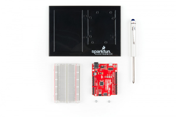
Qwiic Atmospheric Sensor (BME280) Hookup Guide

$
0
0

Qwiic Atmospheric Sensor (BME280) Hookup Guide a learn.sparkfun.com tutorial

Available online at: http://sfe.io/t929

Introduction

The new Qwiic Atmospheric Sensor (BME280) is an updated board revision of our Atmospheric Sensor Breakout- BME280 to make it Qwiic compatible. The Qwiic connector system reduces the hassle of interfacing to the sensor via I2C, by utilizing polarized cables that are simple to use. The BME280 is great for measuring humidity, temperature, and barometric pressure.

SparkFun Atmospheric Sensor Breakout - BME280 (Qwiic)

SparkFun Atmospheric Sensor Breakout - BME280 (Qwiic)

SEN-15440
$14.95

In addition, we now provide a Python library for compatibility with single board computer (SBC) platforms like the Raspberry Pi boards. The Arduino library is shared from the preexisting hardware. The examples below, will demonstrate how to use the Qwiic Atmospheric Sensor with a RedBoard Qwiic; and a Raspberry Pi with the Qwiic pHAT (and additional accessories) utilizing the Qwiic connection system.

Don't forget to check out this great video of Rob playing his sparxophone thanks to the help of the BME280!

Required Materials

The Qwiic Atmospheric Sensor does need a few additional items for you to get started. The RedBoard Qwiic is for the Arduino examples and the Qwiic pHAT is for the Raspberry Pi example (see note below). You may already have a few of these items, so feel free to modify your cart based on your needs. Additionally, there are also options that are available as well (click button below to toggle options).

SparkFun RedBoard Qwiic

SparkFun RedBoard Qwiic

DEV-15123
$19.95
2
SparkFun Qwiic Cable Kit

SparkFun Qwiic Cable Kit

KIT-15081
$7.95
1
SparkFun Qwiic pHAT for Raspberry Pi

SparkFun Qwiic pHAT for Raspberry Pi

DEV-15351
$5.95
Qwiic compatible microcontrollers:
SparkFun Thing Plus - ESP32 WROOM

SparkFun Thing Plus - ESP32 WROOM

WRL-14689
$20.95
5
SparkFun Thing Plus - SAMD51

SparkFun Thing Plus - SAMD51

DEV-14713
$19.95
1
SparkFun RedBoard Qwiic

SparkFun RedBoard Qwiic

DEV-15123
$19.95
2
SparkFun RedBoard Turbo - SAMD21 Development Board

SparkFun RedBoard Turbo - SAMD21 Development Board

DEV-14812
$24.95
2
In addition we also offer, Qwiic compatible stackable shields for microcontrollers and pHATs for single board computers (like the [Raspberry Pi boards](https://www.sparkfun.com/categories/395)) that don't include a Qwiic connector.
SparkFun Qwiic Shield for Arduino

SparkFun Qwiic Shield for Arduino

DEV-14352
$6.95
SparkFun Qwiic Shield for Photon

SparkFun Qwiic Shield for Photon

DEV-14477
$5.95
SparkFun Servo pHAT for Raspberry Pi

SparkFun Servo pHAT for Raspberry Pi

DEV-15316
$10.95
1
SparkFun Qwiic HAT for Raspberry Pi

SparkFun Qwiic HAT for Raspberry Pi

DEV-14459
$5.95
1
SparkFun Qwiic pHAT for Raspberry Pi

SparkFun Qwiic pHAT for Raspberry Pi

DEV-15351
$5.95
You will also need a Qwiic cable to connect to your BME280 Qwiic, choose a length that suits your needs.
Qwiic Cable - 100mm

Qwiic Cable - 100mm

PRT-14427
$1.50
Qwiic Cable - 500mm

Qwiic Cable - 500mm

PRT-14429
$1.95
Qwiic Cable - 200mm

Qwiic Cable - 200mm

PRT-14428
$1.50
Qwiic Cable - 50mm

Qwiic Cable - 50mm

PRT-14426
$0.95

Raspberry Pi Example: If you don't already have them, you will need a Raspberry Pi and standard peripherals. An example setup is listed below. (This sensor and the Python library have not been tested on the newly released Raspberry Pi 4 because we don't carry it in out catalog yet.)
Raspberry Pi 3 B+

Raspberry Pi 3 B+

DEV-14643
$39.95
29
pi-topCEED (Green)

pi-topCEED (Green)

KIT-14035
$114.95
4
Multimedia Wireless Keyboard

Multimedia Wireless Keyboard

WIG-14271
$29.95
3
Raspberry Pi™ - 16GB MicroSD NOOBS Card

Raspberry Pi™ - 16GB MicroSD NOOBS Card

COM-13945
3

Suggested Reading

If you're unfamiliar with jumper pads, I2C, Qwiic, or Python be sure to checkout some of these foundational tutorials. Also included, in this list, are past tutorials involving the BME280 sensor.

Serial Peripheral Interface (SPI)

SPI is commonly used to connect microcontrollers to peripherals such as sensors, shift registers, and SD cards.

Logic Levels

Learn the difference between 3.3V and 5V devices and logic levels.

I2C

An introduction to I2C, one of the main embedded communications protocols in use today.

How to Work with Jumper Pads and PCB Traces

Handling PCB jumper pads and traces is an essential skill. Learn how to cut a PCB trace, add a solder jumper between pads to reroute connections, and repair a trace with the green wire method if a trace is damaged.

Raspberry Pi SPI and I2C Tutorial

Learn how to use serial I2C and SPI buses on your Raspberry Pi using the wiringPi I/O library for C/C++ and spidev/smbus for Python.

Python Programming Tutorial: Getting Started with the Raspberry Pi

This guide will show you how to write programs on your Raspberry Pi using Python to control hardware.

Qwiic pHAT for Raspberry Pi Hookup Guide

Get started interfacing your Qwiic enabled boards with your Raspberry Pi. This Qwiic connects the I2C bus (GND, 3.3V, SDA, and SCL) on your Raspberry Pi to an array of Qwiic connectors.

Qwiic Kit for Raspberry Pi Hookup Guide

Get started with the CCS811, BME280, VCNL4040, and microOLED via I2C using the Qwiic system and Python on a Raspberry Pi! Take sensor readings from the enviroment and display them on the microOLED, serial terminal, or the cloud with Cayenne!

SparkFun BME280 Breakout Hookup Guide

A guide for connecting the BEM280 sensor to a microcontroller, and for using the Sparkfun Arduino library.

CCS811/BME280 (Qwiic) Environmental Combo Breakout Hookup Guide

Sense various environmental conditions such as temperature, humidity, barometric pressure, eCO2 and tVOCs with the CCS811 and BME280 combo breakout board.

RedBoard Qwiic Hookup Guide

This tutorial covers the basic functionality of the RedBoard Qwiic. This tutorial also covers how to get started blinking an LED and using the Qwiic system.

Qwiic Connect System

The Qwiic Atmospheric Sensor utilizes the Qwiic connect system. We recommend familiarizing yourself with the Logic Levels and I2C tutorials before using it. Click on the banner above to learn more about our Qwiic products.

Hardware Overview

Power

There is a power status LED to help make sure that your Qwiic Atmospheric Sensor is getting power. You can power the board either through the polarizedQwiic connector system or the breakout pins (3.3V and GND) provided. This Qwiic system is meant to use 3.3V, be sure that you are NOT using another voltage when using the Qwiic system.

Power LED, VDD, and GND
Annotated image of power LED along with VCC and GND connections. (Click to enlarge)

If you want to conserve power, there is an available jumper on the back of the board labeled LED to cut power to the LED (see Jumpers section below).

BME280 Sensor

The Bosch BME280 is the atmospheric sensor used on this board. It measures three different atmospheric properties: ambient temperature, (relative) humidity, and barometric pressure.

BME280 Sensor
Annotated image of BME280 sesnor. (Click to enlarge)

The BME280 uses three modes of operation: sleep mode, forced mode and normal mode. These modes dictate how the sensor performs measurement cycles. The BME280 can be interfaced via I2C (used with Qwiic connections) or SPI communication. In the table below, are some of the characteristics of the BME280 sensor from the datasheet:

CharacteristicDescription
Operating Voltage (VDD)1.71V to 3.6V (Default on Qwiic System: 3.3V)
Operational Modes**Sleep** (**Default**), Normal, and Forced (low power; single measurement)
Data Output 16-bit output from ADC
(*IIR filter and oversampling can increase this to 20-bit; excludes humidity data.)
Current Consumption (Typical) Sleep: 0.3 µA
Standby: 0.5 µA (inactive period of normal mode)
Humidity Measurements: 340 µA (peaks at 85°C)
Pressure Measurements: 714 µA (peaks at -40°C)
Temperature Measurements: 350 µA (peaks at 85°C)
Humidity Parameters Range: 0 to 100 %RH
Absolute Accuracy: ±3 %RH (from 20 - 80 %RH)
Resolution: 0.008 %RH
Forced Mode Current Consumption: 2.8 µA (max)
Pressure Parameters Range: 300 to 1100 hPa (30,000 - 110,000 Pa or approx. 4.35 - 15.95 PSI)
Absolute Accuracy: ±(1 - 1.7) hPa
Resolution: 0.18 Pa
Forced Mode Current Consumption: 4.2 µA (max)
Temperature Parameters Range: 0°C to 65°C (32°F to 149°F)
Absolute Accuracy: ±(0.5 - 1.5)°C
Resolution: 0.01°C
Forced Mode Current Consumption: 1.0 µA (typical)
I2C Address0x77 (Default) or 0x76

Modes of Operation

The BME280 offers three modes of operation:

  • Sleep mode (Default): No operation, all registers accessible, lowest power, selected after startup.
  • Forced mode (low power operation): Performs one measurement, store results and return to sleep mode.
  • Normal mode (active measurements): Perpetual cycling of measurements and inactive periods.

For more details, refer to sections 3.3.2-4 in the datasheet. Additionally, in section 3.5 the are a set of recommended sensor settings for various applications or operations.

Measurements

All measurements can be skipped or enabled. When enabled, there are several oversampling options; with oversampling, it is possible to reduce the noise.

For more details, refer to sections 3-4 in the datasheet.

Humidity

The resolution of the humidity measurement is fixed at 16-bit ADC output. A graph of the operational range for the humidity sensor (shaded in grey) is shown below; the sensor will not report and/or operate properly outside of this range.

Humidity sensor operational range
Operational range of the humidity sensor. (Click to enlarge)
Pressure and Temperature

For temperature and pressure readings, the resolution of the data will be dependent on if the infinite impulse response (IIR) filter is enabled and the oversampling setting register setting (osrs):

  • When the IIR filter is enabled, the measurement resolution is 20-bit.
  • When the IIR filter is disabled, the measurement resolution is [16 + (osrs–1)]-bit.
    • e.g. The temperature measurement is 18-bit when osrs_t is set to ‘3’.

(*Note: The temperature value depends on the PCB temperature, sensor element self-heating and ambient temperature and is typically just above ambient temperature.)

Data Analysis

Below are other important attributes of the sensor. For most users, this information is will either be outside their scope or trivial. However for those that are interested, these topics have been briefly summarized or quoted directly from the datasheet. For full details, please refer to the datasheet; additionally, some of the comments in the library may help.

Infinite Impulse Response Filter
  • It is recommended that the internal IIR filter be implemented to dampen rapid data fluctuations from external influences like wind blowing, closing doors, etc.
Noise
  • The expected noise in the measurement data is dependent on the oversampling setting. For pressure and temperature readings, it is also dependent on the IIR filter setting used.
Trimming Parameters
  • The trimming parameters are programmed into the devices’ non-volatile memory (NVM) during production and cannot be altered by users. These are used for the calibration/compensation parameters.
Compensation formulas
  • It is strongly advised (by the manufacturer) to use the API available from Bosch Sensortec to perform readout and compensation.

Qwiic or I2C

I2C Address

The BME280 has 2 available I2C addresses, which are set by the address pin, ADR. On the Qwiic Atmospheric sensor, the default slave address of the BME280 is 0x77 (HEX).

Default I2C Slave Address: 0x77

I2C Registers

The BME280 register (memory) map is detail in section 5.3 of the datasheet.

AddressDescription
0xD0ID: The chip identification number.
0xE0Soft Reset: If the value 0xB6 is written to the register, the device is reset using the complete power-on-reset procedure
0xF2ctrl_hum: Sets the humidity data acquisition options of the device. Changes to this register only become effective after a write operation to ctrl_meas.
0xF3 status: Indicate the status of the device.
Whether a conversion is running or the results have been transferred to the data registers.
Whether NVM data are being copied to image registers.
0xF4ctrl_meas: Sets the pressure and temperature data acquisition options of the device. The register needs to be written after changing ctrl_hum for the changes to become effective./td>
0xF5config: Sets the rate, filter and interface options of the device. Writes to the config register in normal mode may be ignored. In sleep mode writes are not ignored.
0xF7 to 0xF9press: The raw pressure measurement data.
0xFA to 0xFCtemp: The raw temperature measurement data.
0xFD to 0xFEhum: The raw humidity measurement data.
0xE1 to 0xF0
0x88 to 0xA1
Calibration Data: Holds Trimming Parameters.

Connections

The simplest way to use the Qwiic ADC is through the Qwiic connect system. The connectors are polarized for the I2C connection and power. (*They are tied to their corresponding breakout pins.)

Qwiic Connectors
Annotated image of the Qwiic connectors.

However, the board also provides six labeled breakout pins. You can connect these lines to the I2C bus of your microcontroller and power pins (3.3V and GND), if it doesn't have a Qwiic connector. Otherwise, the breakout pins can also be used for an SPI connection.

Breakout Pins
Annotated image of the breakout pins.
Pin LabelPin FunctionInput/OutputNotes
3.3VPower SupplyInput3.3V on Qwiic system (should be stable)
GNDGroundInputGround and Single-Ended Reference Voltage for ADC.
SDAI2C Data SignalBi-directionalBi-directional data line. Voltage should not exceed power supply (e.g. 3.3V).
SCLI2C Clock SignalInputMaster-controlled clock signal. Voltage should not exceed power supply (e.g. 3.3V).

SPI Connection

There are two options for an SPI connection 3-wire or 4-wire. For a 3-wire connection, users will need to cut the ADR jumper on the board. For a 4-wire connection users can cut the ADR, I2C, and CS jumpers to remove the load from the SPI lines, but it is not necessary. For more details, check out the notes in the schematic.

This tutorial will not go into detail about using an SPI connection as the Python library can only be used with an I2C connection. However, for users seeking an SPI setup, they can refer to the hookup guide for the original BME280 Sensor Breakout board.

Pin LabelPin FunctionInput/OutputNotes
3.3VPower SupplyInputSupply voltage for sensor. SHould be regulated between 1.8 and 3.6 V
GNDGroundInputGround
SCKClock SignalInputMaster-controlled clock signal. Voltage should not exceed power supply (max. 3.6V).
SDIData InInputData incoming to the BME280. Voltage should not exceed power supply (max. 3.6V).
SDOData OutOutputData coming from the BME280.
CS Chip Select
(or Slave Select)
InputUsed to select device communication on 4-wire connections (active low). Voltage should not exceed power supply (max. 3.6V).

Jumpers

Caution: Be careful when cutting traces, as not to unintentionally cut other traces.

There are 4 separate jumpers on the board for various hardware related functions. For more notes, check out the hardware schematic. Not sure how to modify a jumper? Read here!

LED Power

If you want to conserve power, the jumper labeled LED will allow users to isolate power to the power status indicator LED.

LED Jumper
Annotated image of LED jumper. (Click to enlarge)

I2C Address

If you want to change the I2C address for the sensor, the jumper labeled ADR will allow users to change the I2C address from the default (0x77) to 0x76.

ADR Jumper
Annotated image of ADR jumper. (Click to enlarge)

Pull-Up Resistors

There are two jumpers (well technically three) for the pull-up resistors attached to specific pins on the sensor.

I2C Pull-Ups

The first set of pull-up resistors are tied to the SDA and SCL lines for an I2C connection. Cutting the I2C jumper will remove the 4.7kΩ pull-up resistors from the I2C bus. If you have many devices on your I2C bus you may want to remove these jumpers. (When there are multiple devices on the bus with pull-up resistors, the equivalent parallel resistance may create too strong of a pull-up for the bus to operate correctly.)

I2C Jumper
Annotated image of I2C jumper. (Click to enlarge)
CS (and SPI) Pull-Ups

The last pull-up resistor is tied to CS pin for an SPI connection. Cutting the CS jumper will remove the 4.7kΩ pull-up resistor.

I2C Jumper
Annotated image of I2C jumper. (Click to enlarge)

Keep in mind that the rest of the SPI pins are shared with other pins (see the note above on the SPI connection or the schematic). For a 3-wire connection, users will need to cut the ADR jumper for the SDO line. For a 4-wire connection users can cut the ADR, I2C, and CS jumpers to remove the load from the SPI lines, but it is not necessary.

Hardware Assembly

Arduino Examples

With the Qwiic connector system, assembling the hardware is simple. All you need to do is connect your Qwiic Atmospheric Sensor (BME280) to the RedBoard Qwiic with a Qwiic cable. Otherwise, you can use the I2C pins of your microcontroller; just be aware of logic levels.

Hardware assembly with RedBoard Qwiic
RedBoard Qwiic connected the Qwiic Atmospheric Sensor with a Qwiic cable.

Note: This tutorial assumes you are familiar with Arduino products and you are using the latest stable version of the Arduino IDE on your desktop. If this is your first time using the Arduino IDE, please review our tutorial on installing the Arduino IDE.

Raspberry Pi Example

Note: This sensor and the Python library have not been tested on the newly released Raspberry Pi 4 because we don't carry it in out catalog yet.

With the Qwiic connector system, assembling the hardware is simple. In addition to the Qwiic Atmospheric Sensor (BME280), you will need: a Qwiic cable, a SparkFun Qwiic pHAT for Raspberry Pi, and a Raspberry Pi setup with the Raspbian OS, monitor, and standard peripherals. (*If you are unfamiliar with the Qwiic pHAT, you can find the Hookup Guide here.)

Hardware assembly with Raspberry Pi 3B+ with Qwiic pHAT
Raspberry Pi 3B+ connected the Qwiic Atmospheric Sensor with a Qwiic pHAT and Qwiic cable.
(*A 4-40 screw and nut were used to mount the senor to the pHAT.)

Alternatively, you can also use a Raspberry Pi 3 and the Qwiic HAT instead.

Hardware assembly with Raspberry Pi 3B with Qwiic HAT
Raspberry Pi 3 connected the Qwiic Atmospheric Sensor with a Qwiic HAT and Qwiic cable.

Note: This tutorial assumes you are familiar with using a Raspberry Pi and you have the latest (full... with recommended software) version of Raspbian OS your Raspberry Pi. You can download the latest version of the Raspbian OS from the Raspberry Pi Foundation website. As of Feb. 13th 2019, we recommend the Raspbian Stretch with desktop and recommended software option.

If this is your first time using a Raspberry Pi, please head over to the Raspberry Pi Foundation website to use their quickstart guides. We have listed a few of them here:

  1. Setting up your Raspberry Pi
  2. Using your Raspberry Pi
  3. Documentation:
  4. Setup Documentation
    Installation Documentation
    Raspbian Documentation
    SD card Documentation

Arduino Library Overview

Note: This example assumes you are using the latest version of the Arduino IDE on your desktop. If this is your first time using Arduino, please review our tutorial on installing the Arduino IDE. If you have not previously installed an Arduino library, please check out our installation guide.

We've written a library to easily get setup and take readings from the Qwiic Atmospheric Sensor. However, before we jump into getting data from the sensor, let's take a closer look at the available functions in the library. You can install this library through the Arduino Library Manager. Search for SparkFun BME280 Arduino Library and you should be able to install the latest version. If you prefer manually downloading the libraries from the GitHub repository, you can grab them here:

Let's get started by looking at the functions that set up the Qwiic Atmospheric Sensor:

Class

In the global scope, construct your sensor object (such as mySensor or pressureSensorA) without arguments.

BME280 mySensor;

Object Parameters and setup()

Rather that passing a bunch of data to the constructor, configuration is accomplished by setting the values of the BME280 type in the setup() function. They are exposed by being public: so use the myName.aVariable = someValue; syntax.

Settable variables of the class BME280:

language:c
//Main Interface and mode settings
uint8_t commInterface;
uint8_t I2CAddress;
uint8_t chipSelectPin;

uint8_t runMode;
uint8_t tStandby;
uint8_t filter;
uint8_t tempOverSample;
uint8_t pressOverSample;
uint8_t humidOverSample;

Functions

.begin();
Initialize the operation of the BME280 module with the following steps:

  • Starts up the wiring library for I2C by default
  • Checks/Validates BME280 chip ID
  • Reads compensation data
  • Sets default settings from table
  • Sets operational mode to Normal Mode
Output: uint8_t

Returns the BME280 chip ID stored in the ID register.

.begin() Needs to be run once during the setup, or after any settings have been modified. In order to let the sensor's configuration take place, the BME280 requires a minimum time of about 2 ms in the sketch before you take data.

.beginSPI(uint8_t csPin);
Begins communication with the BME280 over an SPI connection.

Input: uint8_t

csPin: Digital pin used for the CS.

Output: Boolean

True: Connected to sensor.
False: Unable to establish connection.

.beginI2C(TwoWire &wirePort); or .beginI2C(SoftwareWire &wirePort);
Begins communication with the BME280 over an I2C connection. If #ifdef SoftwareWire_h is defined, then a software I2C connection is used.

Input: &wirePort

&wirePort: Port for the I2C connection.

Output: Boolean

True: Connected to sensor.
False: Unable to establish connection.

.setMode(uint8_t mode);
Sets the operational mode of the sensor. (For more details, see section 3.3 of the datasheet.)

Input: uint8_t

0: Sleep Mode
1: Forced Mode
2: Normal Mode

.getMode();
Returns the operational mode of the sensor.

Output: uint8_t

0: Sleep Mode
1: Forced Mode
2: Normal Mode

.setStandbyTime(uint8_t timeSetting);
Sets the standby time of the cycle time. (For more details, see section 3.3 and Table 27 of the datasheet.)

Input: uint8_t

0: 0.5ms
1: 62.5ms
2: 125ms
3: 250ms
4: 500ms
5: 1000ms
6: 10ms
7: 20ms

.setFilter(uint8_t filterSetting)
Sets the time constant of the IIR filter, which slows down the response time of the sensor inputs based on the number of samples required. (For more details, see section 3.4.4, Table 6, and Figure 7 of the datasheet.)

Input: uint8_t

0: filter off
1: coefficient of 2
2: coefficient of 4
3: coefficient of 8
4: coefficient of 16

.setTempOverSample(uint8_t overSampleAmount);
Sets the oversampling option (osrs_t) for the temperature measurements. (Directly influences the noise and resolution of the data.)

Input: uint8_t

0: turns off temperature sensing
1: oversampling ×1
2: oversampling ×2
4: oversampling ×4
8: oversampling ×8
16: oversampling ×16
Other: Bad Entry, sets to oversampling ×1 by default.

Note: Yes, we do know there is a spelling error in the name of the method. It will get corrected in the next library update.

.setPressureOverSample(uint8_t overSampleAmount);
Sets the oversampling option (osrs_p) for the pressure measurements. (Directly influences the noise and resolution of the data.)

Input: uint8_t

0: turns off pressure sensing
1: oversampling ×1
2: oversampling ×2
4: oversampling ×4
8: oversampling ×8
16: oversampling ×16
Other: Bad Entry, sets to oversampling ×1 by default.

.setHumidityOverSample(uint8_t overSampleAmount);
Sets the oversampling option (osrs_h) for the humidity measurements. (Directly influences the noise of the data.)

Input: uint8_t

0: turns off humidity sensing
1: oversampling ×1
2: oversampling ×2
4: oversampling ×4
8: oversampling ×8
16: oversampling ×16
Other: Bad Entry, sets to oversampling ×1 by default.

.setI2CAddress(uint8_t address);
Changes the I2C address stored in the library to access the sensor.

Input: uint8_t

address: The new I2C address.

.isMeasuring();
Checks the measuring bit of the status register for if the device is taking measurement.

Output: Boolean

True: A conversion is running.
False: The results have been transferred to the data registers.

.reset();
Soft resets the sensor. (If called, the begin function must be called before using the sensor again.)

.readFloatPressure();
Reads raw pressure data stored in register and applies output compensation (For more details on the data compensation, see section 4.2 of the datasheet.)

Output: float

Returns pressure in kPa.

.readFloatHumidity();
Reads raw humidity data stored in register and applies output compensation (For more details on the data compensation, see section 4.2 of the datasheet.)

Output: float

Returns humidity in %RH.

.readTempC();
Reads raw temperature data stored in register and applies output compensation (For more details on the data compensation, see section 4.2 of the datasheet.)

Output: float

Returns temperature in Celsius.

.readTempF();
Reads raw temperature data stored in register and applies output compensation (For more details on the data compensation, see section 4.2 of the datasheet.)

Output: float

Returns temperature in Fahrenheit.

Arduino Example Code

The examples can be found in the the drop-down menu (File > Examples > SparkFun BME280 > ...) of the Arduino IDE. They can also be downloaded from the GitHub repositoryand then ran on their own. These are just a few samples of the available selection of examples.

Below are a sample readouts from the Serial Monitor for each of the examples. The baud rate for all of the examples default to 9600 baud.

Example 1: Basic Readings

This basic example configures an BME280 on the I2C bus and reports out the data.

Example 1 Readout

Expected readout from Example 1, where the basic readings are displayed

Example 3: CSV Output

If you want to use the BME280 to record data as a function of time, this example is for you! It outputs text as CSV (comma separated vales) that can be copy-pasted into a textfile or spreadsheet app for graphing.

A note on accuracy: This sketch use "delay(50);" to wait 50ms between reads. The units of the 'sample' column are in (50ms + time-to-read) periods.

Example 3 Readout

Expected readout from Example 3, where the first few lines show the generated CSV.

Example 5: Read All Registers

Here's an example that prints out the registers as well as the internally concatenated calibration words. It can be used to check the state of the BME280 after a particular configuration or can be implanted in your own sketch where you need to debug.

Example 5 Readout

Expected readout from Example 5, where the full contents of memory are shown and a calculated pressure altitude.

Example 6: Low Power

Here is an example with a low power operation, utilizing the sleep mode functionality. This is similar to Example 1, except the sensor is in sleep mode and data is taken at specific intervals.

Example 6 Readout

Expected readout from Example 6.

Python Library Overview

Note: This sensor and the Python library have not been tested on the newly released Raspberry Pi 4 because we don't carry it in out catalog yet.

Note: This example assumes you are using the latest version of Python (2 or 3). If this is your first time using Python or I2C hardware on a Raspberry Pi, please checkout our tutorial on Python Programming with the Raspberry Pi and the Raspberry Pi SPI and I2C Tutorial.

We've written a library to easily get setup and take readings from the Qwiic Atmospheric Sensor. However, before we jump into getting data from the sensor, let's take a closer look at the available functions in the library. You can install the sparkfun-qwiic-bme280 library package hosted by PyPi. However, if you prefer to manually download and build the libraries from the GitHub repository, you can grab them here (*Please be aware of any package dependencies. You can also check out the repository documentation page, hosted on Read the Docs.):

Installation

Note: Don't forget to double check that the hardware I2C connection is enabled on your Raspberry Pi or other single board computer.

PyPi Installation

This repository is hosted on PyPi as the sparkfun-qwiic-bme280 package. On systems that support PyPi installation via pip (use pip3 for Python 3) is simple, using the following commands:

For all users (note: the user must have sudo privileges):

sudo pip install sparkfun-qwiic-bme280

For the current user:

pip install sparkfun-qwiic-bme280

Local Installation

To install, make sure the setuptools package is installed on the system.

Direct installation at the command line:

python setup.py install

To build a package for use with pip:

python setup.py sdist

A package file is built and placed in a subdirectory called dist. This package file can be installed using pip.

cd dist
pip install sparkfun_qwiic_bme280-<version>.tar.gz

Library Operation

Below is a description of the basic functionality of the Python library. This includes the library organization, built-in methods, and their inputs and/or outputs. For more details on how the library works, check out the source code and the sensor datasheet.

Dependencies

This library has a very few dependencies in the code, listed below:

language:python
from __future__ import print_function
import math
import qwiic_i2c

Default Variables

The default variables, in the code, for this library are listed below:

language:python
#The name of this device
_DEFAULT_NAME = "Qwiic BME280"

_AVAILABLE_I2C_ADDRESS = [0x77, 0x76]

#Default Setting Values
_settings = {"runMode" : 3,         \
            "tStandby" : 0,         \
            "filter"   : 0,         \
            "tempOverSample"  : 1,  \
            "pressOverSample" : 1,  \
            "humidOverSample" : 1,  \
            "tempCorrection"  : 0.0}

#define our valid chip IDs
_validChipIDs = [0x58, 0x60]

Class

QwiicBme280() or QwiicBme280(i2caddr)
This library operates as a class object, allowing new instances of that type to be made. An __init__() constructor is used that creates a connection to an I2C device over the I2C bus using the default or specified I2C address.

The Constructor

A constructor is a special kind of method used to initialize (assign values to) the data members needed by the object when it is created.

__init__(address=None, i2c_driver=None):

Input: value
The value of the device address. If not defined, the library will use the default I2C address (0x77) stored under _AVAILABLE_I2C_ADDRESS variable. The other available address is 0x76 (set by the jumper on the bottom side of the board).
Input: i2c_driver
Loads the specified I2C driver; by default the Qwiic I2C driver is used: qwiic_i2c.getI2CDriver(). Users should use the default I2C driver and leave this field blank.
Output: Boolean

True: Connected to I2C device on the default (or specified) address.
False: No device found or connected.

Functions

A function that is an attribute of the class, which defines a method for instances of that class. In simple terms, they are objects for the operations (or methods) of the class.

.is_connected()
Determines if the BME280 device is connected to the system.

Output: Boolean

True: Connected to I2C device on the default (or specified) address.
False: No device found or connected.

.begin()
Initialize the operation of the BME280 module with the following steps:

  • Checks/Validates BME280 chip ID
  • Reads compensation data
  • Sets default settings from table
  • Sets operational mode to Normal Mode
Output: Boolean

True: The initialization was successful.
False: Invalid chip ID.

.set_mode(mode)
Sets the operational mode of the sensor. .mode is also a property that can be set with the instance variables: MODE_SLEEP, MODE_FORCED, or MODE_NORMAL. (For more details, see section 3.3 of the datasheet.)

Input: value

0: Sleep Mode
1: Forced Mode
2: Normal Mode

.get_mode()
Returns the operational mode of the sensor.

Output: integer

0: Sleep Mode
1: Forced Mode
2: Normal Mode

.set_standby_time(timeSetting)
Sets the standby time of the cycle time. (For more details, see section 3.3 and Table 27 of the datasheet.)

Input: value

0: 0.5ms
1: 62.5ms
2: 125ms
3: 250ms
4: 500ms
5: 1000ms
6: 10ms
7: 20ms

.set_filter(filterSetting)
Sets the time constant of the IIR filter, which slows down the response time of the sensor inputs based on the number of samples required. (For more details, see section 3.4.4, Table 6, and Figure 7 of the datasheet.)

Input: value

0: filter off
1: coefficient of 2
2: coefficient of 4
3: coefficient of 8
4: coefficient of 16

.set_tempature_oversample(overSampleAmount)
Sets the oversampling option (osrs_t) for the temperature measurements. (Directly influences the noise and resolution of the data.)

Input: value

0: turns off temperature sensing
1: oversampling ×1
2: oversampling ×2
4: oversampling ×4
8: oversampling ×8
16: oversampling ×16
Other: Bad Entry, sets to oversampling ×1 by default.

Note: Yes, we do know there is a spelling error in the name of the method. It will get corrected in the next library update.

.set_pressure_oversample(overSampleAmount)
Sets the oversampling option (osrs_p) for the pressure measurements. (Directly influences the noise and resolution of the data.)

Input: value

0: turns off pressure sensing
1: oversampling ×1
2: oversampling ×2
4: oversampling ×4
8: oversampling ×8
16: oversampling ×16
Other: Bad Entry, sets to oversampling ×1 by default.

.set_humidity_oversample(overSampleAmount)
Sets the oversampling option (osrs_h) for the humidity measurements. (Directly influences the noise of the data.)

Input: value

0: turns off humidity sensing
1: oversampling ×1
2: oversampling ×2
4: oversampling ×4
8: oversampling ×8
16: oversampling ×16
Other: Bad Entry, sets to oversampling ×1 by default.

.is_measuring()
Checks the measuring bit of the status register for if the device is taking measurement.

Output: Boolean

True: A conversion is running.
False: The results have been transferred to the data registers.

.reset()
Soft resets the sensor. (If called, the begin method must be called before using the sensor again.)

.read_pressure()
Reads raw pressure data stored in register and applies output compensation (For more details on the data compensation, see section 4.2 of the datasheet.)

Output: float

Returns pressure in Pa.

.read_humidity()
Reads raw humidity data stored in register and applies output compensation (For more details on the data compensation, see section 4.2 of the datasheet.)

Output: float

Returns humidity in %RH.

.get_temperature_celsius()
Reads raw temperature data stored in register and applies output compensation (For more details on the data compensation, see section 4.2 of the datasheet.)

Output: float

Returns temperature in Celsius.

.get_temperature_fahrenheit()
Reads raw temperature data stored in register and applies output compensation (For more details on the data compensation, see section 4.2 of the datasheet.)

Output: float

Returns temperature in Fahrenheit.

Python Example Code

The following examples are available in the GitHub repository. To run the examples, simple download or copy the code into a file. Then, open/save the example file (if needed) and execute the code in your favorite Python IDE.

For example, with the default Python IDLE click Run > Run Module or use the F5 key. To terminate the example use the Ctrl + C key combination.

Note: Yes, there is an altitude_feet function in the library that is available. However, that content is omitted from the Library Overview section due to the amount of confusion that was generated with the previous hookup guide. Some users were misinterpreting the reported "altitude" from the function as an exact value; when it actually is calculated from the (barometric) pressure measurement to report the equivalentpressure altitude based on an atmospheric model. If you want more details on this subject, look into how an altimeter works.

Example 1

This example uses the default configuration settings for the sensor. The temperature (°F), humidity (%RH), pressure (Pa), and calculated pressure altitude (ft.) are reported repeatedly.

language:python
#!/usr/bin/env python
#-----------------------------------------------------------------------------
# qwiic_env_bme280_ex1.py
#
# Simple Example for the Qwiic BME280 Device
#------------------------------------------------------------------------
#
# Written by  SparkFun Electronics, May 2019
# 
# This python library supports the SparkFun Electroncis qwiic 
# qwiic sensor/board ecosystem on a Raspberry Pi (and compatable) single
# board computers. 
#
# More information on qwiic is at https://www.sparkfun.com/qwiic
#
# Do you like this library? Help support SparkFun. Buy a board!
#
#==================================================================================
# Copyright (c) 2019 SparkFun Electronics
#
# Permission is hereby granted, free of charge, to any person obtaining a copy 
# of this software and associated documentation files (the "Software"), to deal 
# in the Software without restriction, including without limitation the rights 
# to use, copy, modify, merge, publish, distribute, sublicense, and/or sell 
# copies of the Software, and to permit persons to whom the Software is 
# furnished to do so, subject to the following conditions:
#
# The above copyright notice and this permission notice shall be included in all 
# copies or substantial portions of the Software.
#
# THE SOFTWARE IS PROVIDED "AS IS", WITHOUT WARRANTY OF ANY KIND, EXPRESS OR 
# IMPLIED, INCLUDING BUT NOT LIMITED TO THE WARRANTIES OF MERCHANTABILITY, 
# FITNESS FOR A PARTICULAR PURPOSE AND NONINFRINGEMENT. IN NO EVENT SHALL THE 
# AUTHORS OR COPYRIGHT HOLDERS BE LIABLE FOR ANY CLAIM, DAMAGES OR OTHER 
# LIABILITY, WHETHER IN AN ACTION OF CONTRACT, TORT OR OTHERWISE, ARISING FROM, 
# OUT OF OR IN CONNECTION WITH THE SOFTWARE OR THE USE OR OTHER DEALINGS IN THE 
# SOFTWARE.
#==================================================================================
# Example 1
#

from __future__ import print_function
import qwiic_bme280
import time
import sys

def runExample():

    print("\nSparkFun BME280 Sensor  Example 1\n")
    mySensor = qwiic_bme280.QwiicBme280()

    if mySensor.connected == False:
        print("The Qwiic BME280 device isn't connected to the system. Please check your connection", \
            file=sys.stderr)
        return

    mySensor.begin()

    while True:
        print("Humidity:\t%.3f" % mySensor.humidity)

        print("Pressure:\t%.3f" % mySensor.pressure)    

        print("Altitude:\t%.3f" % mySensor.altitude_feet)

        print("Temperature:\t%.2f" % mySensor.temperature_fahrenheit)       

        print("")

        time.sleep(1)


if __name__ == '__main__':
    try:
        runExample()
    except (KeyboardInterrupt, SystemExit) as exErr:
        print("\nEnding Example 1")
sys.exit(0)

Example 1
Expected readout from Example 1.

Experiment 4

This example configures the settings for the sensor before the temperature (°F), humidity (%RH), pressure (Pa), and calculated pressure altitude (ft.) are reported repeatedly.

language:python
#!/usr/bin/env python
#-----------------------------------------------------------------------------
# qwiic_env_bme280_ex4.py
#
# Simple Example for the Qwiic BME280 Device
#------------------------------------------------------------------------
#
# Written by  SparkFun Electronics, May 2019
# 
# This python library supports the SparkFun Electroncis qwiic 
# qwiic sensor/board ecosystem on a Raspberry Pi (and compatable) single
# board computers. 
#
# More information on qwiic is at https:# www.sparkfun.com/qwiic
#
# Do you like this library? Help support SparkFun. Buy a board!
#
#==================================================================================
# Copyright (c) 2019 SparkFun Electronics
#
# Permission is hereby granted, free of charge, to any person obtaining a copy 
# of this software and associated documentation files (the "Software"), to deal 
# in the Software without restriction, including without limitation the rights 
# to use, copy, modify, merge, publish, distribute, sublicense, and/or sell 
# copies of the Software, and to permit persons to whom the Software is 
# furnished to do so, subject to the following conditions:
#
# The above copyright notice and this permission notice shall be included in all 
# copies or substantial portions of the Software.
#
# THE SOFTWARE IS PROVIDED "AS IS", WITHOUT WARRANTY OF ANY KIND, EXPRESS OR 
# IMPLIED, INCLUDING BUT NOT LIMITED TO THE WARRANTIES OF MERCHANTABILITY, 
# FITNESS FOR A PARTICULAR PURPOSE AND NONINFRINGEMENT. IN NO EVENT SHALL THE 
# AUTHORS OR COPYRIGHT HOLDERS BE LIABLE FOR ANY CLAIM, DAMAGES OR OTHER 
# LIABILITY, WHETHER IN AN ACTION OF CONTRACT, TORT OR OTHERWISE, ARISING FROM, 
# OUT OF OR IN CONNECTION WITH THE SOFTWARE OR THE USE OR OTHER DEALINGS IN THE 
# SOFTWARE.
#==================================================================================
# Example 4 - port of the Arduino example 4
#

from __future__ import print_function
import qwiic_bme280
import time
import sys

def runExample():

    print("\nSparkFun BME280 Sensor  Example 4\n")
    mySensor = qwiic_bme280.QwiicBme280()

    if mySensor.connected == False:
        print("The Qwiic BME280 device isn't connected to the system. Please check your connection", \
            file=sys.stderr)
        return

    mySensor.begin()

    # setup the sensor
    mySensor.filter = 1         # 0 to 4 is valid. Filter coefficient. See 3.4.4
    mySensor.standby_time = 0   # 0 to 7 valid. Time between readings. See table 27.

    mySensor.over_sample = 1            # 0 to 16 are valid. 0 disables temp sensing. See table 24.
    mySensor.pressure_oversample = 1    # 0 to 16 are valid. 0 disables pressure sensing. See table 23.
    mySensor.humidity_oversample = 1    # 0 to 16 are valid. 0 disables humidity sensing. See table 19.
    mySensor.mode = mySensor.MODE_NORMAL # MODE_SLEEP, MODE_FORCED, MODE_NORMAL is valid. See 3.3

    while True:
        print("Humidity:\t%.3f" % mySensor.humidity)

        print("Pressure:\t%.3f" % mySensor.pressure)    

        print("Altitude:\t%.3f" % mySensor.altitude_feet)

        print("Temperature:\t%.2f\n" % mySensor.temperature_fahrenheit)

        time.sleep(1)


if __name__ == '__main__':
    try:
        runExample()
    except (KeyboardInterrupt, SystemExit) as exErr:
        print("\nEnding Example 4")
sys.exit(0)

Example 4
Expected readout from Example 4.

Experiment 5

This last example reports configuration the settings and calibration values from the memory map. Then, the temperature (°F), humidity (%RH), pressure (Pa), and calculated pressure altitude (ft.) are reported repeatedly.

language:python
#!/usr/bin/env python
#-----------------------------------------------------------------------------
# qwiic_env_bme280_ex5.py
#
# Simple Example for the Qwiic BME280 Device
#------------------------------------------------------------------------
#
# Written by  SparkFun Electronics, May 2019
# 
# This python library supports the SparkFun Electroncis qwiic 
# qwiic sensor/board ecosystem on a Raspberry Pi (and compatable) single
# board computers. 
#
# More information on qwiic is at https:# www.sparkfun.com/qwiic
#
# Do you like this library? Help support SparkFun. Buy a board!
#
#==================================================================================
# Copyright (c) 2019 SparkFun Electronics
#
# Permission is hereby granted, free of charge, to any person obtaining a copy 
# of this software and associated documentation files (the "Software"), to deal 
# in the Software without restriction, including without limitation the rights 
# to use, copy, modify, merge, publish, distribute, sublicense, and/or sell 
# copies of the Software, and to permit persons to whom the Software is 
# furnished to do so, subject to the following conditions:
#
# The above copyright notice and this permission notice shall be included in all 
# copies or substantial portions of the Software.
#
# THE SOFTWARE IS PROVIDED "AS IS", WITHOUT WARRANTY OF ANY KIND, EXPRESS OR 
# IMPLIED, INCLUDING BUT NOT LIMITED TO THE WARRANTIES OF MERCHANTABILITY, 
# FITNESS FOR A PARTICULAR PURPOSE AND NONINFRINGEMENT. IN NO EVENT SHALL THE 
# AUTHORS OR COPYRIGHT HOLDERS BE LIABLE FOR ANY CLAIM, DAMAGES OR OTHER 
# LIABILITY, WHETHER IN AN ACTION OF CONTRACT, TORT OR OTHERWISE, ARISING FROM, 
# OUT OF OR IN CONNECTION WITH THE SOFTWARE OR THE USE OR OTHER DEALINGS IN THE 
# SOFTWARE.
#==================================================================================
# Example 5 - port of the Arduino example 5
#

from __future__ import print_function
import qwiic_bme280
import time
import sys

def runExample():

    print("\nSparkFun BME280 Sensor  Example 5\n")
    mySensor = qwiic_bme280.QwiicBme280()

    if mySensor.connected == False:
        print("The Qwiic BME280 device isn't connected to the system. Please check your connection", \
            file=sys.stderr)
        return

    mySensor.begin()

    print("ID(0xD0): 0x%.2x" % mySensor._i2c.readByte(mySensor.address, mySensor.BME280_CHIP_ID_REG))
    print("Reset register(0xE0): 0x%.2x" % mySensor._i2c.readByte(mySensor.address, mySensor.BME280_RST_REG))
    print("ctrl_meas(0xF4): 0x%.2x" % mySensor._i2c.readByte(mySensor.address, mySensor.BME280_CTRL_MEAS_REG))
    print("ctrl_hum(0xF2): 0x%.2x\n" % mySensor._i2c.readByte(mySensor.address, mySensor.BME280_CTRL_HUMIDITY_REG))

    print("Displaying all regs:")
    memCounter = 0x80
    for row in range(8,16):
        print("0x%.2x 0:" % row, end='')
        for column in range(0,16):
            tempReadData = mySensor._i2c.readByte(mySensor.address, memCounter)
            print("0x%.2x " % tempReadData, end='')

            memCounter += 1
        print("")


    print("Displaying concatenated calibration words:")
    print("dig_T1, uint16: %d" % mySensor.calibration["dig_T1"])
    print("dig_T2, int16: %d" % mySensor.calibration["dig_T2"])
    print("dig_T3, int16: %d" % mySensor.calibration["dig_T3"])
    print("dig_P1, uint16: %d" % mySensor.calibration["dig_P1"])
    print("dig_P2, int16: %d" % mySensor.calibration["dig_P2"])
    print("dig_P3, int16: %d" % mySensor.calibration["dig_P3"])
    print("dig_P4, int16: %d" % mySensor.calibration["dig_P4"])
    print("dig_P5, int16: %d" % mySensor.calibration["dig_P5"])
    print("dig_P6, int16: %d" % mySensor.calibration["dig_P6"])
    print("dig_P7, int16: %d" % mySensor.calibration["dig_P7"])
    print("dig_P8, int16: %d" % mySensor.calibration["dig_P8"])
    print("dig_P9, int16: %d" % mySensor.calibration["dig_P9"])
    print("dig_H1, uint8: %d" % mySensor.calibration["dig_H1"])
    print("dig_H2, int16: %d" % mySensor.calibration["dig_H2"])
    print("dig_H3, uint8: %d" % mySensor.calibration["dig_H3"])
    print("dig_H4, int16: %d" % mySensor.calibration["dig_H5"])
    print("dig_H6, int8: %d" % mySensor.calibration["dig_H6"])
    while True:

        print("Humidity:\t%.3f" % mySensor.humidity)

        print("Pressure:\t%.3f" % mySensor.pressure)    

        print("Altitude:\t%.3f" % mySensor.altitude_feet)

        print("Temperature:\t%.2f\n" % mySensor.temperature_fahrenheit)

        time.sleep(1)

if __name__ == '__main__':
    try:
        runExample()
    except (KeyboardInterrupt, SystemExit) as exErr:
        print("\nEnding Example 5")
sys.exit(0)

Example 5
Expected readout from Example 5.

Troubleshooting Tips

Here are a few tips for troubleshooting this device.

Power

If you are not using the Qwiic system, make sure your supply voltage is within the electrical specifications of the BME280.

No Available Devices

Double check your connections. On a Raspberry Pi, you may get this is indicated with an OSError: [Errno 121] Remote I/O error readout.

On a Raspberry Pi, also make sure that the I2C hardware is enabled. This is usually indicated with an Error: Failed to connect to I2C bus 1. readout.

SPI Setup

As mentioned earlier, this tutorial does not go into detail about using an SPI connection as the Python library can only be used with an I2C connection. However, for users seeking an SPI setup, they can refer to the hookup guide for the original BME280 Sensor Breakout board.

If you still have questions or issues with this product, please create a post on our forum under the Qwiic Atmospheric Sensor (SEN-15440): Questions and Issues topic.

Resources and Going Further

For more product information, check out the resources below:

Need some inspiration for your next project? Check out some of these other Qwiic product tutorials:

SparkFun GPS Breakout - XA1110 (Qwiic) Hookup Guide

Figure out where in the world you are with the Qwiic SparkFun GPS Breakout - XA1110.

Qwiic Magnetometer (MLX90393) Hookup Guide

Figure out how magnetic fields are oriented, all without having to solder a thing.

Qwiic UV Sensor (VEML6075) Hookup Guide

Learn how to connect your VEML6075 UV Sensor and figure out just when you should put some sunscreen on.

ESP32 Thing Plus Hookup Guide

Hookup guide for the ESP32 Thing Plus using the ESP32 WROOM's WiFi/Bluetooth system-on-chip in Arduino.

Need some inspiration for your next project? Check out some of these other weather related tutorials:

Photon Remote Water Level Sensor

Learn how to build a remote water level sensor for a water storage tank and how to automate a pump based off the readings!

Si7021 Humidity and Temperature Sensor Hookup Guide

The Si7021 humidity and temperature sensor is an easy to use, digital, low-cost sensor to aid you in all your environment sensing needs.

Weather Meter Hookup Guide

How to assemble your very own weather meter!

SparkFun gator:environment Hookup Guide

The gator:environment combines two I2C sensors for temperature, humidity, pressure, eCO2, and eTVOC values. This tutorial will get you started using the gator:environment with the micro:bit platform.
Python Logo

learn.sparkfun.com | CC BY-SA 3.0 | SparkFun Electronics | Niwot, Colorado
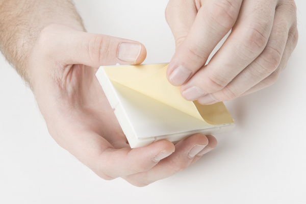
XBee3 Thing Plus Hookup Guide

$
0
0

XBee3 Thing Plus Hookup Guide a learn.sparkfun.com tutorial

Available online at: http://sfe.io/t745

Introduction

Who doesn't love a Bee? With these 2 versions of SparkFun's XBee3 Thing Plus - the XBee3 Thing Plus (u.FL) and the XBee3 Thing Plus (PCB Antenna), we've taken DIGI's XBEE3 802.15.4 and plopped it into the Thing Plus footprint and the result has us all abuzz. For all intents and purposes, the 2 variants are the same board - the difference being in the antenna.

SparkFun Thing Plus - XBee3 Micro (U.FL)

SparkFun Thing Plus - XBee3 Micro (U.FL)

WRL-15435
$49.95
SparkFun Thing Plus - XBee3 Micro (Chip Antenna)

SparkFun Thing Plus - XBee3 Micro (Chip Antenna)

WRL-15454
$49.95

Required Materials

To follow along with this tutorial, you will need the following materials. You may not need everything, depending on what you have. Add it to your cart with your choice of the XBee3, read through the guide, and adjust the cart as necessary.

Suggested Reading

If you aren’t familiar with the following concepts, we recommend checking out these tutorials before continuing.

How to Solder: Through-Hole Soldering

This tutorial covers everything you need to know about through-hole soldering.

Serial Terminal Basics

This tutorial will show you how to communicate with your serial devices using a variety of terminal emulator applications.

Exploring XBees and XCTU

How to set up an XBee using your computer, the X-CTU software, and an XBee Explorer interface board.

MicroPython Programming Tutorial: Getting Started with the ESP32 Thing

MicroPython is an implementation and subset of the Python 3 programming language that can be used on microcontrollers. This guide will walk you through writing MicroPython programs for the ESP32 Thing development board.

Hardware Overview

Whether you're using the u.fl version or trace antenna version , the XBee3 Thing Plus is chock full of functionality. The XBee3 module itself measures 13 mm x 19 mm and supports multiple protocols, including ZigBee, 802.154, DigiMesh, and BLE. Add into that the capabilities of SparkFun's Thing Plus and we're looking at an amazing amount of functionality.

XBee3 Features

  • Voltage Range: 2.1-3.6V
  • 2μA Power-down current
  • 1MB of flash, 128kB of RAM
  • +8dBm transmitting power (Up to 135mA)
  • -103dBm receiving sensitivity (17mA)
  • Supported protocols: 802.15.4, Bluetooth v4.0, Zigbee
  • RF Data Rate: 250Kbps
  • UART Data Rate: Up to 1Mbps
  • Indoor range: Up to 200ft (60m)
  • Outdoor (Line-Of-Sight): Up to 4000ft (1200m)

Board Highlight

Click the image for a closer look.

Peripherals and I/O

The XBee3 Thing Plus features your standard fare of hardware peripherals including:

  • 20 general purpose input/output pins
  • Up to four 10-bit analog to digital converter (ADC) channels (see note 1)
  • Up to two 10-bit pulse width modulation (PWM) channels (see note 2)
  • UART
  • I2C
  • SPI (see note 3)
Note:

1. There are three dedicated ADC channels, with the fourth connected to IO pin 1/SCL if I2C is not being used.

2. There is a dedicated PWM channel connected to IO pin 10, with the second connected to IO pin 11/SDA if I2C is not being used.

3. SPI is currently still under development from Digi and is not yet supported in MicroPython.

Powering the XBee3 Thing Plus

The two main power inputs to the XBee3 Thing Plus are USB and a single-cell lithium-polymer (LiPo battery. If both USB and the LiPo are plugged into the board, the onboard charge controller will charge the LiPo battery at a rate up to 500mA.

⚡ The XBee3's operating voltage range is 2.1 to 3.6V. Under normal operation the XBee3 Thing Plus will power the chip at 3.3V. The I/O pins are not 5V-tolerant! If you interface the board with 5V (or higher) components, you'll need to do some logic level shifting.

The 3.3V regulator on the XBee3 Thing Plus can reliably supply up to 600mA, which should be more than enough overhead for most projects. The XBee3 can pull as much as 135mA during RF transmissions. The output of the regulator is also broken out to the side of the board -- the pin labeled "3V3". This pin can be used to supply external components.

XBee3 power inputs/outputs

In addition to USB and battery connectors, the VBAT, and VUSB pins are all broken out to the sides of the board. These pins can be used as an alternative supply input to the Thing Plus. The maximum, allowable voltage input to VUSB is 5.8V, and VBAT should not be connected to anything other than a LiPo battery. Alternatively, if you have a regulated voltage source between 2.1V and 3.6V, the "3V3" line can be used to directly supply the XBee3 and its peripherals.

Software Setup

The XBee3 Thing Plus was designed to work with MicroPython and XCTU.

Setting Up XCTU

XCTU is free software, provided by Digi (the manufacturer of XBee), which we use to configure and manage XBees as well as test XBee networks. If you haven't worked with XCTU before, head on over to our Exploring XBees and XCTU tutorial to get set up.

Exploring XBees and XCTU

March 12, 2015

How to set up an XBee using your computer, the X-CTU software, and an XBee Explorer interface board.

Firmware/Bootloader Update

If you've never connected an CP2104 device to your computer before, you may need to install drivers for the USB-to-serial converter. Check out our section on How to Install CP2104 Drivers from one of our other tutorials for help with the installation.

Once you have XCTU installed, presumably you'll have the XBee plugged in and visible in XCTU. If not, head on back to the Exploring XBees and XCTU tutorial to get yourself set up. Now you'll need to update the firmware, and likely the bootloader.

In XCTU, click on the Update button:

Update Button


Make sure you have the latest selected and go ahead:

Latest Firmware Version selected


You'll be guided through a number of dialogs. If you are asked to update the bootloader, go ahead and do so.

Settings

Most of the settings in the XCTU can be left alone. However, if you plan to upload or edit the code on your XBee, you'll need to enable the API and set it to MicroPython REPL.

MicroPython REPL setting in UART API Enable


Make sure to click the "Write" button to save your changes!

Click the Write Changes button


REPL (Hello, World!)

One of the easiest ways to interact with MicroPython running on the XBee3 Thing Plus is to enter commands via the REPL over a serial connection. This can be extremely helpful if you want to test out various parts of code before writing them down in a (slightly more permanent) text document that is then uploaded to the XBee3 Thing Plus. Fortunately, XCTU offers a MicroPython Terminal in its Tools menu!

To start, connect the XBee3 Thing Plus to your computer using a USB micro-B cable. If you are on Windows, open the Device Manager and find out which COM port your XBee3 Thing Plus is associated with (for example, COM5). On macOS, it will likely be /dev/cu.usbserial-, and on Linux, it’s probably something like /dev/ttyUSB0.

Open up XCTU and load up your XBee3 Thing Plus as outlined in the Software Setup section. Make sure you have MicroPython REPL [4] selected under AP API Enable and make sure you've clicked the pencil button to write your changes to the XBee.

Accessing the MicroPython Terminal

The XCTU provides a MicroPython Terminal under the Tools Menu:

The MicroPython Terminal is accessed within the Tools Menu

Click the image for a closer view

Once you have the terminal window available, click on Configure and make sure you select the correct COM port. Most of this should be pre-populated, but double-checking never hurts.

Selecting the correct COM port in the Configure Dialog

Once you're satisfied that everything is correct, click OK in the configuration window and the hit the Open button.

Once you have a connection, press enter once to get a REPL command prompt (>>>).

When you see that command prompt, enter the following commands one at a time:

language:Python
import machine
led = machine.Pin(machine.Pin.board.D4, machine.Pin.OUT)
led(1)

This should turn on the LED found on the XBee3 Thing Plus (the blue LED located at pin 4).

LED is lit up after inputting the above code

Type the following command to turn it off:

language:Python
led(0) 

MicroPython Terminal Commands

Code to Note:

The first thing we typed was import machine. machine is the MicroPython module that gives us control of the various general purpose input/output (GPIO) pins and special functions, such as I2C and interrupts. We use the keyword import to make all of the functions in the machine module available for us to use.

We then create a machine.Pin object and store it in the label led. When defining a machine.Pin object, we supply a number of arguments, including which pin number we want to use (the pin numbers can be found in white numbers on the side of the XBee3 Thing Plus) and how we want to use that pin (e.g. as an input or output).

Because we set the pin as an output (as given by machine.Pin.OUT), we can drive the pin to logic low (0 V) or logic high (3.3 V) by setting its value to 0 (logic low) or 1 (logic high). To drive the pin high, we write led(1). This has the effect of turning on the LED.

Similarly, we can turn the LED off with led(0), which sets the pin to 0 V.

Experiment 1: AutoRunning MicroPython

As we saw above, it is easy to control an LED by individually calling commands in the REPL. Here we are going to write our code to a file, upload that file to the XBee3 Thing Plus, and then set up the XBee3 Thing Plus to auto-run the MicroPython code.

There's a caveat to writing code that automatically runs on the XBee3 Thing Plus. If your code contains a forever loop, the MicroPython interpreter will continue to run your code (forever!) which means we will never get a REPL prompt, should we want/need one. We're going to upload code that runs a forever loop, but checks for a Button 5 press. When it detects that button press, it will drop to REPL.

Code Part 1: Push Button, Get REPL

In your text editor of choice, enter the following code:

language:python
import machine
import sys
import utime

# Pin definitions
repl_button = machine.Pin(machine.Pin.board.D5, machine.Pin.IN, machine.Pin.PULL_UP)

# Wait for button 5 to be pressed, and then exit
while True:

    # If button 5 is pressed, drop to REPL
    if repl_button.value() == 0:
        print("Dropping to REPL")
        sys.exit()

    # Do nothing
    utime.sleep_ms(1)

Save the code with the name main.py.

Run It

In most configurations of MicroPython, there are two files stored on the microcontroller: boot.py and main.py. As soon as the microcontroller receives power (or directly after a reset), the code in boot.py will be run. Then, main.py will run. Note that once main.py finished executing, it will be run again (over and over again forever).

Within the File System Manager, we do not see boot.py or main.py; instead we will be uploading our own main.py file to the XBee.

In XCTU, under Tools, select the File System Manager. Go ahead and click on the Configure button, make sure you have the correct port and baud rate selected, and then click OK.

Here we're using COM5 with a baud rate of 9600


Next, click on the Open button, and once the connection is established, you should see your own file system on the left, and the XBee's file system on the right.

Opening the file system connection


In the left side, navigate to your main.py file, and then drag that to the XBee's window on the right. The file will upload to the XBee!

Drag and drop main.py from the left window to the right window and you should se an uploading window


Enable AutoRun

If you wish to have your main.py file automatically run on your XBee, you'll need to go back to XCTU and enable the MicroPython Auto Start. Make sure you click on the pencil button to write your changes to the XBee!

Enabling MicroPython AutoRun in the XCTU Settings

After uploading your code and enabling autostart, go ahead and hit the RST button on your XBee. Your code should now automatically start running. However, because our code simply exits on a button push, there is nothing to see here. Go ahead and hit the Close button on the top left to close the connection, and then exit out of this dialog.

Back in XCTU, select Tools->MicroPython Terminal. Again, verify that you have the correct COM port and baud rate selected, and then open the connection to your XBee. You should see a blank terminal window, and even if you try typing some characters, nothing should appear.

Press the 5 button on your XBee3 Thing Plus board.

Pushing button 5 in order to drop into REPL


As soon as you hit that button, you should see a message appear in your serial terminal saying "Dropping to REPL" followed by the MicroPython version number and a command prompt (>>>).

Dropping to REPL in MicroPython Terminal

Code to Note

Our program is relatively simple. We first import the machine, sys, and utime modules. The machine module allows us to control connected hardware, like pins. The sys module gives us access to underlying interpreter values and the ability to exit out of our forever loop in main.py. Finally, the utime module allows us to get the local machine time (assuming we have a connected real-time clock) or tell our program to wait for a specified amount of time.

Much like in our REPL example, we create a machine.Pin object for pin 5, but we make it an input this time. We supply a third argument: machine.Pin.PULL_UP. This says that we want to enable the XBee's internal pull-up resistor for pin 5. This allows the voltage on pin 5 to stay at 3.3 V until we push the onboard button, which subsequently pulls the voltage on the pin down to 0 V. We can use this technique to determine if the button has been pressed.

Everything indented under while True: runs forever. Each line is executed sequentially before returning to the top of the while loop.

Within the loop, we check to see if the button has been pressed:

language:python
if repl_button.value() == 0:
    print("Dropping to REPL")
    sys.exit()

If it has, we print a message out to the serial terminal and then call sys.exit(), which raises a SystemExit exception. This will force the program to exit (and the MicroPython interpreter will perform any garbage collection or cleanup as necessary).

If no button push is detected, we tell the XBee to do nothing (sleep) for 1 ms:

language:python
utime.sleep_ms(1)

This process is repeated again within the while loop.

Note: If you have any problems running this code, refer to the Troubleshooting section near the end of this tutorial.

Code Part 2: Blinky

In a text editor, enter the following code:

language:python
import machine
import sys
import utime

# Pin definitions
repl_button = machine.Pin(machine.Pin.board.D5, machine.Pin.IN, machine.Pin.PULL_UP)
led = machine.Pin(machine.Pin.board.D4, machine.Pin.OUT)

# Blink forever
while True:

    # If button 5 is pressed, drop to REPL
    if repl_button.value() == 0:
        print("Dropping to REPL")
        sys.exit()

    # Turn LED on and then off
    led.value(1)
    utime.sleep_ms(500)
    led.value(0)
    utime.sleep_ms(500)

Save the code to your main.py file on your local file system (overwrite it).

Run It

Make sure you've closed out of the previous connection, and then upload your code via the File System Manager - exactly the same way you did in Code Part 1. You will want to overwrite or first delete the main.py file that exists on your XBee3 Thing Plus file system.

The onboard blue LED should begin blinking on and off every second. If it does not do so right away, push the RST button on the board.

Open up a MicroPython Terminal and connect to your XBee3 Thing Plus. Press and hold button 5 until the blinking LED stops. You should also see a REPL prompt appear.

Code to Note

This time, we combined parts from our first REPL example and our button example. We added the following part in the while loop:

language:python
led.value(1)
utime.sleep_ms(500)
led.value(0)
utime.sleep_ms(500)

Much like we saw in the REPL example, we turn the LED on with led.value(1) and turn it off with led.value(0). We sleep 500 ms between each action so that we can see the LED blinking.

At the top of our while loop, we added our "drop to REPL" button press code to make debugging or interacting with the XBee3 Thing Plus easier. Note that you need to hold down button 5 this time, as it can take over 1 second for one iteration of the while loop to complete. Execution needs to return to the beginning of the loop before checking for a button 5 press again.

Experiment 2: Pulse Width Modulation (PWM)

Pulse width modulation is the technique of switching a digital signal on and off very quickly to control a variety of electrical components. By varying the amount of time a signal is on vs off, you can vary the amount of electrical power provided to a component. We can use this, for example, to dim an LED or control the speed of a motor. To learn more about PWM, see this tutorial.

In this example, we are going to create a simple LED animation that occurs as long as a button is held down.

Hardware Connections

Connect an LED and a button to the XBee3 Thing Plus as per the following diagram:

Fritzing Diagram showing wire connections for PWM experiment
⚡ Note: It matters how you plug in your LED! Current can only flow in one direction through an LED, so pay careful attention to the leads. The short lead on the LED should be connected on the same row as the 330Ω resistor.

LED polarity diagram
Note: Buttons can be a little weird, if it's the first time you've used them. The pins across from each other are always connected, whereas the pins on the same side are only connected when you push the button.

How a push button is configured on the inside
Note: If you are using the full-size breadboard, the power rails are divided in the middle. This means that to get power to the whole power row, you will need to connect the two halves. See the picture below to see how to use jumper wires to connect the halves of the power rows.

Connect power rows on a full-size breadboard

Code: LED Animation

Open a new file in your favorite text editor, enter the following code:

language:python
import machine
import sys
import utime

# Pin definitions
repl_button = machine.Pin(machine.Pin.board.D5, machine.Pin.IN, machine.Pin.PULL_UP)
repl_led = machine.Pin(machine.Pin.board.D4, machine.Pin.OUT)
button = machine.Pin(machine.Pin.board.D11, machine.Pin.IN, machine.Pin.PULL_UP)
pwm_pin = machine.Pin(machine.Pin.board.D10, machine.Pin.OUT)

# Create a PWM object out of our pin object
pwm = machine.PWM(pwm_pin)

# Slowly fade LED brightness
while True:
    # If button 5 is pressed, turn on LED and drop to REPL
    if repl_button.value() == 0:
        print("Dropping to REPL")
        repl_led.value(1)
        sys.exit()

    # Increase brightness of LED if button is held
    for i in range(1024):
        if button.value() == 0:
            pwm.duty(i)
            utime.sleep_ms(2)
        else:
            pwm.duty(0)

Save your file as main.py on your local file system, overwriting your previous main.py file. Upload the code to your XBee3 Thing Plus as outlined in Experiment 1. Press RST to auto-run the new main.py file.

After the code has been uploaded and the board reset, hold down the button (the one on the breadboard that is connected to pin 11. You should see the LED slowly brighten, turn off, and then begin the brightening animation over again as long as the button is held down.

Code to Note

Much of the code should look familiar from the previous experiment, as we are creating a machine.Pin object for our LED and another one for our button. Note that we are keeping the "drop to REPL" snippet in, as we always want a way to exit out of our code's main loop.

The main difference is that we are creating machine.PWM object out of our machine.Pin object (the pin object that we've created with the pwm_pin variable. With the machine.PWM object, we can call the pwm.duty() method, which allows us to control the amount of on vs. off time on pin 11. A duty cycle of 0 means that the pin is always 0 V. A duty cycle of 511 (about half of 1023) means that pin 11 should rapidly switch between 0 V and 3.3 V equally (50%). Finally, a duty cycle of 1023 means that pin 11 should be always on (always at 3.3 V). Again, refer to the Pulse Width Modulation tutorial for more information on pwm and duty cycles.

By placing pwm.duty() inside a for loop, we can increase the brightness one stage at a time with a 2 ms delay between each stage. This ultimately gives the effect of a slowly increasing LED brightness.

Notice that we check for button 5 at the beginning of the for loop. That means that you need to hold down button 5 until the for loop (LED animation) has completed one iteration before the program realizes you've pressed the button (and should therefore exit to REPL). To help you know when you have successfully exited the program into REPL, we added repl_led.value(1) to turn on the onboard blue LED.

Troubleshooting

Resources and Going Further

Now that you've successfully got your XBee3 Thing Plus up and running, it's time to incorporate it into your own project! For more information, check out the resources below:

SparkFun XBee Resources

Digi XBee Resources

MicroPython Resources

Need some inspiration? Check out some of these other XBee related tutorials:

Teensy XBee Adapter Hookup Guide

Getting started with the Teensy 3.1 / Teensy 3.2 and XBee. Establishing a serial link.

Serial Controlled Motor Driver Hookup Guide

Hookup guide for the Serial Controlled Motor Driver

Wireless Glove Controller

Build a wireless glove controller with Arduinos to trigger an LED using XBees!

Three Quick Tips About Using U.FL

Quick tips regarding how to connect, protect, and disconnect U.FL connectors.

learn.sparkfun.com | CC BY-SA 3.0 | SparkFun Electronics | Niwot, Colorado
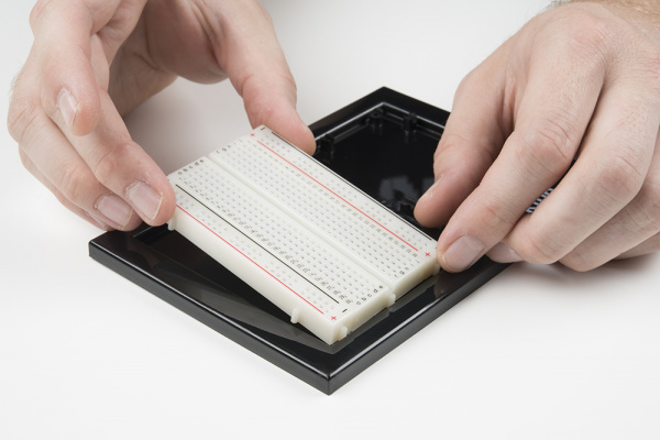
Modifying Your EL Wire Inverter

$
0
0

Modifying Your EL Wire Inverter a learn.sparkfun.com tutorial

Available online at: http://sfe.io/t920

Introduction

In this tutorial, we will modify the 12V EL wire inverter to power the EL Sequencer or EL Escudo Dos off a single power supply.

Soldering different Cable to 12V EL Inverter

Required Materials

To follow along with this tutorial, you will need the following materials at a minimum. You may not need everything though depending on what you have. Add it to your cart, read through the guide, and adjust the cart as necessary.

Tools

You will need a soldering iron, solder, and general soldering accessories. You will also need a screwdriver and multimeter for testing.

Digital Multimeter - Basic

Digital Multimeter - Basic

TOL-12966
$14.95
20
Soldering Iron - 60W (Adjustable Temperature)

Soldering Iron - 60W (Adjustable Temperature)

TOL-14456
$14.95
7
Solder Lead Free - 15-gram Tube

Solder Lead Free - 15-gram Tube

TOL-09163
$3.50
2
Pocket Screwdriver Set

Pocket Screwdriver Set

TOL-12891
$3.95
4

Suggested Reading

If you aren’t familiar with the following concepts, we recommend checking out these tutorials before continuing.

How to Solder: Through-Hole Soldering

This tutorial covers everything you need to know about through-hole soldering.

Getting Started with Electroluminescent (EL) Wire

This guide will help you get started with electroluminescent (EL) wire, tape, panel, chasing wire, and bendable wire to let your project glow!

EL Sequencer/Escudo Dos Hookup Guide

A basic guide to getting started with the SparkFun EL Sequencer and Escudo Dos to control electroluminescence (EL) wire, panels, and strips.

Hacking Your EL Wire Inverter's Input

By default, the DC input on the 12V inverter has a connector that accepts a barrel jack connector. This is usually a great feature but we'd rather have that input be a JST connector so we can hook it directly to the EL Sequencer/EL Escudo Dos off a single power supply. Don't worry, we can easily hack one in. Remove the QC sticker on the back of the 12V EL inverter. Using a Phillips screwdriver, open the inverter's enclosure.

12V Inverter and Screwdriver

Remove the screw and open the case. The PCB will look different depending on when you ordered the 12V inverter. The inverter on the left is from an older model as opposed to the one on the right. Regardless of how the PCBs look, they will still function the same.

Different 12V Inverter

Remove the board from the enclosure so that we can remove the existing wires connected to the barrel jack connector. The wires with the black sheath will be the ones that we will be desoldering. On newer 12V inverters, there should be some hot glue between the wires and PCB. This is for strain relief. If there is hot glue, carefully separate it from the cable and components on the 12V inverter. Desolder the wires connected by heating the pin or PTH pad. If necessary, give the PTH pad a small bump on the table with the slap method to remove any solder before threading new wire through it. If the diode's pin is already soldered on the PTH pad, the wire would need to be soldered to the joint. Feel free to keep the wires connected to the barrel jack in your parts bin for a different project.

Desolder Wires from the DC Input

Take note of what color wire is connected to the PTH and which side the wires were removed. The PCB may be different depending on when it was manufactured so there may not be any silkscreen indicating the input voltage for "+" and "-". The images in the center and far right did not have any silkscreen associated with the wiring. Usually the "+" is connected to the anode of the diode. In this case, we desoldered the wires from the PCB as shown in sample 3.

Inverter Sample 1Inverter Sample 2Inverter Sample 3
Sample 1Sample 2Sample 3

Having a hard time viewing the images? Click on image for a closer view.

Solder the new JST pigtail to the board. We'll be adding the wires to the bottom of the PCB. To be consistent with the wire colors for the input voltage, we will be connecting the red wire to the pad or pin that is connected to the diode's anode pin. Then we will be connecting the black wire to the other pad or pin that was desoldered.

Solder New Wires

Insert the board back into its respective enclosure while ensuring that the wires are between the openings. Re-insert the screw and tighten. Since the wire colors are the same, try labeling the EL inverter with a marker or tape to indicate the side that is the DC input and AC output. Usually the input voltage is closest to the switch.

Labeled Input and OUtput

Before powering up, insert jumper wire between your power adapter and DC input similar to how EL wire was tested in the Getting Started Guide. Since we are using the JST pigtail assembly, you will need to remove the mating connector for the JST. Add extra part to your parts bin for future projects! Keep in mind that the DC input has a polarity so VIN should be connected to the red wire and GND to black the wire. Then insert jumper wires between the AC output and EL Wire. If you need, feel free to add some electrical tape as a precaution when handling the AC output.

Jumper Wire in JST Connector For Testing

Insert the wall adapter to an outlet (or add a 9V battery if you are using this in a remote setup) to the connection to test. Using the wires connecting to the DC input, touch the red wire to the center tip of the barrel jack and the black wire to the sleeve of the wall adapter. Flip the switch if you do not see the EL powering up. The EL wire should blink or stay on depending on the mode that is used.

EL Wire Powered

Now that we have modified the EL Inverter, the next step is to use it with the EL Sequencer or EL Escudo Dos! Plug the DC input you just made into the "DC TO INVERTER" connector, plug the AC output into the "AC FROM INVERTER" connector, and we're ready to fire things up! For more information, check out the guide below to adjust the solder jumper on the board before connecting.

EL Sequencer/Escudo Dos Hookup Guide

December 3, 2015

A basic guide to getting started with the SparkFun EL Sequencer and Escudo Dos to control electroluminescence (EL) wire, panels, and strips.

Resources and Going Further

Need some inspiration for your next project? Check out some of these related tutorials:

EL Wire Light-Up Dog Harness

Learn how to create a light-up dog harness using EL wire for when you need to take your four-legged friend for a walk in the dark.

Heartbeat Straight Jacket

An EL project that displays one person's heartbeat on another person's costume.

Sound Reactive EL Wire Costume

Learn how to make your EL wire costumes sound reactive in this project tutorial.

EL Wire Hoodie

In this tutorial, we will sew standard electroluminescent (EL) wire to a hoodie.

Or try hacking the EL inverter battery pack like Bill Porter.


learn.sparkfun.com | CC BY-SA 3.0 | SparkFun Electronics | Niwot, Colorado
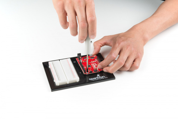
LilyPad RGB LED Hookup Guide

$
0
0

LilyPad RGB LED Hookup Guide a learn.sparkfun.com tutorial

Available online at: http://sfe.io/t835

Introduction

Heads up! This tutorial was written for the LilyPad RGB LED with common cathode. If you are using the LilyPad Tri-Color LED with common anode, please refer to the LilyPad Tri-Color LED Hookup Guide.

The LilyPad RGB LED is a specialty board that can produce a variety of colors. On the board is an RGB (red-green-blue) LED, made of three tiny LEDs connected together. Each of the colors in the RGB LED are connected to one of the sew tabs on the board labeled R, G, and B.

LilyPad RGB LED

LilyPad RGB LED

DEV-13735
$3.50

Required Materials

To follow along with the code examples, we recommend:

Suggested Reading

To add this LED to a project, you should be comfortable sewing with conductive thread and uploading code to your LilyPad Arduino (for the programming examples). Here are some tutorials to review before working with this part:

What is a Circuit?

Every electrical project starts with a circuit. Don't know what a circuit is? We're here to help.

Light

Light is a useful tool for the electrical engineer. Understanding how light relates to electronics is a fundamental skill for many projects.

Insulation Techniques for e-Textiles

Learn a few different ways to protect your conductive thread and LilyPad components in your next wearables project.

LilyPad Basics: E-Sewing

Learn how to use conductive thread with LilyPad components.

Getting Started with LilyPad

An introduction to the LilyPad ecosystem - a set of sewable electronic pieces designed to help you build soft, sewable, interactive e-textile projects.
Note on Common Anode vs Common Cathode

The color channels on this RGB LED are all connected through a common cathode (negative) pin. This configuration means that the individual red, green, and blue LEDs share a common ground tab. To light up each color individual LED, connect them each to a power source. For simple circuit hookups, this means you need to connect the R, G, or B sew tabs to power (+) and in code set them to HIGH (for digital output) or 255 (for analog output) to turn them on.

Common Anode RGB LED LilyPad Breakout Board


The RGB LED has 4 connections: red, green, blue channels, and a common cathode pin.
If you look closely you can see the individual LEDs inside the package.

Using in a Simple E-Sewing Project

The RGB LED doesn't need to be connected to a microcontroller in order to control it. Here are some examples of using simple circuits to mix colors with the LED.

To experiment with basic color mixing, you can use alligator clips on the RGB LED's sew tabs to temporarily connect them to a power source, such as a LilyPad Coin Cell Battery Holder with a coin cell battery. Connect the negative tab (-) to the negative sew tab on the battery holder with a clip, and each color tab R (Red), G (Green), and B (Blue) to the postivie tab (+) to connect them. The combination of color sew tabs that are connected to power will create a variety of colors.

LilyPad RGB LED connected to three alligator clips and a LilyPad Battery Holder

You can replace these connections with switches or buttons for a simple color mixing circuit. After prototyping and testing a project with the RGB LED, you can replace the connections with conductive thread in your project.

RGB LED stitched with conductive thread to three LilyPad Switches and a LilyPad Battery Holder

Simple color mixing circuit using a LilyPad Switches connected to each color tab of the RGB LED.

Attaching to a LilyPad Arduino

To follow along with the code examples in this tutorial, connect the RGB LED to a LilyPad Arduino as shown below. Use alligator clips to temporarily connect the R (Red) tab on the LED to 11, G (Green) to 10, B (Blue) to 9, and (-) to (-). When you are finished prototyping, replace the alligator clips with conductive thread traces for permanent installation in your project.

Note: To follow along with the Custom Color Mixing example code, you will need to attach the R, G, and B tabs to a sew tabs on the LilyPad with PWM capabilities. In this case, we are using a LilyPad Arduino USB with an ATmega32U4.

Attaching the RGB LED to a LilyPad Arduino USB

Additional Board Hookup

If you'd like to use RGB LED with the LilyPad ProtoSnap Plus, attach the R, G, and B tabs to the ProtoSnap's expansion ports. You will not be able to follow along with the Custom Color Mixing example unless you snap the ProtoSnap Plus apart and connect the RGB LED directly to tabs on the LilyPad USB Plus on pin 6, A7, and A8. Make sure to adjust the pins definitions in the example code when using the LilyPad ProtoSnap Plus.

Basic Color Mixing with Code

Note: This example assumes you are using the latest version of the Arduino IDE on your desktop. If this is your first time using Arduino, please review our tutorial on installing the Arduino IDE.

This example code demonstrates how to display a simple rainbow of colors using the RGB LED. In order to create colors with the RGB LED, you'll have to set each of the LEDs within it individually. The combination of light from the LEDs mixed together creates new colors.

Upload the following code to your LilyPad Arduino, making sure to select the correct LilyPad board from the drop down menu below. Choose LilyPad Arduino USB if using a LilyPad Arduino USB. The LilyPad Arduino Simple, LilyPad Arduino, and LilyPad Development Board, and Development Board Simple all use a LilyPad ATmega 328. Select LilyPad USB Plus if following along with the LilyPad ProtoSnap Plus.

Copy and paste the following code into the Arduino IDE and upload it to your LilyPad Arduino.

language:c
/*
  LilyPad Tri-Color LED: Basic Color Mixing
  Written by: Gella and Ho Yun "Bobby" Chan
  SparkFun Electronics
  https://www.sparkfun.com/products/13735

  Create primary and secondary colors on the tri-color (Red/Green/Blue)
  LED connected to a LilyPad Arduino.

  Tri-Color LED connections:
  R pin to 11
  G pin to 10
  B pin to 9
  - pin to -


  This code is released under the MIT License (http://opensource.org/licenses/MIT)

******************************************************************************/

// This example uses a tri-color, also known as an RGB
// (Red / Green / Blue) LED.
// This example uses digitalWrite() to turn the three LEDs on and off
// in various combinations to create eight primary and secondary colors.

//debug mode, comment one of these lines out using a syntax for a single line comment: //
#define DEBUG 0     //0 = LEDs only
//#define DEBUG 1     //1 = LEDs w/ serial output

// Create integer variables for our LED pins:
#define RGB_red 11
#define RGB_green 10
#define RGB_blue 9

void setup() {

  // Make all of our LED pins outputs:
  pinMode(RGB_red, OUTPUT);
  pinMode(RGB_green, OUTPUT);
  pinMode(RGB_blue, OUTPUT);

#if DEBUG
  Serial.begin(9600); //initialize Serial Monitor
  //while (!Serial);  // Comment out to wait for serial port to connect to Serial Monitor. Needed for native USB.
  Serial.println("Basic Color Mixing w/ a Common Cathode RGB LED");
#endif

}//end setup()

void loop() {

  // This code will step through the six primary and secondary colors, plus white and black.
  // Note: for this particular LED, the wiring shares a common anode (+), which means to
  // turn on the LEDs you will set them LOW instead of HIGH.
  // Keep this in mind as you prototype with the LED and mix your colors.

  // For each of these colors, we'll turn the necessary RGB LEDs on or off.


  // Black (all LEDs off)
  // RGB LEDs:
#if DEBUG
  Serial.println("OFF");
#endif
  digitalWrite(RGB_red, LOW);
  digitalWrite(RGB_green, LOW);
  digitalWrite(RGB_blue, LOW);
  delay(1000);

  // Red (red LED on)
#if DEBUG
  Serial.println("RED");
#endif
  digitalWrite(RGB_red, HIGH);
  digitalWrite(RGB_green, LOW);
  digitalWrite(RGB_blue, LOW);
  delay(1000);

  //Yellow (red and green LEDs on)
#if DEBUG
  Serial.println("YELLOW");
#endif
  digitalWrite(RGB_red, HIGH);
  digitalWrite(RGB_green, HIGH);
  digitalWrite(RGB_blue, LOW);
  delay(1000);

  // Green (green LED on)
#if DEBUG
  Serial.println("GREEN");
#endif
  digitalWrite(RGB_red, LOW);
  digitalWrite(RGB_green, HIGH);
  digitalWrite(RGB_blue, LOW);
  delay(1000);

  // Cyan (blue and green LEDs on)
#if DEBUG
  Serial.println("CYAN");
#endif
  digitalWrite(RGB_red, LOW);
  digitalWrite(RGB_green, HIGH);
  digitalWrite(RGB_blue, HIGH);
  delay(1000);

  // Blue (blue LED on)
#if DEBUG
  Serial.println("BLUE");
#endif
  digitalWrite(RGB_red, LOW);
  digitalWrite(RGB_green, LOW);
  digitalWrite(RGB_blue, HIGH);
  delay(1000);

  // Magenta (red and blue LEDs on)
#if DEBUG
  Serial.println("MAGENTA");
#endif
  digitalWrite(RGB_red, HIGH);
  digitalWrite(RGB_green, LOW);
  digitalWrite(RGB_blue, HIGH);
  delay(1000);

  // White (all LEDs on)
#if DEBUG
  Serial.println("WHITE");
#endif
  digitalWrite(RGB_red, HIGH);
  digitalWrite(RGB_green, HIGH);
  digitalWrite(RGB_blue, HIGH);
  delay(1000);

}//end loop

After uploading your code, the RGB LED will step through a color sequence beginning with all LEDs off ('black'), red, yellow, green, cyan, blue, magenta, and white. Once the color sequence is complete, the program will loop back to the beginning and repeat the sequence.

Turning on different combinations of three LEDs inside the RGB LED will create new colors. Combining the primary colors of light (red, green, and blue) gives different results than combining pigments in paints or inks. Turning on all three colors will create white - this is called additive color. Take a look a the graphic below to see what colors combine to create primary and secondary colors with light.

Venn Diagram for Additive Colors

Custom Color Mixing with Code

In this example, you will but use analogWrite() function to change the brightness of each channel in relation to each other. Adjusting the brightness of the red, green, and blue LEDs within the LED will allow you to create a new range of values and color combinations. You will need to confirm that the sew tabs you connect to the RGB LED have PWM capabilities - this code will run on a LilyPad Arduino USB, LilyPad Arduino Simple, LilyPad Arduino SimpleSnap, and LilyPad Main board without any changes needed.

In the last example, you created basic primary and secondary colors by turning the red, green, and blue channels on or off with different combinations. In this activity, you'll create tertiary colors by combining the three color channels at 50% brightness levels. There are actually millions of color combinations available using RGB LEDs once you begin experimenting by adjusting the brightness/saturation of each channel. This example will cover a set of twelve tertiary colors and white.

Copy and paste the following code into the Arduino IDE and upload to your LilyPad Arduino.

language:c
/*
  LilyPad RGB LED: Custom Color Mixing
  Written by: Gella and Ho Yun "Bobby" Chan
  SparkFun Electronics
  https://www.sparkfun.com/products/13735

  Expand your color options using analogWrite and the LilyPad RGB LED

  RGB LED connections:
  R pin to 11
  G pin to 10
  B pin to 9
  - pin to -

  This code is released under the MIT License (http://opensource.org/licenses/MIT)

******************************************************************************/
// In this example we'll use analogWrite to control the brightness of the three channels
// of the RGB LED.
// Here we'll create a rainbow of tertiary colors by adding a 50%-brightness option.

//debug mode, comment one of these lines out using a syntax for a single line comment: //
//#define DEBUG 0     //0 = LEDs only
#define DEBUG 1     //1 = LEDs w/ serial output

// Create integer variables for our LED pins:
#define RGB_red 11
#define RGB_green 10
#define RGB_blue 9

void setup() {

  // Make all of our LED pins outputs:
  pinMode(RGB_red, OUTPUT);
  pinMode(RGB_green, OUTPUT);
  pinMode(RGB_blue, OUTPUT);

#if DEBUG
  Serial.begin(9600); //initialize Serial Monitor
  //while (!Serial); // Comment out to wait for serial port to connect to Serial Monitor. Needed for native USB.
  Serial.println("Custom Color Mixing w/ a Common Cathode RGB LED");
#endif

}//end setup()

void loop()
{
  // In this code we'll step through twelve rainbow colors (primary, secondary, tertiary).

  // Unlike digitalWrite, which can be only HIGH (on) or LOW (off),
  // analogWrite lets you smoothly change the brightness from 0 (off) to 255 (fully on).
  // When analogWrite is used with the RGB LED, you can create millions of colors!

  // In the analogWrite() functions:
  // 0 is off
  // 128 is halfway on (used for the tertiary colors)
  // 255 is full brightness.

  // Black (all LEDs off)
  // RGB LEDs:
#if DEBUG
  Serial.println("OFF");
#endif
  analogWrite(RGB_red, 0);
  analogWrite(RGB_green, 0);
  analogWrite(RGB_blue, 0);
  delay(1000);

  // Red
#if DEBUG
  Serial.println("RED");
#endif
  analogWrite(RGB_red, 255);
  analogWrite(RGB_green, 0);
  analogWrite(RGB_blue, 0);
  delay(1000);

  // Orange
#if DEBUG
  Serial.println("ORANGE");
#endif
  analogWrite(RGB_red, 255);
  analogWrite(RGB_green, 128);
  analogWrite(RGB_blue, 0);
  delay(1000);

  // Yellow
#if DEBUG
  Serial.println("YELLOW");
#endif
  analogWrite(RGB_red, 255);
  analogWrite(RGB_green, 255);
  analogWrite(RGB_blue, 0);
  delay(1000);

  // Chartruese
#if DEBUG
  Serial.println("CHARTRUESE");
#endif
  analogWrite(RGB_red, 128);
  analogWrite(RGB_green, 255);
  analogWrite(RGB_blue, 0);
  delay(1000);

  // Green
#if DEBUG
  Serial.println("GREEN");
#endif
  analogWrite(RGB_red, 0);
  analogWrite(RGB_green, 255);
  analogWrite(RGB_blue, 0);
  delay(1000);

  // Spring Green
#if DEBUG
  Serial.println("SPRING GREEN");
#endif
  analogWrite(RGB_red, 0);
  analogWrite(RGB_green, 255);
  analogWrite(RGB_blue, 128);
  delay(1000);

  // Cyan
#if DEBUG
  Serial.println("CYAN");
#endif
  analogWrite(RGB_red, 0);
  analogWrite(RGB_green, 255);
  analogWrite(RGB_blue, 255);
  delay(1000);

  // Azure
#if DEBUG
  Serial.println("AZURE");
#endif
  analogWrite(RGB_red, 0);
  analogWrite(RGB_green, 128);
  analogWrite(RGB_blue, 255);
  delay(1000);

  // Blue
#if DEBUG
  Serial.println("BLUE");
#endif
  analogWrite(RGB_red, 0);
  analogWrite(RGB_green, 0);
  analogWrite(RGB_blue, 255);
  delay(1000);

  // Violet
#if DEBUG
  Serial.println("VIOLET");
#endif
  analogWrite(RGB_red, 128);
  analogWrite(RGB_green, 0);
  analogWrite(RGB_blue, 255);
  delay(1000);

  // Magenta
#if DEBUG
  Serial.println("MAGENTA");
#endif
  analogWrite(RGB_red, 255);
  analogWrite(RGB_green, 0);
  analogWrite(RGB_blue, 255);
  delay(1000);

  // Rose
#if DEBUG
  Serial.println("ROSE");
#endif
  analogWrite(RGB_red, 255);
  analogWrite(RGB_green, 0);
  analogWrite(RGB_blue, 128);
  delay(1000);

  // White (all LEDs on)
#if DEBUG
  Serial.println("ALL ON, WHITE");
#endif
  analogWrite(RGB_red, 255);
  analogWrite(RGB_green, 255);
  analogWrite(RGB_blue, 255);
  delay(1000);
}//end loop

After uploading your code the RGB LED will step through a rainbow sequence of red, orange, yellow, chartruese, green, spring green, cyan, azure, blue, violet, magenta, rose, and white repeatedly.

By adjusting the brightness of each LED in the RGB LED individually, we open up a much wider range of color options to display than the previous example. In fact, there are many more combinations than we show in the example code. The image below shows a chart of the tertiary colors the example program creates by stepping down the LEDs to half brightness, creating a rainbow with more color transitions than the Basic Color Mixing example. By using analog output to adjust the brightness of each color channel individually, the RGB LED can display almost any color you can choose from a color picker - if you are familiar with RGB sliders in a graphics program, you'll recognize the 0-255 values used in this code.

Tertiary Color Wheel Chart

Project Examples

Need some inspiration for your next project? Check out some of the projects below. Just make sure to adjust the connections when using the common cathode RGB LED.

Light Up Silk Flower Corsage

This tutorial uses a specialty Silk Flower LED with embedded RGB LED in it, but functions similar to the example circuit above. You can create a similar project using an RGB LED and your own flower or fabric covering.

Light Up Silk Flower Corsage

April 20, 2015

Combine a silk flower with a built-in RGB LED and some LilyPad Switches to create a customizable accessory.

Color Changing LED Brooch by Becky Stern

In this project for Craftzine, Becky uses three potentiometers to make a customizable colored LED brooch using the RGB LED.


Skirt Full of Stars by Shannon Henry

This skirt reacts to movement and displays in color with RGB LEDs and fiber optic strands. It uses a LilyPad Accelerometer connected to a LilyPad Arduino Main Board to sense movement while being worn.

Skirt Full of Stars project by Shannon Henry

Photo courtesy of PolyMath Design Lab

Resources and Going Further

Now that you've successfully got your LilyPad Tri-Color LED up and running, it's time to incorporate it into your own project! For more information about the LilyPad Tri-Color LED, check out the resources below:

Check out these other tutorials using RGB LEDs:

Hackers in Residence - Sound and Motion Reactivity for Wearables

How to consciously wear light-up and and sound reactive clothing.

Humidity-sensing LED Flower

How about that humidity? This tutorial shows how to add sensing capability to the 21st Century Fashion Kit's RGB flower project.

Light Up Silk Flower Corsage

Combine a silk flower with a built-in RGB LED and some LilyPad Switches to create a customizable accessory.

LED Cloud-Connected Cloud

Make an RGB colored cloud light! You can also control it from your phone, or hook up to the weather!

Learn more about working with LilyPad LEDs in your projects:

LilyPad Pixel Board Hookup Guide

Add changing colors to your wearable projects using LilyPad Pixel Boards.

Powering LilyPad LED Projects

Learn how to calculate how many LEDs your LilyPad project can power and how long it will last.

learn.sparkfun.com | CC BY-SA 3.0 | SparkFun Electronics | Niwot, Colorado
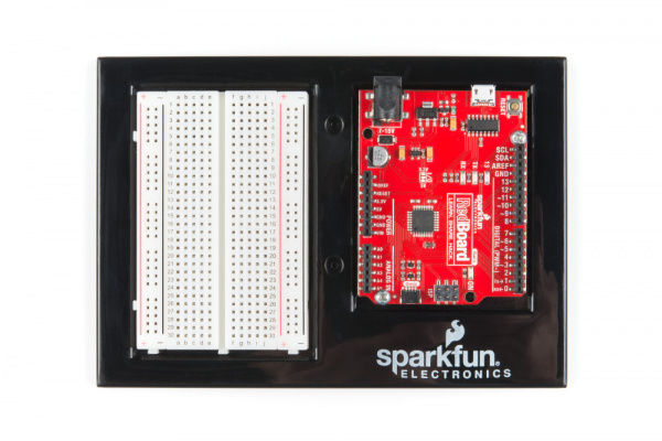
Hookup Guide for the SparkFun RedBoard Artemis

$
0
0

Hookup Guide for the SparkFun RedBoard Artemis a learn.sparkfun.com tutorial

Available online at: http://sfe.io/t925

Introduction

The SparkFun RedBoard Artemis encapsulates all the lessons we've learned through the years of improving on the original Arduino Uno while adding in the powerful Artemis module so that you can easily use the Cortex-M4F. Let's dive in!

SparkFun RedBoard Artemis

SparkFun RedBoard Artemis

DEV-15444
$19.95

Required Materials

You'll need the RedBoard Artemis and a USB C cable. Any USB C cable should work, including the one that probably came with your phone charger. If you don't have a cable you can get a 3 foot one here or a fancy reversible one here.

Reversible USB A to C Cable - 2m

Reversible USB A to C Cable - 2m

CAB-15424
$7.95
SparkFun RedBoard Artemis

SparkFun RedBoard Artemis

DEV-15444
$19.95

Suggested Reading

If you aren't familiar with the Qwiic system, we recommend reading here for an overview.

Qwiic Connect System

We also recommend checking out these tutorials before continuing:

I2C

An introduction to I2C, one of the main embedded communications protocols in use today.

RedBoard Qwiic Hookup Guide

This tutorial covers the basic functionality of the RedBoard Qwiic. This tutorial also covers how to get started blinking an LED and using the Qwiic system.

Using SparkFun Edge Board with Ambiq Apollo3 SDK

We will demonstrate how to get started with your SparkFun Edge Board by setting up the toolchain on your computer, examining an example program, and using the serial uploader tool to flash the chip.

Designing with the SparkFun Artemis

Let's chat about layout and design considerations when using the Artemis module.

Artemis Development with Arduino

Get our powerful Artemis based boards (Artemis Nano, BlackBoard Artemis, and BlackBoard Artemis ATP) blinking in less than 5 minutes using the SparkFun Artemis Arduino Core!

Hardware Overview

If you've ever used an Arduino Uno before you should be pretty familiar with the various female headers and the barrel jack power. If you're new to Arduino boards, check out the SparkFun RedBoard Qwiic tutorial for more information on many of the basic board functions you'll see on the Artemis RedBoard. In this tutorial we'll be covering the unique aspects of the RedBoard Artemis.

SparkFun RedBoard Artemis Front View

GPIO

Looking at the front of the Artemis RedBoard, you'll notice that alongside the female headers are plated through-holes. We've found that while we enjoy the ease of using the headers, sometimes we just want to solder directly to our board. To that end, we've added the PTH rails. Note that these are NOT all ground pins - these pins have whatever functionality is labeled beside their female header companions.

Pin Rails on the Front of the Artemis RedBoard

Serial and JTAG Programming

The RedBoard Artemis has two methods for programming. The most common is the USB C connector that operates as a USB to serial bridge. By simply pressing 'Upload' in the Arduino IDE or 'make bootload' from the SDK the firmware on Artemis is updated.

RedBoard Artemis USB C and JTAG ports

USB-C and JTAG footprints

We use the CH340C on the RedBoard Artemis. The driver should automatically install on most operating systems. However, there is a wide range of operating systems out there. You may need to install drivers the first time you connect the chip to your computer's USB port or when there are operating system updates. For more information, check out our How to Install CH340 Drivers Tutorial.

New!

How to Install CH340 Drivers

August 6, 2019

How to install CH340 drivers (if you need them) on Windows, Mac OS X, and Linux.

The second method is JTAG programming. An unpopulated JTAG footprint is available for more advanced users who need breakpoint level debugging. We recommend checking out our JTAG section for the compatible male header and a compatible JTAG programmer and debugger.

Mic and RTC

The Artemis exceeds at low power voice recognition. To enable this we've included a PDM MEMS microphone on the board. Additionally, the Artemis module can operate an RTC given an external 32kHz crystal so we've included that was well.

PDM Microphone and RTC on RedBoard Artemis

Qwiic and I2C

The I2C pins on the Artemis are labeled SDA and SCL. They are controlled in the Arduino IDE using Wire.begin(), Wire.read(), etc. The same SDA/SCL pins are connected to the Qwiic connector so you can use SparkFun's Qwiic ecosystem (there's over 50 boards and more every week!).

Qwiic connector on RedBoard Artemis

Serial0, AREF, and USB Pads

On the rear of the RedBoard are some advanced features. Normally, an AREF pin is located between the SDA and GND pins. The Artemis module has no equivalent pin so we've converted that pin to GND. If you have a shield that utilizes the AREF pin or just want to free it, you can cut the AREF jumper and the labeled 'GND' located between SDA and GND will be left disconnected.

On Artemis, TX0/RX0 are used for bootloading new code and Serial.println() statements to the computer's terminal window. The CH340C takes care of the serial to USB conversion. However, if you need access to these pins, they're available. TX0/RX0 can be used as GPIO as well as special functions, but for most applications these pins are left as Serial for bootloading.

For users who are embedding the RedBoard Artemis into an enclosure the USB pads are exposed so that an external USB connector can be located at the edge of the enclosure and wired back to the USB pads.

Rear of RedBoard Artemis showing various SMD pads and jumpers

Busmaster Pads

One amazing aspect of the Artemis is the large number of SPI and I2C buses available. We at SparkFun decided that it would be better to have more PWM and ADC pins routed to the female headers on the front of the board, rather than extra I2C and SPI pins. But we just couldn't resist! We've made Wire1/SPI1 and Wire3/SPI3 available to users through the SMD pads on the bottom of the board. These pins can be used as GPIO if needed and pins 28/29 are PWM enabled as well.

Bus master pads on rear of RedBoard Artemis

Current Measurement Jumper

The Artemis can run as low as 6μA/MHz meaning the module can run at 48MHz at less than half a milliamp. To enable measurements and to isolate the power hungry devices (such as the LM317 voltage regulator) we've added a NC (normally closed) jumper. By cutting the jumper the VDD trace to the module is interrupted. Soldering in a male jumper or wires into the accompanying holes will give you the ability to insert a current meter and precisely monitor how much current your application is consuming.

Current Measurement Jumper

For the vast majority of projects a wall adapter or USB power can be used. But when properly isolated the Artemis can run on a coincell battery for weeks! So we've designed in a 20mm SMD coin cell footprint so that users can experiment with powering the Artemis from a standard CR2032. You can pickup the compatible coincell holder here.

Coin Cell Location

Bypass Jumper

USB C is wonderful. It's reversible and can source up to 2 amps at 5 volts without any power delivery (PD) negotiation. We've included a 2A resettable fuse (often called a PTC) on the Artemis as a safety feature in case your project decides to consume inordinate amounts of power (And possibly begins to spark and set fire. That was fun wasn't it? Get it? SparkFun?). In the event the RedBoard begins to pull more than 2 amps from the USB source, the resettable fuse will automatically trigger and disconnect the board from the computer or power supply. This should protect your power source and the traces on your RedBoard.

However, there are plenty of legitimate projects that need more than 2A. We've designed the power traces to withstand up to 2A with a 10C rise in temperature. If your power supply can provide adequate power, and you know what you are doing, you can close the BYP jumper circumventing the resettable fuse.

The bypass jumper on RedBoard Artemis

Software Setup

The BlackBoard Artemis runs both Arduino and the more advanced Ambiq HAL/SDK. Checkout these tutorials to get you up and blinking in 5 minutes!

Artemis Development with Arduino

June 20, 2019

Get our powerful Artemis based boards (Artemis Nano, BlackBoard Artemis, and BlackBoard Artemis ATP) blinking in less than 5 minutes using the SparkFun Artemis Arduino Core!

Using SparkFun Edge Board with Ambiq Apollo3 SDK

March 28, 2019

We will demonstrate how to get started with your SparkFun Edge Board by setting up the toolchain on your computer, examining an example program, and using the serial uploader tool to flash the chip.

Troubleshooting

Resources and Going Further

Did you know you can use the RedBoard Artemis as the starting point of your very own Artemis product? Get the design files from our repo here and edit them using Eagle PCB!

For more information on the RedBoard Artemis and the Artemis module itself, check out the links below:

You've now explored the board, let's get blinking with Arduino! Or perhaps you want to learn a little more about the Artemis module itself. Checkout these tutorials!

Designing with the SparkFun Artemis

Let's chat about layout and design considerations when using the Artemis module.

Artemis Development with Arduino

Get our powerful Artemis based boards (Artemis Nano, BlackBoard Artemis, and BlackBoard Artemis ATP) blinking in less than 5 minutes using the SparkFun Artemis Arduino Core!

Hookup Guide for the BlackBoard Artemis Nano

Get started with the powerful BlackBoard Artemis Nano

Did you know the Artemis is compatible with our Qwiic line? Checkout these products that simply plug in and work!

SparkFun GPS Breakout - XA1110 (Qwiic)

SparkFun GPS Breakout - XA1110 (Qwiic)

GPS-14414
$49.95
4
SparkFun Grid-EYE Infrared Array Breakout - AMG8833 (Qwiic)

SparkFun Grid-EYE Infrared Array Breakout - AMG8833 (Qwiic)

SEN-14607
$40.95
SparkFun LTE CAT M1/NB-IoT Shield - SARA-R4 (with Hologram SIM Card)

SparkFun LTE CAT M1/NB-IoT Shield - SARA-R4 (with Hologram SIM Card)

CEL-15087
$84.95
1
SparkFun Qwiic MP3 Trigger

SparkFun Qwiic MP3 Trigger

DEV-15165
$19.95
3

learn.sparkfun.com | CC BY-SA 3.0 | SparkFun Electronics | Niwot, Colorado
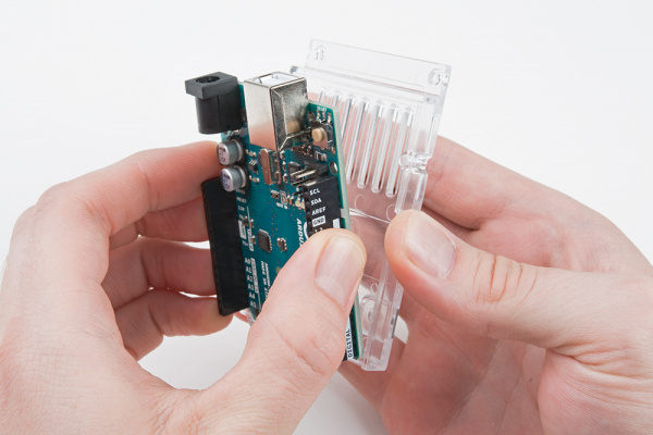
Hookup Guide for the SparkFun RedBoard Artemis ATP

$
0
0

Hookup Guide for the SparkFun RedBoard Artemis ATP a learn.sparkfun.com tutorial

Available online at: http://sfe.io/t927

Introduction

We affectionately refer to the RedBoard Artemis ATP as the "All The Pins!" board, since it breaks out every single one of the Artemis Module's 48 GPIO pins into a familiar Mega-like form factor. On top of the RedBoard's improved power conditioning and USB to serial, we've added a slew of features to help you take full advantage of the Artemis module's unique features. Let's have a look!!

SparkFun RedBoard Artemis ATP

SparkFun RedBoard Artemis ATP

DEV-15442
$24.95

Required Materials

You'll need the RedBoard Artemis ATP and a USB C cable. Any USB C cable should work, including the one that probably came with your phone charger.

USB 2.0 Cable A to C - 3 Foot

USB 2.0 Cable A to C - 3 Foot

CAB-15092
$3.95
SparkFun RedBoard Artemis ATP

SparkFun RedBoard Artemis ATP

DEV-15442
$24.95

Suggested Reading

If you aren't familiar with the Qwiic system, we recommend reading here for an overview.

Qwiic Connect System

We also recommend checking out these tutorials before continuing:

I2C

An introduction to I2C, one of the main embedded communications protocols in use today.

RedBoard Qwiic Hookup Guide

This tutorial covers the basic functionality of the RedBoard Qwiic. This tutorial also covers how to get started blinking an LED and using the Qwiic system.

Using SparkFun Edge Board with Ambiq Apollo3 SDK

We will demonstrate how to get started with your SparkFun Edge Board by setting up the toolchain on your computer, examining an example program, and using the serial uploader tool to flash the chip.

Designing with the SparkFun Artemis

Let's chat about layout and design considerations when using the Artemis module.

Artemis Development with Arduino

Get our powerful Artemis based boards (Artemis Nano, BlackBoard Artemis, and BlackBoard Artemis ATP) blinking in less than 5 minutes using the SparkFun Artemis Arduino Core!

Hardware Overview

If you've ever used an Arduino Mega before you should be pretty familiar with the various female headers and the barrel jack power. In this tutorial we'll be covering the unique aspects of the RedBoard Artemis ATP.

Front view of the SparkFun RedBoard Artemis ATP

GPIO

Remember our "All the Pins!" nickname? Well, we meant it. On the RedBoard Artemis ATP, not only have we broken out all the major pins with female headers, we've added a secondary rail of plated through-holes alongside them to give you the choice of either plug and play or soldering directly to the board.

Pin rails on the front of the RedBoard Artemis ATP

On the side of the board, instead of doubling the pin availability, we've added a rail of ground pins for ease of use.

Ground pins highlighted next to pins 3, 36, 38, 37, and 44

Click on the image for a closer look

Serial and JTAG Programming

The RedBoard Artemis ATP has two methods for programming. The most common is the USB C connector that operates as a USB to serial bridge. By simply pressing 'Upload' in the Arduino IDE or 'make bootload' from the SDK the firmware on Artemis is updated.

We use the CH340C on the RedBoard Artemis ATP. The driver should automatically install on most operating systems. However, there is a wide range of operating systems out there. You may need to install drivers the first time you connect the chip to your computer's USB port or when there are operating system updates. For more information, check out our How to Install CH340 Drivers Tutorial.

New!

How to Install CH340 Drivers

August 6, 2019

How to install CH340 drivers (if you need them) on Windows, Mac OS X, and Linux.

The second method is JTAG programming. We've populated the JTAG footprint for more advanced users who need breakpoint level debugging. We recommend checking out our JTAG section for the compatible JTAG programmer and debugger.

RedBoard Artemis ATP USB C and JTAG ports

USB-C and JTAG footprints

Mic and RTC

The Artemis exceeds at low power voice recognition. To enable this we've included a PDM MEMS microphone on the board. Additionally, the Artemis module can operate an RTC given an external 32kHz crystal so we've included that was well.

PDM Microphone and RTC on RedBoard Artemis ATP

Pins 36 and 37 are connected to the onboard PDM MEMS microphone and are broken out on the upper right side of the ATP board. You can hookup a second PDM microphone to pins 36/37 or you can load PDM firmware onto the Artemis module and watch PDM traffic from the microphone(s). Notice the ground pins next to pins 36 and 37!

Pins 36 and 37 are on the upper right hand side of the front of the board

Click on the image for a closer look

If you have no plans to use the on-board microphones, pins 36 and 37 can be used as GPIO by cutting the jumpers on the back of the board.

Cut these two jumpers on the back of the board to use Pins 36 and 37 as GPIO

Qwiic and I2C

The I2C pins on the Artemis are labeled SDA and SCL. They are controlled in the Arduino IDE using Wire.begin(), Wire.read(), etc. The same SDA/SCL pins are connected to the Qwiic connector so you can use SparkFun's Qwiic ecosystem (there's over 50 boards and more every week!).

Qwiic connector on RedBoard Artemis ATP and I2C Ports

Serial0, AREF, and USB Pads

On the rear of the RedBoard ATP are some advanced features. Normally, an AREF pin is located between to the SDA and GND pins. The Artemis module has no equivalent pin so we've converted that pin to GND. If you have a shield that utilizes the AREF pin or just want to free it, you can cut the AREF jumper and the labeled 'GND' located between SDA and GND will be left disconnected.

On Artemis, TX0/RX0 are used for bootloading new code and Serial.println() statements to the computer's terminal window. The CH340C takes care of the serial to USB conversion. However, if you need access to these pins, they are available. TX0/RX0 can be used as GPIO as well as special functions, but for most applications these pins are left as Serial for bootloading.

For users who are embedding the RedBoard Artemis ATP into an enclosure, the USB pads are exposed so that an external USB connector can be located at the edge of the enclosure and wired back to the USB pads.

Back of RedBoard Artemis ATP showing various SMD pads and jumpers

Current Measurement Jumper

The Artemis can run as low as 6μA/MHz, meaning the module can run at 48MHz at less than half a milliamp. To enable measurements and to isolate the power hungry devices (such as the LM317 voltage regulator) we've added a NC (normally closed) jumper. By cutting the jumper the VDD trace to the module is interrupted. Soldering in a male jumper or wires into the accompanying holes will give you the ability to insert a current meter and precisely monitor how much current your application is consuming.

For the vast majority of projects a wall adapter or USB power can be used. But when properly isolated the Artemis can run on a coincell battery for weeks! So we've designed in a 20mm SMD coin cell footprint so that users can experiment with powering the Artemis from a standard CR2032. You can pickup the compatible coincell holder here.Be careful when soldering, the coincell silk screen pads are a bit larger than usual.

Current Measurement Jumper

Click the image for a closer look

Coin Cell Battery Pads

Click the image for a closer look

Bypass Jumper

USB C is wonderful. It's reversible and can source up to 2 amps at 5 volts without any power delivery (PD) negotiation. We've included a 2A resettable fuse (often called a PTC) on the Artemis as a safety feature in case your project decides to consume inordinate amounts of power (And possibly begins to spark and set fire. That was fun wasn't it? Get it? SparkFun?). In the event the RedBoard begins to pull more than 2 amps from the USB source, the resettable fuse will automatically trigger and disconnect the board from the computer or power supply. This should protect your power source and the traces on your RedBoard.

However, there are plenty of legitimate projects that need more than 2A. We've designed the power traces to withstand up to 2A with a 10C rise in temperature. If your power supply can provide adequate power, and you know what you are doing, you can close the BYP jumper, thus circumventing the resettable fuse.

The bypass jumper on RedBoard Artemis ATP

I/O Masters

You can have up to 6 I2C or SPI masters with the RedBoard Artemis ATP, and these pins are distributed across the board. Be sure to check out the good examples built into the Artemis Arduino core showing how to easily enable additional ports.

Example I2C sketches built into Artemis core

In addition we've listed each of the masters below with their associated pins. Check out the Apollo3 PinMap for more information.

MasterSCK/SCLMISO/SDAMOSI
M0567
M18910
M2272528
M3424338
M4394044
M5484947

Software Setup

The RedBoard Artemis ATP runs both Arduino and the more advanced Ambiq HAL/SDK. Checkout these tutorials to get you up and blinking in 5 minutes!

Artemis Development with Arduino

June 20, 2019

Get our powerful Artemis based boards (Artemis Nano, BlackBoard Artemis, and BlackBoard Artemis ATP) blinking in less than 5 minutes using the SparkFun Artemis Arduino Core!

Using SparkFun Edge Board with Ambiq Apollo3 SDK

March 28, 2019

We will demonstrate how to get started with your SparkFun Edge Board by setting up the toolchain on your computer, examining an example program, and using the serial uploader tool to flash the chip.

Troubleshooting

Resources and Going Further

Did you know you can use the RedBoard Artemis ATP as the starting point of your very own Artemis product? Get the design files from our repo here and edit them using Eagle PCB!

For more information on the RedBoard Artemis and the Artemis module itself, check out the links below:

You've now explored the board, let's get blinking with Arduino! Or perhaps you want to learn a little more about the Artemis module itself. Checkout these tutorials!

Designing with the SparkFun Artemis

Let's chat about layout and design considerations when using the Artemis module.

Artemis Development with Arduino

Get our powerful Artemis based boards (Artemis Nano, BlackBoard Artemis, and BlackBoard Artemis ATP) blinking in less than 5 minutes using the SparkFun Artemis Arduino Core!
New!

Hookup Guide for the SparkFun RedBoard Artemis Nano

Get started with the powerful RedBoard Artemis Nano

Did you know the Artemis is compatible with our Qwiic line? Checkout these products that simply plug in and work!

Qwiic Cable - Breadboard Jumper (4-pin)

Qwiic Cable - Breadboard Jumper (4-pin)

PRT-14425
$1.50
SparkFun RedBoard Qwiic

SparkFun RedBoard Qwiic

DEV-15123
$19.95
3
Zio Current and Voltage Sensor - INA219 (Qwiic)

Zio Current and Voltage Sensor - INA219 (Qwiic)

SEN-15176
$7.95
1
SparkFun Atmospheric Sensor Breakout - BME280 (Qwiic)

SparkFun Atmospheric Sensor Breakout - BME280 (Qwiic)

SEN-15440
$14.95

learn.sparkfun.com | CC BY-SA 3.0 | SparkFun Electronics | Niwot, Colorado
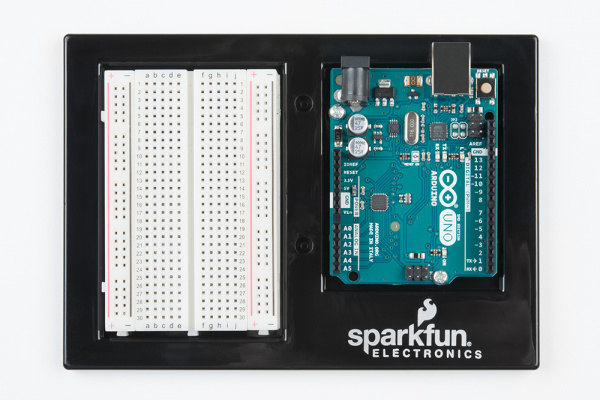

Hookup Guide for the SparkFun RedBoard Artemis Nano

$
0
0

Hookup Guide for the SparkFun RedBoard Artemis Nano a learn.sparkfun.com tutorial

Available online at: http://sfe.io/t926

Introduction

We like to joke that the SparkFun RedBoard Artemis Nano is a party on the front and all business on the rear! A light weight, 0.8mm thick PCB, with on board lipo-battery charging and a Qwiic connector, this board is easy to implement into very small projects. A dual row of ground connections make it easy to add lots of buttons, LEDs, and anything that requires its own GND connection. At the same time, the board is breadboard compatible if you solder the inner rows of pins. Add into that all the bells and whistles of the Artemis module and you've got one heck of a party going on. Let's check it out!

SparkFun RedBoard Artemis Nano

SparkFun RedBoard Artemis Nano

DEV-15443
$14.95

Required Materials

You'll need a USB C cable for programming. Any USB C cable should work including the one that probably came with your phone charger. If you don't already have a USB C cable you can pick one up here or you can get a fancy reversible one.

Reversible USB A to C Cable - 2m

Reversible USB A to C Cable - 2m

CAB-15424
$7.95
SparkFun RedBoard Artemis Nano

SparkFun RedBoard Artemis Nano

DEV-15443
$14.95

Suggested Reading

Qwiic Connect System

We also recommend checking out these tutorials before continuing:

I2C

An introduction to I2C, one of the main embedded communications protocols in use today.

Using SparkFun Edge Board with Ambiq Apollo3 SDK

We will demonstrate how to get started with your SparkFun Edge Board by setting up the toolchain on your computer, examining an example program, and using the serial uploader tool to flash the chip.

Designing with the SparkFun Artemis

Let's chat about layout and design considerations when using the Artemis module.

Artemis Development with Arduino

Get our powerful Artemis based boards (Artemis Nano, BlackBoard Artemis, and BlackBoard Artemis ATP) blinking in less than 5 minutes using the SparkFun Artemis Arduino Core!

Hardware Overview

Power, GPIOs and GND Connections

The Nano breaks out 17 GPIO to PTH holes. Each GPIO is paired with a ground connection. We found the extra grounds immeasurably useful when wiring up projects; you'll often need a separate ground for each LED, button, or sensor. The Nano makes it that much easier to prototype an idea.

Pin Rails on the front and back of the Artemis Nano

Power is automatically selected between USB, LiPo, and Vin (Vin takes precedence). The VIN pin can handle up to 6V and will be regulated down to 3.3V using the AP2112 voltage regulator (600mA max output). The 3.3V pin can be used to power various 3.3V devices up to 600mA.

USB C and Serial Bootloading

We've designed the Nano with a reversible USB C connector and the CH340E USB to serial IC. This is an amazing IC that is small enough to fit under the USB C connector.

SparkFun Artemis Nano with USB highlighted

The driver should automatically install on most operating systems. However, there is a wide range of operating systems out there. You may need to install drivers the first time you connect the chip to your computer's USB port or when there are operating system updates. For more information, check out our How to Install CH340 Drivers Tutorial.

New!

How to Install CH340 Drivers

August 6, 2019

How to install CH340 drivers (if you need them) on Windows, Mac OS X, and Linux.

The current USB C configuration is with two 5.1k Ohm resistors. This will allow up to 2 amps at 5 volts from your USB source. Nearly all modern computers and battery packs have short circuit protection but just be aware that the Nano does not have any short circuit protection.

Reset and Power Control

The Nano is a great device to embed in a project. But if it's embedded, it is often impossible to access the reset and power switches on a board. We've exposed the reset pin and a Power Switch pin. This is a perfect place to solder a big external power switch. The PSWC pin controls the enable line on the 3.3V regulator. Pull this line low and the board will turn off. Release the PSWC line and the board will run normally. The enable line is pulled high with a resistor so if you don't hookup anything the board will operate normally.

SparkFun Artemis reset and power switch

RTC and PDM Microphone

The Artemis has built in RTC capabilities if it is given a 32kHz source so we've added a 32kHz crystal to the Nano. Additionally, one of the main applications of the Artemis is voice recognition so we've added a MEMS digital PDM microphone to the board so that you can capture and analyze audio.

SparkFun Artemis Nano mic and RTC

LiPo Battery and Charging

The Nano has integrated LiPo power and charging. Any one of our LiPo batteries with work great with the Nano. The CHG LED will illuminate while the battery is charging via USB and will turn off when the battery is at peak voltage. Charge rate is set to 500mA. The general rule of thumb is charge no faster than 1C so the minimum recommended battery size is a 500mAh battery, but any of the larger batteries will work just fine.

LiPo Battery and Charging highlighted

Software Setup

The RedBoard Artemis Nano runs both Arduino and the more advanced Ambiq HAL/SDK. Checkout these tutorials to get you up and blinking in 5 minutes!

Artemis Development with Arduino

June 20, 2019

Get our powerful Artemis based boards (Artemis Nano, BlackBoard Artemis, and BlackBoard Artemis ATP) blinking in less than 5 minutes using the SparkFun Artemis Arduino Core!

Using SparkFun Edge Board with Ambiq Apollo3 SDK

March 28, 2019

We will demonstrate how to get started with your SparkFun Edge Board by setting up the toolchain on your computer, examining an example program, and using the serial uploader tool to flash the chip.

Troubleshooting

My Nano is not showing up as a COM port?!

Most Artemis carrier boards use the CH340C IC which is not affected by this issue. This issue is only for the Nano that uses the much smaller CH340E.

CH340E showing up as weird USB serial device

We've had some issues with the CH340E having an incorrect Vendor ID. If your PC is showing the above as an unknown USB2.0-Serial device you may have this issue.

CH340E showing VID of 0x9986

Device showing Vendor ID of 0x9986 when it should be 0x1A86

For the Nano we needed to use the much smaller CH340E that has only RTS. The CH340E and RTS work fine to reset the Artemis module and activate the SparkFun variable bootloader with one exception: according to the company when the RTS pin has too much load resistance the IC will enumerate incorrectly with VID 0x9986 (correct VID is 0x1A86). It's a very weird failure mode that is not documented. We'll be working closely with the CH340 manufacturer WCH to get this resolved on future Nano boards.

There are two solutions if you experience this:

Option 1: Unplugging and re-plugging USB will cause the IC to properly enumerate under the correct VID/PID and the drivers will work as expected. This works well if you remember to do it but if you're like me, I'll forget two weeks from now and wonder why the COM port isn't coming up.

Option 2: Force Windows to use the correct drivers. WCH (the company behind the CH340) has good drivers but the INF for Windows is expecting the PID of 0x1A86. Here are the steps to make the drivers work even with a VID of 0x9986:

Unknown serial device in windows manager

Step 1: Step 5: Be sure to download and install the Windows driver from the WCH website.

Step 2: Open device manager and locate the problem serial device.

Update CH340 device driver

Step 3: Right click on the device and update driver

Select from available list of drivers

Step 4: Select the driver from the available list of drivers

Select ports

Step 5: Navigate to the Ports.

Select wch.cn from the mfg list

Step 6: Scroll to the bottom of the manufacturer's list and select wch.cn. Select CH340 in the right hand window. If you do not see wch.cn on the list then download and install the Windows driver from the WCH website and repeat the above steps.

Tell windows you are sure

Step 7: Tell Windows you are sure.

COM port is correctly listed

Step 8: Verify the COM port is appearing correctly.

Once you have the driver installed for both VIDs you computer will correctly enumerate a COM port regardless of how cranky the CH340E is feeling that day.

As mentioned above, we'll get this sorted out with WCH soon.

Need more help?

Resources and Going Further

Did you know you can use the RedBoard Artemis Nano as the starting point of your very own Artemis product? Get the design files from our repo here and edit them using Eagle PCB!

You've now explored the board, let's get blinking with Arduino! Or perhaps you want to learn a little more about the Artemis module itself. Checkout these tutorials!

Designing with the SparkFun Artemis

Let's chat about layout and design considerations when using the Artemis module.

Artemis Development with Arduino

Get our powerful Artemis based boards (Artemis Nano, BlackBoard Artemis, and BlackBoard Artemis ATP) blinking in less than 5 minutes using the SparkFun Artemis Arduino Core!

Did you know the Artemis is compatible with our Qwiic line? Checkout these products that simply plug in and work!

SparkFun Triple Axis Magnetometer Breakout - MLX90393 (Qwiic)

SparkFun Triple Axis Magnetometer Breakout - MLX90393 (Qwiic)

SEN-14571
$14.95
SparkFun Thing Plus - ESP32 WROOM

SparkFun Thing Plus - ESP32 WROOM

WRL-14689
$20.95
5
SparkFun RedBoard Qwiic

SparkFun RedBoard Qwiic

DEV-15123
$19.95
3
Qwiic Button - Blue

Qwiic Button - Blue

SPX-15585
$3.95

learn.sparkfun.com | CC BY-SA 3.0 | SparkFun Electronics | Niwot, Colorado
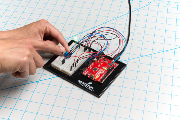
SparkFun gator:RTC Hookup Guide

$
0
0

SparkFun gator:RTC Hookup Guide a learn.sparkfun.com tutorial

Available online at: http://sfe.io/t923

Introduction

Most of you probably have done a science experiment that required data of some sort of to be recorded. In which case, the data often had a temporal component that also needed to be recorded...

SparkFun gator:RTC - micro:bit Accessory Board

SparkFun gator:RTC - micro:bit Accessory Board

COM-15486
$14.95

The gator:RTC is a real-time clock. This means that the gator:RTC can be used as a supplemental data logging tool, in conjunction with the gator:log to add precise timing to your data collection. Therefore, student(s) can put down that stopwatch and start focusing more attention on what is happening in their experiments. Other applications for the gator:RTC include time lapse photography, timers and alarms, clocks, and etc.

This tutorial will show you how to get started using this gator:RTC with the gator:bit (v2) in the micro:bit development environment.

Required Materials

To get started, you'll need a micro:bit to control everything. Each of the products below includes a micro:bit, but the kit and bundle also include some additional accessories that you may want as well.

SparkFun Inventor's Kit for micro:bit

SparkFun Inventor's Kit for micro:bit

KIT-15228
$49.95
1
micro:bit Go Bundle

micro:bit Go Bundle

DEV-14336
$16.50
16
micro:bit Board

micro:bit Board

DEV-14208
$14.95
7

To easily use the gator board ecosystem, a gator:bit (v2) will help breakout the necessary pins and you will also need alligator and/or banana cables to connect the gator:bit to the gator:RTC.

SparkFun gator:bit v2.0 - micro:bit Carrier Board

SparkFun gator:bit v2.0 - micro:bit Carrier Board

DEV-15162
$19.95
Alligator Test Leads - Multicolored (10 Pack)

Alligator Test Leads - Multicolored (10 Pack)

PRT-12978
$3.25
4
Banana to Banana Cable - Right Angle

Banana to Banana Cable - Right Angle

CAB-15368
$4.95

(*These banana cables have a special diameter on the attachment points designed specifically for use with the micro:bit ecosystem. They may or may not be compatible with the banana cables used on your test equipment.)

You may already have some of these materials, so feel free to modify your cart as necessary.

Suggested Reading

The gator:RTC sensor is pretty straight forward to use in application. However, you may find the following concepts useful along the way.

Logic Levels

Learn the difference between 3.3V and 5V devices and logic levels.

I2C

An introduction to I2C, one of the main embedded communications protocols in use today.

Qwiic Real Time Clock Module (RV-1805) Hookup Guide

Find out what time it is, even after the power's been out on your project for a while with the Qwiic Real Time Clock (RTC) module.
New!

SparkFun gator:log Hookup Guide

The gator:log is a serial communication based data logger. This tutorial will get you started using the gator:log with the micro:bit platform.

If you aren't familiar with the micro:bit, we recommend reading here for an overview.

We would also recommend taking a look at the following tutorials if you aren't familiar with them.

Getting Started with the micro:bit

The BBC micro:bit is a compact, powerful programming tool that requires no software installation. Read on to learn how to use it YOUR way!

How to Load MicroPython on a Microcontroller Board

This tutorial will show you how to load the MicroPython interpreter onto a variety of development boards.

SparkFun gator:bit v2 Hookup Guide

The gator:bit v2 is a breakout board for the BBC micro:bit. The gator:bit exposes almost every pin on the micro:bit to clippable pad with circuit protection. It also has as built-in addressable LEDs and a built-in buzzer.

Hardware Overview

The gator:RTC consists of 4 pads for power and data.

ContactsDirectionDescription
GNDN/AGround: Reference voltage and ground loop.
3.3VInPower: Provides 3.3V to board.
SDABi-directionalData: Data and commands are transmitted between the RV-3028 and microcontroller.
SCLInClock: The microcontroller provides the timing needed to communicate on the data line.

Power

The specified operating voltage for the RV-3028 is between 1.2 - 5V. For use with the gator:bit (v2) and micro:bit, you should provide 3.3V through the 3V3 and GND pads to keep the logic levels consistent.

Power Connections
Power connection pads.

Backup Battery

The board also includes a 1mAh lithium-metal rechargeable, coin type backup battery. This allows the RTC module to keep track of time even when power to the board is cut (for low power applications). Although, current consumption varies by how the RTC is operating and the temperature, users should expect a fully charged backup battery to last for several months with the RTC operating conservatively.

Backup Battery
Backup battery.

Here are some of the characteristics of the battery from the datasheet:

CharacteristicRange
Nominal Voltage3.0V
Nominal Capacity1.0mAh (3.1V - 2.0V)
Discharge Current5µA

RV-3028

The RV-3028 is an extremely low power real-time clock (RTC), consuming only 40 - 60nA on average at 3V, which interfaces over an I2C bus. A real-time clock is used to keep track of the current time, which is a useful, but often forgotten tool. For the most part, users will only need to know I2C addresses of this board to prevent address conflicts with other devices or sensors.

RV-3028 IC
RV-3028: Real-Time Clock.

Here are some of the characteristics of the RV-3028 RTC, for details, check out the datasheet and application manual:

CharacteristicRange
Operating Voltage1.2V to 5V
Supply Current (@3V)40nA to 60nA (avg.) (~330nA peak)
5µA to 40µA (active I2C-bus)
95nA to 150nA (backup battery operation)
Operating Temperature-40°C to 85°C
Xtal (Internal Oscillator) Frequency 32.768 kHz (&PlusMinus; 5ppm @ 25°)
Timing AccuracyFactory calibrated: &PlusMinus; 1ppm @ 25°C (no temp. compensation)
Calender RangeAutomatic leap year correction: 2000 to 2099
CounterSeconds, minutes, hours, date, month, year and weekday
I2C Address 7-bit Slave Address: X1010010b, where X is the R/W bit
0x52 - Write Address
0xD2 - Read Address
Note: The I2C address indicated on the datasheet is incorrect. The R/W bit is the MSB and not the LSB, as shown in the table above.

What is Time?

Time is the continuous progression of events which succeed one another from the past and into the future. By most human standards, time is measured in a base unit of time, called a second. Most recently, the second (SI unit of time) was re-defined to a more specific standard:

It is defined by taking the fixed numerical value of the cesium frequency ΔνCs, the unperturbed ground-state hyperfine transition frequency of the cesium-133 atom, to be 9,192,631,770 when expressed in the unit Hz, which is equal to s-1.

Below, are additional resources regarding the topic of time:

What is an RTC?

RTC stands for real-time clock, which is used to keep track of time. With the convenience of modern electronics such as computers, smartphones, GPS navigation, and IoT/smart devices, the importance of an RTC can be easily overlooked. An RTC is different from an oscillator or hardware clock that only generates a clock signal; the primary difference being that an RTC can keep track of the time. In the case of the gator:log, the RV-3028 is is able to keep track of time by the month, day (including weekday), year (leap-year accurate from 2000 to 2099), hours (12-hour format), minutes, and seconds. This is useful for a variety of applications including, but not limited to data logging, timers, and other long duration projects like time-lapse photography.

The key benefits of using an RTC in your project is that they are:

  • Low Power: The RV-3028 only consumes about 40 - 60nA when only tracking time.
  • No Power: With the backup battery, the RV-3028 is able to keep track of time. The clock stored on a micro:bit would resume from the last point of reference or reset depending on the methods used.
  • Accuracy: The RV-3028 is factory calibrated to &PlusMinus; 1ppm. This equates to a deviation of less than 32 seconds over the course of the year. (*Your average wrist watch is accurate to about &PlusMinus; 50ppm, which is a variance of 27 minutes per year.)

The drawbacks of an RTC that should be considered before using it in your project are:

  • Resolution: The resolution of the RV-3028 is limited to 1 second intervals.
  • Latency: Although the RTC operates on a "higher" speed I2C bus, cycles are still spent accessing timing data from the module. In addition to the limited resolution, this limits the functionality of an RTC for high speed applications, like a data acquisition systems.

The RTC is most useful for long duration projects. Here is a list of some examples:

Time Stamp Button

In addition to tracking time, the gator:RTC also includes a time stamp button to mark events. When pressed, the RV-3028 stores a time stamp of the button press. Therefore, it queried consistently, this button can be used to mark significant events in a data log. For example, marking the end point of a pH titration in a data set.

Time stamp button
Time stamp button.
Note: Only a single time stamp is stored by the RV-3028. Therefore, it is advisable to query the RTC often enough so that previous time stamps aren't overwritten before they can be collected.

I2C Connection

I2C is a communication protocol used to transfer data between master and slave devices. It is a 2-wire connection consisting of SDA (data) and SCL (clock). The protocol is pretty well defined so it can be shared with multiple devices. This is beneficial for daisy chaining multiple devices together on a single bus. The primary thing users will need to watch out for is address conflicts (you can't have devices with the same address).

I2C Connection
I2C connection pads.

Hardware Assembly

Connecting your gator:RTC to the gator:bit (v2) is simple. The board can also be daisy-chained with other I2C boards. This can easily be done with alligator cables or these special banana cables.

Hardware Assembly
Hardware assembly of connections used in example. Click to enlarge.
Daisy Chain
Example of daisy chaining multiple I2C gator boards. Click to enlarge.
Gator:RTCGND3V3SDASCL
Gator:BitGND3.3V OUTP20 (SDA)P19 (SCL)

Adding the MakeCode Extension

Note: This tutorial assumes you are familiar with MakeCode, the gato:bit (v2), and the micro:bit board.

The easiest way to get started using the gator:RTC is to use Microsoft MakeCode, a web-based block editor. This tutorial assumes you are familiar with the with MakeCode, the gato:bit (v2), and the micro:bit development board. If this is your first time check out this guides linked in the suggested reading section (above).

Installing Extensions

To get started with using MakeCode with the miccro:bit, head over to the MakeCode for micro:bit website by Microsoft. Then, click the New Project button to start a new project and open the Editor. (*Yes, all you only need to get start coding is a computer with internet access, an up-to-date web browser, and an available USB port!)

MakeCode Website
Click the New Project button to start a new project and open the Editor. Click on image to enlarge.

Once you have the editor up, click on the the Advanced block in the block library to reveal the drop down menu.

Editor
Click on the the Advanced block in the block library to reveal the drop down menu. Click on image to enlarge.

Finally, click on the Extensions block. This should bring up the extensions page. (*Alternatively, you could also click on the extensions link from the settings menu.)

Advanced Block
Click on the the Extensions block to open the extensions page. Click on image to enlarge.

There are two methods for finding the gator:RTC extension:

  • Search for the name used on the extension3.
  • Use the link to the GitHub repository for the pxt-package as the search term.

Extensions Page
Use the search bar to find the extension you want to install. Click on image to enlarge.
Note: Unfortunately, it does take time to get an extension approved by the micro:bit Educational Foundation before it can be searchable by name. Part of the requirements for the approval process involves a live product page. Therefore, at the time of the launch of this product, the extension has not been approved yet and the only method of adding the extension is to use the link to the GitHub repository of the pxt-package. We will update this tutorial as soon as the extension has been approved.

Search for the PXT-Package

Search for the gator:RTC extension using the GitHub repository link to the pxt-package:

https://github.com/sparkfun/pxt-gator-RTC

Search for Extension
Search for Extension. Then, click on the box to add it to the block library. Click on image to enlarge.

Then, click on the box for the extension to add it to the block library. The gator:RTC extension should now appear in the block library.

Extension in Block Library
Extension in the block library; click on the block to open menu options. Click on image to enlarge.

To verify that you have added the extension, click on the gator:RTC block to make sure that your drop down menu options match the image below.

Menu Options
Available blocks for the gator:RTC extension. Click on image to enlarge.

MakeCode Examples

Now that you have added the gator:particle extension to the Editor, lets start with some example code. Plug the micro:bit into your computer using an USB micro-B cable after you have assembled your hardware with the instructions from the previous section. The micro:bit should appear on your computer as a removable storage device.

USB Drive
The micro:bit showing up as a USB drive on a Windows computer. Click to enlarge.

To upload new code, this is where you will be copying the downloaded .hex file to later.

Block Functions

set time to ___
: ___
: ___
- _____
This block should allows users to set the time stored in the RTC. The time should take the following format: HH:MM:SS in a 12-hour format. This block doesn't prohibit invalid entries (e.g 13:01:53 AM). Double check the time that is being set is valid; otherwise, the RTC may respond improperly when called upon.
  • HH- Integer value for the our in 12-hour format (i.e. The 3rd hour after 12 should be entered as 3). There is also a slider that can be easily used.
    • 0 to 12
  • MM- Minutes in integer format (i.e. The 20th minute past the hour should be entered as 20). There is also a slider that can be easily used.
    • 0 to 59
  • SS- Seconds in integer format (i.e. The 30th second past the minute should be entered as 20). There is also a slider that can be easily used.
    • 0 to 59
  • 12-Hour Period- Drop down menu to select the 12-hour period.
    • AM- Ante meridiem (i.e. before noon).
    • PM- Post meridiem (i.e. after noon).

set date to _____
, _____
- ___
- 20___
This block should allows users to set the date stored in the RTC. The date should take the following format: Weekday, Month - DD - 20YY. This block doesn't prohibit invalid entries (e.g Feb 29th for leap years, Sept. 31st, or YY = 100). Double check the date that is being set is valid; otherwise, the RTC may respond improperly when called upon.
  • Weekday- Drop down menu to select the weekday.
    • Monday
    • Tuesday
    • Wednesday
    • Thursday
    • Friday
    • Saturday
    • Sunday
  • Month- Drop down menu to select the month.
    • January
    • February
    • March
    • April
    • May
    • June
    • July
    • August
    • September
    • October
    • November
    • December
  • DD- Day in integer format (i.e. The 3rd should be entered as 3). There is also a slider that can be easily used.
    • 0 to 31
  • YY- Year in integer format (i.e. The 2019 should be entered as 19). (The calender is only leap-year accurate for the years 2000 to 2099.)
    • 0 to 99

set _____ to ___
This block should allows users to change a specific component of time. This block doesn't prohibit invalid entries. Double check the that the modification is valid; otherwise, the RTC may respond improperly when called upon.

  • Unit of Time- Drop down menu to select the unit of time you want to change.
    • Seconds
    • Minutes
    • Hours
    • Date
    • Month
    • Year
    • Weekday
  • Value- Value in integer format.
    • Seconds- Input an integer:
      • 0 to 59
    • Minutes- Input an integer:
      • 0 to 59
    • Hours- Input an integer:
      • 0 to 12 (if in 12-hour format)
      • 0 to 24 (if in 24-hour format)
    • Date- Input an integer:
      • 0 to 31
    • Month- Input an integer:
      • 0 to 12
    • Year- Input an integer:
      • 0 to 99
    • Weekday- Input an integer:
      • 0- Monday
      • 1- Tuesday
      • 2- Wednesday
      • 3- Thursday
      • 4- Friday
      • 5- Saturday
      • 6- Sunday

value of _____
This is a value block that returns the value for the stored component of time from the RTC.

  • Unit of Time- Drop down menu to select the unit of time you want to retrieve.
    • Seconds- Returns an integer:
      • 0 to 59
    • Minutes- Returns an integer:
      • 0 to 59
    • Hours- Returns an integer:
      • 0 to 12 (if in 12-hour format)
      • 0 to 24 (if in 24-hour format)
    • Date- Returns an integer:
      • 0 to 31
    • Month- Returns an integer:
      • 0 to 12
    • Year- Returns an integer:
      • 0 to 99
    • Weekday- Returns an integer:
      • 0- Monday
      • 1- Tuesday
      • 2- Wednesday
      • 3- Thursday
      • 4- Friday
      • 5- Saturday
      • 6- Sunday

text of weekday
This is a value block that returns a string for the weekday.

time in HH:MM:SS
This is a value block that returns a string for the time stored by the RTC in a HH:MM:SS format.

date in mm-dd-yyyy
This is a value block that returns a string for the date stored by the RTC in a mm-dd-yyyy format.

button timestamp in HH:MM:SS
This is a value block that returns a string for the previous time, marked by the RTC timestamp button in a HH:MM:SS format.

button timestamp in mm-dd-yyyy
This is a value block that returns a string for the previous date, marked by the RTC timestamp button in a mm-dd-yyyy format.

set time to ___:___:___ in 24 hour mode
This block allows users to set the time stored in the RTC. The time should take the following format: HH:MM:SS in a 24-hour format. This block doesn't prohibit invalid entries (e.g 25:01:53). Double check the time that is being set is valid; otherwise, the RTC may respond improperly when called upon.

  • HH- Integer value for the our in 24-hour format (i.e. The 3rd hour after midnight should be entered as 3). There is also a slider that can be easily used.
    • 0 to 24
  • MM- Minutes in integer format (i.e. The 20th minute past the hour should be entered as 20). There is also a slider that can be easily used.
    • 0 to 59
  • SS- Seconds in integer format (i.e. The 30th second past the minute should be entered as 20). There is also a slider that can be easily used.
    • 0 to 59

time in yyyy-mm-ddThh:mm:ss
This is a value block returns a string for the time stored by the RTC in ISO8601 format.

date in dd-mm-yyyy
This is a value block that returns a string for the date stored in the RTC in dd-mm-yyyy format.

button timestamp in yyyy-mm-ddThh:mm:ss
This is a value block returns a string for the previous time, marked by the RTC timestamp button in ISO8601 format.

button timestamp in dd-mm-yyyy
This is a value block returns a string for the previous time, marked by the RTC timestamp button in dd-mm-yyyy format.

value of button timestamp in _____
This is a value block that returns a specific component of timestamp stored by the RTC.

  • Unit of Time- Drop down menu to select the unit of time you want to retrieve from timestamp.
    • Seconds- Returns an integer:
      • 0 to 59
    • Minutes- Returns an integer:
      • 0 to 59
    • Hours- Returns an integer:
      • 0 to 24 (in 24-hour format)
    • Date- Returns an integer:
      • 0 to 31
    • Month- Returns an integer:
      • 0 to 12
    • Year- Returns an integer:
      • 0 to 99

set to _____ time
This block allows users to change the time format between a 12-hour and 24-hour.

  • Standard- Changes the time to a 12-hour format.
  • Military- Changes the time to a 24-hour format.

Basic Setup and Time Retrieval

Below, is a simple example of how to take simple readings from the RTC. To use this example, there are multiple options for accessing the .hex file:

  • Replicate the block functions from the display below to copy the example project. Then download the .hex file.
  • Expand the display widow to pull up the example project. Then download the .hex file.
  • Use this link to pull up the example project. Then download the .hex file.
  • Download the .hex file from the button below or the link on the bottom of the display.

The output is redirected over the serial port to avoid conflicts on pins P0 and P1, which are also used for serial communication. To read the sensor values, pull up your favorite serial terminal emulator. Then, connect to the serial port that the micro:bit is on; the default baud rate is 115200 bps. Below, is an example of an output of the time stored by the gator:RTC using the example code.

Sample Readings
Example of readings from the RTC.

In the read out from the RTC, you can see with the 1.5 and 0.8 second delays that the resolution of the RTC is limited to one second intervals. (Between the change from a 1.5 to a 0.8 delay, the seconds value was reset back to 0 seconds.) Additionally, you should note the various subtleties in timing formats for the functions used.

Pressing Timestamp Button
Pressing timestamp button to change RTC output.

If you are confused to how the timestamp button works, the read out in the forever loop prints out both the current time and the timestamp of the last button press. In the example readings, you can see the timestamp change from a few button presses.

Troubleshooting

Power and Connections

Check that your power and data connections are correct and that the power VOUT switch is in the ON position on the gator:bit (v2).

Resolution

The RTC only reports the time down to 1 second intervals and cannot return fractions of a second. It will report the lower value between seconds until the next second is hit (e.g. at 15.6 seconds past the minute is will report 15 seconds until the the 16th second is reached).

If you still have questions or issues with this product, please create a post on our forum under the Gator Products topic.

Additionally, if you are an educator and you have class or application based questions, please create a post on our forum under the Educational Products topic.

Resources and Going Further

For more product information, check out the resources below:

Interested in the micro:bit? Check out some of these other micro:bit products:

SparkFun micro:climate kit for micro:bit

SparkFun micro:climate kit for micro:bit

KIT-15301
$117.95
1
SparkFun gator:bit v2.0 - micro:bit Carrier Board

SparkFun gator:bit v2.0 - micro:bit Carrier Board

DEV-15162
$19.95
SparkFun Inventor's Kit for micro:bit Lab Pack

SparkFun Inventor's Kit for micro:bit Lab Pack

LAB-15229
$450.00
SparkFun Inventor's Kit for micro:bit

SparkFun Inventor's Kit for micro:bit

KIT-15228
$49.95
1

Need some inspiration for your next project? Check out some of these other micro:bit product tutorials:

micro:arcade Kit Experiment Guide

We love games! We love writing games, building games and yes, even building game consoles. So we want to introduce to you the micro:arcade kit for the micro:bit!

micro:bit Breakout Board Hookup Guide

How to get started with the micro:bit breakout board.

SparkFun gator:bit v2 Hookup Guide

The gator:bit v2 is a breakout board for the BBC micro:bit. The gator:bit exposes almost every pin on the micro:bit to clippable pad with circuit protection. It also has as built-in addressable LEDs and a built-in buzzer.
New!

SparkFun gator:UV Hookup Guide

The gator:UV is an I2C UV sensor. This tutorial will get you started using the gator:UV with the micro:bit platform.

learn.sparkfun.com | CC BY-SA 3.0 | SparkFun Electronics | Niwot, Colorado
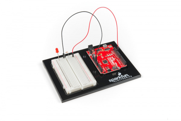
SparkFun gator:UV Hookup Guide

$
0
0

SparkFun gator:UV Hookup Guide a learn.sparkfun.com tutorial

Available online at: http://sfe.io/t897

Introduction

Do you have a science experiment involving weather or UV light exposure?

SparkFun gator:UV - micro:bit Accessory Board

SparkFun gator:UV - micro:bit Accessory Board

SEN-15273
$6.95

The gator:UV is the perfect tool to monitor the UV exposure in your next experiment. With the VEML6070, the gator:UV can easily be used to measure the levels of UVA (320-400 nm) radiation. This tutorial will show you how to get started using this UV sensor with the gator:bit (v2) in the micro:bit development environment.

Required Materials

To get started, you'll need a micro:bit to control everything. You can purchase one individually on in a kit.

SparkFun Inventor's Kit for micro:bit

SparkFun Inventor's Kit for micro:bit

KIT-15228
$49.95
1
micro:bit Go Bundle

micro:bit Go Bundle

DEV-14336
$16.50
16
micro:bit Board

micro:bit Board

DEV-14208
$14.95
7

To easily use the gator board ecosystem, a gator:bit (v2) will help breakout the necessary pins and you will also need alligator and/or banana cables to connect the gator:bit to the gator:UV.

SparkFun gator:bit v2.0 - micro:bit Carrier Board

SparkFun gator:bit v2.0 - micro:bit Carrier Board

DEV-15162
$19.95
Alligator Test Leads - Multicolored (10 Pack)

Alligator Test Leads - Multicolored (10 Pack)

PRT-12978
$3.25
4
Banana to Banana Cable - Right Angle

Banana to Banana Cable - Right Angle

CAB-15368
$4.95

(*These banana cables have a special diameter on the attachment points designed specifically for use with the micro:bit ecosystem. They may or may not be compatible with the banana cables used on your test equipment.)

You may already have some of these materials, so feel free to modify your cart as necessary.

Suggested Reading

The gator:UV sensor is pretty straight forward to use in application. However, you may find the following concepts useful along the way.

Light

Light is a useful tool for the electrical engineer. Understanding how light relates to electronics is a fundamental skill for many projects.

Logic Levels

Learn the difference between 3.3V and 5V devices and logic levels.

I2C

An introduction to I2C, one of the main embedded communications protocols in use today.

micro:climate Kit Experiment Guide

A weather station kit that is built on top of the inexpensive, easy-to-use micro:bit and Microsoft MakeCode.

If you aren't familiar with the micro:bit, we recommend reading here for an overview.

We would also recommend taking a look at the following tutorials if you aren't familiar with them.

Getting Started with the micro:bit

The BBC micro:bit is a compact, powerful programming tool that requires no software installation. Read on to learn how to use it YOUR way!

How to Load MicroPython on a Microcontroller Board

This tutorial will show you how to load the MicroPython interpreter onto a variety of development boards.

SparkFun gator:bit v2 Hookup Guide

The gator:bit v2 is a breakout board for the BBC micro:bit. The gator:bit exposes almost every pin on the micro:bit to clippable pad with circuit protection. It also has as built-in addressable LEDs and a built-in buzzer.

Hardware Overview

The gator:UV consists of 4 pads for power and data.

ContactsDirectionDescription
GNDN/AGround: Reference voltage and ground loop.
3.3VInPower: Provides 3.3V to sensor.
SDABi-directionalData: Data and commands are transmitted between the sensor and microcontroller.
SCLInClock: The microcontroller provides the timing needed to communicate on the data line.

Power

The specified operating voltage for the VEML6070 is between 2.7V - 5.5V. For use with the gator:bit (v2) and micro:bit, you should provide 3.3V through the 3V3 and GND pads to keep the logic levels consistent.

Power Connections and LED
Power connection pads and power indication LED.

VEML6070

The VEML6070 is a UV sensor that communicates over an I2C bus. The VEML6070 detects UVA radiation up to 328 mW/cm2 with a resolution of 5 µW/cm2. For the most part, users will only need to know I2C addresses to prevent address conflicts with other devices or sensors.

VEML6070 IC
VEML6070 UV sensor.

Here are some of the characteristics of the VEML6070 sensor from the datasheet:

CharacteristicRange
Operating Voltage2.7V to 5.5V
Supply Current240 µA
UVA Detectionup to 328 mW/cm2
UVA Resolution5 µW/cm2/step
I2C Address 0x70 - Write Commands
0x73 - Read MSB of UV Data
0x71 - Read LSB of UV Data

performance chracteristics
Performance characteristics from the datasheet. Click to enlarge.

What is UVA Radiation?

UVA radiation is a specific part of the spectrum of the solar radiation from the Sun. UVA light has wavelengths between 320 nm and 400 nm. Approximately, 4.9% of all solar radiation that makes it to the surface of the Earth is UVA light. UVA rays are often associated with photoaging and the formation of skin cancer.

solar radiation penetration through atmosphere
Penetration of solar radiation through Earth's atmosphere (from VEML6070 App. Note). Click to enlarge.

For more details on UV radiation, check out these online resources:

Some experiments and related topics for UVA radiation:

I2C Connection

I2C is a communication protocol used to transfer data between master and slave devices. It is a 2-wire connection consisting of SDA (data) and SCL (clock). The protocol is pretty well defined so it can be shared with multiple devices. This is beneficial for daisy chaining multiple devices together on a single bus. The primary thing users will need to watch out for is address conflicts (you can't have devices with the same address).

I2C Connection
I2C connection pads.

Hardware Assembly

Connecting your gator:UV to the to the gator:bit (v2) is simple. The board can also be daisy-chained with other I2C boards. This can easily be done with alligator cables or these special banana cables.

Hardware Assembly
Hardware assembly of connections used in example. Click to enlarge.
Daisy Chain
Example of daisy chaining multiple I2C gator boards. Click to enlarge.
gator:UVGND3V3SDASCL
gator:bit (v2)GND3.3V OUTP20 (SDA)P19 (SCL)

Adding the MakeCode Extension

Note: This tutorial assumes you are familiar with MakeCode, the gato:bit (v2), and the micro:bit board.

The easiest way to get started using the gator:UV is to use Microsoft MakeCode, a web-based block editor. This tutorial assumes you are familiar with the with MakeCode, the gato:bit (v2), and the micro:bit development board. If this is your first time check out this guides linked in the suggested reading section (above).

Installing Extensions

To get started with using MakeCode with the miccro:bit, head over to the MakeCode for micro:bit website by Microsoft. Then, click the New Project button to start a new project and open the Editor. (*Yes, all you only need to get start coding is a computer with internet access, an up-to-date web browser, and an available USB port!)

MakeCode Website
Click the New Project button to start a new project and open the Editor. Click on image to enlarge.

Once you have the editor up, click on the the Advanced block in the block library to reveal the drop down menu.

Editor
Click on the the Advanced block in the block library to reveal the drop down menu. Click on image to enlarge.

Finally, click on the Extensions block. This should bring up the extensions page. (*Alternatively, you could also click on the extensions link from the settings menu.)

Advanced Block
Click on the the Extensions block to open the extensions page. Click on image to enlarge.

There are two methods for finding the gator:UV extension:

  • Search for the name used on the extension1.
  • Use the link to the GitHub repository for the pxt-package as the search term.

Extensions Page
Use the search bar to find the extension you want to install. Click on image to enlarge.
Note: Unfortunately, it does take time to get an extension approved by the micro:bit Educational Foundation before it can be searchable by name. Part of the requirements for the approval process involves a live product page. Therefore, at the time of the launch of this product, the extension has not been approved yet and the only method of adding the extension is to use the link to the GitHub repository of the pxt-package. We will update this tutorial as soon as the extension has been approved.

Search for the PXT-Package

Search for the gator:UV extension using the GitHub repository link to the pxt-package:

https://github.com/sparkfun/pxt-gator-UV

Search for Extension
Search for Extension. Then, click on the box to add it to the block library. Click on image to enlarge.

Then, click on the box for the extension to add it to the block library. The gator:UV extension should now appear in the block library.

Extension in Block Library
Extension in the block library; click on the block to open menu options. Click on image to enlarge.

To verify that you have added the extension, click on the gator:UV block to make sure that your drop down menu options match the image below.

Menu Options
Available blocks for the gator:UV extension. Click on image to enlarge.

MakeCode Examples

Now that you have added the gator:particle extension to the Editor, lets start with some example code. Plug the micro:bit into your computer using an USB micro-B cable after you have assembled your hardware with the instructions from the previous section. The micro:bit should appear on your computer as a removable storage device.

USB Drive
The micro:bit showing up as a USB drive on a Windows computer. Click to enlarge.

To upload new code, this is where you will be copying the downloaded .hex file to later.

Block Functions

Initialize gator:UV sensor
This block should be pretty self explanatory, it sets the sensor up to be used. You should use this within the on start block.

get UVA Reading
This is a value block as indicated by the block's shape. The output of the block is value measured by the UV sensor.

  • 0 to 65535- A 16-bit value of the UV sensor reading that can be correlated to the UV-Index.

set refresh time on UV Sensor to _____
This sets the integration time for the UV sensor. The refresh time should be adjusted for the range of values you expect to be measuring.

  • half- Half of the normal integration time.
  • one- Normal integration time (default).
  • two- Twice the normal integration time.
  • four-Four times the normal integration time.

Note:*Although not exactly correct, it can be interpreted as the time that the sensor spends collecting a data sample.

If you are barely measuring changes between measurement values, you should try to increase the refresh time, which allows the sensor to collect more light. The relation between measured values and the reset time are linear (see table below).

UV Index

The table below maps out UV index to the correlating sensor output values and their respective refresh time (or integration time) setting. The values were extrapolated from the UV index tables provided in the VEML6070 Application Note for an RSET = 300k&ohm;.

Int. Time = x0.5Int. Time = x1Int. Time = x2Int. Time = x4UVI (Value)UV-INDEX
&GreaterEqual; 1142&GreaterEqual; 2283&GreaterEqual; 4565&GreaterEqual; 9130&GreaterEqual; 11Extreme
831 to 11411661 to 22823321 to 44646641 to 91298 to 10Very High
623 to 8301246 to 16602491 to 33204981 to 66406,7High
312 to 622623 to 12451245 to 24902490 to49803 to 5Moderate
0 to 3110 to 6220 to 12440 to 24890 to 2Low

Basic Reading

Below, is a simple example of how to take simple measurements from the sensor. To use this example, there are multiple options for accessing the .hex file:

  • Replicate the block functions from the display below to copy the example project. Then download the .hex file.
  • Expand the display widow to pull up the example project. Then download the .hex file.
  • Use this link to pull up the example project. Then download the .hex file.
  • Download the .hex file from the button below or the link on the bottom of the display.

The output is redirected over the serial port to avoid conflicts on pins P0 and P1, which are also used for serial communication. To read the sensor values, pull up your favorite serial terminal emulator. Then, connect to the serial port that the micro:bit is on; the default baud rate is 115200 bps. Below, is an example of the sensor output for the example code (the sensor values are responding to the flashlight on my phone).

Sample Readings
Example of readings from the sensor.

Do Not Try This at Home: In case you were thinking about it, do NOT try to replicate this image or attempt to max out your readings with a magnifying glass. You will burn or damaged the board. I had the magnifying glass focused on the board for less than a second for this picture and it started to burn and smolder.

Magnifying Glass

Troubleshooting Tips

Power and Connections

Check that your power and data connections are correct and that the power VOUT switch is in the ON position on the gator:bit (v2).

UV Filters

Make sure that if you are using a transparent cover over the sensor that it still passes UV light. More modern clear plastics and glass covers (especially for photo or documents) usually have a special UV coating to prevent pigment deterioration and yellowing of paper.

If you still have questions or issues with this product, please create a post on our forum under the Gator Products topic.

Additionally, if you are an educator and you have class or application based questions, please create a post on our forum under the Educational Products topic.

Resources and Going Further

For more product information, check out the resources below:

Interested in the micro:bit? Check out some of these other micro:bit products:

SparkFun micro:climate kit for micro:bit

SparkFun micro:climate kit for micro:bit

KIT-15301
$117.95
1
SparkFun gator:bit v2.0 - micro:bit Carrier Board

SparkFun gator:bit v2.0 - micro:bit Carrier Board

DEV-15162
$19.95
SparkFun Inventor's Kit for micro:bit Lab Pack

SparkFun Inventor's Kit for micro:bit Lab Pack

LAB-15229
$450.00
SparkFun Inventor's Kit for micro:bit

SparkFun Inventor's Kit for micro:bit

KIT-15228
$49.95
1

Need some inspiration for your next project? Check out some of these other micro:bit product tutorials:

micro:bit Breakout Board Hookup Guide

How to get started with the micro:bit breakout board.

SparkFun gator:bit v2 Hookup Guide

The gator:bit v2 is a breakout board for the BBC micro:bit. The gator:bit exposes almost every pin on the micro:bit to clippable pad with circuit protection. It also has as built-in addressable LEDs and a built-in buzzer.

SparkFun gator:particle Hookup Guide

The gator:particle is an I2C heart-rate monitor and pulse oximeter that can be used as a particle sensor. This tutorial will get you started using the gator:particle with the micro:bit platform.

SparkFun gator:environment Hookup Guide

The gator:environment combines two I2C sensors for temperature, humidity, pressure, eCO2, and eTVOC values. This tutorial will get you started using the gator:environment with the micro:bit platform.

learn.sparkfun.com | CC BY-SA 3.0 | SparkFun Electronics | Niwot, Colorado

SparkFun gator:log Hookup Guide

$
0
0

SparkFun gator:log Hookup Guide a learn.sparkfun.com tutorial

Available online at: http://sfe.io/t924

Introduction

Note: The gator:log will NOT function properly when used with the original gator:bit. Users should use the updated gator:bit (v2) with the gator:log for it to operate properly.

Most of you probably have done a science experiment that required data of some sort to be recorded...

SparkFun gator:log - micro:bit Accessory Board

SparkFun gator:log - micro:bit Accessory Board

DEV-15270
$12.95

The gator:log is the perfect data logging tool for your next experiment. With the automation of the data collection process, gone are the days of rushing around with a pen and composition notebook to simultaneously record data and your observations. Now, you only need to sit back and observe your experiment (or just wait for it to complete, if no observations are necessary).

The gator:log allows a student(s) to focus more on the experiment than watching a thermometer or sensor readout. Additionally, the micro:bit can still be used to provide a graphical display for observing changes in data, when a sensor readout is required. If tied in conjunction with the gator:RTC, stop watches on time based experiments can become a thing of the past too (with the added benefit of more accurate timing results)!

This tutorial will show you how to get started using this gator:log with the gator:bit (v2) in the micro:bit development environment.

Required Materials

Note: The gator:log will NOT function properly when used with the original gator:bit. Users should use the updated gator:bit (v2) with the gator:log for it to operate properly.

To get started, you'll need a micro:bit to control everything. Each of the products below includes a micro:bit, but the kit and bundle also include some additional accessories that you may want as well.

SparkFun Inventor's Kit for micro:bit

SparkFun Inventor's Kit for micro:bit

KIT-15228
$49.95
1
micro:bit Go Bundle

micro:bit Go Bundle

DEV-14336
$16.50
16
micro:bit Board

micro:bit Board

DEV-14208
$14.95
7

To easily use the gator board ecosystem, a gator:bit (v2) will help breakout the necessary pins and you will also need alligator and/or banana cables to connect the gator:bit to the gator:log.

SparkFun gator:bit v2.0 - micro:bit Carrier Board

SparkFun gator:bit v2.0 - micro:bit Carrier Board

DEV-15162
$19.95
Alligator Test Leads - Multicolored (10 Pack)

Alligator Test Leads - Multicolored (10 Pack)

PRT-12978
$3.25
4
Banana to Banana Cable - Right Angle

Banana to Banana Cable - Right Angle

CAB-15368
$4.95

(*These banana cables have a special diameter on the attachment points designed specifically for use with the micro:bit ecosystem. They may or may not be compatible with the banana cables used on your test equipment.)

Additionally, users will also need a µSD card and a µSD USB reader:

microSD Card with Adapter - 16GB (Class 10)

microSD Card with Adapter - 16GB (Class 10)

COM-13833
5
microSD Card with Adapter - 32GB (Class 10)

microSD Card with Adapter - 32GB (Class 10)

COM-14832
$24.95
microSD USB Reader

microSD USB Reader

COM-13004
$4.95
8
microSD Card - 1GB (Class 4)

microSD Card - 1GB (Class 4)

COM-15107
$4.95

You may already have some of these materials, so feel free to modify your cart as necessary.

Suggested Reading

The gator:log is pretty straight forward to use in application. However, you may find the following concepts useful along the way.

Serial Communication

Asynchronous serial communication concepts: packets, signal levels, baud rates, UARTs and more!

Serial Terminal Basics

This tutorial will show you how to communicate with your serial devices using a variety of terminal emulator applications.

OpenLog Hookup Guide

An introduction to working with the OpenLog data logger.
New!

SparkFun gator:RTC Hookup Guide

The gator:RTC is an I2C based, real-time clock (RTC) for keeping time while your micro:bit isn't powered. This tutorial will get you started using the gator:RTC with the micro:bit platform.

If you aren't familiar with the micro:bit, we recommend reading here for an overview.

We would also recommend taking a look at the following tutorials if you aren't familiar with them.

Getting Started with the micro:bit

The BBC micro:bit is a compact, powerful programming tool that requires no software installation. Read on to learn how to use it YOUR way!

How to Load MicroPython on a Microcontroller Board

This tutorial will show you how to load the MicroPython interpreter onto a variety of development boards.

SparkFun gator:bit v2 Hookup Guide

The gator:bit v2 is a breakout board for the BBC micro:bit. The gator:bit exposes almost every pin on the micro:bit to clippable pad with circuit protection. It also has as built-in addressable LEDs and a built-in buzzer.

Hardware Overview

The gator:log consists of 5 pads for power, data, and an interrupt.

ContactsDirectionDescription
GNDN/AGround: Reference voltage and ground loop.
3.3VInPower: Provides 3.3V to the board.
RXInData and commands are transmitted to the gator:log from an external microcontroller (i.e. micro:bit).
TXOutData can be read from an SD card on the gator:log by an external microcontroller (i.e. micro:bit).
RSTInPin goes high or low based on if the gator:log needs to be initialized.

Power

The specified operating voltage for the ATmega328 is between 1.8V - 5.5V. For use with the gator:bit (v2) and micro:bit, you should provide 3.3V through the 3V3 and GND pads to keep the logic levels consistent.

Power Connections
Power connection pads.

ATmega328P

The heart of the gator:log is an ATmega328P microcontroller. The ATmega328P is used to handle the incoming data and store it on an µSD card. It is also used to handle all the file directory, organization functions available for the gator:log. For the most part, users just need to be aware that the RST pad must be connected in addition to the other pads.

ATmega328P
ATmega328P microcontroller.

Here are some of the characteristics of the ATmega328P microcontroller from the datasheet:

CharacteristicRange
Operating Voltage1.8V to 5.5V
Current Idle: approx. 25 mA (avg.)
Peak: approx. 35mA (w/ status LEDs flashing)
StorageSD Card
Input Channels1- Serial Data
Speed Input: Serial Data
Output: Serial Data

Reset Pad

The reset pad is used to initialize the begin function for the ATmega328P microcontroller. This pin must be connected when the gator:log is initialized to function properly.

Reset Pad
Reset pad.

What is a Data Logger?

A data logger is a device that records data over time, usually from an instrument or sensor. Most often, they are low power, use a microprocessor, include (internal or external) data storage options, contained in a compact enclosure, and are battery powered. Generally, data loggers are useful for collecting data from remote locations for extended periods of time. In s, these devices will include a renewable power source for self sufficiency and may have a remote data link when it is not be feasible to constantly drive out to change batteries and/or data storage.

Below is a list of a few examples of data logging applications:

  • Weather Stations and Buoys
  • Monitoring Agricultural Conditions
  • Road Traffic
  • Wildlife Conservation
  • Building Monitors (i.e. for Power/Water usage and HVAC Efficiency)
  • Monitoring for Athletes Performance (Biosenors)

For more details on data logging applications, check out these online resources:

µSD Card Slot

A µSD (micro SD) card slot is available to for a µSD card, which is needed to store the data sent to the gator:log. The gator:log uses the SPI pins of the ATmega328P to send data to the SD card from a temporary buffer. In most cases, users only need to consider the recording time of the gator:log, know that the µSD card requires proper formatting, and be aware of the restrictions on the SD cards that are compatible with the gator:log, which are laid out in the table below.

SD Card Slot
Spring loaded µSD card slot.
CharacteristicRange
StyleµSD card (microSD)
Type SD (SDSC)
SDHC
Class&GreaterEqual;4
Capacity64MB to 32GB
FormatFAT16 or FAT32

Although, many users may already have a few SD cards lying around, the characteristics laid out in the table are known to be compatible with the gator:log. Be aware that using SD cards that fall outside of these restrictions are not guaranteed to work. If you aren't sure about the style or type of SD card you have, please check out this Wikipedia article on SD cards for more details.

Spring-Loaded Locking Mechanism: Once the SD card is placed in the slot, push in the card once. You should hear a soft click when the card is locked into place. To unlock or release the card, push the card in again. You should hear another click when it unlocks and the card will pop out. The card should slide out easily; if you feel resistance pulling out the card, it is probably still locked in place. Do NOT try to pry or force the SD card out of the slot, this will damage the locking mechanism and render the gator:log useless.


Locking Mechanism

Calculating Data Usage

For most users, we recommend checking out our 1GB SD card. In most cases, this should hold enough data for a few sensors (depending on the amount of data you are storing and how quickly you are sampling that data).

Example Case:
  • Our 1GB SD card has about 970MB of storage capacity
  • Recording from 10 sensors
  • Each sensor sends 20 characters of data
  • Sampling rate of 1 ms

or

At 4850 seconds, that gives you about 1.3 hours of recording time. Now 1 ms is a pretty high data sampling rate, if you reduce that to 10 ms (or 100 times per second) and your recording time increases to about 13.5 hours.

If users need a longer recording time, they can change to an SD card with a higher storage capacity, change how often data is recorded, decrease the number of sensors used, or reduce the amount of characters stored per data set.

Status Indicator LEDs

There are two status LEDs on the gator:log to help with troubleshooting.

Status LEDs
Status LEDs: ST1 is blue and ST2 is green.

ST1 (Blue)

This blue indicator LED is attached to pad 5 of the ATmega328P. Mostly, users only need to be aware that this LED blinks when serial communication is functioning (i.e. data is being sent from the micro:bit to the gator:log).

ST2 (Green)

This green LED is connected to the SPI clock line on the ATmega328P. Mostly, users only need to be aware that this LED only blinks when the when the gator:log is recording data to the µSD card.

Note: If you are only sending short bursts of data, the green ST2 LED will be a lot more dim compared to the blue ST1 LED. You may need to cover it with your hands to see the LED blink clearly.


LED Brightness

Serial Connection

Serial is an asynchronous communication protocol used to transfer data between devices. It is a 2-wire connection consisting of RX (receiving data in) and TX (transmitting data out). It's important to know that the RX and TX labels are with respect to the device itself. So the RX from one device should go to the TX of the other, and vice-versa.

Serial Connection
Serial connection pads.

Hardware Assembly

Note: The gator:log will NOT function properly when used with the gator:bit. Users should use the gator:bit (v2) with the gator:log for it to operate properly.

Connecting your gator:log to the to the gator:bit (v2) is simple. The board can also be daisy-chained with other I2C boards. This can easily be done with alligator cables or these special banana cables.

Hardware Assembly
Hardware assembly of connections used in example. Click to enlarge.
Multiple Boards
Example of connecting multiple gator accessory boards. Click to enlarge.
gator:logGND3V3RXTXRST
gator:bit (v2)GND3.3V OUTP15 (MOSI)P14 (MISO)P13 (SCK)

Adding the MakeCode Extension

Note: This tutorial assumes you are familiar with MakeCode, the gato:bit (v2), and the micro:bit board.

The easiest way to get started using the gator:log is to use Microsoft MakeCode, a web-based block editor. This tutorial assumes you are familiar with the with MakeCode, the gato:bit (v2), and the micro:bit development board. If this is your first time check out this guides linked in the suggested reading section (above).

Installing Extensions

To get started with using MakeCode with the miccro:bit, head over to the MakeCode for micro:bit website by Microsoft. Then, click the New Project button to start a new project and open the Editor. (*Yes, all you only need to get start coding is a computer with internet access, an up-to-date web browser, and an available USB port!)

MakeCode Website
Click the New Project button to start a new project and open the Editor. Click on image to enlarge.

Once you have the editor up, click on the the Advanced block in the block library to reveal the drop down menu.

Editor
Click on the the Advanced block in the block library to reveal the drop down menu. Click on image to enlarge.

Finally, click on the Extensions block. This should bring up the extensions page. (*Alternatively, you could also click on the extensions link from the settings menu.)

Advanced Block
Click on the the Extensions block to open the extensions page. Click on image to enlarge.

There are two methods for finding the gator:log extension:

  • Search for the name used on the extension1.
  • Use the link to the GitHub repository for the pxt-package as the search term.

Extensions Page
Use the search bar to find the extension you want to install. Click on image to enlarge.
Note: Unfortunately, it does take time to get an extension approved by the micro:bit Educational Foundation before it can be searchable by name. Part of the requirements for the approval process involves a live product page. Therefore, at the time of the launch of this product, the extension has not been approved yet and the only method of adding the extension is to use the link to the GitHub repository of the pxt-package. We will update this tutorial as soon as the extension has been approved.

Search for the PXT-Package

Search for the gator:log extension using the GitHub repository link to the pxt-package:

https://github.com/sparkfun/pxt-gator-log

Search for Extension
Search for Extension. Then, click on the box to add it to the block library. Click on image to enlarge.

Then, click on the box for the extension to add it to the block library. The gator:log extension should now appear in the block library.

Extension in Block Library
Extension in the block library; click on the block to open menu options. Click on image to enlarge.

To verify that you have added the extension, click on the gator:log block to make sure that your drop down menu options match the image below.

Menu Options
Available blocks for the gator:log extension. Click on image to enlarge.

MakeCode Examples

Now that you have added the gator:particle extension to the Editor, lets start with some example code. Plug the micro:bit into your computer using an USB micro-B cable after you have assembled your hardware with the instructions from the previous section. The micro:bit should appear on your computer as a removable storage device.

USB Drive
The micro:bit showing up as a USB drive on a Windows computer. Click to enlarge.

To upload new code, this is where you will be copying the downloaded .hex file to later.

Block Functions

Initialize gator:log
This block should be pretty self explanatory, it sets the gator:log and SD card to they are ready to log data. You should use this within the on start block.

open file named "____"
This block should be pretty self explanatory, it opens a specific file. If the file can't be found in the current directory, a new file with the input name will be created. (*New files aren't actually created until there is data written into them.)

File Name- Input name of file to be opened. Standard 8.3 filenames are supported. For example:

  • 87654321.123 is acceptable.
  • 987654321.123 is not acceptable.

remove file "___"
This block should be pretty self explanatory, it deletes a file from the current directory

File Name- Input name of file to be to be deleted. Standard 8.3 filenames are used and wildcards (e.g. *) are supported.

create folder with name "___"
This block should be pretty self explanatory, creates a folder within the current directory.

Folder Name- Input name of sub-directory to be created.

change to "___" folder
This block should be pretty self explanatory, changes the current directory to a specific folder. If the folder can't be found in the current directory, a new folder with the input name will be created.

Folder Name- Input name of sub-directory to move to.

remove folder "___" and it's contents
This block should be pretty self explanatory, it deletes a folder and any content inside it.

Folder Name- Input name of directory to be deleted along with any files contained within it.

write line "___" to current file
This block writes data to the currently accessed file. If no specific file is accessed after initialization, by default this data is written to LOG00000.txt (created on initialization).

Data- Input data to be entered into current file. (Entry contains carriage return and next entry will begin on a new line.)

write "___" to current file
This block writes data to the currently accessed file. If no specific file is accessed after initialization, by default this data is written to LOG00000.txt (created on initialization).

Data- Input data to be entered into current file. (Entry does not contain a carriage return and next entry will begin on the same line after the previous entry.)

write line "___" at position ___
This block writes data to the currently accessed file at a specific character number. If no specific file is accessed after initialization, by default this data is written to LOG00000.txt (created on initialization).

  1. Data- Input data to be entered into current file. (Entry contains carriage return and next entry will begin on a new line.)
  2. Position- An integer for where in the current data the entry should begin.

Basic Test

Below, is a simple example of how to test the data logger. To use this example, there are multiple options for accessing the .hex file:

  • Replicate the block functions from the display below to copy the example project. Then download the .hex file.
  • Expand the display widow to pull up the example project. Then download the .hex file.
  • Use this link to pull up the example project. Then download the .hex file.
  • Download the .hex file from the button below or the link on the bottom of the display.

This code is relatively simple, in that it is used to test the buffer on the gator:log. The code expands the span of the dataset stored on each subsequent line; except when the length of digits increase, then is expands by 3. This was to limit the cycle time spent to map that out neatly. (With this code, I was able to max out the gator:log in several minutes; whereas, when mapped out neatly the gator:log had only reached the 200th line after 30 minutes.)

Logged Data
Example of logged test data set.

The µSD card was removed from the gator:log and opened on a computer. You will notice the config.txt and LOG00000.txt files, which are created on initialization. The sample data set for this example is stored in sample.txt.

Based on the recorded data set, the last full row was line 1737, which had 1743 characters stored before the gator:log reset itself. Now, we do not expect many users to reach data sets that long on a single line, but users should be aware of certain limitations.

It is always a best practice to test/verify that the gator:log will work properly for your application. It would be a disappointing to lose a bunch of data or miss out on something important.

Multiple Files

Below, is a simple example of how to write data to multiple files. Again, there are multiple options for accessing the .hex file:

This code is relatively simple, in that odd numbers are saved to the odd.txt file and even numbers are saved to the even.txt file. After loading this example and waiting a bit, you can remove the µSD card and open the odd.txt and even.txt files. You should see the corresponding integers stored in each file.

Troubleshooting

Below are common issues to check, if you are having problems with your gator:log.

Check the Status LED Behavior

The behavior of the status LEDs may indicate different issues:

  • ST1 LED:
    • 3 Blinks: The microSD card failed to initialize. You may need to format the card with FAT16/FAT32 on a computer.
    • No Blinking: The gator:log probably isn't receiving data across the RX pad. Double check your connections.
  • ST2 LED:
    • No Blinking: The gator:log probably isn't writing data to the SD card. Double check your SD card formatted properly, that the config.txt file is created on initialization, or your SD card isn't full.

Original gator:bit board

Double check which gator:bit board you are using. As mentioned earlier, the gator:log will not operate with the original gator:bit. Users must use the updated gator:bit (v2) board.

Add Delays Between Character Writes

By adding a small delay between data logging operations, you can give gator:log a chance to record its current buffer.

The gator:log may not save all the data properly, if there are a lot of characters being sent right next to each other. Inserting a small delay of 15ms between large character writes will help open:log record data without dropping characters.

Config File

The config.txt file is used to store the configuration settings for the ATmega328P to operate as a data logger. This file should not be modified. Changing the stored setting may potentially configure the gator:log in a way that locks users out. In which case, the gator:log may become unrecoverable without a special programmer. Users who have accidentally modified the file, can restore it with the following settings:

9600,26,3,0,1,1,0
baud,escape,esc#,mode,verb,echo,ignoreRX

Likewise, users who have bricked the gator:log may be able to insert a freshly formatted µSD card with a config.txt file containing the two lines as shown above.

Empty Files

The gator:log will not create a blank file without data. The file isn't actually created until data is put in it.

Double Check File Names

All file names should be alpha-numeric, according to the 8.3 filename guidelines. MyLOG1.txt is ok, but Hi !e _.txt will not work.

Format your µSD Card

Make sure that you format your card using a FAT16 or FAT32 format. (If you did not format your µSD card on a Windows OS, reformat the µSD card and create a DOS filesystem on the SD card.)

If you are running into issues writing to the SD card at high speeds, try to use a card with few or no files on it. (i.e. An 8GB µSD card with 3.1GB worth of ZIP files or MP3s has a slower response time than an empty card.)

Swap µSD Cards

There are many different types of card manufacturers, relabeled cards, card sizes, and card classes, and they may not all work properly. We have tested the following cards to work with the gator:log. If you run into an issue using one of these SD cards that you purchased from us (after formatting it properly), please create a post on our forum.

microSD Card with Adapter - 16GB (Class 10)

microSD Card with Adapter - 16GB (Class 10)

COM-13833
5
microSD Card with Adapter - 32GB (Class 10)

microSD Card with Adapter - 32GB (Class 10)

COM-14832
$24.95
microSD Card - 1GB (Class 4)

microSD Card - 1GB (Class 4)

COM-15107
$4.95

Old or Frequently Used Cards

All SD cards have a finite lifespan. A typical flash memory card unit has approximately 10,000 write/erase operations. The continued use of an old or frequently used SD card; may result in corrupted files or data.

Fakes and Counterfeits

Be wary of purchasing fake or counterfeit SD cards from overseas suppliers. The cost benefits may be tempting, but it can be a gamble.

Other Considerations

Below are a few other considerations for SD cards:

  • SD cards are somewhat fragile and will usually cease to function once damaged, structurally.
  • SD cards a usually waterproof to a certain degree, but should be clean and dry before use (including the hardware).
  • SD cards have a wide operating temperature, but may fail in extreme temperatures (though you may run into other hardware issues first).

Verify the Number of Files in the Root Directory

The gator:log will only support up to 65,534 log files in the root directory. We recommend reformatting your µSD card to clear space and improve logging speed.

If you still have questions or issues with this product, please create a post on our forum under the Gator Products topic.

Additionally, if you are an educator and you have class or application based questions, please create a post on our forum under the Educational Products topic.

Resources and Going Further

For more product information, check out the resources below:

Interested in the micro:bit? Check out some of these other micro:bit products:

SparkFun micro:climate kit for micro:bit

SparkFun micro:climate kit for micro:bit

KIT-15301
$117.95
1
SparkFun gator:bit v2.0 - micro:bit Carrier Board

SparkFun gator:bit v2.0 - micro:bit Carrier Board

DEV-15162
$19.95
SparkFun Inventor's Kit for micro:bit Lab Pack

SparkFun Inventor's Kit for micro:bit Lab Pack

LAB-15229
$450.00
SparkFun Inventor's Kit for micro:bit

SparkFun Inventor's Kit for micro:bit

KIT-15228
$49.95
1

Need some inspiration for your next project? Check out some of these other micro:bit product tutorials:

micro:bit Educator Lab Pack Experiment Guide

A quickstart guide for the micro:bit educator lab pack.

SparkFun Inventor's Kit for micro:bit Experiment Guide

This guide contains all the information you will need to explore the twelve circuits of the SparkFun Inventors Kit for micro:bit.

micro:bot Kit Experiment Guide

Get started with the moto:bit, a carrier board for the micro:bit that allows you to control motors, and create your own robot using this experiment guide for the micro:bot kit.

SparkFun gator:particle Hookup Guide

The gator:particle is an I2C heart-rate monitor and pulse oximeter that can be used as a particle sensor. This tutorial will get you started using the gator:particle with the micro:bit platform.

learn.sparkfun.com | CC BY-SA 3.0 | SparkFun Electronics | Niwot, Colorado
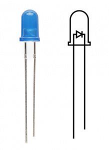
ESP32 Thing Plus, Bootstrap, SPIFFs, and ESPAsync

$
0
0

ESP32 Thing Plus, Bootstrap, SPIFFs, and ESPAsync a learn.sparkfun.com tutorial

Available online at: http://sfe.io/t1000

Introduction

This tutorial details how to turn an ESP32 Thing Plus into a good looking and responsive Web Server that controls four relays via I²C. The web page's theme and its' scalability from desktop to mobile phone will be made possible with Bootstrap - a toolkit for HTML, JS, and CSS. The Arduino Sketch is modified from the the ESPAsync File System Browser example code from the ESPAsync library and is used in conjunction with SPIFFS (SPI Flash File System) which turns your ESP32 into a hard drive that can hold all the dependent files for Bootstrap and the functions for turning on and off relays. This tutorial is based off a series of blog posts that share the intent and pit falls of this project as it grew. The first two in the series can be found here: Infrared tripwires to automate light switching and The ESP32 Web Server. Even if you decide to not use this to automate your lights, you can still use the information to create a good looking web page for your ESP32 that does something awesome; just make sure to leave a comment.

What's next?

You can check back here to see what's next to be updated, this will be updated as the tutorial grows. If you have any questions or suggestions, place them in the comments below.

To Do

  1. Update the Tutorial with the ESP32 Web Server section. Everything up to loading HTML, Bootstrap, and JS scripts onto ESP32 Thing Plus, this includes installing ESPAsync library and detailing what is needed in Bootstrap, resources for installing various requirements.
  2. Update tutorial with the Infrared tripwires Arduino Sketch and fill in details on the hardware hookup.
  3. Return to the ESP32 Web Server and introduce AJAX requests in place of straight GET requests.
  4. Implement I²C functions for relays.
  5. Add JSON files to store data related to WiFi settings and the state of each individual relay.
  6. Add a separate login web page when default WiFi settings don't connect to WiFi.
  7. Add trouble-shooting section to tutorial.

Hardware - FSBrowser Web Server

Hardware for the web server:

SparkFun Thing Plus - ESP32 WROOM

SparkFun Thing Plus - ESP32 WROOM

WRL-14689
$20.95
5
SparkFun Qwiic Quad Relay

SparkFun Qwiic Quad Relay

COM-15102
$29.95
1
Qwiic Cable - 200mm

Qwiic Cable - 200mm

PRT-14428
$1.50

Hardware Assembly - FSBrowser Web Server

Hardware - Infrared Trip Wires

Hardware for the Infrared Tripwires:

Resistor Kit - 1/4W (500 total)

Resistor Kit - 1/4W (500 total)

COM-10969
$7.95
155
Jumper Wires - Connected 6" (M/M, 20 pack)

Jumper Wires - Connected 6" (M/M, 20 pack)

PRT-12795
$1.95
2
SparkFun ESP8266 Thing - Dev Board

SparkFun ESP8266 Thing - Dev Board

WRL-13711
$16.95
69
IR Receiver Diode - TSOP38238

IR Receiver Diode - TSOP38238

SEN-10266
$1.95
Transistor - NPN, 50V 800mA (BC337)

Transistor - NPN, 50V 800mA (BC337)

COM-13689
$0.50
LED - Infrared 950nm

LED - Infrared 950nm

COM-09349
$0.95
2

Hardware Assembly - Infrared Trip Wire

This image shows a Fritzing diagram that outlines the circuits connections.

Libraries and necessary Software


learn.sparkfun.com | CC BY-SA 3.0 | SparkFun Electronics | Niwot, Colorado

SparkFun Pulse Oximeter and Heart Rate Monitor Hookup Guide

$
0
0

SparkFun Pulse Oximeter and Heart Rate Monitor Hookup Guide a learn.sparkfun.com tutorial

Available online at: http://sfe.io/t922

Introduction

The SparkFun Pulse Oximeter and Heart Rate Monitor is an I²C based biometric sensor. Utilizing two chips from Maxim Integrated, the SparkFun Pulse Oximeter and Heart Rate Monitor has both the MAX30101 biometric sensor and MAX32664 biometric hub. While the former does all the sensing, the latter is an incredibly small and fast Cortex M4 processor that handles all of the algorithmic calculations, digital filtering, pressure/position compensation, advanced R-wave detection and automatic gain control. We've combined them and written an Arduino Library with example code demonstrating basic to advanced features to help get you started utilizing the SparkFun Pulse Oximeter and Heart Rate Monitor into your next project. Or if you're looking to put these IC's into a final product, Maxim has provided some features to get FDA approval. Let's get started!

SparkFun Pulse Oximeter and Heart Rate Sensor - MAX30101 & MAX32664 (Qwiic)

SparkFun Pulse Oximeter and Heart Rate Sensor - MAX30101 & MAX32664 (Qwiic)

SEN-15219
$39.95
NOTE: This device is not intended to diagnose or treat any conditions.

Required Materials

To follow along with the example code used in this tutorial, you will also need the following materials. You may not need everything though depending on what you have. Add it to your cart, read through the guide, and adjust the cart as necessary.

SparkFun RedBoard Qwiic

SparkFun RedBoard Qwiic

DEV-15123
$19.95
4
USB micro-B Cable - 6 Foot

USB micro-B Cable - 6 Foot

CAB-10215
$4.95
12
Qwiic Cable - 100mm

Qwiic Cable - 100mm

PRT-14427
$1.50
IC Hook with Pigtail

IC Hook with Pigtail

CAB-09741
$4.95
8

If you need different size Qwiic cables, we offer a kit that contains many sizes but we also carry them individually as well. Make sure to use a Qwiic cable of sufficient length for flexibility. Short lengths like the 50mm Qwiic cable can be harder to obtain sensor readings.

SparkFun Qwiic Cable Kit

SparkFun Qwiic Cable Kit

KIT-15081
$7.95
1
Qwiic Cable - 100mm

Qwiic Cable - 100mm

PRT-14427
$1.50
Qwiic Cable - 500mm

Qwiic Cable - 500mm

PRT-14429
$1.95
Qwiic Cable - Breadboard Jumper (4-pin)

Qwiic Cable - Breadboard Jumper (4-pin)

PRT-14425
$1.50

Suggested Reading

Our Qwiic ecosystem keeps growing and growing with a host of new Qwiic enabled micro-controllers and sensors, check here for an overview.

Qwiic Connect System

We would also recommend taking a look at the following tutorials if you aren't familiar with them.

I2C

An introduction to I2C, one of the main embedded communications protocols in use today.

Serial Terminal Basics

This tutorial will show you how to communicate with your serial devices using a variety of terminal emulator applications.

How to Work with Jumper Pads and PCB Traces

Handling PCB jumper pads and traces is an essential skill. Learn how to cut a PCB trace, add a solder jumper between pads to reroute connections, and repair a trace with the green wire method if a trace is damaged.

RedBoard Qwiic Hookup Guide

This tutorial covers the basic functionality of the RedBoard Qwiic. This tutorial also covers how to get started blinking an LED and using the Qwiic system.

Hardware Overview

Power

You can provide 3.3V through the Qwiic connector on the "MAX32664 Side" of the board or through the 3V3 and GND labeled pins on the through hole header.

Power MAX30101 SidePower MAX32664 Side
MAX30101 SideMAX32664 Side

Qwiic Connector or I2C Pins

There are two Qwiic connectors on the board to easily get data from the sensor via I²C. Another option is to solder directly to the I²C plated through holes on the side of the board. Unfortunately, this board requires additional pins to function, see section below Additional Required pins.

I-squared-C options MAX30101 SideI-squared-C options MAX32664 Side
MAX30101 SideMAX32664 Side

We have many Qwiic sensors and Qwiic enabled microcontrollers. Check out our Qwiic Ecosystem page to get a glimpse of what else we have to offer.

Additional Required Pins

This board has two additional pins on it's header: the RESET and MFIO pin. These pins are required for the board to function because they determine if the board enters data collection mode or not. The Hardware Hookup section below will walk you through how to connect this board properly.

Additional required pins MAX30101 SideAdditional required pins MAX32664 Side
MAX30101 SideMAX32664 Side

MAX30101 - Pulse Oximeter and Heart Rate Monitor

The MAX30101 gets your heart rate (BPM) and blood oxygen levels (SpO2) through the process of photoplethysmography, which is the process of obtaining the aforementioned biometric data with light. The SparkFun Pulse Oximeter works by placing your finger gently on the sensor in which it shines red, infrared, and sometimes green light through your skin. The capillaries filled with blood under your skin will absorb this light, or not, and the MAX30101 sensor will read which light comes back. This light data will then be sent back to the Biometric Sensor Hub which handles all the calculations to determine heart rate and blood oxygen levels. Simple right?!

MAX30101 - Pulse Oximeter and Heart Rate Monitor

MAX32664 - Biometric Sensor Hub

The MAX32664 Biometric Sensor Hub is a very small Cortex M4 micro-controller dedicated to receiving the data it receives from the MAX30101 and running the calculations to determine heart rate and blood oxygen. When you're interfacing with the SparkFun Pulse Oximteter and Heart Rate Monitor, you are in effect interfacing with this wicked fast microcontroller. There are a multitude of settings to tailor the sensor to the persons you'll be monitoring made available through the Arduino Library we've written for it. Check the Arduino Examples below for more info!

MAX32664 - Biometric Sensor Hub

Jumpers

There a single set of jumpers on the MAX30101 side (non Qwiic connector side) of this product. This triple jumper labeled I2C connects pull-up resistors to the I²C data lines. If you're daisy chaining many I²C devices together, you may need to consider cutting these traces.

I2C Pull Up Resistor Jumper Pads

Hardware Hookup

This board is an I²C based board and so we've included a Qwiic Connector. However it isn't a "pure" Qwiic board as it requires two additional pins to be attached in order for it to function. However, you still don't need to solder if you have some of our IC hook with pigtail and in fact that's what I'll use for the following example. First, let's plug in our Qwiic Connector cable to either of the Qwiic connectors on the SparkFun Pulse Oximeter and Heart Rate Monitor.

Next we'll take the IC hooks and plug them into Redboard Qwiic into pins 5 and 4.

Qwiic Connector Attached to RedBoard Qwiic and an IC Hook on an Edge Connector

We'll then attach the claw side of the the IC hooks, the first in pin 5 to MFIO and the second plugged into pin 4 to RESET.

IC Hooks Connected to Pulse Oximeter and Heart Rate Monitor Breakout Board

When we get to sensing your pulse and blood oxygen levels, it's important that when you place your finger onto the sensor that you place it lightly and with consistent pressure. You can try to do this without any support, but I found that a rubber band is a good place to start.

Rubber Band for Consistent Pulse Reading

SparkFun Bio Sensor Arduino Library

Note: This example below assumes you are using the latest version of the Arduino IDE on your desktop. If this is your first time using Arduino, please review our tutorial on installing the Arduino IDE. If you have not previously installed an Arduino library, please check out our installation guide.

If you're using the RedBoard Qwiic and have never connected a CH340 device to your computer before, you may need to install drivers for the USB-to-serial converter. Check out our section on How to Install CH340 Drivers for help with the installation

We've written an Arduino library to make it even easier to get started with the SparkFun Pulse Oximeter and Heart Rate Monitor. The library will give you the full functionality of the sensor and provides example code to get the most our of your project. You can obtain these libraries through the Arduino Library Manager by searching SparkFun Bio Sensor Arduino Library. The second option is to download the ZIP file below from its GitHub repository to manually install it.

Reference Tables and Sensor Settings

This section shows some of the sensor's settings in clear tables so that you don't have to run to the datasheet for reference. It will also help to expand upon some unique characteristics of the SparkFun Bio Sensor Hub Library. Feel free to move beyond this section and jump to the Example Section below until this information becomes relevant in one of the examples.

BioData Information

As you'll see below, the library uses a type that is unique to the SparkFun Pulse Oximeter and Heart Rate Monitor. The name of this type is bioData and with it we'll be able to get at the biometric data that comes out of the board. Below is a table that shows all of the possible data stored within this mysterious new container, it has been named body for the table below and the following examples.

bioData Members Information Provided
body.heartrate Heart rate
body.oxygen Blood Oxygen Levels
body.confidenceThe Sensor's confidence in the reported data.
body.status Finger Detection
body.irLed Number of IR LED Samples
body.redLED Number of Red LED Samples

BioData Mode 2

In addition to the information above, mode 2 also gives the following two data points.

bioData Members Information Provided
body.rValue Sp02 r Value
body.extStatus Extended Finger Status Message

Finger Status

Below is a reference table for the body.status member which tells you if the sensor has detected a finger or some other object that is not a finger. It relays this information with four numbers: 0-3.

Status Number Description
0 No Object Detected
1 Object Detected
2 Object Other Than Finger Detected
3 Finger Detected

Below is a reference table for the body.exStatus member which is an expansion of the first finger status messaging. This is enabled in mode 2 and contains 8 different values.

Status Number Description
0 Success
1 Not Ready
-1 Object Detected
-2 Excessive Sensor Device Motion
-3 No object detected
-4 Pressing too hard
-5 Object other than finger detected
-6 Excessive finger motion

Pulse Width vs. Sample Collection

There is trade off between higher resolution (i.e. longer pulse width) and the number of samples that you can collect per second. The table below shows how the resolution and sample rate interact.

Samples/Second Pulse Width (uS)
69 118 215 411
50 O O O O
100 O O O O
200 O O O O
400 O O O O
800 O O O
1000 O O
1600 O
Resolution (bits) 15 16 17 18

Example 1: Config BPM Mode 1

In this first example, we'll read the heart rate and and blood oxygen level of the person we're monitoring. We'll also look at two other important values that the SparkFun Pulse Oximeter and Heart Rate Monitor provides so that you can ascertain whether the heart rate is accurate and whether a finger is being detected. Open the example up by heading to File>Examples>SparkFun Bio Sensor Hub Library>Example1_config_BPM_Mode1.ino .

Let's start at the top of Example 1: Config BPM Mode 1. Of note here, is that when we create an instance of the library called bioHub, we provide the SparkFun Pulse Oximeter's address but also the pin numbers used on the Arduino that the the RESET and MFIO are attached to: pin 4 and 5 respectively. These pins are necessary for the board's function, so make sure they're included here and also put in the correct order: RESET then MFIO pin.

language:c
#include <SparkFun_Bio_Sensor_Hub_Library.h>
#include <Wire.h>

// No other Address options.
#define DEF_ADDR 0x55

// Reset pin, MFIO pin
const int resPin = 4;
const int mfioPin = 5;

// Takes address, reset pin, and MFIO pin.
SparkFun_Bio_Sensor_Hub bioHub(DEF_ADDR, resPin, mfioPin); 

bioData body;  

Just above you'll see this funky type called bioData. This is a type that is unique to the SparkFun Pulse Oximeter and Heart Rate Monitor and it holds all the Biometric data of the sensor: Heart rate, confidence, blood oxygen levels, finger detection, led data, etc. I've provided a table just above that describes all the available information that it holds (see Reference Tables and Sensor Settings). Later in the example, we'll see how it's used.

Next let's look at the setup. There are two functions to point out. First, the bioHub.begin() function call makes sure that we can communicate with the sensor. Secondly and equally as important bioHub.configBPM(MODE_ONE), configures the SparkFun Pulse Oximeter's settings and enables all of the necessary algorithms within the sensor to begin collecting data. Which data is collected depends on how the sensor is configured. You'll get biometric data with bioHub.configBPM(), you can just get LED data with bioHub.configSensor(), or you can get all the data with bioHub.configSensorBPM(). As soon as this is called, the sensor will begin collecting data. However, the sensor lags a couple of seconds behind when it begins sensing the data and when it actually gives that data to the user. I've put a four second delay at the end of setup to give some time for the data to catch up.

language:c
void setup(){

  Serial.begin(115200);

  Wire.begin();
  int result = bioHub.begin();
  if (!result)
    Serial.println("Sensor started!");
  else
    Serial.println("Could not communicate with the sensor!!!");

  Serial.println("Configuring Sensor...."); 
  int error = bioHub.configBpm(MODE_ONE); // Configuring just the BPM settings. 
  if(!error){
    Serial.println("Sensor configured.");
  }
  else {
    Serial.println("Error configuring sensor.");
    Serial.print("Error: "); 
    Serial.println(error); 
  }
  // Data lags a bit behind the sensor, if you're finger is on the sensor when
  // it's being configured this delay will give some time for the data to catch
  // up. 
  delay(4000); 

}

In the main loop, the biometric data is collected from the SparkFun Pulse Oximeter and Heart Rate Monitor with the function bioHub.readBpm(), and it's saved to body. Now to get at that information, we call body.heartrate, body.oxygen, etc. Easy!

language:c
void loop(){

    // Information from the readBpm function will be saved to our "body"
    // variable.  
    body = bioHub.readBpm();
    Serial.print("Heartrate: ");
    Serial.println(body.heartRate); 
    Serial.print("Confidence: ");
    Serial.println(body.confidence); 
    Serial.print("Oxygen: ");
    Serial.println(body.oxygen); 
    Serial.print("Status: ");
    Serial.println(body.status); 
    delay(250); // Slowing it down, we don't need to break our necks here.
}

A note on body.confidence and body.status. The confidence level is the sensor's confidence in the heart rate that was reported. The status is whether or not the sensor has detected a finger. See the table above for the four possible status numbers and what they mean.

Example 2: Config BPM Mode 2

As opposed to Example 1, In Example 2's setup, we give the argument MODE_TWO to bioHub.configBPM() to get more information from the SparkFun Pulse Oximeter and Heart Rate Monitor. Specifically we'll get an extended finger status and the R value of the blood oxygen data.

language:c
Serial.println("Configuring Sensor...."); 
int error = bioHub.configBpm(MODE_TWO); // Configuring just the BPM settings. 
if(!error){
    Serial.println("Sensor configured.");
}
else {
    Serial.println("Error configuring sensor.");
    Serial.print("Error: "); 
    Serial.println(error); 
}

Simple right? Nothing else changes except that when we pull the data we now have access to more data: body.extStatus and body.rValue.

language:c
void loop(){

    // Information from the readBpm function will be saved to our "body"
    // variable.  
    body = bioHub.readBpm();
    Serial.print("Heartrate: ");
    Serial.println(body.heartRate); 
    Serial.print("Confidence: ");
    Serial.println(body.confidence); 
    Serial.print("Oxygen: ");
    Serial.println(body.oxygen); 
    Serial.print("Status: ");
    Serial.println(body.status); 
    Serial.print("Extended Status: ");
    Serial.println(body.extStatus); 
    Serial.print("Blood Oxygen R value: ");
    Serial.println(body.rValue); 
    delay(250); // Slowing it down, we don't need to break our necks here.
}

Check the reference table above under Finger Status for more information on what each number means, there are eight. The R value refers to a correlation coefficient used to determine a statistical relationship between two variables: blood oxygen and a optical plate placed over the sensor. This does not refer to the glass shield on the sensor but rather a shield that would be placed over the sensor if you decided to implement this into a final product. In other words the company that manufactures this IC, Maxim Integrated has given the user a way to get faster FDA approval when using this IC in a final product. You can read more about that here. For those of us just tinkering in a project it has no Real value. Get it?

Example 3: AGC Settings

I won't break down this example code because you have all the necessary tools to get you started with the SparkFun Pulse Oximeter and Heart Rate Monitor. However, there are a few more settings to fine tune the Automatic Gain Control (AGC) algorithm that the MAX32664 Sensor uses to automatically adjust the MAX30101 on the fly. This particular algorithm is being used in the first example because it's turned on automatically with the configBPM() function call. Configuring the sensor to give both sensor and biometric data (configSensorBpm()) does not have this algorithm enabled and so relies on the default settings of the MAX30101 sensor, unless of course you have configured the pulse width and sample collection yourself. In Example 4 we talk about how to modify these values.

Example 4: Adjust LED Values

The fourth example will show you how to adjust the accuracy of the SparkFun Pulse Oximeter and Heart Rate Monitor. We'll do this by adjusting the length of time that the LEDs inside the MAX30101 pulse, which will also impact how many samples we can get at a time. So we'll talk about these two settings and how they play against each other. Open the example up by heading to File>Examples>SparkFun Bio Sensor Hub Library>Example4_config_LEDs_BPM.ino .

Starting at the top, we assign the reset and mfio pins to pin 4 and 5 respectively. Below that we have two variables that will store the pulse width and the sample rate: width and samples. A longer pulse width changes the amount of time that the sensor's LEDs shine into the finger before ascertaining how much light was absorbed. This results in higher resolution data as the finger is fully illuminated before collecting data. However, the trade off is the sensor has less time to collect samples. For each increasing pulse width setting, there is a decrease in the amount of samples that can be collected. Check the table above under Pulse Width vs Sample Collection above to see all possible interactions.

language:c
const int resPin = 4;
const int mfioPin = 5;

// Possible widths: 69, 118, 215, 411us
int width = 411; 
// Possible samples: 50, 100, 200, 400, 800, 1000, 1600, 3200 samples/second
// Not every sample amount is possible with every width; check out our hookup
// guide for more information.
int samples = 400; 
int pulseWidthVal;
int sampleVal;

// Takes address, reset pin, and MFIO pin.
SparkFun_Bio_Sensor_Hub bioHub(DEF_ADDR, resPin, mfioPin); 

bioData body; 

I'll reiterate what's stated in the first example. Just above you'll see this funky type called bioData. This is a type that is unique to the SparkFun Pulse Oximeter and Heart Rate Monitor and it holds all the Biometric data of the sensor: Heart rate, confidence, blood oxygen levels, finger detection, led data, etc. There is a table above under Reference Tables and Sensor Settings that displays the information available in bioData.

Unlike our first example, in this one we're we are calling bioHub.configSensorBpm(MODE_ONE) which tells the MAX32664 to give us both LED data as well as biometric data and to load it up into bioData. We'll see this come into play later on in the loop below.

language:c
int error = bioHub.configSensorBpm(MODE_ONE); // Configure Sensor and BPM mode 
if(!error){
    Serial.println("Sensor configured.");
}
else {
    Serial.println("Error configuring sensor.");
    Serial.print("Error: "); 
    Serial.println(error); 
}

To set the pulse width, there is a call to bioHub.setPulseWidth(width), giving it the variable width that we defined above that holds the value 411µS. We then set the sample rate with bioHub.setSampleRate(samples), again using the variable defined above. If you were to set a sample rate above what is capable at a particular pulse width, the sensor will automatically set it to the highest possible setting at that rate automatically. After configuring both settings, both values are read back with calls to bioHub.readPulseWidth() and bioHub.readSampleRate().

language:c
error = bioHub.setPulseWidth(width);
if (!error){
    Serial.println("Pulse Width Set.");
}
else {
    Serial.println("Could not set Pulse Width.");
    Serial.print("Error: "); 
    Serial.println(error); 
}

// Check that the pulse width was set. 
pulseWidthVal = bioHub.readPulseWidth();
Serial.print("Pulse Width: ");
Serial.println(pulseWidthVal);

// Set sample rate per second. Remember that not every sample rate is
// available with every pulse width. Check hookup guide for more information.  
error = bioHub.setSampleRate(samples);
if (!error){
    Serial.println("Sample Rate Set.");
}
else {
    Serial.println("Could not set Sample Rate!");
    Serial.print("Error: "); 
    Serial.println(error); 
}

// Check sample rate.
sampleVal = bioHub.readSampleRate();
Serial.print("Sample rate is set to: ");
Serial.println(sampleVal); 

// Some time to read your settings.
delay(2000);

Here in the loop, we have a bit more information being printed out to the serial monitor than in the first example. Specifically there are the body.irLed and body.redLed data points which give us the number of light samples collected by the sensor for the respective LEDs.

language:c
void loop(){

    // Information from the readSensor function will be saved to our "body"
    // variable.  
    body = bioHub.readSensorBpm();
    Serial.print("Infrared LED counts: ");
    Serial.println(body.irLed); 
    Serial.print("Red LED counts: ");
    Serial.println(body.redLed); 
    Serial.print("Heartrate: ");
    Serial.println(body.heartRate); 
    Serial.print("Confidence: ");
    Serial.println(body.confidence); 
    Serial.print("Blood Oxygen: ");
    Serial.println(body.oxygen); 
    Serial.print("Status: ");
    Serial.println(body.status); 
    delay(500); // Slowing it down, we don't need to break our necks here.
}

Troubleshooting

Heart Rate is Non-Existent!

It can't be reiterated enough, the sensor needs light but consistent pressure on the full plate of the sensor. I've also found that it's much easier to get readings from a warm hand then a cold one. If you continue to have issues check the finger status and extended finger status to get a hint at what the sensor is seeing. Check the reference table and scroll down to Finger Status to see all of the various error messages that are given by these status messages.

Error Configuring Sensor

First this products is not "pure" Qwiic because it requires that the reset and mfio pin be connected to your micro-controller. Check the hardware hookup section above for explicit instructions on how to do this.

Error Table

If you continue to have trouble configuring your sensor after checking that you've correctly hooked it up, then perhaps an error message can narrow it down for you. Below is a list of most of the error values from the datasheet. The final error message of incorrect paramater was implemented in the library to convey that an incorrect argument was used for any particular function.

Error Description
0x01 ERROR UNAVAILABLE COMMAND
0x02 ERROR UNAVAILABLE FUNCTION
0x03 ERROR DATA FORMAT
0x04 ERROR INPUT VALUE
0x05 ERROR TRY AGAIN
0xFF (255) ERROR UNKNOWN
0xEE (238) INCORRECT PARAMETER

Resources and Going Further

For more on the AS3935, check out the links below:

Need some other sensor to measure biometrics for your project? Check out some of the ones listed below.

MyoWare Muscle Sensor Development Kit

MyoWare Muscle Sensor Development Kit

KIT-14409
$82.95
2
MyoWare Muscle Sensor

MyoWare Muscle Sensor

SEN-13723
$37.95
6
Fingerprint Scanner - TTL (GT-521F32)

Fingerprint Scanner - TTL (GT-521F32)

SEN-14518
$35.95
4
SparkFun Single Lead Heart Rate Monitor - AD8232

SparkFun Single Lead Heart Rate Monitor - AD8232

SEN-12650
$19.95
17

Need some inspiration for your next project? Check out some of these related tutorials to sense your environment!

Hackers in Residence - Hacking MindWave Mobile

Review, teardown, and hacking tutorial for the MindWave Mobile, a $99 commercial grade EEG sensor.

AD8232 Heart Rate Monitor Hookup Guide

Learn how to create your very own heart rate monitor.

MyoWare Muscle Sensor Kit

Line of products to work with the MyoWare muscle sensor from Advancer Technologies

Getting Started with Walabot

See through walls, track objects, monitor breathing patterns, and more using the power of radio frequency with the Walabot! In this tutorial, we will explore Walabot’s features using the Software Demo Kit (SDK) on Windows and the Application Programming Interface (API) on Linux-based distributions for embedded projects.

learn.sparkfun.com | CC BY-SA 3.0 | SparkFun Electronics | Niwot, Colorado

Hookup Guide for the Qwiic Motor Driver

$
0
0

Hookup Guide for the Qwiic Motor Driver a learn.sparkfun.com tutorial

Available online at: http://sfe.io/t934

Introduction

The Qwiic Motor Driver takes all the great features of the Serial Controlled Motor Driver and mini-sizes them, adding Qwiic ports for plug and play functionality. Boasting the same PSOC and 2-channel motor ports, the QWIIC Motor Driver is designed to communicate over I2C, but UART is also available.

SparkFun Qwiic Motor Driver

SparkFun Qwiic Motor Driver

ROB-15451
$14.95

Required Materials

To follow along with this tutorial, you will need the following materials. You may not need everything though depending on what you have. Add it to your cart, read through the guide, and adjust the cart as necessary.

Suggested Reading

If you aren’t familiar with the following concepts, we recommend you read over these tutorials before continuing.

Serial Communication

Asynchronous serial communication concepts: packets, signal levels, baud rates, UARTs and more!

I2C

An introduction to I2C, one of the main embedded communications protocols in use today.

Motors and Selecting the Right One

Learn all about different kinds of motors and how they operate.

Logic Levels

Learn the difference between 3.3V and 5V devices and logic levels.

Bi-Directional Logic Level Converter Hookup Guide

An overview of the Bi-Directional Logic Level Converter, and some example circuits to show how it works.

Serial Controlled Motor Driver Hookup Guide

Hookup guide for the Serial Controlled Motor Driver

Hardware Overview

Let's look at some of the various features of the hardware.

Features:

  • 1.5 A peak drive per channel, 1.2 A steady state
  • Operates from 3 to 11 volts with 12v absolute max
  • 3.3V default VCC and logic
  • 127 levels of DC drive strength.
  • Controllable by I2C or TTL UART signals
  • Direction inversion on a per motor basis
  • Global Drive enable
  • Exposed small heat sink shape
  • Several I2C addresses, default UART bauds available

Front of Qwiic Motor Driver

Power

There are two separate power circuits on this board . Power for the motors is supplied through the VIN Connectors - you can provide anywhere from 3.3V to 11V to the "MAX 11V" and "GND" connections. Power for the PSOC and logic circuits is provided by the 3.3V inputs on the Qwiic connectors. Both are needed for proper functioning.

VIn inputs

Motor Power Ports: Ground (Left) - VIN(Right)

Qwiic Connectors

There are two Qwiic connectors on the board such that you can provide power or daisy-chain the boards should you choose to do so. If you're unfamiliar with our Qwiic system, head on over to our Qwiic page to see the advantages!

Qwiic connectors on either side of the board

Motor Ports

The screw pin terminals at the top of the board allow for two motor connections. They are labeled on the backside of the board.

Screw terminals for motor inputs

From left to right on the front: B2-B1-A2-A1
Function / Connection
GroupNameDirectionDescriptionUARTI2C
Motor PortA1OWinding of first addressable locationMotor A winding
A2OWinding of first addressable locationMotor A winding
B1OWinding of second addressable locationMotor B winding
B2OWinding of second addressable locationMotor B winding

Jumpers

Jumper Usage Table

There are 2 sets of jumpers to configure on this board. There are pull-up enables for I2C and 4 config bits that select operational mode.

NameDescriptionUsage
I2C JumpersI2C pull-up enableOpening these disables theI2C pull-up resistors used for I2C communication. If multiple I2C devices are being used, these pull-ups should be disabled on all but one device. If UART is being used, the pull-up resistors should be disabled.
Address JumpersSerial and function selectionThe config bits are 4 bits that form a configuration nybble. A closed jumper is a '1' and an open jumper is a '0'. See config table for more information.

I2C Pull-Up Jumpers

I2C Jumpers on the lower right side of the back of the board

Address Bits

The configuration is set by encoding a number into the 4 config bits on the bottom of the board. Close a jumper to indicate a 1, or leave it open to indicate a 0.

Address jumpers on the back of the board

Use this table to see what the user port, address, and expansion port will become in each configuration:

PatternModeUser PortUser AddressExpansion Port
0000UART at 9600UARTN/AMaster
0011I2CI2C0x58Master
0100I2CI2C0x59Master
0101I2CI2C0x5AMaster
0110I2CI2C0x5BMaster
0111I2CI2C0x5CMaster
1000I2CI2C0x5DMaster
1001I2CI2C0x5EMaster
1010I2CI2C0x5FMaster
1011I2CI2C0x60Master
1100I2CI2C0x61Master
1101UART at 57600UARTN/AMaster
1110UART at 115200UARTN/AMaster
1111N/AReservedN/AN/A

Bold text is the default setting for the Qwiic Motor Driver

Thermal Conduction Area

The Qwiic Motor Driver is designed to operate small robot drive motors without a heatsink; we were able to run up to about 1.1A continuous current without going above 100°C. If you find that you need a heatsink, you can use our Theragrip Thermal Tape to attach three Small Heat Sinks across the thermal conduction area on the back of the board.

Thermal conduction area on the back of the board

If you need more information on how to determine whether or not you need a heat sink, kick on over to the Serial Controlled Motor Driver Hookup Guide and scroll down to Typical Application Motors and Heat Sinking.

Small heatsinks on the back of the Qwiic Motor Driver

Small Heatsinks on the back of the Qwiic Motor Driver

Software Setup

Note: This code/library has been written and tested on Arduino IDE version 1.8.5. Otherwise, make sure you are using the latest stable version of the Arduino IDE on your desktop. If this is your first time using Arduino, please review our tutorial on installing the Arduino IDE. If you have not previously installed an Arduino library, please check out our installation guide.

Installing Arduino

If you haven't used the Arduino IDE before, head on over to our Installing the Arduino IDE tutorial to get set up:

Installing Arduino IDE

March 26, 2013

A step-by-step guide to installing and testing the Arduino software on Windows, Mac, and Linux.

Getting the Arduino Library

The Qwiic Motor Driver uses the same Arduino Library as the Serial Controlled Motor Driver (hereafter referred to as SCMD). To get the Arduino library, either download and install it from Github or use the Arduino Library Manager.

Download the Github repository

Visit the GitHub repository to download the most recent version of the library, or click the link below:

Use the library manager or install in the Arduino IDE

In the Library Manager, search for Serial Controlled Motor Driver. For help installing the library, check out our How To Install An Arduino Library tutorial.

Installing an Arduino Library

January 11, 2013

How do I install a custom Arduino library? It's easy! This tutorial will go over how to install an Arduino library using the Arduino Library Manager. For libraries not linked with the Arduino IDE, we will also go over manually installing an Arduino library.

Experiment 1: Testing the Motors

Let's start by hooking up some motors and making sure they're running. Since the Qwiic Motor Driver uses the same PSOC as the Serial Controlled Motor Driver, the same examples will work with minor modifications.

Hardware Hookup

Hardware Hookup Fritzing image Experiment 1

Click the image for a closer look

Testing the Motors

The following test is essentially the TwoMotorRobot.ino example from the SCMD library, but with a few minor changes to account for the defaults of the Qwiic Motor Driver.

Copy and paste the following code into your Arduino browser and upload.

language:c
//This example drives a robot in left and right arcs, driving in an overall wiggly course.
//  It demonstrates the variable control abilities. When used with a RedBot chassis,
//  each turn is about 90 degrees per drive.
//
//  Pin 8 can be grounded to disable motor movement, for debugging.

#include <Arduino.h>
#include <stdint.h>
#include "SCMD.h"
#include "SCMD_config.h" //Contains #defines for common SCMD register names and values
#include "Wire.h"

SCMD myMotorDriver; //This creates the main object of one motor driver and connected slaves.

void setup()
{
  pinMode(8, INPUT_PULLUP); //Use to halt motor movement (ground)

  Serial.begin(9600);
  Serial.println("Starting sketch.");

  //***** Configure the Motor Driver's Settings *****//
  //  .commInter face is I2C_MODE 
  myMotorDriver.settings.commInterface = I2C_MODE;

  //  set address if I2C configuration selected with the config jumpers
  myMotorDriver.settings.I2CAddress = 0x5D; //config pattern is "1000" (default) on board for address 0x5D

  //  set chip select if SPI selected with the config jumpers
  myMotorDriver.settings.chipSelectPin = 10;

  //*****initialize the driver get wait for idle*****//
  while ( myMotorDriver.begin() != 0xA9 ) //Wait until a valid ID word is returned
  {
    Serial.println( "ID mismatch, trying again" );
    delay(500);
  }
  Serial.println( "ID matches 0xA9" );

  //  Check to make sure the driver is done looking for slaves before beginning
  Serial.print("Waiting for enumeration...");
  while ( myMotorDriver.ready() == false );
  Serial.println("Done.");
  Serial.println();

  //*****Set application settings and enable driver*****//

  //Uncomment code for motor 0 inversion
  //while( myMotorDriver.busy() );
  //myMotorDriver.inversionMode(0, 1); //invert motor 0

  //Uncomment code for motor 1 inversion
  while ( myMotorDriver.busy() ); //Waits until the SCMD is available.
  myMotorDriver.inversionMode(1, 1); //invert motor 1

  while ( myMotorDriver.busy() );
  myMotorDriver.enable(); //Enables the output driver hardware

}

#define LEFT_MOTOR 0
#define RIGHT_MOTOR 1
void loop()
{
  //pass setDrive() a motor number, direction as 0(call 0 forward) or 1, and level from 0 to 255
  myMotorDriver.setDrive( LEFT_MOTOR, 0, 0); //Stop motor
  myMotorDriver.setDrive( RIGHT_MOTOR, 0, 0); //Stop motor
  while (digitalRead(8) == 0); //Hold if jumper is placed between pin 8 and ground

  //***** Operate the Motor Driver *****//
  //  This walks through all 34 motor positions driving them forward and back.
  //  It uses .setDrive( motorNum, direction, level ) to drive the motors.

  //Smoothly move one motor up to speed and back (drive level 0 to 255)
  for (int i = 0; i < 256; i++)
  {
    myMotorDriver.setDrive( LEFT_MOTOR, 0, i);
    myMotorDriver.setDrive( RIGHT_MOTOR, 0, 20 + (i / 2));
    delay(5);
  }
  for (int i = 255; i >= 0; i--)
  {
    myMotorDriver.setDrive( LEFT_MOTOR, 0, i);
    myMotorDriver.setDrive( RIGHT_MOTOR, 0, 20 + (i / 2));
    delay(5);
  }
  //Smoothly move the other motor up to speed and back
  for (int i = 0; i < 256; i++)
  {
    myMotorDriver.setDrive( LEFT_MOTOR, 0, 20 + (i / 2));
    myMotorDriver.setDrive( RIGHT_MOTOR, 0, i);
    delay(5);
  }
  for (int i = 255; i >= 0; i--)
  {
    myMotorDriver.setDrive( LEFT_MOTOR, 0, 20 + (i / 2));
    myMotorDriver.setDrive( RIGHT_MOTOR, 0, i);
    delay(5);
  }
}

What You Should See

The code goes through and establishes communication with the motor driver and then runs each motor in arcs, resulting in a "wiggly pattern".

Things to note:

  • Serial.begin is periodically run until the returned ID word is valid.
  • Setup waits for isReady() to become true before going on to the drive section
  • One motor is inverted by command at setup. Do it here so you don't have to mess with it later.
  • enable() is called to connect the drivers to the PWM generators.
  • LEFT_MOTOR and RIGHT_MOTOR are defined to ease use of the setDrive( ... ) function.

See the Arduino Library Reference section of the Serial Controlled Motor Driver Hookup Guide for more information on the functions defined in the Arduino library.

Experiment 2: Interactive Commands with UART

This example demonstrates the basic commands, plus some direct register access possible with only a UART available. This type of program could be easily run from a script from a more classic PC where I2C isn't available.

Interactive UART

Requirements

  • Computer serial terminal set to 9600 baud.
  • Terminal set to send CR and LF (Carriage return and line feed).
  • Config jumpers set to '0000', or all open.
  • I2C PU jumper fully open
  • FTDI Basic or Serial Basic - either will work but ensure you have the 3.3V version

Address Jumper 3 and I2C Pullup Jumpers are cut

Make sure the Address Jumper 3 and I2C Pullup Jumpers are cut as you see here.

Connect the FTDI to the Qwiic Motor Driver as you see in the Fritzing diagram below. Attach two motors to the driver, one between A1 and A2, and the other between B1 and B2.

Example 2 Fritzing image

Click the image for a closer look

Example Commands

When you're ready, make sure you have the correct COM port selected in your Arduino IDE, open a Serial Monitor, and send the following commands:

"R01"

This will read the ID register and return 0xA9

"M0F50"

This will tell motor 0 to drive at half speed, forward -- But nothing will happen yet!

"E"

This will enable all drivers. Motor 0 should begin spinning at half speed.

"M1R100"

This will tell motor 1 to drive at full speed in reverse. Now both should be spinning opposite directions.

"D"

D will disable both motors, which will stop spinning.

See the section UART Commands in the Serial Controlled Motor Driver Hookup Guide for a full command listing.

Troubleshooting

Resources and Going Further

Need inspiration? Check out some of the Qwiic or motor related tutorials!

IoT Power Relay

Using the ESP32 to make a web-configured timed relay.

ESP32 LoRa 1-CH Gateway, LoRaWAN, and the Things Network

Using the ESP32 LoRa 1-CH Gateway as a gateway and device, and pushing data to The Things Network.

GPS-RTK Hookup Guide

Find out where you are! Use this easy hook-up guide to get up and running with the SparkFun high precision GPS-RTK board.

Qwiic Quad Relay Hookup Guide

SparkFun’s Qwiic Quad Relay is a product designed for switching not one but four high powered devices from your Arduino or other low powered microcontroller using I2C.

Motors and Selecting the Right One

Learn all about different kinds of motors and how they operate.

ReconBot with the Tessel 2

Build a robot with the Tessel 2 that you can control from a browser on your phone or laptop.

Serial Controlled Motor Driver Hookup Guide

Hookup guide for the Serial Controlled Motor Driver

micro:bot Kit Experiment Guide

Get started with the moto:bit, a carrier board for the micro:bit that allows you to control motors, and create your own robot using this experiment guide for the micro:bot kit.

learn.sparkfun.com | CC BY-SA 3.0 | SparkFun Electronics | Niwot, Colorado
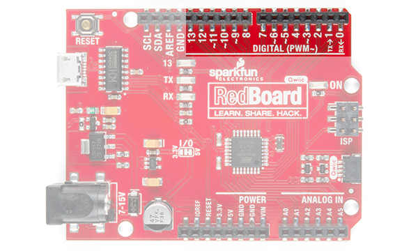

Hookup Guide for the SparkFun Artemis Thing Plus

$
0
0

Hookup Guide for the SparkFun Artemis Thing Plus a learn.sparkfun.com tutorial

Available online at: http://sfe.io/t928

Introduction

Our Artemis line would not be complete without including the Feather-compatible SparkFun Artemis Thing Plus. With 21 GPIO Pins - all PWM and interrupt capable - there are 2 I2C buses available, as well as SPI and UART. We've included the digital MEMS microphone that allows for always-on voice commands with TensorFlow and machine learning, and the Qwiic connector makes using our Qwiic sensors as easy as plug and play!

SparkFun Thing Plus - Artemis

SparkFun Thing Plus - Artemis

WRL-15574
$20.95

Required Materials

You'll need the Artemis Thing Plus and a USB C cable. Any USB C cable should work, including the one that probably came with your phone charger.

USB 2.0 Cable A to C - 3 Foot

USB 2.0 Cable A to C - 3 Foot

CAB-15092
$3.95
SparkFun Thing Plus - Artemis

SparkFun Thing Plus - Artemis

WRL-15574
$20.95

Suggested Reading

If you aren't familiar with the Qwiic system, we recommend reading here for an overview.

Qwiic Connect System

We also recommend checking out these tutorials before continuing:

I2C

An introduction to I2C, one of the main embedded communications protocols in use today.

Designing with the SparkFun Artemis

Let's chat about layout and design considerations when using the Artemis module.

Artemis Development with Arduino

Get our powerful Artemis based boards (Artemis Nano, BlackBoard Artemis, and BlackBoard Artemis ATP) blinking in less than 5 minutes using the SparkFun Artemis Arduino Core!

Hardware Overview

The Artemis Thing Plus has a wide range of functionality to get through, so let's have a look, shall we?

Features:

  • 1M Flash / 384k RAM
  • 48MHz / 96MHz turbo available
  • 21 GPIO Pins - all interrupt capable
  • 21 PWM Channels
  • Built in BLE radio
  • 8 ADC channels with 14-bit precision
  • 2 I2C buses
  • 1 SPI bus
  • 2 UARTs
  • PDM Digital Microphone
  • I2S Interface
  • Qwiic Connector

High res photo of front of board

Serial and JTAG Programming

The RedBoard Artemis Thing Plus has two methods for programming. The most common is the USB C connector that operates as a USB to serial bridge. By simply pressing 'Upload' in the Arduino IDE or 'make bootload' from the SDK the firmware on Artemis is updated.

USB-C port for programming the Artemis Thing Plus

Click the image for a closer look

We use the CH340E on the RedBoard Artemis Thing Plus. The driver should automatically install on most operating systems. However, there is a wide range of operating systems out there. You may need to install drivers the first time you connect the chip to your computer's USB port or when there are operating system updates. For more information, check out our How to Install CH340 Drivers Tutorial.

How to Install CH340 Drivers

August 6, 2019

How to install CH340 drivers (if you need them) on Windows, Mac OS X, and Linux.

The second method is JTAG programming. An unpopulated JTAG footprint is available for more advanced users who need breakpoint level debugging. We recommend checking out our JTAG section for the compatible male header and a compatible JTAG programmer and debugger.

JTag ports for programming the Artemis Thing Plus

Click the image for a closer look

GPIO

The Artemis Thing Plus has 21 available GPIO pins on either side of the board. In addition, there are separate IO for a user button and LED. The LED pin supports PWM but the button's pin does not. The Artemis Thing Plus Schematic can give you more information on which of the Apollo3 pads are broken out for the Thing Plus. You can also cross reference this with the Apollo3 Pad Map.


GPIO Pin RailsUser Button and LED

Click on either image for a closer look

Qwiic and I2C

The I2C pins on the Artemis Thing Plus are labeled SDA and SCL on the back of the board. They are controlled in the Arduino IDE using Wire.begin(), Wire.read(), etc. While pins 16/17 use Wire1, the Qwiic connector uses Wire so you can use SparkFun's Qwiic ecosystem (there's over 50 boards and more every week!).


Front View: Qwiic Connector and I2C Pins 16 and 17Back View: Pins 16/SDA1 and 17/SCL1

Click on either image for a closer look

Mic and RTC

The Artemis excels at low power voice recognition. To enable this we've included a PDM MEMS microphone on the board. Additionally, the Artemis module can operate an RTC given an external 32kHz crystal so we've included that was well.

PDM Microphone and RTC on RedBoard Artemis Thing Plus

Click the image for a closer look

Software Setup

The Artemis Thing Plus is capable of running both Arduino and the more advanced Ambiq HAL/SDK. Checkout these tutorials to get you up and blinking in 5 minutes!

Artemis Development with Arduino

June 20, 2019

Get our powerful Artemis based boards (Artemis Nano, BlackBoard Artemis, and BlackBoard Artemis ATP) blinking in less than 5 minutes using the SparkFun Artemis Arduino Core!

Using SparkFun Edge Board with Ambiq Apollo3 SDK

March 28, 2019

We will demonstrate how to get started with your SparkFun Edge Board by setting up the toolchain on your computer, examining an example program, and using the serial uploader tool to flash the chip.

Troubleshooting

Resources and Going Further

Did you know you can use the SparkFun Artemis Thing Plus as the starting point of your very own Artemis product? Get the design files from our repo here and edit them using Eagle PCB!

For more information on the RedBoard Artemis and the Artemis module itself, check out the links below:

You've now explored the board, let's get blinking with Arduino! Or perhaps you want to learn a little more about the Artemis module itself. Checkout these tutorials!

Designing with the SparkFun Artemis

Let's chat about layout and design considerations when using the Artemis module.

Artemis Development with Arduino

Get our powerful Artemis based boards (Artemis Nano, BlackBoard Artemis, and BlackBoard Artemis ATP) blinking in less than 5 minutes using the SparkFun Artemis Arduino Core!

Hookup Guide for the BlackBoard Artemis Nano

Get started with the powerful BlackBoard Artemis Nano

Did you know the Artemis is compatible with our Qwiic line? Checkout these products that simply plug in and work!

SparkFun Spectral Sensor Breakout - AS7262 Visible (Qwiic)

SparkFun Spectral Sensor Breakout - AS7262 Visible (Qwiic)

SEN-14347
$25.95
1
Qwiic Cable - 500mm

Qwiic Cable - 500mm

PRT-14429
$1.95
SparkFun Triad Spectroscopy Sensor - AS7265x (Qwiic)

SparkFun Triad Spectroscopy Sensor - AS7265x (Qwiic)

SEN-15050
$64.95
3
SparkFun Qwiic Kit for Raspberry Pi

SparkFun Qwiic Kit for Raspberry Pi

KIT-15367
$54.95

learn.sparkfun.com | CC BY-SA 3.0 | SparkFun Electronics | Niwot, Colorado
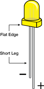
SparkFun Edge Hookup Guide

$
0
0

SparkFun Edge Hookup Guide a learn.sparkfun.com tutorial

Available online at: http://sfe.io/t878

Introduction

With the SparkFun Edge Development Board and the SparkFun Edge 2 Development Board, edge computing is here! You've probably heard of this latest entry to the long lineage of tech buzzwords like "IoT,""LoRa," and "cloud" before it, but what is the edge and why does it matter? The cloud is impressively powerful but all-the-time connections require power and connectivity that may not be available. Edge computing handles discrete tasks such as determining if someone said 'start washer' and responding accordingly. The audio analysis is done at the "edge" rather than on the web. This dramatically reduces costs and complexity while limiting potential data privacy leaks.

SparkFun Edge Development Board - Apollo3 Blue

SparkFun Edge Development Board - Apollo3 Blue

DEV-15170
$14.95
10
SparkFun Edge 2 Development Board - Artemis

SparkFun Edge 2 Development Board - Artemis

DEV-15420
$15.95

So now that you've embarked upon the journey to the Edge, let's take a moment to get off on the right foot. In this hookup guide we will get familiar with the hardware available and how to connect to your computer, then we'll point you in the right direction to begin writing awesome applications using machine learning!

Required Materials

To follow along with this tutorial, you will need the following materials. You may not need everything though depending on what you have. Add it to your cart, read through the guide, and adjust the cart as necessary.

Suggested Reading

If you aren’t familiar with the following concepts, we recommend checking out these tutorials before continuing.

Serial Terminal Basics

This tutorial will show you how to communicate with your serial devices using a variety of terminal emulator applications.

Using SparkFun Edge Board with Ambiq Apollo3 SDK

We will demonstrate how to get started with your SparkFun Edge Board by setting up the toolchain on your computer, examining an example program, and using the serial uploader tool to flash the chip.

Suggested Viewing

Hardware Overview

Microcontroller

Both the Edge and the Edge 2 use the Apollo3 Blue - the cutting-edge of high efficiency microcontrollers. This small BGA package packs quite a punch! While the Edge Development Board uses the microcontroller on it's own, the Edge 2 wraps the Apollo3 in the multi-functional, FCC certified Artemis Module.

  • 32-bit ARM Cortex-M4F processor with Direct Memory Access
  • 48MHz CPU clock, 96MHz with TurboSPOT™
  • Extremely low-power usage: 6uA/MHz
  • 1MB Flash
  • 384KB SRAM
  • Dedicated Bluetooth processor with BLE 5

15170 - Edge Board15420 - Edge 2 Board

Sensors

Such a formidable microcontroller would be wasted without a suite of cool sensors to use with it - that's why we've included two microphones, a 3-axis accelerometer, and a camera connector.

Microphones

Both the Edge and the Edge 2 have two onboard microphones. The original Edge board contains Micro Electro-Mechanical microphones that are hooked up to an operational amplifier with 75x gain to make the best use of the Apollo3's built-in 14-bit analog to digital converter. The Edge 2 uses the newer MEMS digital PDM microphones, which simplifies component count and marginally reduces current consumption.

On both boards, the Apollo3 microcontroller can use Direct Memory Access to take audio recordings without using processor cycles - that means you can process audio while you record the next sample!


15170 - Edge Board15420 - Edge 2 Board

Accelerometer

Dynamic interaction with the Edge is included right out of the gate with the onboard ST Microelectronics LIS2DH12 3-axis accelerometer. The accelerometer is on its very own dedicated I2C bus so there's no need to worry about address conflicts.


15170 - Edge Board15420 - Edge 2 Board

Camera Connector

At the top of the board we've included a camera connector. We've included this for use in ongoing development - preliminary stages are looking good and we hope to have this fully functional in very short order.


15170 - Edge Board15420 - Edge 2 Board

Connections

If you need anything else to complete your application there are plenty of ways to connect to the Edge board. Among these are the FTDI UART header, a Qwiic connector, a built-in Bluetooth radio, four GPIO pins, four LEDs, and last (but not least) a CR2032 coin cell holder.

Serial UART Connection

You'll use this connector to program the Edge board, but after that you can also use it to talk to other systems that use a UART interface such as GPS or Serial LCD.


15170 - Edge Board15420 - Edge 2 Board

Qwiic Connector

The Apollo3 can have up to 6 independent I2C ports. We've taken advantage of that fact by exposing a fresh I2C port through a Qwiic connector, allowing you to add a chain of I2C sensors without soldering.


15170 - Edge Board15420 - Edge 2 Board

Bluetooth Radio

The Apollo3 comes with hardware support for a Bluetooth Low-Energy (BLE) radio. The Edge board pairs that up with a surface mount antenna, while the Edge 2's Artemis module has a built-in BLE antenna. The BLE controller and host can be configured to support up to eight simultaneous connections -- security and extended packet length are also supported.


15170 - Edge Board15420 - Edge 2 Board

Inputs/Outputs

If all that wasn't enough there were still more pins available on the Apollo3, so we broke them out to four LEDs and four GPIO connections along the bottom edge. These are good for addition additional simple input or output capabilities to a project.


15170 - Edge Board15420 - Edge 2 Board

CR2032 Coin Cell Holder

To demonstrate just how efficient this microcontroller is we included a coin cell battery holder on the bottom. That means that once your application is all ready you can take it to school on a key-chain and show it off to your best friend!


15170 - Edge Board15420 - Edge 2 Board

JTAG Connector

For anyone who wants the utmost performance out of the Edge board during the development process you can use the JTAG MIPI 10 standard 1.27mm pitch 2x5 connector to hook up your debugger/programmer.

Heads up! You should connect your JTAG programmer/debugger from the bottom (coin-cell) side of the board. Look for a small white bar in silkscreen that indicates pin 1

15170 - Edge Board15420 - Edge 2 Board

Board Dimensions

SparkFun Edge Development Board

SparkFun Edge Development Board

SparkFun Edge Development Board

SparkFun Edge 2 Development Board

SparkFun Edge 2 Development Board

SparkFun Edge 2 Development Board

Hardware Hookup

It's very easy to get started using the Edge board - all you need to do is provide power! Right off the bat you can try out the AI voice recognition by seeing the yellow LED light up for 'Yes' and the red LED light up for 'No.'

Power + Programming

To power the board either place a charged CR2031 3V battery into the coin cell holder or plug in your USB-serial converter.

Inserting a Coin Cell Battery

If you want to upload new code or see what the Edge board has to say to you then you'll need to be able to read the UART pins which are broken out just above the coin cell holder. The pinout is compatible with SparkFun serial breakouts like the Serial Basic Breakout or the new Serial Basic Breakout with USB C. The ability to toggle the DTR line from USB is required for bootloading.

FTDI connector plugged into the Edge Board and powered via USB-C
Warning! Neither the Edge nor the Edge 2 board has an onboard regulator to provide 3.3V and will be damaged if exposed to 5V. Make sure that your USB-serial bridge is set to output 3.3V power and logic. Check out the voltage selection jumper in the Serial Basic Hookup Guide.

With your chosen method of connection at hand begin making the connections with care. If you have USB-serial bridge with the compatible pinout (order DTR, RXI, TXO, VCC, CTS, GND from the perspective of the bridge) you can simply make sure that the GRN and BLK labels match up between the bridge and the Edge board. If you are using some other way to view/send UART data then make sure to connect the TX of the bridge to the RX of the Edge and vice-versa. Also make sure to connect GND (closest to the BLK label on the Edge) and DTR (closest to the GRN label) pins. From the bridge's perspective RXI is next to DTR and TXO is next to RXI.

Extensions

With the Edge boards you can add additional I2C sensors with the Qwiic connector and have access to four GPIO pins.

Connecting Qwiic sensors is as simple as chaining them together with Qwiic Cables and then linking that chain to the Edge board. Note, if you have many sensors (5 or more is a good rule of thumb) then you'll need to disconnect the I2C pullup resistors from a few of the boards.

The four available GPIO pins are pads 1, 3, 36, and 38 of the Apollo3. In addition to GPIO functionality some have additional special functions:

Apollo3 PadSpecial Functions
1UART0 TX
3ADC Trigger1
36ADC Trigger1, UART1 RX, UART1 CTS, UART0 CTS, PDM Microphone DATA, 32 kHz Clock Output
38ADC Trigger3, UART0 CTS, UART1 RX
Warning! The GPIO of the Apollo3 are not 5V tolerant. To interface with a 5V sensor or controller use a bi-directional logic level converter.

Software Setup

The Edge board takes advantage of the cutting-edge Apollo3 Blue microcontroller from Ambiq for incredibly high efficiency which allows AI applications to run on a coin cell power source. The cost of using the latest and greatest technology is that there is no Arduino support for the chip. In order to start developing your own applications you'll need to follow along with our extensive Ambiq Apollo3 Software Development Kit Setup Guide.

Using SparkFun Edge Board with Ambiq Apollo3 SDK

March 28, 2019

We will demonstrate how to get started with your SparkFun Edge Board by setting up the toolchain on your computer, examining an example program, and using the serial uploader tool to flash the chip.

SDK Examples

Once your SDK is set up you should be able to compile and upload the examples. Here's a short description of each one. For more details make sure to follow along with the SDK setup guide.

  • example1_edge_test demonstrates the hardware on the board including:
    • UART printing for info/debugging
    • ADC operation to sample from a microphone
    • I2C operation to control the accelerometer
    • GPIO functions
  • example2_dual_mic_dma shows how to use DMA to capture 16 kHz audio recordings from both microphones without blocking the processor. This is the basis of how audio is provided to the TensorFlow Lite demo.
  • tensorflow_demo uses a pre-trained model to identify "yes" and "no" and blink a corresponding LED on the board. Using GPIO you could easily expand this example to control a device.
  • SparkFun_Edge_Project_Template is an easy-to-use bare-bones makefile project that you can copy to any directory that you like. With only a little configuration you'll be writing your very own application!

Troubleshooting

Resources and Going Further

Now that you are familiar with the hardware and setup, you should be able to start integrating the Edge Board into your projects. If you want more information on the Ambiq Apollo3 or the SparkFun Edge Board, check out some of the links below:

SparkFun Edge:

SparkFun Edge 2:

Working with the Apollo 3:

Need some inspiration for your next project? Check out some of these IoT tutorials!

Raspberry Pi Twitter Monitor

How to use a Raspberry Pi to monitor Twitter for hashtags and blink an LED.

SparkFun Blocks for Intel® Edison - I2C Breakout Block

A quick overview of the features of the I2C Breakout Block.

Internet of Things Experiment Guide

The SparkFun ESP8266 Thing Dev Board is a powerful development platform that lets you connect your hardware projects to the Internet. In this guide, we show you how to combine some simple components to remotely log temperature data, send yourself texts and control lights from afar.

Photon Weather Shield Hookup Guide V11

Create Internet-connected weather projects with the SparkFun Weather Shield for the Photon.

Or check out this blog post for ideas.


learn.sparkfun.com | CC BY-SA 3.0 | SparkFun Electronics | Niwot, Colorado
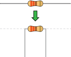
Getting Started with the A111 Pulsed Radar Sensor

$
0
0

Getting Started with the A111 Pulsed Radar Sensor a learn.sparkfun.com tutorial

Available online at: http://sfe.io/t1004

Introduction

Heads up! If you are looking for the hookup guide for the SparkX version of the A111, you can check out the retired tutorial: Using the A111 Pulsed Radar Sensor with a Raspberry Pi. However, the tutorial is outdated due to the SDK version used in the previous tutorial.

Does your project require high-precision, cutting-edge distance, speed, motion, and/or gesture sensing? We're not talking ultrasonic, or even infrared here, but 60GHz radar! Say hello to our tiny, pulsed radar friend the Acconeer A111!

SparkFun Pulsed Radar Breakout - A111

SparkFun Pulsed Radar Breakout - A111

SEN-15577
$59.95

The A111 is a single-chip solution for pulsed coherent radar (PCR) -- it comes complete with antennae and an SPI interface capable of speeds of up to 50MHz. Applications for PCR include distance-sensing, gesture, motion, and speed detection. The sensor can monitor one-or-more objects at distances of up to two meters.

Our breakout board for the A111 includes a 1.8V regulator, voltage-level translation, and it breaks out all pins of the pulsed radar sensor to both 0.1-inch and Raspberry Pi-friendly headers.

Required Materials

To use the A111 you'll need either an ARMv7 or an ARM Cortex-M4 -- the closed-source SDK currently only supports these architectures. This tutorial will explain how to use the radar sensor with a Raspberry Pi -- a platform based on an architecture supported by the A111's SDK.

The A111 Breakout includes a 20-pin, 2x10 female header, which should mate to Raspberry Pi's of any generation. If you'd rather manually wire the A111 to your Raspberry Pi and about 9 male-to-female wires should do the trick.

Raspberry Pi 3 B+ Starter Kit

Raspberry Pi 3 B+ Starter Kit

KIT-14644
$91.95
6
Jumper Wires Premium 12" M/F Pack of 10

Jumper Wires Premium 12" M/F Pack of 10

PRT-09385
$4.50
1
SparkFun Pulsed Radar Breakout - A111

SparkFun Pulsed Radar Breakout - A111

SEN-15577
$59.95

Optional Materials

You have several options when it comes to working with the Raspberry Pi. Most commonly, the Pi is used as a standalone computer, which requires a monitor, keyboard, and mouse (listed below). To save on costs, the Pi can also be used as a headless computer (without a monitor, keyboard, and mouse). This setup has a slightly more difficult learning curve, as you will need to use the command-line interface (CLI) from another computer.

Raspberry Pi LCD - 7" Touchscreen

Raspberry Pi LCD - 7" Touchscreen

LCD-13733
$64.95
39
SmartiPi Touch

SmartiPi Touch

PRT-14059
$24.95
8
Multimedia Wireless Keyboard

Multimedia Wireless Keyboard

WIG-14271
$29.95
3

Suggested Reading

If you aren’t familiar with the following concepts, we recommend checking out these tutorials before continuing. Using the Pi as a headless setup or with VNC can be useful when developing applications with the Pi.

Raspberry Pi SPI and I2C Tutorial

Learn how to use serial I2C and SPI buses on your Raspberry Pi using the wiringPi I/O library for C/C++ and spidev/smbus for Python.

Raspberry Pi 3 Starter Kit Hookup Guide

Guide for getting going with the Raspberry Pi 3 Model B and Raspberry Pi 3 Model B+ starter kit.

Headless Raspberry Pi Setup

Configure a Raspberry Pi without a keyboard, mouse, or monitor.

How to Use Remote Desktop on the Raspberry Pi with VNC

Use RealVNC to connect to your Raspberry Pi to control the graphical desktop remotely across the network.

Hardware Overview

Sensor and Crystal

The breakout board is populated with the A111 IC and an external 26MHz crystal oscillator. The IC comes with two antennae and uses mmWave radio to sense objects via radar pulses.

A1111 Populated on TopCrystal Oscillator Populated on Back
A111 Populated on TopCrystal Oscillator Populated on Back

2x13 Female Header

To keep the size of the board small, there is a 2x13 female header soldered on the board to easily mate with a Raspberry Pi's standard header.

Female Header Pins

This should only cover the part of the 2x20 male headers on the Pi.

A111 HAT Stacked on a Raspberry Pi

Additional Pins Broken Out

Just above the 26-Pin header, there are additional pins broken out for SPI, interrupt, enable, and power if you need access to the pins. The A111 IC requires an input voltage of 1.8V, so a voltage regulator is populated on the back. Additionally, the I/O logic level is 1.8V, so a logic converter is included to translate the signals.

A111 Additional Header Pins Broken OUt for SPI, Interrupt, Enable, and Power
Voltage Regulator    Logic Level Converter
Voltage RegulatorLogic Level Converter

Board Dimensions

The overall board size is 1.30in x 1.55in. There are two additional mounting holes spaced 0.10 inches away from the edge of the board.

Board Dimension

Hardware Assembly

The A111 Pulsed Radar Breakout is designed to sit directly on top of a Raspberry Pi. Again, it doesn't span all 40 (2x20) pins of a Raspberry Pi B+ (or later), but the 26-pin — 2x13 — header should be compatible with any Pi.

Connect the shield to a Raspberry Pi ensuring that the "Pi Display" text on the breakout matches up with the display header on your Pi. The sensor should be facing up after plugging it in.

A111 HAT Stacked on a Raspberry Pi

A111 Breakout plugged into a Raspberry Pi.

Or, if you'd like to manually wire the breakout up to a Pi, here is the pin-out we'll use through the rest of this tutorial:

Breakout PinRaspberry Pi Pin NameRasPi Hardware Pin Number
CSSPI0 CS024
SCLKSPI0 SCLK23
MISOSPI0 MISO21
MOSISPI0 MOSI19
INTGPIO2522
ENGPIO2713
GNDGND6, 14, 20, etc.
VIN5V2, 4

Configure Your Pi

Raspbian and SPI

This tutorial assumes you've already set up a Raspberry Pi with Raspbian. For help installing the Debian-based OS on your Pi, check out the docs on Raspberrypi.org. Or -- better yet! -- check out our Headless Raspberry Pi Setup tutorial.

You'll also need to enable SPI on your Pi. For help with that, check out our SPI on Pi tutorial.

We are going to assume you already have a Raspberry Pi up and running with Raspbian. We'll also assume that it is connected to the Internet. If not, check out our starter kits and tutorials on setting up a Raspberry Pi.

Raspberry Pi 3 Starter Kit Hookup Guide

April 11, 2016

Guide for getting going with the Raspberry Pi 3 Model B and Raspberry Pi 3 Model B+ starter kit.

Make sure to update the image so that we have the latest distribution. Enter the following commands in the command line individually to update your image.

language:bash
sudo apt-get update
sudo apt-get dist-upgrade
Note: sudo stands for "Super User Do", it is a way to give you superuser powers from the command line. Be careful whenever using sudo.

User Configuration Settings

Once you are set up, I highly recommend changing your default login and password: (username: pi, password: raspberry). The Raspberry Pi Configuration tool is a quick way to change your password as well as setup the network, language, keyboard, etc. There are two methods to adjust the settings. You can use the GUI by heading to the Pi Start Menu>Preferences>Raspberry Pi Configuration>Interfaces. For the old school heads, you can also use the raspi-config tool by typing the following command using the command line and then go through the menus to update your information.

language:bash
sudo raspi-config

You'll want to enable the SPI pins using the tool to read sensor with SPI. If you are using hte GUI, simple select Enable and click on the OK button. If you are using the raspi-config, follow the prompts to finish setting up the SPI. For more information, check out our tutorial to set up the SPI pins on a Pi.

Enabling SPI via Desktop GUIEnabling I2C on a Pi
Enabling SPI via Desktop GUIraspi-config tool for SPI in the Terminal

You'll need to restart your Pi for the changes to take effect.

Get the SDK

The software development kit (SDK) for the A111 is, unfortunately, locked behind a closed source blob that currently only supports Cortex-M4 and ARMv7 platforms. However the folks over at Acconeer have agreed to host the latest version of their SDK with our example code within SparkFun's Pulsed Radar Example Code repository on Github. To download the SDK from Acconeer, visit Acconeer's "Developer" page on your Raspberry Pi's browser.

You'll need an account in order to have access to the files. Click on the link at the bottom of the page to create one or log in. Or click on the shortcuts below.

Once you are logged in, the "SW Download" tab will include additional links to download the SDK. Scroll down the webpage to the section for the XC111. Acconeer is constantly updating and improving the software. We used v1.8.6 of the software when writing this tutorial so the version may be different from the version that you download. Click on the Download button for v1.8.6.

alt text

Download the SDK from Acconeer.

Read through the license, agree, and click on the Download acconeer_rpi_xc111 button for the software. Depending on your browser, you may need to refresh the page and repeat the directions before the button is active.

Once downloaded, head to directory where you downloaded the ZIP. You can use the GUI or you can use the terminal to unzip the SDK using the following commands (included are commands to install unzip). Just make sure to update the file name with the version that you downloaded. Assuming that you are in the Downloads folder, you will be using the following command in the Terminal.

language:bash
unzip acconeer_rpi_xc111_v1_8_6.zip -d a111

Then cd to the "a111/rpi_xc111/..." directory to prepare to build the example software. Depending on the version that you downloaded, the path might be slightly different. Make sure to use the ls to verify the contents of the unzipped a111 folder if you have issues navigating through the directory.

SDK Overview

The A111 SDK includes source code, archived libraries, include files, and documentation for using the A111 pulsed radar sensor. Here's a quick overview of what's included with the SDK:

  • doc— Doxygen-generated documentation for the A111 API and source code.
  • include— Header and API files which describe how to interact with the pre-compiled A111 libraries.
  • lib— Pre-compiled A111 static archives. API for these files are provided in the "include" directory.
  • out— Compiled board and example object and executable files.
  • rule— Recursive Makefile rules for board and example files.
  • source— C source files for custom boards and example applications.
  • makefile— Top-level makefile. Recursively calls files in the "rule" directory to build example and board files.

Adding Custom Example and Board Files

The SparkFun A111 Breakout's default pins will not work with those of the SDK's examples. To build and run an example with this board, we have an example board definition, make scripts, and example applications. Click the button below to download these files from the GitHub repo. The code currently works for v1.8.6.

Once downloaded, head to the folder where you downloaded the example code and unzip the files. You can use the GUI to extract by right clicking and selecting Extract Here. Or you can use the following command if you are using a Terminal. Make sure to use the cd so that you are in the same folder as the ZIP file.

language:bash
unzip SparkFun_Pulsed_Radar_A111_Example_Code-master.zip -d SparFun_Pulsed_Radar_A111_Example_Code-master

Once extracted move the files provided from the ../SparkFun_Pulsed_Radar_A111_Example_Code-master/sparkfun-a111-source to ...a111/rpi_xc111. We recommend opening a separate window using the GUI to drag and drop the files into the file path. This will add the SparkFun examples into the respective paths. You'll get a window that pops up. Click the Overwrite button for each window that pops up to add the files into their respective folders.

Drag and Drop Files into Folder

Build and Run the Test Sketch

In the terminal, executing the make file — and it's recursive dependencies — should build all of the examples you may use with the A111. To build all board and example files, navigate to the SDK's top-level directory (in this case, it should be similar to ...Downloads/a111/rpi_xc111) where your makefile is located and type make in the terminal. You should see something similar to the output below.

Terminal Output usnig Make Command

Troubleshooting

If you have any trouble building the board and example files, ensure that you have gcc and make packages installed. (E.g. apt-get install make gcc)

Running the Example Applications

Once compiled you can run the example applications. Navigate to the .../out folder with the cd in the terminal window. You can run the example by clicking on the executable or typing the following command. We recommend typing the command in the terminal to view the data. A few of the applications will automatically close the window after taking sensor data if you choose to click on the executable.

language:bash
./sparkfun_detector_distance_basic

Once you type (or paste the command in the Terminal), hit Enter on your keyboard to execute the command.

Before Entering Command

This will run our modified distance-detector example application. For simplicity, it will show the distance of an object that is in front of the antennae.

Distance Example Running

By placing an object in front of the sensor, the distance should vary based on what the A111 can detect. The application will continue running in the terminal window until CTRL + C is pressed.

Hand in Front of A111 Sensor

Hand placed in front the A111 with the Pi remotely connected via VNC..

Running Other Examples

In addition to the distance detector basic, the SDK includes a few extra examples. To execute these files, run them from the out directory:

  • sparkfun_detector_motion— If there is an object moving in front of the sensor, it will output a true. Otherwise, the output is false.
  • sparkfun_detector_obstacle— Checks to see if there is an object in the way.
  • sparkfun_detector_service_iq— Advanced version of the envelope service, which includes phase information for very small variations in distance. The output will be in polar coordinates.
  • sparkfun_detector_power_bins— Demonstrates how to use A111 "power bins," which are still, kind of, a mystery to us...
  • sparkfun_distance_detector_peak— This application will begin by calculating raw peak-distances, with a maximum of ten reflections. The example will briefly estimate minimum and maximum threshold.

Make sure to read through the comments in the code (located in the source folder), datasheet, user guide, and associated documents from Acconeer for more information before writing your own custom code for the A111.

Resources and Going Further

Now that you've successfully got your A111 pulsed radar sensor up and running, it's time to incorporate it into your own project! For more information, check out the resources below:

Need some inspiration for your next project? Check out some of these related tutorials:

Getting Started with Walabot

See through walls, track objects, monitor breathing patterns, and more using the power of radio frequency with the Walabot! In this tutorial, we will explore Walabot’s features using the Software Demo Kit (SDK) on Windows and the Application Programming Interface (API) on Linux-based distributions for embedded projects.

Qwiic Kit for Raspberry Pi Hookup Guide

Get started with the CCS811, BME280, VCNL4040, and microOLED via I2C using the Qwiic system and Python on a Raspberry Pi! Take sensor readings from the enviroment and display them on the microOLED, serial terminal, or the cloud with Cayenne!

learn.sparkfun.com | CC BY-SA 3.0 | SparkFun Electronics | Niwot, Colorado
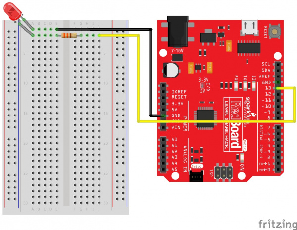
GPS Geo-Mapping at the Push of a Button

$
0
0

GPS Geo-Mapping at the Push of a Button a learn.sparkfun.com tutorial

Available online at: http://sfe.io/t904

Introduction

If you need an intermediate GPS project to tickle your fancy, we've got one ready to go. In a previous tutorial, we slapped some boards together to see our GPS locations on an OLED Screen. It was a great learning experience, but we need something more. Today we'll do some more good 'ol board slappin', and we'll save multiple coordinates in a KML file and take over the world! Okay, not take over, but we can easily see collections of coordinates all over the world with Google Earth.

alt text

Required Materials

Suggested Reading

If you aren't familiar with the Qwiic system, we recommend reading here for an overview.

Qwiic Connect System

We would also recommend taking a look at the following tutorials if you aren't familiar with them.

How to Solder: Through-Hole Soldering

This tutorial covers everything you need to know about through-hole soldering.

Serial Peripheral Interface (SPI)

SPI is commonly used to connect microcontrollers to peripherals such as sensors, shift registers, and SD cards.

I2C

An introduction to I2C, one of the main embedded communications protocols in use today.

MicroSD Shield and SD Breakout Hookup Guide

Adding external storage in the form of an SD or microSD card can be a great addition to any project. Learn how in this hookup guide for the microSD shield and SD breakout boards.

Qwiic Micro OLED Hookup Guide

Get started displaying things with the Qwiic Micro OLED.

RedBoard Turbo Hookup Guide

An introduction to the RedBoard Turbo. Level up your Arduino-skills with the powerful SAMD21 ARM Cortex M0+ processor!

Adding More SERCOM Ports for SAMD Boards

How to setup extra SPI, UART, and I2C serial ports on a SAMD-based boards.

SparkFun GPS Breakout (ZOE-M8Q and SAM-M8Q) Hookup Guide

The SparkFun ZOE-M8Q and SAM-M8Q are two similarly powerful GPS units but with different project applications. We'll compare both chips before getting each up and running.

Hardware Overview

If you followed along with the last GPS tutorial, you'll have an idea of where we're going. However, since we're packing more stuff into a small module, we'll need more power. Unfortunately, the 5 libraries we'll be using pushes the original RedBoard to its limits. So to make up the gap, we'll use the SAMD21. Specifically speaking, the SparkFun RedBoard Turbo!

RedBoard Turbo

The Turbo is a relatively new development board, sporting the versatile ATSAMD21G18 ARM Cortex-M0+ microcontroller. It's also carrying an RTC Crystal, WS2812 addressable RGB LED, and a LiPo battery connector with charging capabilities. It's almost TOO powerful for our purposes, but it conveniently has everything we need.

SparkFun RedBoard Turbo - SAMD21 Development Board

SparkFun RedBoard Turbo - SAMD21 Development Board

DEV-14812
$24.95
3

MicroSD Shield

The microSD shield is an Arduino Uno layout compatible memory shield. We'll interact with the microSD shield using the SPI bus through the shield's on board hex converter. Quick note, since the microSD shield is an older component than the Turbo there are some communication bugs, but we'll get to that a little later.

SparkFun microSD Shield

SparkFun microSD Shield

DEV-12761
$14.95
9

SAM-M8Q Chip Antenna GPS Breakout and Qwiic Micro OLED

It's worth mentioning once more the components carried across from the last tutorial. The SAM-M8Q Chip Antenna GPS provides simple and powerful GPS capabilities from Ublox's GPS systems. Those coordinates are then displayed to the user on the easy to wire, and no solder required, Qwiic Micro OLED screen.

SparkFun GPS Breakout - Chip Antenna, SAM-M8Q (Qwiic)

SparkFun GPS Breakout - Chip Antenna, SAM-M8Q (Qwiic)

GPS-15210
$39.95
2
SparkFun Micro OLED Breakout (Qwiic)

SparkFun Micro OLED Breakout (Qwiic)

LCD-14532
$16.95
3

Hardware Hookup

This part of the build will require some assembly (but that's what we're all really here for anyway). Since most of our components carry over from the simple push button GPS tracker tutorial, we only have a few additional parts to assemble. Now, if you're fresh to the GPS tracker projects you don't have to worry. We'll run through all of it again anyway.

Assembly

Push Button Wiring

Our push button will be rather straightforward. The table below shows the connections between the button and our Turbo via the microSD shield.

push button terminal hookup
Button PinRedBoard Pin
+5V
-GND
C1GND
NO1Digital Pin 2

These pins will connect to the Turbo pins (via the microSD shield PTH pins) as shown in the fritzing diagram above

MicroSD Shield

The first step would be to solder our break away headers to the pins aligning with the Redboard Turbo female headers. We also need to solder the 2x3 Female ISP connector to the bottom of the microSD shield. We'll use that ISP header for a modification needed for communication.

I mentioned earlier that there was a special note for communication between the Turbo and our microSD shield. The best explanation currently is there is a naming difference in libraries and the SERCOM tools used on the Turbo. We can easily circumvent the issue by hardwiring our Digital Pins (13 -11) to the ISP header found on all our Redboards.

microSD communication soldering

I discovered this issue when I was running a simple datalogger sketch and I kept getting a false return from the SD.begin() call. After making these hotwiring corrections, I got correct functionality.

Once we're done with the headers, we can move on to connecting our pushbutton. Following the table mentioned earlier, we need to solder our wires to the microSD shield. There are PTH holes alongside all the header holes to solder to. We're looking for these specific pins:

pushbutton pins
Button PinmicroSD Shield Pin
+5V
-GND
C1GND
NO1Digital Pin 2

Reference Diagrams

Hookup of Button to Shield

Hookup of Turbo, GPS, and Display

Optional Assembly

Aluminum Case

We do have an aluminum case added to the required materials list. While it is optional, it provides a sturdy case for practical application purposes. If you purchase the case then you'll have to make extra modifications. We'll need to drill screw holes and protuding areas for our OLED screen and GPS chip antenna.

Full assembly with aluminum case

Software Setup

Note: This code/library has been written and tested on Arduino IDE version 1.8.9. Otherwise, make sure you are using the latest stable version of the Arduino IDE on your desktop.

If this is your first time using Arduino, please review our tutorial on installing the Arduino IDE. If you have not previously installed an Arduino library, please check out our installation guide.

Component Libraries

First let's start with the two libraries for our Qwiic Micro OLED Breakout and SAM-M8Q Chip Antenna GPS Module.

Add these libraries using the Include Library option under the Arduino IDE option "Sketch".

How to add a .zip library in Arduino

Turbo Specialties

The Turbo does require some extras before we can program. Those are all done through the SAMD Arduino Libraries. Open Tools ->Board: "" ->Boards Manager... and find the following:

Boards Manager with SAMD
Arduino SAMD21 board files are needed, version 1.6.21 specifically

After the main Arduino board files are installed, we'll need the Sparkfun specific boards. For those we'll need to copy and paste the following in our Arduino "Additional Boards Manager URLs" preferences. Copy and paste:

https://raw.githubusercontent.com/sparkfun/Arduino_Boards/master/IDE_Board_Manager/package_sparkfun_index.json

Boards Manager
We want Sparkfun SAMD21 board files of version 1.6.1 (or newest available)

If you need reminders for what you're looking for later down the road, the code in the next section will have all required software components listed in the comments.

Google Earth and KML

Off the bat, if you need to download Google Earth. See you in a minute, no worries.

With that out of the way, KML is starkly different from the Arduino C or MicroPython we usually see here. It’s very similar to HTML used for websites. If you’re not familiar with the Hyper Text Markup Language, don’t worry because I’ll give you a rough (and I mean rough) overview of what we’re trying to achieve with it.

HTML

HTML mostly is a file with text (or images, or videos, or whatever black magic websites use nowadays) that is formatted using sectioning tags. Tags act like boxes, what’s in a box is owned by the box.

For example, in our code, we’ll see a tag called Placemark. In Google Earth, we will see our placemarks as yellow pins on the globe. If we save a placemark as follows:

language:xml
<placemark>
    <Point>
        <coordinates> 12.345678, 123.456789 </coordinates>
    </Point>
</placemark>

Then we’ve made a box called placemark with the GPS values inside. When Google Earth reads this a yellow pin will be placed on that exact coordinate. There are many more useful tags and tools for KML files. If you want to dive deeper, please feel free to visit the Google Developers page for KML. All of that is, in essence, what we’re trying to achieve.

Example Code

The code below is nothing fancy and doesn't have clever algorithms. There are many places within that can be improved for performance and efficiency. My hope was to allow a novice programmer to read and understand the big picture of what we're trying to do. From there improvements can and should be made!

Feel free to download the code from the GitHub location, or by clicking on the button below:

Alternatively, you can copy and paste the code from here:

language:c
/******************************************************************************
Google Earth KML GPS Position Logger v1.6
brandon.williams@sparkfun.com
May 6, 2019

The user will press a momentary button to log a GPS location into a KML file, 
a file that's stored on a microSD card in the microSD shield. If the user holds 
the button for 5 seconds, the program will effectively "end" with an infinite 
while loop after safely closing the file. The user can then remove the memory 
card to retrive the file and open using Google Earth.

** Significant changes and improvements can be made, please enjoy mod-ing! **

Resources:
SFE MicroOLED library: SFE_MicroOLED.h
SFE Ublox GPS library: http://librarymanager/All#SparkFun_Ublox_GPS 
Arduino SD required libraries: SPI.h & SD.h

Download Google Earth: https://www.google.com/earth/versions/

Development environment specifics:
Arduino IDE 1.8.9
Board Definition Packages:
  Arduino SAMD board Boards (32-bits ARM Cortex-M0+) 1.6.21
  SFE SAMD Boards 1.6.1
******************************************************************************/
//SD Shield libraries
#include <SPI.h>
#include <SD.h>
//OLED and Ublox libraries
#include <Wire.h>
#include <SFE_MicroOLED.h>
#include "SparkFun_Ublox_Arduino_Library.h"

#define PIN_RESET 9   //OLED
#define DC_JUMPER 1   //OLED

//create objects
SFE_UBLOX_GPS myGPS;
MicroOLED oled(PIN_RESET, DC_JUMPER);
File dataFile;

//declare golbal variables
const int buttonPin =  2;
const int chipSelect = 8; //Specific for SFE microSD shield, differs from Arduino SD libraries
int buttonState = 0;

void setup() {

  Wire.begin();

  //Classic SFE flame
  oled.begin();
  oled.clear(ALL);
  oled.display();
  delay(500);
  oled.clear(PAGE);
  oled.display();
  oled.setFontType(0);
  oled.setCursor(0,0);

  pinMode(buttonPin, INPUT_PULLUP);

  pinMode(chipSelect,OUTPUT);

  if(!SD.begin(chipSelect)){
    //If the SD card can't be initiallized/found just freeze with a loop
    oled.setCursor(0,0);
    oled.clear(PAGE);
    oled.print("SD, no work");
    oled.display();
    while(1);
  }
  oled.setCursor(0,0);
  oled.clear(PAGE);
      //Oh yea! don't forget the GPS shield needs to get it's first fix
  oled.print("Revving up the GPS unit, please wait");
  oled.display();
  delay(29000);
  oled.setCursor(0,0);
  oled.clear(PAGE);
  oled.print("Ready to start!");
  oled.display();
  oled.clear(PAGE);
  oled.display();

}

void loop() {
  double latitude;
  double longitude;

  // A little redundant, but simple fix to not add on to the file 
  SD.remove("sparkGPS.kml");

  dataFile = SD.open("sparkGPS.kml", FILE_WRITE);

  if (dataFile){
    //Write opening tags to file
    dataFile.println("<?xml version=\"1.0\" encoding=\"UTF-8\"?>");
    dataFile.println("<kml xmlns=\"http://www.opengis.net/kml/2.2\">");
    dataFile.println("<Document>");
    int state = 0;
    myGPS.begin();
    /* "Continous" (not quite) loop will run until user performs kill action.
     *  
     *  1. Button is pushed and released, then one coordinate 
     *  point will add to the file
     *  
     *  2. If the button is pushed and held, one last coordinate is saved. 
     *  Hold button till "Goodbye" appears to kill the loop. File is 
     *  closed and it is safe to remove power
     *  and remove the SD card.
     */
    while(state < 4){
      buttonState = digitalRead(buttonPin);
      state = 0;
      if(buttonState == LOW){
        oled.setCursor(0,0);
        oled.clear(PAGE);
        oled.print("button pressed");
        oled.display();
        delay(1000);
        oled.clear(PAGE);
        oled.display();

        state = 1;
        delay(900);
        if(buttonState == LOW){

          oled.setCursor(0,0);
          oled.clear(PAGE);
          oled.print("Getting Coordinates");
          oled.display();
          delay(1000);
          oled.clear(PAGE);
          oled.display();

          float latitude = myGPS.getLatitude();
          latitude = latitude / 10000000;

          float longitude = myGPS.getLongitude();
          longitude = longitude / 10000000;


          dataFile.println("\t<Placemark>");
          dataFile.println("\t\t<name>SFE GPS Extravaganza</name>");
          dataFile.println("\t\t<description>Where am I?</description>");
          dataFile.println("\t\t<Point>");
          dataFile.print("\t\t\t<coordinates>");
          dataFile.print(longitude,6);
          dataFile.print(",");
          dataFile.print(latitude,6);
          dataFile.print(",0");
          dataFile.println("</coordinates>");
          dataFile.println("\t\t</Point>");
          dataFile.println("\t</Placemark>");
          //Visual coordinates for the user to see
          oled.clear(PAGE);
          oled.setCursor(0,0);
          oled.print("Lat:");
          oled.print(latitude,6);
          oled.print("\nLong:");
          oled.print(longitude,6);
          oled.display();
          delay(1500);
          oled.clear(PAGE);
          oled.display();
        }
        buttonState = digitalRead(buttonPin);
        if(buttonState == LOW && state == 1){
          state = 2;
          delay(4000);
          buttonState = digitalRead(buttonPin);
          if(buttonState == LOW && state == 2){
            dataFile.println("</Document>");
            dataFile.println("</kml>");
            dataFile.close();
            oled.setCursor(0,0);
            oled.print("Goodbye");
            oled.display();
            delay(1000);
            oled.clear(PAGE);
            oled.display();
            //it is safe to remove power and remove data
            while(1); //"Ends program" more or less
          }

        }

      }
    }
  }
}

Upload the code using your Arduino IDE, and with any luck you'll start seeing coordinates across your OLED screen!

Resources and Going Further

GPS is a great technology for anyone to have in their back pocket. Thanks to the size of my enclosure, I literally have it in my back pocket. In all seriousness, this was a great project. It builds on good engineering principles and processes, teaches new technologies and platforms, as well as pushes ourselves out of our comfort zones just far enough. Thank you and I hope you can track your progress as much as I have!

Need more inspiration? Check out these other GPS related tutorials!

Copernicus II Hookup Guide

A guide for how to get started with the Copernicus II GPS module.

GPS Logger Shield Hookup Guide

How to assemble and hookup the SparkFun GPS Logger Shield. Never lose track of your Arduino again!

LS20031 5Hz (66 Channel) GPS Receiver Hookup Guide

In this tutorial, we will solder headers to the surface mount pads of the LS20031 GPS receiver and read the output using an Arduino!

Getting Started with the GeoFence

How to get started using the GeoFence GPS Boundary Widget and GeoFence Software.

learn.sparkfun.com | CC BY-SA 3.0 | SparkFun Electronics | Niwot, Colorado
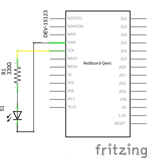
Fuse Breakout Board Hookup Guide

$
0
0

Fuse Breakout Board Hookup Guide a learn.sparkfun.com tutorial

Available online at: http://sfe.io/t966

Introduction

In this tutorial, we will explore two types of fuses, assemble the fuse breakout board, and add it to a circuit for protection!

SparkFun Fuse Breakout Board

SparkFun Fuse Breakout Board

BOB-15697
$1.95
SparkFun Fuse Breakout Kit

SparkFun Fuse Breakout Kit

KIT-15702
$4.95

Required Materials

To follow along with this tutorial, you will need a fuse with the breakout board! You may not need everything though depending on what you have. Add it to your cart, read through the guide, and adjust the cart as necessary. The minimum components needed for the glass ferrule fuse is included in the kit version. However, we suggest getting more than one glass fuse to replace when prototyping and testing.

SparkFun Fuse Breakout Kit

SparkFun Fuse Breakout Kit

KIT-15702
$4.95

If you are ordering the breakout board individually, you can pick a fuse that fits your project from our fuse category. Just make sure to get the necessary fuse clips and connectors for your needs.

Resettable Fuse PTC

Resettable Fuse PTC

COM-08357
$1.25
Fuse 5mm 250V 500mA

Fuse 5mm 250V 500mA

COM-10166
$0.95
Fuse 5mm 250V 200mA

Fuse 5mm 250V 200mA

COM-10165
$0.95
1
Fuse 5mm 125VAC 5A

Fuse 5mm 125VAC 5A

COM-09772
$0.50

Tools

You will need a soldering iron, solder, and general soldering accessories.

Soldering Iron - 60W (Adjustable Temperature)

Soldering Iron - 60W (Adjustable Temperature)

TOL-14456
$14.95
7
Solder Lead Free - 15-gram Tube

Solder Lead Free - 15-gram Tube

TOL-09163
$3.50
2
Pocket Screwdriver Set

Pocket Screwdriver Set

TOL-12891
$3.95
5

Suggested Reading

If you aren’t familiar with the following concepts, we recommend checking out these tutorials before continuing.

Connector Basics

Connectors are a major source of confusion for people just beginning electronics. The number of different options, terms, and names of connectors can make selecting one, or finding the one you need, daunting. This article will help you get a jump on the world of connectors.

What is a Circuit?

Every electrical project starts with a circuit. Don't know what a circuit is? We're here to help.

Electric Power

An overview of electric power, the rate of energy transfer. We'll talk definition of power, watts, equations, and power ratings. 1.21 gigawatts of tutorial fun!

Polarity

An introduction to polarity in electronic components. Discover what polarity is, which parts have it, and how to identify it.

How Does a Fuse Work?

Fuses are electrical components that help protect your project from overcurrent protection. Depending on the manufacturer and application, there are different current and voltage ratings. The rate at which the fuse blows out can also vary from slow-blow (a.k.a. time-delay), normal-blow, fast-blow, and ultra-fast. There are many types of fuses but we'll be focusing on the following.

  • glass ferrule fuse
  • resettable fuse (a.k.a positive temperature coefficient or PTC)

Glass Ferrule Fuses

A glass ferrule fuse is usually what comes to mind when you think of a fuse. They're pretty simple. If current exceeds the rating of the fuse, the small filament inside the fuse heats up and breaks (like a light bulb burning out). The circuit is then broken and hopefully your circuit is saved from molten destruction. The glass cartridges are useful for inspecting whether a fuse is blown but they operate a lower current faults compared to ceramic cartridges.

Glass Ferrule Fuse Blowing Out

Depending on the specification, you may notice the filament glow and blow out in fiery glory. Or you may notice the filament may just glow for a little bit and melt. In other cases, the filament may bend before disconnecting or melt into tiny, metal spheres (not as exciting).

Resettable Fuses (a.k.a. PTC)

A positive temperature coefficient (PTC) (a.k.a. multifuse, polyfuse, polyswitch, or thermistor) is a device that will increase in resistance as current flows through it. The PTC on the left is for through hole pads while the PTC on the right is for SMD.

PTH PTCSMD PTC
PTH PTCSMD PTC

PTCs are your friend! Beginners in electronics will often create shorts or accidentally hook things up backwards. These PTCs can be designed so that at a certain current flow (let's say a 250mA PTC with current protection of 500mA), the resistance increases dramatically, thus limiting the current flow. You can find some of these resettable fuse on certain motor boards and micrcontrollers that connect to a USB port as shown in the following images.

SMD PTC on Pi Servo HatCustom SMD PTC on Arduino UnoPTC Fuse on RedBoard Artemis
Resettable Fuse on the Servo Hat for a Raspberry PiCustom Resettable Fuse for the Arduino UnoResettable Fuse for the RedBoard Artemis

Basically, the PTC acts as a resettable fuse! You will want to place this device in series, before your voltage regulator. If your circuit draws more than 500mA (if you short power to ground for instance), the 250mA PTC will heat up and limit the current to 250mA. Once you remove the short, the current will drop back down, the PTC will cool off and the circuit will start operating normally again. It's a very cool little component that can save many designs from smoking.

Resettable Fuse included before voltage regulator

Resettable fuse included in design from the Beginning Embedded Electroics Tutorial Series.

The thermal images below of the PTC through hole fuse do a great job of showing what happens when a PTC is tripped. The thermal picture on the left shows a voltage regulating circuit in its normal state. The picture on the right shows a circuit when it is shorted. Notice how hot the PTC gets (213 °F!) as it limits the amount of damaging current going through the circuit. Major thanks to Joshua Weaver for the great thermal shots!

Voltage Regulator Operating Under Normal ConditionsPTC Fuse Tripped Preventing The Circuit from Being Damaged

Hardware Overview

VIN

On the left side, we have our input VIN. You can solder 2-pin screw terminal (5mm) on the input side (highlighted in yellow). Or you can solder a barrel jack for the input (highlighted in black) if you decide that you want to easily connect a wall adapter (with a center positive barrel jack) for a polarized connection.

VIN inputs highlighted

Keep in mind that the 5mm screw terminal is rated for more current compared to the barrel jack contacts. However, DC wall adapters sold from the catalog use barrel jacks to provide power. You can also solder wires directly to the breakout board as long as they are rated appropriately for the project.

Glass Fuse

There are two clips that will need to be soldered to the board if you are using a glass cartridge fuse. Make sure to solder the clips correctly.

Fuse Clip Locations

PTC Fuse

Through holes for a PTC fuse was added in case you decided to use a resettable PTC fuse. While the board was designed for a through hole PTC, you can solder still solder a SMD PTC fuse to the pads when prototyping. The component just may not fit as snug depending on the size of the SMD fuse.

Through Holes for PTC Fuse

VOUT

On the right side, we have our output VOUT. You can solder a 2-pin screw terminal (5mm) here.

VOUT

Mounting Holes

There are four mounting holes on the board if you decide to mount the board to a panel or in an enclosure. To ensure that the board size is reduced to a minimum, half of a mounting hole was included.

Part of Mounting Holes

Board Dimensions

The board is 0.50in x 2.56in. There are four semi-circle mounting holes should you decide to mount the board or place them side by side.

Board Dimension

Hardware Assembly

You'll need to solder your connectors and fuse clip to the breakout. You can solder the components in any order that you would like. If you have not soldered before, check out our tutorial below for tips!

How to Solder: Through-Hole Soldering

September 19, 2013

This tutorial covers everything you need to know about through-hole soldering.

Solder Input and Output Connectors

On the VIN side, you have two options. For those that are using this with wall adapters with a center positive barrel jack, you'll want to use it with a barrel jack connector. Otherwise, you can solder 5mm screw terminal on the VIN side.

Barrel5mm Screw Terminal for VIN
Barrel Jack for VIN5mm Screw Terminal for VIN

Once you have the input soldered, add the screw terminal to the VOUT side.

Solder the Screw Terminal on VOUT

Solder 5mm Fuse Clips

The next step is to solder the glass fuse's clips to the board. Insert the clips to the each side. You'll need to make sure that the clips are oriented correctly before tacking each leg down to the board. If you look closely at the silkscreen for each fuse clip, you will see one side of the square has a secondary line added. This is the side you should orient the curved bits towards. Once each leg is tacked down, solder the other leg down. The clips can get hot when soldering so you may want to tape it down against the board or use a small piece of cardboard to hold the clip against the board.

Fuse Clips Soldered

Click image for a closer view of the fuse clips!

Adding a Fuse to Your System

If you are using a glass fuse, you can now insert the glass cartridge into the clips. Should your fuse blow out, just grab a flat head screw driver and carefully pry it out.

Glass Cartridge Fuse Inserted

Otherwise, insert a barrel jack into VIN side or tighten the screws to hold down stripped wires between your power supply and load. Make sure to take note of the silkscreen for your voltage and ground wires.

Mounting

Part of the design includes semi-circle mounting holes. This is useful if you decide mount the board to a panel or enclosure. To mount, you will need to:

  • tighten some standoffs (or a screw and standoff)
    • ensure that there is room to slide the PCB(s) between the hardware
  • place the PCB between your standoffs to tighten
    • if you are using more than one fuse breakout, place the standoffs between the two PCBs before tightening
  • repeat for each standoff

alt text

Considerations When Choosing a Fuse

Choosing a fuse depends on your project. Here are a few considerations when placing a fuse after your power supply or battery.

Project Voltage & Current Requirements

You'll first want a fuse that is able to handle your load's voltage and current. The datasheet for the fuse should provide that information. Then measure the maximum power that the project is expected to pull from your power supply without damaging the circuit. If the project is outputting an excessive amount of heat for a period of time, you may want to take that into account. With the measurements, you'll want to decide the current at which the fuse blows or trips. This value is usually at or below the trip current and within the power suppliy's amperage (i.e. if you want the fuse to trip when part of your load pulls 1A with a 20A high current power supply). Projects that have brief spikes in current (such as robots using motors) would need a slow blow (a.k.a. time-delay). Other projects may require the fuse to be blown out immediately would require a fast or ultrafast. We'll assume that they will be used at room temperature.

Glass Ferrule Fuse or PTC

For high current power supplies, you may want to consider using a glass ferrule fuses that disconnects and blow out in your project. For lower current power supplies, you may want to consider using a resettable fuse. Just keep in mind that the resettable fuses can get hot when tripped and can still leak current to your load.

Stress Testing

Once you have decided on a fuse to use for your prototyping needs, make sure to test it out! Yes, that means sacrificing your glass ferrule fuse but you'll want to ensure that the component works as expected when your circuit starts having a mind of its own.

Example

High Current Power Supplies

The inspiration for designing this board came after reading Hackaday's article: The Engineering Case for Fusing Your LED Strips. For power supplies with high current output, they'll simply keep pouring current to your load. This can damage your circuit and present quite a fire hazard. Placing the fuse close to your power suppliy's output can protect your circuit in case anything happens down the line. In this case, we'd want the fuse to blow out and disconnect the power to the rest of the LEDs. If you are using multiple LED strips off of one high current power supply, you would simply divide the current for each LED strip section.

Fuse Placed Between Large Power Supply and the Rest of the System

Low Current Power Supplies

If you decide to use a resettable PTC fuse with low current power supply, you could place it right after your input voltage. Below is an example schematic with the PTC placed between the wall adapter and voltage regulator. Placing a PTC fuse with the breakout board when prototyping is useful if you need to quickly test the setup before including it in the final design.

PTC Fuse Before Voltage Regulator

PTC fuse used in the design of the Breadboard Power Supply Kit.

Below is an example of placing a PTC fuse between the USB connector and microcontroller.

PTC fuse Before Microcontroller

PTC fuse used in the design of the RedBoard Qwiic

Resources and Going Further

Now that you've successfully got your fuse breakout board up and running, it's time to incorporate it into your own project! For more information, check out the following links.

Need some inspiration? Check out some of these other related tutorials:

Benchtop Power Board Kit Hookup Guide

November 3, 2014

Need more power? This Benchtop ATX Power Supply Kit should help give you the boost you need to power those energy hungry projects.

Electric Power

An overview of electric power, the rate of energy transfer. We'll talk definition of power, watts, equations, and power ratings. 1.21 gigawatts of tutorial fun!

Sunny Buddy Solar Charger V13 Hookup Guide

How to hookup the Sunny Buddy: a solar-powered, MPPT (peak-power tracking), LiPo battery charger.

FemtoBuck Constant Current LED Driver Hookup Guide V12

The FemtoBuck board is a high-efficiency, single-channel constant-current LED driver.

LilyPad Basics: Powering Your Project

Learn the options for powering your LilyPad projects, LiPo battery safety and care, and how to calculate and consider power constraints on your projects.

Or check out the following blog posts for ideas:


learn.sparkfun.com | CC BY-SA 3.0 | SparkFun Electronics | Niwot, Colorado
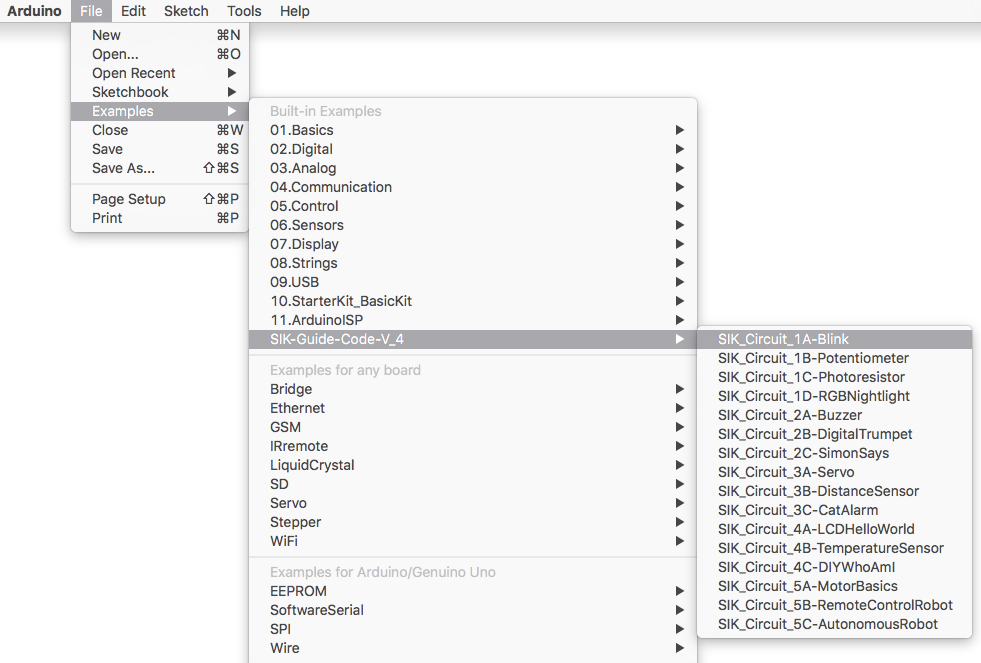
Viewing all 1123 articles
Browse latest View live