Introduction
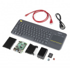
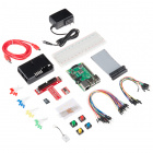
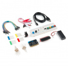
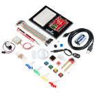
The SparkFun Tinker Kit is your starter tool kit for beginning with embedded electronics, robotics and citizen science using the SparkFun RedBoard Qwiic without breaking the bank. This guide contains all the information you will need to explore the 11 circuits of the Tinker Kit. At the center of this guide is one core philosophy -- that anyone can (and should) play around with cutting-edge electronics in a fun and playful way.
In stock
KIT-18577
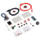
The SparkFun Tinker Kit (STK) is a great way to get started with programming and hardware interaction with the Arduino progra…
When you're done with this guide, you'll have the know-how to start creating your own projects and experiments. From building robots and game controllers to data logging, the world will be your oyster. Now enough talking -- let's start tinkering!
Open Source!
At SparkFun, our engineers and educators have been improving this kit and coming up with new experiments for a long time now. We would like to give attribution to Oomlout, since we originally started working off their Arduino Kit material many years ago. The Oomlut version is licensed under the Creative Commons Attribution Share-Alike 3.0 Unported License.
The SparkFun Tinker Kit is licensed under the Creative Commons Attribution Share-Alike 4.0 International License.
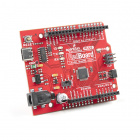
The SparkFun RedBoard Qwiic
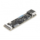
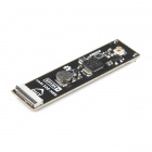
The SparkFun RedBoard Qwiic is your development platform. At its roots, the RedBoard is essentially a small, portable computer also known as a microcontroller. You can program it to accept inputs such as the push of a button or a reading from a light sensor and interpret that information to control various outputs like blinking a light like an LED or spinning an electric motor. That’s where the term “physical computing” comes in; this board can take the world of electronics and relate it to the physical world in a real and tangible way.
The SparkFun RedBoard Qwiic is one of a multitude of development boards based on the ATmega328 microprocessor. It has 14 digital input/output pins (six of which can be pulse-width modulation outputs; also referred to as PWM), six analog inputs, a 16MHz crystal oscillator, a USB connection, a power jack, a reset button and a Qwiic connector for connecting other Qwiic devices. You’ll learn more about each of these features as you progress through this guide.
Check out the guide below to learn more about the SparkFun RedBoard Qwiic.
RedBoard Qwiic Hookup Guide
This tutorial covers the basic functionality of the RedBoard Qwiic. This tutorial also covers how to get started blinking an LED and using the Qwiic system.
If you'd like to learn more about the Qwiic System, we recommend reading here for an overview:
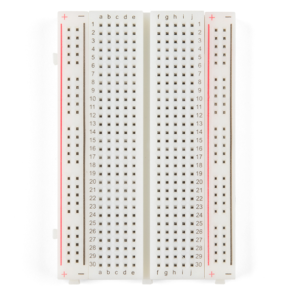
Understanding Breadboards
A breadboard is a circuit building platform that allows you to connect multiple components without using a soldering iron.
All experiments in this guide use the included breadboard so if you have never seen or used a breadboard before, we highly recommended you read the guide below that explains the breadboard's anatomy and how to use one.
How to Use a Breadboard
Welcome to the wonderful world of breadboards. Here we will learn what a breadboard is and how to use one to build your very first circuit.
Installing the Arduino IDE
The following steps provide a quick overview of getting started with the Arduino IDE and the RedBoard Qwiic USB drivers. For more detailed, step-by-step instructions on installing and using the Arduino IDE on your computer, please read through the tutorial below:
Installing Arduino IDE
A step-by-step guide to installing and testing the Arduino software on Windows, Mac, and Linux.
Download the Arduino IDE
In order to get your microcontroller up and running, you'll need to download the newest version of the Arduino IDE first (it's free and open source!).
This software, known as the Arduino IDE, allows you to program the board to do exactly what you want. It’s like a word processor for writing code. If you have not already, go ahead and open Arduino.
Optional: Download the Tinker Kit Code Examples
If you're looking to plan ahead for the circuits in this guide or just prefer to not copy and paste them into Arduino while following along, find them in the GitHub repository or click the button below to download a ZIP the Arduino examples:
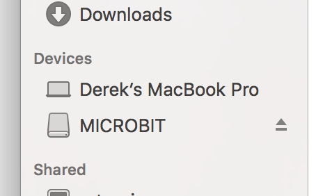
Unzip the download and either keep the Tinker Kit Code folder in your Downloads folder to open them as you go or you can move them to your Arduino sketchbook folder to open them in the Arduino IDE. If you're not sure where the sketchbook folder is, go to File > Preferences and look for the filepath titled "Sketchbook location". You can also use this option to change the sketchbook location if you prefer.
Having trouble seeing the detail in this screenshot? Click on it for a larger view.
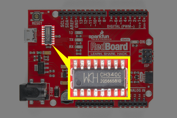
Install the CH340 USB Drivers
Heads up! Previous versions of the Tinker Kit featuring the SparkFun RedBoard Programmed with Arduino used the FTDI, which is a different USB-to-serial converter. Both function the same but require different drivers. If you look at the chip by the USB connector and you notice that it is the FTDI, make sure you follow the directions to
install the drivers for the FTDI.
If you are using the RedBoard Qwiic, you will need to install drivers for the CH340.
The drivers for the CH340C may be pre-installed on Windows, Mac, and Linux or may automatically install when the RedBoard Qwiic is connected to your computer. However, there are a wide range of operating systems and versions out there so we recommend installing the drivers to ensure that they work properly. Please go to How to Install CH340 Drivers
for specific instructions on how to install the CH340C drivers with your RedBoard Qwiic.
Connect the RedBoard to Your Computer
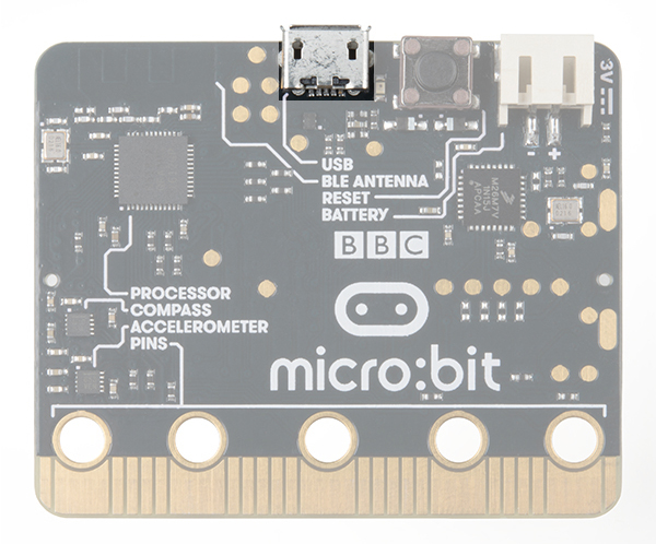
Connect the RedBoard Qwiic to one of your computer's USB inputs using the included micro-USB cable.
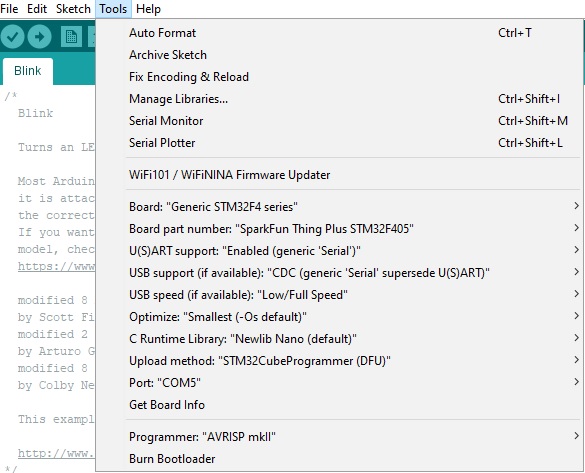
Select Your Board: Arduino Uno
Before we can start jumping into the experiments, there are a couple adjustments we need to make. This step is required to tell the Arduino IDE which of the many Arduino boards we have. Go up to the Tools menu then hover over Board and select Arduino Uno.
Note: In case you were wondering, your SparkFun RedBoard Qwiic and the Arduino Uno are interchangeable in the Arduino IDE but you won’t find the RedBoard Qwiic listed in Arduino by default.
Select a Serial Port
Next up we need to tell the Arduino IDE which of our computer's serial ports the microcontroller is connected to. For this, again go up to the Tools menu, then hover over Port and select your RedBoard's serial port. If you're not sure about which port is correct, open the Port menu without the RedBoard connected, take note of the ports available, connect the RedBoard and see which port appears. That new port is your RedBoard's port.
With that, you're ready to build your first circuit!
Circuit 1: Blink an LED
Light-Emitting Diodes, or LEDs (pronounced el-ee-dees), are small, powerful lights that are used in many different applications. You can find LEDs in just about any source of light nowadays, from the bulbs lighting your home to the tiny status lights flashing on your home electronics. Blinking an LED is the classic starting point for learning how to program embedded electronics. It's the "Hello, World!" of microcontrollers.
In this circuit, you'll write code that makes an LED flash on and off. This will teach you how to build a circuit, write a short program and upload that program to your RedBoard.
Parts Needed
This circuit requires the following parts:
- 1x Breadboard
- 1x SparkFun RedBoard Qwiic
- 1x Red LED
- 1x 330Ω Resistor
- 2x Jumper Wires
Didn't Get the Tinker Kit?
If you are conducting this experiment and didn't get the Tinker Kit, we suggest using these parts:
In stock
PRT-12002
This is your tried and true white solderless breadboard. It has 2 power buses, 10 columns, and 30 rows - a total of 400 tie i…
42In stock
DEV-15123
The SparkFun RedBoard Qwiic is an Arduino-compatible development board with a built in Qwiic connector, eliminating the need …
9In stock
COM-12062
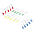
We all know that you can never get too many LEDs. Don't worry, we've got you covered. This is a pack of basic red, yellow, bl…
8In stock
PRT-11026
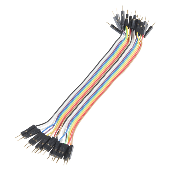
If you need to knock up a quick prototype there's nothing like having a pile of jumper wires to speed things up, and let's fa…
20In stock
PRT-14490
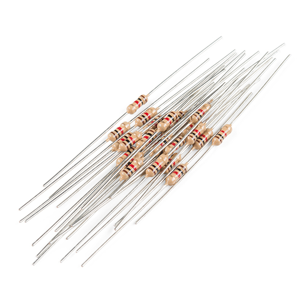
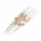
These are your run-of-the-mill 1/4 Watt, +/- 5% tolerance PTH resistors. Commonly used in breadboards and other prototyping a…
New Components and Concepts: Each circuit introduces new components or parts used in the circuit as well as a few new concepts that help you understand what your circuit and code does and why.
New Components
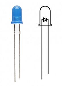
LED (Light Emitting Diode)
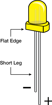
Light-Emitting Diodes (LEDs) are small lights made from a silicon diode. They come in different colors, brightnesses and sizes. LEDs have a positive (+) leg and a negative (-) leg, and they only let electricity flow through them in one direction. LEDs can also burn out if too much electricity flows through them, so you should always use a resistor to limit the current when you wire an LED into a circuit.
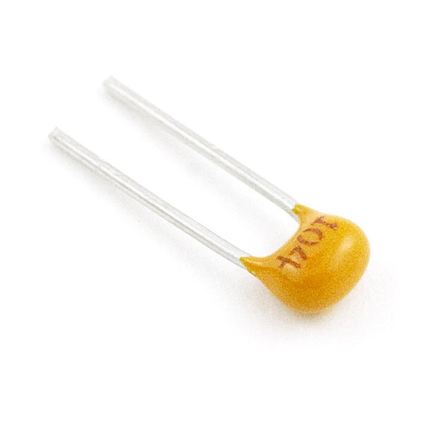
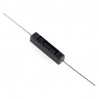
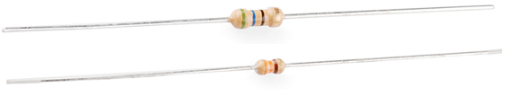
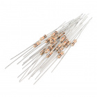
Resistors
Resistors create a resistance to limit the flow of electricity in a circuit. You can use them to protect sensitive components like LEDs. The strength of a resistor (measured in ohms) is marked on the body of the resistor using small colored bands. Each color stands for a number, which you can look up using a resistor chart.
New Concepts
Polarity
Many electronics components have polarity, meaning electricity only flows through them in one direction. Components like resistors do not have polarity; electricity flows through them in either direction. LEDs are polarized and only work when electricity flows through them in one direction.
Ohm's Law
Ohm's law describes the relationship between the three fundamental elements of electricity: voltage, resistance and current. The following equation represents their relationship:
Where
- V = Voltage in volts
- I = Current in amps
- R = Resistance in ohms (Ω)
Use this equation to calculate which resistor values are suitable to sufficiently limit the current flowing to the LED so that it does not get too hot and burn out.
Digital Output
When working with microcontrollers such as the RedBoard Qwiic, each has a variety of pins you can connect to electronic components. Knowing which pins perform which functions is important when building your circuit. This circuit uses what is known as a digital output. The RedBoard Qwiic has 14 pins that work as digital outputs. Digital pins only have two states: ON or OFF. These two states can also be thought of as HIGH/LOW or TRUE/FALSE, respectively. When an LED is connected to one of these pins, the pin can only perform two jobs: turning the LED on and turning the LED off. We'll explore the other pins and their functions in later circuits.
The 14 digital pins highlighted.
Hardware Hookup
Take some time familiarizing yourself with each of the components used in each circuit before assembling the parts.
| Polarized Components | Pay special attention to the component’s markings indicating how to place it on the breadboard. Polarized components can only be connected to a circuit in one direction. |
Pay close attention to the LED. It is polarized. The negative side of the LED is the short leg, marked with a flat edge.
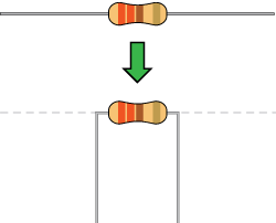
Components like resistors need their legs bent into 90° angles in order to correctly fit the breadboard sockets.
Ready to start hooking everything up? Check out the circuit diagram and hookup table below to see how everything connects.
Circuit Diagram
Circuit Diagrams: SparkFun uses a program called
Fritzing to draw the circuit diagrams you see throughout this guide. Fritzing allows us to create diagrams that make it easier for you to see how your circuit should be built.
Having a hard time seeing the circuit? Click on the image for a closer look.
Hookup Table
Hookup Tables: Many electronics beginners find it helps to have a coordinate system when building their circuits. For each circuit, you'll find a hookup table that lists the coordinates of each component and where it connects to the RedBoard, the breadboard, or both. The breadboard has a letter/number coordinate system, just like the game Battleship.
| Component | RedBoard Qwiic | Breadboard | Breadboard |
|---|
| LED | | A1 LED ( - ) | A2 LED ( + ) |
330Ω Resistor
(orange, orange, brown) | | E2 | F2 |
| Jumper Wire | GND | E1 | |
| Jumper Wire | Digital Pin 13 | J2 | |
In the table, polarized components are shown with a warning triangle and the whole row highlighted yellow. Open Your First Sketch
Open the Arduino IDE software on your computer if it's not already open. If you previously downloaded and moved the Tinker Kit Code into your Arduino sketchbook folder, open the Circuit 1 example by navigating to File > Sketchbook > SparkFun Tinker Kit Code > Circuit 1 Blink.
Alternatively, you can copy and paste the following code into a blank sketch in Arduino. Hit upload, and watch what happens!
language:cpp
/*
SparkFun Tinker Kit
Circuit 1: Blink an LED

Turns an LED connected to pin 13 on and off. Repeats forever.

This sketch was written by SparkFun Electronics, with lots of help from the Arduino community.
This code is completely free for any use.

View circuit diagram and instructions at: https://learn.sparkfun.com/tutorials/activity-guide-for-sparkfun-tinker-kit/
Download code at: https://github.com/sparkfun/SparkFun_Tinker_Kit_Code
*/

void setup() {

pinMode(13, OUTPUT);      // Set pin 13 to output

}


void loop() {

digitalWrite(13, HIGH);   // Turn on the LED

delay(2000);              // Wait for two seconds

digitalWrite(13, LOW);    // Turn off the LED

delay(2000);              // Wait for two seconds

}
What You Should See
The LED will turn on for two seconds then off for two seconds repeatedly. If it doesn't, make sure you have assembled the circuit correctly and verified and uploaded the code to your board, or see the Troubleshooting tips at the end of this section.
Program Overview
- Turn the LED on by sending power to Pin 13.
- Wait 2 seconds (2000 milliseconds).
- Turn the LED off by cutting power to Pin 13.
- Wait 2 seconds (2000 milliseconds).
- Repeat.
One of the best ways to understand the code you just uploaded is to change something and see how it affects the behavior of your circuit. For this first circuit, try changing the number found in these lines of code:
language:c
`delay(2000);`
What happens if you change both to 100? What happens if you change both to 5000? What happens if you change just one delay and not the other?
Onboard LED PIN 13: You may have noticed a second, smaller LED blinking in unison with the LED in your breadboard circuit. This is known as the onboard LED, and you can find one on almost any Arduino or Arduino-compatible board including the RedBoard. In most cases, this LED is connected to
digital pin 13 (D13), which is the same pin used in this circuit. This LED is useful for troubleshooting, as you can always upload the Blink sketch to see if that LED lights up. If so, you know your board is functioning properly. If you do not want this LED to blink with other LEDs in your circuits, simply use any of the other 12 digital pins (D0-D12).
![]()
Code to Note
Code to Note: The sketches that accompany each circuit introduce new programming techniques and concepts as you progress through the guide. The Code to Note section highlights specific lines of code from the sketch and explains them in further detail.
| Code | Description |
|---|
Setup and Loop:
void setup(){code to run once}&void loop(){code to run forever} | Every Arduino program needs these two functions. Code that goes in between the curly brackets of setup() runs once, then the code in between the loop() curly brackets runs over and over until the RedBoard is reset or powered off. |
Input or Output?:
pinMode(13, OUTPUT); | Before you can use one of the digital pins, you need to tell the RedBoard whether it is an INPUT or OUTPUT. We use a built-in "function" called pinMode() to make pin 13 a digital output. You'll learn more about digital inputs in the digital trumpet circuit. |
Digital Output:
digitalWrite(13, HIGH); | When you're using a pin as an OUTPUT, you can command it to be HIGH (output 5 volts) or LOW (output 0 volts). |
Delay:
delay(time in milliseconds); | Causes the program to wait on this line of code for the amount of time in between the brackets. After the time has passed, the program will continue to the next line of code. |
Comments:
//This is a comment | Comments are a great way to leave notes in your code explaining why you wrote it the way you did. You'll find many comments in the examples that further explain what the code is doing and why. Comments can be single line using //, or they can be multi-line using /* */. |
Coding Challenges
Coding Challenges: The Coding Challenges section is where you can find suggestions for changes to the circuit or code that will make the circuit more challenging. If you feel underwhelmed by the tasks in each circuit, visit the Coding Challenges section to push yourself to the next level.
| Challenge | Description |
|---|
| Persistence of Vision | Computer screens, movies and the lights in your house all flicker so quickly that they appear to be on all of the time but are actually blinking faster than the human eye can detect. See how much you can decrease the delay time in your program before the light appears to be on all the time but is still blinking. |
| Morse Code | Try changing the delays and adding more digitalWrite() commands to make your program blink a message in Morse code. |
Troubleshooting
Troubleshooting: Last, each circuit has a Troubleshooting section with helpful tips and tricks to aid you in any problems you encounter along the way.
| Problem | Solution |
|---|
| I get an error when uploading my code | The most likely cause is that you have the wrong board selected in the Arduino IDE. Make sure you have selected Tools > Board > Arduino Uno. |
| I still get an error when uploading my code | If you're sure you have the correct Board selected but you still can't upload, check that you have selected the correct Serial Port. You can change this in Tools > Serial Port >your_serial_port. |
| Which Serial Port is the right one? | Depending on how many devices you have plugged into your computer, you may have several active Serial Ports. Make sure you are selecting the correct one. A simple way to determine this is to look at your list of Serial Ports. Unplug your RedBoard from your computer. Look at the list again. Whichever Serial Port has disappeared from the list is the one you want to select once you plug your board back in to your computer. |
| My code uploads, but my LED won’t turn on | LEDs will only work in one direction. Try taking it out of your breadboard, turning it 180 degrees, and reinserting it. |
| Still not working? | Jumper wires unfortunately can go "bad" from getting bent too much. The copper wire inside can break, leaving an open connection in your circuit. If you are certain that your circuit is wired correctly and that your code is error-free and uploaded but you are still encountering issues, try replacing one or more of the jumper wires for the component that is not working. |
Circuit 2: Potentiometer
Potentiometers (also known as “pots” or “knobs”) are one of the more basic inputs for electronics devices. By tracking the position of the knob with your RedBoard, you can make volume controls, speed controls, angle sensors and a ton of other useful inputs for your projects. In this circuit, you'll use a potentiometer as an input device to control the speed at which your LED blinks.
Parts Needed
You will need the following parts:
- 1x Breadboard
- 1x SparkFun RedBoard
- 1x Red LED
- 1x 330Ω Resistor
- 7x Jumper Wires
- 1x Potentiometer
Didn't Get the Tinker Kit?
If you are conducting this experiment and didn't get the Tinker Kit, we suggest using these parts:
In stock
PRT-12002
This is your tried and true white solderless breadboard. It has 2 power buses, 10 columns, and 30 rows - a total of 400 tie i…
42In stock
DEV-15123
The SparkFun RedBoard Qwiic is an Arduino-compatible development board with a built in Qwiic connector, eliminating the need …
9In stock
COM-09806
This 10K trimmable potentiometer has a small knob built right in and it's breadboard friendly to boot!
6In stock
PRT-11026
If you need to knock up a quick prototype there's nothing like having a pile of jumper wires to speed things up, and let's fa…
20In stock
PRT-14490
These are your run-of-the-mill 1/4 Watt, +/- 5% tolerance PTH resistors. Commonly used in breadboards and other prototyping a…
In stock
COM-09590
LEDs - those blinky things. A must have for power indication, pin status, opto-electronic sensors, and fun blinky displays. …
New Components
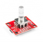
Potentiometer
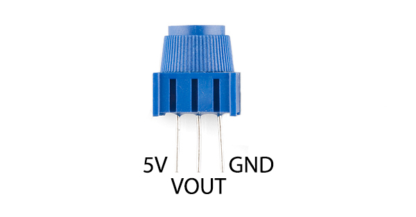
A potentiometer (trimpot for short) is a variable resistor. When powered with 5V, the middle pin outputs a voltage between 0V and 5V, depending on the position of the knob on the potentiometer. Internal to the trimpot is a single resistor and a wiper, which cuts the resistor in two and moves to adjust the ratio between both halves. Externally, there are usually three pins: two pins connect to each end of the resistor, while the third connects to the pot's wiper.
New Concepts
Analog vs. Digital
Understanding the difference between analog and digital is a fundamental concept in electronics.
We live in an analog world. There is an infinite number of colors to paint an object (even if the difference is indiscernible to our eye), an infinite number of tones we can hear, and an infinite number of smells we can smell. The common theme among all of these analog signals is their infinite possibilities.
Digital signals deal in the realm of the discrete or finite, meaning there is a limited set of values they can be. The LED from the previous circuit had only two states it could exist in, ON or OFF, when connected to a Digital Output.
Analog Inputs
So far, we've only dealt with outputs. The RedBoard also has inputs. Both inputs and outputs can be analog or digital. Based on our definition of analog and digital above, that means an analog input can sense a wide range of values versus a digital input, which can only sense two states.
You may have noticed some pins labeled Digital and some labeled Analog In on your RedBoard. There are only six pins that function as analog inputs labeled A0--A5.
The six analog pins highlighted.
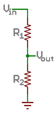
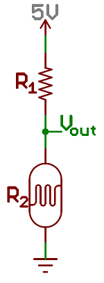
Voltage Divider
A voltage divider is a simple circuit that turns some voltage into a smaller voltage using two resistors. The following is a schematic of the voltage divider circuit. Schematics are a universally agreed upon set of symbols that engineers use to represent electric circuits.
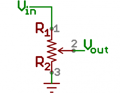
A potentiometer is a variable resistor that can be used to create an adjustable voltage divider.
A potentiometer schematic symbol where pins 1 and 3 are the resistor ends, and pin 2 connects to the wiper
If the outside pins connect to a voltage source (one to ground, the other to Vin), the output (Vout) at the middle pin will mimic a voltage divider. Turn the trimpot all the way in one direction, and the voltage may be zero; turned to the other side, the output voltage approaches the input. A wiper in the middle position means the output voltage will be half of the input.
Voltage dividers will be covered in more detail in the next circuit.
Hardware Hookup
The potentiometer has three legs. Pay close attention into which pins you're inserting it on the breadboard, as they will be hard to see once inserted.
Potentiometers are not polarized. You can attach either of the outside pins to 5V and the opposite to GND. However, the values you get out of the trimpot will change based on which pin is 5V and which is GND.
Ready to start hooking everything up? Check out the circuit diagram and hookup table below to see how everything is connected.
Circuit Diagram
Having a hard time seeing the circuit? Click on the image for a closer look.
Hookup Table
| Component | RedBoard | Breadboard | Breadboard | Breadboard |
|---|
| Jumper Wire | 5V | 5V Rail ( + ) | | |
| Jumper Wire | GND | GND Rail ( - ) | | |
| LED | | A1 LED ( - ) | A2 LED ( + ) | |
330Ω Resistor
(orange, orange, brown) | | E2 | F2 | |
| Jumper Wire | | E1 | GND Rail ( - ) | |
| Jumper Wire | Digital Pin 13 | J2 | | |
| Potentiometer | | B25 | B26 | B27 |
| Jumper Wire | Analog Pin 0 (A0) | E26 | | |
| Jumper Wire | | E25 | 5V Rail ( + ) | |
| Jumper Wire | | E27 | GND Rail ( - ) | |
In the table, polarized components are shown with a warning triangle and the whole row highlighted yellow. Open the Sketch
Open the sketch from your Arduino sketchbook or copy and paste the following code into the Arduino IDE. Hit upload, and see what happens!
language:c
/*
SparkFun Tinker Kit
Circuit 2: Potentiometer

Changes how fast an LED connected to pin 13 blinks, based on a potentiometer connected to pin A0

This sketch was written by SparkFun Electronics, with lots of help from the Arduino community.
This code is completely free for any use.

View circuit diagram and instructions at: https://learn.sparkfun.com/tutorials/activity-guide-for-sparkfun-tinker-kit/
Download code at: https://github.com/sparkfun/SparkFun_Tinker_Kit_Code
*/

int potPosition;       //this variable will hold a value based on the position of the potentiometer

void setup()
{
  Serial.begin(9600);       //start a serial connection with the computer

  pinMode(13, OUTPUT);      //set pin 13 as an output that can be set to HIGH or LOW
}

void loop()
{
  //read the position of the pot
  potPosition = analogRead(A0);    //set potPosition to a number between 0 and 1023 based on how far the knob is turned
  Serial.println(potPosition);     //print the value of potPosition in the serial monitor on the computer

  //change the LED blink speed based on the trimpot value
  digitalWrite(13, HIGH);           // Turn on the LED
  delay(potPosition);              // delay for as many miliseconds as potPosition (0-1023)

  digitalWrite(13, LOW);            // Turn off the LED
  delay(potPosition);              // delay for as many miliseconds as potPosition (0-1023)
}
What You Should See
Try adjusting the potentiometer's position and you should see the LED blink faster or slower in accordance with it. The delay between each flash will change based on the position of the knob. If it isn't working, make sure you have assembled the circuit correctly and verified and uploaded the code to your board, or see the Troubleshooting section.
Program Overview
- Read the position of the potentiometer (from 0 to 1023) and store it in the variable
potPosition. - Turn the LED on.
- Wait from 0 to 1023 milliseconds, based on the position of the knob and the value of
potPosition. - Turn the LED off.
- Wait from 0 to 1023 milliseconds, based on the position of the knob and the value of
potPosition. - Repeat.
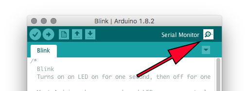
The Serial Monitor: The
Serial Monitor is one of the Arduino IDE's many great built-in tools. It can help you understand the values that your program is trying to work with, and it can be a powerful debugging tool when you run into issues where your code is not behaving the way you expected it to. This circuit introduces you to the Serial Monitor by showing you how to print the values from your potentiometer to it. To see these values, click the Serial Monitor button, found in the upper-right corner of the IDE in most recent versions. You can also select Tools > Serial Monitor from the menu.
![]()
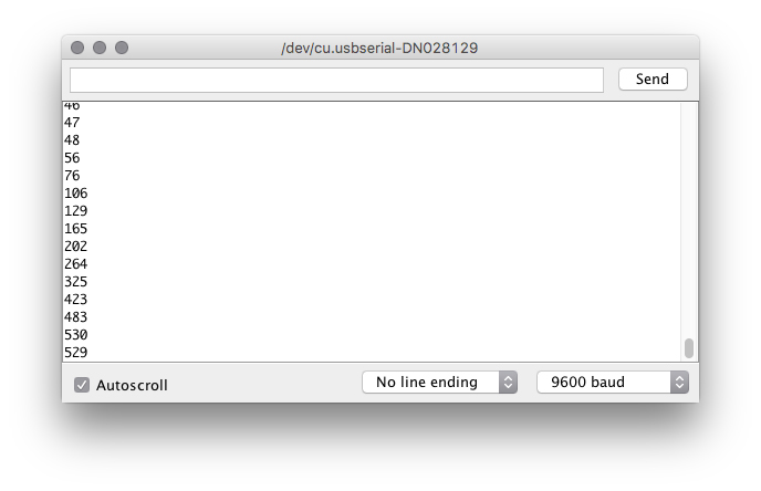
You should then see numeric values print out on the monitor. Turn the potentiometer, and you should see the values change as well as the delay between each print.
![]()
If you are having trouble seeing the values, ensure that you have selected
9600 baud in the dropdown menu and have auto scroll checked.
Code to Note
| Code | Description |
|---|
Integer Variables:
int potPosition; | A variable is a placeholder for values that may change in your code. You must introduce, or "declare" variables before you use them. Here we're declaring a variable called potPosition of type int (integer). We will cover more types of variables in later circuits. Don't forget that variable names are case-sensitive! |
Serial Begin:
Serial.begin(9600); | Serial commands can be used to send and receive data from your computer. This line of code tells the RedBoard that we want to "begin" that communication with the computer, the same way we would say "Hi" to initiate a conversation. Notice that the baud rate, 9600, is the same as the one we selected in the monitor. This is the speed at which the two devices communicate, and it must match on both sides. |
Analog Input:
potPosition = analogRead(A0); | We use the analogRead() function to read the value on an analog pin. analogRead() takes one parameter, the analog pin you want to use, A0 in this case, and returns a number between 0 (0 volts) and 1023 (5 volts), which is then assigned to the variable potPosition. |
Serial Print:
Serial.println(potPosition); | This is the line that actually prints the trimpot value to the monitor. It takes the variable potPosition and prints whatever value it equals at that moment in the loop(). The ln at the end of print tells the monitor to print a new line at the end of each value; otherwise the values would all run together on one line. Try removing the ln to see what happens. |
Coding Challenges
| Challenge | Description |
|---|
| Changing the Range | Try multiplying, dividing or adding to your sensor reading so that you can change the range of the delay in your code. For example, can you multiply the sensor reading so that the delay goes from 0–2046 instead of 0–1023? |
| Adding More LEDs | Add more LEDs to your circuit. Don't forget the current limiting resistor for each one. Try making multiple LEDs blink at different rates by changing the range of each using multiplication or division. |
Troubleshooting
| Problem | Solution |
|---|
| The potentiometer always reads as 0 or 1023 | Make sure that your 5V, A0 and GND pins are properly connected to the three pins on your potentiometer. It is easy to misalign a wire with the actual trimpot pin. |
| No values in Serial Monitor | Make sure that you have selected the correct baud rate, 9600. Also ensure that you are on the correct Serial Port. The same Serial Port you use when uploading code to your board is the same Serial Port you use to print values to the Serial Monitor. |
Circuit 3: Photoresistor
In the previous circuit, you got to use a potentiometer, which varies resistance based on the twisting of a knob. In this circuit you’ll be using a photoresistor, which changes resistance based on how much light the sensor receives. This circuit creates a simple night-light using the photoresistor that turns on when the room gets dark and turns off when it is bright.
Parts Needed
Gather the following parts required for this circuit:
- 1x Breadboard
- 1x SparkFun RedBoard Qwiic
- 7x Jumper Wires
- 1x Red LED
- 1x 330Ω Resistor
- 1x Photoresistor
- 1x 10kΩ Resistor
Didn't Get the Tinker Kit?
If you are conducting this experiment and didn't get the Tinker Kit, we suggest using these parts:
In stock
PRT-12002
This is your tried and true white solderless breadboard. It has 2 power buses, 10 columns, and 30 rows - a total of 400 tie i…
42In stock
DEV-15123
The SparkFun RedBoard Qwiic is an Arduino-compatible development board with a built in Qwiic connector, eliminating the need …
9In stock
COM-12062
We all know that you can never get too many LEDs. Don't worry, we've got you covered. This is a pack of basic red, yellow, bl…
8In stock
SEN-09088
This is a very small light sensor. A photocell changes (also called a [photodetector](http://en.wikipedia.org/wiki/Photodetec…
7In stock
PRT-11026
If you need to knock up a quick prototype there's nothing like having a pile of jumper wires to speed things up, and let's fa…
2028 available
PRT-14491
These are your run-of-the-mill 1/4 Watt, +/- 5% tolerance PTH resistors. Commonly used in breadboards and other prototyping a…
In stock
PRT-14490
These are your run-of-the-mill 1/4 Watt, +/- 5% tolerance PTH resistors. Commonly used in breadboards and other prototyping a…
New Components
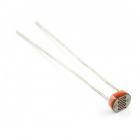
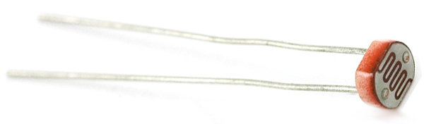
Photoresistor
Photoresistors, or photocells, are light-sensitive, variable resistors. As more light shines on the sensor’s head, the resistance between its two terminals decreases and vice versa. They’re an easy-to-use component in projects that require ambient-light sensing.
New Concepts
Analog to Digital Conversion
We covered the difference between analog and digital signals in the last experiment but you may be wondering how a digital thing like the RedBoard Qwiic can interpret analog signals. The answer to that is an Analog to Digital Converter (or ADC). The six analog inputs (A0--A5) we highlighted in the last circuit all use an ADC. These pins "sample" the analog signal and create a digital signal for the microcontroller to interpret. The "resolution" of this signal is based on the resolution of the ADC. In the case of the RedBoard, that resolution is 10-bit. With a 10-bit ADC, we get 2 ^ 10 = 1024 possible values, which is why the analog signal varies between 0 and 1023.
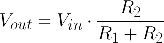
Voltage Divider Continued
Since the RedBoard can’t directly interpret resistance (rather, it reads voltage), we need to use a voltage divider to use our photoresistor, a part that doesn't output voltage. The resistance of the photoresistor changes as it gets darker or lighter which changes the amount of voltage that is read on the analog pin and "divides" the voltage, 5V in this case. That divided voltage is then read on the analog to digital converter.
Left: A regular voltage divider circuit. Vout will be a constant voltage. Right: A variable voltage divider circuit. Vout will fluctuate as the resistance of the photoresistor changes.
The voltage divider equation assumes that you know three values of the above circuit: the input voltage (Vin), and both resistor values (R1 and R2). Given those values, we can use this equation to find the output voltage (Vout):
If R1 is a constant value (the resistor) and R2 fluctuates (the photoresistor), the amount of voltage measured on the Vout pin changes.
Hardware Hookup
The photoresistor is not polarized. It can be inserted in either direction.
Ready to start hooking everything up? Check out the circuit diagram and hookup table below to see how everything is connected.
Circuit Diagram
Having a hard time seeing the circuit? Click on the image for a closer look.
Hookup Table
| Component | RedBoard | Breadboard | Breadboard |
|---|
| Jumper Wire | 5V | 5V Rail ( + ) | |
| Jumper Wire | GND | GND Rail ( - ) | |
| LED | | A1 LED ( - ) | A2 LED ( + ) |
330Ω Resistor
(orange, orange, brown) | | E2 | F2 |
| Jumper Wire | | E1 | GND Rail ( - ) |
| Jumper Wire | Digital Pin 13 | J2 | |
| Photoresistor | | A26 | B25 |
10kΩ Resistor
(brown, black, orange) | | C26 | D27 |
| Jumper Wire | Analog Pin 0 (A0) | E26 | |
| Jumper Wire | | E25 | 5V Rail ( + ) |
| Jumper Wire | | E27 | GND Rail ( - ) |
In the table, polarized components are shown with a warning triangle and the whole row highlighted yellow. Open the Sketch
Open the example code from your Arduino sketchbook or copy and paste the following code into the Arduino IDE. Hit upload, and see what happens!
language:cpp
/*
SparkFun Tinker Kit
Circuit 3: Photoresistor

Use a photoresistor to monitor how bright a room is, and turn an LED on when it gets dark.

This sketch was written by SparkFun Electronics, with lots of help from the Arduino community.
This code is completely free for any use.

View circuit diagram and instructions at: https://learn.sparkfun.com/tutorials/activity-guide-for-sparkfun-tinker-kit/
Download drawings and code at: https://github.com/sparkfun/SparkFun_Tinker_Kit_Code
*/

int photoresistor = 0;              //this variable will hold a value based on the position of the knob
int threshold = 750;                //if the photoresistor reading is below this value the light will turn on

void setup()
{
  Serial.begin(9600);               //start a serial connection with the computer

  pinMode(13, OUTPUT);              //set pin 13 as an output that can be set to HIGH or LOW
}

void loop()
{
  //read the position of the knob
  photoresistor = analogRead(A0);   //set photoresistor to a number between 0 and 1023 based on how far the knob is turned
  Serial.println(photoresistor);    //print the value of photoresistor in the serial monitor on the computer

  //if the photoresistor value is below the threshold turn the light on, otherwise turn it off
  if (photoresistor < threshold){
    digitalWrite(13, HIGH);         // Turn on the LED
  } else{
    digitalWrite(13, LOW);          // Turn off the LED
  }

  delay(100);                       //short delay to make the printout easier to read
}
What You Should See
The program stores the light level in a variable, photoresistor. Then, using an if/else statement, the program checks to see what it should do with the LED. If the variable is above the threshold (it’s bright), turn the LED off.
If the variable is below the threshold (it’s dark), turn the LED on. You now have just built your own night-light!
Open the Serial Monitor in Arduino. The value of the photoresistor should be printed every so often. When the photoresistor value drops below the threshold value set in the code, the LED should turn on (you can cover the photoresistor with your finger to make the value drop).
Note: If the room you are in is very bright or dark, you may have to change the value of the “threshold” variable in the code to make your night-light turn on and off. See the Troubleshooting section for instructions.
Program Overview
- Store the light level in the variable
photoresistor. - If the value of
photoresistor is above the threshold (it’s bright), turn the LED off. - If the value of
photoresistor is below the threshold (it’s dark), turn the LED on.
Code to Note
| Code | Description |
|---|
If/else Statements:
if(logic statement) {
code to be run if the logic statement is true}
else {
code to be run if the logic statement is false
} | The if/else statement lets your code react to the world by running one set of code when the logic statement in the round brackets is true and another set of code when the logic statement is false. For example, this sketch uses an if statement to turn the LED on when it is dark, and turn the LED off when it is light. |
Logical Operators:
(photoresistor < threshold) | Programmers use logic statements to translate things that happen in the real world into code. Logic statements use logical operators such as 'equal to' (==), 'greater than' (>), and 'less than' (<), to make comparisons. When the comparison is true (e.g., 4 < 5) then the logic statement is true. When the comparison is false (e.g., 5 < 4) then the logic statement is false. This example is asking whether the variable photoresistor is less than the variable threshold. |
Coding Challenges
| Challenge | Description |
|---|
| Response Pattern | Right now your if statement turns the LED on when it gets dark, but you can also use the light sensor like a no-touch button. Try using digitalWrite() and delay() to make the LED blink a pattern when the light level drops, then calibrate the threshold variable in the code so that the blink pattern triggers when you wave your hand over the sensor. |
| Replace 10KΩ Resistor with LED | Alter the circuit be replacing the 10KΩ resistor with an LED (the negative leg should connect to GND). Now what happens when you place your finger over the photoresistor? This is a great way to see Ohm's law in action by visualizing the change in resistance's affect on the current flowing through the LED. |
Troubleshooting
| Problem | Solution |
|---|
| The light never turns on or always stays on | Start the Serial Monitor in Arduino. Look at the value that the photoresistor is reading in a bright room (e.g., 915). Cover the photoresistor, or turn the lights off. Then look at the new value that the photoresistor is reading (e.g., 550). Set the threshold in between these two numbers (e.g., 700) so that the reading is above the threshold when the lights are on and below the threshold when the lights are off. |
| Nothing is printing in the Serial Monitor | Try unplugging your USB cable and plugging it back in. In the Arduino IDE, go to Tools > Port, and make sure that you select the right port. |
Circuit 4: RGB Night-Light
In this circuit, you'll take the night-light concept to the next level by adding an RGB LED, which is three differently colored Light-Emitting Diodes (LEDs) built into one component. RGB stands for Red, Green and Blue, and these three colors can be combined to create any color of the rainbow!
Parts Needed
You will need the following parts:
- 1x Breadboard
- 1x SparkFun RedBoard
- 12x Jumper Wires
- 1x LED - RGB Diffused Common Cathode
- 3x 330Ω Resistor
- 1x 10K Potentiometer
- 1x Photoresistor
- 1x 10kΩ Resistor
Didn't Get the Tinker Kit?
If you are conducting this experiment and didn't get the Tinker Kit, we suggest using these parts:
In stock
PRT-12002
This is your tried and true white solderless breadboard. It has 2 power buses, 10 columns, and 30 rows - a total of 400 tie i…
42In stock
DEV-15123
The SparkFun RedBoard Qwiic is an Arduino-compatible development board with a built in Qwiic connector, eliminating the need …
9In stock
COM-09806
This 10K trimmable potentiometer has a small knob built right in and it's breadboard friendly to boot!
6In stock
SEN-09088
This is a very small light sensor. A photocell changes (also called a [photodetector](http://en.wikipedia.org/wiki/Photodetec…
7In stock
COM-09264
Ever hear of a thing called RGB? Red, Green, Blue? How about an RGB LED? These 5mm units have four pins - Cathode is the long…
2In stock
PRT-11026
If you need to knock up a quick prototype there's nothing like having a pile of jumper wires to speed things up, and let's fa…
2028 available
PRT-14491
These are your run-of-the-mill 1/4 Watt, +/- 5% tolerance PTH resistors. Commonly used in breadboards and other prototyping a…
In stock
PRT-14490
These are your run-of-the-mill 1/4 Watt, +/- 5% tolerance PTH resistors. Commonly used in breadboards and other prototyping a…
New Components
RGB LED
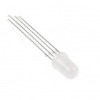
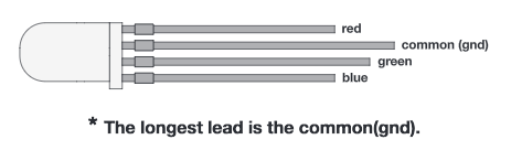
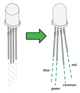
An RGB LED is actually three small LEDs --- one red, one green and one blue --- inside a normal LED housing. The RGB LED included in this kit has all the internal LEDs share the same ground wire, so there are four legs in total. To turn one color on, ensure ground is connected, then power one of the legs just as you would a regular LED. If you turn on more than one color at a time, you will see the colors start to blend together to form a new color.
New Concepts
Analog Output (Pulse-width Modulation)
You can use the digitalWrite() command to turn pins on the RedBoard on (5V) or off (0V), but what if you want to output 2.5V? The RedBoard doesn't have an Analog Output, but it is really good at switching some digital pins on and off fast enough to simulate an analog output. analogWrite() can output 2.5 volts by quickly switching a pin on and off so that the pin is only on 50 percent of the time (50% of 5V is 2.5V). By changing the percent of time that a pin is on, from 0 percent (always off) to 100 percent (always on), analogWrite() can output any voltage between 0 and 5V. This is known as pulse-width modulation (or PWM). By using PWM, you can create many different colors with the RGB LED.
Digital (PWM~): Only a few of the pins on the RedBoard have the circuitry needed to turn on and off fast enough for PWM. These are pins
3, 5, 6, 9, 10 and 11. Each PWM pin is marked with a ~ on the board. Remember,
analogWrite() can only used on these pins.
![]()
Creating Your Own Simple Functions
When programmers want to use a piece of code over and over again, they write a function. The simplest functions are just chunks of code that you give a name to. When you want to run that code, you can “call” the function by typing its name, instead of writing out all of the code. More complicated functions take and return pieces of information from the program (we call these pieces of information parameters). In this circuit, you'll write functions to turn the RGB LED different colors by just typing that color's name.
Hardware Hookup
| Polarized Components | Pay special attention to the component’s markings indicating how to place it on the breadboard. Polarized components can only be connected to a circuit in one direction. |
Just like a regular LED, an RGB LED is polarized and only allows electricity to flow in one direction. Pay close attention to the flat edge and to the different length leads. Both are indicators to help orient the LED correctly.
Ready to start hooking everything up? Check out the circuit diagram and hookup table below to see how everything is connected.
Circuit Diagram
Having a hard time seeing the circuit? Click on the image for a closer look.
Hookup Table
| Component | RedBoard | Breadboard | Breadboard | Breadboard | Breadboard |
|---|
| RGB LED | | A5 (RED) | A4 (GND) | A3 (GREEN) | A2 (BLUE) |
330Ω Resistor
(orange, orange, brown) | | E2 | F2 | | |
330Ω Resistor
(orange, orange, brown) | | E3 | F3 | | |
330Ω Resistor
(orange, orange, brown) | | E5 | F5 | | |
| Jumper Wire | | E4 | GND Rail ( - ) | | |
| Jumper Wire | Digital Pin 9 | J5 | | | |
| Jumper Wire | Digital Pin 10 | J3 | | | |
| Jumper Wire | Digital Pin 11 | J2 | | | |
| Jumper Wire | 5V | 5V Rail ( + ) | | | |
| Jumper Wire | GND | GND Rail ( - ) | | | |
| Potentiometer | | B15 | B16 | B17 | |
| Jumper Wire | Analog Pin 1 (A1) | E16 | | | |
| Jumper Wire | | E15 | 5V Rail ( + ) | | |
| Jumper Wire | | E17 | GND Rail ( - ) | | |
| Photoresistor | | A26 | B25 | | |
10kΩ Resistor
(brown, black, orange) | | C26 | D27 | | |
| Jumper Wire | Analog Pin 0 (A0) | E26 | | | |
| Jumper Wire | | E25 | 5V Rail ( + ) | | |
| Jumper Wire | | E27 | GND Rail ( - ) | | |
In the table, polarized components are shown with a warning triangle and the whole row highlighted yellow. Open the Sketch
Open the example code from your Arduino sketchbook or copy and paste the following code into the Arduino IDE. Hit upload, and see what happens!
language:cpp
/*
SparkFun Tinker Kit
Circuit 4: RGB Night-Light

Turns an RGB LED on or off based on the light level read by a photoresistor.
Change colors by turning the potentiometer.

This sketch was written by SparkFun Electronics, with lots of help from the Arduino community.
This code is completely free for any use.

View circuit diagram and instructions at: https://learn.sparkfun.com/tutorials/activity-guide-for-sparkfun-tinker-kit/
Download drawings and code at: https://github.com/sparkfun/SparkFun_Tinker_Kit_Code
 */

int photoresistor;          //variable for storing the photoresistor value
int potentiometer;          //variable for storing the photoresistor value
int threshold = 700;            //if the photoresistor reading is lower than this value the light wil turn on

//LEDs are connected to these pins
int RedPin = 9;
int GreenPin = 10;
int BluePin = 11;

void setup() {
  Serial.begin(9600);           //start a serial connection with the computer

  //set the LED pins to output
  pinMode(RedPin,OUTPUT);
  pinMode(GreenPin,OUTPUT);
  pinMode(BluePin,OUTPUT);
}

void loop() {

  photoresistor = analogRead(A0);         //read the value of the photoresistor
  potentiometer = analogRead(A1);

  Serial.print("Photoresistor value:");
  Serial.print(photoresistor);          //print the photoresistor value to the serial monitor
  Serial.print("  Potentiometer value:");
  Serial.println(potentiometer);          //print the photoresistor value to the serial monitor

  if(photoresistor < threshold){          //if it's dark (the photoresistor value is below the threshold) turn the LED on
    //These nested if staments check for a variety of ranges and
    //call different functions based on the current potentiometer value.
    //Those functions are found at the bottom of the sketch.
    if(potentiometer > 0 && potentiometer <= 150)
      red();
    if(potentiometer > 150 && potentiometer <= 300)
      orange();
    if(potentiometer > 300 && potentiometer <= 450)
      yellow();
    if(potentiometer > 450 && potentiometer <= 600)
      green();
    if(potentiometer > 600 && potentiometer <= 750)
      cyan();
    if(potentiometer > 750 && potentiometer <= 900)
      blue();
    if(potentiometer > 900)
      magenta();
  }
  else {                                //if it isn't dark turn the LED off

    turnOff();                            //call the turn off function

  }

  delay(100);                             //short delay so that the printout is easier to read
}

void red (){

    //set the LED pins to values that make red
    analogWrite(RedPin, 100);
    analogWrite(GreenPin, 0);
    analogWrite(BluePin, 0);
}
void orange (){

    //set the LED pins to values that make orange
    analogWrite(RedPin, 100);
    analogWrite(GreenPin, 50);
    analogWrite(BluePin, 0);
}
void yellow (){

    //set the LED pins to values that make yellow
    analogWrite(RedPin, 100);
    analogWrite(GreenPin, 100);
    analogWrite(BluePin, 0);
}
void green (){

    //set the LED pins to values that make green
    analogWrite(RedPin, 0);
    analogWrite(GreenPin, 100);
    analogWrite(BluePin, 0);
}
void cyan (){

    //set the LED pins to values that make cyan
    analogWrite(RedPin, 0);
    analogWrite(GreenPin, 100);
    analogWrite(BluePin, 100);
}
void blue (){

    //set the LED pins to values that make blue
    analogWrite(RedPin, 0);
    analogWrite(GreenPin, 0);
    analogWrite(BluePin, 100);
}
void magenta (){

    //set the LED pins to values that make magenta
    analogWrite(RedPin, 100);
    analogWrite(GreenPin, 0);
    analogWrite(BluePin, 100);
}
void turnOff (){

    //set all three LED pins to 0 or OFF
    analogWrite(RedPin, 0);
    analogWrite(GreenPin, 0);
    analogWrite(BluePin, 0);
}
What You Should See
This sketch is not dissimilar from the last. It reads the value from the photoresistor, compares it to a threshold value, and turns the RGB LED on or off accordingly. This time, however, we've added a potentiometer back into the circuit. When you twist the pot, you should see the color of the RGB LED change based on the pot's value.
Open the Serial Monitor. The value being read by the light sensor should be printed several times a second. When you turn out the lights or cover the sensor, the LED will shine whatever color your programmed in your color function. Next to the light value, you'll see the potentiometer value print out as well.
Note: If the room you are in is very bright or dark, you may have to change the value of the “threshold” variable in the code to make your night-light turn on and off. See the Troubleshooting section for instructions.
Program Overview
- Store the light level from pin A0 in the variable
photoresistor. - Store the potentiometer value from pin A1 in the variable
potentiometer. - If the light level variable is above the
threshold, call the function that turns the RGB LED off. - If the light level variable is below the
threshold, call one of the color functions to turn the RGB LED on. - If
potentiometer is between 0 and 150, turn the RGB LED on red. - If
potentiometer is between 151 and 300, turn the RGB LED on orange. - If
potentiometer is between 301 and 450, turn the RGB LED on yellow. - If
potentiometer is between 451 and 600, turn the RGB LED on green. - If
potentiometer is between 601 and 750, turn the RGB LED on cyan. - If
potentiometer is between 751 and 900, turn the RGB LED on blue. - If
potentiometer is greater than 900, turn the RGB LED on magenta.
Code to Note
| Code | Description |
|---|
Analog Output (PWM):
analogWrite(RedPin, 100); | The analogWrite() function outputs a voltage between 0 and 5V on a pin. The function breaks the range between 0 and 5V into 255 little steps. Note that we are not turning the LED on to full brightness (255) in this code so that the night-light is not too bright. Feel free to change these values and see what happens. |
Nested if Statements:
if(logic statement) {
if(logic statement) {
code to be run if the logic statement is true}
if(logic statement) {
code to be run if the logic statement is true}
} | A nested if statement is one or more if statements "nested" inside of another if statement. If the parent if statement is true, then the code looks at each of the nested if statements and executes any that are true. If the parent if statement is false, then none of the nested statements will execute. |
More Logical Operators:
if(potentiometer > 0 && potentiometer <= 150) | These if statements are checking for two conditions by using the AND (&&) operator. In this line, the if statement will only be true if the value of the variable potentiometer is greater than 0 AND if the value is less than or equal to 150. By using &&, the program allows the LED to have many color states. |
Defining a Function:
void function_name () {
    code to run inside function
}
| This simple version of a function executes the code inside the curly brackets whenever the name is written in the main program. |
Calling a Function:
function_name();
| Calls a function that you have created.
In a later circuit, you will learn how to make more complicated functions that take data from the main program (these pieces of data are called parameters).
|
Coding Challenges
| Challenge | Description |
|---|
| Add more colors | You can create many more colors with the RGB LED. Use the analogWrite() function to blend different values of red, green and blue together to make even more colors. You can divide the potentiometer value up more and make more nested if statements so that you can have more colors as you twist the knob. |
| Multi color blink | Try using delays and multiple color functions to have your RGB LED change between multiple colors. |
| Change the threshold | Try setting your threshold variable by reading the value of a potentiometer with analogRead(). By turning the potentiometer, you can then change the threshold level and adjust your night-light for different rooms. |
| Fading the LED | Try using a loop with the analogWrite() to get your LED to pulse gently or smoothly transition between colors. |
Troubleshooting
| Problem | Solution |
|---|
| The LED never turns on or off | Open the Serial Monitor in Arduino and make sure that your photoresistor is returning values between 0 and 1023. Try covering the photoresistor; the values should change. If they do not change, check the wiring of the photoresistor.
If your photoresistor is working correctly, make sure that your threshold variable sits in between the value that the photoresistor reads when it is bright and the value that the photoresistor reads when it is dark (e.g., bright = 850, dark = 600, threshold = 700).
|
| My LED doesn’t show the colors that I expect | Make sure that all three of the pins driving your RGB LED are set to OUTPUT, using the pinMode() command in the setup section of the code. Then make sure that each LED is wired properly. |
| Nothing is printing in the Serial Monitor | Try unplugging your USB cable and plugging it back in. In the Arduino IDE, go to Tools > Port, and make sure that you select the right port. |
Circuit 5: Buzzer
In this circuit, you'll use the RedBoard and a small buzzer to make music, and you'll learn how to program your own songs using arrays.
Parts Needed
You will need the following parts:
- 1x Breadboard
- 1x SparkFun RedBoard
- 4x Jumper Wires
- 1x 10K Potentiometer
- 1x Buzzer
Didn't Get the Tinker Kit?
If you are conducting this experiment and didn't get the Tinker Kit, we suggest using these parts:
In stock
PRT-12002
This is your tried and true white solderless breadboard. It has 2 power buses, 10 columns, and 30 rows - a total of 400 tie i…
42In stock
DEV-15123
The SparkFun RedBoard Qwiic is an Arduino-compatible development board with a built in Qwiic connector, eliminating the need …
9In stock
COM-09806
This 10K trimmable potentiometer has a small knob built right in and it's breadboard friendly to boot!
6In stock
PRT-11026
If you need to knock up a quick prototype there's nothing like having a pile of jumper wires to speed things up, and let's fa…
20In stock
COM-07950
We drove it directly from a 5V PIC to generate the tones for our Simon demonstration game.
5New Components
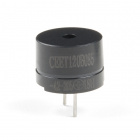
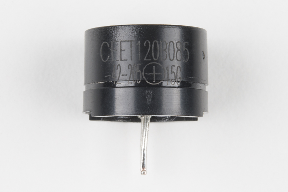
Buzzer
The buzzer uses a small magnetic coil to vibrate a metal disc inside a plastic housing. By pulsing electricity through the coil at different rates, different frequencies (pitches) of sound can be produced. Attaching a potentiometer to the output allows you to limit the amount of current moving through the buzzer and lower its volume.
New Concepts
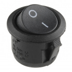
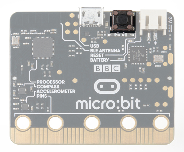
Reset Button
The RedBoard has a built-in reset button. This button will reset the board and start the code over from the beginning, running what is in setup() and then loop().
Tone Function
The tone function controls the pitch of the buzzer. This function is similar to PWM in that it generates a wave of a certain frequency on the specified pin. The frequency and duration can both be passed to the tone() function when calling it. To turn the tone off, you need to call noTone() or pass a duration of time for it to play and then stop. Unlike PWM, tone() can be used on any digital pin.
Arrays
Arrays operate like variables but they can store multiple values. The simplest array is just a list. Imagine that you want to store the frequency for each note of the C major scale. We could make seven variables and assign a frequency to each one, or we could use an array and store all seven in the same array, as shown below. To refer to a specific value in the array, an index number is used. Arrays are indexed from 0. For example, to call the first element in the array, use array_name[0];; to call the second element, use array_name[1]; and so on.
| Musical Note | Frequency (Hz) | Using Variables | Using an Array |
|---|
| A | 220 | aFrequency | frequency[0] |
| B | 247 | bFrequency | frequency[1] |
| C | 261 | cFrequency | frequency[2] |
| D | 294 | dFrequency | frequency[3] |
| E | 330 | eFrequency | frequency[4] |
| F | 349 | fFrequency | frequency[5] |
| G | 392 | gFrequency | frequency[6] |
Hardware Hookup
| Polarized Components | Pay special attention to the component’s markings indicating how to place it on the breadboard. Polarized components can only be connected to a circuit in one direction. |
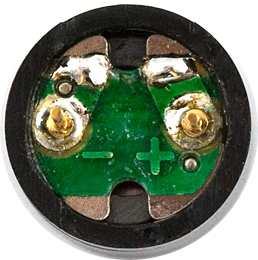
The buzzer is polarized. To see which leg is positive and which is negative, flip the buzzer over and look at the markings underneath. Keep track of which pin is where, as they will be hard to see once inserted into the breadboard. There is also text on the positive side of the buzzer, along with a tiny (+) symbol.
Volume Knob
All of the circuits with the buzzer make use of a potentiometer as a rudimentary volume knob. Notice that only two of the potentiometer's legs are used in these circuits. In these instances, the potentiometer is acting as a variable resistor, limiting the amount of current flowing to the speaker and thus affecting the volume as you turn the knob. This is similar to the current-limiting resistor used to limit current to the LED in circuit 1 --- only this time the resistance is variable.
Ready to start hooking everything up? Check out the circuit diagram and hookup table below to see how everything is connected.
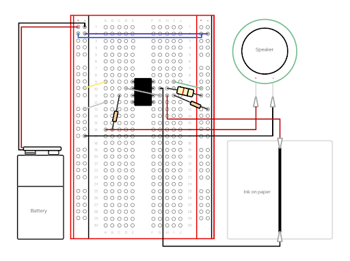
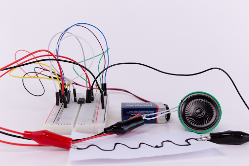
Circuit Diagram
Having a hard time seeing the circuit? Click on the image for a closer look.
Hookup Table
| Component | RedBoard | Breadboard | Breadboard | Breadboard |
|---|
| Buzzer | | J1 (Buzzer + ) | J3 (Buzzer - ) | |
| Potentiometer | | B1 | B2 | B3 |
| Jumper Wire | GND | GND Rail ( - ) | | |
| Jumper Wire | Digital Pin 10 | F1 | | |
| Jumper Wire | | E2 | GND Rail ( - ) | |
| Jumper Wire | | E1 | F3 |
In the table, polarized components are shown with a warning triangle and the whole row highlighted yellow. Open the Sketch
Open the example code from your Arduino sketchbook or copy and paste the following code into the Arduino IDE. Hit upload, and see what happens!
language:cpp
/*
SparkFun Tinker Kit
Circuit 5: Buzzer

Play notes using a buzzer connected to pin 10

This sketch was written by SparkFun Electronics, with lots of help from the Arduino community.
This code is completely free for any use.

View circuit diagram and instructions at: https://learn.sparkfun.com/tutorials/activity-guide-for-sparkfun-tinker-kit/
Download drawings and code at: https://github.com/sparkfun/SparkFun_Tinker_Kit_Code/
*/


int speakerPin = 10;               //the pin that buzzer is connected to

void setup()
{
  pinMode(speakerPin, OUTPUT);    //set the output pin for the speaker
}

void loop()
{

  play('g', 2);       //ha
  play('g', 1);       //ppy
  play('a', 4);       //birth
  play('g', 4);       //day
  play('C', 4);       //to
  play('b', 4);       //you

  play(' ', 2);       //pause for 2 beats

  play('g', 2);       //ha
  play('g', 1);       //ppy
  play('a', 4);       //birth
  play('g', 4);       //day
  play('D', 4);       //to
  play('C', 4);       //you

  play(' ', 2);       //pause for 2 beats

  play('g', 2);       //ha
  play('g', 1);       //ppy
  play('G', 4);       //birth
  play('E', 4);       //day
  play('C', 4);       //dear
  play('b', 4);       //your
  play('a', 6);       //name

  play(' ', 2);       //pause for 2 beats

  play('F', 2);       //ha
  play('F', 1);       //ppy
  play('E', 4);       //birth
  play('C', 4);       //day
  play('D', 4);       //to
  play('C', 6);       //you

  while(true){}       //get stuck in this loop forever so that the song only plays once
}


void play( char note, int beats)
{
  int numNotes = 14;  // number of notes in our note and frequency array (there are 15 values, but arrays start at 0)

  //Note: these notes are C major (there are no sharps or flats)

  //this array is used to look up the notes
  char notes[] = { 'c', 'd', 'e', 'f', 'g', 'a', 'b', 'C', 'D', 'E', 'F', 'G', 'A', 'B', ' '};
  //this array matches frequencies with each letter (e.g. the 4th note is 'f', the 4th frequency is 175)
  int frequencies[] = {131, 147, 165, 175, 196, 220, 247, 262, 294, 330, 349, 392, 440, 494, 0};

  int currentFrequency = 0;    //the frequency that we find when we look up a frequency in the arrays
  int beatLength = 150;   //the length of one beat (changing this will speed up or slow down the tempo of the song)

  //look up the frequency that corresponds to the note
  for (int i = 0; i < numNotes; i++)  // check each value in notes from 0 to 14
  {
    if (notes[i] == note)             // does the letter passed to the play function match the letter in the array?
    {
      currentFrequency = frequencies[i];   // Yes! Set the current frequency to match that note
    }
  }

  //play the frequency that matched our letter for the number of beats passed to the play function
  tone(speakerPin, currentFrequency, beats * beatLength);
  delay(beats* beatLength);   //wait for the length of the tone so that it has time to play
  delay(50);                  //a little delay between the notes makes the song sound more natural

}

/* CHART OF FREQUENCIES FOR NOTES IN C MAJOR
Note      Frequency (Hz)
c        131
d        147
e        165
f        175
g        196
a        220
b        247
C        262
D        294
E        330
F        349
G        392
A        440
B        494
*/
What You Should See
When the program begins, a song will play from the buzzer once. To replay the song, press the reset button on the RedBoard. Use the potentiometer to adjust the volume.
Program Overview
Inside the main loop:
- Play the first note for x number of beats using the play function.
- (Inside the play function:) Take the note passed to the play function and compare it to each letter in the notes array. When you find a note that matches, remember the index position of that note (e.g., 6th entry in the notes array).
- Get a frequency from the frequency array that has the same index as the note that matched (e.g., the 6th frequency).
- Play that frequency for the number of beats passed to the play function.
- Play the second note using the play function
...and so on.
Code to Note
| Code | Description |
|---|
Character Variables:
void play( char note, int beats) | The char, or character, variable to store character values. For example, in this sketch, the play() function gets passed two variables, a character variable that represents the mucial note we want to play and an integer variable that represents how long to play that note. A second array takes the character variable and associates a frequency value to it. This makes programming a song easier as you can just reference the character and not the exact frequency. |
Tone Function:
tone(pin, frequency, duration); | The tone() function will pulse power to a pin at a specific frequency. The duration controls how long the sound will play. Tone can be used on any digital pin. |
Declaring an Array:
arrray_name[array_size]; or arrray_name[] = {array elements}; | To declare an array, you must give it a name, then either tell Arduino how many positions the array will have or assign a list of values to the array. |
Calling an Array:
array_name[index #]; | To call one of the values in an array, simply type the name of the array and the index of the value. You can use a variable instead of a number in between the square brackets. Don't forget the index starts at 0, not 1, so to call the first element, use array_name[0];. |
Coding Challenges
| Challenge | Description |
|---|
| Change the tempo of the song | Experiment with the beatLength; variable to change the tempo of the song. |
| Make your own song | Try changing the notes to make a different song. Spaces "" can be used for rests in the song. |
Troubleshooting
| Problem | Solution |
|---|
| The song is too quiet or too loud | Turn the potentiometer to adjust the volume. |
| No sound is playing | Try pressing the reset button on the RedBoard. If that doesn’t work, check your wiring of the buzzer. It's easy to misalign a pin with a jumper wire. |
Circuit 6: Digital Trumpet
Learn about digital inputs and buttons as you build your own digital trumpet!
Parts Needed
Gather the following parts to build the circuit:
- 1x Breadboard
- 1x SparkFun RedBoard
- 10x Jumper Wires
- 1x 10K Potentiometer
- 1x Buzzer
- 1x Green Push Button
- 1x Yellow Push Button
- 1x Red Push Button
Didn't Get the Tinker Kit?
If you are conducting this experiment and didn't get the Tinker Kit, we suggest using these parts:
In stock
PRT-12002
This is your tried and true white solderless breadboard. It has 2 power buses, 10 columns, and 30 rows - a total of 400 tie i…
42In stock
DEV-15123
The SparkFun RedBoard Qwiic is an Arduino-compatible development board with a built in Qwiic connector, eliminating the need …
9In stock
COM-09806
This 10K trimmable potentiometer has a small knob built right in and it's breadboard friendly to boot!
6In stock
PRT-14460
This is a simple 4-pack of momentary, multicolor buttons, great for all sorts of projects! Unlike previous iterations of mult…
In stock
PRT-11026
If you need to knock up a quick prototype there's nothing like having a pile of jumper wires to speed things up, and let's fa…
20In stock
COM-07950
We drove it directly from a 5V PIC to generate the tones for our Simon demonstration game.
5New Components
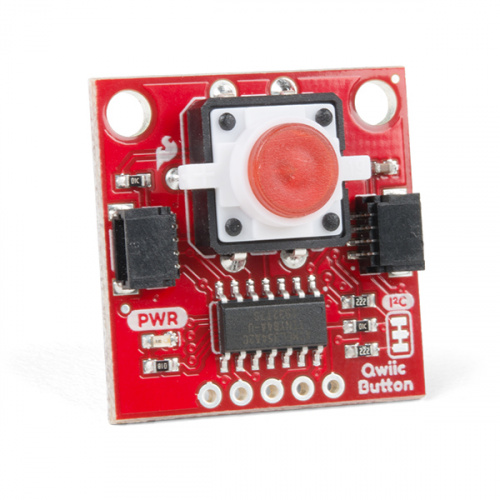
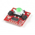
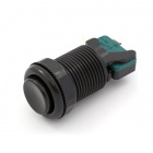
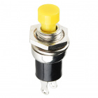
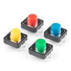
Buttons
Buttons, also known as momentary switches, are switches that only remain in their on state as long as they’re being actuated, or pressed. Most often momentary switches are best used for intermittent user-input cases: reset button and keypad buttons. These switches have a nice, tactile, “clicky” feedback when you press them.
Note that the different colors are just aesthetic. All of the buttons included behave the same no matter their color.
New Concepts
Binary Number System
Number systems are the methods we use to represent numbers. We’ve all been mostly operating within the comfy confines of a base-10 number system, but there are many others. The base-2 system, otherwise known as binary, is common when dealing with computers and electronics. There are really only two ways to represent the state of anything: ON or OFF, HIGH or LOW, 1 or 0. And so, almost all electronics rely on a base-2 number system to store and manipulate numbers. The heavy reliance electronics places on binary numbers means it’s important to know how the base-2 number system works.
Digital Input
In circuit 1, you worked with digital outputs. This circuit focuses on digital inputs. Digital inputs only care if something is in one of two states: TRUE or FALSE, HIGH or LOW, ON or OFF. Digital inputs are great for determining if a button has been pressed or if a switch has been flipped.
Pull-up Resistors
A pull-up resistor is a small circuit that holds the voltage HIGH (5V) on a pin until a button is pressed, pulling the voltage LOW (0V). The most common place you will see a pull-up resistor is when working with buttons. A pull-up resistor keeps the button in one state until it is pressed. The RedBoard has built-in pull-up resistors, but they can also be added to a circuit externally. This circuit uses the internal pull-up resistors, covered in more detail in the Code to Note section.
Hardware Hookup
Buttons are not polarized. However, they do merit a closer look. Buttons make momentary contact from one connection to another, so why are there four legs on each button? The answer is to provide more stability and support to the buttons in your breadboard circuit. Each row of legs is connected internally. When the button is pressed, one row connects to the other, making a connection between all four pins.
If the button's legs don't line up with the slots on the breadboard, rotate it 90 degrees.
Ready to start hooking everything up? Check out the circuit diagram and hookup table below to see how everything is connected.
Circuit Diagram
Having a hard time seeing the circuit? Click on the image for a closer look.
Hookup Table
| Component | RedBoard | Breadboard | Breadboard | Breadboard |
|---|
| Buzzer | | J1 (Buzzer + ) | J3 (Buzzer - ) | |
| Potentiometer | | B1 | B2 | B3 |
| Jumper Wire | GND | GND Rail ( - ) | | |
| Jumper Wire | Digital Pin 10 | F1 | | |
| Jumper Wire | | E2 | GND Rail ( - ) | |
| Jumper Wire | | E1 | F3 | |
| Push Button | | D16/D18 | G16/G18 | |
| Push Button | | D22/D24 | G22/G24 | |
| Push Button | | D28/D30 | G28/G30 | |
| Jumper Wire | Digital Pin 4 | J18 | | |
| Jumper Wire | Digital Pin 3 | J24 | | |
| Jumper Wire | Digital Pin 2 | J30 | | |
| Jumper Wire | | J16 | GND Rail ( - ) | |
| Jumper Wire | | J22 | GND Rail ( - ) | |
| Jumper Wire | | J28 | GND Rail ( - ) | |
In the table, polarized components are shown with a warning triangle and the whole row highlighted yellow. Open the Sketch
Open the example code from your Arduino sketchbook or copy and paste the following code into the Arduino IDE. Hit upload, and see what happens!
language:cpp
/*
SparkFun Tinker Kit
Circuit 6: Digital Trumpet

Use 3 buttons plugged to play musical notes on a buzzer.

This sketch was written by SparkFun Electronics, with lots of help from the Arduino community.
This code is completely free for any use.

View circuit diagram and instructions at: https://learn.sparkfun.com/tutorials/activity-guide-for-sparkfun-tinker-kit/
Download drawings and code at: https://github.com/sparkfun/SparkFun_Tinker_Kit_Code/
*/

//set the pins for the button and buzzer
int firstKeyPin = 2;
int secondKeyPin = 3;
int thirdKeyPin = 4;

int buzzerPin = 10;


void setup() {
  //set the button pins as inputs
  pinMode(firstKeyPin, INPUT_PULLUP);
  pinMode(secondKeyPin, INPUT_PULLUP);
  pinMode(thirdKeyPin, INPUT_PULLUP);

  //set the buzzer pin as an output
  pinMode(buzzerPin, OUTPUT);
}

void loop() {

  if(digitalRead(firstKeyPin) == LOW){        //if the first key is pressed
    tone(buzzerPin, 262);                     //play the frequency for c
  }
  else if(digitalRead(secondKeyPin) == LOW){  //if the second key is pressed
    tone(buzzerPin, 330);                     //play the frequency for e
  }
  else if(digitalRead(thirdKeyPin) == LOW){   //if the third key is pressed
    tone(buzzerPin, 392);                     //play the frequency for g
  }
  else{
    noTone(buzzerPin);                        //if no key is pressed turn the buzzer off
  }
}

  /*
  note  frequency
  c     262 Hz
  d     294 Hz
  e     330 Hz
  f     349 Hz
  g     392 Hz
  a     440 Hz
  b     494 Hz
  C     523 Hz
  */
What You Should See
Different tones will play when you press different keys. Turning the potentiometer will adjust the volume.
Program Overview
- Check to see if the first button is pressed.
a. If it is, play the frequency for c.
b. If it isn’t, skip to the next else if statement.
- Check to see if the second button is pressed.
a. If it is, play the frequency for e.
b. If it isn’t, skip to the next else if statement.
- Check to see if the second button is pressed.
a. If it is, play the frequency for g.
b. If it isn’t, skip to the next else if statement.
- If none of the if statements are true
a. Turn the buzzer off.
Code to Note
| Code | Description |
|---|
Internal Pull-Up Resistor:
pinMode(firstKeyPin, INPUT_PULLUP); | To declare a standard input, use the line pinMode(pin_name, INPUT). If you would like to use one of the RedBoard's built-in pull-up 20kΩ resistors, it would look like this: pinMode(firstKeyPin, INPUT_PULLUP);. The advantage of external pull-ups is being able to choose a more exact value for the resistor. |
Digital Input:
digitalRead(pin); | Check to see if an input pin is reading HIGH (5V) or LOW (0V). Returns TRUE (1) or FALSE (0) depending on the reading. |
Is Equal to:
if(digitalRead(firstKeyPin) == LOW) | This is another logical operator. The 'is equal to' symbol (==) can be confusing. Two equals signs are equivalent to asking, "Are these two values equal to one another?" On the other hand, one equals sign in code is assigning a particular variable to a value. Don't forget to add the second equals sign if you are comparing two values. |
Coding Challenges
| Challenge | Description |
|---|
| Change the key of each button | Use the frequency table in the comment section at the end of the code to change the notes that each button plays. |
| Play more than three notes with if statements | By using combinations of buttons, you can play up to seven notes of the scale. You can do this in a few ways. To get more practice with if statements, try adding seven if statements and using the Boolean AND (&&) operator to represent all of the combinations of keys. |
| Play more than three notes with binary math | You can use a clever math equation to play more than three notes with your three keys. By multiplying each key by a different number, then adding up all of these numbers, you can make a math equation that produces a different number for each combination of keys. |
Troubleshooting
| Problem | Solution |
|---|
| The buzzer is too loud or too quiet | Turn the potentiometer to adjust the volume. |
| The RedBoard thinks one key is always pressed | Check your wiring. You may have ground and 5V backward if one or more buttons behave as though they're pressed all the time. |
| The buttons are not working | First, make sure that the wiring is correct. It is easy to misalign a wire with a button leg. Second, make sure that you have declared your buttons as inputs and have enabled the internal pull-up resistors with INPUT_PULLUP. |
Circuit 7: Simon Says Game
The Simon Says game uses LEDs to flash a pattern, which the player must remember and repeat using four buttons. The classic [Simon](https://en.wikipedia.org/wiki/Simon_(game)) game has been a hit since the 1980s. Now you can build your own!
Parts Needed
You will need the following parts:
- 1x Breadboard
- 1x SparkFun RedBoard
- 16x Jumper Wires
- 4x 330Ω Resistor
- 1x 10K Potentiometer
- 1x Buzzer
- 1x Blue LED
- 1x Blue Push Button
- 1x Green LED
- 1x Green Push Button
- 1x Yellow LED
- 1x Yellow Push Button
- 1x Red LED
- 1x Red Push Button
Didn't Get the Tinker Kit?
If you are conducting this experiment and didn't get the Tinker Kit, we suggest using these parts:
In stock
PRT-12002
This is your tried and true white solderless breadboard. It has 2 power buses, 10 columns, and 30 rows - a total of 400 tie i…
42In stock
DEV-15123
The SparkFun RedBoard Qwiic is an Arduino-compatible development board with a built in Qwiic connector, eliminating the need …
9In stock
COM-09806
This 10K trimmable potentiometer has a small knob built right in and it's breadboard friendly to boot!
6In stock
COM-12062
We all know that you can never get too many LEDs. Don't worry, we've got you covered. This is a pack of basic red, yellow, bl…
8In stock
PRT-14460
This is a simple 4-pack of momentary, multicolor buttons, great for all sorts of projects! Unlike previous iterations of mult…
In stock
PRT-11026
If you need to knock up a quick prototype there's nothing like having a pile of jumper wires to speed things up, and let's fa…
20In stock
COM-07950
We drove it directly from a 5V PIC to generate the tones for our Simon demonstration game.
5In stock
PRT-14490
These are your run-of-the-mill 1/4 Watt, +/- 5% tolerance PTH resistors. Commonly used in breadboards and other prototyping a…
New Concepts
For Loops
For loops repeat a section of code a set number of times. The loop works by using a counter (usually programmers use the letter “i” for this variable) that increases each loop until it reaches a stop value. Here’s an example of a simple for loop:
language:c
for (int i = 0; i < 5; i++){
    Serial.print(i);
}
The for loop takes three parameters in the brackets, separated by semicolons. The first parameter is the start value. In this case, integer i starts at 0. The second value is the stop condition. In this case, we stop the loop when i is no longer less than 5 (i < 5 is no longer true). The final parameter is an increment value. i++ is shorthand for increase i by 1 each time, but you could also increase i by different amounts. This loop would repeat five times. Each time it would run the code in between the brackets, which prints the value of i to the serial monitor.
Measuring Durations of Time With millis()
The RedBoard has a built-in clock that keeps accurate time. You can use the millis() command to see how many milliseconds have passed since the RedBoard was last powered. By storing the time when an event happens and then subtracting the current time, you can measure the number of milliseconds (and thus seconds) that have passed. This sketch uses this function to set a time limit for repeating the pattern.
Custom Functions
This sketch uses several user-defined functions. These functions perform operations that are needed many times in the program (for example, reading which button is currently pressed or turning all of the LEDs off). Functions are essential to make more complex programs readable and compact.
Hardware Hookup
Ready to start hooking everything up? Check out the circuit diagram and hookup table below to see how everything is connected.
Circuit Diagram
Having a hard time seeing the circuit? Click on the image for a closer look.
Hookup Table
| Component | RedBoard | Breadboard | Breadboard | Breadboard |
|---|
| Buzzer | | J1 (Buzzer + ) | J3 (Buzzer - ) | |
| Potentiometer | | B1 | B2 | B3 |
| Jumper Wire | GND | GND Rail ( - ) | | |
| Jumper Wire | Digital Pin 10 | F1 | | |
| Jumper Wire | | E2 | GND Rail ( - ) | |
| Jumper Wire | | E1 | F3 | |
| Push Button | | D10/D12 | G10/G12 | |
| Push Button | | D16/D18 | G16/G18 | |
| Push Button | | D22/D24 | G22/G24 | |
| Push Button | | D28/D30 | G28/G30 | |
| Jumper Wire | Digital Pin 8 | J12 | | |
| Jumper Wire | Digital Pin 6 | J18 | | |
| Jumper Wire | Digital Pin 4 | J24 | | |
| Jumper Wire | Digital Pin 2 | J30 | | |
| Jumper Wire | | J10 | GND Rail ( - ) | |
| Jumper Wire | | J16 | GND Rail ( - ) | |
| Jumper Wire | | J22 | GND Rail ( - ) | |
| Jumper Wire | | J28 | GND Rail ( - ) | |
| Blue LED | | H7 LED ( + ) | H8 LED ( - ) | |
| Green LED | | H13 LED ( + ) | H14 LED ( - ) | |
| Yellow LED | | H19 LED ( + ) | H20 LED ( - ) | |
| Red LED | | H25 LED ( + ) | H26 LED ( - ) | |
| Jumper Wire | Digital Pin 9 | J7 | | |
| Jumper Wire | Digital Pin 7 | J13 | | |
| Jumper Wire | Digital Pin 5 | J19 | | |
| Jumper Wire | Digital Pin 3 | J25 | | |
330Ω Resistor
(orange, orange, brown) | | J8 | GND Rail ( - ) | |
330Ω Resistor
(orange, orange, brown) | | J14 | GND Rail ( - ) | |
330Ω Resistor
(orange, orange, brown) | | j20 | GND Rail ( - ) | |
330Ω Resistor
(orange, orange, brown) | | J26 | GND Rail ( - ) | |
In the table, polarized components are shown with a warning triangle and the whole row highlighted yellow. Open the Sketch
Open the example code from your Arduino sketchbook or copy and paste the following code into the Arduino IDE. Hit upload, and see what happens!
language:cpp
/*
SparkFun Tinker Kit
Circuit 7: Simon Says Game

The Simon Says game flashes a pattern using LED lights, then the player must repeat the pattern.

This sketch was written by SparkFun Electronics, with lots of help from the Arduino community.
This code is completely free for any use.

View circuit diagram and instructions at: https://learn.sparkfun.com/tutorials/activity-guide-for-sparkfun-tinker-kit/
Download drawings and code at: https://github.com/sparkfun/SparkFun_Tinker_Kit_Code/
*/

//set the pins where the butons, LEDs and buzzer connect
int button[] = {2,4,6,8};     //red is button[0], yellow is button[1], green is button[2], blue is button[3]
int led[] = {3,5,7,9};        //red is led[0], yellow is led[1], green is led[2], blue is led[3]
int tones[] = {262, 330, 392, 494};   //tones to play with each button (c, e, g, b)

int roundsToWin = 10;         //number of rounds the player has to play before they win the game (the array can only hold up to 16 rounds)
int buttonSequence[16];       //make an array of numbers that will be the sequence that the player needs to remember

int buzzerPin = 10;           //pin that the buzzer is connected to

int pressedButton = 4;        //a variable to remember which button is being pressed. 4 is the value if no button is being pressed.
int roundCounter = 1;         //keeps track of what round the player is on


long startTime = 0;           //timer variable for time limit on button press
long timeLimit = 2000;        //time limit to hit a button

boolean gameStarted = false;      //variable to tell the game whether or not to play the start sequence

void setup(){

  //set all of the button pins to input_pullup (use the builtin pullup resistors)
  pinMode(button[0], INPUT_PULLUP);
  pinMode(button[1], INPUT_PULLUP);
  pinMode(button[2], INPUT_PULLUP);
  pinMode(button[3], INPUT_PULLUP);

  //set all of the LED pins to output
  pinMode(led[0], OUTPUT);
  pinMode(led[1], OUTPUT);
  pinMode(led[2], OUTPUT);
  pinMode(led[3], OUTPUT);

  pinMode(buzzerPin, OUTPUT);   //set the buzzer pin to output
}

void loop(){

if (gameStarted == false){    //if the game hasn't started yet
  startSequence();            //flash the start sequence
  roundCounter = 0;           //reset the round counter
  delay(1500);                //wait a second and a half
  gameStarted = true;         //set gameStarted to true so that this sequence doesn't start again
}

//each round, start by flashing out the sequence to be repeated
for(int i=0; i <= roundCounter; i++){   //go through the array up to the current round number
  flashLED(buttonSequence[i]);          //turn on the LED for that array position and play the sound
  delay(200);                           //wait
  allLEDoff();                          //turn all of the LEDs off
  delay(200);
}

//then start going through the sequence one at a time and see if the user presses the correct button
for(int i=0; i <= roundCounter; i++){   //for each button to be pressed in the sequence

  startTime = millis();                 //record the start time

  while(true){  //loop until the player presses a button or the time limit is up (the time limit check is in an if statement)

    pressedButton = buttonCheck();      //every loop check to see which button is pressed

    if (pressedButton < 4){             //if a button is pressed... (4 means that no button is pressed)

      flashLED(pressedButton);          //flash the LED for the button that was pressed

      if(pressedButton == buttonSequence[i]){   //if the button matches the button in the sequence
          delay(250);                   //leave the LED light on for a moment
          allLEDoff();                  //then turn off all of the lights and
          break;                        //end the while loop (this will go to the next number in the for loop)

      } else{                           //if the button doesn't match the button in the sequence
          loseSequence();               //play the lose sequence (the loose sequence stops the program)
          break;                        //when the program gets back from the lose sequence, break the while loop so that the game can start over
      }

    } else {                            //if no button is pressed
      allLEDoff();                      //turn all the LEDs off
    }

    //check to see if the time limit is up
    if(millis() - startTime > timeLimit){   //if the time limit is up
      loseSequence();                       //play the lose sequence
      break;                                //when the program gets back from the lose sequence, break the while loop so that the game can start over
    }
  }
}

  roundCounter = roundCounter + 1;      //increase the round number by 1

  if (roundCounter >= roundsToWin){               //if the player has gotten to the 16th round
    winSequence();                      //play the winning song
  }

  delay(500);                           //wait for half a second between rounds


}

//----------FUNCTIONS------------

//FLASH LED
void flashLED (int ledNumber){
  digitalWrite(led[ledNumber], HIGH);
  tone(buzzerPin, tones[ledNumber]);
}

//TURN ALL LEDS OFF
void allLEDoff (){
  //turn all the LEDs off
  digitalWrite(led[0],LOW);
  digitalWrite(led[1],LOW);
  digitalWrite(led[2],LOW);
  digitalWrite(led[3],LOW);
  //turn the buzzer off
  noTone(buzzerPin);
}

//CHECK WHICH BUTTON IS PRESSED
int buttonCheck(){
  //check if any buttons are being pressed
  if(digitalRead(button[0]) == LOW){
    return 0;
  }else if(digitalRead(button[1]) == LOW){
    return 1;
  }else if(digitalRead(button[2]) == LOW){
    return 2;
  }else if(digitalRead(button[3]) == LOW){
    return 3;
  }else{
    return 4; //this will be the value for no button being pressed
  }
}

//START SEQUENCE
void startSequence(){

  randomSeed(analogRead(A0));   //make sure the random numbers are really random

  //populate the buttonSequence array with random numbers from 0 to 3
  for (int i=0;i<=roundsToWin;i++){
    buttonSequence[i] = round(random(0,4));
  }

  //flash all of the LEDs when the game starts
  for(int i=0; i<=3; i++){

    tone(buzzerPin, tones[i], 200); //play one of the 4 tones

    //turn all of the leds on
    digitalWrite(led[0],HIGH);
    digitalWrite(led[1],HIGH);
    digitalWrite(led[2],HIGH);
    digitalWrite(led[3],HIGH);

    delay(100);         //wait for a moment

    //turn all of the leds off
    digitalWrite(led[0],LOW);
    digitalWrite(led[1],LOW);
    digitalWrite(led[2],LOW);
    digitalWrite(led[3],LOW);

    delay(100);   //wait for a moment

  } //this will repeat 4 times
}

//WIN SEQUENCE
void winSequence(){

  //turn all the LEDs on
  for(int j=0; j<=3; j++){
    digitalWrite(led[j], HIGH);
  }

  //play the 1Up noise
  tone(buzzerPin, 1318, 150);   //E6
  delay(175);
  tone(buzzerPin, 1567, 150);   //G6
  delay(175);
  tone(buzzerPin, 2637, 150);   //E7
  delay(175);
  tone(buzzerPin, 2093, 150);   //C7
  delay(175);
  tone(buzzerPin, 2349, 150);   //D7
  delay(175);
  tone(buzzerPin, 3135, 500);   //G7
  delay(500);

  //wait until a button is pressed
  do {
    pressedButton = buttonCheck();
  } while(pressedButton > 3);
  delay(100);

  gameStarted = false;   //reset the game so that the start sequence will play again.

}

//LOSE SEQUENCE
void loseSequence(){

  //turn all the LEDs on
  for(int j=0; j<=3; j++){
    digitalWrite(led[j], HIGH);
  }

  //play the 1Up noise
  tone(buzzerPin, 130, 250);   //E6
  delay(275);
  tone(buzzerPin, 73, 250);   //G6
  delay(275);
  tone(buzzerPin, 65, 150);   //E7
  delay(175);
  tone(buzzerPin, 98, 500);   //C7
  delay(500);

  //wait until a button is pressed
  do {
    pressedButton = buttonCheck();
  } while(pressedButton > 3);
  delay(200);

  gameStarted = false;   //reset the game so that the start sequence will play again.
}
What You Should See
The circuit will flash all of the LEDs and play a melody. After a few seconds, it will flash the first light in the pattern. If you repeat the pattern correctly by pressing the corresponding colored button, then the game will move to the next round and add another color to the pattern sequence. If you make a mistake, the loss melody will play. If you get to round 10, the win melody will play. Press any button to start a new game.
Program Overview
- Check if a new game is starting. If it is, play the start sequence. Reset the counter that keeps track of rounds, and randomly generate a sequence of numbers from 0 to 3 that control which LEDs the user will have to remember.
- The game works in rounds that progress from 0 to 10. Each round the game will flash LEDs in a pattern, then the player has to recreate the pattern by pressing the button(s) that match the LED(s). In the first round, one LED will flash, and the player will have to press one button. In the eighth round, eight LEDs will flash, and the player will have to press eight buttons.
- Use a loop to flash LEDs from the sequence until you have flashed the number of LEDs that matches the round number (1 for round 1, 2 for round 2, etc).
- Start a timer, and wait for the player to press a button. The player has 1.5 seconds to press the correct button.
a. If the time limit runs out before a button is pressed, the player loses.
b. If the player presses the wrong button, the player loses.
c. If the player presses the right button, move on to the next number in the sequence.
d. Repeat this process until the player has lost or correctly repeated the sequence for this round.
- If the player repeats the entire sequence for that round. Increase the round number by one (this will add one extra item to the end of the pattern). Then go back to step 3.
- Keep incrementing the round until the player loses or the player finishes 10 rounds. If the player finishes 10 rounds, play the winning sequence.
Code to Note
| Code | Description |
|---|
Elapsed Time:
millis(); | The millis function returns the number of milliseconds that have passed since the RedBoard was last turned on. |
Boolean Variables:
boolean variable_name; |
The name for these variables comes from Boolean logic. The Boolean variable type only has two values: 1 or 0, HIGH or LOW, TRUE or FALSE. Using Boolean variables helps save memory on your microcontroller if you only need to know if something is true or false. Space in your microcontroller's memory is reserved when a variable is declared. How much memory is reserved depends on the type of variable. |
Storing pin numbers in Arrays:
int led[] = {3,5,7,9}; | Sometimes you will want to cycle through all of the LEDs or buttons connected to a project. You can do this by storing a sequence of pin numbers in an array. The advantage of having pins in an array instead of a sequence of variables is that you can use a loop to easily cycle through each pin. |
| User Functions | Description |
|---|
flashLED(# for LED to flash); | This turns one of the four LEDs on and plays the tone associated with it.
0 = Red, 1 = Yellow, 2 = Green, 3 = Blue.
|
allLEDoff(); | Turns all four LEDs off. |
buttonCheck(); | Uses digitalRead() to check which button is pressed. Returns 0, 1, 2 or 3 if one of the buttons is pressed. Returns 4 if no button is pressed.
|
startSequence(); | Flashes the LEDs and plays tones in a sequence. Resets the round counter and generates a new random sequence for the user to remember. |
winSequence(); | Plays a sequence of tones, turns all of the LEDs on, then waits for the player to press a button. If a button is pressed, restarts the game. |
loseSequence(); | Plays a sequence of tones, turns all of the LEDs on, then waits for the player to press a button. If a button is pressed, restarts the game. |
Coding Challenges
| Challenge | Description |
|---|
| Change the difficulty of the game | Change the difficulty of the game by changing how fast the player has to press each button or by increasing or decreasing the number of rounds needed to win.
Note that if you increase the number of rounds to be larger than 16, you will need to change the size of the “buttonSequence” array (it is set at the top of the code in a line that looks like this: int buttonSequence[16];.
|
| Change the sound effects | Try changing the sequence of notes that play when you start, win or lose the game. |
| 2-Player mode | Ready for a real coding challenge? Try changing the code so that two players can play head-to-head. |
Troubleshooting
| Problem | Solution |
|---|
| One of the LEDs isn’t lighting up | Make sure your LED is flipped around in the right direction. If the LED still doesn’t work, try wiggling the resistor and the wires that connect to the LED. |
| The buzzer is too loud or too quiet | Turn the potentiometer to adjust the volume |
| One of the buttons isn’t working | Carefully check your wiring for each button. One leg of the button should connect to a pin on the RedBoard; the other leg should connect to the ground rail on the breadboard. |
| None of the buttons or LEDs is working | Make sure you don't have 5V and GND mixed up. Double check that you have a GND connection from the RedBoard to the GND rail on the breadboard. |
| Still not working? | Jumper wires unfortunately can go "bad" from getting bent too much. The copper wire inside can break, leaving an open connection in your circuit. If you are certain that your circuit is wired correctly and that your code is error-free and uploaded, but you are still encountering issues, try replacing one or more of the jumper wires for the component that is not working. |
Circuit 8: Servo Motors
In this circuit, you will learn how to wire a servo and control it with code. Servo motors can be told to move to a specific position and stay there. Low-cost servo motors were originally used to steer remote-controlled airplanes and cars, but they have become popular for any project where precise movement is needed.
Parts Needed
You will need the following parts:
- 1x Breadboard
- 1x SparkFun RedBoard
- 8x Jumper Wires
- 1x 10K Potentiometer
- 1x Servo
Didn't Get the Tinker Kit?
If you are conducting this experiment and didn't get the Tinker Kit, we suggest using these parts:
In stock
PRT-12002
This is your tried and true white solderless breadboard. It has 2 power buses, 10 columns, and 30 rows - a total of 400 tie i…
42In stock
DEV-15123
The SparkFun RedBoard Qwiic is an Arduino-compatible development board with a built in Qwiic connector, eliminating the need …
9In stock
ROB-09065
Here is a simple, low-cost, high quality servo for all your mechatronic needs. This servo is very similar in size and specifi…
12In stock
COM-09806
This 10K trimmable potentiometer has a small knob built right in and it's breadboard friendly to boot!
6In stock
PRT-11026
If you need to knock up a quick prototype there's nothing like having a pile of jumper wires to speed things up, and let's fa…
20New Components
Servo Motors
Regular DC motors have two wires. When you hook the wires up to power, the motor spins around and around. Servo motors, on the other hand, have three wires: one for power, one for ground and one for signal. When you send the right signal through the signal wire, the servo will move to a specific angle and stay there. Common servos rotate over a range of 0° to 180°. The signal that is sent is a PWM signal, the same used to control the RGB LED.
New Concepts
Duty Cycle
The Pulse Width Modulation (PWM) hardware available on a microcontroller is a great way to generate servo control signals. When talking about how long a PWM signal is on, this is referred to as duty cycle. Duty cycle is measured in percentage. The percentage of duty cycle specifically describes the percentage of time a digital signal is on over an interval or period of time. The variation in the duty cycle tells the servo which position to go to in its rotation.
50%, 75% and 25% duty cycle examples
Arduino Libraries
Writing code that sends precise PWM signals to the servo would be time consuming and would require a lot more knowledge about the servo. Luckily, the Arduino IDE has hundreds of built-in and user-submitted containers of code that are called libraries. One of the built-in libraries, the Servo Library, allows us to control a servo with just a few lines of code!
To use one of the built-in Arduino libraries, all you have to do is "include" a link to its header file. A header file is a smaller code file that contains definitions for all the functions used in that library. By adding a link to the header file in your code, you are enabling your code to use all of those library functions. To use the Servo Library, you would add the following line to the top of your sketch.
language:cpp
#include <Servo.h>
Objects and Methods
To use the Servo Library, you will have to start by creating a servo object, like this:
language:cpp
Servo myServo;
Objects look a lot like variables, but they can do much more. Objects can store values, and they can have their own functions, which are called methods.
The most used method that a servo object has is .write().
language:cpp
myServo.write(90);
The write method takes one parameter, a number from 0 to 180, and moves the servo arm to the specified position (in this case, degree 90).
Why would we want to go to the trouble of making an object and a method instead of just sending a servo control signal directly over a pin? First, the servo object does the work of translating our desired position into a signal that the servo can read. Second, using objects makes it easy for us to add and control more than one servo.
Hardware Hookup
Polarized Components | Pay special attention to the component’s markings indicating how to place it on the breadboard. Polarized components can only be connected to a circuit in one direction. |
Servo motor connectors are polarized, but there is no place to attach them directly. Instead, connect three jumper wires to the female 3-pin header on the servo. This will make it so you can connect the servo to the breadboard.
The servo wires are color coded to make hookup simple. The pin-out is as follows:
| Pin | Description |
|---|
| White | Signal - PWM In |
| Red | Power (5V) |
| Black | Ground (GND) |
Included with your servo motor you will find a variety of motor mounts that connect to the shaft of your servo. You may choose to attach any mount you wish for this circuit. It will serve as a visual aid, making it easier to see the servo spin.
The various motor mounts included with your servo motor
Ready to start hooking everything up? Check out the Fritzing diagram below to see how everything is connected.
Circuit Diagram
Having a hard time seeing the circuit? Click on the image for a closer look.
Hookup Table
| Component | RedBoard | Breadboard | Breadboard | Breadboard | Servo |
|---|
| Potentiometer | | B1 | B2 | B3 | |
| Jumper Wire | Analog Pin 0 | E2 | | | |
| Jumper Wire | | E1 | 5V Rail ( + ) | | |
| Jumper Wire | | E3 | GND Rail ( - ) | | |
| Jumper Wire | 5V | 5V Rail ( + ) | | | |
| Jumper Wire | GND | GND Rail ( - ) | | | |
| Jumper Wire | Digital Pin 9 | | | | White Servo Pin |
| Jumper Wire | | | | 5V Rail ( + ) | Red Servo Pin |
| Jumper Wire | | | | GND Rail ( - ) | Black Servo Pin |
In the table, polarized components are shown with a warning triangle and the whole column highlighted yellow. Open the Sketch
Open the example code from your Arduino sketchbook or copy and paste the following code into the Arduino IDE. Hit upload, and see what happens!
language:cpp
/*
SparkFun Tinker Kit
Circuit 8: Servo Motors

Move a servo attached to pin 9 so that it's angle matches a potentitometer attached to A0.

This sketch was written by SparkFun Electronics, with lots of help from the Arduino community.
This code is completely free for any use.

View circuit diagram and instructions at: https://learn.sparkfun.com/tutorials/activity-guide-for-sparkfun-tinker-kit/
Download drawings and code at: https://github.com/sparkfun/SparkFun_Tinker_Kit_Code/
 */

#include <Servo.h>          //include the servo library

int potPosition;           //this variable will store the position of the potentiometer
int servoPosition;         //the servo will move to this position

Servo myservo;              //create a servo object

void setup() {

  myservo.attach(9);        //tell the servo object that its servo is plugged into pin 9

}

void loop() {


  potPosition = analogRead(A0);                     //use analog read to measure the position of the potentiometer (0-1023)

  servoPosition = map(potPosition, 0,1023,20,160);  //convert the potentiometer number to a servo position from 20-160
                                                    //Note: its best to avoid driving the little SIK servos all the
                                                    //way to 0 or 180 degrees it can cause the motor to jitter, which is bad for the servo.

  myservo.write(servoPosition);                      //move the servo to the 10 degree position
}
What You Should See
Turning the potentiometer will cause the servo to turn.
Program Overview
- Read the value of the potentiometer.
- Convert the potentiometer value (0--1023) to an angle (20--160).
- Tell the servo to go to this angle.
Code to Note
| Code | Description |
|---|
Including Libraries:
#include <Servo.h> | The #include command adds a library to your Arduino program. After you include a library, you can use the commands in the library in your program. This line adds the Servo library. |
Creating Servo Objects:
Servo myServo; | The Servo command creates a new servo object and assigns a name to it, myServo in this case. If you make more than one servo object, you will need to give them different names. |
Servo Attach:
myServo.attach(9); | The .attach() method tells the servo object to which pin the signal wire of its servo is attached. It will send position signals to this pin. In this sketch, pin 9 is used. Remember to only use digital pins that are capable of PWM. |
Range Mapping:
map(potPosition, 0,1023,20,160); | As shown in previous circuits, the analog pin values on your microcontroller vary from 0-1023. However, what if we want those values to control a servo motor that only accepts a value from 0-180? The answer is to use the map function. The map() function takes a range of values and outputs a different range of values that can contain more or less values than the original. In this case, we are taking the range 0-1023 and mapping it to the range 20-160. |
Servo Write:
myServo.write(90); | The .write() method moves the servo to a specified angle. In this example, the servo is being told to go to angle 90. |
Coding Challenges
| Challenge | Description |
|---|
| Reverse the direction | Try making the servo move in the opposite direction to the potentiometer. |
| Change the range | Try altering the map function so that moving the potentiometer a lot only moves the servo a little. |
| Swap in a different sensor | Try swapping a light sensor in for the potentiometer. You have just made a dial that reads how much light is present! |
Troubleshooting
| Problem | Solution |
|---|
| The servo doesn’t move | Check the wiring on your servo. Make sure that the red wire on the servo cord is connected to 5V, the black wire is connected to GND and the white signal wire is connected to pin 9. |
| The servo is twitching | Although these servos are supposed to move from 0 to 180 degrees, sometimes sending them to the extremes of their range causes them to twitch (the servo is trying to move farther than it can). Make sure that you aren’t telling the servo to move outside of the 20-160 degree range. |
Circuit 9: Temperature Sensor
Want to create a DIY environmental monitor or weather station? You can use a small, low-cost sensor like the TMP36 to make devices that track and respond to temperature. In this activity, you will read the raw 0--1023 value from the temperature sensor, calculate the actual temperature, and then print it out over the serial monitor.
Parts Needed
You will need the following parts:
- 1x Breadboard
- 1x SparkFun RedBoard
- 3x Jumper Wires
- 1x TMP36 Temperature Sensor
Didn't Get the Tinker Kit?
If you are conducting this experiment and didn't get the Tinker Kit, we suggest using these parts:
In stock
PRT-12002
This is your tried and true white solderless breadboard. It has 2 power buses, 10 columns, and 30 rows - a total of 400 tie i…
42In stock
DEV-15123
The SparkFun RedBoard Qwiic is an Arduino-compatible development board with a built in Qwiic connector, eliminating the need …
9In stock
PRT-11026
If you need to knock up a quick prototype there's nothing like having a pile of jumper wires to speed things up, and let's fa…
20In stock
SEN-10988
This is the same temperature sensor that is included in our [SparkFun Inventor's Kit](http://www.sparkfun.com/products/12060)…
17New Components
TMP36 Temperature Sensor
This temperature sensor has three legs. One connects to 5V, one to ground, and the voltage output from the third leg varies proportionally to changes in temperature. By doing some simple math with this voltage we can measure temperature in degrees Celsius or Fahrenheit.
New Concepts
Algorithms
An algorithm is a process used in order to achieve a desired result. Often, the information needed to create an algorithm lives in the part's datasheet. This sketch uses a few formulas to turn a voltage value into a temperature value, making them all part of the larger temperature-retrieving algorithm. The first formula takes the voltage read on analog pin 0 and multiplies it to get a voltage value from 0V--5V:
language:c
voltage = analogRead(A0) * 0.004882814;
The number we are multiplying by comes from dividing 5V by the number of samples the analog pin can read (1024), so we get: 5 / 1024 = 0.004882814.
The second formula takes that 0--5V value and calculates degrees Centigrade:
language:c
degreesC = (voltage - 0.5) * 100.0;
The reason 0.5V is subtracted from the calculated voltage is because there is a 0.5V offset, mentioned on page 8 of the TMP36 datasheet. It's then multiplied by 100 to get a value that matches temperature.
The last formula takes the Centigrade temperature and converts it to a Fahrenheit temperature using the standard conversion formula:
language:c
degreesF = degreesC * (9.0/5.0) + 32.0;
Together, these three formulas make up the algorithm that converts voltage to degrees Fahrenheit.
Hardware Hookup
| Polarized Components | Pay special attention to the component’s markings indicating how to place it on the breadboard. Polarized components can only be connected to a circuit in one direction. |
The temperature sensor is polarized and can only be inserted in one direction. See below for the pin outs of the temperature sensor. Pay very close attention to the markings on each side as you insert it into your circuit.
Heads up! Double check the polarity of the TMP36 temperature sensor before powering the RedBoard. It can become very hot if it is inserted backward!
Ready to start hooking everything up? Check out the circuit diagram and hookup table below to see how everything is connected.
Circuit Diagram
Having a hard time seeing the circuit? Click on the image for a closer look.
Hookup Table
| Component | RedBoard | Breadboard | Breadboard | Breadboard |
|---|
| TMP36 Temperature Sensor | | F6 (GND) | F7 (Signal) | F8 (V+) |
| Jumper Wire | | J6 | GND( - ) | |
| Jumper Wire | Analog Pin 0 (A0) | J7 | | |
| Jumper Wire | | J8 | 5V ( + ) | |
In the table, polarized components are shown with a warning triangle and the whole row highlighted yellow. Open the Sketch
Open the example code from your Arduino sketchbook or copy and paste the following code into the Arduino IDE. Hit upload, and see what happens!
language:cpp
/*
SparkFun Tinker Kit
Circuit 9: Temperature Sensor

Use the "serial monitor" window to read a temperature sensor.

This sketch was written by SparkFun Electronics, with lots of help from the Arduino community.
This code is completely free for any use.

View circuit diagram and instructions at: https://learn.sparkfun.com/tutorials/activity-guide-for-sparkfun-tinker-kit/
Download drawings and code at: https://github.com/sparkfun/SparkFun_Tinker_Kit_Code/

*/

//analog input pin constant
const int tempPin = 0;

//raw reading variable
int tempVal;

//voltage variable
float volts;

//final temperature variables
float tempC;
float tempF;

void setup()
{
  // start the serial port at 9600 baud
  Serial.begin(9600);
}


void loop()
{
 //read the temp sensor and store it in tempVal
 tempVal = analogRead(tempPin);

 //print out the 10 value from analogRead
 Serial.print("TempVal = ");
 Serial.print(tempVal);

 //print a spacer
 Serial.print(" **** ");

 //converting that reading to voltage by multiplying the reading by 5V (voltage of       //the RedBoard)
 volts = tempVal * 5;
 volts /= 1023.0;

 //print out the raw voltage over the serial port
 Serial.print("volts: ");
 Serial.print(volts, 3);

 //print out divider
 Serial.print(" **** ");

 //calculate temperature celsius from voltage
 //equation found on the sensor spec.
 tempC = (volts - 0.5) * 100 ;

// print the celcius temperature over the serial port
Serial.print(" degrees C: ");
Serial.print(tempC);

//print spacer
 Serial.print(" **** ");

// Convert from celcius to fahrenheit
tempF = (tempC * 9.0 / 5.0) + 32.0;

//print the fahrenheit temperature over the serial port
Serial.print(" degrees F: ");
Serial.println(tempF);

//wait a bit before taking another reading
delay(1000);
}
What You Should See
The Arduino serial monitor will show the temperature in Celsius and Fahrenheit. The temperature readings will update every second. An easy way to see the temperature change is to press your finger to the sensor.
Here's an example of what you should see in the Arduino IDE’s serial monitor:
TempVal = 223 **** volts: 0.719 ****  degrees C: 21.94 ****  degrees F: 71.48
TempVal = 224 **** volts: 0.723 ****  degrees C: 22.26 ****  degrees F: 72.06
TempVal = 224 **** volts: 0.723 ****  degrees C: 22.26 ****  degrees F: 72.06
TempVal = 224 **** volts: 0.723 ****  degrees C: 22.26 ****  degrees F: 72.06
TempVal = 224 **** volts: 0.723 ****  degrees C: 22.26 ****  degrees F: 72.06
TempVal = 224 **** volts: 0.723 ****  degrees C: 22.26 ****  degrees F: 72.06
TempVal = 223 **** volts: 0.719 ****  degrees C: 21.94 ****  degrees F: 71.48
TempVal = 223 **** volts: 0.719 ****  degrees C: 21.94 ****  degrees F: 71.48
Program Overview
- Get the analog value from the TMP36.
- Print the raw temperature value to the serial monitor.
- Convert it back to a voltage between 0 and 5V.
- Print the voltage value.
- Calculate the degrees Celsius from this voltage.
- Print the Degrees C.
- Calculate the degrees Fahrenheit from same voltage.
- Print the Degrees F.
- Wait for a second before taking the next reading.
Code to Note
| Code | Description |
|---|
| Voltage Conversion Algorithms | Many of the sensors that you will use with your microcontroller work by changing a voltage in some predictable way in response to a property of the world (like temperature, light or magnetic fields).
Often, you will need to build an algorithm that converts these voltages to the desired value and units. The temperature sensor is a great example of this code. We use three equations to convert a voltage value into degrees in C and F.
voltage = analogRead(A0) * 0.004882814;
degreesC = (voltage - 0.5) * 100.0;
degreesF = degreesC * (9.0/5.0) + 32.0; |
Coding Challenges
| Challenge | Description |
|---|
| Display the temperature in degrees Kelvin | Try adding an equation so that the temperature is displayed in degrees Kelvin (you will have to look up the formula for converting from degrees Celsius or Fahrenheit to Kelvin). |
| Display a LED bar graph | Try changing the code so you can display the temperature visually as a LED bar graph. |
| Display values from another sensor | You can swap out the TMP36 for a potentiometer, photoresistor or other sensor and display the new set of values. |
| Add an RGB LED | Add an RGB LED that changes color based on the temperature. |
Troubleshooting
| Problem | Solution |
|---|
| Sensor is warm or hot to the touch | Make sure that you wired the temperature sensor correctly. The temperature sensor can get warm to the touch if it is wired incorrectly. Disconnect your microcontroller, rewire the circuit, and connect it back to your computer. |
| Temperature value is unchanging | Try pinching the sensor with your fingers to heat it up or pressing a bag of ice against it to cool it down. Also, make sure that the wires are connected properly to the temperature sensor. |
| Values not printing to serial monitor | If you see text but no temperature values, there could be an error in your code. If you see no text at all, make sure that you are on the correct serial port using a baud rate of 9600. |
Circuit 10: Motor Basics
In this circuit you will learn the basic concepts behind motor control. Motors require a lot of current, so you can’t drive them directly from a digital pin on the RedBoard. Instead, you’ll use what is known as a motor controller or motor driver board to power and spin the motor accordingly.
Parts Needed
You will need the following parts:
- 1x Breadboard
- 1x SparkFun RedBoard
- 16x Jumper Wires
- 1x TB6612FNG Motor Driver (w/ Headers)
- 1x Hobby Gearmotor
Didn't Get the Tinker Kit?
If you are conducting this experiment and didn't get the Tinker Kit, we suggest using these parts:
In stock
PRT-12002
This is your tried and true white solderless breadboard. It has 2 power buses, 10 columns, and 30 rows - a total of 400 tie i…
42In stock
DEV-15123
The SparkFun RedBoard Qwiic is an Arduino-compatible development board with a built in Qwiic connector, eliminating the need …
9In stock
ROB-13302
These are a pair of hobby gearmotors from DAGU. These gearmotors are the same ones recommended for use in the Shadow Chassis …
2In stock
ROB-14450
The TB6612FNG Motor Driver can control up to two DC motors at a constant current of 1.2A (3.2A peak). Two input signals (IN1 …
12In stock
PRT-11026
If you need to knock up a quick prototype there's nothing like having a pile of jumper wires to speed things up, and let's fa…
20New Components
DC Gearmotors
The motors in your Tinker Kit have two main parts: a small DC motor that spins quickly and a plastic gearbox that gears down that output from the hobby motor so that it is slower but stronger, allowing it to move your robot. The motors have a clever design so that you can attach things that you want to spin fast (like a small fan or flag) to the hobby motor, and things that you want to be strong (like a wheel) to the plastic axle sticking out the side of the motor.
Inside the hobby motor are coils of wire that generate magnetic fields when electricity flows through them. When power is supplied to these electromagnets, they spin the drive shaft of the motor.
TB6612FNG Motor Driver
If you switch the direction of current through a motor by swapping the positive and negative leads, the motor will spin in the opposite direction. Motor controllers contain a set of switches (called an H-bridge) that let you easily control the direction of one or more motors. The TB6612FNG Motor Driver takes commands for each motor over three wires (two wires control direction, and one controls speed), then uses these signals to control the current through two wires attached to your motor.
New Concepts
Voltage In (VIN)
This circuit utilizes the VIN pin found with the other power pins. The VIN pin outputs a voltage that varies based on whatever voltage the RedBoard is powered with. If the RedBoard is powered through the USB port, then the voltage on VIN will be about 4.6--5V. However, if you power the RedBoard through the barrel jack (highlighted in the picture below), the VIN pin will reflect that voltage. For example, if you were to power the barrel jack with 9V, the voltage out on VIN would also be 9V.
Integrated Circuits (ICs) and Breakout Boards
An Integrated Circuit (IC) is a collection of electronic components --- resistors, transistors, capacitors, etc. --- all stuffed into a tiny chip and connected together to achieve a common goal. They come in all sorts of flavors, shapes and sizes. The chip that powers the RedBoard, the ATMega328, is an IC. The chip on the motor driver, the TB6612FNG, is another IC, one designed to control motors, referred to as an H-bridge.
The guts of an integrated circuit, visible after removing the top.
Integrated circuits are often too small to work with by hand. To make working with ICs easier and to make them breadboard-compatible, they are often added to a breakout board, which is a printed circuit board that connects all the IC's tiny legs to larger ones that fit in a breadboard. The motor driver board in your kit is an example of a breakout board.
Hardware Hookup
| Polarized Components | Pay special attention to the component’s markings indicating how to place it on the breadboard. Polarized components can only be connected to a circuit in one direction. |
Most ICs have polarity and usually have a polarity marking in one of the corners. The motor driver is no exception. Be sure to insert the motor driver as indicated in the circuit diagrams. The motor driver pins are shown in the image below.
Each pin and its function is covered in the table below.
| Pin Label | Function | Power/Input/Output
| Notes |
|---|
| VM | Motor Voltage | Power | This is where you provide power for the motors (2.2V to 13.5V) |
| VCC | Logic Voltage | Power | This is the voltage to power the chip and talk to the microcontroller (2.7V to 5.5V) |
| GND | Ground | Power | Common Ground for both motor voltage and logic voltage (all GND pins are connected) |
| STBY | Standby | Input | Allows the H-bridges to work when high (has a pulldown resistor so it must actively be pulled high) |
| AIN1/BIN1 | Input 1 for channels A/B | Input | One of the two inputs that determines the direction |
| AIN2/BIN2 | Input 2 for channels A/B | Input | One of the two inputs that determines the direction |
| PWMA/PWMB | PWM input for channels A/B | Input | PWM input that controls the speed |
| A01/B01 | Output 1 for channels A/B | Output | One of the two outputs to connect the motor |
| A02/B02 | Output 2 for channels A/B | Output | One of the two outputs to connect the motor |
When you're finished with the circuit, removing the motor driver from the breadboard can be difficult due to its numerous legs. To make this easier, use the a screwdriver as a lever to gently pry it out. Be careful not to bend the legs as you remove it by slowly lifting the motor driver off the breadboard from each side.
The motors are also polarized. However, motors are unique in that they will still work when the two connections are reversed. They will just spin in the opposite direction when hooked up backward. To keep things simple, always think of the red wire as positive ( + ) and the black wire as negative ( - ).
Last, the switch is not polarized. It works the same no matter its orientation.
Ready to start hooking everything up? Check out the circuit diagram and hookup table below to see how everything is connected.
Circuit Diagram
Having a hard time seeing the circuit? Click on the image for a closer look.
Hookup Table
| Component | RedBoard | Breadboard | Breadboard | Breadboard |
|---|
| Jumper Wire | 5V | 5V Rail ( + ) | | |
| Jumper Wire | GND | GND Rail ( - ) | | |
| Jumper Wire | | 5V Rail ( + ) | 5V Rail ( + ) | |
| Jumper Wire | | GND Rail ( - ) | GND Rail ( - ) | |
| Jumper Wire | VIN | A1 | | |
| Motor Driver | | C1-C8 (VM on C1) | G1-G8 (PWMA on G1) | |
| Jumper Wire | | A2 | 5V Rail ( + ) | |
| Jumper Wire | | A3 | GND Rail ( - ) | |
| Jumper Wire | Digital Pin 8 | J5 | | |
| Jumper Wire | Digital Pin 9 | J6 | | |
| Jumper Wire | Digital Pin 10 | J7 | | |
| Jumper Wire | | J4 | 5V Rail ( + ) | |
| Jumper Wire | Digital Pin 11 | J1 | | |
| Jumper Wire | Digital Pin 12 | J2 | | |
| Jumper Wire | Digital Pin 13 | J3 | | |
| Motor | | A4 (Red +) | A5 (Black -) | |
In the table, polarized components are shown with a warning triangle and the whole row highlighted yellow. Open the Sketch
Open the example code from your Arduino sketchbook or copy and paste the following code into the Arduino IDE. Hit upload, and see what happens!
language:cpp
/*
SparkFun Tinker Kit
Circuit 10: Motor Basics

Learn how to control one motor with the motor driver.

This sketch was written by SparkFun Electronics, with lots of help from the Arduino community.
This code is completely free for any use.

View circuit diagram and instructions at: https://learn.sparkfun.com/tutorials/activity-guide-for-sparkfun-tinker-kit/circuit-10-motor-basics
Download drawings and code at: https://github.com/sparkfun/SparkFun_Tinker_Kit_Code/
*/

//PIN VARIABLES
//the motor will be controlled by the motor A pins on the motor driver
const int AIN1 = 13;           //control pin 1 on the motor driver for the right motor
const int AIN2 = 12;            //control pin 2 on the motor driver for the right motor
const int PWMA = 11;            //speed control pin on the motor driver for the right motor

//VARIABLES
int motorSpeed = 0;       //starting speed for the motor

void setup() {
  //set the motor contro pins as outputs
  pinMode(AIN1, OUTPUT);
  pinMode(AIN2, OUTPUT);
  pinMode(PWMA, OUTPUT);
}

void loop() {
    //drive motor forward (positive speed)
    digitalWrite(AIN1, HIGH);                         //set pin 1 to high
    digitalWrite(AIN2, LOW);                          //set pin 2 to low
    analogWrite(PWMA, 255);               //now that the motor direction is set, drive it at max speed
    delay(3000);

    //drive motor backward (negative speed)
    digitalWrite(AIN1, LOW);                          //set pin 1 to low
    digitalWrite(AIN2, HIGH);                         //set pin 2 to high
    analogWrite(PWMA, 255);               //now that the motor direction is set, drive it at max speed
    delay(3000);

    //stop motor
    digitalWrite(AIN1, LOW);                          //set pin 1 to low
    digitalWrite(AIN2, LOW);                          //set pin 2 to low
    analogWrite(PWMA, 0);               //now that the motor direction is set, stop motor
    delay(3000);
}
What You Should See
After uploading, the motor will spin in one direction at the maximum speed available (255) for three seconds. Then the motor will spin the other direction at the maximum speed available (255) for another three seconds. Finally the motor will stop for three seconds. Adding a piece of tape to the motor shaft makes it easier to see it spinning.
We slowed the motor speed down a bit to show it better here. Your motor should spin much faster.
Program Overview
- Spin motor in one direction at maximum speed for 3 seconds.
- Spin motor in the opposite direction at maximum speed for 3 seconds.
- Stop spinning the motor for 3 seconds
- Repeat.
Code to Note
| Code | Description |
|---|
Direction:
digitalWrite(AIN1, HIGH);
digitalWrite(AIN2, LOW); | digitalWrite() on pins AIN1 and AIN2 sets the direction for the motor to spin on motor connected to channel A. When one pin is HIGH and the other is LOW, the motor will spin in one direction. The motor will spin the other direction when the logic is reversed. Setting both pins to LOW will stop the motor. |
Speed: analogWrite(PWMA, 255); | analogWrite() on the PWMA pin will tell the motor to move at a certain speed. The value must be a value between 0 and 255. |
Coding Challenges
| Challenge | Description |
|---|
| Change speed | Change the code so that the motor speed can spin at a slower rate. |
| Add another motor | Try wiring the second motor and making both motors spin. |
| Build a robot | Attach the circuit and mount the motors to a box. Then add wheels to the motors to build a robot. Once the robot is built, try changing the code so that the motors move forward, backward, or spin.
|
Troubleshooting
| Problem | Solution |
|---|
| Motor not spinning | Check the wiring to the motor driver. There are a lot of connections, and it’s easy to mix one of them up with another. If it is still not working, you can test the B channel by moving you motor. (Black wire to A6, Red wire to A7). You’ll need to change the code as well. |
| Still not working? | Jumper wires unfortunately can go "bad" from getting bent too much. The copper wire inside can break, leaving an open connection in your circuit. If you are certain that your circuit is wired correctly and that your code is error-free and uploaded but you are still encountering issues, try replacing one or more of the jumper wires for the component that is not working. |
It’s remote control time! In this circuit, you’ll use a motor driver to control the speed and direction of two motors. You will also learn how to read multiple pieces of information from one serial command so that you can use the Serial Monitor to tell the robot what direction to move in and how far to move.
Parts Needed
You will need the following parts:
- 1x Breadboard
- 1x SparkFun RedBoard
- 18x Jumper Wires
- 1x TB6612FNG Motor Driver (w/ Headers)
- 1x Hobby Gearmotor
- 1x Switch
Didn't Get the Tinker Kit?
If you are conducting this experiment and didn't get the Tinker Kit, we suggest using these parts:
In stock
PRT-12002
This is your tried and true white solderless breadboard. It has 2 power buses, 10 columns, and 30 rows - a total of 400 tie i…
42In stock
DEV-15123
The SparkFun RedBoard Qwiic is an Arduino-compatible development board with a built in Qwiic connector, eliminating the need …
9In stock
ROB-13302
These are a pair of hobby gearmotors from DAGU. These gearmotors are the same ones recommended for use in the Shadow Chassis …
2In stock
ROB-14450
The TB6612FNG Motor Driver can control up to two DC motors at a constant current of 1.2A (3.2A peak). Two input signals (IN1 …
12In stock
PRT-11026
If you need to knock up a quick prototype there's nothing like having a pile of jumper wires to speed things up, and let's fa…
20In stock
COM-00102
Simple SPDT slide switch. Rated at 30V/200mA. The pins have .1" spacing - fits great into a breadboard! Use it as a power swi…
New Concepts
Switch
A switch is a component that controls the open-ness or closed-ness of an electric circuit. Just like the momentary buttons used in earlier circuits, a switch can only exist in one of two states: open or closed. However, a switch is different in that it will stay in the position it was last in until it is switched again.
Hardware Hookup
| Polarized Components | Pay special attention to the component’s markings indicating how to place it on the breadboard. Polarized components can only be connected to a circuit in one direction. |
Ready to start hooking everything up? Check out the circuit diagram and hookup table below to see how everything is connected.
Circuit Diagram
Having a hard time seeing the circuit? Click on the image for a closer look.
Hookup Table
| Component | RedBoard | Breadboard | Breadboard | Breadboard |
|---|
| Jumper Wire | 5V | 5V Rail ( + ) | | |
| Jumper Wire | GND | GND Rail ( - ) | | |
| Jumper Wire | | 5V Rail ( + ) | 5V Rail ( + ) | |
| Jumper Wire | | GND Rail ( - ) | GND Rail ( - ) | |
| Jumper Wire | VIN | A1 | | |
| Motor Driver | | C1-C8 (VM on C1) | G1-G8 (PWMA on G1) | |
| Jumper Wire | | A2 | 5V Rail ( + ) | |
| Jumper Wire | | A3 | GND Rail ( - ) | |
| Jumper Wire | Digital Pin 8 | J5 | | |
| Jumper Wire | Digital Pin 9 | J6 | | |
| Jumper Wire | Digital Pin 10 | J7 | | |
| Jumper Wire | | J4 | 5V Rail ( + ) | |
| Jumper Wire | Digital Pin 11 | J1 | | |
| Jumper Wire | Digital Pin 12 | J2 | | |
| Jumper Wire | Digital Pin 13 | J3 | | |
| Motor | | A4 (Red +) | A5 (Black -) | |
| Switch | | F25 | F26 | F27 |
| Jumper Wire | | I26 | GND Rail ( - ) | |
| Jumper Wire | Digital Pin 7 | I27 | | |
In the table, polarized components are shown with a warning triangle and the whole row highlighted yellow. Open the Sketch
Open the example code from your Arduino sketchbook or copy and paste the following code into the Arduino IDE. Hit upload, and see what happens!
language:cpp
/*
SparkFun Tinker Kit
Circuit 11: Driving a Motor w/ Inputs

Learn how to control one motor with the motor driver with a switch and input from a serial monitor.

This sketch was written by SparkFun Electronics, with lots of help from the Arduino community.
This code is completely free for any use.

View circuit diagram and instructions at: https://learn.sparkfun.com/tutorials/activity-guide-for-sparkfun-tinker-kit
Download drawings and code at: https://github.com/sparkfun/SparkFun_Tinker_Kit_Code/
*/

//PIN VARIABLES
//the motor will be controlled by the motor A pins on the motor driver
const int AIN1 = 13;           //control pin 1 on the motor driver for the right motor
const int AIN2 = 12;            //control pin 2 on the motor driver for the right motor
const int PWMA = 11;            //speed control pin on the motor driver for the right motor

int switchPin = 7;             //switch to turn the robot on and off

//VARIABLES
int motorSpeed = 0;       //starting speed for the motor

void setup() {
  pinMode(switchPin, INPUT_PULLUP);   //set this as a pullup to sense whether the switch is flipped

  //set the motor contro pins as outputs
  pinMode(AIN1, OUTPUT);
  pinMode(AIN2, OUTPUT);
  pinMode(PWMA, OUTPUT);

  Serial.begin(9600);                       //begin serial communication with the computer

  Serial.println("Enter motor speed (0-255)... ");    //Prompt to get input in the serial monitor.
}

void loop() {

  if (Serial.available() > 0){          //if the user has entered something in the serial monitor
    motorSpeed = Serial.parseInt();     //set the motor speed equal to the number in the serial message

    Serial.print("Motor Speed: ");      //print the speed that the motor is set to run at
    Serial.println(motorSpeed);
  }

  if(digitalRead(7) == LOW){            //if the switch is on...
      spinMotor(motorSpeed);
  } else{                               //if the switch is off...
      spinMotor(0);                   //turn the motor off
  }


}

/********************************************************************************/
void spinMotor(int motorSpeed)                       //function for driving the right motor
{
  if (motorSpeed > 0)                                 //if the motor should drive forward (positive speed)
  {
    digitalWrite(AIN1, HIGH);                         //set pin 1 to high
    digitalWrite(AIN2, LOW);                          //set pin 2 to low
  }
  else if (motorSpeed < 0)                            //if the motor should drive backwar (negative speed)
  {
    digitalWrite(AIN1, LOW);                          //set pin 1 to low
    digitalWrite(AIN2, HIGH);                         //set pin 2 to high
  }
  else                                                //if the motor should stop
  {
    digitalWrite(AIN1, LOW);                          //set pin 1 to low
    digitalWrite(AIN2, LOW);                          //set pin 2 to low
  }
  analogWrite(PWMA, abs(motorSpeed));                 //now that the motor direction is set, drive it at the entered speed
}
What You Should See
When you flip the switch, the motor will turn on and spin at the speed set by the motor speed variable (default is 0). By opening the serial monitor and sending numbers, you can change the speed of the motor. Any number from about 130 to 255 or -130 to -255 will work, though changes in the speed will be hard to notice. Send the number 0 to stop the motor. Adding a piece of tape to the motor shaft makes it easier to see it spinning.
Program Overview
- Check to see if a command has been sent through the Serial Monitor. If a command has been sent, then set the motor speed to the number that was sent over the Serial Monitor.
- Check to see if the switch is ON or OFF.
a. If the switch is ON, drive the motor at the motor speed.
b. If the switch is OFF, stop the motor.
Code to Note
| Code | Description |
|---|
Parsing Integers:
Serial.parseInt(); | parseInt() receives integer numbers from the serial monitor. It returns the value of the number that it receives, so you can use it like a variable. |
Serial Available:
Serial.available(); | Serial.available() checks how many bytes of data are being sent to the RedBoard. If it is greater than 0, then a message has been sent. It can be used in an if statement to run code only when a command has been received. |
Coding Challenges
| Challenge | Description |
|---|
| Make the switch change directions | Change the code so that the position of the switch changes the direction of the motor instead of turning it on and off. |
| Replace the switch with a button | Try wiring a button into the circuit instead of the sliding switch. Now the motor only turns on when you push the button. |
| Replace the switch with a sensor | Try changing the code so that the motor is activated by another sensor, like the photoresistor.
|
Troubleshooting
| Problem | Solution |
|---|
| Motor not spinning | Check the wiring to the motor driver. There are a lot of connections, and it’s easy to mix one of them up with another. If it is still not working, you can test the B channel by moving you motor. (Black wire to A6, Red wire to A7). You’ll need to change the code as well. |
| Motor spins but then stops | In the Serial Monitor, make sure you have No line ending selected in the drop down menu next to the Baud Rate drop down menu. |
| Switch not working | Make sure that you are hooked up to the middle pin and one side pin on the switch. |
| Still not working? | Jumper wires unfortunately can go "bad" from getting bent too much. The copper wire inside can break, leaving an open connection in your circuit. If you are certain that your circuit is wired correctly and that your code is error-free and uploaded but you are still encountering issues, try replacing one or more of the jumper wires for the component that is not working. |
Resources and Going Further
For more information about the Tinker Kit, check out the resources below:
Now that you've successfully got your Tinker Kit up and running, it's time to incorporate it into your own project! There are tons of sensors and shields you can hookup to an Arduino that will help take your projects to the next level. Here's some further reading that may help you along in learning more about the world of electronics.
For more inspiration and ideas for working, check out the following tutorials. You may require additional parts to get these circuits functioning.
SIK Keyboard Instrument
We can use the parts and concepts in the SparkFun Invetor's Kit to make a primitive keyboard instrument.
Light-Seeking Robot
We use parts from the SparkFun Inventor's Kit v4.0 to create a light-seeking robot that mimics the behavior of single-celled organisms.
Clap On Lamp
Modify a simple desk lamp to respond to a double clap (or other sharp noise) using parts from the SparkFun Inventor's Kit v4.0.
Endless Runner Game
We make a simple side-scrolling endless runner game using parts from the SparkFun Inventor's Kit v4.0.
For more information on Arduino, check out these tutorials:
For more electrical engineering and hardware related tutorials, give these a read:
Interested in using the SparkFun Qwiic System to add other inputs and outputs to your project? Get started here:
We also have additional kits available that cover different microcontrollers, development environments, and robotics.
Only 1 left!
KIT-18486
Utilize this kit to turn your Jetson Nano into a mobile machine with things like object following, collision avoidance via th…
Out of stock
KIT-15361
The Raspberry Pi 3 B+ Starter Kit is a great way to gain a solid introduction to the small, credit-card-sized computer.
Only 4 left!
ROB-12649
The SparkFun Inventor’s Kit for RedBot is a great way to get started with two motor robotics and sensor integration using t…
24In stock
KIT-15228
The SparkFun Inventor’s Kit (SIK) for micro:bit is a great way to get creative, connected and coding with the micro:bit.
2Out of stock
KIT-14684
The SparkFun Inventor's Kit for Photon is a great way to get started in the fresh IoT world and WiFi development.
Out of stock
KIT-15303
The SparkFun Advanced Autonomous Kit for Sphero RVR provides tools for building a smart robotics platform with distance sensi…
2Out of stock
KIT-14604
The Johnny-Five Inventor's Kit (J5IK) is your go-to source for developing projects using the Tessel 2 and the Johnny-Five pro…
4Out of stock
KIT-14458
The SparkFun mbed Starter Kit (mSK) is a great way to get into user-created projects created by ARM to assist with rapid prot…
learn.sparkfun.com |
CC BY-SA 3.0
| SparkFun Electronics | Niwot, Colorado