Introduction
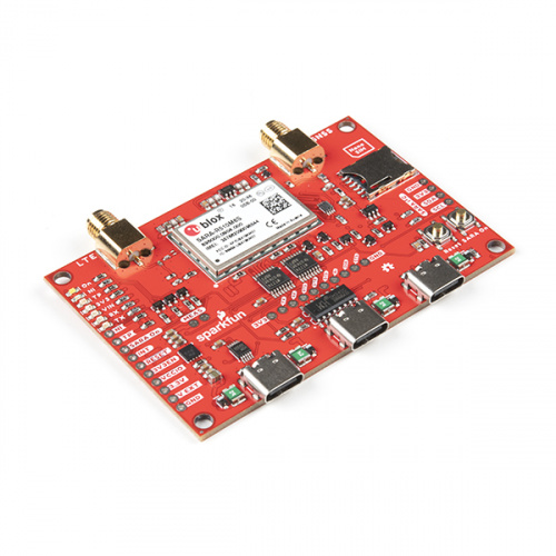
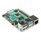
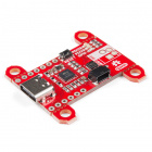
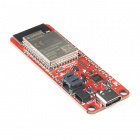
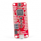
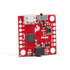
SparkFun has paired up with CircuitDojo to bring you the SparkFun nRF9160 Thing Plus, which features the powerful Nordic nRF9160 microcontroller in a feather-compatible footprint. This little chip is capable of both CAT M1 LTE and NB-IoT cellular communication and is designed to work with Zephyr, the go-to RTOS for embedded development.
Not only can you take advantage of Nordic’s advanced power states, but you can also put the device into a low power standby state. Laboratory measurements are putting that mode at about 2µA of current. 2µA! It also features a 3.3V Buck-Boost which helps get every mWh from your batteries as possible.
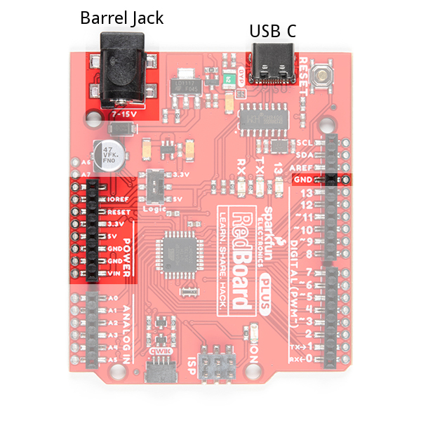
No batteries? No problem! You can plug or power your nRF9160 Thing Plus externally for AC/DC powered operation. Keep it on at all times for high availability scenarios. Power it via the 5V pin or insert a USB C cable to keep things going.
Want to persist data? The nRF9160 Thing Plus has a 4MB external flash for storing data while offline. Using external flash with a filesystem like LitteFS and you’ll have a project to recon with!
In stock
WRL-17354
SparkFun has teamed up with CircuitDojo to bring you the nRF9160 Thing Plus, featuring the powerful Nordic nRF9160 in a Feath…
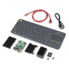
Required Materials
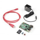
To follow along with this tutorial, you will need the following materials. You may not need everything though depending on what you have. Add it to your cart, read through the guide, and adjust the cart as necessary.
Suggested Reading
We would also recommend taking a look at the following tutorials if you aren't familiar with the content covered in them.
I2C
An introduction to I2C, one of the main embedded communications protocols in use today.
Hardware Overview
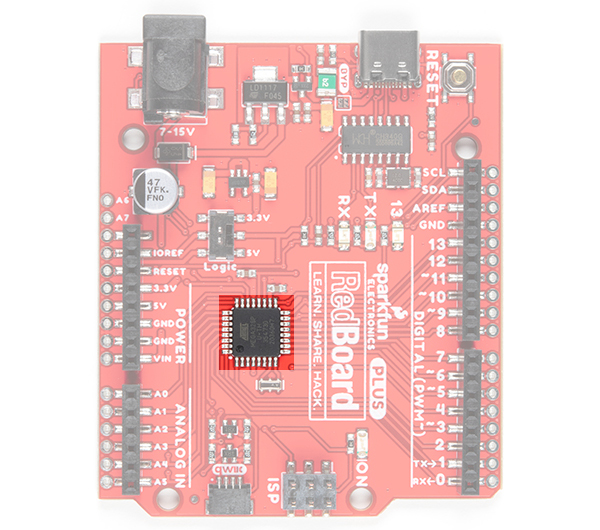
nRF9160
The nRF9160 from Nordic Semiconductor has some amazing capabilities. Some of the more prominent features are listed below. See the datasheet for more information.
- Microcontroller
- ARM Cortex M33
- 1MB Flash
- 256kB RAM
- ARM® TrustZone®
- ARM® Cryptocell 310
- Up to 4x SPI, I2C and UART with Easy DMA
- I2S w/ EasyDMA
- 4x PWM with EasyDMA
- 12bit SADC with EasyDMA
- 2x RTC
- PPI (Programmable peripheral interconnect) interface
- Radio
- Transceiver and baseband
- 3GPP LTE release 13 Category M1 and NB1 compliant
- 3GPP release 14 NB2 compliant
- GPS receiver (GPS L1 C/A supported) - Active antenna only.
- RF Transceiver for global coverage supporting bands:
- Cat-M1: B1, B2, B3, B4, B5, B8, B12, B13, B14, B17, B18, B19, B20, B25, B26, B28, B66
- Cat-NB1/NB2: B1, B2, B3, B4, B5, B8, B12, B13, B17, B18, B20, B25, B26, B28, B66
- Supports 4FF Nano SIM
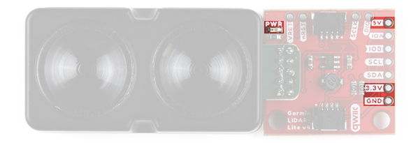
Power
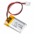
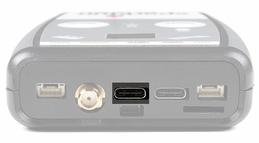
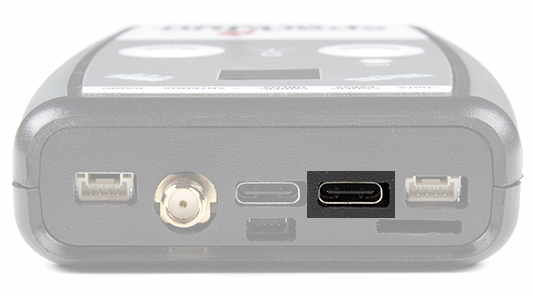
The nRF9160 Thing Plus has an operating range of 2.8V to 5.5V and can be powered several ways. The most popular way to power Thing Plus boards is by using the USB C port on the bottom of the board. Alternatively, the board can be powered by a LiPo battery plugged into the 2 pin JST connector on the left side.
⚡
NOTE: The nRF9160 shouldn't be used with a battery less than 300mAH.
The board is designed from the ground up to be power efficient at the most used power state: standby. As of this writing the estimated current draw in this state should be about 2µA.
In addition, the nRF9160 Thing Plus also has a fully fledged DC/DC Buck Boost. That way, whether your input voltage is 5.5 or 2.8V you'll get a nice stable 3.3V at the output.
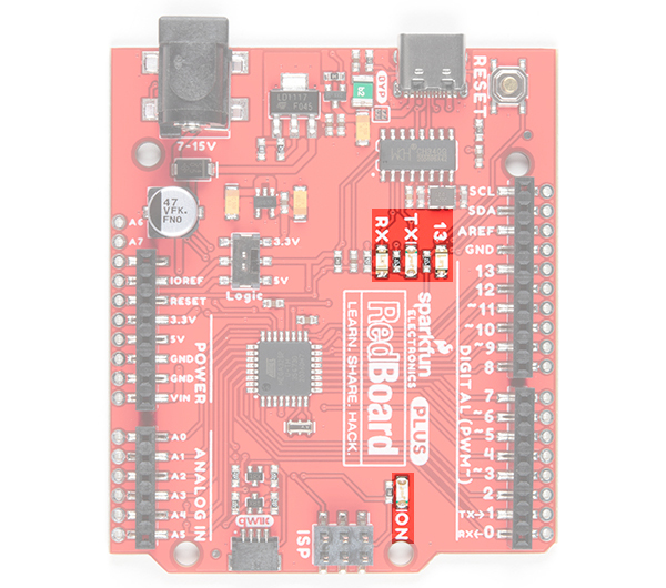
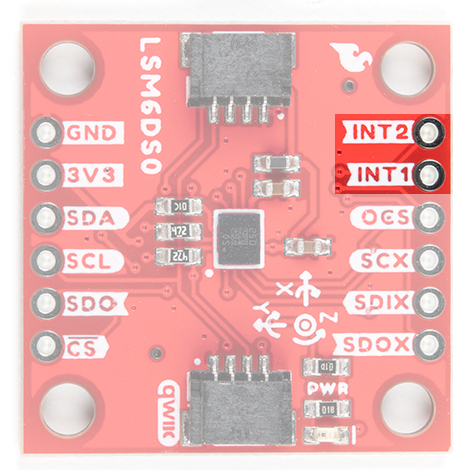
JTAG
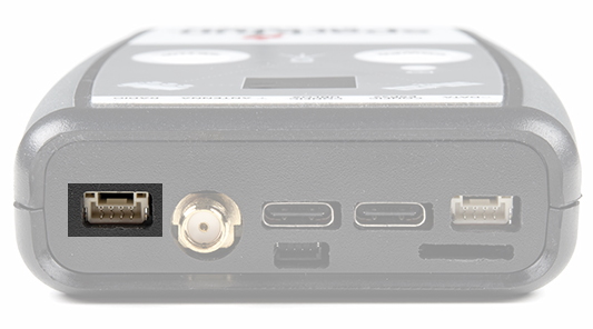
If you choose to use an external programmer, the JTAG pins highlighted here will allow you to connect. We recommend the nRF5340DK or, for non-commercial use, we recommend the J-Link EDU Mini Programmer.
Sim Card
In order to use the LTE functionality, you'll need to activate and insert the included Hologram Sim Card. Head over to Hologram's Start Page and follow the instructions to activate your card. In this tutorial, we are using the most basic license, which is free (up to a point).
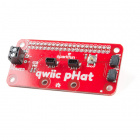
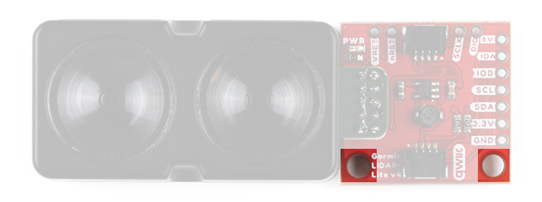
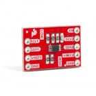
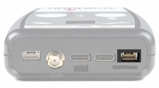
Qwiic Connector
Our Qwiic Ecosystem makes using qwiic sensors pretty much plug and play. Use this port to attach your sensor of choice!
Buttons
In order to upload code to the nRF9160 Thing Plus, you'll need to put the board in Bootloader mode. To do so, do the following:
- Press the Mode button (MD)
- While holding down the Mode button, press and release the Reset (RST) button.
- When the LED lights up, release the Mode button
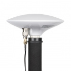
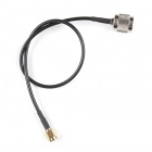
Antenna Connections
There are two antenna connectors - one U.FL for the LTE with matching network, one U.FL for active GPS antennas (active only). The connectors are labelled on the back of the board to help you remember which is which.
- Antenna supply voltage: 3.3V± 0.3V
- Antenna current rating: 15mA
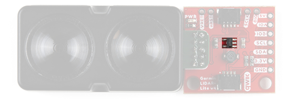
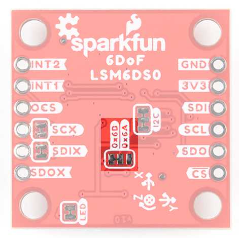
Jumpers
There are two jumpers on the board.
JMP1 is used to disable the accelerometer interrupt on Pin 2. By default, the interrupt is push/pull and is always enabled. To disable, cut the trace.
JMP2 is used to disable PS_EN's connection to the power supply, which allows you to use PS_EN as a GPIO pin. You can turn this functionality to "Always on" operation by shorting the middle and right pads on JMP2 and cutting the existing short.
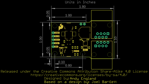
Board Dimensions
The nRF9160 Thing Plus measures 2.10 inches by 0.9 inches.
SDK Setup - Windows
This page is all about getting your Windows machine compiling code for the nRF9160 Thing Plus. Run into trouble during the process? Post your questions on the community forum.
IDE Setup
Install or use the code editor of your choice. I personally use Microsoft Visual Studio Code. The download link is here, or you can download by clicking the button below. If you decide to use Visual Studio Code, make sure you install the C/C++ and Cortex-Debug extentions using the built in extension marketplace.
SDK Install
nRF Connect For Desktop is the utility that you can use to manipulate your nRF9160 Thing Plus. Download and install nRF Connect For Desktop.
Once downloaded, run the installer:
Open up the app and install the Toolchain Manager:
Open up the Toolchain Manager after installing. Scroll to the bottom and click Install package from other source
Then paste this url into the box and click ok:
language:c
http://developer.nordicsemi.com/.pc-tools/toolchain/ncs-toolchain-v1.4.1-20201215-7ecf886-minimal.zip
The download and install will take a few minutes. Hang out, take a walk, sing a song, and come back later.
Once installed you'll have a dropdown that you can access. Click on it and then the Open Bash or Open Command Prompt option. (I prefer bash since I use *nix a lot)
To get the nRF9160 Thing Plus examples we'll update C:\Users\<your username>\ncs\v1.4.1\nrf\west.yml. First in the remotes section add:
language:c
name: circuitdojo
url-base: https://github.com/circuitdojo
Then in the projects section add at the bottom:
language:c
name: nfed
repo-path: nrf9160-feather-examples-and-drivers
revision: v1.4.x
path: nfed
remote: circuitdojo
Then run west update in your freshly created bash/command prompt session. This will fetch the nRF9160 Thing Plus examples.
Installing newtmgr
newtmgr is required for the MCU bootloader to work. You can download the binary file here or by clicking the button below:
Extract it and move it into your C:\Users\<your username>\ncs\v1.4.1\toolchain\bin directory.
Add the path to your newtmgr.exe to your system $PATH. If you're unfamiliar with the process check out
this guide. Also remember to restart your bash window after updating the system $PATH.
Setting your connection configuration (one time only)
In order to easily work with newtmgr you'll need to make a one-time connection profile. Make sure that the COM port matches the one attached to the nRF9160 Thing Plus. An easy way to check is to remove and add the device to see which COM port shows up in device manager.
language:c
newtmgr conn add serial type=serial connstring="dev=COM3,baud=1000000"
You've now created a connection called serial. We'll be using that when issuing commands to the nRF9160 Thing Plus.
SDK Setup - Mac
This page is all about getting your Mac compiling code for the nRF9160 Thing Plus. Run into trouble during the process? Post your questions on the community forum.
IDE Setup
Install or use the code editor of your choice. I personally use Microsoft Visual Studio Code. The download link is here or you can download by clicking the button below. If you decide to use Visual Studio Code, make sure you install the C/C++ and Cortex-Debug extentions using the built in extension marketplace.
Installing SDK
Installing the latest SDK is a snap and only takes a few steps. Let's walk through them here.
nRF Connect For Desktop is the utility that you can use to manipulate your nRF9160 Thing Plus. Download and install nRF Connect For Desktop.
Copy the app to your Applications folder
Open up the app and install the Toolchain Manager
Then open it up.
Scroll to the bottom and click Install package from other source:
Then paste this url into the box and click OK:
language:c
http://developer.nordicsemi.com/.pc-tools/toolchain/ncs-toolchain-v1.5.0-20210225-607a0e0-minimal.dmg
The download and install will take a few minutes. Hang out, take a walk, sing a song, and come back later.
Finally, once installed you'll have a dropdown that you can access. Click on it and then the Open Terminal option.
To get the nRF9160 Thing Plus examples we'll update /opt/nordic/ncs/v1.4.1/nrf/west.yml.
First in the remotes section add:
language:c
name: circuitdojo
url-base: https://github.com/circuitdojo
Then in the projects section add at the bottom:
language:c
name: nfed
repo-path: nrf9160-feather-examples-and-drivers
revision: v1.4.x
path: nfed
remote: circuitdojo
Then run west update in your freshly created terminal session. This will fetch the nRF9160 Thing Plus examples.
Installing newtmgr
If you're on a newer version of OSX you'll need to install the drivers.
For loading code to your nRF9160 Thing Plus, you'll need to download and copy a custom version of newtmgr. Open a terminal window and run:
language:c
cd ~/Downloads
wget "https://docs.jaredwolff.com/files/newtmgr/darwin/newtmgr.zip"
unzip newtmgr.zip
mv newtmgr /opt/nordic/ncs/v1.4.1/toolchain/bin
rm newtmgr.zip
Then you'll need to add your serial profile to make it easier to download/update your device:
language:c
newtmgr conn add serial type=serial connstring='dev=/dev/tty.SLAB_USBtoUART,baud=1000000'
If you have multiple Silicon Labs CP2102 connected to your machine your serial port may be named differently. I recommend you unplug all devices that could be named tty.SLAB_USBtoUART to ensure you're targeting the correct device during programming.
For more info in using newtmgr checkout the programming section.
Now you can get to playing around with some of the nRF9160 Thing Plus example code! Remember you'll always have to open a terminal using the Toolchain Manager to build code!
SDK Setup - Linux/Ubuntu
This page is all about getting your Linux machine compiling code for the nRF9160 Thing Plus. Run into trouble during the process? Post your questions on the community forum.
Installing IDE
Install or use the code editor of your choice. I personally use Microsoft Visual Studio Code. You can download directly from the Ubuntu Software Install utility.
If you decide to use Visual Studio Code, make sure you install the C/C++ and Cortex-Debug extentions using the built in extension marketplace.
Installing SDK
Install dependencies using apt-get
language:bash
sudo apt install --no-install-recommends git cmake ninja-build gperf \
ccache dfu-util device-tree-compiler wget \
python3-dev python3-pip python3-setuptools python3-tk python3-wheel xz-utils file \
make gcc gcc-multilib g++-multilib libsdl2-dev
Check your cmake version:
language:bash
cmake --version
If it's older than 3.13.3, you'll have to install a newer version using the instructions here.
Install west. West is the most important utility for using nRF Connect SDK & Zephyr.
language:bash
pip3 install --user -U west
Then make sure that ~/.local/bin is added to your path:
language:bash
echo 'export PATH=~/.local/bin:"$PATH"' >> ~/.bashrc
source ~/.bashrc
Now create a folder on your machine and call it nfed (short for nRF9160 Feather Examples and Drivers). Open a terminal to this folder and initialize nRF Connect SDK using west:
language:bash
cd ~
mkdir nfed
cd nfed
west init -m https://github.com/circuitdojo/nrf9160-feather-examples-and-drivers --mr main
Once your nRF Connect SDK compontents are downloaded, you'll need to fetch the remaining SDK:
language:bash
west update
You'll see a bunch of output go by as west downloads dependencies using Git.
Here's what your nfed folder should look like:
❯ tree -L 1
.
├── bootloader
├── build
├── latest
├── mbedtls
├── modules
├── nrf
├── nrf9160-feather
├── nrfxlib
├── test
├── tools
└── zephyr
Installing the remaining SDK requirements using pip3:
language:bash
pip3 install --user -r zephyr/scripts/requirements.txt
pip3 install --user -r nrf/scripts/requirements.txt
pip3 install --user -r bootloader/mcuboot/scripts/requirements.txt
Note: there may be an error during the first pip3 install. You can safely ignore them.
Note: nRF Connect for Desktop is distributed as an
appimage. Right click and enable running as an executable. Then you can double click and run as any other app.
![nRF Desktop AppImage]()
![nRF Desktop Allow as Executable]()
The ARM Embedded Toolchain
First download the latest Zephyr SDK installer:
language:bash
cd ~
wget https://github.com/zephyrproject-rtos/sdk-ng/releases/download/v0.11.4/zephyr-sdk-0.11.4-setup.run
Then run it:
language:bash
chmod +x zephyr-sdk-0.11.4-setup.run
./zephyr-sdk-0.11.4-setup.run -- -d ~/zephyr-sdk-0.11.4
Finally install the udev rules which allows you to flash boards using a programmer.
language:bash
sudo cp ~/zephyr-sdk-0.11.4/sysroots/x86_64-pokysdk-linux/usr/share/openocd/contrib/60-openocd.rules /etc/udev/rules.d
sudo udevadm control --reload
Installing newtmgr
For loading code to your nRF9160 Thing Plus, you'll need to download and copy a custom version of newtmgr to a folder in your PATH.
language:bash
cd ~/Downloads
wget "https://docs.jaredwolff.com/files/newtmgr/linux/newtmgr.zip"
unzip newtmgr.zip
mv newtmgr ~/.local/bin
rm newtmgr.zip
If you're not sure, ~/.local/bin is always a good spot for these types of binaries.
Then you'll need to add your serial profile to make it easier to download/update your device:
language:bash
newtmgr conn add serial type=serial connstring='dev=/dev/ttyUSB0,baud=1000000'
newtmgr -c serial reset
If you have multiple Silicon Labs CP2102 connected to your machine your serial port may be named differently. I recommend you unplug all devices that could be named ttyUSB0 to ensure you're targeting the correct device during programming.
Note if you get a Error: open /dev/ttyUSB0: permission denied error. You'll have to fix permissions for the serial device for all users. Here are the steps:
Open this .rules file in vi (or your editor of choice):
language:bash
sudo vi /etc/udev/rules.d/50-myusb.rules
Then within the editor hit i, paste this:
language:bash
KERNEL=="ttyUSB[0-9]*",MODE="0666"
KERNEL=="ttyACM[0-9]*",MODE="0666"
Hit the esc button and then type :wq!.
For more info in using newtmgr checkout the programming section of CircuitDojo's documentation.
Programming and Debugging
There are currently two ways of programming the nRF9160 Thing Plus. You can use the built-in bootloader or use an external programmer.
Bootloader
Currently the nRF9160 Thing Plus uses the MCUBoot bootloader which comes standard with the nRF Connect SDK. It is the recommended way to load new firmware onto your nRF9160 Thing Plus.
In order to utilize the bootloader, you'll need to make sure you have
newtmgr (AKA
mcumgr) installed. Instructions for your platform can be found in the SDK Setup sections of this tutorial.
Pre-check: MCUBoot needs to be enabled in your project before you can use it! Make sure that you have CONFIG_BOOTLOADER_MCUBOOT=y in your prj.conf.
Put your nRF9160 Thing Plus into DFU mode.
- Press the Mode button (MD)
- While holding down the Mode button, press and release the Reset (RST) button.
- When the LED lights up, release the Mode button
Build your application if you haven't already with west build. It will create a folder called build. The file we care about is build/zephyr/app_update.bin
Load the file using newtmgr
- Load the binary file using: newtmgr -c serial image upload build/zephyr/app_update.bin
- Reset your board using newtmgr -c serial reset or hit the RST button. Full process below:
Note:
The transfer process is limited to 1M BAUD. In most cases it takes about 8 seconds to transfer application code.
The nRF9160 Thing Plus does not respond to newtmgr commands unless it's in DFU mode. (See the above to get it into DFU mode.)
External Programming and Debugging
You can also use external programmers with the nRF9160 Thing Plus. Here are the current supported external programmers:
Note: Most commercial J-Link programmers *should* work with the nRF9160 Thing Plus. In particular the
J-Link EDU Mini is a great choice if you're building non-commercial products. (Supports Cortex M33 processors. Untested at this time.)
Important: The nRF52 and nRF51 based development kits do not work with the nRF9160 Thing Plus!
Installing programmer software
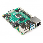
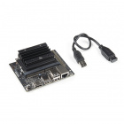
The nRF5340-DK is the programmer of choice. These steps should not be different from other J-Link supported boards.
Download your version of the nRF Command Line Tools.
- Windows
- Then, run the .exe that was downloaded. It will do all the heavy lifting for you.
- Run nrfjprog in a cmd window to make sure your install is working.
- You may also have to add JLink.exe to your path. It's the exact same procedure as adding newtmgr except the path you're adding is C:\Program Files (x86)\SEGGER\JLink.
- Close/restart VSCode and your Command Prompt
- Run jlink.exe and make sure it opens.
- Mac:
- First run nRF-Command-Line-Tools_10_9_0_OSX.pkg
- Once that install is done, run JLink_MacOSX_V680a.pkg
- Open a fresh terminal window and run nrfjprog and jlinkexe to make sure your install is complete.
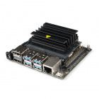
Setting up the nRF5340-DK
Here are a couple of close up shots of how to connect the nRF5340-DK:
I highly recommend you jump SB47 on your nRF5340-DK with some solder. This forces the debugger to think an external devices is permanently connected. If you're only doing external debugging, this is very useful.
After hooking things up, It's time to do a quick smoke test. Running nrfjprog -r in a terminal should show this result:
language:bash
$ nrfjprog -r
Applying system reset.
Run.
Success!
Programming with the nRF5340-DK
Programming with the nRF5340-DK is straight forward in Zephyr using west. Here's what it looks like:
language:bash
west build -b circuitdojo_feather_nrf9160ns -p
west flash --runner nrfjprog
nrfjprog -r
In the above, I'm:
- Doing a pristine build of my application with the nRF9160 Thing Plus as the target.
- Then flashing using the nrfjprog runner option. This is preferred for all J-Link boards.
- Resetting the board using nrfjprog -r. As of this writing, west does not reset the board after programming.
Getting a Modem Trace
Sometimes, you may be requested to get a modem trace of your device. This section will focus on helping you get one for your nRF9160 Thing Plus.
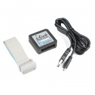
In order to get a modem trace, the TX and RX pins on your board need to be free. You'll also need a UART to USB adapter of some type. I used an FTDI one that has each of the lines broken out.
First, set your prj.conf to include the following lines:
language:bash
# Enable modem trace
CONFIG_BSD_LIBRARY_TRACE_ENABLED=y


# AT host library
CONFIG_UART_INTERRUPT_DRIVEN=y
CONFIG_AT_HOST_LIBRARY=y
Note: Version v1.5.x and newer uses this flag to enable modem tracing: CONFIG_NRF_MODEM_LIB_TRACE_ENABLED=y
Then, create a folder in your project/sample called boards and add a new file called circuitdojo_feather_nrf9160ns.overlay We'll want to enable the UART1 interface on pins 23 and 24 like below:
language:bash
/*
* Copyright (c) 2020 Circuit Dojo LLC
*
* SPDX-License-Identifier: Apache-2.0
*/

&uart1 {
status = "okay";
current-speed = <115200>;
tx-pin = <24>;
rx-pin = <23>;
};
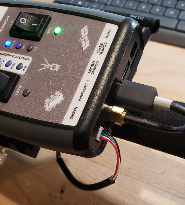
Connect your USB to UART adapter. I've used clips from my logic analyzer to hold the wires in place. Connect the yellow wire to the TX on the board. Connect the orange wire to the RX on the board.
Image courtesy of CircuitDojo
Then open the serial port in the modem trace app and click start.
Click on the image for a closer view
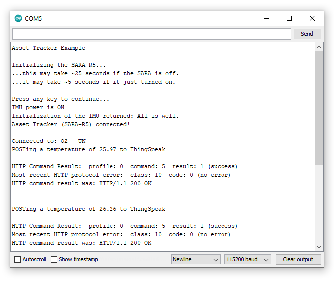
Then run your app as normal. You should see the Trace size go up little by little as connections are made, etc.
Click on the image for a closer view
Then grab the file according to the log output. For example: Tracefile created: /Users/jaredwolff/Library/Application Support/nrfconnect/pc-nrfconnect-tracecollector/trace-2020-09-16T20-47-19.741Z.bin
For more information, check out Nordic's original article on the subject.
Debugging in Visual Studio Code
Debugging your application is possible with Visual Code. If you get a J-Link programmer such as the J-Link EDU Mini Programmer, it will include the necessary cabling. Programmers that are possible include the nRF9160 DK, nRF532 DK, J-Link EDU (if your project is non-profit) and the standard commercial J-Link programmers.
Here's the process:
Download and install your version of the nRF Command Line Tools.
Install the C/C++ Extension and the Cortex-Debug extensions. They're both very handy in development and debugging of Zephyr based projects.
If you don't have one already, create a .vscode folder in the root of your project.
Create a file called launch.json. This is where we'll set up the configuration for debugging.
Here's a real example of a config I was using to debug a project in OSX:
{
  // Use IntelliSense to learn about possible attributes.
  // Hover to view descriptions of existing attributes.
  // For more information, visit: https://go.microsoft.com/fwlink/?linkid=830387
  "version": "0.2.0",
  "configurations": [
    {
      "name": "Cortex Debug",
      "cwd": "${workspaceRoot}",
      "executable": "${workspaceRoot}/pyrinas/applications/dreamstars/build/zephyr/zephyr.elf",
      "request": "launch",
      "type": "cortex-debug",
      "servertype": "jlink",
      "device": "nrf9160_xxAA",
      "interface": "swd",
      "armToolchainPath": "/Users/jaredwolff/gcc-arm-none-eabi-9-2019-q4-major/bin"
    }
  ]
}
For folks on Windows you'll have to modify appropriately:
{
 // Use IntelliSense to learn about possible attributes.
 // Hover to view descriptions of existing attributes.
 // For more information, visit: https://go.microsoft.com/fwlink/?linkid=830387
 "version": "0.2.0",
 "configurations": [
    {
        "name": "Cortex Debug",
        "cwd": "${workspaceRoot}",
        "executable": "${workspaceRoot}\\nrf9160-feather\\samples\\blinky\\build\\zephyr\\zephyr.elf",
        "request": "launch",
        "type": "cortex-debug",
        "servertype": "jlink",
        "device": "nrf9160_xxAA",
        "interface": "swd",
        "armToolchainPath": "C:\\Program Files (x86)\\GNU Tools Arm Embedded\\9 2019-q4-major\\bin"
    }
 ]
}
Remember that workspaceRoot refers to the folder you have opened in VSCode. This will most likely be /opt/nordic/ncs/v1.4.1/nfed or c:\users\<user name>\ncs\v1.4.1\nfed. You will have to modify the "executable" entry to match the path of your zephyr.elf file.
Change the executable path and the armToolchainPath to reflect your system. Make sure you point the executable option to the .elf file that gets produced during the compilation process.
Next, go to your projects prj.conf and disable the bootloader by commenting outCONFIG_BOOTLOADER_MCUBOOT=y or changing the y to a n. As of this writing, disabling the bootloader is required as it prevents the debugging process from occuring.
In prj.conf you'll also want to enable the CONFIG_DEBUG option. This disables compiler optimizations which make the debug process hairy and/or impossible.
Finally, program your project using west build&& west flash.
At this point, if you've ever done any debugging in Visual Code, you should be able to follow the final steps to debug your application!
Set some breakpoints in your code by pressing the line number you want. A red dot will appear where the breakpoint is set.
Start debugging by clicking the debug icon on the left. Then click the play button in the top left.
You can use the popup menu on the right to control traversal through your code.
Compiling an Application
Prerequisites/SDK Setup
If you haven't already, make sure you've set up the SDK:
General Build Commands
Generally speaking, as long as you have all the requirements from the guide above, compiling for the nRF9160 Thing Plus should be as simple as running the following:
language:bash
west build -b circuitdojo_feather_nrf9160ns
If you would like to "clean" your project before building add the -p parameter.
language:bash
west build -b circuitdojo_feather_nrf9160ns -p
The output assets are placed in the build/zephyr folder. If you're programming from scratch, you'll want the merged.hex. If you're using newtmgr then you'll want the app_update.bin. More info on different programming methods can be found in the Programming and Debugging section.
For subsequent builds you don't need -b circuitdojo_feather_nrf9160ns if you're not using the -p param.
language:bash
west build
west uses the last board that was indicated for the re-build.
Common errors and warnings
CMake complains about your MCUBoot key:

CMake Warning at /Users/jaredwolff/Git/nrf-connect/ncs/v1.4.1/nrf/cmake/mcuboot.cmake:115 (message):


        ---------------------------------------------------------
        --- WARNING: Using default MCUBoot key, it should not ---
        --- be used for production.                           ---
        ---------------------------------------------------------
The default bootloader uses the default MCUBoot key. Before you compile your project, make sure that the following lines are added to the prj.conf:
language:bash
# Enable Zephyr application to be booted by MCUboot
CONFIG_BOOTLOADER_MCUBOOT=y
This will enable support for the bootloader.
Example - Blinky
Let's start with a basic example and move up from there!
Change directories to ncs/v1.4.1/zephyr/samples/basic/blinky.
Make sure you've enabled support for the bootloader by verifying that the following lines are added to the prj.conf:
language:bash
# Enable Zephyr application to be booted by MCUboot
CONFIG_BOOTLOADER_MCUBOOT=y
Then, build using the build command:
language:bash
west build -b circuitdojo_feather_nrf9160ns
You should see towards the end of the output that both the application and the bootloader have been built and merged.
Uploading Code
Make sure that you have set your connection configuration (this should only need to be done once) and put your nRF9160 into Boot mode.
- Press the Mode button (MD)
- While holding down the Mode button, press and release the Reset (RST) button.
- When the LED lights up, release the Mode button
Programming can then be completed with newtmgr by pasting the following into your bash/terminal window:
language:bash
newtmgr -c serial image upload build/zephyr/app_update.bin
newtmgr -c serial reset
Notes:
The transfer process is limited to 1M BAUD. In most cases it takes about 8 seconds to transfer application code.
Reminder: The nRF9160 Thing Plus does not respond to newtmgr commands unless it's in DFU mode.
Example - AT Client Sample
Change directories to ncs/v1.4.1/nrf/samples/nrf9160/at_client.
Make sure that the following lines are added to the prj.conf:
language:bash
# Enable Zephyr application to be booted by MCUboot
CONFIG_BOOTLOADER_MCUBOOT=y
This will enable support for the bootloader. Then, build using the build command:
language:bash
west build -b circuitdojo_feather_nrf9160ns
You can see towards the end of this output that both the application and the bootloader have been built and merged.
Uploading Code
Make sure that you have set your connection configuration (this should only need to be done once) and put your nRF9160 into Boot mode.
- Press the Mode button (MD)
- While holding down the Mode button, press and release the Reset (RST) button.
- When the LED lights up, release the Mode button
Programming can then be completed with newtmgr by pasting the following into your bash/terminal window:
language:bash
newtmgr -c serial image upload build/zephyr/app_update.bin
newtmgr -c serial reset
Reminder: The nRF9160 Thing Plus does not respond to newtmgr commands unless it's in DFU mode.
LTE Link Monitor
The best way to debug anything cellular-related is to use the LTE Link Monitor. To install:
- (for OSX folks) If you haven't already, install the Si2102 USB-to-Serial drivers.
- Make sure you have nRF Connect For Desktop installed as outlined in the SDK sections of this tutorial
- Open up nRF Connect and in the list of apps, find LTE Link Monitor
- Click install
- Once installed click open and let the fun begin!
For more information check out Nordic's Documentation.
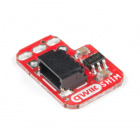
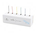
Sim Card
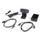
Your purchase of the Sparkfun nRF9160 Thing Plus should have included a SIM card for use with LTE applications. In this instance, we have the Hologram SIM card:
In stock
CEL-17117
The Hologram eUICC SIM Card is a mix between legacy and new technology for cellular service for your project.
In order to use the SIM card, you'll need to activate it. Go to Hologram's Start Page and follow the instructions. In this tutorial, we are using the most basic license, which is free (up to a point).
Using the LTE Link Monitor
Almost any code example can be used with the AT Host Library. Generally all that is needed is adding these lines to your prj.conf:
language:bash
# AT host library
CONFIG_AT_HOST_LIBRARY=y
CONFIG_UART_INTERRUPT_DRIVEN=y
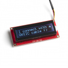
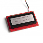
Alternatively, for a quick start, simply program the at_client example to your nRF9160 Thing Plus. Then follow these quick steps to get up an running:
- Insert your SIM into the nRF9160 Thing Plus.
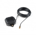
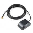
- Attach your LTE antenna.
- Plug your nRF9160 Thing Plus into your computer's USB port.
- Ensure that Flow Control is turned off, and Auto device/port filter is also unchecked.
Connect to it using the Device dropdown in the top left hand corner of the LTE Link Monitor. On *nix based systems, the port will show up like /dev/tty.SLAB_USBtoUART. On Windows, you'll have to determine which COM port is associated by using the device manager.
With Automatic requests turned on and the nRF9160 Thing Plus connected, press the AT+CFUN=1 button followed by the AT+CFUN? button. This will cause a few important commands to be automatically sent to your nRF9160 Thing Plus. Additionally, your nRF9160 Thing Plus will attempt to connect to the closest compatible tower possible.
Review the LTE Link Monitor for connection information.
Yes, the LTE Link Monitor provides some great information. Consider it your go-to tool when debugging cellular or board related issues.
Example - nRF Cloud AGPS Sample
The nrf_cloud_agps sample is the easiest way to get started with generating GPS coordinates with your nRF9160 Thing Plus.
Programming nrf_cloud_apgs Sample
Change directories to ncs/v1.4.1/nrf (Make sure you're using NCS v1.4.0 or newer). Then change directories to /nrf/samples/nrf9160/agps/. Add the following to prj.conf:
language:bash
# Cloud prefix for nRF9160 Thing Plus
CONFIG_NRF_CLOUD_CLIENT_ID_PREFIX="thing-plus-"

# Enable Zephyr application to be booted by MCUboot
CONFIG_BOOTLOADER_MCUBOOT=y

# COEX0 is used to enable the GPS LNA, but it has to be configured to do so.
CONFIG_NRF9160_GPS_SET_COEX0=y
CONFIG_NRF9160_GPS_COEX0_STRING="AT%XCOEX0=1,1,1565,1586"
Then compile as normal:
language:bash
west build -b circuitdojo_feather_nrf9160ns
Uploading Code
Make sure that you have set your connection configuration (this should only need to be done once) and put your nRF9160 into Boot mode.
- Press the Mode button (MD)
- While holding down the Mode button, press and release the Reset (RST) button.
- When the LED lights up, release the Mode button
Programming can then be completed with newtmgr by pasting the following into your bash/terminal window:
language:bash
newtmgr -c serial image upload build/zephyr/app_update.bin
newtmgr -c serial reset
Reminder: The nRF9160 Thing Plus does not respond to newtmgr commands unless it's in DFU mode.
Setting Up nRF Connect for Cloud
Note: Some of these steps take time to complete and/or register with the cloud devices. Be patient!
During factory test, your nRF9160 Thing Plus is added to nRF Connect for Cloud for your immediate use. The boards are registered with an nRF cloud key of 7753 (SPKF). You'll use this, along with your nRF9160 Thing Plus, SIM and antenna to connect to the nRF Connect for Cloud and get GPS readings.
Every nRF9160 Thing Plus has a device ID generated based on the IMEI. Your full device ID will look something like:
thing-plus-<IMEI> where <IMEI> is the IMEI tied to your specific device. You'll need this in a moment.
Above you should have compiled and programmed your device with the nrf_cloud_agps sample. Power up and confirm that the device can connect to the cloud. Then pop on over to your favorite internet browser, go to nrfcloud.com, and create an nRF Connect for Cloud Account.
Once created, go to the top left and click the big + icon.
Add new:
Then skip the iBasis setup since we're using Hologram.
Enter the Device ID and the PIN.
Once you press Add Device, nRF Connect for Cloud should notify you that your device has been added. Navigate to Devices and click on the device you're working with!
That's it! Your device screen will adapt to whatever example code that you're using.
Troubleshooting
There are some things that can go wrong here. They're usually related to your nRF Cloud certs.
Reloading the certs can be done using the tutorial here.
Debug Serial Usage
The nRF9160 Thing Plus comes with an on-board Silicon Labs CP2102 USB-to-UART chip. You can use it with most serial terminal viewers. If you have an older version of Windows you will have to install the driver. The download is located here.
Here are some recommendations for software to communicate with the nRF9160 Thing Plus. No matter what program you use, the standard baud rate for the console is 115200. All other options are standard/default (8 bits, oon-parity, 1 stop bit).
Multi-Platform
nRF Connect For Desktop - LTE Link Monitor
If you haven't already, make sure you check out the LTE Link Monitor. It's a great multi-purpose tool for using and debugging the nRF9160 Thing Plus.
CoolTerm
CoolTerm has been my go-to for testing and debugging. Fortunately it's also multi-platform! The download is located here.
Mac OSX & Linux
screen
You can use
screen to view your debug output. Here's a typical command:
language:bash
screen /dev/tty.SLAB_USBtoUART 115200
The major drawback of using
screen is that it does not save your history. It's better to use other utilities for that purpose.
Note: depending on your system your serial port may be named something different from
/dev/tty.SLAB_USBtoUART. You can check your dev folder like this to check which one may be it:
language:bash
ls -l /dev | grep SLAB
cu
You can also use cu to display your debug output. Here's an example:
language:bash
sudo cu -l /dev/tty.SLAB_USBtoUART -s 115200
If you notice, it requires super user permissions. (This is the only drawback to it IMHO)
To escape from your session type ~.
Troubleshooting
Not working as expected and need help?
If you need technical assistance or more information on the nRF9160 Thing Plus, your best option is to head to the
Community Forum over at CircuitDojo. They have a great collection of troubleshooting resources as well as a community dedicated to the nRF9160.
You can also take a look at the
SparkFun Technical Assistance page for some initial troubleshooting.
If you don't find what you need there, the
SparkFun Forums are a great place to find and ask for help. If this is your first visit, you'll need to
create a Forum Account to search product forums and post questions.
Resources and Going Further
For more information, check out the resources below:
Circuit Dojo information:
Nordic Semiconductor:
Check out these related tutorials:
learn.sparkfun.com |
CC BY-SA 3.0
| SparkFun Electronics | Niwot, Colorado


](http://cdn.sparkfun.com/assets/learn_tutorials/1/8/5/7/SparkFun_RTK_Express_-_Logging_Menu.jpg)