Quantcast
Channel: SparkFun Tutorials
Viewing all 1123 articles
Browse latest View live

Alternating Current (AC) vs. Direct Current (DC)

$
0
0

Alternating Current (AC) vs. Direct Current (DC) a learn.sparkfun.com tutorial

Thunderstruck!

alt text

Where did the Australian rock band AC/DC get their name from? Why, Alternating Current and Direct Current, of course! Both AC and DC describe types of current flow in a circuit. In direct current (DC), the electric charge (current) only flows in one direction. Electric charge in alternating current (AC), on the other hand, changes direction periodically. The voltage in AC circuits also periodically reverses because the current changes direction.

Most of the digital electronics that you build will use DC. However, it is important to understand some AC concepts. Most homes are wired for AC, so if you plan to connect your Tardis music box project to an outlet, you will need to convert AC to DC. AC also has some useful properties, such as being able to convert voltage levels with a single component (a transformer), which is why AC was chosen as the primary means to transmit electricity over long distances.

What You Will Learn

  • The history behind AC and DC
  • Different ways to generate AC and DC
  • Some examples of AC and DC applications

Recommended Reading

Alternating Current (AC)

Alternating current describes the flow of charge that changes direction periodically. As a result, the voltage level also reverses along with the current. AC is used to deliver power to houses, office buildings, etc.

Generating AC

AC can be produced using a device called an alternator. This device is a special type of electrical generator designed to produce alternating current.

A loop of wire is spun inside of a magnetic field, which induces a current along the wire. The rotation of the wire can come from any number of means: a wind turbine, a steam turbine, flowing water, and so on. Because the wire spins and enters a different magnetic polarity periodically, the voltage and current alternates on the wire. Here is a short animation showing this principle:


(Video credit: Khurram Tanvir)

Generating AC can be compared to our previous water analogy:

alt text

To generate AC in a set of water pipes, we connect a mechanical crank to a piston that moves water in the pipes back and forth (our “alternating” current). Notice that the pinched section of pipe still provides resistance to the flow of water regardless of the direction of flow.

Waveforms

AC can come in a number of forms, as long as the voltage and current are alternating. If we hook up an oscilloscope to a circuit with AC and plot its voltage over time, we might see a number of different waveforms. The most common type of AC is the sine wave. The AC in most homes and offices have an oscillating voltage that produces a sine wave.

alt text

Other common forms of AC include the square wave and the triangle wave:

alt text

Square waves are often used in digital and switching electronics to test their operation.

alt text

Triangle waves are found in sound synthesis and are useful for testing linear electronics like amplifiers.

Describing a Sine Wave

We often want to describe an AC waveform in mathematical terms. For this example, we will use the common sine wave. There are three parts to a sine wave: amplitude, frequency, and phase.

Looking at just voltage, we can describe a sine wave as the mathematical function:

alt text

V(t) is our voltage as a function of time, which means that our voltage changes as time changes. The equation to the right of the equals sign describes how the voltage changes over time.

VP is the amplitude. This describes the maximum voltage that our sine wave can reach in either direction, meaning that our voltage can be +VP volts, -VP volts, or somewhere in between.

The sin() function indicates that our voltage will be in the form of a periodic sine wave, which is a smooth oscillation around 0V.

is a constant that converts the freqency from cycles (in hertz) to angular frequnecy (radians per second).

f describes the frequency of the sine wave. This is given in the form of hertz or units per second. The frequency tells how many times a particular wave form (in this case, one cycle of our sine wave - a rise and a fall) occurs within one second.

t is our dependent variable: time (measured in seconds). As time varies, our waveform varies.

φ describes the phase of the sine wave. Phase is a measure of how shifted the waveform is with respect to time. It is often given as a number between 0 and 360 and measured in degrees. Because of the periodic nature of the sine wave, if the wave form is shifted by 360° it becomes the same waveform again, as if it was shifted by 0°. For simplicity, we sill assume that phase is 0° for the rest of this tutorial.

We can turn to our trusty outlet for a good example of how an AC waveform works. In the United States, the power provided to our homes is AC with 120V peak (amplitude) and 60Hz (frequency). We can plug these numbers into our formula to get the equation (remember that we are assuming our phase is 0):

alt text

We can use our handy graphing calculator to graph this equation. If no graphing calculator is available we can use a free online graphing program like Desmos (Note that you might have to use ‘y’ instead of ‘v’ in the equation to see the graph).

alt text

Notice that, as we predicted, the voltage rise up to 120V and down to -120V periodically. Additionally, 60 cycles of the sine wave occurs every second. If we were to measure the voltage in our outlets with an oscilloscope, this is what we would see (WARNING: do not attempt to measure the voltage in an outlet with an oscilloscope! This will likely damage the equipment).

Applications

Home and office outlets are almost always AC. This is because generating and transporting AC across long distances is relatively easy. At high voltages (over 110kV), less energy is lost in electrical power transmission. Higher voltages mean lower currents, and lower currents mean less heat generated in the power line due to resistance. AC can be converted to and from high voltages easily using transformers.

AC is also capable of powering electric motors. Motors and generators are the exact same device, but motors convert electrical energy into mechanical energy (if the shaft on a motor is spun, a voltage is generated at the terminals!). This is useful for many large appliances like dishwashers, refrigerators, and so on, which run on AC.

Direct Current (DC)

Direct current is a bit easier to understand than alternating current. Rather than oscillating back and forth, DC provides a constant voltage or current.

Generating DC

DC can be generated in a number of ways:

  • An AC generator equipped with a device called a “commutator” can produce direct current
  • Use of a device called a “rectifier” that converts AC to DC
  • Batteries provide DC, which is generated from a chemical reaction inside of the battery

Using our water analogy again, DC is similar to a tank of water with a hose at the end.

alt text

The tank can only push water one way: out the hose. Similar to our DC-producing battery, once the tank is empty, water no longer flows through the pipes.

Describing DC

DC is defined as the “unidirectional” flow of current; current only flows in one direction. Voltage and current can vary over time so long as the direction of flow does not change. To simplify things, we will assume that voltage is a constant. For example, we assume that a AA battery provides 1.5V, which can be described in mathematical terms as:

alt text

If we plot this over time, we see a constant voltage:

alt text

What does this mean? It means that we can count on most DC sources to provide a constant voltage over time. In reality, a battery will slowly lose its charge, meaning that the voltage will drop as the battery is used. For most purposes, we can assume that the voltage is constant.

Applications

Almost all electronics projects and parts for sale on SparkFun run on DC. Everything that runs off of a battery, plugs in to the wall with an AC adapter, or uses a USB cable for power relies on DC. Examples of DC electronics include:

  • Cell phones
  • The LilyPad-based D&D Dice Gauntlet
  • Flat-screen TVs (AC goes into the TV, which is converted to DC)
  • Flashlights
  • Hybrid and electric vehicles

Battle of the Currents

Almost every home and business is wired for AC. However, this was not an overnight decision. In the late 1880s, a variety of inventions across the United States and Europe led to a full-scale battle between alternating current and direct current distribution.

In 1886, Ganz Works, an electric company located in Budapest, electrified all of Rome with AC. Thomas Edison, on the other hand, had constructed 121 DC power stations in the United States by 1887. A turning point in the battle came when George Westinghouse, a famous industrialist from Pittsburg, purchased Nikola Tesla’s patents for AC motors and transmission the next year.

AC vs. DC

Edison

Thomas Edison (Image courtesy of biography.com)


In the late 1800s, DC could not be easily converted to high voltages. As a result, Edison proposed a system of small, local power plants that would power individual neighborhoods or city sections. Power was distributed using three wires from the power plant: +110 volts, 0 volts, and -110 volts. Lights and motors could be connected between either the +110V or 110V socket and 0V (neutral). 110V allowed for some voltage drop between the plant and the load (home, office, etc.).

Even though the voltage drop across the power lines was accounted for, power plants needed to be located within 1 mile of the end user. This limitation made power distribution in rural areas extremely difficult, if not impossible.


TeslaWestinghouse
Nikola Tesla (Image courtesy of wikipedia.org) George Westinghouse (Image courtesy of pbs.org)

With Tesla’s patents, Westinghouse worked to perfect the AC distribution system. Transformers provided an inexpensive method to step up the voltage of AC to several thousand volts and back down to usable levels. At higher voltages, the same power could be transmitted at much lower current, which meant less power lost due to resistance in the wires. As a result, large power plants could be located many miles away and service a greater number of people and buildings.

Edison’s Smear Campaign

Over the next few years, Edison ran a campaign to highly discourage the use of AC in the United States, which included lobbying state legislatures and spreading disinformation about AC. Edison also directed several technicians to publicly electrocute animals with AC in an attempt to show that AC was more dangerous than DC. In attempt to display these dangers, Harold P. Brown and Arthur Kennelly, employees of Edison, designed the first electric chair for the state of New York using AC.

The Rise of AC

In 1891, the International Electro-Technical Exhibition was held in Frankfurt, Germany and displayed the first long distance transmission of three-phase AC, which powered lights and motors at the exhibition. Several representatives from what would become General Electric were present and were subsequently impressed by the display. The following year, General Electric formed and began to invest in AC technology.

alt text

Edward Dean Adams Power Plant at Niagara Falls, 1896 (Image courtesy of teslasociety.com)

Westinghouse won a contract in 1893 to build a hydroelectric dam to harness the power of Niagara falls and transmit AC to Buffalo, NY. The project was completed on November 16, 1896 and AC power began to power industries in Buffalo. This milestone marked the decline of DC in the United States. While Europe would adopt an AC standard of 220-240 volts at 50 Hz, the standard in North America would become 120 volts at 60 Hz.

High-Voltage Direct Current (HVDC)

Swiss engineer René Thury used a series of motor-generators to create a high-voltage DC system in the 1880s, which could be used to transmit DC power over long distances. However, due to the high cost and maintenance of the Thury systems, HVDC was never adopted for almost a century.

With the invention of semiconductor electronics in the 1970s, economically transforming between AC and DC became possible. Specialized equipment could be used to generate high voltage DC power (some reaching 800 kV). Parts of Europe have begun to employ HVDC lines to electrically connect various countries.

HVDC lines experience less loss than equivalent AC lines over extremely long distances. Additionally, HVDC allows different AC systems (e.g. 50 Hz and 60 Hz) to be connected. Despite its advantages, HVDC systems are more costly and less reliable than the common AC systems.

In the end, Edison, Tesla, and Westinghouse may have their wishes come true. AC and DC can coexist and each serve a purpose.

Going Further

You should now have a good understanding of the differences between AC and DC. AC is easier to transform between voltage levels, which makes high-voltage transmission more feasible. DC, on the other hand, is found in almost all electronics. You should know that the two do not mix very well, and you will need to transform AC to DC if you wish to plug in most electronics into a wall outlet. With this understanding, you should be ready to tackle some more complex circuitry and concepts, even if they contain AC.

Take a look at the following tutorials when you are ready to dive deeper into the world of electronics:


learn.sparkfun.com |CC BY-SA 3.0 | SparkFun Electronics | Boulder, Colorado


Using EAGLE: Board Layout

$
0
0

Using EAGLE: Board Layout a learn.sparkfun.com tutorial

Previously on Using EAGLE

EAGLE’s board designer is where a good portion of the magic happens. It’s here where the dimensions of the board come together, parts are arranged, and connected by copper traces. In the board editor, the conceptual, idealized schematic you’ve designed becomes a precisely dimensioned and routed PCB.

In this tutorial we’ll cover every step in EAGLE PCB design: from placing parts, to routing them, to generating gerber files to send to a fab house. We’ll also go over the basics of EAGLE’s board editor, beginning with explaining how the layers in EAGLE match up to the layers of a PCB.

Create a Board From Schematic

Before starting this tutorial, read through and follow along with the Using EAGLE: Schematic tutorial (not to mention the Setting Up EAGLE tutorial before that). The schematic designed in that tutorial will be used as the foundation for the PCB designed here.

Schematic from previous tutorial

The schematic from previous tutorial, complete with an ATmega328P, barrel jack connector, LEDs, resistors, capacitors, and connectors.

To switch from the schematic editor to the related board, simply click the Generate/Switch to Board command – (on the top toolbar, or under the File menu) – which should prompt a new, board editor window to open. All of the parts you added from the schematic should be there, stacked on top of eachother, ready to be placed and routed.

Blank board created

The board and schematic editors share a few similarities, but, for the most part, they’re completely different animals. On the next page, we’ll look at the colored layers of the board editor, and see how they compare to the actual layers of a PCB.

Layers Overview

PCB composition is all about layering one material over another. The thickest, middle part of the board is a insulating substrate (usually FR4). On either side of that is a thin layer of copper, where our electric signals pass through. To insulate and protect the copper layers, we cover them with a thin layer of lacquer-like soldermask, which is what gives the PCB color (green, red, blue, etc.). Finally, to top it all off, we add a layer of ink-like silkscreen, which can add text and logos to the PCB.

PCB layers

The layers of a double-sided PCB (image from the PCB Basics tutorial).

EAGLE’s Layers

The EAGLE board designer has layers just like an actual PCB, and they overlap too. We use a palette of colors to represent the different layers. Here are the layers you’ll be working with in the board designer:

ColorLayer NameLayer NumberLayer Purpose
Top1Top layer of copper
Bottom16Bottom layer of copper
Pads17Through-hole pads. Any part of the green circle is exposed copper on both top and bottom sides of the board.
Vias18Vias. Smaller copper-filled drill holes used to route a signal from top to bottom side. These are usually covered over by soldermask. Also indicates copper on both layers.
Unrouted19Airwires. Rubber-band-like lines that show which pads need to be connected.
Dimension20Outline of the board.
tPlace21Silkscreen printed on the top side of the board.
bPlace22Silkscreen printed on the bottom side of the board.
tOrigins23Top origins, which you click to move and manipulate an individual part.
bOrigins24Origins for parts on the bottom side of the board.
/ / HatchtStop29Top stopmask. These define where soldermask should not be applied.
\ \ HatchbStop30Absent soldermask on the bottom side of the board.
Holes45Non-condcting (not a via or pad) holes. These are usually drill holes for stand-offs or for special part requirements.
tDocu51Top documentation layer. Just for reference. This might show the outline of a part, or other useful information.

To turn any layer off or on, click the “Layer Settings…” button – – and then click a layer’s number to select or de-select it. Before you start routing, make sure the layers above (aside from tStop and bStop) are visible.

Selecting From Overlapping Objects

Here’s one last tip before we get to laying our board out. This is an interface trick that trips a lot of people up. Since the board view is entirely two-dimensional, and different layers are bound to overlap, sometimes you have to do some finagling to select an object when there are others on top of it.

Normally, you use the mouse’s left-click to select an object (whether it’s a trace, via, part, etc.), but when there are two parts overlapping exactly where you’re clicking, EAGLE doesn’t know which one you want to pick up. In cases like that, EAGLE will pick one of the two overlapping objects, and ask if that’s the one you want. If it is, you have to left-click again to confirm. If you were trying to grab one of the other overlapping objects, right-click to cycle to the next part. EAGLE’s status box, in the very bottom-left of the window, provides some helpful information when you’re trying to select a part.

GIF of selecting two layered objects

For example: In the GIF above, a VCC net overlaps another named Reset. We left-click once directly where they overlap, and EAGLE asks us if we meant to select VCC. We right-click to cycle, and it asks us instead if we’d like to select Reset. Right-clicking again cycles back to VCC, and a final left-click selects that as the net we want to move.


Whew! Enough pointers, let’s lay out a PCB!

Arranging the Board

Create a Board From Schematic

If you haven’t already, click the Generate/Switch to Board icon – – in the schematic editor to create a new PCB design based on your schematic:

Blank board created

The new board file should show all of the parts from your schematic. The gold lines, called airwires, connect between pins and reflect the net connections you made on the schematic. There should also be a faint, light-gray outline of a board dimension to the right of all of the parts.

Our first job in this PCB layout will be arranging the parts, and then minimizing the area of our PCB dimension outline. PCB costs are usually related to the board size, so a smaller board is a cheaper board.

Understanding the Grid

In the schematic editor we never even looked at the grid, but in the board editor it becomes much more important. The grid should be visible in the board editor. You can adjust the granularity of the grid, by clicking on the GRID icon – . A 0.05" grid, and 0.005" alternate grid is a good size for this kind of board.

Default grid settings are good

EAGLE forces your parts, traces, and other objects to “snap” to the grid defined in the Size box. If you need finer control, hold down ALT on your keyboard to access the alternate grid, which is defined in the Alt box.

Moving Parts

Using the MOVE tool – – you can start to move parts within the dimension box. While you’re moving parts, you can rotate them by either right-clicking or changing the angle in the drop-down box near the top.

The way you arrange your parts has a huge impact on how easy or hard the next step will be. As you’re moving, rotating, and placing parts, there are some factors you should take into consideration:

  • Dont overlap parts: All of your components need some space to breathe. The green via holes need a good amount of clearance between them too. Remember those green rings are exposed copper on both sides of the board, if copper overlaps, streams will cross and short circuits will happen.
  • Minimize intersecting airwires: While you move parts, notice how the airwires move with them. Limiting criss-crossing airwires as much as you can will make routing much easier in the long run. While you’re relocating parts, hit the RATSNEST button – – to get the airwires to recalculate.
  • Part placement requirements: Some parts may require special consideration during placement. For example, you’ll probably want the insertion point of the barrel jack connector to be facing the edge of the board. And make sure that decoupling capacitor is nice and close to the IC.
  • Tighter placement means a smaller and cheaper board, but it also makes routing harder.

Below is an example of how you might lay out your board while considering those factors. We’ve minimized airwire intersections by cleverly placing the LEDs and their current-limiting resistors. Some parts are placed where they just have to go (the barrel jack, and decoupling capacitor). And the layout is relatively tight.

Parts placed

Note: The tNames layer (which isn’t visible by default) was turned on to help identify which part is which.

Adjusting the Dimension Layer

Now that the parts are placed, we’re starting to get a better idea of how the board will look. Now we just need to fix our dimension outline. You can either move the dimensions lines that are already there, or just start from scratch. Use the DELETE tool – – to erase all four of the dimension lines.

Then use the WIRE tool – (– to draw a new outline. Before you draw anything though, go up to the options bar and set the layer to 20 Dimension. Also up there, you may want to turn down the width a bit (we usually set it to 0.008").

Dimension options selected

Then, starting at the origin, draw a box around your parts. Don’t intersect the dimension layer with any holes, or they’ll be cut off! Make sure you end where you started.

Drawing the dimension layer

That’s a fine start. With the parts laid out, and the dimension adjusted, we’re ready to start routing some copper!

Routing the Board

Routing is the most fun part of this entire process. It’s like solving a puzzle! Our job will be turning each of those gold airwires into top or bottom copper traces. At the same time, you also have to make sure not to overlap two different signals.

Using the Route Tool

To draw all of our copper traces, we’ll use the ROUTE tool– – (not the WIRE tool!). After selecting the tool, there are a few options to consider on the toolbar above:

Route options

  • Layer: On a 2-layer board like this, you’ll have to choose whether you want to start routing on the top (1) or bottom (16) layer.
  • Bend Style: Usually you’ll want to use 45° angles for your routes (wire bend styles 1 and 3), but it can be fun to make loopy traces too.
  • Width: This defines how wide your copper will be. Usually 0.01" is a good default size. You shouldn’t go any smaller than 0.007" (or you’ll probably end up paying extra). Wider traces can allow for more current to safely pass through. If you need to supply 1A through a trace, it’d need to be much wider (to find out how much, exactly, use a trace width calculator).
  • Via Options: You can also set a few via characteristics here. The shape, diameter, and drill can be set, but usually the defaults (round, auto, and 0.02" respectively) are perfect.

With those all set, you start a route by left-clicking on a pin where a airwire terminates. The airwire, and connected pins will “glow”, and a red or blue line will start on the pin. You finish the trace by left-clicking again on top of the other pin the airwire connects to. Between the pins, you can left-click as much as you need to “glue” a trace down.

Animated routing

While routing it’s important to avoid two cases of overlap: copper over vias, and copper over copper. Remember that all of these copper traces are basically bare wire. If two signals overlap, they’ll short out, and neither will do what it’s supposed to.

Good and bad trace overlaps

If traces do cross each other, make sure they do so on opposite sides of the board. It’s perfectly acceptable for a trace on the top side to intersect with one on the bottom. That’s why there are two layers!

If you need more precise control over your routes, you can hold down the ALT key on your keyboard to access the alternate grid. By default, this is set to be a much more fine 0.005".

Placing Vias

Vias are really tiny drill holes that are filled with copper. We use them mid-route to move a trace from one side of the board to the other.

To place a via mid-route, first left-click in the black ether between pins to “glue” your trace down. Then you can either change the layer manually in the options bar up top, or click your middle mouse button to swap sides. And continue routing to your destination. EAGLE will automatically add a via for you.

Routing with vias

Route Clearance

Make sure you leave enough space between two different signal traces. PCB fabricators should have clearly defied minimum widths that they’ll allow between traces – probably around 0.006" for standard boards. As a good rule-of-thumb, if you don’t have enough space between two traces to fit another (not saying you should), they’re too close together.

Ripping Up Traces

Much like the WIRE tool isn’t actually used to make wires, the DELETE tool can’t actually be used to delete traces. If you need to go back and re-work a route, use the RIPUP tool – – to remove traces. This tool turns routed traces back into airwires.

You can also use UNDO and REDO to back/forward-track.

Route Away!

That’s about all the simple rules there are. Go have the time of your life solving the routing puzzle! You may want to start on the closest, easiest traces first. Or, you might want to route the important signals – like power and ground – first. Here’s an example of a fully-routed board:

Completed Layout

See if you can do a better job than that! Make your board smaller. Or try to avoid using any vias.

After you feel like the routing is done, there are a few checks we can do to make sure it’s 100% complete. We’ll cover those on the next page.

Or Use the Autorouter (Cheater!)

If you’re short on time, or having trouble solving the routing puzzle, you can try loading up EAGLE’s Autorouter – – to see if it can finish the job. Open up the autorouter, don’t worry about these other tabs for now, just click OK.

Autorouter window default

If you don’t like the job the autorouter did, you can quickly hit Undo to go back to where you were.

The autorouter won’t always be able to finish the job, so it’s still important to understand how to manually route pads (plus manual routes look much better). After running the autorouter, check the bottom-left status box to see how it did. If it says anything other than “OptimizeN: 100% finished”, you’ve still got some work to do. If your autorouter couldn’t finish the job, try turning Routing Grid down from 50mil 10mil.

There are tons of optimizations and settings to be made in the autorouter. If you want to dig deeper into the subject, consider checking out EAGLE’s manual where an entire chapter is devoted to it.

Checking for Errors

Before we package the design up and send it off to the fabrication house, there are a few tools we can use to check our design for errors.

Ratsnest – Nothing To Do!

The first check is to make sure you’ve actually routed all of the nets in your schematic. To do this, hit the RATSNEST icon – – and then immediately check the bottom left status box. If you’ve routed everything, it should say “Ratsnest: Nothing to do!”

Ratsnest -- Nothing to do!

As denoted by the exclamation mark, having “nothing to do” is very exciting. It means you’ve made every route required.

If ratsnest says you have “N airwires” left to route, double check your board for any floating golden lines and route them up. If you’ve looked all over, and can’t find the suspect airwire, try turning off every layer except 19 Unrouted.

Design Rule Check

Once you’re done routing there’s just one more check to be made: the design rule check (DRC). For this step, we recommend you use the SparkFun design rules, which you can download here. To load up the DRC, click the DRC icon – – which opens up this dialog:

Default DRC dialog

The tabs in this view (Layers, Clearance, Distance, etc.) help define a huge set of design rules which your layout needs to pass. These rules define things like minimum clearance distances, or trace widths, or drill hole sizes…all sorts of fun stuff. Instead of setting each of those manually, you can load up a set of design rules using a DRU file. To do this, hit Load… and select the SparkFun.dru file you just downloaded. The title of the window will change to “DRC (SparkFun)”, and some values on the other tabs will change. Then hit the Check button.

Again, look down to the bottom-left of the editor. If your design is perfect, you should see “DRC: No errors.” But if things didn’t go so swell, you’ll instead be greeted by the dreaded “DRC Errors” window. The error window lists all of the open errors, and it also highlights where the error is. Click on any of the errors listed, and EAGLE will point to the offender.

Overlap and clearance errors

There are all sorts of errors that the DRC can find, but here are some of the most common:

  • Clearance: A trace is too close to either another trace or a via. You’ll probably have to nudge the trace around using the MOVE tool.
  • Overlap: Two different signal traces are overlapping each other. This will create a short if it’s not fixed. You might have to RIPUP one trace, and try routing it on the other side of the board. Or find a new way for it to reach its destination.
  • Dimension: A trace, pad, or via is intersecting with (or too close to) a dimension line. If this isn’t fixed that part of the board will just be cut off.

Once you’ve seen both “No airwires left!” and “DRC: No errors.”, your board is ready to send to the fab house, which means it’s time to generate some gerber files. Before we do that though, let’s add some finishing touches to the design.

Finishing Touches

Adding Copper Pours

Copper pours are usually a great addition to a board. They look professional and they actually have a good reason for existing. Not to mention they make routing much easier. Usually, when you’re adding a copper pour it’s for the ground signal. So let’s add some ground pours to the design.

Start by selecting the POLYGON tool – . Then (as usual), you’ll need to adjust some settings in the options bar. Select the top copper (1) layer. Also adjust the Isolate setting which defines how much clearance the ground pour gives other signals, 0.012" for this is usually good.

Polygon option settings

Next, draw a set of lines just like you did the dimension box. In fact, just draw right on top of the dimension lines. Start drawing at the origin, trace all the way around, and finish back at the same spot. A dotted red box should appear around the dimension of the board.

After you’ve drawn the polygon, you have to connect it to a net using the NAME tool – . This works just like naming nets on a schematic. Use that tool on the dotted red line you just created, and in the dialog that pops up type “GND”. (Click here to see an animated GIF of the entire process.)

The last step is to hit ratsnest, to watch the glorious red pour fill just about the entire area of your board. You’ll probably hate me for telling you this now, but adding ground pours to your design at the very beginning (after placing parts, before routing) makes manual routing much easier.

You can (and probably should) have ground pours on both sides of the board, so follow the same set of steps on the bottom layer.

Ground pours on both layers

It can be hard to tell what is and isn’t connected to the ground pour. If you see a black gap separating a pad and the pour, there is no connection. If you see some traces forming a “target” over the pad, there is a connection from the pour to that pad.

If you ever want to hide the polygon (it’s hard to see other stuff with it on there), use the RIPUP tool on the polygon border you just drew. Don’t worry, the polygon is still there, just hit ratsnest to bring it back.

Adding Silkscreen

Although it has no real effect on the circuit your designing, silkscreen can be a critical part of the PCB design. You want it to look good, right? Some silkscreen – like part outlines – is automatically placed on the board because it’s a piece of the part. We can manually add other information, like labels, logos, and names. A variety of draw tools – wire (), text (), circle (), arc (), rectangle (), and polygon () – can be used to draw on the silkscreen layer (tPlace for top, bPlace for bottom).

Have fun and explore with these tools. You could add labels for the headers, or values for the resistors, or even create a nifty logo.

Silkscreen added to the design

The draw tools are a bit limited, but that doesn’t mean you can’t make it look good!

Generating Gerbers

When you’ve finalized your design, the last step before sending it off to the fab house is to generate gerber files. Gerber files are kind of a “universal language” for PCB designs. EAGLE is far from the only PCB CAD software out there, and its design files are nothing like those of Orcad or Altium. Fab houses can’t possibly support every piece of software out there, so we send them the gerber files instead.

Gerber files – note the plurality – each describe single layers of the PCB. One gerber might describe the silkscreen, while another defines where the top copper is. In all, we’ll generate seven gerber files to send to the fab house.

CAM Processor

Before we get too much further, you’ll need to download another definition file: SparkFun’s CAM file.

Then, load up the CAM processor by clicking the CAM icon – – which will open up this window:

Default CAM processor view

From here, go to the File menu, then go Open>Job…. In the file browser that opens, select the sfe-gerb274x.cam file that you just downloaded. Now the CAM processor window should have a series of tabs: “Top Copper”, “Bottom Copper”, “Top Silkscreen”, etc. Each of these tabs define how to create one of the gerber files. Now all you have to do is click Process Job. If you haven’t saved recently, it’ll prompt you to.

The gerber generation process should be pretty quick. Once it’s run its course, have a look in your project directory, which should have loads of new files in it. In addition to the board (BRD) and schematic (SCH) files, there should now be a .dri, .GBL, .GBO, .GBS, .GML, .gpi, .GTO, .GTP, .GTS, and a .TXT. Meet the Gerbers!

Gerber FileExtension
Bottom CopperGBL
Bottom SilkscreenGBO
Bottom SoldermaskGBS
Top CopperGTL
Top SilkscreenGTO
Top SoldermaskGTS
Drill FileTXT
Drill Station Info Filedri
Photoplotter Info Filegpi
Mill LayerGML
Top PasteGTP

Picking a PCB Manufacturer

There are PCB manufacturers all over the world, so you shouldn’t have any trouble finding one. OSH Park is pretty great for low-volume, high-quality PCBs (plus, they’re purple!). Advanced Circuits is awesomely fast. Gold Phoenix is cheap. We could go on and on, but Ladyada has a great list over on her website.

Before they fabricate the board, the fab house will usually run a quick design for manufacturability (DFM) check, and let you know if something on your design will cause in a problem.

Delivering the Gerbers

The process of sending gerber files varies by fab house. Most will ask you to send them a zipped folder of select files. Which gerber files? Check with your fab house again (e.g. Advanced Circuits and OSH Park’s guidelines), but usually you want to send them GTL, GBL, GTS, GBS, GTO, GBO and the TXT files. The GTP file isn’t necessary for the PCB fabrication, but (if your design had SMD parts) it can be used to create a stencil.

Zipping gerbers

So zip those gerbers up. Play the waiting game. And get ready to assemble your very own PCB!

Resources and Going Further

If you’d like to check out the reference design we did in this tutorial, you can download them here. That also includes the gerber files, and all EAGLE scripts used in this tutorial.

Going Further

You’ve taken your first step towards being a PCB designer, but there’s still plenty to learn. If you need a break from reading, check out this According to Pete video, where the Dokter goes over some of the more general concepts of PCB layout:

If you’d like to take the PCB layout thing up a notch, give these tutorials a try:


learn.sparkfun.com |CC BY-SA 3.0 | SparkFun Electronics | Boulder, Colorado

Using EAGLE: Schematic

$
0
0

Using EAGLE: Schematic a learn.sparkfun.com tutorial

Introduction

PCB design in EAGLE is a two-step process. First you design your schematic, then you lay out a PCB based on that schematic. EAGLE’s board and schematic editors work hand-in-hand. A well-designed schematic is critical to the overall PCB design process. It will help you catch errors before the board is fabricated, and it’ll help you debug a board when something doesn’t work.

This tutorial is the first of a two-part Using EAGLE series, and it’s devoted entirely to the schematic-designing side of EAGLE. In part 2, Using EAGLE: Board Layout, we’ll use the schematic designed in this tutorial as the basis for our example board layout.

Schematic and board layout from Using EAGLE tutorials

Suggested Reading

If you’d like to follow along with this tutorial, make sure you’ve installed and setup the EAGLE software. Our How to Install and Setup EAGLE tutorial goes over this process step-by-step, and it also covers the basics of what EAGLE is and what makes it great. It also covers how to download and install the SparkFun EAGLE libraries we’ll be using in this tutorial. Definitely read through that tutorial before you continue on.

We’d also recommend you read and understand the concepts behind these tutorials:

Create a Project

We’ll start by making a new project folder for our design. In the control panel, under the “Projects” tree, right click on the directory where you want the project to live (by default EAGLE creates an “eagle” directory in your home folder), and select “New Project”.

How to create a project folder

Give the newly created, red project folder a descriptive name. How about “Bare Bones Arduino”.

Project folder created

Project folders are like any regular file system folder, except they contain a file named “eagle.epf”. The EPF file links your schematic and board design together, and also stores any settings you may have set especially for the project.

Create a Schematic

The project folder will house both our schematic and board design files (and eventually our gerber files too). To begin the design process, we need to lay out a schematic.

To add a schematic to a project folder, right-click the folder, hover over “New” and select “Schematic”.

Creating a new schematic

A new, blank window should immediately pop up. Welcome to the schematic editor!

Adding Parts to a Schematic

Schematic design is a two step process. First you have to add all of the parts the schematic sheet, then those parts need to be wired together. You can intermix the steps – add a few parts, wire a few parts, then add some more – but since we already have a reference design we’ll just add everything in one swoop.

Using the ADD Tool

The ADD tool – 
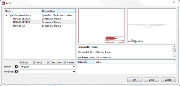
(on the left toolbar, or under the Edit menu) – is what you’ll use to place every single component on the schematic. The ADD tool opens up a library navigator, where you can expand specific libraries and look at the parts it holds. With a part selected on the left side, the view on the right half should update to show both the schematic symbol of the part and its package.

An example of navigating the ADD tool

The ADD tool also has search functionality– very helpful when you have to navigate through dozens of libraries to find a part. The search is very literal, so don’t misspell stuff! You can add wildcards to your search by placing an asterisk (*) before and/or after your search term. For example if you search for atmega328 you should find a single part/package combo in the SparkFun-DigitalIC library, but if you search *atmega328* (note asterisks before and after), you’ll discover two more versions of the IC (because they’re actually named “ATMEGA328P”). You’ll probably want to get accustomed to always adding an asterisk before and after your search term.

Searching the ADD tool. Wildcards!

To actually add a part from a library either select the part you want and click “OK”, or double-click your part.

Step 1: Add a Frame

The frame isn’t a critical component for what will be the final PCB layout, but it keeps your schematic looking clean and organized. The frame we want should be in the SparkFun-Aesthetics library, and it’s named FRAME-LETTER. Find that by either searching or navigating and add it to your schematic.

Adding the frame

After selecting the part you want to add, it’ll “glow” and start hovering around following your mouse cursor. To place the part, left-click (once!). Let’s place the frame so its bottom-left corner runs right over our origin (the small dotted cross, in a static spot on the schematic).

Frame added

After placing a part, the add tool will assume you want to add another – a new frame should start following your cursor. To get out of the add-mode either hit escape (ESC) twice or just select a different tool.

Step 2: Save (And Save Often)

Right now your schematic is an untitled temporary file living in your computer’s ether. To save either go to File > Save, or just click the blue floppy disk icon – . Name your schematic something descriptive. How about “BareBonesArduino.sch” (SCH is the file format for all EAGLE schematics).

As a bonus, after saving, your frame’s title should update accordingly (you may have to move around the screen, or go to View > Redraw).

Step 3: Adding the Power Input

Next we’ll add four different parts all devoted to our voltage supply input. Use the add tool for these parts:

Part DescriptionLibraryPart NameQuantity
5.5mm Barrel Jack (PTH)SparkFun-ConnectorsPOWER_JACKPTH1
0.1µF Ceramic CapacitorSparkFun-CapacitorsCAPPTH1
Voltage Supply SymbolSparkFun-AestheticsVCC1
Ground SymbolSparkFun-AestheticsGND2

All of these parts will go in the top-left of the schematic frame. Arranged like this:

Power circuitry placed

If you need to move parts around, use the MOVE tool – (left toolbar or under the Edit menu). Left-click once on a part to pick it up (your mouse should be hovering over the part’s red “+” origin). Then left click again when it’s where it needs to be.

Step 4: Microprocessor and Supporting Circuitry

Next we’ll add the main component of the design – the ATmega328 microprocessor – as well as some components to support it. Here are the parts we’ll add:

Part DescriptionLibraryExact Part NameQuantity
ATmega328P (PTH)SparkFun-DigitalICATMEGA328P_PDIP1
¼W ResistorsSparkFun-ResistorsRESISTORPTH-1/4W4
5mm LEDsSparkFun-LEDLED5MM3
0.1µF Ceramic CapacitorSparkFun-CapacitorsCAPPTH1
Voltage Supply SymbolSparkFun-AestheticsVCC2
Ground SymbolSparkFun-AestheticsGND4

To rotate parts as your placing them, either select one of the four options on the rotate toolbar – – or right click before placing the part. Place your microcontroller in the center of the frame, then add the other parts around it like so:

Microcontroller circuit added

Step 5: Adding the Connectors

Three connectors will finish off our design. One 8-pin connector to break out the analog pins, a 6-pin serial programming header, and a 2x3-pin ICSP programming header. Here are the three parts to add for this step:

Part DescriptionLibraryExact Part NameQuantity
8-Pin 0.1" HeaderSparkFun-ConnectorsM081X081
2x3 AVR Programming HeaderSparkFun-ConnectorsAVR_SPI_PRG_6PTH1
6-Pin Serial Programming HeaderSparkFun-ConnectorsARDUINO_SERIAL_PROGRAMPTH1
Voltage Supply SymbolSparkFun-AestheticsVCC2
Ground SymbolSparkFun-AestheticsGND2

Finally! Here’s what your schematic should look like with every part added:

Schematic with all parts added

Next we’ll wire net them all together.

Wiring Up the Schematic

With all of the parts added to our schematic, it’s time to wire them together. There’s one major caveat here before we start: even though we’re wiring parts on the schematic, we not going to use the WIRE tool – – to connect them together. Instead, we’ll use the NET tool – (left toolbar, or under the Draw menu). The WIRE tool would be better-named as a line-drawing tool, NET does a better job of connecting components.

Use NET not WIRE

Using the NET Tool

To use the NET tool, hover over the very end of a pin (as close as possible, zoom in if you have to), and left-click once to start a wire. Now a green line should be following your mouse cursor around. To terminate the net, left-click on either another pin or a net.

Routing GIF

The hard part, sometimes, is identifying which part on a circuit symbol is actually a pin. Usually they’re recognizable by a thin, horizontal, red line off to the side of a part. Sometimes (not always) they’re labeled with a pin number. Make sure you click on the very end of the pin when you start or finish a net route.

Route the Power Input Circuit

Start back in the upper left, and route the power input circuit like so:

Power circuit wired up

Whenever a net splits in two directions a junction node is created. This signifies that all three intersecting nets are connected. If two nets cross, but there’s not a junction, those nets are not connected.

Route the ATmega328 Circuit

Next we’ll route the ATmega328 to its supporting circuitry. There’s LEDs, a connector, resistor, capacitor and VCC/GND symbols to route to:

Wiring the ATmega circuit

Don’t forget to add nets between the LEDs, resistors, and GND symbols!

Making Named, Labeled Net Stubs

The remaining nets we have to make are not going to be as easy to cleanly route. For example, we need to connect the TXO pin on JP2 to the ATmega’s RXD pin, all the way on the other side. You could do it, it would work, but it’d be really ugly. Instead, we’ll make net “stubs” and give them unique names to connect them.

We’ll start by adding short, one-sided nets to each of the six pins on the serial connector. Begin by starting a net at a pin, just as you’ve been doing. Terminate the net by left-clicking a few grid-lengths over to the right of the pin. Then, instead of routing to another pin, just hit ESC to finish the route. When you’re done, it should look like this:

Net stubs added to connector pins

Next, we’ll use the NAME tool – (left toolbar, or under the Edit menu) – to name each of the six nets. With the NAME tool selected, clicking on a net should open a new dialog. Start by naming the net connected to the top, GND pin. Delete the auto-generated name (e.g. N$14), and replace it with “GND” (sans the quotation marks). This should result in a warning dialog, asking you if you want to connect this net to all of the other nets named “GND” (that would be every net connected to a GND symbol). Thanks for looking out for us EAGLE, but in this case Yes we do want to connect GND to GND.

After naming a net, you should use the LABEL tool – – to add a text label. With the LABEL tool selected, left-click on the net you just named. This should spawn a piece of text that says “GND”, left-click again to place the label down right on top of your net.

Follow that same order of operations for the remaining five net stubs. In the end, they should look like this (note the net connected to the TXO pin is named “RX”, and a “TX” net connects to RXI – that’s on purpose):

Net stubs named and labeled

VCC should be the only other net that warns you that you’ll be connecting to other nets named “VCC” (anything connected to a VCC voltage node). For the other named nets, we’ll need to create this same stub somewhere else. Where exactly? Well, we need to add a “RX” and “TX” net on the ATmega328, and a “DTR” nearby as well:

Naming and labeling RX, TX, and DTR

Even though there’s no green net connecting these pins, every net with the same, exact name is actually connected.

We need to do a lot of the same to connect the 2x3 programming header to the ATmega328. First, wire up the connector like so (naming/labeling MOSI, MISO, SCK, and RESET):

ICSP connecter wired

Then, back to the ATmega328, add the same four named/labeled nets:

ATmega328 SPI pins named/labeled

Phew – you’re done. Get excited, it’s about time to lay out a PCB! When your schematic is done, it should look a little something like this:

Final schematic


The schematic layout is done, but there are a few tips and tricks we’d like to share before moving over to the PCB layout portion of the tutorial.

Tips and Tricks

Names and Values

Every component on your schematic should have two editable text fields: a name and a value. The name is an identifier like R1, R2, LED3, etc. Every component on the schematic should have a unique name. You can use the NAME tool – on any component to change the name.

A part’s value allows you to define unique characteristics of that part. For example, you can set a resistor’s resistance, or a capacitor’s capacitance. The importance of a part’s value depends on what type of component it is. For parts like resistors, capacitors, inductors, etc. the value is a critical piece of information when you’re generating a bill of materials or assembly sheet. To adjust a part’s value parameter, use the VALUE tool – .

Verifying Connections

The SHOW tool – – is very useful for verifying that pins across your schematic are connected correctly. If you use SHOW on a net, every pin it’s connected to should light up. If you’re dubious of the fact that two like-named nets are connected, give the SHOW tool a try. SHOW-ing a net connected to GND, for example, should result in a lot of GND nets lighting up.

SHOWing a GND trace

As an alternative to show, you can temporarily MOVE a part a part to make sure nets are connected to it. Use MOVE to pick a part up, and the nets connected to it should bend and adjust to remain so. Just make sure you hit ESC to not move the part (or UNDO if you accidentally move it).

Moving a part to verify a connection

If all the nets connected to a part MOVE with it, all connections are good.

If a net isn’t moving along with the part, it’s not connected to the pin correctly. Double check to make sure you routed to the very end of the pin, and not a bit further:

Poorly routed net

If you have any nets incorrectly connected like above, DELETE – – it, and try re-netting.

Group Moving/Deleting/Etc.

Any tool that you use on a single component, can also be used on a group of them. Grouping and performing an action on that group is a two-step process. First, use the group tool – – to select the parts you want to modify. You can either hold down the left-mouse button and drag a box around them, or click multiple times to draw a polygon around a group. Once the group is made, every object in that group should glow.

After grouping, select the tool you want to use. The status box in the far bottom-left will have some helpful information pertaining to using the tool on a group:

Group move status box

In order to perform any action on a group, you have to select the tool, then hold down CTRL and right-click the group. After you CTRL+right-click, the tool will operate on the group just as it does a single component.

Copy/Paste

EAGLE’s Copy – – and Paste – – tools don’t work exactly like other copy/paste tools you may have encountered before. Copy actually performs both a copy and paste when it’s used. As soon as you copy a part (or any object on the schematic – name, text, net, etc.) an exact copy will instantly spawn and follow your mouse awaiting placement. This is useful if you need to add multiples of the same part (like GND nodes or resistors).

Paste can only be used to paste a group that has previously been copied to your clipboard. To use paste you first have to create a group, then (with the copy tool selected) CTRL+right-click to copy it, but hit ESC instead of gluing it down. This’ll store the copied group into your operating system’s clipboard, and you can use paste to place it somewhere. This tool is especially useful if you need to copy parts of one schematic file into another.

Going Further

This tutorial is the first of a pair. The next tutorial, Using EAGLE: Board Layout, will use the schematic we designed here to lay out a “Bare Bones Arduino” PCB. If you’re headed over to that tutorial next, you can get a head start by clicking the Generate/Switch to Board icon – – to create a board based on this schematic.


If you’d rather read about other EAGLE-related concepts, here are some tutorials you may want to check out:


learn.sparkfun.com |CC BY-SA 3.0 | SparkFun Electronics | Boulder, Colorado

How to Install and Setup EAGLE

$
0
0

How to Install and Setup EAGLE a learn.sparkfun.com tutorial

Introduction

Printed circuit boards (PCBs) are the backbone of every electronic gizmo out there. They’re not flashy like those microprocessors, or abundant like resistors, but they’re essential to making all components in a circuit connect together just right.

We LOVE designing PCBs here at SparkFun. It’s a love that we want to spread. It’s a skill that benefits electronics enthusiasts of every caliber. Through this and a series of tutorials, we’ll explain how to design a PCB using EAGLE – the same software we use to design all of our PCBs.

alt text

This first tutorial goes over how to install the software, and tailor-fit its interface and support files.

Why EAGLE?

EAGLE is one of many PCB CAD softwares out there. So you might ask: “What makes EAGLE so special?” We’re fond of EAGLE for a few reasons in particular:

  • Cross-platform– EAGLE can run on anything: Windows, Mac, even Linux. This is a feature not too many other PCB design softwares can boast.
  • Lightweight– EAGLE is about as svelte as PCB design software gets. It requires anywhere from 50-200MB of disk space (compared to the 10+GB more advanced tools might require). The installer is about 25MB. So you can go from download to install to making a PCB in minutes.
  • Free/Low-Cost– The freeware version of EAGLE provides enough utility to design almost any PCB in the SparkFun catalog. An upgrade to the next license tier (if you want to make a profit off your design) costs at least two orders of magnitude less than most high-end tools.
  • Community support– For those reasons, and others, EAGLE has become one of the go-to tools for PCB design in the hobbyist community. Whether you want to study the design of an Arduino board or import a popular sensor into your design, somebody has probably already made it in EAGLE and shared it.

Of course, EAGLE has its drawbacks too. More powerful PCB design tools out there might have a better autorouter, or nifty tools like simulators, programmers, and 3D viewers. For us though, EAGLE has everything we need to design simple-to-intermediate PCBs. It’s an excellent place to start if you’ve never designed a PCB before.

Recommended Reading

Here are a few tutorial and concepts you may want to familiarize yourself with before dropping down into this rabbit hole:

Download, Install, Run

EAGLE is available on Cadsoft’s (the developer company) download page. Grab the most recent version that matches your operating system (the software is available for Windows, Mac and Linux). It’s a relatively light download – about 45MB.

EAGLE installs just like any old program, it’ll self extract and then present you with a series of dialogs to configure the installation.

Licensing EAGLE

On the last screen of the installation process, you should be presented with a window like this:

EAGLE license setup screen

One of our favorite things about EAGLE is that it can be used for free! There are a few limitations to be aware of when using the free version:

  • Your PCB design is limited to a maximum size of 100 x 80mm (3.94 x 3.15in). 12.4 in2 of PCB real estate, which is still pretty darn big. Even if you’re designing a big ‘ol Arduino shield, you’ll still be well under the maximum size.
  • Only a two signal layers allowed. If you need more layers check into the Hobbyist or Standard licenses.
  • Can’t make multiple sheets in your schematic editor.
  • Limited to email or forum support.
  • For non-profit use only. If you’re going to go out and sell your design, maybe check into the “Light” version of the software.

Those limitations still make EAGLE an amazing piece of software. Engineers here at SparkFun could design 99% of our boards using the freeware version, if not for that pesky non-profit stipulation. You still have access to all phases of the EAGLE software, including the Autorouter.

If you need to upgrade your license there are a few versions available. Most licenses are still incredibly low priced (in comparing to the other stuff out there).

Exploring the Control Panel

The first time you open up EAGLE, you should be presented with the Control Panel view. The Control Panel is the “homebase” for Eagle, it links together all of the other modules in the software.

Control Panel Overview

You can explore the six separate trees in the control panel, which highlight separate functions of the software:

  • Libraries– Libraries store parts, which are a combination of schematic symbol and PCB footprint. Libraries usually contain a group of related parts, e.g. the atmel.lbr stores a good amount of Atmel AVR devices, while the 74xx-us.lbr library has just about every TTL 74xx series IC there is.
  • Design Rules– Design rules are a set of rules your board design must meet before you can send it off to the fab house. In this tree you’ll find DRU files, which are a a pre-defined set of rules.
  • User Language Programs (ULPs)– ULPs are scripts written in EAGLE’s User Language. They can be used to automate processes like generating bill of materials (bom.ulp), or importing a graphic (import-bmp.ulp).
  • Scripts– Script files can be used to customize the EAGLE user interface. In one click you can set the color scheme and assign key bindings.
  • CAM Jobs– CAM jobs can be opened up by the CAM processor to aid in the creation of gerber files.
  • Projects– This is where each of your projects are organized into a single project folder. Projects will include schematic, board design, and possibly gerber files.

Exploring the Control Panel View

If you select a file in a tree, information about it will appear in the right-hand portion of the window. This is a great way to explore libraries, project designs (EAGLE comes with some fun examples), or to get a good overview of what a script’s purpose is.

Using the SparkFun Libraries

Included with EAGLE is an impressively list of part libraries, which you can explore in the Control Panel view. There are hundreds of libraries in here, some devoted to specific parts like resistors, or NPN transistors, others are devoted to specific manufacturers. This is an amazing resource! But it can also be a bit overwhelming. Even if you just want to add a simple through-hole electrolytic capacitor, there are dozens of libraries and parts to sort through to find the right thing.

Instead of using the hundreds of default libraries, you can use the SparkFun EAGLE Libraries, which are filtered down to only include the parts that we’ve used in designs ourselves. And they’re constantly updated with new parts we’ve discovered.

Here’s how you can install and use the SparkFun libraries instead of (or in addition to) the default ones:

Step 1: Download the SparkFun Libraries

The most recent version of the libraries can always be found in the GitHub repository. For help using GitHub, check out our Using GitHub tutorial. Basically, all you’ll need to do from the main repository page is click “Download ZIP”.

Downloading from github

Save the ZIP file somewhere handy. Then extract the folder – don’t forget where it is!

Step 2: Updating the Directories Window

Back to the EAGLE Control Panel window now. Go to the “Options” menu and then select “Directories”. This is a list of computer directories where EAGLE looks when it populates all six objects in the tree view…including libraries.

Opening the directories dialog

In the “Libraries” box is where we’ll add a link to the directory where the SparkFun EAGLE libraries are stored. There are a few options here. If you’d like to keep the default libraries and add the SparkFun library, add a semicolon (;) after “$EAGLEDIR\lbr”, and paste the SparkFun EAGLE Libraries directory location after that.

Adding the SparkFun EAGLE libraries directory

Step 3: “Using” Libraries

Now, when you go back and look at the “Libraries” tree, there should be two folders included, one of which should be our SparkFun Eagle Libraries. The last step is to tell EAGLE that, for now at least, we don’t want to use the default libraries. To do this, right click on the “lbr” folder, and select “Use none”.

Un-using the default libraries

Then, right-click on the “SparkFun-Eagle-Libraries-master” folder, and select “Use all”. Then check the libraries in each of the two folders. Next to them should be either a grey or green dot. A green dot next to a library means it’s in use, a grey dot means it’s not. Your libraries tree should look a little something like this:

Correctly set libraries tree. Default lbr's not active, SparkFun lbrs ready to go!

If you’ve created library parts that you would like to share with SparkFun to include in our Eagle library, visit this tutorial to see how.

Opening a Project and Explore

EAGLE is packaged with a handful of nifty example PCB designs. Open one up by expanding the “Projects” tree. From there, under the “examples” folder open up the “arduino” project by double-clicking the red folder (or right-clicking and selecting “Open project”). Note that, in this view, project folders are red and regular folders are the standard yellow.

Opening a project

Opening the project should cause two more EAGLE windows to spawn: the board and schematic editors. These are the yin and the yang of EAGLE. They should be used together to create the finished product that is a functional PCB design.

Board and schematic view both open

Schematic (left) and board editors both open. Click to embiggen.

The schematic editor (on the left above) is a collection of red circuit symbols which are interconnected with green nets (or wires). A project’s schematic is like the comments in a program’s code. It helps tell the story of what the board design actually does, but it doesn’t have much influence on the end product. Parts in a schematic aren’t precisely measured, they’re laid out and connected in a way that’s easy to read, to help you and others understand what’s going on with the board design.

The board editor is where the real magic happens. Here colorful layers overlap and intersect to create a precisely measured PCB design. Two copper layers – red on top, blue on the bottom – are strategically routed to make sure different signals don’t intersect and short out. Yellow circles (on this design, but they’re more often green) called “vias” pass a signal from one side to the other. Bigger vias allow for through-hole parts to be inserted and soldered to the board. Other, currently hidden, layers expose copper so components can be soldered to it.

Keep Both Windows Open!

Both of these windows work hand-in-hand. Any changes made to the schematic are automatically reflected in the board editor. Whenever you’re modifying a design it’s important to keep both windows open at all times.

If, for instance, you closed the board window of a design, but continued to modify a schematic. The changes you made to the schematic wouldn’t be reflected in the board design. This is bad. The schematic and board design should always be consistent. It’s really painful to backtrack any changes in an effort to reattain consistency. Always keep both windows open!

There are a few ways to tell if you don’t have consistency between windows. First, there’s a “dot” in the lower-right hand corner of both windows. If the dot is green, everything is groovy. If the dot is magenta, a window’s probably closed that shouldn’t be. Second, and more obvious, if you close either of the two windows a big, huge warning should pop up in the other:

Annotation severed warning. Eeep!

If you see that warning STOP doing anything, and get the other window back open. The easy way to get either a board or schematic window back open is by clicking the “Switch to board/schematic” icon – / (also found under the “File” menu).

Navigating the View

This is a subject that’s usually glazed over, but it’s important to know how to navigate around both of these windows.

To move around within an editor window, a mouse with a scroll wheel comes in very handy. You can zoom in and out by rotating the wheel forward and backward. Pressing the wheel down, and moving the mouse allows you to drag the screen around.

If you’re stuck without a three-button mouse, you’ll have to resort to the view options to move around the editor views. All of these tools are located near the middle of the top toolbar, or under the “View” menu. The zoom in – – and zoom out – – tools are obviously handy. So is the “Zoom select” tool – – which alters the view to your selection. But really, if you’re serious about using EAGLE…get a mouse!

Configuring the UI

EAGLE’s user interface is highly customizable. Anything from the background color, to layer colors, to key bindings can be modified to fit your preference. Better tailoring your interface can make designing a PCB much easier. On this page we’ll talk about how we at SparkFun prefer to customize our UI. None of these steps are required. Customize your UI as you see fit. These are just the settings that we’ve grown accustomed to.

Setting the Background Color

The first adjustment we always make to the UI is the background color of the board editor. The standard white background doesn’t always meld very well with the array of colored layers required for board design. Instead, we usually opt for a black background.

To change the background color, go up to the “Options” menu and select “User interface”.

Inside the “Layout” box you can set the background to black, white, or a specific color.

Adjusting the user interface

There are other options in this box to be explored, but you may want to hold off on adjusting most until you have more experience with the software.

Adjusting the Grid

Another UI improvement we like to make in the board editor is turning the grid on. Dimensions and sizes are so important to the design of your PCB, having some visible reminders of size can be very helpful. To turn the grid view on, click the icon near the top-left corner of the board window (or go to the “View” menu and select “Grid”).

Adjusting the grid

Switch the “Display” radio button over to “On”. We’ll also make the grid a bit less fine by setting the “Size” to 100 mil (0.1") and “Alt” to 50 mil (0.05").

Running Scripts

Scripts are a much more streamlined way to quickly configure your interface. With one click of the button, you can automatically set up all of your colors and key binds. Script files can also be shared, and run by anyone. Running the SparkFun EAGLE script will get your UI to exactly match ours.

First, click here to download the script (in a zip folder). Unzip the “spk.scr” file to a location you’ll remember.

Then you’ll need to run the script. In the board window click on the Script icon – (or go to “File” then “Execute Script”). In the file browser, select the “spk.scr” file you just downloaded and unzipped.

This should automatically set up your color scheme to look a little something like this:

Board view after running script

This UI setup is presents a nice logical view of the layers. The important copper layers are very visible, but distinct (red on top, blue on bottom, green for vias), and the silkscreen is white as it is on most PCB designs.

All of these colored layers will make more sense as you continue to use and explore EAGLE.

Going Further

If you’ve got EAGLE set up, and you’re chomping at the bit to start designing a PCB, your next step should be over to our our 2-part Using EAGLE tutorials: Using EAGLE: Schematic and Using EAGLE: Board Layout. That pair of tutorials will explain how to go from a schematic design, to laying out and routing a PCB, to generating gerber files and sending them to a fab house.

Schematic and board from Using EAGLE tutorials

Or here are some other tutorials in our EAGLE series:


learn.sparkfun.com |CC BY-SA 3.0 | SparkFun Electronics | Boulder, Colorado

Using the Arduino Pro Mini 3.3V

$
0
0

Using the Arduino Pro Mini 3.3V a learn.sparkfun.com tutorial

Introduction

The original, true-blue Arduino is open-source hardware, which means anyone is free to download the design files and spin their own version of the popular development board. SparkFun has jumped on this opportunity and created all sorts of Arduino variants, each with their own unique features, dimensions, and applications. Now one of those variants has landed in your hands; congratulations! It’s a wild world out there in microcontroller-land, and you’re about to take your first step away from the wonderful – though sometimes stifling – simplicity of the Arudino Pro Mini.

iso shot of the Arduino Pro mini 3.3V

In this tutorial, we’ll go over how to set up and use the 3.3V Arduino Pro Mini, everything from assembling the tiny Arduino to programming it.

To follow along, you’ll need a few extra items:

The FTDI Basic will be used to program (and power) the Pro Mini. The headers are optional, but they’re our preferred way to interface other devices to the Pro Mini.

Assembly of the Pro Mini also requires soldering. This is a great place to start soldering, if you’ve never done it before! The joints are all easy, through-hole jobs. So grab a soldering iron and some solder and check out our how to solder tutorial.

Suggested Reading

This project tutorial builds on a few more conceptual tutorials. If you’re not familiar with the subjects below, consider reading through their respective tutorials first:

What It Is (and Isn't)

So what differentiates the Arduino Pro Mini from the Arduino Uno? Well, the most obvious difference is the form factor. The Pro Mini’s pretty…mini, measuring in at just 1.3x0.70". It’s about ⅙th the size of the Arduino Uno. The compact size is great for projects where you may need to fit the Arduino into a tiny enclosure, but it also means that the Pro Mini is not physically compatible with Arduino shields (you could still hard-wire the Mini up to any Arduino shield).

Pro Mini size comparison

Comparing the size of a standard Arduino Uno with the (aptly named) Pro Mini.

The Mini packs almost as much microprocessor-punch as the regular Arduino, but there are a few major hardware changes you should be aware of before you start adapting your project to the Mini. The first glaring hardware difference is the voltage that the Mini operates at: 3.3V. Unlike the Arduino Uno, which has both a 5V and 3.3V regulator on board, the Mini only has one regulator. This means that if you’ve got peripherals that only work at 5V, you might have to do some level shifting before you hook it up to the Pro Mini (or you could go for the 5V variant of the Pro Mini).

Another major variation from the standard Arduino lies in the speed at which the ATmega328 runs. The Pro Mini 3.3V runs at 8MHz, half the speed of an Arduino Uno. We put a slower resonator on the Mini to guarantee safe operation of the ATmega. That said, don’t let the slower speed scare you away from using the Mini; 8MHz is still plenty fast, and the Mini will still be capable of controlling almost any project the Arduino Uno can.

Speed grades of ATmega328

One last missing piece of hardware is the Atmega16U2-based USB-to-Serial converter, and the USB connector that goes with it. All of the USB circuitry had to be eliminated for us to make the Pro Mini as small as possible. The absence of this circuit means an external component, the FTDI Basic Breakout, is required to upload code to the Arduino Pro Mini.

The FTDI Basic Breakout

Schematic and Pin-out

The schematic of the Pro Mini can be broken down into three blocks: the voltage regulator, the ATmega328 and supporting circuitry, and the headers.

alt text

The Pro Mini’s pins surround three of the four sides. The pins on the short side are used for programming, they match up to the FTDI Basic Breakout. The pins on the other two sides are an assortment of power and GPIO pins (just like the standard Arduino).

Annotated Pro Mini pins

There are three different power-related pins: GND, VCC, and RAW. GND, obviously, is the common/ground/0V reference. RAW is the input voltage that runs into the regulator. The voltage at this input can be anywhere from 3.4 to 12V. The voltage at VCC is the voltage supplied to the Pro Mini. If a voltage is applied to RAW, the voltage here should be a regulated 3.3V.

Four pins are actually not located on the edge of the board: A4, A5, A6 and A7. Each of these analog pins is labeled on the back side of the board.

Back of board

A4 and A5’s location may be very important if you plan on using I2C with the Pro Mini – those are the hardware SDA and SCL pins.

Assembly

The Arduino Pro Mini doesn’t look like much when you first get it; it’s as bare-bones as can be. We’ve left it up to you to solder headers or wires into the open through-holes. There are a few things to make you aware of though.

First, decide how you want to connect the FTDI Basic Breakout to the Pro Mini’s programming header. The programming header is a row of six pins on the side of the board, labeled “BLK”, “GND”, “VCC”, “RXI”, “TXO”, and “GRN”. Since the FTDI Basic board is equipped with a female header, it’s usually best to equip your Mini’s programming header with mating male headers, either straight or right-angle.

Breadboarded Pro Mini

This Pro Mini had male headers soldered into all pins, so it could slot directly into a breadboard. Notice the programming header pins are soldered “upside-down”, to keep them accessible.

The remaining assembly choices are up to you. There are many options; you could solder in male headers to make it breadboard-compatible, female headers to make it compatible with jumper wires, or just solder stranded-wire straight into the pins.

Uncertain 7-Cube assembly

The Arduino Pro Mini in the Uncertain 7-Cube Project used a combination of right and straight male headers.

Versatility is what makes this board so great, and you can assemble it in whatever way makes the most sense for your project.

Powering

The most important factor in any project is what’s going to power it. The Pro Mini doesn’t have a barrel jack, or any other obvious way to connect a power supply, so how do you power the thing?

Pick a power source that suits your project. If you want something that matches the compactness of the Pro Mini, a battery – LiPo, alkaline, coin cell, etc. – may be a good choice. Or you could use a wall power supply along with a barrel jack adapter.

If you have a supply that’s greater than 3.3V (but less than 12V), you’ll want to connect that to the RAW pin on the Mini. This pin is akin to the VIN pin, or even the barrel jack, on the Arduino Uno. The voltage applied here is regulated to 3.3V before it gets to the processor.

If you already have a regulated 3.3V source from somewhere else in your project, you can connect that directly to the VCC pin. This will bypass the regulator and directly power the ATmega328. Don’t forget to connect the grounds (GND) too!

There is a third power option that’s only usually available while you’re programming the Pro Mini. The FTDI Basic Breakout can be used to power the Mini via your computer’s USB port. Keep in mind that this option may not be available when your project has entered the wild, absent from any computers or USB supplies.

FTDI powering and programming the Pro Mini

That leads us to the next section…programming the Arduino Pro Mini.

Programming

If you’ve never used an Arduino before (how bold of you to go straight for the Mini!), you’ll need to download the IDE. Check out our tutorial on installing Arduino for help on that subject.

The first time you plug the FTDI Basic Breakout in, you may need to install drivers for it. Check out our Installing FTDI Drivers tutorial for help there.

Once both Arduino and the FTDI drivers are installed, it’s time to get programming. We’ll start by uploading everyone’s favorite sketch: Blink. Open up Arduino, then open the Blink sketch by going to File > Examples > 01.Basics > Blink.

Opening Blink

Before we can upload the sketch to the Mini, you’ll need to tell Arduino what board you’re using. Go to Tools > Board and select Arduino Pro or Pro Mini (3.3V, 8 MHz) w/ ATmega328. This tells Arduino to compile the code with an 8MHz clock speed in mind, that way the delay(1000); calls will actually delay one second.

Arduino board selection

You’ll next need to tell Arduino which serial port your FTDI Basic Breakout has been assigned to. On Windows this will be something like COM2, COM3, etc. On Mac it’ll look something like /dev/tty.usbserial-A6006hSc.

Finally, you’re all set to upload the sketch to your Mini. Click on the Upload button (the right-pointing arrow). After a few moments you should see the red and green RX/TX LEDs on your FTDI board flash, followed by a “Done Uploading” message in Arduino’s status bar. Voilà, Blinky! The Mini may be missing a few components, but it’s got the most important component: LEDs!

Going Further and Resources

Now that you know the basics of hooking up the Arduino Pro Mini, what project are you going to stick it into? Need some inspiration? Check out some of these tutorials:

Resources

Like its predecessor, the Arduino Pro Mini is open-source hardware, which means all of the design files are free to view and modify:

For more information on the Arduino Pro Mini, first check out our product page as well as Arduino’s Pro Mini homepage.


learn.sparkfun.com |CC BY-SA 3.0 | SparkFun Electronics | Boulder, Colorado

Electric Imp Breakout Hookup Guide

$
0
0

Electric Imp Breakout Hookup Guide a learn.sparkfun.com tutorial

impRoduction

The electric imp is a deviously awesome development platform. Disguised as an every day SD card, the imp is actually a unique combination of microprocessor and WiFi module. The imp makes connecting any device to the Internet a breeze. Looking to catch on with this “Internet of Things” fad? The imp is an excellent place to start.

The electric imp card

The electric imp card. (Note: We didn’t misplace the copywriter, electric imp is their brand convention.)

In this tutorial, we’ll be explaining how to use the imp with one of our Breakout Boards. This simple PCB assembly houses the bare minimum you might need to get an imp up-and-running. First, we’ll cover how to hook up the hardware end of the imp/Breakout combo. Following that we’ll head over into the firmware domain, programming the imp to blink LEDs and read analog and digital inputs. The last code example shows off the coolest part of the imp: controlling hardware over the Internet!

The electric imp Breakout

The electric imp Breakout Board.

Requirements

Of course, you’ll need an imp and a Breakout Board. Aside from those two parts, we’ll use a few common electronics parts you may already have. Here’s a wishlist of everything we’ll be using. If you’d like to use some parts you may already have around the house


In addition to those items, you’ll also need the following non-SparkFun materials:

  • Wireless network with Internet access
  • electric imp planner account (sign up is free/easy)
  • electric imp planner website pulled up in your web browser
  • SmartPhone w/ the electric imp app (Android or iOS)

Tools

There will be some soldering involved. The Breakout Board does not come with header pins soldered on, which you’ll need in order to interface with the imp’s I/O pins. You’ll need a simple soldering iron and a bit of solder. (If you’ve never soldered before, this is a great place to start! The solder points are easy, through-hole jobs.)

Before We Begin

This tutorial builds upon some basic electronics concepts. If you aren’t familiar with any of the topics below, consider reading through that tutorial first:


Let’s start by overviewing the imp card itself. It’s hard, at first, to wrap your head around the fact that this little, white SD-looking card is actually a powerful WiFi-enabled microcontroller platform.

About the imp

It may look like an everyday SD card, but the electric imp is much, much more. It's a WiFi-enabled microprocessor. It’s programmable over the air. It’s got GPIOs, UARTS, I2Cand SPI interfaces, pulse-width-modulation, digital-to-analog and analog-to-digital converters. Basically, it’s what you’d get if you smushed an ARM microprocessor and a WiFi module down into a tiny SD-card-sized package.

imp card boxed up

The imp provides an easy, integrated way to connect almost any hardware device to Internet services. It is well suited to be the backbone of your Internet-enabled project, whether you’re remotely controlling your electric blanket or triggering an irrigation system via a web browser. Connecting your imp to a wireless network and programming it is a simple, streamlined process.

The Hardware: 6 Wondrous I/Os

The imp is basically made of pure awesome. But, if we lift the hood of awesomeness for a moment, we can talk a bit about the imp's hardware. The platform of the electric imp is a Cortex-M3 microprocessor. Just like any microprocessor, the imp has a collection of input and output pins, each with unique functions. There are six addressable I/O pins – not as many as an Arduino, but it makes up for it in terms of functionality. The imp has three UARTs, two I2C and SPI interfaces, and two DAC outputs; plus each pin can act as an ADC input and PWM output.

Table from Imp's Wiki Page
Pin #UART1289UART57UART12I2C89I2C12SPI257SPI189DACADCPWM
1CTSTXSCLSCLKYesYesYes
2RTSRXSDAMISOYesYes
5TXSCLKYesYesYes
7RXMOSIYesYes
8TXSCLMOSIYesYes
9RXSDAMISOYesYes

Of course, each of those pins can also be used as a simple inputs (with or without pull-up resistors) or outputs, sinking/sourcing up to 4mA each.

Also in that tiny SD package is a WiFi module, an antenna, and a light sensor. We’ll find out why the light sensor is critical in the coming pages.

The imp is a 1.8-3.3V device, supplying it any more voltage than that can be harmful. It can require up to 400mA (worst-case), but it’ll usually pull about 80mA (even 5mA in a power-save mode).

The IDE: The imp Planner

All code written for the imp is done online, in a web browser. The integrated development environment (IDE) for the imps is called the planner. Everyone can (freely) create their own account on the planner, where both your programs and your imps are kept safe and secure.

The planner window

There are certainly pros and cons to this “always online” approach (though you can write and save every program locally, and upload it when you’re ready). Still, it seems like a good solution for this type of platform.

The Language: Squirrel

Firmware for the imp is written in a language called Squirrel. Squirrel is an object oriented language similar to Javascript, but unlike most embedded system programming languages we’ve encountered (namely Arduino). Entering imp development from the world of Arduino may be somewhat jarring. There are no loop() or setup() functions, instead most actions are event or timer-driven.

Example of squirrel language

There are tons of great examples on electric imp’s wiki page, and if you're truly interested in learning Squirrel, check out the Squirrel homepage. There’s also the Electric Imp API to familiarize yourself with. These are functions and libraries used to perform actions with the imp’s GPIO pins and other hardware functionality.

About the Breakout

In order to use an electric imp, two pieces of hardware are required: the imp card and the impee. An impee is the piece of hardware that houses the imp. Aside from having a standard SD socket for the imp to slide into, the impee also needs to provide power to the imp, and do something with the imp’s I/O pins. Our impee for this tutorial is as simple as it gets…a breakout board.

Top/bottom view of imp breakout

Top and bottom views of the imp breakout.

The imp breakout provides the bare minimum you should need to add an electric imp to your project. There’s an SD socket, a step-down voltage regulator, and every I/O pin of the imp is broken out to a 0.1"-spaced header.

Powering the Breakout

A big chunk of the circuitry on the Breakout board is a 3.3V TPS62172 step-down regulator (and the inductor/capacitors supporting it). This regulator allows for input voltages anywhere between 3.3V and 17V (voltages in the upper end of that range may produce some heat). It can support up to 500mA of continuous current.

There are three power inputs on the board, all of which, are fed into the on-board 3.3V regulator:

  • “VIN” header - This standard 0.1" header feeds directly into the 3.3V regulator.
  • Battery input - These are the pins and pads labeled “+” and “-”. The footprint of the two through-hole pins matches up to a PTH 2-pin JST connector, which mates with our LiPo batteries (or AA batteries). This input needs to be selected using the jumper (see below).
  • USB mini-B connector - This power input should feed a clean, 5V source into the breakout board’s regulator. The USB voltage supply can come from either a mini-B cable connected to your computer or a USB wall adapter. This input needs to be selected using the jumper (see below).

Where the power inputs are

Setting the Jumper

To use either the battery or USB power inputs, a jumper must be set on the board. To use the jumper, first solder a 3-pin male header to the jumper pins. Then use a 2-pin jumper to span from the middle pin, to whichever of the two inputs you’d like to use.

Jumper set to USB

In this image, the jumper is set to apply USB power to the imp breakout. A JST connector was soldered to the battery input pins, in case we want to use a LiPo to power the board.

The Breakout’s Schematic

There are three main components to the breakout board: a TPS62172 step-down regulator (U2), the electric imp socket (U1), and the ATSHA204 authentication chip (U3).

Electric Imp Breakout Schematic

electric imp Breakout Schematic. Click the image to get a larger picture, or click here to view the schematic as a PDF.

Pinout

All of the imp’s GPIO pins are broken out to the 0.1"-spaced header, along with a few related power pins:

  • GND - Common pin for input voltage.
  • VIN - Input voltage supply fed into regulator.
  • PIN1 - imp pin 1 (DAC, UART1289 CTS, UART12 TX, I2C12 SCL, SPI189 SCLK)
  • PIN2 - imp pin 2 (UART1289 RTS, UART12 RX, I2C12 SDA, SPI257 MISO)
  • PIN5 - imp pin 5 (DAC, UART57 TX, SPI257 SCLK)
  • PIN7 - imp pin 7 (UART57 RX, SPI257 MOSI)
  • PIN8 - imp pin 8 (UART1289 TX, I2C89 SCL, SPI189 MOSI)
  • PIN9 - imp pin 9 (UART1289 RX, I2C89 SDA, SPI189 MISO)
  • CD - Card detect. This signal will connect to GND whenever a card is inserted into the socket.
  • 3V3 - 3.3V output from regulator.
  • GND - Common ground.

ID Chip

There’s actually one more piece of hardware required of the impee: an ID chip, which provides each impee with a unique identification code. This means that every impee you encounter should include an Atmel ATSHA204 authentication chip. The imp automatically interfaces with this chip every time it boots up, so it can identify which impee it’s plugged into. This actually turns out to be pretty awesome, because the program that an imp runs depends on what impee it’s plugged into. If you had two impees in your house – say controlling an irrigation system and another controlling a coffee machine – one, single imp would run two different programs depending on which machine it was plugged into.

You shouldn’t ever have to fuss with the ID chip. In fact, you can forget we ever said anything about the ATSHA204!

Hardware Hookup

The hardware hookup approach in this guide is just one of many ways to use the board. The breakout is made to be a versatile extension of the imp. You can connect whatever you want to the imp pins, and power the board however your project requires.

Solder Headers

In order to do much with the input/output capability of the imp, you’ll need to solder to the broken out pins. If you want to use the imp Breakout with a breadboard or perfboard, 0.1" male headers make for a good choice. Depending on your application, you could swap the headers with wire, female headers, screw terminals, or a variety of other connectors.

We’re going to solder male headers into the board, so we can use it with a breadboard later on.

Headers soldered on to breakout, inserting int breadboard

Apply Power

Depending on what you want to use for your power source there are a few options here. You could use the on-board USB connector. Or you could solder down a 2-pin JST connector, and plug battery (LiPo or AA) into the board to make it mobile. If you go with either of those options, you’ll also need to set the jumper.

Jumper set to USB power

Note how the jumper is set. We’re using USB to power the imp in this picture.

Alternatively, you can apply power straight to the headers labeled “VIN” and “GND”. This pin bypasses the jumper and goes straight to the regulator.

Plug in the imp!

Nothing too complicated about this part. Plug the imp card in so the suspicious little imp logo is facing up.

If you’ve got power to the board, once plugged in, the imp should start blinking orange. If there’s no blinking on the card, it’s probably not getting any power. Double-check that the jumper is set correctly.


What’s all that blinking signify? How do we get the imp connected to our wireless network? Read on!

BlinkUp

Blink Codes

The imp has an internal red/green LED, which is used to tell the world what state it’s currently in. If you’ve just plugged the imp in, and haven’t told it how to get on your WiFi network, it should be blinking orange (red/green simultaneously). Here are the rest of the codes to look out for:

imp blink codes (from the imp dev wiki)
ColorSpeedimp State
Orange1 HzNo WiFi settings
GreenSingle PulseSuccessfully received configuration via Blinkup.
RedTriple-pulseFailed to receive configuration via Blinkup.
Red1 HzAttempting to connect to WiFi.
Red, Orange, Off1 HzGetting IP address (via DHCP).
Orange, Red, Off1 HzGot IP address, connecting to server.
Green0.5 HzConnected to cloud (turns off after 60 seconds).
Red2 HzConnection lost, attempting to reconnect.
NoneNormal operation

Let’s make that LED blink green! Time to send a BlinkUp.

BlinkUp

To get your imp connected to your WiFi network as well as the online imp servers, you need to go through the process electric imp calls commissioning. There’s a great write-up on the commissioning process over on electric imp’s wiki page. Here’s the gist of it, as well as a few tips.

Before you begin, you’ll need to make an Electric Imp account, by visiting the planner page.

Updating the imp with your WiFi credentials is a unique process. The imp card has a built-in light-sensor, looking out of the little window on the short, flat edge of the imp. The light-sensor can be used to process small amounts of precisely modulated data in the form of a blinking light.

The edge of the imp card where the light sensor window is

To generate this blinking light, you need the electric imp app installed on your smartphone (iOS or android). Go download that app if you haven’t already!

Follow the directions in the app, and prepare to update the imp with your WiFi network. Then, when your settings all look correct hit the Send BlinkUp button. Then quickly place the screen of the phone as close to the imp’s light sensor as possible.

BlinkUp in action

Avert your eyes! Unless you enjoy staring into bright, white strobing lights.

If all goes well, there should be a very short green blip of the LED, followed by a few blinks of red and orange. When the imp starts blinking green once a second, you know you’ve got your imp commissioned yay!

Troubleshooting

If you’re imp isn’t yet in the blinky green phase, use the LED blink codes to find out where it’s failing. Here are some recommended steps, depending on the failure point:

  • Connecting to the server (orange, red, off) - Make sure there’s no firewall blocking the imp’s way to the Internet (and make sure your WiFi network has an Internet connection in the first place).
  • Getting IP address via DHCP (red, orange, off) - Double check your WiFi password.
  • Attempting WiFI connection (red) - Double check your WiFi network name (SSID).

If all of the above are set correctly, try sending the BlinkUp one more time. We’ve found that it helps to close out all other app, or even try resetting your phone if it continues to fail.

You can also try turning off the room lights for a moment. Pinching the imp, just above and below the light-sensor window can help as well.

Example 1: I/O Control

The electric imp can do most anything an Arduino or similar microcontroller can. It’s got analog-to-digital converters, PWM, SPI, I2C, UARTs, and it even has digital-to-analog converters. In this first snippet of example code, we’ll show off the basics of I/O control – digital and anlog input/output.

Example 1 circuit image

Using the Planner

After sending the BlinkUp and commissioning your imp, it should show up in your planner as a lone, blue rectangle. The word “Blank” will appear in the box. The box’s name will reflect the code that the imp is running.

Planner with blank imp

To upload code to the imp, you need to click the “slider” icon in the top-right of the blue box, and select the code you wish to stick on there. I guess that means we need some code then?!

Uploading code in planner

Example Code

The setup for this example code requires three unique components: an LED, potentiometer, and a button (plus a current-limiting resistor for the LED). Here’s a fritzing diagram and schematic (click to see it bigger) for our circuit:

Example 1 Fritzing diagram and schematic

Make sure the imp is getting power. USB is usually the quickest/easiest way to apply power to the breakout board, but you’ll need to set the jumper accordingly.

The Code

To create a new piece of code, click over to the “Code” tab of the planner. Then click the “+” in the top left and give your new piece of code a name (we’ll go with “LED-Trigger-Wiper”).

Making a new piece of code and naming it

This’ll open up a blank piece of code. Copy and paste everything from the below box, into your code window and save.

language:Squirrel
/* Digital Input, Analog Input, PWM Output Example
   by: Jim Lindblom
   SparkFun Electronics
   date: July 15, 2013
   license: Beerware. Use, reuse, and modify this code however you see fit.
   If you find it useful, buy me a beer some day!

   This is a simple piece of code which uses an LED, potentiometer, and button.
   The LED connects to pin 1 through a 47 ohm resistor. The cathode of the LED should connect to ground.
        This means writing pin 1 will turn the LED on, and writing it to 0 turns the LED off.
   The button connects on one side to pin 9, and the other pin of the button goes to ground.
        We'll use the internal pull-up resistors on pin 9 to bias the button high.
        When the button is pressed, pin 9 should read as low.
   The wiper of the potentiometer is connected to pin 5. The other two pins of the pot should be
        connected to +3.3V and GND. This'll make the voltage at pin 5 adjustable from 0-3.3V.
*/

////////////////////////////////////////
// Function definitions               //
////////////////////////////////////////

local ledState = 1; // Says local, but think of this as a global var. Start with LED on

// function pin9Changed() will be called whenever pin 9 goes from high->low or low->high
function pin9changed()
{
    local buttonState = hardware.pin9.read(); // Read from the button pin

    if (buttonState == 0) // Button will read low if pressed
    {
        ledState = ledState ? 0 : 1;    // Flip flop ledState
        server.log("Button pressed!");
    }
    else // Otherwise button was released, no action
    {
        server.log("Button released");
    }
}

// Loop constantly updates the LED. If ledState is 1, we'll read the pot, and set the LED brightness accordingly.
// If ledState is 0, we'll just turn the LED off. ledState is updated in the pin9Changed() function.
function loop()
{
    if (ledState == 1)
    {
        local rawValue = hardware.pin5.read();  // Read from the potentiometer. Returns a value between 0 and 65535.
        rawValue /= 65535.0;  // Make rawValue a % (and a float). The pin write function requires a value between 0 and 1.
        hardware.pin1.write(rawValue);  // Pin 1 is already configured as PWM, write potentiometer value
    }
    else
    {
        hardware.pin1.write(0);  // Write pin 1 low -- LED off
    }

    // This must be called at the end. This'll call loop() again in 10ms, that way it'll actually loop!
    imp.wakeup(0.01, loop);
}

////////////////////////////////////////
// Setup Stuff: Runs first at startup //
////////////////////////////////////////
hardware.pin1.configure(PWM_OUT, 0.0005, 0.0);   // Configure Pin 1 as PWM output, 5ms period, 0% high (off)
hardware.pin5.configure(ANALOG_IN); // Configure pin 5 as analog input
hardware.pin9.configure(DIGITAL_IN_PULLUP, pin9changed); // Configure pin 9 as digital input (with pull-up enabled). On change it'll call function pin9changed().
imp.configure("LED Trigger Wiper", [], []);

loop(); // Call loop, and let the program go!

This’ll save a copy to your account on electric imp’s server. You’ll now always be able to open it up, view it, and modify it by clicking on the link in the “code” tab.

The code creates a simple adjustable-brightness LED controller. The brightness of the LED is adjusted by turning the potentiometer. Pressing the button will turn the LED on and off.

Explaining the Code

If you’re only used to working with Arduino sketches, this code may make very little sense, electric imp programs have a very different “flow” to them. Begin by looking at the 5 lines of code at the bottom of the program (under the “Setup Stuff” header). This is actually where our imp starts when it begins to run it’s code. Everything above is simply a function definition.

Most of this code makes heavy use of the imp’s pin class, which handles a lot of the I/O control. If you’re used to using Arduino GPIO’s, the imp’s API isn’t too different. You have to set the pin up as either an input or output, analog or digital. Then write or read to the pin accordingly.

At the end of the setup, we make a call to the loop() function, which is defined above. loop() is simple, it checks a global variable named ledState. If ledState is 1, we read the potentiometer voltage, and adjust the brightness of our LED accordingly. The special sauce making loop actually loop is the last line of code in the function: imp.wakeup(0.01, loop). The imp.wakeup function puts the imp to sleep, but sets a timer. When the timer goes off, the loop() function is called from the beginning. In this case we set the timer to 0.01 seconds (10ms), so loop() should run about 100 times a second. This is really the only way to make the electric imp “loop” like an Arduino might.

The ledState variable is flip-flopped in the pin9changed() function. This is like an interrupt. It’s called whenever the state of pin 9 changes – if it goes from high to low, or low to high. When setting up pin 9 as a digital input, we added this function as the one to be called when the state change occurred.

Check out the comments in the code for a more in-depth overview of each function call. Or, for more information, check out electric imp’s API reference.


The next example will make use of the imp’s greatest feature…it’s web connectivity.

Example 2: Web Control

Some of the most fun you can have with the electric imp is connecting it to the Internet, and interfacing it with web pages. In this example, we’ll use a simple HTML/Javascript web page to control some LEDs connected to the imp.

The Circuit

The circuit for this example is very simple. A common-cathode RGB LED is connected to the imp’s pins 1, 2, and 5 (red, green, and blue anodes respectively). Then, another basic red LED is connected to pin 9 of the imp. Don’t forget to add some current limiting resistors (in the range of 50-100Ω).

Fritzing and schematic for example 2

The imp Code

Create a new piece of code in the imp planner, and copy/paste the code below.

language:javascript
/* Electric Imp Web-controlled LEDs
    by: Jim Lindblom
    SparkFun Electronics
    date: July 16, 2013
    license: Beerware. Please use, reuse, and modify this code.
    If you find it useful, buy me a beer some day!

    This is a simple electric imp example, which shows how to interface
    the imp with a web page. This example code goes hand-in-hand with an
    HTML webpage. Check out this page for more information:
    https://learn.sparkfun.com/tutorials/electric-imp-breakout-hookup-guide/example-2-web-control
    This will show how you can use html range, text, and radio form inputs
    to control turn LEDs on/off, PWM them, and set a timer to turn them off.

    Circuit:
    A common cathode RGB LED is connected to the imp's pins 1, 2, and 5.
    The red anode connects to 1 through a 47 Ohm resistor, green 2, and blue 5.
    The cathode of the LED connects to ground.
    Another simple, red LED is connected to the imp to imp pin 9, through
    another 47 Ohm resistor. The cathode of the LED is grounded.
*/

// This function just turns all LEDs off.
function ledsOff()
{
    hardware.pin1.write(0);
    hardware.pin2.write(0);
    hardware.pin5.write(0);
    hardware.pin9.write(0);
}

// This function is accessed every time an HTML POST is received. It will parse the post
// and turn the LEDs on/off accordingly.
// The InputPort class encapsulates incoming data from the server to the imp. In order to act on the data,
// imp programs should derive a new class from InputPort and override the set() method.
// In order to use this function, an HTTP IN vimp must be connected to this
// imp's input in the planner.
class LedInput extends InputPort
{
    // Use received brightness in HTML to set the LED
    // the name "set" is required for this function
    function set(input)
    {
        // Get each of the form values and store them into a
        // variable. The name of these values "pin1", "pin2", "suspect", etc.
        // must be set exactly in the HTML page.
        local pin1Value = input.pin1;
        local pin2Value = input.pin2;
        local pin5Value = input.pin5;
        local pin9Value = input.pin9;
        local suspect = input.suspect;
        local duration = input.duration;

        // Next we'll PWM the RGB LEDs
        hardware.pin1.write(pin1Value);
        hardware.pin2.write(pin2Value);
        hardware.pin5.write(pin5Value);

        // Then turn the lone LED on or off, depending on the radio input
        if (pin9Value == "1")
            hardware.pin9.write(1);
        else
            hardware.pin9.write(0);

        // Print a message to the server log.
        server.log(suspect + " set the LED to " + pin9Value + " for " + duration + " seconds");

        // Finally, set a timer to eventually turn the LEDs off
        imp.wakeup(duration, ledsOff);  // Call ledsOff() in "duration" seconds
    }

}


// Setup stuff -- Runs when the imp starts up.
hardware.pin1.configure(PWM_OUT, 0.01, 0.0); // PWM 0.01 period, 0% on
hardware.pin2.configure(PWM_OUT, 0.01, 0.0); // PWM 0.01 period, 0% on
hardware.pin5.configure(PWM_OUT, 0.01, 0.0); // PWM 0.01 period, 0% on
hardware.pin9.configure(DIGITAL_OUT);   // Set as digital out
hardware.pin9.write(0); // Write low

// This sets up the info in the planner. This will name the imp
// "LED Web Controller", and give it an input. An HTTP IN vimp's output
// must be connected to the input of this imp.
imp.configure("LED Web Controller", [ LedInput() ], []);

Don’t forget to upload the new code by clicking the “slider” icon of your imp in the planner and selecting the name of the saved code.

Again, check the comments for a line-by-line discussion of what the code is doing. This time, most of the action happens in the InputPort-extending LedInput class definition. Because we’re using the InputPort class, we’ll need to do a little extra setup in the imp planner (see the next section).

Setting Up the imp Planner

This imp code makes use of the imp’s InputPort class. When using either that or the OutputPort class, a bit of extra setup is required in the imp planner. These classes take action on data coming in or out of the imp.

In this example, to get data into the imp, we need to add a virtual imp (vimp) block to the planner. To do so, first click the add node button, in the top left corner of the planner. And select the HTTP in block. This should add a green rectangle to your planner named “HTTP In”. Click on the small tab on that block with a “+” on it. That will allow you to connect the output of the HTTP IN block to the input of our LED Web Controller block.

alt text

Making an HTML Page

Now, the last step is making a simple web page to control the imp. No servers are required for this bit of magic, just a computer with a web browser. Copy this HTML code and save it into a new file with an “.html” or “.htm” extension (or click here to download a copy of your own).

language:html<html><head><script>
// This function is accessed when our form is submitted.
// It should read all values from the form, and construct a JSON string
// which our Electric Imp will later parse.
function sendForm(form)
{
    // Get values from the form, store into variables
    var redValue = form.redIn.value;
    var greenValue = form.greenIn.value;
    var blueValue = form.blueIn.value;
    var pin9Value = form.pin9[0].checked? 0 : 1;    // Equals 0 of Off checked, else 1 if On
    var time = parseInt(form.timeIn.value); // Turn this value from string to integer
    var suspect = form.suspect.value;

    // Construct the JSON string in form.value
    form.value.value = "{ \"pin1\": " + redValue +", \"pin2\": " + greenValue +", \"pin5\": " + blueValue +", \"pin9\": \"" + pin9Value + "\"" +  // Must add quotes (escaped with \) to make value a string", \"suspect\": \"" + suspect + "\"" +", \"duration\": " + time +" }"
    form.submit();  // Submit our JSON-constructed form
}</script></head><body><form name="leds" action="https://api.electricimp.com/YOUR_URL_HERE" method="post"><input type="hidden" name="value"> <!-- All imp inputs must have a form input named "value" -->
Red (0-1): <input type="range" name="redIn" min="0" max="1" step="0.01"><br>
Green (0-1): <input type="range" name="greenIn" min="0" max="1" step="0.01"><br>
Blue (0-1): <input type="range" name="blueIn" min="0" max="1" step="0.01"><br>
Lonely Red LED: <input type="radio" name="pin9" value="0" checked>Off<input type="radio" name="pin9" value="1">On<br>
How long should the LEDs stay on? <input type="text" name="timeIn" value="10">seconds<br>
Your name? So we know who to blame! <input type="text" name="suspect" placeholder="Your name here"><br><br><input type="button" value="Update!" onClick="sendForm(this.form);"></form></body></html>

Before opening your new HTML file in a web browser, you’ll need to edit one piece of it, so open it up with a text editor (it could be as simple as Notepad or TextEdit). Towards the end of that file is this line:

<form name="leds" action="https://api.electricimp.com/YOUR_URL_HERE" method="post">

You need to replace the URL in the “action” option with the URL of your “HTTP In” vimp. To find that, click the “slider” of your “HTTP IN” vimp and look at the window that pops up.

Finding the HTTP IN URL

In that, there should be a long, funky URL. Copy that into your HTML file and save.

Now you can open the HTML file in your favorite web browser. From there, you can adjust the top three sliders to change the color of the RGB LED. The On/Off radio buttons turn the lone red LED on or off. The duration text box will turn all LEDs off after a set number of seconds. And the name textbox will print your name in your imp’s server log. Try it out!

Example 2 circuit. A phone browser controlling the LED.

This example provides a nice selection of some of the form inputs you can send to the imp. The code in the HTML file isn’t as simplistic as we’d like (the form calls a javascript function, which assembles a JSON string for the electric imp to parse), but it works! And stuff should be pretty copy/paste-able if you want to try modifying it to make it your own.

Example 3: Web Response

In the previous example, we used a web page to send data to the imp. But what if you wanted to send data from the imp, back to a web page? This example shows how to use the imp to post a response to a web server.

The required materials for this example include everything from the last circuit, plus access to a web host with PHP installed. That part we’ll leave up to you, our lovely reader. There are places around the world-wide-web which offer such services for free. You probably won’t get a fancy domain, but you do get a private home on a shared web server.

Adding to the imp Code

There are actually only about three lines, on top of the code from the previous example, required to send data out to a server. Where before we used the InputPort class to bring data into the imp, this time we’ll use the OutputPort class to send data out.

First, near the top of our code, we need to define an output port variable:

local output_suspect = OutputPort("Suspect", "string");

Then, to actually send something to the output, we need to call the set() function:

output_suspect.set(suspect + " set the LED to " + pin9Value + " for " + duration + " seconds");

Lastly, we need to add our new output to the imp in the planner. This is done using the imp.configure() function:

imp.configure("LED Web Controller/Reporter", [ LedInput() ], [output_suspect]);

See if you can spot those three lines of code in the full program below (copy/paste this as a new code in your imp planner):

language:javascript
/* Electric Imp Web-controlled LEDs with Response
    by: Jim Lindblom
    SparkFun Electronics
    date: July 16, 2013
    license: Beerware. Please use, reuse, and modify this code.
    If you find it useful, buy me a beer some day!

    This is a simple electric imp example, which shows how to interface
    the imp with a web page. This example code goes hand-in-hand with an
    HTML webpage. Check out this page for more information:
    https://learn.sparkfun.com/tutorials/electric-imp-breakout-hookup-guide/example-2-web-control
    This will show how you can use html range, text, and radio form inputs
    to control turn LEDs on/off, PWM them, and set a timer to turn them off.

    After receiving input from the html page, the imp will produce a response
    on the OutputPort. This can be relayed to an HTTP Request vimp, which
    can post the data to a php script on a web server.

    Circuit:
    A common cathode RGB LED is connected to the imp's pins 1, 2, and 5.
    The red anode connects to 1 through a 47 Ohm resistor, green 2, and blue 5.
    The cathode of the LED connects to ground.
    Another simple, red LED is connected to the imp to imp pin 9, through
    another 47 Ohm resistor. The cathode of the LED is grounded.
*/

// This function just turns all LEDs off.
function ledsOff()
{
    hardware.pin1.write(0);
    hardware.pin2.write(0);
    hardware.pin5.write(0);
    hardware.pin9.write(0);
}

// Output port to send something
local output_suspect = OutputPort("Suspect", "string");

// This function is accessed every time an HTML POST is received. It will parse the post
// and turn the LEDs on/off accordingly.
// The InputPort class encapsulates incoming data from the server to the imp. In order to act on the data,
// imp programs should derive a new class from InputPort and override the set() method.
// In order to use this function, an HTTP IN vimp must be connected to this
// imp's input in the planner.
class LedInput extends InputPort
{
    // Use received brightness in HTML to set the LED
    // the name "set" is required for this function
    function set(input)
    {
        // Get each of the form values and store them into a
        // variable. The name of these values "pin1", "pin2", "suspect", etc.
        // must be set exactly in the HTML page.
        local pin1Value = input.pin1;
        local pin2Value = input.pin2;
        local pin5Value = input.pin5;
        local pin9Value = input.pin9;
        local suspect = input.suspect;
        local duration = input.duration;

        // Next we'll PWM the RGB LEDs
        hardware.pin1.write(pin1Value);
        hardware.pin2.write(pin2Value);
        hardware.pin5.write(pin5Value);

        // Then turn the lone LED on or off, depending on the radio input
        if (pin9Value == "1")
            hardware.pin9.write(1);
        else
            hardware.pin9.write(0);

        // Print a message to the server log.
        server.log(suspect + " set the LED to " + pin9Value + " for " + duration + " seconds");

        output_suspect.set(suspect + " set the LED to " + pin9Value + " for " + duration + " seconds");

        // Finally, set a timer to eventually turn the LEDs off
        imp.wakeup(duration, ledsOff);  // Call ledsOff() in "duration" seconds
    }

}

// Setup stuff -- Runs when the imp starts up.
hardware.pin1.configure(PWM_OUT, 0.01, 0.0); // PWM 0.01 period, 0% on
hardware.pin2.configure(PWM_OUT, 0.01, 0.0); // PWM 0.01 period, 0% on
hardware.pin5.configure(PWM_OUT, 0.01, 0.0); // PWM 0.01 period, 0% on
hardware.pin9.configure(DIGITAL_OUT);   // Set as digital out
hardware.pin9.write(0); // Write low

// This sets up the info in the planner. This will name the imp
// "LED Web Controller", and give it an input. An HTTP IN vimp's output
// must be connected to the input of this imp.
imp.configure("LED Web Controller/Reporter", [ LedInput() ], [output_suspect]);

Servers and PHP Scripts

As embedded electronics engineers, this web “stuff” is the hard part for us. This is the part of the example where you need a web server with PHP installed. Somewhere on that server, make a new PHP file (we called ours “impIn.php”). Then copy/paste the below PHP script into it:

language:php<?php
/* Electric Imp POST Example */

if(isset($_POST['value']))
{
    $fd = fopen('impdata.txt', 'a');

    if(flock($fd, LOCK_EX))
    {
        fwrite($fd, $_POST['value'] . " at " . gmdate('Y-m-d H:i:s') . "\n");

        fflush($fd);
        flock($fd, LOCK_UN);
    }

    fclose($fd);
}

?>

You’ll probably also have to CHMOD that file (and any folder it might live in), to allow the proper users to execute it (all FTP clients should have a means for setting this property).

Setting Up the Planner

One, last step! We need to add another virtual imp (vimp) block to our planner. This time, in addition to the “HTTP IN” block from the last step, we need to add an “HTTP REQUEST” block.

imp Planner adding http request block

Once it’s added, attach the output of the imp to the input of the “HTTP REQUEST” block (click the “+” on the blue imp block, and connect the arrow to “HTTP REQUEST”). Then click the request block’s “slider” and paste the URL (e.g. http://www.yourdomain.com/impIn.php) of your new php script into the blank URL box.

That’s it! Now pull the HTML page from the previous example back up. It should still control the LEDs connected to your imp, however now it’ll log some info to a text file on your web server. Point your browser to the same folder that your PHP file lives in, but instead go to a new file named “impdata.txt” (e.g.: http://www.yourdomain.com/impdata.txt). This file should have a line of text in it; something like: Jim set the LED to 1 for 100 seconds at 2013-07-19 18:40:19. That was generated by our PHP script, and a new line will pop up every time you update the LEDs.

If the HTTP request is successful, the “HTTP REQUEST” block in your planner should show the number “200” inside it. If, instead, it’s showing an error code, there are a few things you can check:

  • If it’s showing a 404 make sure you’ve entered the URL of your PHP script correctly.
  • If you’re getting an error 500, double, triple, quadruple-check that the permissions of the PHP file (and the folder it may be in) will allow you to execute it. (This was the biggest stumbling block for us.)

Going Further and Resources

Now that you know how to hook up the electric imp and its Breakout, what project will you be making with it? Will you be adding to the “Internet of Things”? Need some inspiration? Check out some of these products and projects:

  • Using the OpenSegment - The OpenSegment displays are very easy-to-use 4-digit 7-segment displays. You could easily connect these to an imp via either serial, I2C, or SPI.
  • The Uncertain 7-Cube - This project uses an Arduino to create a riff on the magic 8-ball. Swap out that Arduino with an imp, and make the Uncertain 7-Cube post to twitter or something!
  • WiFly Shield Hookup Guide - The imp certainly isn’t the only Internet-enabling development platform out there. You could combine an Arduino with the WiFly shield to connect your Arduino to the web.

If you’re looking to interface an electric imp with an Arduino, check out the Electric Imp Shield. We’ve also written a tutorial on communicating via serial between the imp and Arduino.

Resources

The folks at electric imp have loads of great resources on their wiki. Among the many links on that page, these ones stand out for being extra helpful:

If you’re still left with imp-related questions, try consulting their forums.


learn.sparkfun.com |CC BY-SA 3.0 | SparkFun Electronics | Boulder, Colorado

ProtoSnap LilyPad Development Simple Hookup Guide

$
0
0

ProtoSnap LilyPad Development Simple Hookup Guide a learn.sparkfun.com tutorial

Introduction

Interested in getting into LilyPad? Or maybe it’s Arduino that tickles your fancy? Just want to add a little white-blinky-LED zest to your vest? All of the above? The ProtoSnap LilyPad Simple is a great tool to explore any of these subjects.

The ProtoSnap LilyPad Simple Development Board in all its glory

This tutorial is aimed at getting the reader familiar with a variety of topics including: LEDs, LilyPad, Arduino, buzzers, and just circuits in general. I’ll cover the basics, like what’s going on with all those copper traces all over the ProtoSnap, and what an LED does. We’ll also discuss the steps required to load your first Arduino sketch onto the ProtoSnap.

Following that, we’ll actually demo how you can make something with the ProtoSnap. We’ll be breaking the pieces apart to build a high-tech fabric raygun!

A fabric raygun!

Before we begin though, I’d just like to say one thing. You’ve probably seen this warning a few times, but just to reiterate:

Don't snap the ProtoSnap apart! Yet.

Continuing on then…

Before You Begin

This tutorial builds upon some concepts ranging from basic electronics to sewing. If you haven’t already, it may help to review some of these tutorials:

  • E-Textile Basics - Learn the basics of wearable electronics.
  • Sewing with Conductive Thread - In the latter half of the tutorial, we’ll be breaking apart the ProtoSnap and sewing it all back together. This tutorial explains the basics of working with conductive thread.
  • Firefly Jar - This is one of the more basic e-textile circuits out there. You may want to try this one out before going all out with this example.

And there are a few general electronics concepts which might help to know a bit about:

Hardware Explanation

The ProtoSnap LilyPad Simple is a mish-mash of three unique LilyPad boards. Each of those boards are connected together, so you can explore, experiment, and test your Arduino programs without having to worry about wiring (or conductively sewing) any of the boards together.

LilyPad Arduino Simple Board

The LilyPad Arduino Simple is the brains of the ProtoSnap’s operation. The heart of this board is that tiny black chip in the center – an ATmega328 microprocessor. A microprocessor is a tiny computer that can be programmed to interact with the LEDs, buzzers, and many other peripherals. The ATmega328 is one of our favorite microcontrollers - it’s got a good set of inputs and outputs, lots of features, and it plays very nicely with the Arduino software.

The petals circling the LilyPad Arduino Simple board are the inputs and outputs of the microprocessor. The + and - petals are the power inputs to the chip, while the various A# and # labels are the outputs pins.

The other key components of this board are its two connectors. There’s a beige, 2-pin JST connector, which mates with the included LiPo battery. The spiky, 6-pin connector facing the top of the board is the FTDI programming header. This connector interfaces with the included LilyPad FTDI Board, which we’ll discuss a bit further below.

On top of that, there’s a reset button, ON/OFF switch (which only works if the board is running off battery power), and two indicator LEDs (they’re tiny, and hard to spot when the board is off).

LilyPad LED Boards

LEDs – short for light-emitting diodes– are the heart of every good, blinky electronics project. They’re perfect for power indicators, debugging, or just adding a little zazz to your project.

LEDs have all sorts of light-related uses. You’re no-doubt used to seeing them in light-emitting displays (clocks, traffic lights, signs, LCD backlights) or as energy-efficient light-sources (flashlights, architectural lighting), but they’ve also got less obvious light-related uses, like infrared remote controls, mouse-movement detectors, and they can even be hidden inside chips (optoisolators).

LEDs have two pins: an anode (+) and a cathode (-). When you apply the right amount of power to an LED, it will emit light.

Diode schematic symbol

The LilyPad LED boards have two petals labeled + and -. While the ProtoSnap remains unsnapped, the + pins each connect to a different pin on the LilyPad Arduino Simple board, while the - pins are all connected to ground.

LilyPad LED

In addition to the LED, the LilyPad LED boards also include a current limiting resistor (those tiny, little, black rectangles). An essential part to any LED circuit, these resistors help make sure you don’t burn up your LEDs.

LilyPad Buzzer Board

Finally we get to the buzzer. An essential piece to any project that intends to make some noise, even if that noise is the most annoying sound in the world (honestly, it’s not gonna sound much better than that).

Buzzers like this can produce frequencies throughout most of our audible range. Feed it a series of tones and you can make musical melodies, special effect sounds, alarms, or whatever other sound-related application your project needs.

This buzzer board has two petals: a plus (+) and a minus (-). While living on the ProtoSnap, the - pin is tied to ground, and the + pin is tied to a pin on the LilyPad Arduino Simple. You’ll be able to program the LilyPad Arduino Simple to toggle the + pin at different frequencies to create different tones.

LilyPad FTDI Basic Breakout

This board serves three separate purposes. First of all, it can power the LilyPad Arduino Simple. A power source for your project is one of the most important decisions you’ll make. The FTDI Basic will source power from your computer’s USB port, and relay it over to the LilyPad Arduino.

While powering the board is important, that’s really what the battery is for. The FTDI Basic board’s primary purpose is to help program your LilyPad Arduino Simple. The Arduino software interfaces with this board, which in turn interfaces with your LilyPad Simple board.

Finally, if a LiPo battery is connected to the LilyPad Arduino Simple board, power from the FTDI Basic will be used to charge that battery.

There are a couple LEDs on this board, labeled TX and RX, which will blink when data transfers from your computer to Arduino, or vice-versa. Look for them to blink like crazy when you upload code to the board.

Lithium Polymer (LiPo) Battery

This little LiPo battery provides the power that is essential for most LilyPad projects. Instead of having to walk around with a USB cable coming out of your shorts, the battery gives you freedom to get your project running remotely.

We love LiPo batteries because they pack a lot of juice into a tiny package, they’re generally easy to work with, and, best of all, they’re rechargeable.

This single-cell LiPo will produce a voltage between about 3.6V and 4.2V, depending on its charge. The included battery has a rated capacity of 110mAh (that’s miliamp-hours) which should be enough juice to power your project for at least three hours or so (assuming you’re just blaring the LEDs and buzzer), probably much longer.

Eventually the LiPo battery will discharge to the point where it can’t power the ProtoSnap. To charge the LiPo battery back up, you’ll need to leave it connected to the LilyPad Arduino Simple board, while also plugging that board into an FTDI Basic Breakout (which should be connected to a USB cable…which should be connected to a computer’s USB port. A lot of connecting). An orange charge LED indicator on the LilyPad Arduino Simple will turn on when the battery is charging, and will go off once the battery’s full. It should take about an hour to charge the battery from dead to full.

LiPo batteries are wonderful, but they can prove dangerous if mishandled. Don’t go stabbing it with an exacto knife, and only charge as detailed above.

The ProtoSnap Circuit

What’s great about the ProtoSnap is all of the boards I mentioned above, sold separately, are mish-mashed and wired together. Before programming the Arduino board, it’s important to know just how all of those boards are wired together.

Top View of Protosnap

Each pin on the Arduino Simple Board is given a distinct number, which will be referenced in the Arduino code. Notice the white pin labels on the board - specifically those labeled 5, 6, 9, 10, 11, A2, A3, A4, and A5 - those are the pin numbers. They’ll be used time and time again in your Arduino sketch.

On the ProtoSnap, these pins are wired up to LEDs or buzzers (or, in some cases nothing). If you want to control an LED, or activate the buzzer, it’ll be important to know which pin they’re connected to. There are a few ways to find this out: you can actually see and trace the wires – the bronze-silver colored, squiggly lines running from one petal to the other – or you can reference the pin number. Or, you can check back to this handy table:

Arduino Pin NumberComponentInput or Output?
5 Left-most LED OUTPUT
6 Middle-left LED OUTPUT
10 Middle-right LED OUTPUT
11 Right-most LED OUTPUT
9 Buzzer OUTPUT
A3 Touch sensor INPUT
13 On-board, green LED OUTPUT

To be clear, any of those pins could be configured as inputs or outputs. That input/output column is really only applicable when you’re using this exact circuit.

The inputs with an “A” in their name are analog inputs. They’re special. They can do everything a digital input can do, but they can also be used as an analog-to-digital converter. An ADC can read in a range of voltages, instead of just reading a high or a low. This makes them handy for sensing analog inputs (like the on-board touch sensor).

Powering It Up

Without further ado-do, let’s plug the battery in and revel in blinky LEDs! Pick out the battery and the ProtoSnap board, and plug the battery’s white connector into the LilyPad Simple’s beige-ish connector. Make sure you match up the notch on the battery’s connector, with the inverted notch on the board’s connector. If it isn’t already, switch the ON/OFF switch into the ON position.

ProtoSnap Flipped On

The ProtoSnap should run through its example sketch. The LEDs will light up in progression, the buzzer will buzz, and then nothing will happen. Seemingly nothing that is. Try touching both of those big, silvery, corner pads (labeled GND and A3) at the same time.

Touching the conductive pads to buzz

Turns out the example sketch has some really nifty code that can turn varying levels of touch-sensing into beautiful synth sounds.

If you want to relive the blinkiness, hit the reset button (it’s a little gold circle surrounded by silver, up near the FTDI connector). Be gentle while hitting the reset button, and make sure you’ve got the ProtoSnap on a solid, level platform (speaking from experience, I just unsnapped my ProtoSnap’s ground trace by hitting reset a little to hard).

Uploading an Arduino Sketch

Once you’ve gotten sick of the example sketch (as-if!), you’ll no-doubt be itching to write and upload you’re own piece of code. So, let’s get right to it.

Install Arduino

You’ll need to have Arduino installed from this point forward. You can grab the most recent version of the software from Arduino’s downloads page. Check out our Arduino installation guide (Windows, Mac, or Linux) for help installing the IDE. When those tutorial speak of plugging in the Arduino to installing drivers, plug in the FTDI Basic board.

Savvy? Now, open up an Arduino window. You’ll be greeted by something similar to this:

Arduino IDE

Before you can upload code, there are a few settings to make. Notice how in my picture above “Board” is correctly set as “LilyPad Arduino w/ ATmega328”? Yours is most likely not set that way. To change that, go to the Tools menu, navigate to the Boards dropdown, and select LilyPad Arduino w/ ATmega328. That tells the Arduino software what kind of board to compile code for.

Arduino Board selectiong

You’ll also need to set the Serial Port, so Arduino knows that it’s talking to your fancy new FTDI Basic board. Again go to Tools, and under Serial Port select your FTDI’s port. On a Windows machine this is “COM#”, on Mac your port will be “/dev/tty.usbserial###”. Usually you should only have one choice available under this menu, pick that one. If you’ve got more than one (like me, I’ve got a COM1, which is my computer’s ancient RS-232 port) a little trial-and-error won’t hurt, or you can check for sure in the device manager.

Arduino Serial Port Select

Connect the FTDI Basic to LilyPad Arduino

Before you can upload the code, you’ll need to connect the FTDI Basic to the LilyPad Arduino Simple board. There are “B” and “G” labels on the LilyPad Simple, which should line up with the “BLK” an “GRN” labels on the FTDI board. Line those up and slide the FTDI’s female connector onto the mating pins.

Arduino connected to FTDI

When you plug the FTDI board (assuming the battery is connected), you should see an orange LED light up, to indicate the battery is charging.

Upload Code

Sweet! Now the only missing ingredient is code. Which is quite the void, when it comes to programming recipes. Click here to download the Raygun example code we’ll be using in the latter part of the tutorial (or you can copy/paste from below). Unzip that folder, and open “Raygun.ino” with Arduino.

language:c
/* RAYGUN!!! Example Code
   By: Nick Poole and Dia Campbell
       SparkFun Electronics
   Date: September 12, 2012
   License: This code is released into the open domain. Please
   use, re-use, and modify this code in any which way you
   require.

   This example code was written specifically for the ProtoSnap
   LilyPad Simple Development Board. After initializing the pins
   in setup(), this code jumps straight into making awesome,
   super-pleasant-sounding Raygun sounds. From time to time, the
   LEDs will sequentially light up (5->6->10->11).

   All sounds are labeled with an approximate onomatopoeia. You
   can move around the for() loops to make the Raygun that best
   suits you.
*/

const int buzzer = 9; //Buzzer pin
int freq; //frequency out (don't freak out)

void setup()
{
  // Set LED pins as OUTPUTs:
  pinMode(5, OUTPUT);
  pinMode(6, OUTPUT);
  pinMode(10, OUTPUT);
  pinMode(11, OUTPUT);

  // Set buzzer pin as OUTPUT:
  pinMode(buzzer, OUTPUT);
}

void loop()
{
  // BOOOOOOOOoooooooooo sound (descending) >>>>>>>>>>>>>>>>>>>>>
  // Goes from 1000 Hz to 340 Hz with 2ms delays in between
  for (int b=1000; b>340; b--)
  {
    tone(buzzer, b);
    delay(2);
  }
  // End of BOOOOOOOOoooooooooo <<<<<<<<<<<<<<<<<<<<<<<<<<<<<<<<<

  // Now call the ledZap() function. This is a function that we've
  // defined ourselves in the code below. Look under this loop to
  // see what the ledZap() function does.
  ledZap();

  // Turn the buzzer off, this must be called if the tone()
  // function was not given a duration (the 3rd paramater).
  noTone(buzzer);

  // DSIFGSIVOESRGJIOFDSJGFSD sound (white noise) >>>>>>>>>>>>>>>
  // This for loop plays 5000 random frequenices to create what
  // sounds like white noise.
  for(int i =0;i<5000;i++)
  {
    freq = random(240,1080);
    tone(buzzer, freq);
  }
  // End of DSIFGSIVOESRGJIOFDSJGFSD <<<<<<<<<<<<<<<<<<<<<<<<<<<<

  noTone(buzzer);  // Turn off the buzzer

  // WAWAWAWAWAWAWAWA sound (pacman waka) >>>>>>>>>>>>>>>>>>>>>>>
  // This set of for loops very quickly sweeps frequencies
  // down then up then down then up (10 iterations of down/up)
  for(int r=0;r<10;r++)
  {
    for(int c=1000;c>340;c--)
    {
      tone(buzzer, c);
    }
    for(int d=340;d<1000;d++)
    {
      tone(buzzer, d);
    }
  }
  // End of WAWAWAWAWAWAWAWA <<<<<<<<<<<<<<<<<<<<<<<<<<<<<<<<<<<<

  noTone(buzzer);

  ledZap();  // Zzzzzzzap

  // DSIFGSIVOESRGJIOFDSJGFSD sound (white noise) >>>>>>>>>>>>>>>
  // Same as the last DSIFGSIVOESRGJIOFDSJGFSD
  for(int i =0;i<5000;i++)
  {
    freq = random(240,1080);
    tone(buzzer, freq);
  }
  // End of DSIFGSIVOESRGJIOFDSJGFSD <<<<<<<<<<<<<<<<<<<<<<<<<<<<

  noTone(buzzer);

  // ooooOOOOBooooOOOOB sound (ascending) >>>>>>>>>>>>>>>>>>>>>>>
  // This set of for loops will twice sweep frequencies UP
  // from 340 Hz to 1000 Hz, with a small delay in between
  // each tone.
  for(int s=0;s<2;s++)
  {
    for(int g=340;g<1000;g++)
    {
      tone(buzzer,g);
      delay(2);
    }
  }
  // end of ooooOOOOBooooOOOOB <<<<<<<<<<<<<<<<<<<<<<<<<<<<<<<<<<

  noTone(buzzer);

  ledZap();  // Raygun be zapping


  // DSIFGSIVOESRGJIOFDSJGFSD sound (white noise) >>>>>>>>>>>>>>>
  // same white noise as usual.
  for(int i =0;i<5000;i++)
  {

    freq = random(240,1080);
    tone(buzzer, freq);
  }
  // End of DSIFGSIVOESRGJIOFDSJGFSD <<<<<<<<<<<<<<<<<<<<<<<<<<<<

  noTone(buzzer);

  // Now that we've reached the end of loop(), jump back up
  // to the top and do it all over again! Yay!
}

// the ledZap function quickly, and sequentially blinks
// each LED on and off. It'll blink pin 5, then 6, 10 and 11.
void ledZap()
{
  digitalWrite(5, HIGH);   // set the LED on
  delay(50);              // wait for 50ms
  digitalWrite(5, LOW);    // set the LED off
  delay(50);              // wait for 50ms

  digitalWrite(6, HIGH);   // set the LED on
  delay(50);              // wait for 50ms
  digitalWrite(6, LOW);    // set the LED off
  delay(50);              // wait for 50ms

  digitalWrite(10, HIGH);   // set the LED on
  delay(50);              // wait for 50ms
  digitalWrite(10, LOW);    // set the LED off
  delay(50);              // wait for 50ms

  digitalWrite(11, HIGH);   // set the LED on
  delay(50);              // wait for 50ms
  digitalWrite(11, LOW);    // set the LED off
  delay(50);              // wait for 50ms
}

Now, try Uploading that code, by clicking the right-pointing-arrow-icon button. Give Arduino few seconds to compile the code, and then a few more to upload. If all goes well, you should be greeted by something like this:

Yay! Upload Successful

Yay! You uploaded some new code to the LilyPad Arduino Simple. As soon as the new code is uploaded, your Arduino Simple board should start running the Raygun code we’ll use in the next part of the tutorial.

If you’re having trouble with the upload, double check that the board and serial port are correctly set. Then, make sure the FTDI Basic board is properly plugged into the LilyPad Arduino Simple board (“B” goes to “BLK, and "G” goes to “GRN”). If you’re still not having any luck, let us know in the comments below. You can also get in contact with our tech support team, who’d be happy to help.


This concludes part one of this tutorial. You’ve uploaded some code to the ProtoSnap (which should still be in one piece). In the remaining pages, we’ll unsnap the Development Board, and break out the conductive thread to do some sewing!

Raygun Preparation

So, you’ve uploaded code, played around with it a little bit, and you’ve familiarized yourself with the components on the board. Now it’s time to snap it apart and sew a circuit! If you want to use all of the components, you’ll need something with a good use for lights and sound, so I’m just going to go ahead and say what we’re all thinking- A RAYGUN!

The completed raygun

I started with a simple raygun painted onto a piece of fabric. There’s really no end to the things you can sew this circuit onto. Feel free to run with your own ideas! I’m going to show you my circuit, but all I’m doing is laying out the components and sewing everything to the same pin it was already attached to on the board. You can absolutely make changes to this configuration, just make sure that if you change pins, your code gets changed to reflect that!

Required Materials

For this section of the tutorial, In addition to the things that came with your ProtoSnap, you’re also going to need:

  • Scissors
  • Wire cutters
  • Non-conductive thread
  • Whatever you’re sewing the circuit onto

Materials required for sewing

Unsnapping and Tacking

I’m just going to go ahead and jump on in, since you guys warmed up on part 1! If you’re here, you should have your code working adequately, so go ahead and snip the pieces of the ProtoSnap apart. I’ll go ahead and take them all off at once. We’ll get them all secured to the project quickly, so you shouldn’t have to worry about losing parts. Use your wire cutters to snip the connections between the boards. Do this carefully – you don’t want to cut into or snap apart any of the hole you’ll use for sewing later.

Unsnapping the Protosnap

Make sure that you also snip off any extra sharp bits after you’ve taken these pieces apart

Deburring the Protosnap

Once all of your parts are snipped apart and cleaned up nice and smooth, it’s time to start sewing! Start with your non-conductive thread. We’re going to go ahead and secure the parts to your project so that everything is already attached and oriented the way you need it to be. This will make it easier to connect things with your conductive traces, because it will be easy to see both the starting and ending point. Grab your Arduino simple board first. Turn it so that the “9” pin is facing where you want the buzzer to go. In my case, that’s towards the tip of the ray gun. It won’t take a lot of stitches- you certainly don’t have to tack down every sewing hole on the board. I just chose two across from each other and sewed those down.

Tacking the Arduino

Next, let’s tack down the buzzer. You’ll want the positive pin pointed back towards pin 9 on the Arduino, and the negative pin pointed forwards, towards the tip of the gun.

Tacking the Buzzer

Finally, get the LEDs tacked down. You want them in a straight row, with the positive sides up and the negative sides down

Tacking the LEDs

Sewing the Positives

Now it’s time to start sewing conductive traces! I know that the trace from the buzzer to pin 9 is a short, straight one, but we’re going to skip that one for now. It has to cross a couple of the LED traces, so we’ll do those first. Start with the LED closest to the buzzer, and stitch down the positive terminal with several stitches.

Sewing the positive trace

Sew from that positive hole to pin 5 of the Arduino board. You’ll want to skirt around the buzzer a little ways, to leave room for the negative trace to leave the buzzer. When you get to pin 5, stitch it down several times before knotting and cutting your thread.

alt text

Sew down the positive side of the next LED, connecting it to pin 6.

alt text

Make sure you keep some distance between these traces – you don’t want them to touch.

alt text

Stitch down the positive side of the third LED and connect it to pin 10.

alt text

Stitch down the positive side of the last LED and connect it to pin 11.

alt text

Take a second to double check that your traces aren’t touching, both on the front and the back.

alt text

Sewing the Negatives

Let’s get started on negative traces (or Ground)! Starting with the furthest LED out, stitch down the negative side, sew it to the next LED, and stitch that negative hole down. Continue down the line, sewing down each negative pad while connecting them all to each other.

Starting the negative trace

Continue with this trace, sewing down the negative petal of the buzzer.

Sewing negative down to the buzzer

Continue this trace down and around to the negative pin of the Arduino. I neglected to get a picture of this connection, but just be careful not to touch the other traces and to pin it down well with several stitches. Next, cut and knot your thread, and get ready for the final trace! Sew down the positive pin on the buzzer.

Knotting up the negative trace

Flip over the circuit to the back side. You can see the two traces between the LEDs and pins 5 and 6, which will need to be crossed. Cut a piece of felt or another thick fabric, or create an alternative bridge if you prefer- you just need something that will insulate between this trace and the previous ones.

Insulating the traces

It you are using felt, put a few stitches lightly through the top layer of fibers to the other side. Now you’re safely past the previous stitches, and you can lift up the felt to confirm that the stitches in your felt haven’t gone all the way through.

Insulating the traces

Now you can finish the trace, taking it to pin 9, and tacking it down. Tie off your thread and cut it.

And that’s it! Those are all of your traces, so you should be able to plug your battery in, turn the switch to ‘on’, and check out your special effects! if your circuit doesn’t work, there are a few things you can do. Use a multimeter to double check that all of your connections are firm, and that you don’t have any shorts (places where traces touch that shouldn’t.) If you haven’t got a multimeter, check on these traces visually. If all of your traces are correct, try re-loading the code from part one of the quickstart guide. That should do it! Enjoy your new piece of raygun art!

Completed Raygun

Going Further

Did you build the Raygun? Or do you have a design of your own that you built? Awesome! If you’re interested in learning more about e-textiles, check out some of these tutorials:

Or, if you’re feeling more inclined towards Arduino and other general electronics stuff, check out some of these tutorials:


learn.sparkfun.com |CC BY-SA 3.0 | SparkFun Electronics | Boulder, Colorado

My Drunk Kitchen Apron

$
0
0

My Drunk Kitchen Apron a learn.sparkfun.com tutorial

Following Our Harto

There’s a lot of love for Hannah Harto around the SparkFun office, so when we saw her campaign to launch a national tour, the enthusiasm level was high. After some measured and rational debate, we persuaded our fearless leader to risk a sizeable investment in the Internet and bring Harto to SparkFun headquarters!

In this tutorial, we will show you how to make your own (possibly haunted) MDK apron, complete with downloadable audio clips from your Harto!

Suggested Reading

Here are some skills used in this tutorial. If you are unfamilir with any of them, please take a look before building your MDK Apron.

Gather Your Ingredients

Here is a list of the electronics parts you’ll need to create this project. We’ve included a little bit of soldering and a little bit of sewing. The basic tools for those tasks aren’t on this list, so make sure to include those if you don’t already have them!

You also need a few non-electronic parts:

  • A blank apron (you can make this if you’d like- we bought one from a restaurant supply store)
  • Felt to make food shapes
  • Glue (I used hot glue, but do whatever works for you!)

Prep Work

Let’s start with the buttons!

We used five buttons, shaped like a grilled cheese sandwich, a taco, nachos, a corndog, and a “Just say no to baking!” icon. If you’d like to use the same shapes, you can download the PDF or vector files here!

All of the instructions for completing a button out of these or any other shapes have already been demonstrated in the LDK Experiment 4 tutorial. Cut out your shapes, either using our templates or your own favorite foods, and follow the same steps to create your buttons!

buttons on apron

You may have noticed in the video that the buttons are a little bit glitchy. I chose to consider that some of the charm of a handmade gift, but you can reduce the false positive rate on those by making them smaller, so that they don’t flex every time the body wearing them moves! If you REALLY want precision, you can create plain old felt shapes that AREN’T buttons, place them, and then place regular ol' LilyPad buttons next to them and wire THOSE up. It doesn’t have the fun factor of mashing down on the big felt shapes to generate the sound, but you’ll get a LOT more precision.

Mix It Up

We’re working with the LilyPad MP3 trigger, a very cool piece of hardware that will let us play sound clips through the apron. To get there, we’ll have to add speakers, and we’re also going to throw in a lithium polymer battery charger to make it easy to charge the apron up when the batteries die. For this portion of the apron, we’re going to do a little bit of soldering. Wire will give us better sound running to the speakers than thread would. The wire will also form a very solid connection to the charger, which is likely to take a little bit of stress when plugging and unplugging the battery.

charge board soldered

Start with the charger. Both the charge board and the MP3 trigger have a black JST connector on them. Behind the connector, each board has two small through-holes, labeled positive and negative. Using stranded hookup wire, connect these, positive to positive and negative to negative. To power your circuit, you will plug the Lithium Polymer battery into the JST connector on the red charge board. To charge the circuit, plug a micro USB cable into the silver connector on the red board. An LED will illuminate to let you know it’s charging.

speakers heat shrink

Next, the speakers. The white wires on your speakers aren’t long enough to reach the top of the apron where you need them, so you’re going to extend them with more hookup wire. Strip and solder the ends. Once they’re solidly connected, cover the junction up with a bit of heatshrink to help protect it.

Speaker Marks on MP3 trigger

Over the sew tabs for the left and right speakers, there are two pairs of through-hole solder holes. If you flip the board over, those holes are labeled L and R for left and right. Each set also has a positive and negative.

speakers soldered into place

Go ahead and solder both sides of one speaker into the left set of through holes, and both sides of the other speaker into the right set.Notice the tiny ‘+’ and ‘-’ signs on the back of the speakers. Match each wire accordingly.

speakers finished

Next, you’ll want to get these parts placed on the apron. Ours had two key features that we really liked: a wide double-thickness hem at the top edge and a pencil pocket. We made heavy use of these features, so if you don’t have them, you might have to get a little creative.

Speaker in top hem

First, we cut a slit along the bottom of that wide top hem, turning it into a sort of inverted pocket. We slid the two speakers into that pocket, black sides facing towards what will be the front of the apron. Once we were happy with them, we secured them with a couple of small dots of hot glue on the back sides.

hole in pocket

Next, we cut a tiny hole in the back of the pocket.

board powered

This allowed us to drop the lithium polymer battery into the pocket, then poke the wire through the back and plug it into the red charge board. Turn on the power switch on the MP3 trigger, and you should see an LED light up.

You could use another couple of drops of hot glue to hold these boards on, but you’ll be doing it on a single-thickness of fabric, so it could show through. I recommend a couple of quick stitches with regular, non-conductive thread to hold everything in place while you sew your traces.


With your speakers and charger attached, you’re ready to get down to some serious sewing!

Cookin' Along

Here’s a diagram of how you’re going to want to put this bad boy together. All of these traces can be sewn by machine – I used a machine because that allowed me to use a white top thread and a conductive bottom thread, which made the stitches nearly invisible from the front of the apron. If you hand sew, they’re going to be a little more visible. Regardless of the route you choose, you’ll need to hand stitch the MP3 trigger and button edges onto the ends of the traces. You can do this by winding your conductive thread around the trace and knotting it before you sew down the corresponding component tab. It’s easy and effective!

alt text

A quick note on placement: we wanted the buttons on the front of the apron, but the circuitry on the back where you couldn’t see it. So, when you’re looking at the diagram, grey components are on the opposite side of the fabric as the colored components.

As shown in the diagram, you’re linking one side of each button to a numbered track tab on the MP3 player. The other sides of the buttons will all meet at the GND pin. It’s fine for those threads to touch, cross, or contact each other – they’re all going to the same place! It’s also important to note that when I say ‘side’ of the button, I mean those two conductive edges you made while you were following the button tutorial, which are the two spots that aren’t conductively connected to each other unless the button is being pushed. The end result should be that when you press a button, connecting the two sides of it, you’re also connecting the associated numbered pin to ground. That’s what tells the MP3 trigger to play a sound.

Here’s a quick detail shot of the top of the apron, so you can see the connections to the MP3 board.

alt text

Special Sauce

You’ve got a beautiful apron and an awesome circuit, but the project lacks Hart, no? Here are four sets of audio clips you can choose from to finish up! Choose any 5 sounds clips from these downloads to associate with your 5 buttons!

Set 1: Food Related Quotes from MDK Episodes

  • Pin 1 (Grilled Cheese)

  • Pin 2 (Corndog)

  • Pin 3 (No Baking)

  • Pin 4 (Nachos)

  • Pin 5 (Taco)

Download the entire set here.

Set 2: Helpful Kitchen Advice from a Master

  • “I don’t have any cheese!”

  • “I’m not afraid of anything!”

  • “You’ll never know until you try!”

  • “Learn another language!”

  • “Always clean as you go!”

Download the entire set here.

Set 3: Custom Quotes Just for Aprons!

  • “Grilled Please!”

  • “Corn dogs are Delicious”

  • “No baking, because why bake when you can take a nap.”

  • “Tacos are the most versitile fruit.”

  • “Mmmmmmm.”

Download the entire set here.

Set 4: One Liners

  • “Grilled Cheese”

  • “Corn Dog”

  • “Nachos”

  • “Taco”

  • No Baking"

Download the entire set here.


Uploading your chosen tracks to the MP3 trigger is a cinch! You’ll need to pop your flash memory card into an SD card reader, and plug it into your computer.

When you unzip the sound files, you might notice that each file has a name that starts with a number between one and five. We’ve named the files to correspond with the pin that has the matching food in our diagram. If you moved the foods around and connected them to other pins, or if you cherry picked sound files and don’t have one of each number, you’ll need to change the names. The file you want to play when you press the button attached to pin one should start with the digit 1, pin two should start with 2, etc.

Once you’ve got one track with each number, save those to your memory card. Take it out of your card reader and pop it into the SD card slot on your MP3 trigger. It’s that easy! Power it up, and try pressing the buttons to hear your sounds!

Serve It Up

If you were using our felt templates, you also got a couple of extra pieces – an MDK monogram and the spatula glass logo. We used those to embellish our pencil pocket and give it a little bit of pizazz!

Charging your apron is easy. The red charge board you connected at the very beginning has a plug for a micro USB on it. You can connect this to any micro USB charge cord, or just a USB to Micro USB plugged into your computer.

If you need to wash the apron, be gentle! No machine washing, just a gentle hand wash or spot clean, and make sure that you unplug the battery first!

Thanks again to Hannah Hart for visiting and making this all possible!

Harto


learn.sparkfun.com |CC BY-SA 3.0 | SparkFun Electronics | Boulder, Colorado


Building the HUB-ee Buggy

$
0
0

Building the HUB-ee Buggy a learn.sparkfun.com tutorial

OMG Robots!

Everybody loves robots! (Well, except for Sarah Connor.) They come in all shapes and sizes: from small to large; simple to complex. As hobbyists, we’re often drawn to more complex robots, but sometimes a simple design is more fun.

Case in point: The HUB-ee Buggy

robot

The HUB-ee Buggy robot is a simple two-wheel, object-avoiding robot based on the HUB-ee wheel system. HUB-ee wheels make it possible to build a wheeled robot chassis in a snap by combining the wheel, motor, and driver into a single package. Just bolt a pair of HUB-ee wheels onto a microcontroller, and you’ve basically made yourself a little robot. That’s essentially what we’re doing here.

This is an awesome project for starting out with robotics, because it’s easy to go from a pile of parts to a rolling robot which can easily be expanded with more sensors, wheels, or complex control code as you learn and progress.

Let’s see what we need to get started…

Suggested Reading

Here are some topics you’ll need to be familiar with to make your Hub-ee Buggy.

Gather the Bits

There are only a handful of parts in the HUB-ee Buggy. Let’s start with a list:

There are a few parts you’ll need to pick up from your local hardware store:

  • 4 x 10mm M3 Bolts
  • 4 x 6mm M3 Bolts and Nuts

You’ll also need a couple of tools, but you won’t need a machine shop by any stretch:

Now that we’ve gathered everything we need to get started, it’s time to do a little planning and figure out what each of these bits are for…

The Best Laid Plans

To understand how the HUB-ee Buggy works, it’s probably best to start by breaking it down one component at a time:

The wheels, motors and drivers are built into the HUB-ee wheels so it’s pretty obvious what function those serve. Without wheels and motors, this robot isn’t going anywhere.

The wheels won’t know where to go if there’s no brain, and that’s where the Redboard comes in! The Redboard is an Arduino-compatible development board based on the ATMega328 microcontroller. It’ll take input from the Sharp IR sensor and give output to the HUB-ee wheels.

Speaking of the IR sensor, the Sharp GP2Y0A21YK is one of my favorite sensors for simple object detection and avoidance. It’s an infrared sensor that detects objects by shining an infrared source and detecting the reflected light. Reading the output is really simple with a microcontroller like the ATMega328 that has a built in ADC because it outputs a voltage. This is how the HUB-ee Buggy will keep from bumping into things and getting stuck.

With only two wheels, the HUB-ee Buggy would tip over if there wasn’t some support under it to keep it upright. The simple way to solve that problem is just to add a few stand-offs to prop it up as it scoots around.

The Protoshield PCB is really nice for small projects like this which are basically built on top of a development board. Not only will it allow us to wire things to the Redboard, but it will also serve as a base to which we can attach the wheels.

Finally, we need power to get this whole production moving. Originally, I thought that the LiPo Shield might be a good solution for this, but it just couldn’t drive the wheels to my satisfaction. Thus, decided to keep it simple and pop on a AA battery holder.

Rolling Chassis

Alright! Build time!

The first step is to actually mount the HUB-ee wheels to the Protoshield PCB. This will create a little robot base that we can sit the Redboard on top of. The HUB-ee wheels come with a plastic right angle bracket. Go ahead and screw that to the wheel hubs using your M3 bolts. Once you have the wheels connected to the brackets, find a good spot to mount them. About midway on either side of the board worked well for me. Just line up the brackets where you want to put them, and mark the bolt pattern with a pen.

drilling

Now take your drill (or rotary tool with a drill bit), and drill holes to mount your wheels. Once you’ve drilled your holes and you’re sure that they line up, go ahead and put the 4-40 bolts through, and connect the wheels to the Protoshield.

At this point you’ll have a pretty wobbly little platform so we’ll have to add a few standoffs to keep it stable. Drop one of your ½" 4-40 bolts through the mounting holes on two opposite corners of the Protoshield. The standoffs aren’t quite long enough to keep the bot from falling over, so we need to bolster them with a little bit of bolt length on either side. For the bolt on the “back” of the robot (now’s a good time to decide which is the back, I chose the side without the FTDI header), add a nut, and tighten it up the the board. Now put another nut on there, and snug a standoff against the nut. By twisting the nut and the standoff against each other you can force them to stay put on the bolt. Now take another 4-40 bolt, put a nut on it, and screw it into the other end of the standoff. Now the head of that bolt should be touching the ground and keeping the bot upright.

standoff

Do the same thing on the opposite corner, but, instead of using a nut to secure the top bolt, use the threaded side of a 4-40 right angle bracket. This bracket will hold our Sharp IR sensor in place. Make your life easier by putting a ½" 4-40 screw through the other hole on the angle bracket before using it to secure the standoff bolt.

standoffcloseup

Pick up the Sharp IR Sensor, mount it onto the protruding 4-40 screw, and secure it using a nut. Now that the chassis is complete, let’s concern ourselves with a brain…

If I Only Had a Brain

Two wheels stuck together do not, a robot, make. The Redboard will be our robot brain today. It will read the output of the infrared sensor, and, if it seems too close to an object, will change the direction of travel to avoid collision.

The first matter of business is to connect the “brain” to the robot base, which means that we’ll need to solder some headers to the Protoshield. Break off a few headers and solder them to the I/O pins on the Protoshield. They’ll act both as an electrical connection and a mechanical connection, keeping the wheels stuck to the brain. The easiest way to make sure your headers are straight when you solder them is to go ahead and stack the shield onto the Redboard. For more shield assembly advice, check out our shield tutorial.

solderheaders

Once you’ve soldered the headers in place, it’s time to make all of the electrical connections from the shield to the wheels and IR sensor. Take your 150mm HUB-ee cable, and cut it in half. I know, it’s a painful process for some people to cut through a nice clean cable, but we’ll get through this together. Once the cable is bisected, it’ll serve as a pair of pigtail connectors. Strip the wire ends, and plug one of the pigtails into each HUB-ee wheel. Go ahead and plug the Infrared Sensor Jumper Wire into the Sharp IR sensor.

cutcable

Now, let’s solder these jumpers in place. We won’t be using the encoders in the HUB-ee wheels for this project, so we don’t need to worry about those wires. The HUB-ee Datasheet has a great pinout for the HUB-ee connector that will help us figure out which wires are which.

pluginpigtails

Looks like the wire with a red stripe is ground and the one next to it is power. Make those connections to the GND and 5V pins, respectively, and solder them in place. The next two pins are control inputs and can be connected to any of the Redboard’s GPIO pins. I chose D7/D8 for my left wheel and D10/D11 for my right. The next connection to make is the PWM pin which controls the speed of the HUB-ee. Make sure that these are connected to PWM-capable pins on the Redboard. I chose D6 for my left wheel and D9 for my right.

Lastly, the sensor needs to be connected. Simply wire the red and black wires to the 5V and GND pins, respectively, then solder the yellow wire to an analog input pin. I connected mine to A3.

Your HUB-ee Buggy is all wired up now and ready for a power supply…

Moar Power

As I mentioned earlier, I had originally planned on using the LiPower Shield as the power plant for the HUB-ee Buggy, but it just didn’t have enough juice to run the motors so I kept it simple with a 4xAA battery holder. The 4xAA to Barrel Jack Connector is perfect for this purpose because we can just plop it on top of the HUB-ee Buggy and plug the barrel connector into the Redboard.

batteries

To keep the battery pack in place, I just took a piece of electrical tape and wrapped it around the robot. Now that our ‘bot has brains, wheels, and power, we can start programming it!

Basic Object Avoidance

The HUB-ee Buggy is almost ready to go, but right now it doesn’t have any way of avoiding obstacles. We need to tell it what to do when it encounters a wall or other large object. There are a lot of really clever ways to do this, and you can make the code as complicated as you want. In this case, though, we’ll keep it basic. The HUB-ee Buggy will keep an eye out for obstacles and turn around when it gets too close to one. This will be achieved by reversing one of the wheels for a few milliseconds.

Plug the Redboard into your computer, and load up this Arduino code:

language:c
// Define the pins to make the code more readable

// Our Sharp IR sensor is connected to A4
#define sharpIR A4

// Our left HUB-ee is connected to D6, D7 and D8
#define leftPWM 6
#define leftIN1 7
#define leftIN2 8

// Our right HUB-ee is connected to D9, D10 and D11
#define rightPWM 9
#define rightIN1 10
#define rightIN2 11

// This is the threshold for how close an object will
// be allowed to get before the HUB-ee Buggy changes
// its direction of travel. You may need to adjust it.
int tooClose = 200;

void setup() {

  // Set the infrared sensor as an input. This isn't
  // strictly necessary because the ADC is an input
  // by default but it's good practice.
  pinMode(sharpIR, INPUT);

  // Set all of the outputs accordingly
  pinMode(leftPWM, OUTPUT);
  pinMode(leftIN1, OUTPUT);
  pinMode(leftIN2, OUTPUT);

  pinMode(rightPWM, OUTPUT);
  pinMode(rightIN1, OUTPUT);
  pinMode(rightIN2, OUTPUT);

}

void loop() {

  // The Buggy will execute the code inside the 'while' brackets
  // as long as the IR sensor input isn't higher than the
  // 'tooClose' value
  while(sharpIR<tooClose){

    // The wheel direction pins are set according to the
    // HUB-ee datasheet and the speed output is set to
    // 200, pretty quick.
    digitalWrite(leftIN1, HIGH);
    digitalWrite(leftIN2, LOW);
    analogWrite(leftPWM, 200);

    // The wheel direction pins are set opposite on
    // the right wheel because it needs to turn the
    // same direction as the left and its mirrored.
    digitalWrite(rightIN1, LOW);
    digitalWrite(rightIN2, HIGH);
    analogWrite(rightPWM, 200);

  }

    // When the IR sensor detects a close object, the code
    // outside the brackets above will execute. In this
    // case, we're reversing one of the wheels to make
    // the Buggy turn. We'll run it this way for half a
    // second (500 milliseconds) before returning to
    // normal mode.
    digitalWrite(leftIN1, LOW);
    digitalWrite(leftIN2, HIGH);
    delay(500);
}

HUB-ee Buggy Robot Boogie

And there you have it! Once you’ve uploaded your code, the HUB-ee Buggy should be ready to take off across the floor knocking things over skillfully avoiding all obstacles. Check out the video below for a demonstration!

I hope you enjoyed this project! If you make a super-beefy version of the HUB-ee Buggy, send us a pic, because we’d love to see your improvements.

If you’re having trouble getting your HUB-ee Buggy working, check out the Troubleshooting page of this tutorial.

Troubleshooting

If your HUB-ee Buggy isn’t acting like it’s supposed to, there are a couple of easily solved problems that might be responsible:

“It’s just spinning in circles”

When you put your hand in front of the sensor, does it start going straight or backwards? If this is the case, then one of your motors is either wired backwards or running backwards, depending on how you wanna look at it. No worries! Just go into the code and change the direction values for one of your motors.

If it isn’t responding at all to sensor input, you might have the sensor threshold set too high or low. Play with the threshold variable in your code. Also, make sure that your sensor is wired to the right analog input.

“It doesn’t turn on”

Check your batteries, first and foremost. If you have a multimeter, check the battery pack output by placing the positive probe inside the barrel connector and placing the ground probe against the outside of the connector. You should see about 6VDC. If it’s lower than that, the Redboard’s voltage regulator may be “dropping out” too much of the voltage to power the processor and the motors.

If you’ve confirmed that your batteries are okay but your board still won’t turn on, check for short circuits. Anywhere where a power connection might be connected directly to a ground is gonna mess up your ‘bot.

“It’s on, but not moving”

Double check your motor wiring. If that looks okay, then look at your code, and make sure it’s able to execute up to the point where the wheels are supposed to move. You can check by placing a digitalWrite(13, HIGH) right below the motor commands. That way, if the code makes it to that point, the on-board LED will light up.

If that works but the motors still aren’t moving, check that you’ve declared the right motor pins in your code.

“It tips over when it sees an obstacle”

Whoa there, Turbo. Sounds like the motors are cranking too hard. Change the analogWrite() statements in the code to something lower. Or, if you’re really clever, add a new analogWrite() statement before changing the wheel direction to make your Buggy slow down after it encounters an obstacle.


learn.sparkfun.com |CC BY-SA 3.0 | SparkFun Electronics | Boulder, Colorado

Serial Terminal Basics

$
0
0

Serial Terminal Basics a learn.sparkfun.com tutorial

Serial Terminal Overview

COM ports. Baud rate. Flow control. Tx. Rx. These are all words that get thrown around a lot when working with electronics, especially microcontrollers. For someone who isn’t familiar with these terms and the context in which they are used, they can be confusing at times. This tutorial is here to help you understand what these terms mean and how they form the larger picture that is serial communication over a terminal.

In short, serial terminal programs make working with microcontrollers that much simpler. They allow you to see data sent to and from your microcontroller, and that data can be used for a number of reasons including troubleshooting/debugging, communication testing, calibrating sensors, configuring modules, and data monitoring. Once you have learned the ins and outs of a terminal application, it can be a very powerful tool in your electronics and programming arsenal.

Covered in this Tutorial

There are lots of different terminal programs out there, and they all have their pros and cons. In this tutorial we will discuss what a terminal is, which terminal programs are best suited for certain situations and operating systems, and how to configure and use each program.

Suggested Reading

You should be familiar with these topics before diving into this tutorial. If you need a refresher, feel free to pop on over to these links. We’ll be right here waiting.

What is a Terminal?

Terminal emulators go by many names, and, due to the varied use of the word terminal, there can often be some confusion about what someone means when they say terminal. Let’s clear that up.

Brief History

To understand the use of the word terminal, we must visit the not so distant past. Back when computers where big, bulky, and took up entire rooms, there were only a handful of ways to interface with them. Punch cards and paper tape reels where one such interface, but there was also what was known as a terminal that was used for entering and retrieving data. These terminals came in many form factors, but they soon began to resemble what would become their personal computer descendants. Many consisted of a keyboard and a screen. Terminals that could display text only where referred to as text terminals, and later came graphical terminals. When discussing terminal emulators, it’s these terminal of days past that are being referenced.

alt text

The original terminal

Modern Terminals

Today, terminal programs are “emulating” the experience that was working on one of these terminals. They are known as emulators, applications, programs, terms, TTYs, and so on. For the purposes of this tutorial, just the word terminal will be used. Many terminals used to emulate specific types of computer terminals, but today, most terminals are more generic in their interface.

When working on a modern operating system, the word terminal window will often be used to describe working within one of these applications. And, often, when reading other tutorials and hookup guides, you will be requested to open a terminal window. Just know that means to open whichever one of these terminals programs strikes your fancy.

It is also worth noting that many terminal programs are capable of much more than just serial communication. Many have network communication capabilities such as telnet and SSH. However, this tutorial will not cover these features.

Terminal vs Command Line

A terminal is not a command prompt, though the two are somewhat similar. In Mac OS, the command prompt is even called Terminal. Hence the confusion when using that word. Regardless, you can perform some of the same tasks in a command prompt that you could also perform within a terminal window, but it doesn’t work the other way around; you cannot issue command line statements within a terminal window. We will go over how to create a serial terminal connection within a command line interface later in this tutorial. For now, just know how to distinguish between the two.

Basic Terminology

Here are some terms you should be familiar with when working within a serial terminal window. Many of these terms are covered in a lot more detail in our Serial Communication tutorial. It highly recommended that you read that page as well to get the full picture.

Buad Rate - In short, baud rate is how fast your data is being transmitted and received. 9600 is the standard rate, but other speeds are typical amongst certain devices. Just remember that all the links in your chain of communication have to be “speaking” at the same speed, otherwise data will be misinterpreted on one end or the other.

Transmit (TX) - Also known as Data Out or TXO. The TX line on any device is there to transmit data. This should be hooked up to the RX line of the device with which you would like to communicate.

Receive (RX) - Also known as Data Out or TXO. The TX line on any device is there to receive data. This should be hooked up to the TX line of the device with which you would like to communicate.

COM Port - Each device you connect to your computer will be assigned a specific port number. This helps to identify each device connected. Once a device has a port assigned to it, that port will be used every time that device is plugged into the computer. Note that Mac and Linux COM ports have a different naming convention.

TTY - TTY stands for teletypewriter or teletype. Much like terminal is synonymous with the terminals of old, so too is teletype. These were the electromechanical typewriters used to enter information to the terminal and, thus, to the mainframe. When working with terminals on Mac and Linux, you will often see tty used to represent a communication port rather than ‘COM port’.

Data, Stop, and Parity Bits - Each packet of data sent to and from the terminal has a specific format. These formats can vary, and the settings of your terminal can be adjusted accordingly to work with different packet configurations. One of the most common configurations you’ll see is 8-N-1, which translates to 8 data bits, no parity bit, and one stop bit.

Flow Control - Flow control is controlling the rate at which data is sent between devices to ensure that the sender is not sending data faster than the receiver can receive the data. In most applications used throughout these tutorials, you will not need to use flow control. The flow control may also be present in the shorthand notation: 8-N-1-None, which stands for no flow control.

Carriage Return & Line Feed - Carriage return and line feed are the ASCII characters sent when you press the enter key on your keyboard. These terms have roots from the days of typewriters. Carriage return meant the carriage holding the paper would return to the starting point of that particular line. Line feed (aka new line) meant the carriage should move to the next line to prevent typing over the previous line.

When typing on a modern keyboard, these terms still apply. Every time you press enter (or return) you are telling your cursor to move down to the next line and move to the beginning of that new line.

Consulting our handy dandy ASCII table, we can see that the character for line feed is 10 (0x0A in hex) and carriage return is 13 (0x0D in hex). The importance of these two characters cannot be stressed enough. When working in a terminal window you’ll often need to be aware of which of these two characters, if not both, are being used to emulate the enter key. Some devices only need one character or the other to know that a command has been sent. More importantly, when working with microcontrollers, be aware of how you are sending data. If a string of 5 characters needs to be sent to the micro, you may need a string that can actually hold 7 characters on account of the 10 and 13 sent after every command.

Local Echo - Local echo is a setting that can be changed in either the serial terminal or the device to which you are talking, and sometimes both. This setting simply tells the terminal to print everything you type. The benefit from this is being able to see if you are in fact typing the correct commands should you encounter errors. Be aware, though, that sometimes local echo can come back to bite you. Some devices will interpret local echo as double type. For example, if you type hello with local echo on, the receiving device might see hheelllloo, which is likely not the correct command. Most devices can handle commands with or without local echo. Just be aware that this can be an issue.

Serial Port Profile (SPP) - The Serial Port Profile is a Bluetooth profile that allows for serial communication between a Bluetooth device and a host/slave device. With this profile enabled, you can connect to a Bluetooth module through a serial terminal. This can be used for configuration purposes or for communication purposes. While not exactly pertinent to this tutorial, it’s still good to know about this profile if you want to use Bluetooth in a project.

Connecting to Your Device

Now that you know what a terminal is and the lingo that comes with the territory, it’s time to hook up a device and communicate with it. This page will show you how to connect a device, how to discover which port it has been assigned, and how to communicate over that port.

What You’ll Need

For this example you’ll need

Discovering Your Device

Once you have all your supplies ready, attach the FTDI Basic to the USB cable, and attach the cable to your computer. If this is the first time you’ve plugged in a device of this nature into your computer, you may need to install the drivers. If this is the case, visit our FTDI Driver Installation Guide. If the drivers are all up to date, carry on.

Depending on which operating system you’re using, there are a few different ways to discover which port your device has been assigned.

Device Manger (Windows)

No matter which version of Windows you have, you have a program called Device Manger. To open device manger, open the start menu, and type

devmgmt.msc

into the search bar. Press enter, and it’ll open right up. Or, you can right-click on MyComputer, select properties, and open the Device Manger from there (Windows 7). If you intend on using your computer to communicate with several serial devices, it may be worth creating a desktop shortcut to Device Manger.

Once you’ve got Device Manger open, expand the Ports tab. Here is where the information we need lives.

alt text

In this image, we have just a few COM Ports showing up. The first thing to know is that COM1 is ALWAYS reserved for the true Serial Port, not USB. You know those grey, bulky cables, which have a DB9 connection on each end. Yeah, that serial port. Many computers (especially laptops) no longer have serial ports, and they are becoming obsolete in exchange for more USB ports. Nevertheless, the OS still reserves COM1 for that port for people who still have an true serial port on their computer.

Another port that is likely to show up on most computers is LPT1. This is reserved for the parallel port. Parallel ports and cables are becoming even more obsolete than serial cables, but, again, many computers still have these ports (they’re often used to connect to printers) and have to accommodate for that in the OS.

With those out of the way, we can focus on the ports that we do need to use. Now with your FTDI plugged in, you should see a new COM port get added to the list.

alt text

Typically, your computer will enumerate your devices. For instance, if this is the first serial communication device you’ve plugged into your computer, it should enumerate as COM2. On my computer this is the not the first device I’ve plugged in, but rather the eighth, so it has enumerated as COM9 (don’t forget about COM1).

What’s important to know is that once a device has been associated with your computer and has had a port assigned to it, the computer will remember that device every time it’s attached. So, if you have an Arduino board that has been assigned COM4 for example, it is not necessary to open Device Manger and check which COM port it is on every time, because that device will now always be on COM4. This can be good and bad. Most people will never plug more than a couple dozen serial devices into their computers. However, some people will plug in lots of devices, and your computer can only assign so many ports (256 if I remember correctly). Thus, it may be necessary to delete some COM ports. We will discuss that in the tips and tricks section.

If you do have multiple devices and are not sure which device is the one you just plugged in, unplug it, watch for whichever COM port disappears, and then plug it back in. The COM port should reappear letting you know that’s the device you’re looking for.

One last thing to mention is that all serial devices, even if they require different drivers, will show up as COM ports in Windows. For example, an Arduino Uno and the FTDI Basic both have different drivers and are technically two different types of devices. Windows doesn’t discriminate. It will treat both devices the same, and all you have to worry about is with which COM port it’s associated. Mac OS and Linux treat this slightly differently. Read on, to find out.

Command Line (Mac, Linux)

Similar to Windows, Mac OS and Linux assign a specific port to every device attached to the computer. However, unlike Windows, there is no specific program you can open up to view all the devices currently attached. Have no fear. There is still a simple solution to find you device.

The default command line interface for Mac OS X is Terminal. To open it, go to your Utilities folder. There you should see the icon for Terminal. I’m going to assume that if you’re using Linux, you already know how to open a command line window.

alt text

Once open, you should see the typical terminal screen.

alt text

To see a list of all the available Serial ports on both Mac and Linux, type this command:

ls /dev/tty.*

You should now see a list of all serial ports on your computer.

alt text

You’ll notice a few Bluetooth ports on there. I have several Bluetooth devices paired with my computer, so you may have more or less devices that show up depending on what devices have been paired with your computer. (Notice the SPP portion of these names. That indicates that Bluetooth device can talk to the serial terminal as well.)

The important devices to note are the tty.usbserial and the tty.usbmodem. For this example I have both an FTDI Basic and an Arduino Uno plugged into my computer. This is just to show you the key difference between the two. As mentioned earlier, some devices are treated differently depending on how they communicate with the computer. The FT232 IC on the FDTI basic is a true serial device, and, thus, it shows up as usbserial. The Uno on the other hand, is an HID device and shows up as a usbmodem device. The HID (Human Interface Device) profile is used for keyboards, mice, joysticks, etc., and, as an HID device, the computer treats it slightly different despite the fact that is can still send serial data. In either case, these tty.usb______ ports are what we’re after when connecting to a serial terminal.

Echo Test

With that out of the way, it’s time to actually communicate with the FTDI. The specifics of each terminal program will be discussed in the following sections. This example will be shown in CoolTerm, but be aware that this can be done with any terminal.

Open up a terminal with the correct settings: 9600, 8-N-1-None.

alt text

Make sure local echo is turned off for this test.

alt text

Now take your jumper wire and connect it to the TX and RX lines of the FTDI Basic.

alt text

Now type!

alt text

Everything you type should be displayed in the terminal window. It’s nothing fancy, but you are now communicating with the terminal. Data is being sent from your keyboard, to the computer, through the USB cable to the FTDI, out the FTDI’s TX pin, into the RX pin, back through the USB cable, into the computer, and is finally displayed in the terminal window. Don’t believe me? Unplug the jumper and type some more. Pending you did turn local echo off, you should not see anything being typed. This is the echo test.

Extra Credit

If you have two FTDI boards or other similar serial devices, try hooking up both of them. Connect the TX line of one to the RX line of the other and vise versa. Then, open two serial terminal windows (yes, you can have multiple terminal windows open at once), each connected to a different device. Make sure they are both set to the same baud rate and settings. Then connect, and start typing. What you type in one terminal should show up in the opposite terminal and vise versa. You’ve just created a very simplistic chat client!


Now let’s explore the different terminal programs.

Arduino Serial Monitor (Windows, Mac, Linux)

The Arduino Integrated Development Environment (IDE) is the software side of the Arduino platform. And, because using a terminal is such a big part of working with Arduinos and other microcontrollers, they decided to included a serial terminal with the software. Within the Arduino environment, this is called the Serial Monitor.

Making a Connection

Serial monitor comes with any and all version of the Arduino IDE. To open it, simply click the Serial Monitor icon.

alt text

The icon is located to the right of the other icons in Arduino 0023 and below.

alt text

The icon is located to the far right in Arduino 1.0 and beyond.

Selecting which port to open in the Serial Monitor is the same as selecting a port for uploading Arduino code. Go to Tools -> Serial Port, and select the correct port.

alt text

Once, open you should see something like this:

alt text

Settings

The Serial Monitor has limited settings, but enough to handle most of your serial communication needs. The first setting you can alter is the baud rate. Click on the baud rate drop-down menu to select the the correct baud rate.

alt text

You can also change the enter key emulation to carriage return, line feed, both, or neither.

alt text

Last, you can the the terminal to autoscroll or not by checking the box in the bottom left corner.

Pros

  • The Serial Monitor is a great quick and easy way to establish a serial connection with your Arduino. If you’re already working in the Arduino IDE, there’s really no need to open up a separate terminal to display data.

Cons

  • The lack of settings leaves much to be desired in the Serial Monitor, and, for advanced serial communications, it may not do the trick.

Hyperterminal (Windows)

HyperTerminal is the defacto terminal program for any Windows OS up to XP – Windows Vista, 7, and 8 don’t include it. If you’re on Windows Vista, 7, or 8, and really just have to have HyperTerminal, a little scouring of the Internet should turn up some workarounds. But better alternatives are more easily available, we’ll get to those shortly.

If you’re on a pre-Vista machine, and only have HyperTerminal to work with, here are some tips and tricks for using it:

Initiating a Connection

When initially opening up HyperTerminal, it will present you with a “Connection Description” dialog. Enter any name you please, and, if you really want to get fancy, select your favorite icon. Then hit “OK”. (If this window didn’t pop up go to File > New Connection to open it.)

alt text

None of the settings in this first window have any effect on the serial communication.

On the next window, ignore the first three text boxes – we’re not working with a dial-up modem here. Doselect your COM port next to the “Connect using” box. Then hit “OK”.

alt text

The settings on the next box should look pretty familiar. Make sure the “Bits per second” dropdown is set to the correct baud rate. And verify that all of the other settings are correct. Hit “OK” once everything looks correct there.

alt text

It doesn’t look like much, but you now have an open terminal! Type in the blank white area to send data, and anything that is received by the terminal will show up there as well.

alt text

Adjusting Settings

There are some limited adjustments we can make to the HyperTerminal UI. To find them, go to File > Properties. Under the “Settings” tab you’ll see most of the options.

If you want to see what you’re typing in the terminal, you can turn on local echo. To flip this switch, hit the “ASCII Setup” button, then check “Echo typed characters locally”.

alt text

The other settings are very specific to formatting how characters are sent or received. For most cases they should be let be.


Those who have used HyperTerminal have either come to accept it for what it is, or sought out some other – any other(!) – terminal program. It’s not great for serial communication, but it does work. Let’s explore some of the better alternatives!

Tera Term (Windows)

Tera Term is one of the more popular Windows terminal programs. It’s been around for years, it’s open source, and it’s simple to use. For Windows users, it’s one of the best options out there.

You can download a copy from here. Once you have Tera Term installed, open up it up, and let’s poke around.

Making a Connection

You should initially be presented with a “TeraTerm: New connection” pop-up within the program. Here, you can select which serial port you’d like to open up. Select the “Serial” radio button. Then select your port from the drop-down menu. (If this window doesn’t open when you start TeraTerm, you can get here by going to **File > New connection…“.)

alt text

That’ll open up the port. TeraTerm defaults to setting the baud rate at 9600 bps (8-N-1). If you need to adjust the serial settings, go up to Setup > Serial Port. You’ll see a window pop up with a lot of familiar-looking serial port settings. Adjust what you need to and hit “OK”.

alt text

The title of your TeraTerm window should change to something like “COM##:9600baud” – good sign.

alt text

That’s about all there is to it. The blank window with the blinking cursor is where data is both sent (by typing it in) and received.

TeraTerm Tips and Tricks

Local Echo

It can be weird to type stuff in the window and not see it show up in the terminal. It’s undoubtedly still flowing through the serial terminal to your device, but it can be difficult to type when you don’t have any visual feedback for exactly what you’re typing. You can turn on local echo by going to the Setup menu and selecting Terminal.

alt text

Check the Local echo box if you’d like to turn the feature on.

There are other settings to be made in this window as well. You can adjust the size of the terminal (the values are in terms of characters per row/column), or adjust how new-lines are displayed (either a carriage return, line feed, or both).

Clear Buffer and Clear Screen

If you want to clear your terminal screen you can use either the “Clear buffer” or “Clear screen” commands. Both are located under the Edit menu.

Clear screen will do just that, blank out the terminal screen, but any data received will still be preserved in the buffer. Scroll up in the window to have another look at it. Clear buffer deletes the entire buffer of received data – no more data to scroll up to.

Shortcut Keys

Menus are a pain! If you want to get really fast with TeraTerm, remember some of these shortcuts:

  • ALT+N: Connects to a new serial port.
  • ALT+I: Disconnects from the current port.
  • ALT+V: Pastes text from clipboard to the serial port (not CTRL+V).
  • ALT+C: Copy selected text into clipboard (not CTRL+C).
  • CTRL+TAB: Switch between two TeraTerm windows.

Real-Term (Windows)

TeraTerm is awesome for simple ASCII-only serial terminal stuff, but what if you need to send a string of binary values ranging from 0-255? For that, we like to use RealTerm. RealTerm is designed specifically for sending binary and other difficult-to-type streams of data.

RealTerm is available to download on their sourceforge page.

Setting Up the Serial Port

When you open up RealTerm, you’ll be presented with a blank window like below. The top half is where you’ll type data to send, and it’ll also display data received. The bottom half is split into a number of tabs where we adjust all of the settings.

Let’s get connected! To begin, navigate to the “Port” tab. On the “Port” dropdown here, select the number of your COM port. Then, make sure the baud rate and other settings are correct. You can select the baud rate from the dropdown, or type it in manually.

alt text

With all of those settings adjusted, you’ll have to click “Open” twice to close and re-open the port (clicking “Change” doesn’t work until after you’ve established a connection on a COM port).

That’s all there is to that! Type stuff in the black ether above to send data, and anything received by the terminal will pop up there too.

Sending Sequences of Values

The ability to send long sequences of binary, hexadecimal, or decimal values is what really sets RealTerm apart from the other terminal programs we’ve discussed.

To access this function, head over to the “Send” tab. Then click into either of the two text boxes next to “Send Numbers”. This is where you enter your number sequence, each value separated by a space. The numbers can be a decimal value from 0 to 255, or a hexadecimal value, which are prefixed with either a “0x” or a ‘$’. Once you have your string typed out, hit “Send Numbers” and away they go!

alt text

Why would you need this you ask? Well, let’s say you had a Serial Seven Segment Display hooked up to an FTDI Basic, which is connected to your computer. This is a pretty cool setup – you can control a 7-segment display by just typing in your terminal. But what if you wanted to dim the display? You’d need to send two sequential bytes of value 123 and 0. How would you do that with the handful of keys on a keyboard? Consulting an ASCII table to match binary values to characters, you’d have to press DEL for 127 and CTRL+SHIFT+2 (^@) for 0…or just use the “Send” tab in RealTerm!

Adjusting the Display

Just as you can use RealTerm to send literal binary values, you can also use it to display them. On the “Display” tab, under the “Display As” section are a wide array of terminal display choices. You can have data coming in displayed as standard ASCII characters, or you can have them show up as hex values, or any number of other display types.

alt text

Incoming bytes are displayed as hexadecimal values. Can you decode the secret message?!


RealTerm is preferred for more advanced terminal usage. We’ll use it when we need to send sepecific bytes, but for more basic terminal applications, TeraTerm is our go-to emulator.

CoolTerm (Windows, Mac, Linux)

CoolTerm is useful no matter which operating system you’re using. However, it is especially useful in Mac OS where there aren’t as many terminal options as there are in Windows.

You can download the latest version of CoolTerm here.

Making a Connection

Download and open a CoolTerm window.

To change the settings, click the Options icon with the little gear and wrench. You’ll be presented with this menu:

alt text

Here, you can select your port, baud rate, bit options, and flow control.

Now click on the Terminal tab on the left.

alt text

Here, you can change the enter key emulation (carriage return/line feed), turn local echo off or on, and you can switch between line mode and raw mode. Line mode doesn’t send data until enter has been pressed. Raw mode sends characters directly to the screen.

Once all your setting are correct, the Connact and Disconnect buttons will open and close the connection. The settings and status of your connection will be displayed in the bottom left corner.

If you need to clear the data in the terminal screen, click the Clear Data icon with the large red X on it.

Extended Features

One awesome feature of CoolTerm is Hex View. If you want to see the actual hex values of the data you are sending rather than the ASCII values, Hex View is a tremendous help. Click the View Hex icon. The terminal’s appearance will change slightly. Now whatever you type will show up as hex and ASCII. The first column is just keeping track of line numbers. The second column is the hex values, and the last column is that actual ASCII characters you type.

alt text

Here I’ve typed hello and <enter>. Notice the 0D and 0A that appear for carriage return and line feed.

To get back to ACSII mode, click the View ASCII icon.

You can also use the Send String option to send entire strings of text. In the connection menu, select Send String.

alt text

You should now have a dialog box with which to send your string in hex or ASCII mode.

alt text

ZTerm (Mac)

You can download the latest version of ZTerm here

ZTerm is another terminal option for Mac users. Compared to CoolTerm, it seems a lot less user friendly, however, once you find your way around, it’s just as useful.

Making a Connection

When you first open ZTerm, you be greated with this prompt:

alt text

Choose the correct port, and click OK.

alt text

You should now have a blank terminal window.

*Note: Once you’ve made a connection, ZTerm will open the most recent connection every time you run it. This can be annoying if you have multiple connections available. To get around this auto connect, hold down the SHIFT key as you start ZTerm. This will bypass the auto connect and ask you to which port you’d like to connect.

Once you’re connected, you can change the terminal settings by going to Settings -> Connection.

alt text

Here you can change the baud rate (data rate); parity, data, and stop bits; flow control; and turn local echo on or off.

alt text

If you need to change your port after establishing a connection, go to Settings -> Modem Preferences.

alt text

Choose the correct port under the Serial Port drop-down menu.

alt text

Other Features

ZTerm has lots of other uses for network communication, but that is beyond the scope of this tutorial.

One nice feature that can be used is the macros. Go to Macros -> Edit Macros.

alt text

Here you can create macros that send whatever strings/commands you’d like. Have a command that you’re typing constantly? Make a macro for it!

alt text

Command Line (Windows, Mac, Linux)

As mentioned earlier, you can use command line interfaces to create serial connections. The major limiting factor is the lack of connection options. Most of the programs we’ve discussed so far have a slew of options that you can tweak for your specific connection, whereas the command line method is more of a quick and dirty way of connecting to your device in a pinch. Here’s how to accomplish this on the three major operating systems.

Terminal and Screen (Mac, Linux)

Mac

Open Terminal. See the Connecting to Your Device section for directions.

Now type ls /dev/tty.* to see all available ports.

You can now use the screen command to to establish a simple serial connection.

Type screen <port_name> <baud_rate> to create a connection.

alt text

The terminal will go blank with just a cursor. You are now connected to that port!

To disconnect, type control-a followed by control-\. The screen will then ask if you are sure you want to disconnect.

There are other options you can control from screen, however it is recommended that you only use this method if you are comfortable with the command line. Type man screen for a full list of options and commands.

Linux

The screen command can also be used in Linux. There are only a few variations from the Mac instructions.

If you do not have screen installed, get it with sudo apt-get install screen.

Making a connection is the same as Mac.

To disconnect, type control-a then shift-k.

That’s all there is to it.

MS-DOS Prompt (Windows)

The fastest way to get to the command line in Windows is to click on the start menu, type cmd into the search field, and press Enter.

alt text

This will open up a blank MS-DOS command line prompt.

alt text

To be able to issue Serial commands, you must first enter PowerShell. Type powershell to get into PowerShell command mode.

alt text

To see a list of all the available COM ports, type

[System.IO.Ports.SerialPort]::getportnames()

You should now see something like this..

alt text

Now create an instance of the port you want with this command

$port= new-Object System.IO.Ports.SerialPort COM#,Buadrate,None,8,one

With that, you can now connect to and send data to or from that COM port.

$port.open()
$port.WriteLine("some string")
$port.ReadLine()
$port.Close()

Again, this method of serial communication is only recommended for advanced command line users.

Tips and Tricks

Changing/Deleting COM Ports (Windows)

There may come a time when you need a device to be on a specific COM port. An example of this is, in older versions of TeraTerm, you could only connect to COM ports 16 and below. Thus, if your device was on COM 17, you’d have to change it to connect to it. This problem has been addressed in newer versions of TeraTerm, but there are many other programs out there that only allow a certain number of COM ports.

To get around this, we’ll have to dive into Device Manger.

Open Device Manger, and expand the ports tab.

alt text

Now right-click on the port you want to alter. Select Properties.

alt text

In Properties, go to Port Settings, and select Advanced.

alt text

Here, you’ll see a drop down menu with all the available COM ports in it. Some of them will have (in use) next to them. These are the ports that have been assigned to a serial device.

alt text

Notice that COM 9 doesn’t have an (in use) next to it because that is the port we are currently working with.

If we wanted to change COM 9 to COM 3, we simply select COM 3 in this menu, and click OK. The (in use) next to COM 3 should go away. Whatever was connected to COM 9 is now associated with COM 3, and whatever was associated with COM 3 has now been overwritten.

If you need to clear out some old COM ports, you can follow the steps above but for numerous COM ports.

WARNING: Do not select COM 1 when cleaning up old ports. This trick is only for if you really need it and shouldn’t be performed very often, for sanity’s sake.

TTY vs CU (Mac, Linux)

In Unix and Linux environments, each serial communication port has two parts to it, a tty.* and a cu.*. When you look at your ports in say the Arduino IDE, you’ll see both for one port.

alt text

The difference between the two is that a TTY device is used to call into a device/system, and the CU device (call-up) is used to call out of a device/system. Thus, this allows for two-way communication at the same time (full-duplex). This is more important to know if you are doing network communications through a terminal or other program, but it is still a question that comes up frequently. Just know that, for the purposes of this tutorial, always use the tty option for serial communication.

Cannot Connect to That Port!

You can only have one connection to a particular port open at any given time (but you can have multiple terminal windows connected to different ports open at the same time). Thus, if you have an Arduino Serial Monitor window open and try to connect to that same port on a different terminal program, it will yell at you and say it could not establish a connection with that port or some such jazz. If you are ever having trouble connecting to a port, make sure it’s not open somewhere else.

If you don’t have another connection open and still can’t connect, make sure all your settings (baud rate, etc.) are correct.

Connected, But Can’t See Any Data

If you are connected to the correct port but don’t see any data, there are two possible culprits. First check your baud rate. I know I sound like a broken record, but baud rate is the most important setting to match up. Check that baud!

The other culprit could be that the TX and RX lines are reversed. Make sure you have TX->RX and RX->TX.

Programming Arduino and Serial Communication

The Arduino has one dedicated UART, which is just the fancy name for the serial TX and RX lines. It is over these two lines that the Arduino gets programmed. Thus, when working with the Arduino (or other microcontrollers) it’s best to avoid using these lines to communicate with other serial devices, especially if you are developing your code and need to upload frequently.

What happens is, if you have another device hooked up to the UART, the data from your computer might not get interpreted correctly by the Arduino leading to code not working the way it’s supposed to or not getting uploaded at all.

The same rule applies to serial terminals. If you have a terminal open on the same port that you are trying to program, it won’t work. Arduino will throw some errors about not being able to communicate with that port. If this happens, close your connection, and try again.

One simple way around this is to use the Software Serial Library built into Arduino to create a separate UART for outside serial communication. That way, your Arduino can communicate on one port while still leaving the default UART open for programming.

Going Further

That was a lot of information! At the very least, you should walk away from this knowing what a terminal window is, how to use it, which terminal program is best suited for you and your operating system, and how to navigate that program’s interface. Again, terminal programs are a very powerful tool when working with serial devices and microcontrollers. Now go collect some data!

If you’d like to know more about different types of communication, visit these tutorials:

To see some products that require the use of a serial terminal, check out these hook-up guides:

Your favorite terminal didn’t make the list? Tell us which terminal emulator is your favorite and why in the discussion section.


learn.sparkfun.com |CC BY-SA 3.0 | SparkFun Electronics | Boulder, Colorado

Getting Started with the AutoDriver

$
0
0

Getting Started with the AutoDriver a learn.sparkfun.com tutorial

Introduction

AutoDriver board

The AutoDriver board is based on the STMicro L6470 dSPIN stepper motor driver. This powerful chip allows you to control a stepper motor with a voltage from 8-45V at 3Arms over an SPI connection. Compared to traditional step/direction motor controllers, it offers a number of advantages:

  • The L6470 tracks the current position of the motor, so the application level doesn’t have to.
  • “Fire-and-forget” motion control, which allows the application to continue working while the motor autonomously completes the desired motion.
  • Acceleration and deceleration curves without complex software algorithms.
  • Microstepping for extra smooth movements.
  • Configurable currents for acceleration, deceleration, run, and hold, which give greater control to the user over power consumption.
  • SPI interface, which allows for a greater number of motors to be driven from a single processor.

The primary disadvantage of the L6470 is that it requires a great deal more configuration and adds software complexity to your system. This hookup guide will attempt to relieve some of that difficulty.

Background Reading

Before you get started, you may want to look at these other tutorials to get you headed in the right direction:

  • SPI - The Serial Peripheral Interface is the means by which the L6470 chip, and therefore the AutoDriver board, communicates with the system master CPU.
  • Stepper Motors - Obviously, understanding stepper motors is important to driving them.
  • Installing an Arduino Library - The AutoDriver has an Arduino library; if you don’t already know how to install a new library, check out this tutorial to get you pointed in the right direction.

Hardware

The AutoDriver board is designed to be easily integrated into a project, even with multiple boards. Here’s a brief tour of the hardware and how to connect it up.

The Board

Labeled pic of the AutoDriver board

As you can see above, there are several connectors on the board. Let’s take them one at a time:

  • Communications in - where the SPI, clock, and logic level power enter the board. That can be either from the system CPU or from a prior AutoDriver board. By default, the AutoDriver expects a power supply input here, but that power supply is not the supply to the motors and should not exceed 5V. Designed for a 2x5 .1" shrouded connector, and to be connected by a 2x5 ribbon cable.
  • Communications out - SPI, clock, and logic power out to the next AutoDriver. Designed for a 2x5 .1" shrouded connector, and to be connected by a 2x5 ribbon cable.
  • Control signal in - metasignals for input and output to and from the AutoDriver. Chip select, optional step clock, and reset inputs come in here, and open-drain busy and error flag signals go back to the previous board. Designed for a 2x3 .1" shrouded header and to be connected by a 2x3 ribbon cable.
  • Control signal out - passes the common control signals on to the next AutoDriver. Note that chip select is not passed from one board to the next; obviously we want only one board to be selected at a time. Designed for a 2x3 .1" shrouded header and to be connected by a 2x3 ribbon cable.
  • Switch input - the L6470 can accept input from switches to provide for a hard-stop limit switch or a configurable user interrupt. We’ll cover that later. Sized for a 3.5mm screw terminal.
  • Power input - two connectors with two terminals each for power and ground to make connecting multiple boards to one power supply easy. This is the motor power input and is sized for a 3.5mm screw terminal.
  • A and B winding outputs - the L6470 is designed to work with a bipolar stepper motor or a unipolar or universal stepper motor configured as a bipolar. One winding should be connected to each of these terminals, although it doesn’t matter which winding connects to which terminal (other than to determine which direction is considered “forward”).
  • ADC input/potentiometer footprint - this footprint can be populated with a 200k potentiometer to provide for motor supply voltage correction, to ensure a constant drive current across varying supply voltages. Highly optional, but we put the footprint there, just in case.

An Example Connection to a RedBoard

Demo circuit

Later in this tutorial, we will show you how to hook up two AutoDriver boards to a RedBoard. For that example, you’ll need two AutoDriver Boards along with the following:

Test Hardware Assembly

Here’s a step-by-step guide for assembling the parts used for the rest of the guide. If you have your own hardware, feel free to skip this part, but it’s not a bad exercise to get you up to speed and make sure that your hardware is in a “known good” state before you begin writing code.

I’m going to take a few liberties with the basics here and assume that you’re capable of assembling the RedBoard/Breadboard holder on your own, and that you can put the headers and screw terminal blocks on the AutoDriver boards without help. Pay attention to the orientation of the shrouded headers on the AutoDriver – if you get them lined up properly, it’ll help ensure that the signal routing through the ribbon cables is proper later on. Also note the single pin for the chip select, near the control signal in header. You’ll need that later on.

Assembled AutoDriver

I’ve also made a base plate to hold my AutoDriver boards in place; mine is fancy laser-cut acrylic, but you can hot glue the boards to a piece of cardboard or even just leave them loose, depending on your personal preferences and tool availability.

Assembling the ribbon cables

You can use pre-assembled ribbon cables, but, as we don’t sell pre-assembled 6-conductor cables nor ribbon cables terminated in breadboard-friendly connections, I’m going to cover assembling the necessary cables here.

The easiest way to crimp the connectors to the end of the cable is to use a workbench vise; alternatively a pair of channel lock or vise-grip type pliers works well. In a pinch, you can use body weight and any flat surface; it takes quite a lot of pressure to push the connectors shut, however. Don’t squeeze too hard, or you’ll break the plastic.

Start by cutting your ribbon cable pieces. A pair of scissors works great for this, although it’ll be rough on them, so don’t use your sewing scissors! To keep our images concise, I’m using really short ribbons for these pictures. Feel free to make yours as long as necessary, although cables longer than a foot or two may cause signal integrity issues, which may affect the operation of your system.

Make sure that there are no little pieces of wire protruding from the end of the ribbon cable – those can really ruin your day.

Now we need to crimp connectors onto the ends of each cable. We’ll start with the breadboard-friendly ends; those are the hardest. Note that we’re using the 2x5 connector for both the 10- and 6-conductor cables, since we don’t sell a 2x3 breadboard-friendly end.

Insert the ribbon cable into the connector as shown below. For the 2x3, make sure that you’ve got the ribbon cable all the way to the top edge!

Preparing the connector for crimping

Before you apply pressure to crimp the connector closed, you need something to prevent the pins from being smashed in the process. A pencil fits between the pins perfectly.

Crimping the connector

Next, we’ll want to crimp on one of the other connectors. See the image below for proper orientation; crimping this in place is much easier because it doesn’t have pins to be damaged.

Crimping the 2x3 connector

Finally, assemble the additional connectors to the ends of the other ribbon cables, as shown below. Orientation of the connector is important, as the keying on the shrouded headers forces them into the proper orientation only if the cables are assembled right!

alt text

Pay careful attention to the orientation of the keying tab relative to the blue wire!

alt text

The 10-conductor wires go together just like these, except using the black wire as reference.

Wiring up the stepper motors

As mentioned earlier, there are two screw terminals on the board for connecting the motor. Each one should have one coil of the motor connected to it; if you’re not sure of how your stepper motor’s wires are connected, you can use a multimeter to figure it out. Two wires connected to the same coil should show a very low resistance (on the order of a few ohms) between them.

Once you’ve identified the pairs of wires, connect one pair to the ‘A’ screw terminal and the other to the ‘B’ screw terminal. The order of the wires isn’t terribly important yet, as the order determines the direction in which the motor turns, not whether it turns or not.

Motor wires connected

The above picture shows the order I’ve selected for our medium stepper motors. It’s probably a good idea to use the same wire order on both boards, so the relative direction of both motors is the same. If you need the direction to be opposite for the two motors (say, to drive the wheels of a robot), you can simply reverse the order of one pair of wires.

Connecting the boards

If all your ribbon cables are properly assembled, the rest of this should be a snap. Start by inserting the breadboard-friendly ends into the breadboard. You’ll be making connections on both sides of the connector, so it helps to pre-bend the ribbon to a right angle with the breadboard.

Breadboard connections

Here’s a little wiring diagram of how the connections to the breadboard connectors should be made from the RedBoard or Arduino.

Breadboard to AutoDriver

That’s the hardest part. Now all you need to do is connect the ribbon cables to the AutoDriver boards.

Ribbons between AutoDrivers

The last thing you’ll need is a connection between the second board’s chip select pin and the RedBoard. Check it out:

CS pin connected to the second board

Connecting the Power Supply

Finally, connect up the power. All you need is a four pieces of hookup wire with bared ends. Here’s a picture of the power connections all wired up:

Power connections to the AutoDriver board

It’s generally a good idea to hook up the power to the RedBoard and logic circuitry before you power the AutoDrivers; do note that you can’t access the AutoDriver boards via SPI until BOTH parts are powered, however.

Arduino Library - Configuration

To make your life a little easier, we’ve developed a fairly comprehensive library for configuring and controlling the AutoDriver. On this page, we’ll go through the various commands in the library and the impact they have on the operation of the AutoDriver board.

As mentioned earlier, the AutoDriver requires more configuration to operate than standard “step/direction” type stepper motor drivers. We’ve provided functions to make configuring the registers in the L6470 chip much easier than it might otherwise be. Here they are, in no particular order.

Downloading the Library

The library is hosted on GitHub, along with the other design files associated with the AutoDriver board. To install the library and example code to your computer, download this zip file and copy the entire “Libraries” directory into your Arduino Sketchbook. That will put everything in the right place.

Initialization functions

There are two initialization functions (or “constructors”, in C++ class-speke) provided for the AutoDriver library. You must invoke one of them to create an instance of class AutoDriver before you can use the board.

language:cpp
AutoDriver(int CSPin, int resetPin, int busyPin);
AutoDriver(int CSPin, int resetPin);

The two constructors provided allow you to specify which pins the particular AutoDriver boards are connected to. It is assumed that you will connect at least the reset and chip select pins; connecting the busy pin is optional, as the busyCheck() function will check either the pin state or the device’s internal register to determine if the AutoDriver is busy or not.

These functions also initialize all the other SPI pins and hardware as appropriate; there is no need to invoke the SPI library or configure the SPI pins. It is, however, recommended that you use pin 10 as a chip select pin, since that pin must remain an output at all times in order for the library to function properly (this is a requirement of the SPI peripheral in the chip and cannot be changed).

Setting Basic Chip Parameters

There are many different parameters which must be set for the AutoDriver to function properly. These are stored in RAM on the AutoDriver and must be configured after every power cycle or chip reset.

Some of these parameters must be set for the chip to operate successfully; those parameters are described here.

void configSyncPin(byte pinFunc, byte syncSteps);

The BUSY pin on the AutoDriver actually has two possible functions: it can indicate when the board is BUSY (usually indicating that a motion command is underway and has not yet completed) or it can be used to output a sync signal for counting full motor steps with an external device.

There are constants defined for the two parameters: the first can be either BUSY_PIN or SYNC_PIN. If SYNC_PIN is passed, the second parameter should be one of the following:

  • SYNC_FS_2 - two pulses on sync pin per full step of motor
  • SYNC_FS - one pulse per full step
  • SYNC_XFS - where X can be 2, 4, 8, 16, 32, or 64, and X indicates the number of full steps between pulses on the sync pin

If BUSY_PIN is passed, the second paramater should be zero.

void configStepMode(byte stepMode);

The AutoDriver is capable of microstepping, wherein the output signal is PWMed to create a pseudo-sine wave output which makes the transition from one step to the next less jerky. There are 8 possible microstep options, and defines have been provided for selecting between them:

  • STEP_FS - Full-step mode; microstepping disabled
  • STEP_FS_X - Enable microstepping with X microsteps per full step. X can be 2, 4, 8, 16, 32, 64, or 128.

Note that enabling microstepping has no effect on motion commands or sync pulse outputs; it is not possible to move less than one full step. Microstepping simply makes the transition between steps smoother.

void setMaxSpeed(float stepsPerSecond);

Provide an upper limit to the speed the driver will attempt to reach. Attempts to exceed this speed will result in motion being completed at this speed. The value established by this command will also be the value used for motion commands such as goTo() where no speed parameter is provided.

void setMinSpeed(float stepsPerSecond);

The minimum speed is slowest speed the motor will run. If low speed optimization is enabled (see below), minimum speed is automatically zero, and the special low-speed waveform optimization will be used until minimum speed is reached. Defaults to zero.

void setFullSpeed(float stepsPerSecond);

If microstepping is enabled, this parameter sets the speed above which microstepping is disabled and the driver engages full step mode.

void setAcc(float stepsPerSecondPerSecond);
void setDec(float stepsPerSecondPerSecond);

Set the acceleration/deceleration curves to be used. The maximum value for this is 29802; above that, the AutoDriver will not use any curve at all.

void setOCThreshold(byte threshold);

Sets the level at which an overcurrent event occurs. There are 16 different options; all take the format OC_XmA, where X is the limit and can be any of these values: 375, 750, 1125, 1500, 1875, 2250, 2625, 3000, 3375, 3750, 4125, 4500, 4875, 5250, 5625, or 6000.

void setPWMFreq(int divisor, int multiplier);

There’s a separate internal clock for the PWM frequency used by the chip when microstepping or when KVAL settings (more on these later) call for a reduction in current. This frequency is 31.3kHz (nominal, when using the internal 16MHz clock), and is adjusted by the divisor and multiplier sent to this function. Again, we’ve created a set of defines for the possible values:

  • For divisor, define syntax is PWM_DIV_X, where X can be any value 1-7.
  • For multiplier, define syntax is PWM_MUL_X, where X can be 0_625 (for 0.625), 0_75 (for 0.75), 0_875, 1, 1_25, 1_5, 1_75, or 2.

It’s a good idea to keep the frequency above 20kHz or so, to avoid annoying those in close proximity to the device, as lower frequencies can cause an audible ring or buzz.

void setSlewRate(int slewRate);

The slew rate is the slope of the voltage change coming out of the driver. There are three options here: 180V/us, 290V/us, and 530V/us. Higher slew rates increase the torque at higher speeds, at the risk of increased electromagnetic emissions, which may or may not matter to you. The defines for this are SR_180V_us, SR_290V_us, SR_530V_us.

void setOCShutdown(int OCShutdown);

By default, the drive transistors in the L6470 chip will shutdown on an overcurrent event to prevent damage to motor and driver. This can be disabled by passing the define OC_SD_DISABLE to this function, and re-enabled by passing OC_SD_ENABLE.

void setOscMode(int oscillatorMode);

This is one of the more important of the basic parameters. By default, the chip will run at 16MHz on its internal oscillator, and that suffices for most applications. However, in a situation where more than one AutoDriver is being used in a circuit, it’s best to drive all of the boards from a common clock, so the motors will remain synchronized. That clock source can be either an external clock fed to the first chip and then passed along to subsequent chips, or it can be the internal clock source of the first chip, passed along to later devices. There are rather a lot of possible options here; we’ve created a verbose set of constants to help you select the right one:

  • INT_16MHZ - Use the internal 16MHz oscillator, with no output on the OSCOUT line.
  • INT_16MHZ_OSCOUT_2MHZ - Internal 16MHz, 2MHz on OSCOUT. Default.
  • INT_16MHZ_OSCOUT_4MHZ - Internal 16MHz, 4MHz on OSCOUT.
  • INT_16MHZ_OSCOUT_8MHZ - Internal 16MHz, 8MHz on OSCOUT.
  • INT_16MHZ_OSCOUT_16MHZ - Internal 16MHz, 16MHz on OSCOUT. Recommended for the first AutoDriver in a system with more than one AutoDriver.
  • EXT_8MHZ_XTAL_DRIVE - External 8MHz crystal. Not recommended.
  • EXT_16MHZ_XTAL_DRIVE - External 16MHz crystal. Not recommended.
  • EXT_24MHZ_XTAL_DRIVE - External 24MHz crystal. Not recommended.
  • EXT_32MHZ_XTAL_DRIVE - External 32MHz crystal. Not recommended.
  • EXT_8MHZ_OSCOUT_INVERT - 8MHz clock to OSCIN. Inverted OSCIN on OSCOUT.
  • EXT_16MHZ_OSCOUT_INVERT - 16MHz clock to OSCIN. Inverted OSCIN on OSCOUT. Recommended for subsequent boards in a multi-board system.
  • EXT_24MHZ_OSCOUT_INVERT - 24MHz clock to OSCIN. Inverted OSCIN on OSCOUT.
  • EXT_32MHZ_OSCOUT_INVERT - 32MHz clock to OSCIN. Inverted OSCIN on OSCOUT.

Two things of note regarding the osciallator settings: first, if you select an invalid setting (for example, an external crystal in a system with no crystal), the AutoDriver board will stop responding. Because the settings are stored in RAM, however, a reset or power cycle of the chip will restore it to operation, allowing you to change your program to a supported clock mode.

Second, the frequency specified in this is used by the library to convert user-friendly units to units the chip understands. Using any frequency besides 16MHz will result in scale errors when setting speeds in steps per second, acceleration in steps per second per second, etc.

Advanced Chip Parameters

void setVoltageComp(int vsCompMode);

Voltage compensation attempts to keep the motor’s behavior consistent across varying supply voltage. This is not as straightforward as it sounds, and users wanting to employ this functionality are urged to consider page 34 of the L6470 datasheet.

The defines to enable or disable this are VS_COMP_ENABLE and VS_COMP_DISABLE.

void setSwitchMode(int switchMode);

The switch input on the AutoDriver mode can be made to do one of two things: hard-stop the motor (for limit switch functionality), or perform user-based functions by exposing the switch mode to the user through an internal register. The constants to select between the modes are SW_HARD_STOP and SW_USER.

void setAccKVAL(byte kvalInput);
void setDecKVAL(byte kvalInput);
void setRunKVAL(byte kvalInput);
void setHoldKVAL(byte kvalInput);

The KVAL settings allow you to impose a global scaling on the current used for the four conditions listed above. The input ranges from 0-255, or 0% to 100% in steps of approximately .4%. This can be a good way to reduce the power consumption of your system if the full torque provided by 100% current operation is not required.

void setLoSpdOpt(boolean enable);

Low-speed optimization attempts to improved the zero-crossing of the driving sine wave at low speeds. When low-speed optimization is enabled (true passed to this function), the value set for minimum speed above becomes the speed at which low-speed optimization is no longer applied. When disabled (default, or false passed to this function), the minimum speed value is the lowest speed the driver will attempt to use.

Arduino Library - Operation

Having covered configuring the board to run, let’s talk about the commands that actually cause it to perform operations. One common parameter through all of these commands is dir. Any command which calls for dir can have passed to it either FWD or REV. So long as all of your motors are wired up the same, those values will produce the same rotation in all motors. If you find yourself dissatisfied with the rotational direction produced by the FWD and REV constants, the best course of action is to reverse the order of the wires on ONE winding on the motor in question. That will reverse the direction the motor spins.

Any motion will begin at the value defined by the setMinSpeed() function (unless low-speed optimization is enabled, in which case, the motion starts at 0 steps/s and low-speed optimization is used until MIN_SPEED is reached), and will use both the acceleration and deceleration curve values to reach the final speed.

Basic Operations

void resetDev();

Equivalent to toggling the reset pin, but performed through an internal software register control on the L6470 chip. If you don’t want to use a pin for reset, this option is for you.

void busyCheck();

Returns a 1 if the board is “busy”, i.e., executing a motion command, or a 0 if not. If the current instance of the AutoDriver board was defined with a busyPin, it checks that pin; otherwise, it reads the internal STATUS register on the board to see if the driver is busy or not.

void run(byte dir, float stepsPerSec);

Turns the motor either FWD or REV at stepsPerSecond rate, forever. The BUSY flag will remain asserted until motion is stopped by either issuing a hard stop or a soft stop.

void move(byte dir, unsigned long numSteps);

Turn the motor FWD or REV by numSteps full steps. numSteps is internally limited to 22 bits and is unsigned. The motor will use the acceleration profile as mentioned above, and the top speed of the motor during the motion will be the speed set with the setMaxSpeed() function.

void softStop();

Stop the motor using the value set in the setDec() function. Motor will come to a nice, gentle halt.

void hardStop();

Stop the motor with “infinite” deceleration. Motor will lurch to a very rapid grinding halt. Good for emergency stops.

void softHiZ();

Execute a soft stop, then put the motor drivers into a high-impedance state where no current flows through the windings. Note that this means the motor will turn freely!

void hardHiZ()

Execute a hard stop, followed by setting the drivers to high-impedance.

Position Operations

There are two registers in the L6470 which can be used for absolute position tracking and motion commands: ABS_POS and MARK. These functions use those registers to provide for motion based on the current and desired position of the motor, measured in steps.

long getPos();

The ABS_POS register in the L6470 chip on the AutoDriver contains a 22-bit signed value (-2097152 to 2097151 steps) tracking the position of the motor. This register starts at 0 on power up or reset. getPos() returns the current value of that register. It is automatically incremented during moves of FWD direction, and decremented during moves of REV direction.

void resetPos();

Zero out the ABS_POS register, resetting home to the current location.

void setMark(long newMark)

Create a new MARK, which can be used as a shortcut for some motion commands. The value in MARK can also be automatically set by some events (such as activity on the switch input), if the device is configured properly. Same limits as set forth in the getPos() function above.

void setPos(long newPos)

Set the current position to a new, arbitrary value. Same limits as set forth in the getPos() function above.

void goTo(long pos)

From the current position, move in the shortest possible direction to the position passed by the user. Same limits as set forth in the getPos() function above.

void goToDir(byte dir, long pos);

Similar to goTo(), but with a specified direction. Same limits as set forth in the getPos() function above.

void goHome();

Similar to goTo(0) but requires less time to send via SPI. If a direction is required, use goToDir() instead.

Advanced motion operations

void stepClock(byte dir);

Put the device in a “step-per-pulse” mode, where pulses on the STCK line will cause the motor to move one step in the direction indicated by dir. The ABS_POS register will update, and microstepping will be used to move the motor.

void goUntil(byte action, byte dir, float stepsPerSec);

Start the motor moving, according to the acceleration profile, either FWD or REV, at stepsPerSec rate, until a switch even occurs. When the switch event occurs, one of two things happens, based on the value passed to action: if RESET_ABSPOS is sent to action, the ABS_POS register is reset to zero. If COPY_ABSPOS is sent, the ABS_POS register is copied into the MARK register.

Either way, once the signal is received, either a hard stop or a soft stop will occur. The mode is determined by the setSwitchMode() function: passing SW_HARD_STOP to setSwitchMode() results in a hardstop, while passing SW_USER results in a soft stop.

void releaseSw(byte action, byte dir);

Move the motor at minimum speed until the switch is released, then hard stop and perform action in the same manner as goUntil() (i.e., copy ABS_POS into MARK or reset ABS_POS).

Parameter Access

Because we understand that you may want to do things the hard way, we’ve included two extra functions which provide full access to the parameter registers documented in the datasheet.

void setParam(byte param, unsigned long value);
unsigned long getParam(byte param);

Both can be used to arbitrarily read and write the exact contents of the registers in the datasheet. Names for the registers as described in the datasheet have been defined for use here, as well.

int getStatus();

Returns the current contents of the STATUS register on the L6470 chip. This is a good communications sanity check because on boot, the value will be 0x2E88.

Example

Having covered the hardware setup and the use of the library, all that remains is to provide an example sketch for the AutoDriver board.

This sketch allows you to play music by controlling the step rate of your motor. The default song it plays is the first part of “Want You Gone” by Jonathon Coulton. I’m only including the main file and the support functions here; the notes.h and wantYouGone() function files are available on the board’s GitHub page.

Simple AutoDriver Connection

If you skipped over the Test Hardware Assembly page, and just want to hook up an AutoDriver to an Arduino or RedBoard as easily as possible, see the above diagram. You’ll need to change the example sketch to remove references the boardB, however, and to not use the busy pin.

Because of the size and complexity of this sketch, it has been broken into several files. Please be sure you have all the files downloaded!

Setup() and Loop()

language:c
#include <AutoDriver.h>
#include "notes.h"

// Test sketch for the L6470 AutoDriver library. This program instantiates three
//  AutoDriver boards and uses them to play Jonathon Coulton's "Want You Gone" from
//  the Portal 2 soundtrack. In a more general sense, it adds support for playing
//  music with stepper motors. Not all notes can be played, of course- at too high
//  a steps/sec rate, the motors will slip and dogs and cats will live together.

// Create our AutoDriver instances. The parameters are pin numbers in
//  Arduino-speke for CS, reset, and busy.
AutoDriver boardA(10, 6, 4);
AutoDriver boardB(9, 6, 4);

void setup()
{
  Serial.begin(9600);
  Serial.println("Hello world");
  dSPINConfig();
}

// loop() waits for a character- any character- and then plays the song.
void loop()
{
  if (Serial.available() !=0)
  {
    Serial.read();
    Serial.println("Play it!");
    wantYouGone();
    Serial.println("Done playing!");
  }
}

In the main file, you can see that there’s not much going on. We initiate two AutoDriver boards (as befits our hardware test setup described earlier), call a configuration function, then wait around for a user to request us to play the music.

Support Functions

// Support functions.

#define NOTE_DIVISOR 2  // My cheesy way of reducing the note frequencies to a range
                        //  that doesn't cause the motor to slip. I *could* rewrite
                        //  the wantYouGone() function to change the notes, but that
                        //  would be a lot of work.

int stepDir = 1;        // Direction flipping bit. Rather than all going one way,
                        //  they change directions. It looks cooler.

// To play a note, we start the motor spinning at the note's frequency in steps/s.
//  The run() function automagically calculates the appropriate value to feed to the
//  dSPIN part based on the desired steps/s.
void playNote(int note, int duration)
{
  if (stepDir == 1)  boardA.run(FWD, note/NOTE_DIVISOR);
  else               boardA.run(REV, note/NOTE_DIVISOR);
  if (stepDir == 1)  boardB.run(REV, note/NOTE_DIVISOR);
  else               boardB.run(FWD, note/NOTE_DIVISOR);
  delay(duration);
  stepDir*=-1;
  boardA.softStop();
  boardB.softStop();
  while (boardA.busyCheck());
}

// This is the configuration function for the two dSPIN parts. Read the inline
//  comments for more info.
void dSPINConfig(void)
{
  boardA.configSyncPin(BUSY_PIN, 0);// BUSY pin low during operations;
                                    //  second paramter ignored.
  boardA.configStepMode(STEP_FS);   // 0 microsteps per step
  boardA.setMaxSpeed(10000);        // 10000 steps/s max
  boardA.setFullSpeed(10000);       // microstep below 10000 steps/s
  boardA.setAcc(10000);             // accelerate at 10000 steps/s/s
  boardA.setDec(10000);
  boardA.setSlewRate(SR_530V_us);   // Upping the edge speed increases torque.
  boardA.setOCThreshold(OC_750mA);  // OC threshold 750mA
  boardA.setPWMFreq(PWM_DIV_2, PWM_MUL_2); // 31.25kHz PWM freq
  boardA.setOCShutdown(OC_SD_DISABLE); // don't shutdown on OC
  boardA.setVoltageComp(VS_COMP_DISABLE); // don't compensate for motor V
  boardA.setSwitchMode(SW_USER);    // Switch is not hard stop
  boardA.setOscMode(INT_16MHZ_OSCOUT_16MHZ); // for boardA, we want 16MHz
                                    //  internal osc, 16MHz out. boardB and
                                    //  boardC will be the same in all respects
                                    //  but this, as they will bring in and
                                    //  output the clock to keep them
                                    //  all in phase.
  boardA.setAccKVAL(255);           // We'll tinker with these later, if needed.
  boardA.setDecKVAL(255);
  boardA.setRunKVAL(255);
  boardA.setHoldKVAL(32);           // This controls the holding current; keep it low.


  boardB.configSyncPin(BUSY_PIN, 0);// BUSY pin low during operations;
                                    //  second paramter ignored.
  boardB.configStepMode(STEP_FS);   // 0 microsteps per step
  boardB.setMaxSpeed(10000);        // 10000 steps/s max
  boardB.setFullSpeed(10000);       // microstep below 10000 steps/s
  boardB.setAcc(10000);             // accelerate at 10000 steps/s/s
  boardB.setDec(10000);
  boardB.setSlewRate(SR_530V_us);   // Upping the edge speed increases torque.
  boardB.setOCThreshold(OC_750mA);  // OC threshold 750mA
  boardB.setPWMFreq(PWM_DIV_2, PWM_MUL_2); // 31.25kHz PWM freq
  boardB.setOCShutdown(OC_SD_DISABLE); // don't shutdown on OC
  boardB.setVoltageComp(VS_COMP_DISABLE); // don't compensate for motor V
  boardB.setSwitchMode(SW_USER);    // Switch is not hard stop
  boardB.setOscMode(EXT_16MHZ_OSCOUT_INVERT); // for boardB, we want 16MHz
                                    //  external osc source, 16MHz out.
  boardB.setAccKVAL(255);           // We'll tinker with these later, if needed.
  boardB.setDecKVAL(255);
  boardB.setRunKVAL(255);
  boardB.setHoldKVAL(32);           // This controls the holding current; keep it low.
}

The supportFunctions file has a good example of the settings used to configure the AutoDriver boards for this application, as well as a nice example of using the run() and softStop() functions to control the motion of the motor.

Resources and Going Further

You should be well on your way to plenty of projects that use stepper motors. Here are some resources to help you on your way.


learn.sparkfun.com |CC BY-SA 3.0 | SparkFun Electronics | Boulder, Colorado

TXB0104 Hookup Guide

$
0
0

TXB0104 Hookup Guide a learn.sparkfun.com tutorial

Introduction

Size comparison image of the TXB01014 BOB

The TXB0104 is a bi-directional signal level shifter made by Texas Instruments. It features four channels of input/output signals and an output enable line that allows the signal lines to be placed in a high impedance mode when they are unneeded.

Depending on the high and low side voltages, the bandwidth on the individual signal channels can range from 20Mbps up to 100Mbps, making the TXB0104 suitable for higher speed signals such as SPI.

SparkFun’s TXB0104 breakout board makes it easy to use this powerful chip in your projects.

Suggested Reading

Before going further with this guide, you should be familiar with the topics covered in these tutorials:

TXB0104 BOB Overview

Labeled image of the TXB0104 BOB

The TXB0104 breakout board is pretty simple. There are two rows of pin headers, one down each side of the board; one side for the high voltage signals and one for the low voltage signals.

  • The output enable jumper (1) is closed by default, causing the signals on both sides to be driven at all times. It’s up to the user to ensure (as is usually the case) that the system avoid bus contention states where the high side and low side of the same signal are being driven to opposite levels.
  • B-side signals (2) are the high voltage signals. VccB must be at a higher voltage than VccA to avoid total protonic reversal (or at least, to avoid possible damage to the chip). The voltage range for VccB is 1.65 to 5.5V. If driving the OE pin from the high-voltage device, please insert a 1k resistor in series with the drive signal.
  • A-side signals (3) are the low voltage signals. VccA must be at a lower voltage than VccB. The voltage range for VccB is 1.2V to 3.6V.

Example: Connecting ADXL345 to Arduino

Example hook-up diagram

The image above shows how to use the TXB01014 BOB to connect an Arduino Uno to SparkFun’s ADXL345 breakout board. The ADXL345 board is a 3.3V system, and the Arduino Uno is a 5V system, so some level shifting is required.

In this case, we’re leaving the OE pin tied high as it defaults; there’s no real need to make the pins high impedance for this application.

There is no need for changes in software to support the TXB0104; the chip will automatically detect the signal direction and pass the data through accordingly.


learn.sparkfun.com |CC BY-SA 3.0 | SparkFun Electronics | Boulder, Colorado

Using the BlueSMiRF

$
0
0

Using the BlueSMiRF a learn.sparkfun.com tutorial

Introduction

Are you ready to hit the airwaves and add Bluetooth to your project? With the BlueSMiRF and Bluetooth Mate line of products, you’re much closer than you think to replacing those pesky, tangled RX and TX wires with 2.4GHz wireless communication.

Bluetooth Mate Gold and Silvers

Each of these modules has a Bluetooth transceiver on it, meaning they’re capable of both sending and receiving data. They’re perfect for directly replacing a wired asynchronous serial interface. Free of wires, your devices can be up to 100 meters away from each other. On top of those benefits, these modules are also very easy to use. There’s no messing with Bluetooth protocols or the stack, just send data over a serial interface, and it’s piped through to whatever Bluetooth module to which it’s connected.

In this tutorial we’ll cover everything you need to know about these Bluetooth modules. We’ll begin with an overview of the hardware, and the differences between each device. Then we’ll get into hardware hookup and example Arduino code.

Materials and Tools

For starters, you’ll need one of the four Bluetooth modems we’ll be covering in this tutorial: the Bluetooth Mate Silver, BlueSMiRF Silver, Bluetooth Mate Gold, or BlueSMiRF Gold. The modules all function in the same way, so this tutorial is applicable to all four.

Wireless communication won’t do you any good unless you have two devices that can talk to each other! These Bluetooth modems can talk to any other Bluetooth device that supports SPP. That (long) list includes other BlueSMiRFs or Bluetooth Mates, or Bluetooth modules embedded into your computer, or even your smartphone. If your computer doesn’t already have a Bluetooth module in it, you can plug a Bluetooth USB Module into an available USB slot.

We’ll also need something to talk to the Bluetooth modem on the serial end. This will usually be a microcontroller of some sort. In this tutorial we’ll be using an Arduino.

Finally, in order to interface to the Bluetooth modem, you’ll need to solder headers or wires to it. So you’ll need a simple soldering iron and solder. This topic is covered further in the Hardware Hookup section.

Suggested Reading

First and foremost, check out the Bluetooth technology tutorial if you want to learn some of the general concepts behind this nifty wireless standard. It’d also be good if you’re familiar with these concepts:

Hardware Overview

SMiRF? Mate? Silver? Gold? What’s the Difference?

The “Silver” and “Gold” designations of these modules indicates whether they use an RN-42 Bluetooth module or an RN-41. The Silvers use the RN-42, and the Gold uses an RN-41. The difference between those two modules? Range and transmit power. The RN-41 is a class 1 Bluetooth module, so it can communicate at up to 100 meters, but it also transmits at a higher power (meaning shorter battery life). The RN-42 is class 2, which limits the transmit range to about 10 meters.

The difference between Mate and SMiRF all comes down to the pin-out of the six-pin header. If you flip each of the boards over, and look at the pin labels, this is what you’ll see:

Pinout of BlueSMiRF and Bluetooth Mate

The pinout of the Mate matches that of products like the FTDI Basic and the FTDI Cable. It’s a “standardized” pinout for a serial interface and power supply combination. This pinout allows the Mate to be plugged directly into the serial header of Arduino Pro’s and Pro Minis.

Bluetooth Mate plugged into Arduino Pro

A Bluetooth Mate can be plugged directly into the serial header of an Arduino Pro.

That’s all there is to this whole Mate/SMiRF/Silver/Gold debacle: transmit range and pinout. Besides that, everything else on these boards is the exact same– schematic, command interface, size, you name it.

Design Overview

The RN-42 and RN-41 are pin-for-pin compatible, so the schematic for each of these boards is the same. The only difference exists at the connector pin-out for the Mate and SMiRF. Click the image below to see a bigger view of the schematic (or click here to see it in PDF form).

Bluetooth Mate Silver Schematic

Key to the design are level shifting circuits between the RN-41/42’s serial pins, and the output header. The maximum operating voltage of the Roving Networks modules is 3.3V, so these enable a device operating at 5V (like an Arduino) to safely communicate with the Bluetooth modems. There is also a linear 3.3V regulator on the board, so a voltage from 3.3V to 6V can be used to supply power to the module.

The boards also include two LEDs. There’s a red “Stat” LED, and a green “Connect” LED. These can be used to determine what state the Bluetooth module is in.

Annotated Board

Finally, be aware of where the antenna is – give it some room to breathe. Don’t place it near any big chunks of metal or enclose it in a Faraday cage, and you should be just fine.

The Pinouts

Each of the four Bluetooth boards breaks out six pins. Four pins are devoted to the serial interface, and the other two are for power.

Pin LabelPin FunctionInput, Output, Power?Description
RTS-ORequest to sendOutputRTS is used for hardware flow control in some serial interfaces. This output is not critical for simple serial communication.
RX-ISerial receiveInputThis pin receives serial data from another device. It should be connected to the TX of the other device.
TX-OSerial transmitOutputThis pin sends serial data to another device. It should be connected to the RX of the other device.
VCCVoltage supplyPower InThis voltage supply signal is routed through a 3.3V regulator, then routed to the Bluetooth module. It should range from 3.3V to 6V.
CTS-IClear to sendInputCTS is another serial flow control signal. Like RTS, it's not required for most, simple serial interfaces.
GNDGroundPower InThe 0V reference voltage, common to any other device connected to the Bluetooth modem.

Powering the Modules

These Bluetooth devices are designed to work seamlessly in both 3.3V and 5V systems. The voltage supplied to the VCC/GND pins can be anywhere between 3.3V and 6V. Voltages on the input serial and control signals (RX-I and CTS-I) can be anywhere between 3.3V and 5V. The output signals (TX-O and RTS-O) will range from 0V for a LOW logic level, and VCC for a HIGH. That means if you power them at 6V, the TX and RTS signals will output up to 6V.

The current consumption of a modem depends on what it’s doing at the time. It can be as low as 0.026mA when the device is asleep, and as high as 50mA when data is being transmitted. This table from the datasheet provides some good estimates:

Current consumption characteristics


Connecting a device up to the Bluetooth modems is as easy as applying power and wiring up the serial RX and TX pins. What do we send over that serial interface, though? That’s where we need to look at the the firmware and the Bluetooth module’s operation modes.

Hardware Hookup

Assembly

Happily, most of the assembly on these modules is done for you; you don’t need to learn how to solder SMD components just yet. However, before you can begin using these Bluetooth modules, you’ll need to solder something into the six plated-through-holes to form a solid electrical connection.

What you solder into the holes depends mostly on what you’re going to connect the device to. If you’ve got a Bluetooth Mate, and want to connect it directly to an Arduino Pro, you may want to throw a right-angle female header on there. Another good option, which makes the board breadboard-compatible, is male-headers. A third, ever-reliable option is to solder wires directly to the holes.

Header population options

Right-angle male or female headers are good options for assembly. They make the modules breadboard or jumper-wire compatible.

Connecting Everything Together

We need to connect the Bluetooth modems to devices that can send and receive serial signals. These are TTL-level serial signals, make sure you don’t confuse that with RS-232! Voltages should be between 3.3V and 5V. There are loads of options here, for this tutorial we’ll use an Arduino.

Instead of connecting the Bluetooth modem to the Arduino’s lone hardware UART, we’ll use SoftwareSerial and connect the modem’s RX and TX pins to any of the Arduino’s free digital pins. This will help to avoid bus contention and will make sure the Bluetooth modem doesn’t receive any spurious data during a sketch upload. Here’s the connections we’ll make for the example code later in this tutorial:

Fritzing diagram

Note that this is a Bluetooth Mate shown in the Fritzing diagram, the BlueSMiRF will have a different pinout.

TX-O is connected to D2 of the Arduino, RX-I is connected to D3, GND goes to GND, and VCC goes to 5V. The CTS-I and RTS-O pins are left floating. The TX-O and RX-I pins could really be connected to any digital pin (besides 0 and 1), so if you need 2 and 3 for something else, feel free to move those around.


Half of the hardware hookup is done. We still need to create a wireless connection to another Bluetooth device. Before we can delve further into that, though, we need to understand more about the Bluetooth modem’s firmware.

Firmware Overview

A serial interface is all it takes to control these Bluetooth modules and send data through them. They act, essentially, like a data pipeline. Serial data that goes into the module (from the RX-I pin), is passed out the Bluetooth connection. Data coming in from the Bluetooth side is passed out the serial side (out the TX-O pin).

How data passes through modem

Establishing this data pipeline is a two step process. First, we need to connect something capable of sending and receiving serial data to the header of the Bluetooth modem. We achieved this in the Hardware Hookup phase by connecting an Arduino to the serial header, but any microcontroller with a UART could work. With the device connected we need to configure the serial port to work at the same baud rate the the modem is configured to – they default to 115200 bps (8-N-1).

Secondly, on the Bluetooth end of things, we need to establish a wireless connection between the modem and another Bluetooth device. The only stipulation here is the other Bluetooth device must support SPP (which most do). This connection involves a pairing process similar to connecting any other Bluetooth devices together. More on that later. Let’s talk a bit more about the serial interface.

Data and Command Modes

Controlling the Bluetooth module and sending data through it are two very separate operations, but they’re both done via the serial interface. To differentiate between these two forms of data, the Bluetooth modules implement two different communication modes.

Command mode is used to configure the Bluetooth module. Characteristics like the device name, baud rate, PIN code, and data rate can be adjusted in command mode. This is also where action commands are sent to the module, which can tell it to connect to a device or scan for other modules.

In data mode, the Bluetooth module acts as a transparent data gateway. Any data received over the Bluetooth connection is routed out the module’s TX pin. And data sent to the module’s RX pin is piped out over the Bluetooth connection.

Data and command mode examples

To enter command mode from data mode, the host controller needs to send a string of three $ symbols ($$$).

Configuration Timer

The configuration timer is the one obstacle to watch out for when entering command mode. The config timer begins counting as soon as the Bluetooth modem is turned on, and once it’s done counting, you’ll be unable to enter config mode unless you cycle power. By default the config timer is set to 60 seconds, however this can be adjusted, or even turned off (that’s the ticket!).

Deciphering the LEDs

There are two LEDs on the Bluetooth modems: a red one labeled “Stat”, and a green one labeled “Connect”. These help to indicate the status of the module. Never forget the importance of blinkies! The green LED will illuminate when a wireless connection is formed. The “Stat” LED can indicate that the module is in one of three states, depending on how fast it blinks:

ModeStat Blink RateNotes
Configuration10 per secondModule is in config mode.
Startup/Config Timer2 per secondModule is not in config mode, but the configuration timer is still counting.
Discoverable/Inquiring/Idle1 per secondNot in config mode, and the config timer has run out.

If you’re having trouble getting the module to enter configuration mode, make sure the timer hasn’t run out by checking for a very slow blink rate.

Commanding the Bluetooth Modems

Control of the Bluetooth modems is achieved through a series of AT commands, all of which are documented in the Advanced User’s Guide. If you want to get the most out of these modules, make sure you read through that. The commands are split into five categories: set, get, change, action, and GPIO commands. Chapter 2 of the User’s Guide covers each of the commands in detail. Appendix B is a quick reference guide – an excellent resource.

In the Example Code section we’ll go over a few of the more commonly used commands – naming the device, searching for available modules, and connecting to them.

Example Code: Using Command Mode

With a little ingenuity, we can use the Arduino as a medium between us and the Bluetooth Mate/BlueSMiRF to send and receive commands. Here’s a small sketch which relays data between the Arduino Serial Monitor and a Bluetooth modem.

language:c
/*
  Example Bluetooth Serial Passthrough Sketch
 by: Jim Lindblom
 SparkFun Electronics
 date: February 26, 2013
 license: Public domain

 This example sketch converts an RN-42 bluetooth module to
 communicate at 9600 bps (from 115200), and passes any serial
 data between Serial Monitor and bluetooth module.
 */
#include <SoftwareSerial.h>

int bluetoothTx = 2;  // TX-O pin of bluetooth mate, Arduino D2
int bluetoothRx = 3;  // RX-I pin of bluetooth mate, Arduino D3

SoftwareSerial bluetooth(bluetoothTx, bluetoothRx);

void setup()
{
  Serial.begin(9600);  // Begin the serial monitor at 9600bps

  bluetooth.begin(115200);  // The Bluetooth Mate defaults to 115200bps
  bluetooth.print("$");  // Print three times individually
  bluetooth.print("$");
  bluetooth.print("$");  // Enter command mode
  delay(100);  // Short delay, wait for the Mate to send back CMD
  bluetooth.println("U,9600,N");  // Temporarily Change the baudrate to 9600, no parity
  // 115200 can be too fast at times for NewSoftSerial to relay the data reliably
  bluetooth.begin(9600);  // Start bluetooth serial at 9600
}

void loop()
{
  if(bluetooth.available())  // If the bluetooth sent any characters
  {
    // Send any characters the bluetooth prints to the serial monitor
    Serial.print((char)bluetooth.read());
  }
  if(Serial.available())  // If stuff was typed in the serial monitor
  {
    // Send any characters the Serial monitor prints to the bluetooth
    bluetooth.print((char)Serial.read());
  }
  // and loop forever and ever!
}

This sketch makes use of the SoftwareSerial library, which should be included with most of the recent versions of Arduino.

At the beginning of the sketch, the Arduino enters the command mode string and temporarily changes the Bluetooth modem’s baud rate to 9600 bps (using the U,9600,N command). Remember this is temporary, so when power is cycled, the modem will default back to 115200 bps.

The loop of the sketch simply checks to see if either the Bluetooth modem or the Serial Monitor have sent any data to the Arduino. If so, it’ll relay the data sent from one device to the other.

Using the Passthrough Sketch

With the code uploaded, and everything hooked up accordingly, open up the Serial Monitor. Make sure the baud rate is set to 9600. Throughout this process you’ll have to fudge around with the dropdown menu to the left of the baud rate selection. It should initially be set to “No line ending”.

First, let’s enter command mode by typing $$$, and click “Send”. You should see the Bluetooth modem respond with CMD, and you’ll notice the red Stat LED blinking much faster, this all indicates that the device is in command mode.

Once you’re in command mode, you’ll need to change the line ending dropdown to “Newline”. The basis of all this is that the RN-42 module expects a newline character after every command except for the command mode string. Annoying, but we’ll deal.

Using GET Commands

The GET commands are a good place to start using command mode, they’ll display settings, status, or other information that might be helpful. Try sending the “Display Basic Settings” command by typing “D”, and pressing “Send”. This will trigger a response from the Bluetooth modem that details, among other things, the baud rate settings, the name, and the address (BTA) of the device. The address is something you should take note of, it can either be identified from this command, or by taking a gander at the module’s label, next to the “MAC NO”. Each Bluetooth moule has a unique address which can’t be changed. Try sending the other get commands, and see what information you can retrieve from the modem.

Displaying Settings from Command Mode

Using SET Commands

After sending the “D” command, you may have noticed your Bluetooth modem has it’s own name, in addition to the address. Unlike the address, this name can be changed to whatever you’d like. By default it’ll be RN42-XXXX, where XXXX is the last four digits of the address. Let’s give a SET command a whirl. The SN,<name> command is used to set the name, where <name> is any collection of up to 20 characters. Think up a unique name, and assign it to your device. After sending the SN command, the modem should respond with an “AOK”. Now if you send the D command, you should see your new name listed next to the “BTName” setting.

Using the SET name command

Be careful with the SET commands, only change something if you’re sure it won’t negatively affect the modem, or your ability to communicate with it. If you change something you don’t think you should have, send the SF, 1 command to reset everything back to its factory default value. Another handy command, if you’re lazy like me, is ST,0, which turns the config timer off. Remember that any setting you modify will be saved to the Bluetooth modem’s memory, and will be retained upon loss of power.

ACTION Commands

Finally, it’s time for some action. Among other things the Bluetooth modem’s ACTION commands can be used to find other Bluetooth devices, connect to them, and disconnect from them.

Begin by sending the inquiry scan commandI,<value>– to search for other Bluetooth modules in range. The <value> parameter defines the number of seconds the modem will take to look for other modules. It’ll default to 10 if not defined. If you just type “I” and click send, the device should respond with a “Inquiry, COD=0”, and then after ten seconds it’ll respond with any Bluetooth modules it found. It will print their information as “BT address, BT name, COD” (COD is class of device).

Connecting via command mode

If the modem finds any modules, you can try sending the connect commandC,<address>– to connect to one of them. The modem in the example above found two devices in range, by sending the C,000666421B01 command, we can attempt to connect to one of them.

After sending the connect command, the device will respond with “TRYING”, which will be followed by either “CONNECT failed” (the meaning of which should be pretty apparent) or the connection will be successful! After a successful connection we immediately enter data mode, and the modem becomes a pipeline. Any characters sent from one Bluetooth device will be sent to the other, and vice-versa. To disconnect, you’ll need to re-enter command mode (don’t forget to set to “No new line”), and send the “K,” command (with Newline selected, bleh).


There are a lot of other commands to explore! Thumb through the User’s Manual and familiarize yourself with all of the power at your Bluetooth modems’s fingertips!

Connecting From Another Device

In the example code section we attempted to connect to a device from the Bluetooth modem, but what if you wanted to initiate the connection from another Bluetooth device? This process varies by operating system and device, but most of the steps involved are pretty similar.

If your device (computer, phone, etc.) doesn’t already have an Bluetooth modem, you’ll need to connect an external module to it. The Bluetooth USB Module works for any computer with an available USB slot.

Connecting to the Modem in Windows

Go to the Control Panel and navigate to the Devices and Printers window. In the top-left section of that window, there should be an Add a device button. Click that.

Add a device window

When the Add a device window opens your computer’s Bluetooth module should automatically search for any in-range, available Bluetooth devices. Those it finds should show up in the window (give the window a few seconds to search).

If you see your device in this window, double-click it to initiate a connection. You’ll then be presented with the Select a pairing option window. Since the modems don’t have an attached keypad, select the Enter the device’s pairing code option.

Pairing options menu

On the next window, enter 1234 as the PIN code. This is the default PIN value for every RN-42 and RN-41.

Entering the PIN code

Windows will take a few moments to install drivers for your device. Once it’s done, it’ll pop up a notification to let you know that your device is ready to use!

But how do you actually use it? You’ll need to open up a terminal emulator (check out our Serial Terminal Basics tutorial for help!). When Windows installed drivers for your new Bluetooth device, it created a new COM port for it. Opening up your device manager, and looking in the “Ports (COM & LPT)” tree, you’ll find a new port named “Standard Serial over Bluetooth link (COM##)” (there may be two of them).

Device manager

To open up a connection between the Bluetooth devices, open up a terminal to that COM port at 9600 bps (8-N-1). (If you see two ports, try the lower number first). When the terminal opens up, your Bluetooth modem’s green connect LED should light up. Connection successful!

If you have the sketch from the last example (the serial passthrough) still loaded up on your Arduino, you can open up a second terminal window to communicate between devices.

Bluetooth communication example

If you’re within the config timer window (cycle power on the modem if you’re not), you can even remotely enter command mode by sending the “$$$” string. Now you can remotely alter the settings of your Bluetooth modem. Nifty!


If your using a Mac, Linux, or even a smartphone, pairing and connecting should involve a similar process. If authentication is required, you’ll want to use the PIN-code option, and enter the default PIN of “1234”. Open up a serial terminal emulator – Terminal or CoolTerm on Mac OSX, a variety of apps are available for smartphones – to initiate the connection and start passing data.

Resources and Going Further

Hopefully this tutorial has prepared you for an exciting foray into the world of wireless communication. Now that you have a good idea of how to command these Bluetooth modems, and connect them to other devices, the rest is up to you. How are you going to make use of your pleasant lack of wire? Go hit the airwaves!

Resources

Going Further

If you’re interested in checking out other Bluetooth-related tutorials, check these links out:

  • RN-52 Hookup Guide– The RN-52 is a Bluetooth v3.0 module, which (on top of SPP) supports the Bluetooth audio profile A2DP. Using this module you could make a wireless boom box, or a Bluetooth-enabled MP3 player!
  • MetaWatch Teardown and Hookup– The MetaWatch is a smartwatch with an embedded Bluetooth module. In this tutorial we use a Bluetooth Mate to communicate between the watch and an Arduino.

Here are some other tutorials which features wireless communication:

  • IR Communication - If you’re only really looking to transmit wireless data short distances, infrared may be a good (cheap!) option.
  • ATmega128RFA1 Dev Board Hookup Guide– The ATmega128RFA1 sports an RF module which operates on the same frequency as Bluetooth (2.4 GHz). If you want to dig down into the nitty, gritty area of RF communication, check out this board.
  • Electric Imp Hookup Guide– The Electric Imp makes connecting to WiFi incredibly easy. Follow along with this tutorial, and you’ll have an embedded module able to interact with web pages!

learn.sparkfun.com |CC BY-SA 3.0 | SparkFun Electronics | Boulder, Colorado

Hackers In Residence - The Tethered Quad

$
0
0

Hackers In Residence - The Tethered Quad a learn.sparkfun.com tutorial

Getting Started

By: Tara Tiger Brown and Sean Bonner SparkFun Hackers-in-Residence

alt text

Important: Voiding Warranties

This should go without saying, but by hacking these off the shelf devices you are voiding all warranties. This is important because if you kill your drone by cutting it up you have to know ahead of time that you won’t be able to call anyone at the company to help you troubleshoot. Same goes for the Dropcam - it’s intended for indoor use in a controlled environment not to be flown all over the place outside strapped to a drone. So just know going into this you are on your own.

What You’ll Need

  • Parrot AR Drone 2.0 Quadcopter @ $299
  • Dropcam WiFi HD Camera @ $149 (use this option for wifi/live web streaming) or HackHD Camera @ $160 (use this option to record to SD card and view later)
  • Monoprice 50ft 14AWG Enhanced Loud Oxygen-Free Copper Speaker Wire Cable @ $21
  • 4 x Deans Connectors @ $0.95 ea
  • few small zip ties
  • Power Supply (we used a power supply from a PC, which requires two 4 pin Molex Connectors @ $0.95 each, but anything that supplies 12v at around/up to 8A should work.)
  • 5v Power Regulator @ $1.25 or 3.3v Power Regulator if using HackHD instead of Dropcam
  • Heat Sync plus Mounting Parts (Screw, Nut, Locknut) @ $0.95 ea
  • Thermal Tape @ $3.95
  • Micro USB cable that you are willing to cut up (to power the Dropcam)

Tools

  • Soldering Iron/Station - we prefer variable temp but there are lots of options that should work.
  • Lead solder (easier to de-solder if you need to)
  • Scissors
  • Knife (xacto or similar)
  • Wire Stripper
  • Hot Glue Gun and Glue

References

  • All project photos are here
  • Project Video #1 is here
  • Project Video #2 is here

Part 1 - Preppin' the Parrot

Prep Work

  • Setup Dropcam Account here. Make sure it can connect properly and you can access it. Decide if you want the feed to be private or public.

  • Install one of the Parrot AR Drone apps on your smartphone of choice. Ensure your drone works and you can fly it around. Say goodbye to all that mobility and fancy handling

Part 1 - Parrot

(Teardown reference on IFIXIT)

Take off the top hull (the piece with the blue and orange stickers). You won’t need it and getting rid of it gives you more lift.

alt text

Parrot without the hull and battery

Peel off the plastic plate on the bottom of the drone from the back, but not all the way.

  • You’ll see that there’s a rather large cavity in the drone, you’ll be shoving your camera in there.

  • Cut a circle hole in that plastic cover large enough for your camera lens to pop out, but small enough to hold the rest of the camera guts inside. Note that we didn’t glue the dropcam into the hull, it’s just kind of in there.

alt text

Parrot with the Dropcam inside the hull and a piece cut out for the cable.

Cut about a half inch notch in the side hull, to allow cables to get to your camera.

Mod the power connector to use Deans connectors - this way you’ll be able to use the battery or the power tether.

Soldering to the Deans connectors is a serious pain in ass, so be patient and persistent. We used a male (M) connector on the drone, but it’s not really important which you use so long as you are careful to make sure all connectors work as they should before you solder them. Nothing worse than finishing up and finding both ends of the wire you are trying to connect are female.

alt text

Parrot power connector modded with the Dean’s connector

Part 2 - Connector for Tethered Power

alt text

Connectors, voltage regulator and speaker wire ready to be soldered

alt text

Connectors soldered

This is the piece that will connect your Parrot and Cam to the single line of power running up the tether.

Remember what we said earlier about the Deans connectors, make sure you keep that in mind here.

Make sure you have:

  • Deans connector to connect to power connector on the Parrot (F)
  • Deans connector to connect to the speaker wire/power cable (M)
  • Power Regulator
  • Heatsink
  • Speaker wire - Cut two lengths - 6” and 4” should be good
  • Mini USB - Cut at about 5”

See photos 4a/b for clear explanation, but the flow here will be from the power cord to split (from M Deans connector) with A side (6” wire) going to the Parrot (F Deans Connector), and B side (4” wire) going to the power regulator then mini USB to the cam.

Remember to watch polarity when soldering! ProTip: Speaker wire usually has a marker/indicator to show the + line.

When soldering the Mini USB, you only need to solder the RED (power) and BLACK (ground) lines, since there’s no data being transferred over that cable thanks to the built in wifi on the Dropcam, or SD card on the HackHD.

Part 3 - Powerline (Tether)

With 18 AWG speaker wire we were able to get a tether of 10’ and fly indefinitely. We tested 30’ with 14 AWG and were able to stay in-flight for about 10 minutes. More testing to do!

alt text

18-gauge speaker wire

Create a 2nd short connector piece that has a (F) Deans connector on end, and an adapter to connect to whatever power source on the other. For our purposes that meant 2x Molex connectors to snap onto 2 power leads from the PC power source. You can use whatever you want here so long as enough voltage. The value to doing this is that you can keep changing the length of the tether without soldering new cables every time.

alt text

Speaker wire, Molex and Dean’s connectors

alt text

Soldered connector with hot glue

Measure out length of 14 AWG speaker wire for tether, solder (F) Deans connector to one end (to connect to Parrot) and (M) Deans connector to the other (to connect to power).

alt text

Computer power source with the new connector

Remember to watch polarity when soldering!

alt text

Sean soldering a Dean’s connector and very frustrated!

Part 4 - Fire It Up!

Connect everything

We found that hot gluing the solder connections made them a bit stronger, and gluing the wires to the hull ensured nothing got stuck in the propellers, but YMMV

alt text

Tara hot glue gunning solder connections

Fire it up!

alt text

Sean piloting the tethered drone!


learn.sparkfun.com |CC BY-SA 3.0 | SparkFun Electronics | Boulder, Colorado

Getting Started with MiniMoto

$
0
0

Getting Started with MiniMoto a learn.sparkfun.com tutorial

Introduction

MiniMoto product picture

SparkFun’s MiniMoto board is an I2C-based DC motor driver. It’s designed to be used in a system with up to 8 additional MiniMotos, all on the same data lines.

In addition to the benefit of being controlled via I2C, which frees up data lines and processing on the CPU to be used for other tasks, the MiniMoto has the lowest voltage output capability of any current SparkFun DC motor driver – 2.7V. This means that low voltage systems running on single-cell LiPo batteries can use the MiniMoto, and low voltage motors (such as those which ship with Tamiya gearbox products) can be used with the MiniMoto.

Before You Begin…

You might want to review some of these documents before you get started, since familiarity with these topics will be assumed for the rest of the tutorial.

  • What is an Arduino? - We’ll be using the Arduino environment to demonstrate the MiniMoto.
  • Installing the Arduino IDE - If you don’t have the Arduino software installed, this guide will help you out.
  • Installing an Arduino Library - To get the most out of the MiniMoto, you’ll want to install our MiniMotolibrary. This tutorial will show you how.
  • Pulse width modulation (PWM) - The MiniMoto uses PWM to control the speed of the motors. It’s probably a good idea to be familiar with the concept.
  • I2C - The MiniMoto uses I2C to communicate with its controlling CPU. While the MiniMoto is accessible through the library with no knowledge of I2C required, if you want to get more out of it, you can check out this tutorial.

Hardware

Labeled pic of MiniMoto board

The MiniMoto is a pretty simple board; here’s a little walkthrough to get you up-to-speed on its various features.

  • I/O header (1) - Two rows of .1" headers provide access to the I2C lines, the FAULT signal, and a ground reference. One row is provided to connect to the controlling CPU; the other can be jumped to the next MiniMoto board. The FAULT line is open-drain, which means that the signal will assert low during a fault condition regardless of the number of MiniMoto boards connected in parallel.
  • Power headers (2) - Two power header connections are provided – one for input and one to pass power through to the next MiniMoto board. There are two sets of pads for each of these: one which is spaced for .1" headers and one spaced for a 3.5mm screw terminal.
  • Mounting holes (3) - Three mounting holes are in the corners of the boards; the spacing along the edges is 1" (25mm). The holes are sized for #4-40 screws but a metric M3 should work just as well.
  • Bare metal heat sink pad (4) - On the opposite side of the board from the components is a piece of bare copper which is fairly tightly coupled to the power pad on the underside of the drive IC. This pad is sized to fit our small heatsink for improved heat dissipation; you’ll need to hold it down with either thermal tape or thermal paste.
  • Motor output header (5) - The motor output goes to this header, which has provision for either .1" pins or the same 3.5mm screw terminal used on the power connections.
  • I2C address select jumpers (6) - Each board has address selection jumpers that allow the user to set one of 9 addresses. See the next page for explanations of how to set addresses with these jumpers.

Electrical Considerations

The MiniMoto is designed to operate from 2.75V to 6.8V and to drive motors at up to 900mA of current. The minimum logic level required to communicate reliably with the chip varies with the supply voltage: however, at the maximum operating voltage of 6.8V, the minimum the chip will recognize as a high is 3.13V, so a 3.3V input will be recognized comfortably.

The I2C bus can operate at up to 400kHz, depending on the additional load on the bus. While the chip is capable of communications at up to 400kHz, a heavily loaded bus may require that the data rate be dropped to maintain signal integrity. The MiniMoto library operates at 100kHz, which should low enough to work in most conditions.

Arduino Library

In order to make the MiniMoto as easy as possible to use, we’ve created a simple library for Arduino. Here’s the information you’ll need to get it working.

Setting the I2C Address

The MiniMoto board has two jumpers for setting its I2C address. The jumpers can be in one of three states: open, 1, or 0. They ship by default in the 1-1 state, which sets an address of 0xD0 for the part.

By adding or removing solder, you can change the address. Here’s a little chart explaining the settings.

A1A0Address
000xC0
0open0xC2
010xC4
open00xC6
openopen0xC8
open10xCA
100xCC
1open0xCE
110xD0

When you declare an object of MiniMoto class, the only parameter to pass is the address of that board, according to this chart.

Library Functions

The DRV8830 chip on the MiniMoto is a fairly simple chip, having only two registers, and the library is similarly simple.

language:cpp
MiniMoto(byte addr);

This is the class constructor for the MiniMoto class. The addr parameter is the value from the chart above, determined by the jumper settings on the board.

void drive(int speed);

The MiniMoto drives the motor by PWM; the magnitude can range from 6-63. Attempts to set speed lower than 6 will be ignored; speeds higher than 63 will be truncated to 63. The sign of the value determines the direction of the motion.

void stop();
void brake();

Both of these functions will halt the motor’s motion; stop() allows the motor to coast to a halt, while brake() basically shorts the motor wires together, presenting a heavy load to the motor and dragging it to a halt quicker. It will also cause the motor to be harder to turn, providing a braking function on slopes or against loads attempting to turn the motor.

byte getFault();

There are several faults which can occur; when a fault occurs, the FAULTn line will be asserted low and the getFault() function can be called to determine the nature of the fault. Calling getFault() clears the fault bit and allows the driver to resume operation, although if the condition which caused the fault still exists, the driver may immediately return to fault status.

To determine the nature of the fault, several constants have been defined:

  • FAULT - if FAULT bit is not set, no fault has occurred. This is an important check, as the FAULTn pin can be asserted, and other bits in the return value can be set, without fault conditions existing.
  • ILIMIT - the ILIMIT bit will be set if the current limit set by the sense resistor has been violated for more than 275ms. This will not result in the motor driver being disabled.
  • OTS - indicates a thermal shutdown event. The output will be disabled, but operation will resume automatically when the die temperature has fallen to safe levels.
  • UVLO - undervoltage lockout due to supply voltage dipping below a safe level (~2.5V). Operation will resume when the supply voltage rises to a safe level again (~2.75V).
  • OCP - a significant overcurrent event has occurred. This is different to the ILIMIT fault because it is intrinsic to the driver; it generally indicates that the output is shorted or some similar issue. When an OCP error occurs, operation will be suspended until the fault bit is cleared.

Note that it is possible for the FAULTn line to be asserted without a fault having occurred; however, the FAULT bit will always be set if a fault has occurred.

Example

Here’s a simple example of an Arduino sketch, using the library to control the two DC motors on a Tamiya twin motor gearbox. We’ll take the sketch bit by bit, and explain it as we go.

#include <minimoto.h>  // Include the MiniMoto library

// Create two MiniMoto instances, with different address settings.
MiniMoto motor0(0xCE); // A1 = 1, A0 = clear
MiniMoto motor1(0xD0); // A1 = 1, A0 = 1 (default)

This first section lays the groundwork for the use of the library. In this case, we’re using two MiniMoto boards, one with the address jumpers in the default state and one with jumper A0 cleared.

#define FAULTn  16     // Pin used for fault detection.

The FAULTn pin is an open drain output, so any number of MiniMoto boards can be connected to a single input. A pullup resistor is included on the MiniMoto board. Pin 16 corresponds to pin A2.

void setup()
{
  Serial.begin(9600);
  Serial.println("Hello, world!");
  pinMode(FAULTn, INPUT);
}

setup() is pretty simple; initialize the serial port, print a welcome message, and initialize the FAULTn detection pin.

void loop()
{
  Serial.println("Forward!");
  motor0.drive(10);
  motor1.drive(10);
  delayUntil(10000);
  Serial.println("Stop!");
  motor0.stop();
  motor1.stop();
  delay(2000);
  Serial.println("Reverse!");
  motor0.drive(-10);
  motor1.drive(-10);
  delayUntil(10000);
  Serial.println("Brake!");
  motor0.brake();
  motor1.brake();
  delay(2000);
}

loop() turns the motors one way for a bit, then stops or brakes them, then goes the other way for a bit. We’ll talk about delayUntil() momentarily; for now, just know that it’s a custom function which includes polling for fault conditions.

void delayUntil(unsigned long elapsedTime)
{
  unsigned long startTime = millis();
  while (startTime + elapsedTime > millis())
  {

delayUntil() is a custom replacement for delay() which polls for fault conditions on the MiniMoto boards and reports them if they exist. The delay portion of the function is handled by this while() loop; for more information on how that works, see the built-in Arduino example “BlinkWithoutDelay”.

    if (digitalRead(FAULTn) == LOW)
    {

Our first-level check for faults is done by watching the FAULTn pin. We could skip this and go directly to polling the devices by calling getFault() for each one; this is faster, but requires the use of an additional IO pin.

      byte result = motor0.getFault();

The return value from getFault() is nothing more than the contents of register 0x01 of the DRV8830. We abstract it a bit to make this easier for the user, who doesn’t have to care about registers and things like that to use this part.

      if (result & FAULT)
      {

This is where we definitively detect whether a fault has occurred or not. It is possible (and indeed, not uncommon) for the FAULTn pin to go low without a fault actually having occurred. The FAULT constant is a single bit (bit 0, in fact) which, if set, indicates that a fault condition has actually occurred. If the result of an AND of that constant with the result from getFault() is non-zero, we know that bit is set and can then proceed to identify which fault bit is set.

        Serial.print("Motor 0 fault: ");
        if (result & OCP) Serial.println("Chip overcurrent!");
        if (result & ILIMIT) Serial.println("Load current limit!");
        if (result & UVLO) Serial.println("Undervoltage!");
        if (result & OTS) Serial.println("Over temp!");
        break;
      }

We use the same method (ANDing the result with a single-bit constant) to determine which of the bits in the fault register was set, then we report that to the user via the serial port. Since a fault occurred, we want to bail out of the loop, so we include a break statement.

      result = motor1.getFault();
      if (result & FAULT)
      {
        Serial.print("Motor 1 fault: ");
        if (result & OCP) Serial.println("Chip overcurrent!");
        if (result & ILIMIT) Serial.println("Load current limit!");
        if (result & UVLO) Serial.println("Undervoltage!");
        if (result & OTS) Serial.println("Over temp!");
        break;
      }
    }
  }
}

Repeat for the second motor.

This example code is included with the library, and the library can be found by downloading the zip file of the product GitHub repository.

Resources and Going Further

With that, you should have all the knowledge to get your motors up and spinning. Here are some other resources to explore.

Here are some other motor related products and hookup guides for you to check out.


learn.sparkfun.com |CC BY-SA 3.0 | SparkFun Electronics | Boulder, Colorado


How to Solder - Through-hole Soldering

$
0
0

How to Solder - Through-hole Soldering a learn.sparkfun.com tutorial

Introduction

Soldering is one of the most fundamental skills needed to dabble in the world of electronics. The two go together like peas and carrots. And, although it is possible to learn about and build electronics without needing to pick up a soldering iron, you’ll soon discover that a whole new world is opened with this one simple skill. We here at SparkFun believe that soldering should be a skill in everyone’s arsenal. In a world of increasing technological surroundings, we believe it is important that people everywhere be able to not only understand the technologies they use everyday but also be able to build, alter, and fix them as well. Soldering is one of many skills that will empower you to do just that.

In this tutorial we will go over the basics of through-hole soldering– also known as plated through-hole soldering (PTH), discuss the tools needed, go over techniques for proper soldering, and show you where you can go from there. We will also discuss rework as it pertains to through-hole soldering and give you some tips and tricks that will make fixing any piece of electronics a breeze. This guide will be for beginners and experts alike. Whether you’ve never touched an iron before or are looking for a little refresher, this tutorial has a little something for everyone.

Recommended Reading

As stated earlier, you can learn about and build electronics without touching a soldering iron. If you would like to learn more about electronics theory before learning to solder, we recommend starting with some of these tutorials:

If you would like to know more about building circuits without needing to pick up a soldering iron, check out our solderless breadboard tutorial:

Lastly, we will be building upon some previous tutorials, so it is suggested that you read about and understand these subjects before moving forward in this tutorial:


If you’re all caught up on the above reading, let’s dive right in!

What is Solder?

Before learning how to solder, it’s always wise to learn a little bit about solder, its history, and the terminology that will be used while discussing it.

Solder, as a word, can be used in two different ways. Solder, the noun, refers to the alloy (a substance composed of two or more metals) that typically comes as a long, thin wire in spools or tubes. Solder, the verb, means to join together two pieces of metal in what is called a solder joint. So, we solder with solder!

alt text

Solder wire sold as a spool (left) and in a tube (right). These come in both leaded and lead-free varieties.

Leaded vs. Lead-free Solder – A Brief History

One of the most important things to be aware of when it comes to solder is that, traditionally, solder was composed of mostly lead (Pb), tin (Sn), and a few other trace metals. This solder is known as leaded solder. As it has come to be known, lead is harmful to humans and can lead to lead poisoning when exposed to large amounts. Unfortunately, lead is also a very useful metal, and it was chosen as the go-to metal for soldering because of its low melting point and ability to create great solder joints.

With the adverse effects of leaded soldering known, some key individuals and countries decided it was best to not use leaded solder anymore. In 2006, the European Union adopted the Restriction of Hazardous Substances Directive (RoHS). This directive, stated simply, restricts the use of leaded solder (amongst other materials) in electronics and electrical equipment. With that, the use of lead-free solder became the norm in electronics manufacturing.

Lead-free solder is very similar to its leaded counterpart, except, as the name states, it contains no lead. Instead is is made up of mostly tin and other trace metals, such as silver and copper. This solder is usually marked with the RoHS symbol to let potential buyers know it conforms to the standard.

Choosing the Right Solder for the Job

When it comes to manufacturing electronics, it’s best to use lead-free solder to ensure the safety of your products. However, when it comes to you and your electronics, the choice of solder is yours to make. Many people still prefer the use of leaded solder on account of its superb ability to act as a joining agent. Still, others prefer safety over functionality and opt for the lead-free. SparkFun sells both varieties to allow individuals to make that choice for themselves.

Lead-free solder is not without its downfalls. As mentioned, lead was chosen because it performs the best in a situation such as soldering. When you take away the lead, you also take away some of the properties of solder that make it ideal for what it was intended – joining two pieces of metal. One such property is the melting point. Tin has a higher melting point than lead resulting in more heat needed to achieve flow. And, although tin gets the job done, it sometimes needs a little help. Many lead-free solder variants have what’s called a flux core. For now, just know that flux is a chemical agent that aids in the flowing of lead-free solder. While it is possible to use lead-free solder without flux, it makes it much easier to achieve the same effects as with leaded solder. Also, because of the added cost in making lead-free solder, it can sometimes be more expensive than leaded solder.

Aside from choosing leaded or lead-free solder, there are a number of other factors to consider when picking out solder. First, there are tons of other solder compositions out there aside from lead and tin. Check out the Wikipedia solder page for an extensive list of the different types. Second, solder comes in a variety of gauges, or widths. When working with small components, it’s often better to use a very thin piece of solder – the larger then number, the smaller the gauge. For large components, thicker wire is recommended. Last, solder comes in other forms besides wire. When getting into surface-mount soldering, you’ll see that solder paste is the form of choice. However, since this is a through-hole soldering tutorial, solder paste will not be discussed in detail.


Now that you know how to choose the best solder for the job, let’s move on to tools and more terminology.

Soldering Irons

There are many tools that aid in soldering, but none are more important than the soldering iron. If nothing else, you need at least an iron and some solder to accomplish the task at hand. Soldering irons come in a variety of from factors and range from simple to complex, but they all function roughly the same. Here, we’ll discuss the parts of an iron and the different types of irons.

alt text

Soldering Iron Anatomy

Here are the basic parts that make up a soldering iron.

  • Tips - No iron is complete without an iron tip. The tip is the part of the iron that heats up and allows solder to flow around the two components being joined. Although solder will stick to the tip when applied, a common misconception is that the tip transfers the solder. The tip actually transfers heat, raising the temperature of the metal components to the melting point of the solder, and the solder melts accordingly. Most irons give you the option to change your tip, should you need to replace an old tip or if you need to switch to a different style of tip. Tips come in a variety of sizes and shapes to accommodate any component.

tips

Several types of tips. From left to right, the bevel tip (aka hoof tip), two conical tips with varying widths, and the chisel tip.

Changing the tip is a simple process that consists of either unscrewing the wand or simply pushing in and pulling out the tip

changing the tip

  • Wand - The wand is the part of the iron that holds the tip. This is also the part that is handled by the user. Wands are usually made of a variety of insulating materials (such as rubber) to prevent the heat of the tip from transferring to the outside of the wand, but they also house wires and metal contacts that transfer heat from the base or outlet to the tip. This dual role of heating and preventing burns makes a high quality wand much appreciated.

wands

Two varieties of wands. Notice how the tips screw into the wand allowing for interchangeability. Some wands have tips that simply push in and pull out without any attaching mechanism.

Some irons consist of just a wand that plugs into a wall outlet. These irons are as simple as they come, and they do not have any controls to vary the temperature. In these irons, the heating element is built directly into the wand.

wand iron

A simple soldering iron that consists of just the wand. Some of these irons do not offer interchangeable tips.

  • Base - The base of the soldering iron is the control box that allows the adjusting of temperatures. The wand attaches to the base and receives its heat from the electronics inside. There are analog bases, which have a dial that controls the temperature, and there are digital bases, which have buttons to set the temperature and a display that tells you the current temperature. Some bases even have extra features such as heat profiles that allow you to quickly change the amount of heat provided to the tip for soldering a variety of components.

bases

Two variations of a soldering iron base. On the left, a digital base, complete with control buttons and a digital display. On the left, an analog base that uses a dial to control the temperature.

The base typically is comprised of a large transformer and several other control electronics that safely allow you to vary the heat of your tip.

inside iron

The insides of a soldering iron base

  • Stand (Cradle) - The iron stand (often referred to as a cradle) is what houses the iron when it is not in use. The stand may seem trivial, but leaving an unattended iron laying around on your desk or workbench is a potential hazard: it could burn you, or, worse, it could burn your desk and start a fire. Again, they can be as simple as a metal stand, or they can be complex, offering an auto-shutoff feature that reduces the temperature of the tip when the wand is placed in the cradle. This helps prevent the wearing of your tip over time.

stands

Different types of iron cradles. Notice some allow for a regular sponge while others hold a brass sponge.

  • Brass Sponge - As you solder, your tip will tend to oxidize, which means it will turn black and not want to accept solder. Especially with lead-free solder, there are impurities in the solder that tend to build up on the tip of your iron, which causes this oxidization. This is where the sponge comes in. Every so often you should give your tip a good cleaning by wiping off this build-up. Traditionally, an actual wet sponge was used to accomplish this. However, using a wet sponge can drastically reduce the lifespan of your tip. By wiping your tip on a cool, wet sponge, the tip tends to expand and contract from the change in temperature. This expansion and contraction will wear out your tip and can sometime cause a hole to develop in the side of the tip. Once a tip has a hole, it is no good for soldering. Thus, brass sponges have become the standard for tip cleaning. Brass sponges pull the excess solder from your tip while allowing the tip to maintain its current heat level. If you do not have a brass sponge, a regular sponge is better than nothing.

brass sponge

A brass sponge. If your iron stand doesn’t have a spot for a brass sponge, you can get one with its own base.

Soldering Accessories

Now that you know the ins and outs of a soldering iron, it’s time to discuss the other tools that will aid you on your soldering adventure.

  • Solder Wick - is the eraser to soldering’s pencil. When dealing with issues such as jumpers or the removal of parts (desoldering), solder wick comes in very handy. Solder wick – aka desoldering braid – is comprised of thin copper wire braided together. Solder is soaked (wicked) up by the copper allowing you to “erase” extra globs of solder.

alt text

  • Tip Tinner - is a chemical paste used to clean the tip of your soldering iron. It is composed of a mild acid that helps remove baked on residue (like when you accidentally melt your tip on a component) and helps prevent oxidation (the nasty black stuff) that accumulates on your soldering tip when not in use.

alt text

  • Flux Pen - Flux is a chemical agent that aids in the flowing of lead-free solder. Flux pens allow you to dab stubborn components with liquid flux to create better looking solder joints.

alt text

  • Solder Vacuum (Solder Sucker) - is a great tool for removing solder left behind in through-holes when delsodering components. We’ll go over how to use this tool a little later in the tutorial.

alt text

Other Suggested Tools

These tools aren’t necessary, but they sure do make soldering easier at times.

  • Third Hand (Third Arm) - Third hands are great for holding PCBs, wires, and components in place while you solder.

  • Flush Cutters - Cutters allow you to trim the legs of components you solder to the PCB.

  • Safety glasses - just in case any clipped leads go flying.

Soldering Your First Component

Let’s put all these tools into action. This first video will go over the basics of soldering your first component – headers!

Recap

It’s really that easy! Follow Dave’s simple rules to make every solder connection a good one.

  • Be cautious when handling hot irons
  • Use third hands or vices to hold boards while you solder
  • Set your iron at a good medium heat (325-375 degrees C)
  • If you see smoke coming from your solder, turn down the heat
  • Tin your tip with solder before each connection to help prep the joint
  • Use the side of the tip (aka the sweet spot), not the very tip of the iron
  • Heat both the pad and the part you want to solder evenly and at the same time
  • Pull the solder away, then the iron
  • A good solder joint should look like a volcano or Hersey kiss, not a ball or clump

We’ve also put together this digram to help you better understand what makes a good solder joint.

alt text

Click for a larger image.

Advanced Techniques and Troubleshooting

Once you get the basics of creating good solder joints, it’s time to learn some of the more advanced PTH techniques that you can utilize. This video goes over using flux, removing solder jumpers, desoldering components, along with some other tips and tricks.

Here are some other tips for PTH soldering:

  • Desoldering can often be the best way to learn how to solder. There are many reasons to desolder a part: repair, upgrade, salvage, etc. Many of the techniques used in the video aid in the desoldering process.

  • There is another method of removing solder from through-holes that we refer to as the slap method

  • If you’re ever unsure if the solder joint you created is making an electrical connection, you can use a multimeter to test for continuity.

Cleaning

When working with lead-free solder, flux tends to get everywhere, be it from the flux in the solder or from external flux applied by the user. Flux can corrode the PCB and components over time, thus it’s good to know how to clean your PCBs so they’re free of any flux residue. The simplest way to clean a board is to use a small brush (toothbrushes work great) and some isopropyl alcohol. If you are soldering more than a few boards, it may be necessary to clean them in batches. For this, we recommend a crock pot filled with distilled water. The distilled water keeps other impurities and contaminants away from your circuit.

It’s not 100% necessary to clean your board, however, it will increase the life of your circuit tremendously.

Going Further

We’ve only just begun to travel down the soldering rabbit hole. Once you have mastered PTH soldering, you can try your hand at these other skills and tutorials.

And, of course, what’s a soldering tutorial without something to solder. SparkFun sells a variety of kits that are great for honing your soldering skills. There’s even a Learn to Solder series of kits that have all the tools necessary to get started.


learn.sparkfun.com |CC BY-SA 3.0 | SparkFun Electronics | Boulder, Colorado

Digital Logic

$
0
0

Digital Logic a learn.sparkfun.com tutorial

Introduction

Digital, or boolean, logic is the fundamental concept underpinning all modern computer systems. Put simply, it’s the system of rules that allow us to make extremely complicated decisions based on relatively simple “yes/no” questions.

In this tutorial you will learn about…

Digital circuitry

Digital logic circuits can be broken down into two subcategories- combinational and sequential. Combinational logic changes “instantly”- the output of the circuit responds as soon as the input changes (with some delay, of course, since the propagation of the signal through the circuit elements takes a little time). Sequential circuits have a clock signal, and changes propagate through stages of the circuit on edges of the clock.

Typically, a sequential circuit will be built up of blocks of combinational logic separated by memory elements that are activated by a clock signal.

Programming

Digital logic is important in programming, as well. Understanding digital logic makes complex decision making possible in programs.

There are also some subtleties in programming that are important to understand; we’ll get into that once we’ve covered the basics.

Suggested Reading

Before getting started, it might be a good idea to review our tutorial on binary numbers, if you haven’t already. There is a small amount of discussion on boolean logic in there, but we’ll be going much further into the topic here.Here are some other topics you should be familiar with before getting started.

Combinational Logic

Logic gates

Combinational circuits are built of five basic logic gates:

  • AND gate - output is 1 if BOTH inputs are 1
  • OR gate - output is 1 if AT LEAST one input is 1
  • XOR gate - output is 1 if ONLY one input is 1
  • NAND gate - output is 1 if AT LEAST one input is 0
  • NOR gate - output is 1 if BOTH inputs are 0

There is a sixth element in digital logic, the inverter (sometimes called a NOT gate). Inverters aren’t truly gates, as they do not make any decisions. The output of an inverter is a 1 if the input is a 0, and vise versa.

A few things of note about the above image:

  • Usually, the name of the gate is not printed; the symbol is assumed to be sufficient for identification.
  • The A-B-Q type terminal notation is standard, although logic diagrams will usually omit them for signals which are not inputs or outputs to the system as a whole.
  • Two input devices are standard, but you will occasionally see devices with more than two inputs. They will, however, only have one output.

Digital logic circuits are usually represented using these six symbols; inputs are on the left and outputs are to the right. While inputs can be connected together, outputs should never be connected to one another, only to other inputs. One output may be connected to multiple inputs, however.

Truth Tables

The descriptions above are adequate to describe the functionality of single blocks, but there is a more useful tool available: the truth table. Truth tables are simple plots which explain the output of a circuit in terms of the possible inputs to that circuit. Here are truth tables describing the six main elements:

Logic gate truth tables

Truth tables can be expanded out to an arbitrary scale, with as many inputs and outputs as you can handle before your brain melts. Here’s what a four-input circuit and truth table look like:

Four-input truth table

Written Boolean Logic

It is, of course, useful to be able to write in a simple mathematical format an equation representing a logical operation. To that end, there are mathematical symbols for the unique operations: AND, OR, XOR, and NOT.

  • A AND B should be written as AB (or sometimes A • B)
  • A OR B should be written as A + B
  • A XOR B should be written as A ⊕ B
  • NOT A should be written as A' or A

You’ll note that there are two missing elements on that list: NAND and NOR. Typically, those are simply represented by complementing the appropriate representation:

  • A NAND B is written as (AB)' , (A • B)' , or (AB)
  • A NOR B is written as (A + B)' or (A + B)

Sequential Logic

Combinational logic is great, but without adding sequential circuitry, modern computing would not be possible.

Sequential circuitry is what adds memory to our logical systems. As mentioned earlier, combinational logic produces results after a delay. That delay varies according to lots and lots of things: the manufacturing process of the parts involved, the temperature of the silicon, the complexity of the circuit. If the output of a circuit is dependant upon results from two other combinational circuits and the results arrive at different times (which they will, in the real world), a combinational circuit will “glitch” briefly, outputting a result which may not be consistent with the desired operation.

A sequential circuit, however, only samples and propagates the output at specific times. If the input changes between those times, it is ignored. The sampling time is usually synchronized across the entire circuit and is referred to as the “clock”. When a computer’s “speed” is cited, this is the value in question. It is possible to design “asynchronous” sequential circuits, which do not rely on a synchronized global clock. However, those systems pose great difficulties, and we won’t be discussing them here.

As a side note, any section of digital logic will have two characteristic delay values: the minimum delay time and the maximum delay time. If the circuit fails the minimum delay time (i.e., is faster than it should be), the circuit will fail, irreparably so. If that circuit is part of a larger device, like a computer CPU, the entire device is garbage and cannot be used. If the maximum delay time fails (i.e., the circuit is slower than it should be), the clock speed can be reduced to accommodate the slowest circuit in the system. Maximum delay times tend to go up as the silicon forming a circuit warms up, which is why computers become unstable when they overheat or as the clock speed is increased (as is the case with overclocking).

Sequential Circuit Elements

As is the case with combinational logic, there are several basic circuit elements which form the building blocks of sequential circuits. These blocks are built up from the basic combinational elements, using feedback from the output to stabilize the input. They come in two “flavors”: latches and flip-flops. While the terms are frequently used interchangeably, latches are generally less useful, as they are not clocked; we’ll focus on flip-flops.

D-type Flip-Flop

D flip-flop symbol

The simplest type of flip-flop is the D-type. D flip-flops are simple – upon a clock edge (normally rising, although they can be found with a built-in inverter to clock in on the falling edge instead), the input is latched to the output.

Usually, the clock input is denoted by the small triangle impinging on the symbol. Most flip-flops provide two outputs: the “normal” output, and the complemented output.

T-type Flip-Flop

T flip-flop symbol

Only slightly more complex is the T-type. The ’T' stands for “toggle.” When a clock edge occurs, if the input T is a 1, the output changes state. If the input is a 0, the output remains the same. As with the D-type, the complement of the output is usually provided.

A useful function of the T flip-flop is as a clock division circuit. If T is held high, the output will be the clock frequency divided by two. A chain of T flip-flops can thus be used to produce slower clocks from a device’s master clock.

JK-type Flip-Flop

J-K flip-flop symbol and truth table

Finally, we have the JK-type. The JK-type is the only one of the three which truly requires a truth table to explain; it has two inputs (J and K), and the output can be left the same, set, cleared, or toggled, depending on the combination of input signals present. Of course, as with all flip-flops, the input at the moment of the clock is the only thing that matters.

Setup, Hold, and Propagation Times

All sequential circuits have what are called “setup” and “hold” times, as well as a propagation delay. Understanding these three things is critical to designing sequential circuits that work as expected.

The setup time is the minimum amount of time before a rising clock edge occurs that a signal must arrive at the input of a flip-flop in order for the flip-flop to latch the data correctly. Likewise, the hold time is the minimum time a signal must remain stable after the rising clock edge occurs before it can be allowed to change.

While setup and hold times are given as minimum values, the propagation delay is given as a maximum. Simply put, the propagation delay is the greatest amount of time after a falling edge at the clock before you can expect to see the signal on the outputs. Here’s a graphic explaining them:

Timing diagram example

Note that in the above image, transitions are drawn as being slightly angled. This serves two purposes: it reminds us that clock and data edges are never truly right angles and will always have some non-zero rise or fall time, and it makes it easier to see where the vertical lines marking the various times intersect with the signals.

The combination of these three values determines the highest clock speed a device may use. If the propagation delay of one part plus the setup time of the next part in the circuit exceeds the time between the falling edge of one clock pulse and the rising edge of the next, the data will not be stable on the input of the second component, causing it to behave in an unexpected manner.

Metastability

Failing to adhere to setup and hold times can lead to a problem called “metastability”. When a circuit is in a metastable state, the output of a flip-flop can oscillate rapidly between the two normal states – often at a rate far above the clock rate of the circuit.

Timing diagram with metastability

Metastability problems can range from spurious operation up to damage of the chip, since they can increase current consumption. While metastability usually resolves on its own, by the time it does so, the system may be in a totally unknown state and need to be completely reset to restore proper operation.

A common way in which metastability issues arise is when a signal crosses clock domains – in other words, when a signal passes between devices which are being clocked by different sources. Since the clocks are not synchronized (and even if the clocks are at the same nominal frequency, reality dictates that they will be slightly different), eventually a clock edge and a data edge are bound to be too close for comfort, resulting in a setup time violation. A simple fix for this issue is to run all inputs into a system through a pair of cascaded D flip-flops. Even if the first flip-flop goes into metastability, it will (hopefully) have settled down to a steady state before the next clock pulse, allowing the second flip-flop to read the correct data. This results in a one-cycle delay in incoming data edges, which is almost always insignificant compared to the risk of metastability.

Boolean Logic in Programming

All of this can be applied in the programming world, as well. Most programs are simply decision trees: “if this is true, then do this”. To explain this, we’ll use C-code in an Arduino context.

Bitwise Logic

When we talk about “bitwise” logic, what we really mean is logical operations which return a value. Take, for example, this piece of code:

language:cpp
byte a = b01010101;
byte b = b10101010;
byte c;

We can do a bitwise operation using ‘a’ and ‘b’ and putting the result into ‘c’. Here’s what that looks like:

c = a & b;  // bitwise AND-ing of a and b; the result is b00000000
c = a | b;  // bitwise OR-ing of a and b; the result is b11111111
c = a ^ b; // bitwise XOR-ing of a and b; the result is b11111111
c = ~a;  // bitwise complement of a; the result is b10101010

In other words, the each bit in the result is equal to the operation applied to the two corresponding bits in the operands:

Okay, that’s great, but what of it? It turns out we can do some pretty useful things by using bitwise operators to manipulate registers: we can selectively clear, set, or toggle single bits, check to see if a bit is set or clear, or if several bits are set or clear. Here are some examples using these operations:

c = b00001111 & a; // clear the high nibble of a, but leave the low nibble alone.
                                // the result is b00000101.
c = b11110000 | a; // set the high nibble of a, but leave the low nibble alone.
                                // the result is b11110101.
c = b11110000 ^ a; // toggle all the bits in the high nibble of a.
                                // the result is b10100101.

Any bitwise operation can be self-applied by combining it with the equal sign:

a ^= b11110000; // XOR a with b11110000 and store the result back in a
b |= b00111100; // OR b with b00111100 and store the result back in b

Bit Shifting

Another useful bitwise operation that can be performed on a piece of data is a bit shift. This is simply a slide of the data left or right by a certain number of places; data which is shifted out disappears and is replaced by a 0 being shifted in from the other end.

byte d = b11010110;
byte e = d>>2;  // right-shift d by two positions; e = b00110101
e = e<<3; // left-shift e by three positions; e = b10101000

We’ll demonstrate some uses of bit shifting later. One very useful application for bit shifts is multiplication and division: each right shift is the same as a division by two (although remainder information is lost) and each left shift is the same as a multiplication by two. This is useful because multiply and divide are often very time expensive operations on small processors, like the Arduino’s, but bit shifts are usually very efficient.

Comparison and Relational Operators

We’ll want some way to compare two values: there is a family of operators which do just that and return “TRUE” or “FALSE” depending on the result of the comparison.

  • ==“is equal to” (true if values are equal, false otherwise)
  • !=“is not equal to” (true if values are different)
  • >“is greater than” (true if left operand is greater than right operand)
  • <“is less than” (true if left operand is less than right operand)
  • >=“is greater than, or equal to” (true if left operand is greater than, or exactly equal to, right operand)
  • <=“is less than, or equal to” (true if left operand is less than, or exactly equal to, right operand)

It is generally quite important that the values compared be of the same data type; unexpected things can happen if you compare a “byte” and an “int”, for example.

Logical Operators

Logical operators are operators which produce a “TRUE” or “FALSE”, rather than a new value of the same type. They’re more like what we tend to think of as conjunctions: “If it’s not raining, and it’s windy, go fly a kite”. Translated into C, that sentence might look like this:

if ( (raining != true) && (windy == true) ) flyKite();

Note the parentheses around the two subclauses. Though not strictly necessary, it’s good practice to keep your code as readable as possible by grouping subclauses together.

Also note that the logical AND operator (&&) produces a true/false answer based on whether or not the subclauses produced true/false answers. We could just as easily have had a numeric value in one of the subclauses:

if ( (raining != true) && ( (windSpeed >= 5) || (reallyBusy != true) ) ) flyKite();

This clause will send me out to fly a kite, so long as it’s not raining, but only if there’s some wind or I’m not busy (I will try and fly with no wind).

Again, note the parentheses. If we remove the parentheses around “(windSpeed >= 5) || (reallyBusy != true)” – with || representing the OR operator – we create an ambiguous statement which may or may not do what we want it to do.

Flow Control

Now that we can create complex logical statements, let’s look at the things we can do with the answers to those questions.

if/else if/else Statements

The simplest decision is “if/else”. If/else if/else allow you to set up a series of tests, of which only one can ever be executed at any time:

if ( reallyBusy == true ) workHarder();
else if ( (raining != true) && (windy == true) ) flyKite();
else work();

With those three statements, I’ll never fly a kite if I’m really busy, and if I’m not really busy, and it’s not a good day for it, I’ll just keep working. Let’s change the else if() to if(), like so:

if ( reallyBusy == true ) workHarder();
if ( (raining != true) && (windy == true) ) flyKite();
else work();

Now, if we’ve got a nice kite flying day on our hands, even if I’m really busy, I’ll only work harder for a very, very short period–basically, right up until I notice that it’s nice out. Furthermore, if it’s not a nice day, my work harder status will be downgraded to just plain old work immediately after I start working harder!

You can imagine what would happen if we replaced “workHarder()” with “turnLEDOn()” and “work()” with “turnLEDOff()”. In the first case, the LED may be on for some time, or off for some time. In the second case, however, regardless of the state of the “reallyBusy” flag, the LED will turn off almost instantly after the first if() statement turned it on, and you’d find yourself sitting around wondering why the “reallyBusy” light never turns on!

switch/case/default Statements

Less powerful but more readable than a long chain of if/else statements, switch/case/default allows you to make a decision based on the value of a variable:

switch(menuSelection) {
  case '1':
    doMenuOne();
    break;
  case '2':
    doMenuTwo();
    break;
  case '3':
    doMenuThree();
    break;
  default:
    flyKite();
    break;
}

The switch() statement only allows us to check equivalence, but since that’s a fairly common thing to want to do, it comes in pretty handy. There are two really important things to notice about this: the “break;” statements and the “default:” case.

“default:” is what will be executed if none of the others match. It’s not strictly necessary; if there’s no default case, than nothing happens if all the matches fail. Of course, you usually want something to happen, and it’s best not to assume that it’s impossible for all matches to fail.

“break;” jumps out of the current conditional. It can be used inside of any type of conditional (more on that later), and in this case, a failure to include a break at the end of each case will result in code after the case being executed, even if subsequent case matches fail.

while/do…while Loops

So far, we’ve looked at code for making a decision once. What if you want to repeat an action, over and over, as long as a condition holds? That’s where while() and do…while() come into play.

while (windy == true) flyKite();

When your code reaches a while() statement, the program evaluates the conditional (“Is it windy?”) and, if it evaluates to “TRUE”, executes the code. Once code execution is complete, the conditional will be evaluated once more. If the conditional is still “TRUE”, the code will execute again. This repeats over and over, until the conditional evaluates to “FALSE” or a break statement is encountered.

You can nest an if() statement (or a switch(), or another while(), or in fact anything you want) inside your while() loop:

while (windy == true) {
  flyKite();
  if (bossIsMad == true) break;
}

So, with that loop, I’ll fly my kite until the wind gives out or my boss gets mad at me.

A variation on while() loops is the do…while() loop.

do {
  flyKite();
} while (windy == true);

In this case, the code inside the brackets runs once, even if the conditional is false. In other words, regardless of the state of the wind, I’ll go out and drag a kite around, but if the wind isn’t there, I’ll give up.

Finally, by sticking “TRUE” into the conditional, it’s possible to create code that will execute forever:

while(true) {
  flyKite();
}

With that chunk of code, I’ll just keep dragging my kite around the field forever, regardless of wind, my boss’s satisfaction with it, hunger, cougars, etc. It’s still possible to break out of that code using the break statement, of course; it will just never cease execution on its own.

for() Loops

The last type of conditional execution we need to consider is the for() loop. for() loops allow us to execute a chunk of code a specific number of times. The syntax of a for loop looks like this:

for (byte i = 0; i < 10; i++) {
  Serial.print("Hello, world!");
}

Within the for() loop parentheses are three semicolon separated statements. The first one is the iterator: the variable which we are changing with each pass. It’s also where the iterator’s initial value is set. The center one is the comparison we’ll do after each pass. Once that comparison fails, we break out of the loop. The last statement is what we want to do after each pass through the loop. In this case, we want to increment the iterator by one.

The most common error in a for() loop is an off-by-one error: you mean for the code to execute 10 times, but it ends up executing 9 times, or 11 times. This is usually a result of using a “<=” instead of “<” or vice versa.

Resources and Going Further

Understanding digital logic is a crucial skill in electronics. For more information on the topic, see the below sources:

  • Digital Logic - A good site covering most of the material presented here
  • Boolean algebra) - Wikipedia’s page on Boolean algebra, which is the discipline underpinning this topic.
  • Quine-McCluskey method - Q-M is a method of simplifying digital circuits to a minimum set of necessary gates, given a number of inputs and a desired output map.

learn.sparkfun.com |CC BY-SA 3.0 | SparkFun Electronics | Boulder, Colorado

OLED Display Hookup Guide

$
0
0

OLED Display Hookup Guide a learn.sparkfun.com tutorial

Introduction

The 16x2 Character OLED Display from SparkFun is a great way to add a readable interface to your next project. In this hookup guide, we’ll go over the basics to get this display up and running.

OLED Screen

Suggested Reading

You should have a good understanding of the following concepts. If you need a refresher, head on over to one of these other tutorials.

Hardware Overview

This may look like your average LCD, but it has one major feature that stands out, an Organic LED (OLED) display. Typically, LCDs have a transparent screen on which the characters are displayed. These characters are then lit up by lighting a backlight that lives behind the screen. However, the characters in this display are made up of individual OLEDs. These tiny LEDs light up to create the characters seen as well as illuminate the screen. One of the major advantages of this method is that it takes less power to light the OLEDs than it does a traditional backlight. You also end up with a lower profile part on account of the backlight taking up a lot of space on a traditional LCD.

Power

The OLED Display should be powered at 5V, and should not be powered with more than 5.3V. The minimum supply voltage is 3V. Thus, you can get away with powering the display with 3.3V. It uses about 30mA when powered at 5V.

Pinout

OLED LCD

OLED Display with first and last pins labeled.

There are 16 pins total, however only nine of them are needed to power and communicate with the display. As per the datasheet, here is the pinout. Take note of this table, as it will be needed to hookup the display in the next section.

Display Pinout

For more information about the OLED Display, please review the datasheet.

Hooking it Up

In order to use your OLED Display, the first thing you’ll need to do is decide how you want to make your connections.

One option is to solder wires directly to the display. This is only recommended if you are going to be adding it to a final project.

The second, more temporary, way to hook up the display is to solder some straight male headers onto it. This will allow you to connect it to a breadboard for prototyping.

headers on Display

Once you have a way to connect wires to your display, you can now wire it up to your microcontroller of choice. In this example, we’re going to use an Arduino Uno to control the display. You will also need some jumper wires to connect it to the Arduino.

Now, let’s connect the OLED Display to the Arduino. Using the table from the previous section and looking ahead to the firmware section, you’ll see a table in the code. Using both, you can connect every pin used on the display to the corresponding pin on the Arduino. The following digram shows you how to wire everything.

alt text

The Uno was flipped upside down to make wiring simpler.

With that, you’re now ready to upload some code and get the display printing.

Firmware

For this example, we’ll be using the Adafruit OLED library fork by Technobly found on GitHub.

Download the library, and copy it to your libraries folder in Arduino. If you need a refresher on how to install a library, check out our tutorial.

Once you have the library installed, you can copy this example sketch into the Arduino IDE.

language:c
/*
Based on the LiquidCrystal Library

 Demonstrates the use a SparkFun 16x2 OLED display. This OLED screen
 utilizes the RS0010 chipset instead of the HD44780 chipset which means
 the pin out will be slightly different.  You will need 7 general
 I/O pins to interface to this screen and 2 pins for power.

  The circuit:
 * GND (pin 1) to GND
 * VDD (pin 2) to 5V
 * RS (pin4) to digital pin 6
 * R/W (pin 5) to digital pin 7
 * Enable (pin 6) to digital pin 8
 * D4 (pin 11) to digital pin 9
 * D5 (pin 12) to digital pin 10
 * D6 (pin 13) to digital pin 11
 * D7 (pin 14) to digital pin 12


 There is no need for the contrast pot as used in the LCD tutorial

 Library originally added 18 Apr 2008
 by David A. Mellis
 library modified 5 Jul 2009
 by Limor Fried (http://www.ladyada.net)
 example added 9 Jul 2009
 by Tom Igoe
 modified 22 Nov 2010
 by Tom Igoe
 Library & Example Converted for OLED
 by Bill Earl 30 Jun 2012

 This example code is in the public domain.
 */

#include <Adafruit_CharacterOLED.h>//include the OLED library

// initialize the library with the numbers of the interface pins
Adafruit_CharacterOLED lcd(6, 7, 8, 9, 10, 11, 12);

void setup()
{
  lcd.begin(16, 2);// Initialize the LCD with 16 characters and 2 lines
}

void loop()
{
  scrollingMarquee();
  counter();
  tempAndHumidity();
 }
//-------------------------------------------------------------------------------------------
void scrollingMarquee()
{
//This function scroll text across the screen on both lines
  lcd.clear(); // it's always good to clear the screen before movonh onto a new print
  for(int j = 0; j < 17; j++)
  {
    lcd.setCursor(0, 0);
    lcd.print("SPARK");
    lcd.setCursor(0, 1);
    lcd.print(" FUN ");

    lcd.scrollDisplayRight();

    delay(100);

  }
}
//-------------------------------------------------------------------------------------------
void counter()
{
  //this function prints a simple counter that counts to 10
  lcd.clear();
  for(int i = 0; i <= 10; i++)
  {
    lcd.home();// set the cursor to column 0, line 1
    lcd.print("Counter = ");
    lcd.print(i, DEC);
    delay(500);
    lcd.clear();
  }
}


//-------------------------------------------------------------------------------------------
void tempAndHumidity()
{
  //this function shows how you could read the data from a temerature and humidity
  //sensor and then print that data to the LCD.

  //these could be varaibles instead of static numbers
  float tempF = 77.0;
  float tempC = 25.0;
  float humidity = 67.0;

  lcd.clear();
  lcd.home();
  lcd.print(" Temp = ");
  lcd.print((long)tempF, DEC);
  lcd.print("F ");
  lcd.print((long)tempC, DEC);
  lcd.print("C");
  lcd.setCursor(0, 1);
  lcd.print(" Humidity = ");
  lcd.print((long)humidity, DEC);
  lcd.print("%");
  delay(2500);
}
//-------------------------------------------------------------------------------------------

This example is very similar to the example sketch that comes with the library, but it adds a few more demonstration functions. The first function scrolls some text across the screen. The second function displays a simple counter. And the third function shows how you could display data from sensors or other variables to the display. These are just a few of the functions you can use to control the OLED display. Explore the library more to see what else is possible, or create your own functions.

alt text

Resources and Going Further

Thanks for reading. You should now have a good understanding of how the OLED display works and how you can control it to add a nice, readable interface to your next project.

For more information about the OLED display, please read the datasheet.

Here are some other tutorials you may want to explore:

  • Want to add some text to your next project, but don’t need a 16x2 character display? Try using one of our OpenSegment displays to suite your needs.
  • You could build a magic 8 ball (or an Uncertain 7 cube) that uses an OLED display to tell the future.
  • Make wearable projects that provide some data or feedback to the user, like the Dungeons and Dragons Dice Gauntlet.

learn.sparkfun.com |CC BY-SA 3.0 | SparkFun Electronics | Boulder, Colorado

ITG-3200 Hookup Guide

$
0
0

ITG-3200 Hookup Guide a learn.sparkfun.com tutorial

Introduction

This is a breakout board for InvenSense’s ITG-3200, a groundbreaking triple-axis, digital output gyroscope. The ITG-3200 features three 16-bit analog-to-digital converters (ADCs) for digitizing the gyro outputs, a user-selectable internal low-pass filter bandwidth, and a Fast-Mode I2C (400kHz) interface. Additional features include an embedded temperature sensor and a 2% accurate internal oscillator.

alt text

This tutorial will help you get started using the ITG-3200 in your next project. We will cover the hardware, discuss the code briefly, then show you how to hook it up to a microcontroller.

Suggested Reading

This tutorial builds on some basic concepts. If you are unfamiliar with any of the topics below, go ahead and check them out. We’ll be right here waiting.

Hardware Overview

Power

The ITG-3200 can be powered at anywhere between 2.1 and 3.6V. For power supply flexibility, the ITG-3200 has a separate VLOGIC reference pin (labeled VIO), in addition to its analog supply pin (VDD), which sets the logic levels of its serial interface. The VLOGIC voltage may be anywhere from 1.71V min to VDD max. For general use, VLOGIC can be tied to VCC. The normal operating current of the sensor is just 6.5mA.

Communication

Communication with the ITG-3200 is achieved over a two-wire (I2C) interface. The sensor also features a interrupt output and an optional clock input.

Clock Source Jumper

In the next picture, you can see a small jumper next to the pin labeled ‘CLK.’ The ITG-3200 has a feature that allows you to connect an external clock. Unless you plan to use an external clock, you need to ‘close’ this jumper by connecting the two pads with solder. If you’re following this tutorial and using the provided example code, go ahead and close the jumper.

alt text

Make sure you close this jumper with solder if you’re NOT using an external clock source.

I2C Address Jumper

A jumper on the top of the board allows you to easily select the I2C address, by pulling the AD0 pin to either VCC or GND; the board is shipped with this jumper tied to VCC.

I2C Pull-up Resistors

Note that there are two unpopulated pull-up resistors on the I2C lines. These can be added later by the user if desired.

alt text

Here the I2C address jumper (top) and the unpopulated I2C pull-up resistors (bottom) are highlighted.

Hooking it Up

There are only two considerations for assembling the ITG-3200 breakout: what to do for the headers, and whether or not you’re going to use an external clock source for the ITG-3200.

For the headers you have a couple options, you can solder in male or female 0.1" headers, or you can just solder wires directly to the holes in the breakout board. In this example, male headers are soldered to the breakout board to make it easy to attach to a breadboard. Then, we’ll be hooking the ITG-3200 up to an Arduino Leonardo using some male-to-male jumper wires.

Second, since we will not be using an external clock source in this setup, make sure the CLKIN jumper on the bottom of the ITG-3200 is closed with a blob of solder.

alt text

Here’s everything all hooked up. Make sure you add the small jumper from VDD to VIO to ensure they are both connected to 3.3V.

The SDA and SCL pins should be present on most Arduinos. Older, pre-rev3 Arduinos might not have SCL and SDA pins. In that case, connect SDA to A4 and SCL to A5.

The ITG3200 sensor is a 3.3V device. This means that the sensor should be powered by 3.3V and the communication signals should be between 0V and 3.3V. The Arduino Leonardo (and other similar boards) are 5V devices. Even though we power the board with the 3.3V output from the Arduino, the communication signals are still going to be 5V. Technically this should be avoided as it can cause damage to the sensor in the long run. When implementing this gyro in a final project, it’s in your best interest to use something like a Logic Level Converter to change the voltages of the communication signals. You could also use an Arduino Pro (3.3V/8 MHz). However, for the purposes of testing out your gyro, using a 5V device should work fine.

That’s all there is to it! Now, let’s look at some code to get this gyro up and running.

Firmware

We’re finally ready to start looking at the firmware. We’ve written an example Arduino sketch to help you get started. You can download it here, or, as always, you visit the ITG-3200 GitHub page for the latest updates.

The sample sketch reads the gyroscope data for the X, Y, and Z axes and prints it to the serial port. This is raw gyroscope data, and it has not been converted to degrees per second yet. Bigger numbers mean the device is rotating faster. Positive numbers indicate one direction of rotation while negative numbers indicate the opposite rotation direction. Since this is a triple-axis gyroscope, we can measure the rotational rate of the board no matter which way the board is rotating. Rotation is usually measured in degrees per second. If the board spins around an axis exactly one time in a second, the gyroscope would measure 360 degrees per second.

Now, let’s break up the code in to sections to go over what’s happening a little more in depth.

language:c
//The Wire library is used for I2C communication
#include <Wire.h>

//This is a list of registers in the ITG-3200. Registers are parameters that determine how the sensor will behave, or they can hold data that represent the
//sensors current status.
//To learn more about the registers on the ITG-3200, download and read the datasheet.
char WHO_AM_I = 0x00;
char SMPLRT_DIV= 0x15;
char DLPF_FS = 0x16;
char GYRO_XOUT_H = 0x1D;
char GYRO_XOUT_L = 0x1E;
char GYRO_YOUT_H = 0x1F;
char GYRO_YOUT_L = 0x20;
char GYRO_ZOUT_H = 0x21;
char GYRO_ZOUT_L = 0x22;

//This is a list of settings that can be loaded into the registers.
//DLPF, Full Scale Register Bits
//FS_SEL must be set to 3 for proper operation
//Set DLPF_CFG to 3 for 1kHz Fint and 42 Hz Low Pass Filter
char DLPF_CFG_0 = 1<<0;
char DLPF_CFG_1 = 1<<1;
char DLPF_CFG_2 = 1<<2;
char DLPF_FS_SEL_0 = 1<<3;
char DLPF_FS_SEL_1 = 1<<4;

//I2C devices each have an address. The address is defined in the datasheet for the device. The ITG-3200 breakout board can have different address depending on how
//the jumper on top of the board is configured. By default, the jumper is connected to the VDD pin. When the jumper is connected to the VDD pin the I2C address
//is 0x69.
char itgAddress = 0x69;

This is the configuration section of the sketch. It looks more complicated than it is! First we include the “Wire.h” library, which comes standard with the Arduino IDE. This library is used for I2C communication, which is the communication protocol used by the ITG-3200.

Next, there is list of variables which are assigned to different registers on the ITG-3200. Registers are used mostly to do two things: configure parameters for a sensor, or hold data that the sensor has collected. When we want to interact with a sensor’s register, we must tell the sensor which register address we want to work with. After the list of registers is a short list of register parameters. This is only a list for the parameters used by this sketch. There are many more parameters listed in the ITG-3200 datasheet that aren’t used in this example.

Finally, after the list of parameters, is the itgAddress variable. This is the I2C address of the ITG-3200. The I2C address for the sensor is also listed in the datasheet. Remember, this address is directly impacted by the configuration of the solder jumper on the top of the PCB.

language:c
//In the setup section of the sketch the serial port will be configured, the i2c communication will be initialized, and the itg-3200 will be configured.
void setup()
{
  //Create a serial connection using a 9600bps baud rate.
  Serial.begin(9600);

  //Initialize the I2C communication. This will set the Arduino up as the 'Master' device.
  Wire.begin();

  //Read the WHO_AM_I register and print the result
  char id=0;
  id = itgRead(itgAddress, 0x00);
  Serial.print("ID: ");
  Serial.println(id, HEX);

  //Configure the gyroscope
  //Set the gyroscope scale for the outputs to +/-2000 degrees per second
  itgWrite(itgAddress, DLPF_FS, (DLPF_FS_SEL_0|DLPF_FS_SEL_1|DLPF_CFG_0));
  //Set the sample rate to 100 hz
  itgWrite(itgAddress, SMPLRT_DIV, 9);
}

The Setup section of the code is pretty short. First, we create a Serial connection so that we can print data to a terminal window. Then we initialize the I2C communication protocol. Now the Arduino is ready to start interacting with the ITG-3200. Most sensors have some kind of identification register. A good way to verify that the communication is working properly is to read the identification register and ensure the result is valid. After reading the identification register a couple of values are written to some registers on the ITG-3200 to configure the gyroscope to read data at 100hz and measure rotation rates up to 2000 degrees per second. The itgRead and itgWrite functions will be explained a little later. Once the device has been configured the actual gyroscope data can be read.

language:c
//The loop section of the sketch will read the X,Y and Z output rates from the gyroscope and output them in the Serial Terminal
void loop()
{
  //Create variables to hold the output rates.
  int xRate, yRate, zRate;
  //Read the x,y and z output rates from the gyroscope.
  xRate = readX();
  yRate = readY();
  zRate = readZ();
  //Print the output rates to the terminal, seperated by a TAB character.
  Serial.print(xRate);
  Serial.print('\t');
  Serial.print(yRate);
  Serial.print('\t');
  Serial.println(zRate);

  //Wait 10ms before reading the values again. (Remember, the output rate was set to 100hz and 1reading per 10ms = 100hz.)
  delay(10);
}

The Loop section of the code is usually the ‘meat’ of the sketch, in this case the loop is very straightforward. The sketch reads the X, Y, and Z gyroscope values using the readX(), readY() and readZ() functions. After storing these values, they are printed to the serial terminal. We delay 10 ms at the end of the loop so that we don’t try reading information from the sensor faster than it can be provided. For the Setup and Loop sections of the code to look so simple we had to use a couple of functions, let’s see how the functions work.

language:c
//This function will write a value to a register on the itg-3200.
//Parameters:
//  char address: The I2C address of the sensor. For the ITG-3200 breakout the address is 0x69.
//  char registerAddress: The address of the register on the sensor that should be written to.
//  char data: The value to be written to the specified register.
void itgWrite(char address, char registerAddress, char data)
{
  //Initiate a communication sequence with the desired i2c device
  Wire.beginTransmission(address);
  //Tell the I2C address which register we are writing to
  Wire.send(registerAddress);
  //Send the value to write to the specified register
  Wire.send(data);
  //End the communication sequence
  Wire.endTransmission();
}
//This function will read the data from a specified register on the ITG-3200 and return the value.
//Parameters:
//  char address: The I2C address of the sensor. For the ITG-3200 breakout the address is 0x69.
//  char registerAddress: The address of the register on the sensor that should be read
//Return:
//  unsigned char: The value currently residing in the specified register
unsigned char itgRead(char address, char registerAddress)
{
  //This variable will hold the contents read from the i2c device.
  unsigned char data=0;

  //Send the register address to be read.
  Wire.beginTransmission(address);
  //Send the Register Address
  Wire.send(registerAddress);
  //End the communication sequence.
  Wire.endTransmission();

  //Ask the I2C device for data
  Wire.beginTransmission(address);
  Wire.requestFrom(address, 1);

  //Wait for a response from the I2C device
  if(Wire.available()){
    //Save the data sent from the I2C device
    data = Wire.receive();
  }

  //End the communication sequence.
  Wire.endTransmission();

  //Return the data read during the operation
  return data;
}
//This function is used to read the X-Axis rate of the gyroscope. The function returns the ADC value from the Gyroscope
//NOTE: This value is NOT in degrees per second.
//Usage: int xRate = readX();
int readX(void)
{
  int data=0;
  data = itgRead(itgAddress, GYRO_XOUT_H)<<8;
  data |= itgRead(itgAddress, GYRO_XOUT_L);

  return data;
}
//This function is used to read the Y-Axis rate of the gyroscope. The function returns the ADC value from the Gyroscope
//NOTE: This value is NOT in degrees per second.
//Usage: int yRate = readY();
int readY(void)
{
  int data=0;
  data = itgRead(itgAddress, GYRO_YOUT_H)<<8;
  data |= itgRead(itgAddress, GYRO_YOUT_L);

  return data;
}
//This function is used to read the Z-Axis rate of the gyroscope. The function returns the ADC value from the Gyroscope
//NOTE: This value is NOT in degrees per second.
//Usage: int zRate = readZ();
int readZ(void)
{
  int data=0;
  data = itgRead(itgAddress, GYRO_ZOUT_H)<<8;
  data |= itgRead(itgAddress, GYRO_ZOUT_L);

  return data;
}

There are five functions in this sketch, but three of them are very similar. The first function, itgWrite(), is used to write a value to a register on the ITG-3200. To use this function three parameters must be provided: the address, the registerAddress, and the data. The address is the I2C address of the sensor. As it turns out, more than one sensor can be connected to theI2C pins at the same time. In order for the sensors to know who is supposed to be getting the data, they each have a unique address. That’s what we’re providing with the ‘address’ parameter. The second parameter is the registerAddress. Like we discussed earlier, most sensors have a set of registers, and each register has it’s own address. The last parameter is the data to be written to the address. We can configure a parameter on a sensor by writing data to a register address.

The next function is the itgRead() function. This function allows us to read the data stored in the register of a sensor. The itgRead function requires two parameters, and it returns a character value. The parameters are similar to those in the itgWrite() function; the address is the I2C address of the sensor we want to read from, and the registerAddress is the address of the register we want to read. The function will send the contents of the register back.

Running the Sketch

Once you’ve connected the ITG-3200 breakout board to the Arduino you can upload the ITG3200 Basic Arduino sketch. To see the data from the gyroscope, just open the serial terminal with a baud rate setting of 9600. You’ll see values start streaming through the terminal window almost immediately. On each line of the terminal, there are three values: x, y, and z rotation values. Remember, we didn’t convert this data to degrees per second so the values that are being streamed are the ADC values from the ITG-3200. You may also notice that even if the gyroscope is sitting still (not rotating in any direction) the values aren’t reporting 0. This is because there is an inherent bias in the gyroscope. To get accurate measurements you’ll need to calibrate the readings. You can do this in the sketch by reading the values output from the sensor while it is sitting still and storing them into some variables. Then later, when the sensor values are being read, just offset the readings by the calibration values.

Resources and Going Further

You should now have a good understanding of how the ITG-3200 works. Now get out there and make some cool projects! If you need more info on the ITG-3200, make sure you check out the datasheet.

Want to learn more about gyroscopes? Check out our buying guide to learn about all the variteies SparkFun carries.


learn.sparkfun.com |CC BY-SA 3.0 | SparkFun Electronics | Boulder, Colorado

Bi-Directional Logic Level Converter Hookup Guide

$
0
0

Bi-Directional Logic Level Converter Hookup Guide a learn.sparkfun.com tutorial

Introduction

Do you have a 3.3V I2C or SPI sensor that might go up in smoke if connected to a 5V Arduino? Or a 5V device that needs a workaround to be compatible with your 3.3V Raspberry Pi, Arduino Due or pcDuino?

To get over this obstacle you need a device that can shift 3.3V up to 5V or 5V down to 3.3V. This is called logic level shifting. Level shifting is a dilemma so common we designed a simple PCB assembly to make interfacing devices a little easier: the Bi-Directional Logic Level Converter.

Iso of Bi-Directional Logic Level Shifter

Though they’re share the same shape and size, this bi-directional logic level converter shouldn’t be confused with the more “uni-directional” version. This converter can pass data from high to low and/or low to high on all channels. It’s perfect for level-shifting between devices that are sharing a data wire, like I2C or a one-wire interface.

Covered In This Tutorial

In this tutorial we’ll take an in-depth look at the Bi-Directional Logic Level Converter. We’ll examine the schematic and board layout – explaining what each pin on the board does. At the end we’ll go over some hookup examples to show how you might hook the board up for various interfaces.

Suggested Reading

Board Overview

If you take a peak at the board’s schematic, you’d find that the bi-directional logic level converter (let’s shorten that to BD-LLC) is actually a very simple device. There is basically one level-shifting circuit on the board, which is repeated four times to create four level-shifting channels. The circuit uses a single N-channel MOSFET and a couple pull-up resistors to realize bi-directional level shifting.

MOSFET logic level shifting circuit

The bi-directional level-shifting circuit used on all four channels of the BD-LLC.

Through some semiconductor magic, this circuit can shift a low voltage signal to high and/or shift a high-voltage signal to a low voltage. A 0V signal on one end remains a 0V signal on the other. For a complete analysis of this circuit, check out this excellent Philips Application Note AN97055.

The Pinout

There are 12 total pins on the BD-LLC – two parallel rows of six headers. One row contains all of the high voltage (e.g. 5V) inputs and outputs, the other row has all things low voltage (e.g. 3.3V).

Annotated BD-LLC

The pins are labeled on both the bottom and top sides of the board, and organized into groups. Let’s look closer at some of the pin groups:

Voltage Inputs

The pins labeled HV, LV, and two GND’s provide high and low voltage references to the board. Supplying a steady, regulated voltage to both of these inputs is required.

The voltage supplied to the HV and GND inputs should be higher than that supplied to the LV side. For example, if you’re interfacing from 5V to 3.3V, the voltage on the HV pin should be 5V, and the voltage on LV sould be 3.3V.

Data Channels

There are four separate data channels on the BD-LLC, each capable of shifting data to and from high and low voltages. These pins are labeled HV1, LV1, HV2, LV2, HV3, LV3, HV4, and LV4. The number at the end of each label designates the channel of the pin, and the HV or LV prefix determines whether it’s on the high or low side of the channel.

A low-voltage signal sent in to LV1, for example, will be shifted up to the higher voltage and sent out HV1. Something sent in HV3 will be shifted down and sent out of LV3. Use as many of these channels as your project requires. You don’t have to use every single one.

Keep in mind that these level shifters are purely digital. They can’t map an analog voltage from one max voltage to another.

Hookup Examples

Assembly

Before you can plug the converter into your system, you’ll need to solder something into it. There are a lot of options here. You could solder straight male headers in, and plug it right into a breadboard. Or perhaps you want to solder wires directly into it. Pick an assembly method that melds with how you intend to use the board.

BD-LLC soldered up

Once your BD-LLC is soldered up, it’s time to hook it up. Your hookup will probably vary depending on which communication interface you’re using. Below we’ll show how to hook the level converter for three of the most common communication protocols.

Using the BD-LLC for Serial

Although you won’t be taking advantage of the BD-LCC’s bi-directional abilities, it’s perfectly fine to use the board to shift serial communication. Serial usually requires two signal wires – RX (receive) and TX (transmit) – which both have a defined direction. These signals can be passed through any of the four channels on the BD-LLC.

Let’s say, for example, you want to hookup an Electric Imp Breakout Board (which has a 3.6V maximum input voltage) to an Arduino Uno via their UARTs. Here’s one possible hook up:

Arduino to Electric Imp serial via BD-LLC

Make sure LV is powered at 3.3V, and HV is at 5V. Double-check that the channels match up, and a-shifting you will go! You’ve even got two extra channels to shift as you please.

Using the BD-LLC for SPI

The BD-LLC’s four channels are a perfect match for most SPI communications. SPI usually requires four wires: MOSI (master out, slave in), MISO (master in, slave out), SCLK (serial clock), and CS (chip select). These four wires can each be routed through a channel on the BD-LLC.

For example, if you wanted to connect an Arduino to an ADXL345 Breakout Board, which has an operating range of 2.0-3.6V, here’s how the BD-LLC could be spliced in:

SPI ADXL345 to Arduino via BD-LLC

Since each of the channels on the BD-LLC are bi-directional any of the four SPI lines can go through any of the BD-LLC’s four channels.

Using the BD-LLC for I2C

I2C is the communication standard where the BD-LLC really shines, because it requires that both data and clock signals – SDA and SCL – be bi-directional. Each of those lines can be passed through any of the BD-LLC’s level-shifting channels.

For this example, let’s keep using the ADXL345 breakout but instead swap over to the I2C interface. We can even add another I2C device…how about the L3G4200D Gyroscope Breakout. Since I2C is only a two-wire interface, we have room on the BD-LLC to fit in a couple of extra signals, like the interrupt outputs from each board

I2C ADXL345, L3G4200D to Arduino via BD-LLC

The two 3.3V I2C devices can both share the same level shifted SDA and SCL lines. Even more I2C device can be added, as long as they have unique addresses.

Resources & Going Further

Here are some resources related to the LLC and level-shifting in general:

Going Further

If you’re looking for a place to use the LLC, these tutorials might spark some ideas:

  • Electric Imp Breakout Hookup Guide– The Electric Imp works at 3.3V max, so if you interface it with any 5V systems you may need an LLC.
  • Getting Started with pcDuino– The pcDuino is another 3.3V-based system. This is a powerhouse compared to the Electric Imp, though. It can run Linux or Android, and has all sorts of awesome functionality.
  • Using the Arduino Pro Mini 3.3V– If you want to stick with Arduino, and want to use 3.3V sensors, consider using an Arduino that runs at 3.3V. That way you won’t even need to bother with an LLC!

learn.sparkfun.com |CC BY-SA 3.0 | SparkFun Electronics | Boulder, Colorado

Viewing all 1123 articles
Browse latest View live