Tiny AVR Programmer Hookup Guide a learn.sparkfun.com tutorial
Introduction
Arduino is awesome. The boards are solid, the programming language and IDE are easy, and the community is awesome. But for a lot of electronics projects, an Arduino is overkill. If you’re just blinking a few LEDs, and reading a single sensor, you can get the job done smaller and cheaper using a simple IC, like the ATtiny85.

Our hero! The ATtiny85.
Unfortunately, the ATtiny85 doesn’t have a well-known, ubiquitous development platform like Arduino’s Uno or Leonardo. And 8kB of program space doesn’t leave much room for a bootloader, so an extra programmer is usually required. On top of that, standard Arduino doesn’t support the chip. That doesn’t mean programming the ATtiny85 in Arduino isn’t possible, though! Enter the Tiny AVR Programmer…

The Tiny AVR Programmer is a general AVR programmer, but it’s specifically designed to allow quick-and-easy programming of ATtiny85’s (as well as 45’s). It has an on-board socket, where the little 8-pin IC can be plugged in and directly programmed. No messy wires or soldering required! Once you’ve programmed the ATtiny85, just remove it from the Programmer, and stick it into a breadboard or prototyping board.
The Tiny AVR Programmer can also be used as a general purpose AVR programmer. It can directly program almost all AVR’s (including the ATmega328 and ATmega32U4) whether they’re on Arduino boards or in a breadboard.
Covered In This Tutorial
In this hookup guide, we’ll show how you can program ATtiny85’s using the Tiny AVR Programmer and Arduino. We’ll cover everything from driver installation to Arduino programming tips.
Required Materials
In addition to the Tiny AVR Programmer, you’ll also need the following items to follow along with this tutorial:
- ATtiny85– To be programmed by the programmer.
- A computer or laptop with:
- A free USB Port. A USB hub should work too.
- Arduino installed.
- Optional:
- USB Extension Cable– If your USB port is out of reach, this may help make the Programmer easier to reach.
Suggested Reading
- Installing Arduino– You’ll need Arduino installed for the Programming in Arduino section of this tutorial. There is an ATtiny85 addon for Arduino, which enables you to program the tiny AVRs in the familiar Arduino interface.
- Integrated Circuits– This tutorial goes over the basic concepts of integrated circuits. The little black chips that the Tiny AVR Programmer is designed to program.
- Polarity– Specifically the Integrated Circuits section. You should know all about IC notches and dots.
Board Overview
The image below provides a quick overview of the components on the Tiny AVR Programmer:

The “brain” of the Tiny AVR Programmer is an ATtiny84 (not to be confused with the 85), – the 16-pin surface-mount chip – which comes preprogrammed with some firmware that makes it look like an AVR programmer. Unless your writing custom AVR ISP firmware, you shouldn’t ever have to mess with this chip. It’s a black box. Program data comes into it from your computer, over USB, and it spits out the proper sequence of bytes to load that program into your ATtiny85.
In this tutorial, we’ll mostly concern ourselves with the components on the right half of the board. The ATtiny85 programming socket, pin 0 LED, and prototyping pins.
ATtiny85 Socket and Prototyping Pins
The socket and the pins broken out to the sides are what make the Tiny AVR Programmer unique. The 8-pin socket fits both the ATtiny85 and the ATtiny45 DIP packages. Just plug your IC-to-program into this socket, and a-programming you will go!
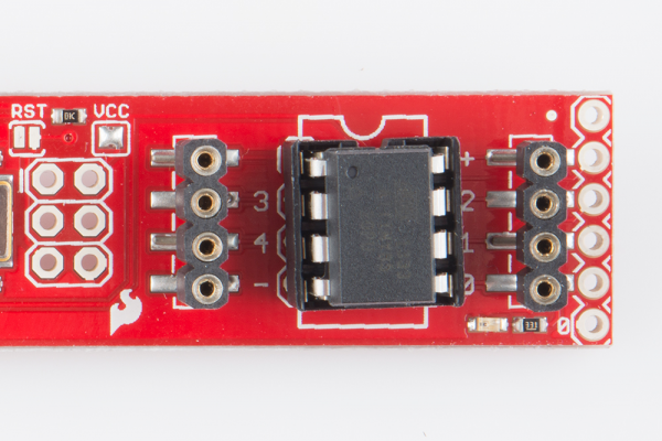
A Tiny AVR Programmer with an ATtiny85 inserted.
When plugging your ATtiny into the socket, take note of the notch on both the socket and the white silkscreen on the PCB. This should match the polarity of the ATtiny85. Usually the ATtiny85 has a dot next to pin 1 of the IC, this should be placed up towards the notch.
The +, -, and numerical labels on the side of the socket reference the pin numbers and voltage supply inputs of the ATtiny85. These pin numbers can be called in the Arduino IDE as we’ll show later in this tutorial.
The 4-pin headers on either side of the socket help for prototyping the ATtiny85 out to external circuitry. You can easily plug male jumper wires into these pins, which can be routed to breadboards or other prototyping circuits.

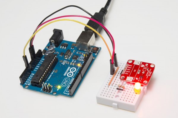
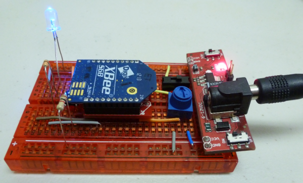
An ATtiny85 being prototyped out to a potentiometer (analog input), button (digital input), and RGB LED (analog/digital output).
Finally, there’s an on-board amber LED connected to pin 0 of the ATtiny85. This is super-helpful when you’re uploading the “Hello, world” blink sketch to an ATtiny85.
That covers the fundamental stuff on the Tiny AVR Programmer. If you plan on doing more advanced stuff with the board, or just want to know more, feel free to read on. Otherwise, skip ahead to the next page.
Output Programming Pins
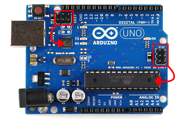
The Tiny ISP Programmer is not limited to ATtiny85’s. It’s a full-fledged AVR programmer. This row of six pins can be connected to other AVRs via the standard 2x3- or 2x5-pin ISP headers. You could, for example, connect these pins to your Arduino Uno, Leonardo, etc. to re-flash a bootloader, or upload code using a programmer.
Refer to the pin labels in the image above if you’re connecting the Tiny AVR Programmer to another AVR chip. Most AVR development boards break out either a 2x3 or 2x5 programming header, which have the following pin-outs:

Just match up the labels on the Tiny Programmer to the pins on your AVR board/chip, and get ready to program!
The Jumpers
There are two jumpers on the top side of the Tiny AVR Programmer. One is labeled RST and the other is VCC. A little bit on each of those:
The VCC jumper is normally closed. It controls the flow of power to the socketed ATtiny85. As long as the jumper remains closed, the tiny85 will be powered by 5V from the Tiny AVR Programmer’s USB port. If the jumper is opened, you’ll need to supply an external power source for the ATtiny85. (This all pertains to the 5V pin on the output programming header too.)
If you need to power the ATtiny85 at some voltage other than 5V or just need it to be on an isolated supply, consider grabbing some solder wick to desolder the jumper, and supply your own voltage source.
The RST jumper is more advanced. This header connects the ATtiny84’s reset pin to the to the 2x3-pin ISP header in the middle of the board. The Programmer ships with this jumper open. If you ever need to reprogram the ATtiny84 (which, for standard use cases, you shouldn’t), you’ll have to close this jumper to enable programming it.
Enough talk. Let’s start using the programmer. On the next few pages we’ll cover driver installation (for Windows users) and show how you can use the Tiny AVR Programmer to program an ATtiny85 in Arduino.
Driver Installation
Before you can start using the Tiny AVR Programmer, you may need to set it up on your computer. If you’re using a Mac or Linux machine, you don’t need to install drivers. Just plug the board in, and skip to the Programming in Arduino page.
If you’re using any version of Windows, you’ve got a few steps to follow before you can join your Mac/Linux comrades:
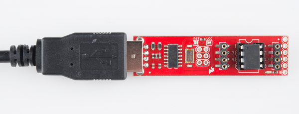
Step 1: Plug the Programmer In
To begin, locate an empty USB port on your computer, and plug the Tiny AVR Programmer into it. You’ll probably want to have the programmer close by. If you’re using a PC, or your USB ports aren’t close by, a USB Extension Cable might help get the programmer into a more convenient spot on your desk.
Step 2: Wait for Windows to Automatically Fail/Succeed
After plugging in your Tiny AVR Programmer, Windows will try to look for a driver that matches it. Keep an eye on the notification area in the bottom-right corner. Wait for Windows to try to install the driver on its own. There’s a chance that, after searching, Windows will find the driver. If you get a Device driver software installed successfully notification (lucky you!), you can ignore the next few steps. But, if you got something like this:

Continue on to step 3…
Step 3: Download the Driver
If Windows couldn’t find the driver for you, you’ll need to download it. There are two versions, make sure you grab the one that matches your system:
After downloading your driver, extract it from the zip folder. Don’t forget where you put it!
Step 4: Open the Device Manager
To install the driver, you’ll need to first open up the Device Manager. From the Control Panel, go to the System and Security section, click System, and click on Device Manager. (Alternatively you can Rundevmgmt.msc).
In the Device Manager, open up the LibUSB-Win32 Devices tree and you should find a USBTinyProgrammer with a yellow warning triangle hovering over the icon.
Right-click on the USBTinyProgrammer device, and select Update Driver Software…

Step 5: Driver Pointing
On the Update Driver Software window that appears, select Browse my computer for driver software.
On the next window, Browse for driver software on your computer, set the driver search location to the folder you downloaded and unzipped in step 3. The folder should be named something like usbtinyisp_libusb-win32_1.2.1.0:
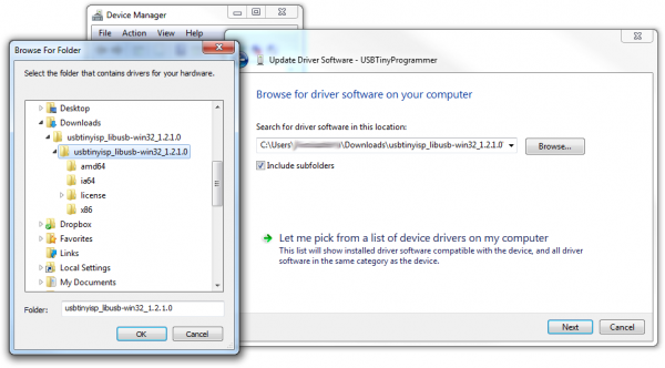
Then click Next, and the driver will begin updating. Shortly after that, though, a Windows Security window should pop up to let you know the driver isn’t “signed”. Click Install this driver software anyway. We promise it won’t damage your computer!
Then play the waiting game for a moment, and wait for a happy Windows has successfully updated your driver software window.
After closing that success window, your Device Manager should have an entry for USBtiny under LibUSB-Win32 Devices.
Programming in Arduino
Everyone loves Arduino! The simplified language makes programming AVRs and more complicated microcontrollers incredibly easy. Unfortunately, Arduino doesn’t have any built-in functionality to program tiny AVRs, but that doesn’t mean we can’t add it!
On this page we’ll go over all of the steps necessary to enable ATtiny45/85 programming in Arduino, using the Tiny AVR Programmer.
Step 0: Install Arduino
If you’ve never used Arduino before (where have you been?!), make sure you follow our What is an Arduino? and Installing Arduino tutorials before continuing on.
Step 1: Download the ATtiny Addon
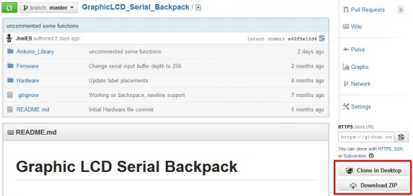
To add ATtiny’s to the standard Arduino IDE Board menu, you’ll need to add a few files that help define the hardware. The ATtiny hardware definitions are kept in a repository on GitHub. You can download them from there, or simply click here to download them in a ZIP folder.
Extract the ZIP folder, and don’t forget where you put it!
Step 2: Move the attiny Folder
There should be an attiny folder living within the attiny-master folder you downloaded. Copy that folder and paste it into a hardware folder within your Arduino Sketchbook directory.
If you’re not sure where your Arduino sketchbook is, open Arduino and go to File>Preferences. The Sketchbook location should be the topmost entry in the Preferences dialog. By default, the sketchbook is usually an Arduino folder within your home folder (e.g. C:\Users\userName\Arduino on Windows, or /Users/userName/Documents/Arduino on Mac).
If there’s not a hardware directory already in your Sketchbook make one. After placing the attiny folder in there, your directory structure should look a little something like this:

Step 3: Open and Configure Arduino
Almost to the fun part! Open Arduino. If you opened Arduino in the last step, close it and restart it.
Under the Tools>Board menu, you’ll find the effects of the attiny folder. There should be twelve new entires in the board list, which allow you to program ATtiny45’s, 85’s, 44’s and 84’s. Each microcontroller can be set to a variety of clock speeds – internal 1MHz or 8MHz or external 20MHz.
If you’re using a bare, previously untouched ATtiny85 select ATtiny85 (internal 1 MHz clock). Be careful selecting here, selecting the 8 MHZ option will only make your sketch run slow, but selecting the 20 MHz option can “brick” your ATtiny. Do not select the 20 MHz option unless you have an external clock attached!

Unlike other Arduino boards, you don’t have to select a Serial Port when using the Tiny AVR Programmer. But you do need to select a Programmer. Under the Tools>Programmer menu, select USBtinyISP.

Step 4: Plug in the ATtiny
Getting close to blinking! When you plug the ATtiny into your Programmer, make sure you get the polarity correct. The small, etched circle on the IC should line up with the “notch” on the Programmer’s socket and silkscreen.
To get the IC into the socket, you may need to bend the legs on each side inwards a tad.
Step 5: Upload Code!
Time for the Blink sketch! The Tiny AVR Programmer has an on-board LED, connected to the ATtiny, which we can use to verify that code on the IC is running. The LED is connected to pin 0 in the Arduino environment. Copy/paste this code into your Arduino window:
language:c
int blinkPin = 0;

void setup()
{
  pinMode(blinkPin, OUTPUT);
}

void loop()
{
  digitalWrite(blinkPin, HIGH);
  delay(500);
  digitalWrite(blinkPin, LOW);
  delay(500);
}
Then click Upload just as you would with any Arduino board. The code will compile, and then it should upload insanely fast. That’s the wonders of direct in-system programming for you.
If successful, the on-board amber LED should start blinking.
ATtiny85 Use Hints
The ATtiny85 isn’t your everyday Arduino IC. It packs a lot of punch for its small size, but there are some things it can’t do.
On this page, we’ll provide a quick overview of the ATtiny85 as it pertains to Arduino and the Tiny AVR Programmer.
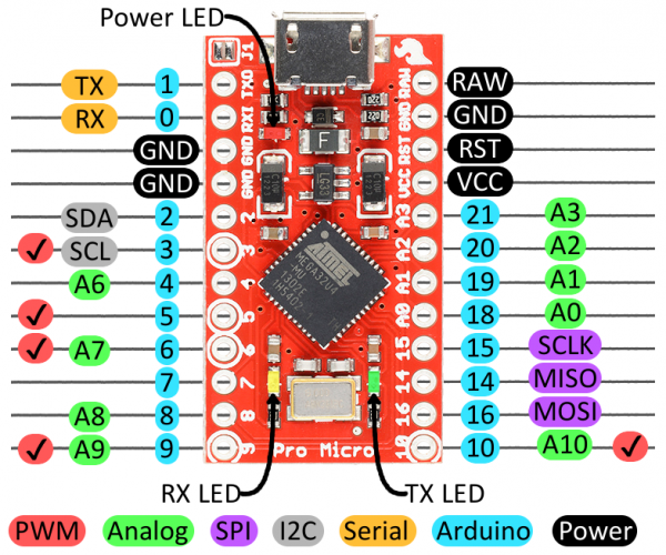
Pinout
Just like any Arduino board, each I/O pin on the ATtiny85 is assigned a numerical identifier. These pins are documented on the board as well, but you can also refer to the image below if you forget.

Each of the I/O pins on the ATtiny85 are capable of digital input and output. Beyond that, some pins have special functionality.
Analog Input and Output
There are two analog outputs and three analog inputs. Use them just as you would with any Arduino board. Use analogWrite([pin], [0-255]) to do PWM output. This functionality is available on pins 0 and 1. For example:
language:c
int pwmPin = 0;

pinMode(pwmPin, OUTPUT);

for (int i=0; i<=255; i+=5)
{
  analogWrite(pwmPin, i);
  delay(5);
}
And use analogRead([pin]) to read an analog voltage between 0 and 5V, and turn it into a 10-bit representation of that voltage. Pins 2, 3, and 4 are capable of analog input, but, when using them as such, they should be referenced as A1, A3, or A2 respectively. For example:
language:c
int pwmPin = 0;
int analogInPin = A1;

pinMode(pwmPin, OUTPUT);
pinMode(analogInPin, INPUT);

int analogIn = analogRead(analogInPin); // Read analog voltage on pin 2 (A1)

analogWrite(pwmPin, analogIn / 4); // Output analog reading to dimmable LED
No Serial (UART). Yes SPI and I2C.
You may notice, on the listing of special pin functions there are no UART RX’s or TX’s. That’s because the ATtiny85 doesn’t have a built in hardware UART. If you try to compile any Arduino code with Serial.begin(9600)’s or Serial.print()’s you’ll get an error.
So you’re out one of the more useful Arduino debugging tools. You can’t print to the Serial Monitor. But the ATtiny85 does still have I2C and SPI, which are much more commonly used for sensor communication these days. Unfortunately, the Arduino libraries for these interfaces haven’t yet been written for the ATtiny85, but there are some user contributed libraries around the web. USIi2c is an Arduino library which enables I2C on the ATtiny85.
There are other ATtiny85-focused libraries out there too. Like a Servo8Bit, a servo library.
Prototyping with the Tiny AVR Programmer
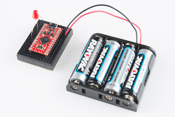
There’s only so much excitement you can get out of dimming a single, yellow LED. You’ll eventually want to branch out, and start connecting your tiny85 to other electronic components. There are a few ways to do this.
The easiest, least permanent prototyping route is to use the prototyping headers on either side of the socket. You can connect standard, male jumper wires to these pins, which can in turn be routed to breadboards or other components.
For more permanent projects, it’s easy enough to gently remove the IC from the socket, and plug it into a PCB or breadboard. Eventually, once you’ve iterated enough on your sketch, this is probably where you’ll want to go. Eventually you arrive at finished designs like the H2OhNo! or the LectroCandle.
Resources & Going Further
Resources
Tiny AVR Programmer Design Files
- Schematic– A PDF of the Tiny AVR Programmer’s schematic.
- Eagle Files– If you want to look at the PCB design, or modify it to make a version of your own, check these files out.
- Tiny AVR Programmer Firmware– If you want to dig into the code that lives on the Programmer itself, check this out.
- GitHub Repository– Go here to find the latest, greatest version of the Tiny AVR Programmer’s hardware and firmware. Or modify it and contribute your changes back!
Drivers, etc.
- Arduino Board Definitions– The attiny folder should live within a hardware folder in your Arduino sketchbook.
- 32-bit USBTinyISP Driver– Windows driver for 32-bit systems
- 64-bit USBTinyISP Driver– Windows driver for 64-bit systems
ATtiny85 Resources
- Atmel Documentation Page– The latest datasheets and application notes for the ATtiny85.
- High-Low Tech Tutorial– An overview of programming the ATtiny85 using Arduino.
Going Further
- H2OhNo!– The H2OhNo! water alarm and development board uses an ATtiny85 to sense the presence of water. This tutorial goes deep into getting the ATtiny85 into a very low power mode.
- Shift Registers– If you’re feeling restrained by the ATtiny’s lack of pins, you may be able to use a shift register to expand on that I/O count.
- Using the Arduino Pro Mini 3.3V– If you’re looking for small, but need more pins and functionality check out the Arduino Pro Mini.
- Installing an Arduino Bootloader– You can use the Tiny AVR Programmer to program all sorts of AVRs, including those on most Arduino-compatible boards. If you ever find yourself needing to reprogram your Arduino bootloader, the Tiny AVR Programmer should be all you need.
learn.sparkfun.com |CC BY-SA 3.0 | SparkFun Electronics | Boulder, Colorado


![[UnoR3]](http://dlnmh9ip6v2uc.cloudfront.net/images/products/11021-01a_l_th.jpg)
![[UnoSMD]](http://dlnmh9ip6v2uc.cloudfront.net/images/products/10356-01b_l_th.jpg)
![[RedBoard]](http://dlnmh9ip6v2uc.cloudfront.net/images/products/1/1/5/7/5/11575-01_small.jpg)
![[Pro 3V]](http://dlnmh9ip6v2uc.cloudfront.net/images/products/10914-01_l_th.jpg)
![[Pro 5V]](http://dlnmh9ip6v2uc.cloudfront.net/images/products/10915-01_l_th.jpg)
![[Mini05]](http://dlnmh9ip6v2uc.cloudfront.net/images/products/11303-01a_l_th.jpg)
![[ProMini3]](http://dlnmh9ip6v2uc.cloudfront.net/images/products/1/1/1/1/4/11114-01_l_th.jpg)
![[ProMini5]](http://dlnmh9ip6v2uc.cloudfront.net/images/products/1/1/1/1/3/11113-01d_l_th.jpg)
![[Arduino Ethernet]](http://dlnmh9ip6v2uc.cloudfront.net/images/products/1/1/2/2/9/11229-01_i_ma.jpg)
![[Fio]](http://dlnmh9ip6v2uc.cloudfront.net/images/products/10116-01_l_th.jpg)
![[LilyMain]](http://dlnmh9ip6v2uc.cloudfront.net/images/products/09266-01_l_th.jpg)
![[LilySimp]](http://dlnmh9ip6v2uc.cloudfront.net/images/products/10274-01c_l_th.jpg)
![[Leo]](http://dlnmh9ip6v2uc.cloudfront.net/images/products/11286-01_l_th.jpg)
![[ProMicro5]](http://dlnmh9ip6v2uc.cloudfront.net/images/products/11098-01a_l_th.jpg)
![[ProMicro3]](http://dlnmh9ip6v2uc.cloudfront.net/images/products/10999-01_l_th.jpg)
![[LilyUSB]](http://dlnmh9ip6v2uc.cloudfront.net/images/products/1/1/1/9/0/11190-01a_small.jpg)
![[2560R3]](http://dlnmh9ip6v2uc.cloudfront.net/images/products/11061-01a_l_th.jpg)
![[MegaPro3]](http://dlnmh9ip6v2uc.cloudfront.net/images/products/10744-01_l_th.jpg)
![[MegaPro5]](http://dlnmh9ip6v2uc.cloudfront.net/images/products/11007-Error-01_l_th.jpg)
![[MegaProMini]](http://dlnmh9ip6v2uc.cloudfront.net/images/products/10743-01_l_th.jpg)
![[Due]](http://dlnmh9ip6v2uc.cloudfront.net/images/products/1/1/5/8/9/ArduinoDue_small.jpg)