Quantcast
Channel: SparkFun Tutorials
Viewing all 1123 articles
Browse latest View live

Electric Imp Breakout Hookup Guide

$
0
0

Electric Imp Breakout Hookup Guide a learn.sparkfun.com tutorial

impRoduction

The electric imp is a deviously awesome development platform. Disguised as an every day SD card, the imp is actually a unique combination of microprocessor and WiFi module. The imp makes connecting any device to the Internet a breeze. Looking to catch on with this “Internet of Things” fad? The imp is an excellent place to start.

The electric imp card

The electric imp card. (Note: We didn’t misplace the copywriter, electric imp is their brand convention.)

In this tutorial, we’ll be explaining how to use the imp with one of our Breakout Boards. This simple PCB assembly houses the bare minimum you might need to get an imp up-and-running. First, we’ll cover how to hook up the hardware end of the imp/Breakout combo. Following that we’ll head over into the firmware domain, programming the imp to blink LEDs and read analog and digital inputs. The last code example shows off the coolest part of the imp: controlling hardware over the Internet!

The electric imp Breakout

The electric imp Breakout Board.

Requirements

Of course, you’ll need an imp and a Breakout Board. Aside from those two parts, we’ll use a few common electronics parts you may already have. Here’s a wishlist of everything we’ll be using. If you’d like to use some parts you may already have around the house


In addition to those items, you’ll also need the following non-SparkFun materials:

  • Wireless network with Internet access
  • electric imp planner account (sign up is free/easy)
  • electric imp planner website pulled up in your web browser
  • SmartPhone w/ the electric imp app (Android or iOS)

Tools

There will be some soldering involved. The Breakout Board does not come with header pins soldered on, which you’ll need in order to interface with the imp’s I/O pins. You’ll need a simple soldering iron and a bit of solder. (If you’ve never soldered before, this is a great place to start! The solder points are easy, through-hole jobs.)

Before We Begin

This tutorial builds upon some basic electronics concepts. If you aren’t familiar with any of the topics below, consider reading through that tutorial first:

Aside from the imp’s programming language, Squirrel, there will be a variety of coding languages used in later parts of this tutorial – primarily HTML and Javascript. Don’t worry if you’re not too familiar with those, as the examples aim to be short, sweet, and easy-to-modify.


Let’s start by overviewing the imp card itself. It’s hard, at first, to wrap your head around the fact that this little, white SD-looking card is actually a powerful WiFi-enabled microcontroller platform.

About the imp

It may look like an everyday SD card, but the electric imp is much, much more. It's a WiFi-enabled microprocessor. It’s programmable over the air. It’s got GPIOs, UARTS, I2C and SPI interfaces, pulse-width-modulation, digital-to-analog and analog-to-digital converters. Basically, it’s what you’d get if you smushed an ARM microprocessor and a WiFi module down into a tiny SD-card-sized package.

imp card boxed up

The imp provides an easy, integrated way to connect almost any hardware device to Internet services. It is well suited to be the backbone of your Internet-enabled project, whether you’re remotely controlling your electric blanket or triggering an irrigation system via a web browser. Connecting your imp to a wireless network and programming it is a simple, streamlined process.

The Hardware: 6 Wondrous I/Os

The imp is basically made of pure awesome. But, if we lift the hood of awesomeness for a moment, we can talk a bit about the imp's hardware. The platform of the electric imp is a Cortex-M3 microprocessor. Just like any microprocessor, the imp has a collection of input and output pins, each with unique functions. There are six addressable I/O pins – not as many as an Arduino, but it makes up for it in terms of functionality. The imp has three UARTs, two I2C and SPI interfaces, and two DAC outputs; plus each pin can act as an ADC input and PWM output.

Table from Imp's Wiki Page
Pin #UART1289UART57UART12I2C89I2C12SPI257SPI189DACADCPWM
1CTSTXSCLSCLKYesYesYes
2RTSRXSDAMISOYesYes
5TXSCLKYesYesYes
7RXMOSIYesYes
8TXSCLMOSIYesYes
9RXSDAMISOYesYes

Of course, each of those pins can also be used as a simple inputs (with or without pull-up resistors) or outputs, sinking/sourcing up to 4mA each.

Also in that tiny SD package is a WiFi module, an antenna, and a light sensor. We’ll find out why the light sensor is critical in the coming pages.

The imp is a 1.8-3.3V device, supplying it any more voltage than that can be harmful. It can require up to 400mA (worst-case), but it’ll usually pull about 80mA (even 5mA in a power-save mode).

The IDE: The imp Planner

All code written for the imp is done online, in a web browser. The integrated development environment (IDE) for the imps is called the planner. Everyone can (freely) create their own account on the planner, where both your programs and your imps are kept safe and secure. There are certainly pros and cons to this “always online” approach (though you can write and save every program locally, and upload it when you’re ready). Still, it seems like a good solution for this type of platform.

A screenshot of the imp planner

Code in the planner is divided into two halves: the imp device, and the agent. Code in the device half is code that actually runs on your imp. The agent is a process living on electric imp’s cloud server. It can communicate with both your imp, and the outside Internet world. We’ll dig further into the differences between these two components later.

The Language: Squirrel

Firmware for the imp is written in a language called Squirrel. Squirrel is an object oriented language similar to Javascript, but unlike most embedded system programming languages we’ve encountered (namely Arduino). Entering imp development from the world of Arduino may be somewhat jarring. There are no loop() or setup() functions, instead most actions are event or timer-driven.

Example of squirrel language

There are tons of great examples on electric imp’s wiki page, and if you're truly interested in learning Squirrel, check out the Squirrel homepage. There’s also the Electric Imp API to familiarize yourself with. These are functions and libraries used to perform actions with the imp’s GPIO pins and other hardware functionality.

About the Breakout

In order to use an electric imp, two pieces of hardware are required: the imp card and the impee. An impee is the piece of hardware that houses the imp. Aside from having a standard SD socket for the imp to slide into, the impee also needs to provide power to the imp, and do something with the imp’s I/O pins. Our impee for this tutorial is as simple as it gets…a breakout board.

Top/bottom view of imp breakout

Top and bottom views of the imp breakout.

The imp breakout provides the bare minimum you should need to add an electric imp to your project. There’s an SD socket, a step-down voltage regulator, and every I/O pin of the imp is broken out to a 0.1"-spaced header.

Powering the Breakout

A big chunk of the circuitry on the Breakout board is a 3.3V TPS62172 step-down regulator (and the inductor/capacitors supporting it). This regulator allows for input voltages anywhere between 3.3V and 17V (voltages in the upper end of that range may produce some heat). It can support up to 500mA of continuous current.

There are three power inputs on the board, all of which, are fed into the on-board 3.3V regulator:

  • “VIN” header - This standard 0.1" header feeds directly into the 3.3V regulator.
  • Battery input - These are the pins and pads labeled “+” and “-”. The footprint of the two through-hole pins matches up to a PTH 2-pin JST connector, which mates with our LiPo batteries (or AA batteries). This input needs to be selected using the jumper (see below).
  • USB mini-B connector - This power input should feed a clean, 5V source into the breakout board’s regulator. The USB voltage supply can come from either a mini-B cable connected to your computer or a USB wall adapter. This input needs to be selected using the jumper (see below).

Where the power inputs are

Setting the Jumper

To use either the battery or USB power inputs, a jumper must be set on the board. To use the jumper, first solder a 3-pin male header to the jumper pins. Then use a 2-pin jumper to span from the middle pin, to whichever of the two inputs you’d like to use.

Jumper set to USB

In this image, the jumper is set to apply USB power to the imp breakout. A JST connector was soldered to the battery input pins, in case we want to use a LiPo to power the board.

The Breakout’s Schematic

There are three main components to the breakout board: a TPS62172 step-down regulator (U2), the electric imp socket (U1), and the ATSHA204 authentication chip (U3).

Electric Imp Breakout Schematic

electric imp Breakout Schematic. Click the image to get a larger picture, or click here to view the schematic as a PDF.

Pinout

All of the imp’s GPIO pins are broken out to the 0.1"-spaced header, along with a few related power pins:

  • GND - Common pin for input voltage.
  • VIN - Input voltage supply fed into regulator.
  • PIN1 - imp pin 1 (DAC, UART1289 CTS, UART12 TX, I2C12 SCL, SPI189 SCLK)
  • PIN2 - imp pin 2 (UART1289 RTS, UART12 RX, I2C12 SDA, SPI257 MISO)
  • PIN5 - imp pin 5 (DAC, UART57 TX, SPI257 SCLK)
  • PIN7 - imp pin 7 (UART57 RX, SPI257 MOSI)
  • PIN8 - imp pin 8 (UART1289 TX, I2C89 SCL, SPI189 MOSI)
  • PIN9 - imp pin 9 (UART1289 RX, I2C89 SDA, SPI189 MISO)
  • CD - Card detect. This signal will connect to GND whenever a card is inserted into the socket.
  • 3V3 - 3.3V output from regulator.
  • GND - Common ground.

ID Chip

There’s actually one more piece of hardware required of the impee: an ID chip, which provides each impee with a unique identification code. This means that every impee you encounter should include an Atmel ATSHA204 authentication chip. The imp automatically interfaces with this chip every time it boots up, so it can identify which impee it’s plugged into. This actually turns out to be pretty awesome, because the program that an imp runs depends on what impee it’s plugged into. If you had two impees in your house – say controlling an irrigation system and another controlling a coffee machine – one, single imp would run two different programs depending on which machine it was plugged into.

You shouldn’t ever have to fuss with the ID chip. In fact, you can forget we ever said anything about the ATSHA204!

Hardware Hookup

The hardware hookup approach in this guide is just one of many ways to use the board. The breakout is made to be a versatile extension of the imp. You can connect whatever you want to the imp pins, and power the board however your project requires.

Solder Headers

In order to do much with the input/output capability of the imp, you’ll need to solder to the broken out pins. If you want to use the imp Breakout with a breadboard or perfboard, 0.1" male headers make for a good choice. Depending on your application, you could swap the headers with wire, female headers, screw terminals, or a variety of other connectors.

We’re going to solder male headers into the board, so we can use it with a breadboard later on.

Headers soldered on to breakout, inserting into breadboard

Apply Power

Depending on what you want to use for your power source there are a few options here. You could use the on-board USB connector. Or you could solder down a 2-pin JST connector, and plug battery (LiPo or AA) into the board to make it mobile. If you go with either of those options, you’ll also need to set the jumper.

Jumper set to USB power

Note how the jumper is set. We’re using USB to power the imp in this picture.

Alternatively, you can apply power straight to the headers labeled “VIN” and “GND”. This pin bypasses the jumper and goes straight to the regulator.

Plug in the imp!

Nothing too complicated about this part. Plug the imp card in so the suspicious little imp logo is facing up.

If you’ve got power to the board, once plugged in, the imp should start blinking orange. If there’s no blinking on the card, it’s probably not getting any power. Double-check that the jumper is set correctly.


What’s all that blinking signify? How do we get the imp connected to our wireless network? Read on!

BlinkUp

Blink Codes

The imp has an internal red/green LED, which is used to tell the world what state it’s currently in. If you’ve just plugged the imp in, and haven’t told it how to get on your WiFi network, it should be blinking orange (red/green simultaneously). Here are the rest of the codes to look out for:

imp blink codes (from the imp dev wiki)
ColorSpeedimp State
Orange1 HzNo WiFi settings
GreenSingle PulseSuccessfully received configuration via Blinkup.
RedTriple-pulseFailed to receive configuration via Blinkup.
Red1 HzAttempting to connect to WiFi.
Red, Orange, Off1 HzGetting IP address (via DHCP).
Orange, Red, Off1 HzGot IP address, connecting to server.
Green0.5 HzConnected to cloud (turns off after 60 seconds).
Red2 HzConnection lost, attempting to reconnect.
NoneNormal operation

Let’s make that LED blink green! Time to send a BlinkUp.

BlinkUp

To get your imp connected to your WiFi network as well as the online imp servers, you need to go through the process electric imp calls commissioning. There’s a great write-up on the commissioning process over on electric imp’s wiki page. Here’s the gist of it, as well as a few tips.

Before you begin, you’ll need to make an Electric Imp account, by visiting the planner page.

Updating the imp with your WiFi credentials is a unique process. The imp card has a built-in light-sensor, looking out of the little window on the short, flat edge of the imp. The light-sensor can be used to process small amounts of precisely modulated data in the form of a blinking light.

The edge of the imp card where the light sensor window is

To generate this blinking light, you need the electric imp app installed on your smartphone (iOS or android). Go download that app if you haven’t already!

Follow the directions in the app, and prepare to update the imp with your WiFi network. Then, when your settings all look correct hit the Send BlinkUp button. Then quickly place the screen of the phone as close to the imp’s light sensor as possible.

BlinkUp in action

Avert your eyes! Unless you enjoy staring into bright, white strobing lights.

If all goes well, there should be a very short green blip of the LED, followed by a few blinks of red and orange. When the imp starts blinking green once a second, you know you’ve got your imp commissioned yay!

Troubleshooting

If you’re imp isn’t yet in the blinky green phase, use the LED blink codes to find out where it’s failing. Here are some recommended steps, depending on the failure point:

  • Connecting to the server (orange, red, off) - Make sure there’s no firewall blocking the imp’s way to the Internet (and make sure your WiFi network has an Internet connection in the first place).
  • Getting IP address via DHCP (red, orange, off) - Double check your WiFi password.
  • Attempting WiFI connection (red) - Double check your WiFi network name (SSID).

If all of the above are set correctly, try sending the BlinkUp one more time. We’ve found that it helps to close out all other app, or even try resetting your phone if it continues to fail.

You can also try turning off the room lights for a moment. Pinching the imp, just above and below the light-sensor window can help as well.

Example 0: Hello World

Now that your imp is commissioned, it’s time to upload your first bit of code!

As with any new development platform, our first goal is to make sure we can make an LED blink. If you can make an LED blink, you’re well on your way to spinning motors or communicating with sensors.

Using the IDE

To begin, go to electric imp IDE, and log in if you haven’t already.

If your electric imp was successfully commissioned, and your breakout board is still powering it, you should see a tab labeled _New Devices [1]- on the left-hand side. Expand that and click on the random-looking hexadecimal string.

Adding a new device screenshot

That should prompt a Device Settings lightbox to pop up. Here you can give your impee (the Breakout Board) a name. Something more identifiable than the 64-bit random string it’s got right now. We’ll also associate it with a new model. In that drop-down menu/text box type Hello, blink, and create a new model. Then click Save Changes.

Naming and new model

Now, on the left side, you should see a new tab called Hello, blink. Select than, then click your impee name. This is the standard view of the imp IDE. It’s split into three sections:

  1. Device– This is the code that your imp runs. This is where you do all of your hardware control, like writing pins high and low, or reading inputs.
  2. Agent– This is code that runs external to your imp, in the cloud. You can offload server tasks, like HTTP requests, here. There are built in functions to aid in communication between imp and agent.
  3. Log– This is where messages and errors are printed (using the server.log() function).

Blank imp IDE

Now we’re ready to load some code, and blink some LEDs!

The Circuit

The circuit for this example is very simple. We only need to connect an LED to pin 1. Don’t forget your current-limiting resistor!

LED connected to pin 1

Any of the imp’s I/O pins would work for this example. After working with the code, see if you can modify it to blink on other pins (or all of them!).

Hello, blink Code

We’ll only be working with the Device portion of the IDE right now. Copy and paste the code below into the middle section of your window.

language:squirrel
/* Hello, Blink
   by: Jim Lindblom
   SparkFun Electronics
   date: October 31, 2013
   license: Beerware. Use, reuse, and modify this code however you see fit.
   If you find it useful, buy me a beer some day!

   This is an Electric Imp hello, world blink sketch. It'll blink an LED
   connected to pin 1, once every second.
*/

////////////////////////////////////////
// Global Variables                   //
////////////////////////////////////////
ledState <- 0;

////////////////////////////////////////
// Function definitions               //
////////////////////////////////////////

// Loop constantly updates the LED. If ledState is 1, we'll turn the LED on and
// set ledState to 0. Vice-versa is ledState is 0 coming in. This function
// schedules a wakeup in 1 second, and calls itself again.
function loop()
{
    if (ledState)
    {
        hardware.pin1.write(1); // Write pin 1 high
        ledState = 0; // Flip ledState
    }
    else
    {
        hardware.pin1.write(0); // Write pin 1 low
        ledState = 1; // Flip ledState
    }

    // This must be called at the end. This'll call loop() again in 1s, that way
    // it'll actually loop!
    imp.wakeup(1.00, loop);
}

////////////////////////////////////////
// Setup Stuff: Runs first at startup //
////////////////////////////////////////
hardware.pin1.configure(DIGITAL_OUT);   // Configure Pin 1 as digital output

loop(); // Call loop, and let the program go!

Then hit the >Build and Run button up top, and enjoy the blinks.

Shortcut heads up! If you’re a neurotic CTRL+S saver, the standard save shortcut doessave, but it also attempts to build and run your code. If successful, it’ll upload the code and immediately start running on your imp. If there’s an error, you’ll start hearing about it in the log window.

Into the Code

If you’re only used to working with Arduino sketches, this code may make very little sense, electric imp programs have a very different “flow” to them. Begin by looking at the 2 lines of code at the bottom (under the “Setup Stuff” header). This is actually where our imp starts when it begins to run it’s program. Everything above is simply a function or variable definition.

The majority of this code deals with the imp’s pin class, which handles all of the I/O control. If you’re used to using Arduino GPIO’s, the imp’s API isn’t too different. You have to set the pin up as either an input or output, analog or digital. Then write or read to the pin accordingly.

At the end of the setup, we make a call to a loop() function, which is defined above. loop() is simple, it checks a global variable named ledState. If ledState is 1 we turn the LED on, if it’s 0 we turn the LED off.

To write a pin high or low, we call the hardware.pin1.write([0:1]) function. You can probably extrapolate from that how to control the other five pins.

The special sauce making loop actually loop is the last line of code in the function: imp.wakeup(1.00, loop). The imp.wakeup function puts the imp to sleep, but sets a timer. When the timer goes off, the requested function (loop in this case) function is called from its beginning. In this case we set the timer to 1.00 seconds, so loop() should run once a second. This is really the only way to make the electric imp “loop” like an Arduino might.

Check out the comments in the code for a more in-depth overview of each function call. Or, for more information, check out electric imp’s API reference.

Example 1: I/O Control

The electric imp can do most anything an Arduino or similar microcontroller can. It’s got analog-to-digital converters, PWM, SPI, I2C, UARTs, and it even has digital-to-analog converters. In this snippet of example code, we’ll dig further into the imp’s I/O control delving into digital and analog input/output.

Example 1 circuit image

The Circuit

The setup for this example code requires three unique components: an LED, potentiometer, and a button (plus a current-limiting resistor for the LED). Here’s a fritzing diagram and schematic (click to see it bigger) for our circuit:

Example 1 Fritzing diagram and schematic

Make sure the imp is getting power. USB is usually the quickest/easiest way to apply power to the breakout board, but you’ll need to set the jumper accordingly.

The IDE

To create a new piece of code, we need to create a new “model” and associate it with our Breakout Board impee. To do this, hover over your impee and click the “settings” gear. The familiar Device settings window should pop up. Under the Associated model: box, create a new model named I/O Control. Then click Save Changes_.

Assigning the impee to a new model

This will create a new tab on the left side labeled I/O Control. If you expand that tab, you’ll see that the Breakout Board impee has be reassigned there.

The Code

Once again, we’ll only be using the Device portion of the IDE. Copy and paste everything from the below box, into your Device window and click Build and Run up top.

language:Squirrel
/* Digital Input, Analog Input, PWM Output Example
   by: Jim Lindblom
   SparkFun Electronics
   date: July 15, 2013
   license: Beerware. Use, reuse, and modify this code however you see fit.
   If you find it useful, buy me a beer some day!

   This is a simple piece of code which uses an LED, potentiometer, and button.
   The LED connects to pin 1 through a 47 ohm resistor. The cathode of the LED should connect to ground.
        This means writing pin 1 will turn the LED on, and writing it to 0 turns the LED off.
   The button connects on one side to pin 9, and the other pin of the button goes to ground.
        We'll use the internal pull-up resistors on pin 9 to bias the button high.
        When the button is pressed, pin 9 should read as low.
   The wiper of the potentiometer is connected to pin 5. The other two pins of the pot should be
        connected to +3.3V and GND. This'll make the voltage at pin 5 adjustable from 0-3.3V.
*/

////////////////////////////////////////
// Function definitions               //
////////////////////////////////////////

local ledState = 1; // Says local, but think of this as a global var. Start with LED on

// function pin9Changed() will be called whenever pin 9 goes from high->low or low->high
function pin9changed()
{
    local buttonState = hardware.pin9.read(); // Read from the button pin

    if (buttonState == 0) // Button will read low if pressed
    {
        ledState = ledState ? 0 : 1;    // Flip flop ledState
        server.log("Button pressed!");
    }
    else // Otherwise button was released, no action
    {
        server.log("Button released");
    }
}

// Loop constantly updates the LED. If ledState is 1, we'll read the pot, and set the LED brightness accordingly.
// If ledState is 0, we'll just turn the LED off. ledState is updated in the pin9Changed() function.
function loop()
{
    if (ledState == 1)
    {
        local rawValue = hardware.pin5.read();  // Read from the potentiometer. Returns a value between 0 and 65535.
        rawValue /= 65535.0;  // Make rawValue a % (and a float). The pin write function requires a value between 0 and 1.
        hardware.pin1.write(rawValue);  // Pin 1 is already configured as PWM, write potentiometer value
    }
    else
    {
        hardware.pin1.write(0);  // Write pin 1 low -- LED off
    }

    // This must be called at the end. This'll call loop() again in 10ms, that way it'll actually loop!
    imp.wakeup(0.01, loop);
}

////////////////////////////////////////
// Setup Stuff: Runs first at startup //
////////////////////////////////////////
hardware.pin1.configure(PWM_OUT, 0.0005, 0.0);   // Configure Pin 1 as PWM output, 5ms period, 0% high (off)
hardware.pin5.configure(ANALOG_IN); // Configure pin 5 as analog input
hardware.pin9.configure(DIGITAL_IN_PULLUP, pin9changed); // Configure pin 9 as digital input (with pull-up enabled). On change it'll call function pin9changed().
imp.configure("LED Trigger Wiper", [], []);

loop(); // Call loop, and let the program go!

The code creates an adjustable-brightness LED controller. The brightness of the LED is adjusted by turning the potentiometer. Pressing the button will turn the LED on and off.

Explaining the Code

The skeleton of this code acts a lot like that of Hello, blink. The function definitions are up top, the setup stuff runs at the bottom, and loop() is called at the beginning. loop() continually calls itself, using the imp.wakeup(0.01, loop) function call, every 10 ms.

The loop() function again relies on an ledState variable. If ledState is 1, we read the potentiometer voltage, and adjust the brightness of our LED accordingly.

The ledState variable is flip-flopped in the pin9changed() function. This is like an interrupt. It’s called whenever the state of pin 9 changes – if it goes from high to low, or low to high. When setting up pin 9 as a digital input, we added this function as the one to be called when the state change occurred.

Check out the comments in the code for a more in-depth overview of each function call. Or, for more information, check out electric imp’s API reference.


Enough hardware stuff! The next two examples will make use of the imp’s greatest feature…it’s web connectivity.

Example 2: Web Control (Request)

Some of the most fun you can have with the electric imp is connecting it to the Internet, and interfacing it with web pages. In this example, we’ll use a simple HTML/Javascript web page to control some LEDs connected to the imp.

This time, we’ll not only be writing code for the imp, but the agent as well. This example code will show how to pass data from the imp to the agent, and how to write a simple web page to interact with the agent half of the code.

The Circuit

The circuit for this example is very simple: a common-cathode RGB LED is connected to the imp’s pins 1, 2, and 5 (red, green, and blue anodes respectively), and another basic red LED is connected to pin 9 of the imp. Don’t forget to add some current limiting resistors (in the range of 50-100&ohm;)!

Fritzing and schematic for example 2

The imp (Device) Code

Create a new model, as you did in the last example. We’ll call this one LED Web Control. Copy and paste the code below into the Device section of the IDE.

language:javascript
/* Electric Imp Web-controlled LEDs
    by: Jim Lindblom
    SparkFun Electronics
    date: November 1, 2013
    license: Beerware. Please use, reuse, and modify this code.
    If you find it useful, buy me a beer some day!

    This is a simple electric imp example, which shows how to interface
    the imp with an agent and webpage. This example code goes hand-in-hand with
    an HTML webpage. Check out this page for more information:
    https://learn.sparkfun.com/tutorials/electric-imp-breakout-hookup-guide/example-2-web-control
    This will show how you can use html color, text, and radio form inputs
    to control LEDs on/off, PWM them, and set a timer to turn them off.

    Circuit:
    A common cathode RGB LED is connected to the imp's pins 1, 2, and 5.
    The red anode connects to 1 through a 47 Ohm resistor, green 2, and blue 5.
    The cathode of the LED connects to ground.
    Another simple, red LED is connected to the imp to imp pin 9, through
    another 47 Ohm resistor. The cathode of the LED is grounded.
*/

imp.configure("LED Web Control", [], []); // Configure the imp

///////////////
// Pin Setup //
///////////////
// Setup reference variables for our pins:
redPin <- hardware.pin1;   // R of RGB
greenPin <- hardware.pin2; // G of RGB
bluePin <- hardware.pin5;  // B of RGB
ledPin <- hardware.pin9;   // Lonely red LED

// Configure our pins:
ledPin.configure(DIGITAL_OUT);        // Simple digital output
redPin.configure(PWM_OUT, 0.01, 0);   // PWM output 10ms clock, off
greenPin.configure(PWM_OUT, 0.01, 0); // PWM output 10ms clock, off
bluePin.configure(PWM_OUT, 0.01, 0);  // PWM output 10ms clock, off

/////////////////////////////////
// Agent Function Declarations //
/////////////////////////////////
// setLed will turn the lonely red LED on or off.
// This function will be called by the agent.
function setLed(ledState)
{
    ledPin.write(ledState);
}

// setRGB will take a table input, and set the RGB LED accordingly.
// the table input should have parameters 'r', 'g', and 'b'.
// This function will be called by the agent.
function setRGB(rgbValue)
{
    bluePin.write(rgbValue.b/255.0);
    redPin.write(rgbValue.r/255.0);
    greenPin.write(rgbValue.g/255.0);
}

// setUser will print out to the log the name of the LED changer
// This function will be called by the agent.
function setUser(suspect)
{
    server.log(suspect + " set the LEDs.");
}

// setTimer will turn the LEDs off after a specified number of seconds
// This function will be called by the agent.
function setTimer(time)
{
    if (time != 0)
        imp.wakeup(time, ledsOff); // Call ledsOff in 'time' seconds.
}

///////////////////////////////////
// Important Agent Handler Stuff //
///////////////////////////////////
// Each object that the agent can send us needs a handler, which we define with
// the agent.on function.  The first parameter in agent.on is an identifier
// string which must be matched by the sending agent. The second parameter is
// the name of a function to be called. These functions are already defined up
// above.
agent.on("led", setLed);
agent.on("rgb", setRGB);
agent.on("user", setUser);
agent.on("timer", setTimer);

//////////////////////
// Helper Functions //
//////////////////////

// ledsOff just turns all LEDs off.
function ledsOff()
{
    ledPin.write(0);
    redPin.write(0);
    greenPin.write(0);
    bluePin.write(0);
}

The key bit of new code in this example is the agent.on function call. Run during the setup portion of the code, these function calls set up a handler function to be called whenever the agent sends a specific string to the imp. For example, the agent.on("led", setLed); functions says that whenever a message tagged with an “led” string is received from the agent, call the setLed() function.

How do we send messages from the agent to the imp? Looks like it’s time to start using the other half of the IDE window…

The Agent Code

The agent is a piece of squirrel code living and running in the electric imp cloud. While the imp is managing all of its hardware pins, the agent can be off mingling with other servers and dealing with Internet traffic. There are built in functions which allow the imp to send data to the agent, and vice-versa.

In this example, we’ll set the agent up to listen for HTTP requests. Upon receiving a request, the agent will parse the query, and relay the important information back to the imp.

Copy and paste this code into the Agent half of your LED Web Control model:

language:javascript
/* Agent for imp Web-Controlled LEDs
    by: Jim Lindblom
    SparkFun Electronics
    date: November 1, 2013
    license: Beerware. Please use, reuse, and modify this code.
    If you find it useful, buy me a beer some day!

    This is the agent portion of the LED Web Controller. It defines how http
    requests to https://agent.electricimp.com/XXXXXXXXXXXX are handled. Check
    your agent URL to find out what, exactly, XXXXXXXXXXXX is.

    For example, if your agent url is https://agent.electricimp.com/UpyYpRLmBB7m
    sending https://agent.electricimp.com/UpyYpRLmBB7m?led=0 should turn the
    lonely red led off.  https://agent.electricimp.com/UpyYpRLmBB7m?led=1 would
    turn the LED on.

    * There are also request handlers for "rgb", which should be a #RRGGBB
      formatted string. E.g: https://agent.electricimp.com/UpyYpRLmBB7m?rgb=%238500b7
    * A "user" request handler can receive a string. E.g.: https://agent.electricimp.com/UpyYpRLmBB7m?user=Jim
    * And a "timer" handler looks for a number-looking string. E.g.:
      https://agent.electricimp.com/UpyYpRLmBB7m?timer=10

    The parameters can be combined in one request. E.g.:
    https://agent.electricimp.com/UpyYpRLmBB7m?led=1&rgb=%237f3fff&timer=10&user=Jim
*/

// At the start, print a message to say we're online, and print the agent URL:
server.log("LED Web Control Agent Online: " + http.agenturl());

// requestHandler handles all http requests coming into the agent. It's only
// setup to look for a select few requests: "led", "rgb", "user" and "timer".
function requestHandler(request, response)  {

    try { // Try provides us with exception handling, in case a runtime error occurs

        // check if the user sent led as a query parameter
        if ("led" in request.query) {
            // if they did, and led=1.. set our variable to 1
            if ((request.query.led == "1") || (request.query.led == "0"))
            {
                // convert the led query parameter to an integer
                local ledStatus = request.query.led.tointeger();

                // send "led" message to device, and send ledState as the data
                device.send("led", ledStatus);
            }
        }
        // check if an "rgb" query was received:
        if ("rgb" in request.query) {
            // colors are sent as a string, we've got to do some work to convert
            // them to a number, which is eventually what we'll need to do
            // pwm on our RGB led pins.
            local color = request.query.rgb; // get the query into a variable
            if (color[0] == '#') { // The request should start with '#' (%23)
                // We'll construct a table with three parameters: r, g, and b
                // Do some work to convert r, g, and b from ASCII characters
                // to 0-255 values.
                local returnTable = {
                    r = ASCIItoHex(color[1])*16 + ASCIItoHex(color[2])
                    g = ASCIItoHex(color[3])*16 + ASCIItoHex(color[4])
                    b = ASCIItoHex(color[5])*16 + ASCIItoHex(color[6])
                };
                device.send("rgb", returnTable); // send our color table to the imp
            }
        }
        // check if a "user" query was received.
        if ("user" in request.query) {
            device.send("user", request.query.user); // Simply pass the value out to the imp.
        }
        // check if a "timer" query was received:
        if ("timer" in request.query) {
            // convert to an integer, and pass it out to the imp.
            device.send("timer", request.query.timer.tointeger());
        }
        // send a response back saying everything was OK.
        response.send(200, "OK");
    }
    catch (ex) {
        response.send(500, "Internal Server Error: " + ex);
    }
}

// Set up a handler for HTTP requests. This is the function that we defined above.
// https://electricimp.com/docs/api/http/onrequest/
http.onrequest(requestHandler);

//////////////////////
// Helper Functions //
/////////////////////////////

// This function converts an ASCII character to a number
function ASCIItoHex(colorNibble) {
    if ((colorNibble >= '0') && (colorNibble <= '9')) {
        return colorNibble - 48;
    }
    else if ((colorNibble >= 'a') && (colorNibble <= 'f')) {
        return colorNibble - 87;
    }
    else if ((colorNibble >= 'A') && (colorNibble <= 'F')) {
        return colorNibble - 55;
    }
}

Check out the comments in the code for a line-by-line dissection. Most of the code on the agent is an HTTP request handler (the requestHandler(request, response) function). This function uses a series of if statements to check for a specific request parameter key (like “led” or “rgb”). In those if statements, the agent decides what to do with the parameter value (if anything) and sends a message to the imp using the device.send function.

With both of those halves of code added to your model, and the circuit built, build and run the model. Time to test it out!

Testing the Model

After initially running the model, you shouldn’t see anything happen to your imp or the LEDs it’s connected to. To change that, we need to send an HTTP request to the agent.

First, we need to locate the URL of our agent, which is printed at the top of your Agent window. It’ll be something like https://agent.electricimp.com/0123456789ABCDEF. Each imp gets its own, unique, agent URL.

Where to find the agent URL

How to locate the agent URL. Mine, for example, is https://agent.electricimp.com/UpyYpRLmBB7m.

We can send requests to the agent by adding URL query strings onto the agent URL. For example, type https://agent.electricimp.com/UpyYpRLmBB7m?led=1 (make sure you replace my unique code with your own!) into your browser’s address bar and go. Notice anything happen on your imp circuit? The lonely red LED should have turned on! Look through the agent code to see what other parameters we can send.

We can even add multiple parameters to the same request, for example try going to https://agent.electricimp.com/UpyYpRLmBB7m?led=1&rgb=%234080ff&timer=10 in your browser. This request turns on the LED, but it also sends an RGB string to control the RGB LED and it sets a timer to turn all LEDs off.

This is very cool, but typing these parameters into an address bar is a pain! Let’s write a simple HTML webpage to take a form input and do all of that for us!

The HTML Code

This is the last piece to the puzzle – a simple HTML page that takes a form input, and sends that information out to our electric imp agent.

Create a local file on your computer called impControl.html. Open it with a text editor, and paste the below code into it.:

language:html<html><head></head><body onLoad=updateURL()><h4>What is your agent's url?</h4><form name="url">
https://agent.electricimp.com/<input type="text" name="agentUrl" placeholder="UpyYpRLmBB7m" onChange=updateURL()></form><h4>Imp Inputs:</h4><form name="leds" id="ledSend" method="get">
Lonely Red LED: <input type="radio" name="led" value="0" checked>Off<input type="radio" name="led" value="1">On<br>
Set the RGB LED: <input type="color" name="rgb">  (Chrome/Opera use color input, other browsers format as "#XXXXXX", where X is 0-9, a-f, or A-F.) <br>
How long should the LEDs stay on? <input type="text" name="timer" value="10">seconds<br>
Your name? So we know who to blame! <input type="text" name="user" placeholder="Your name here"><br><br><input type="submit" value="Update!"></form></body><script language="javascript">

 function updateURL() {
    ledForm = document.leds;
    urlForm = document.url;
    ledForm.action = "https://agent.electricimp.com/" + urlForm.agentUrl.value;
}</script></html>

Then save and open the file with your browser of choice. A simple web page like this should show up:

Imp LED Control webpage

Make sure you type in the correct, unique code for your agent URL. Then play with the rest of the form inputs. The On/Off radio buttons turn the lonely red LED on or off. The RGB color selector sets the color of the RGB LED. The duration text box will turn all LEDs off after a set number of seconds. And the name textbox will print your name in your imp’s console. Try it out!

Example 2 circuit. A phone browser controlling the LED.

The code should be pretty easy to pattern-match and modify. The agent checks for specific values (like “led” or “rgb”), which are set by the name identifiers in the HTML form. To add, subtract, or modify those, simply add/remove/modify the form inputs, and add an if statement to look for it in the agent.

Example 3: Web Response

In the previous example, we used a web page to send data to the imp. But what if you wanted to send data from the imp back to a web page? This example shows how to use the imp to post a response to a web server. Maybe you want to monitor the light level in your garage with a simple photocell? Or live stream the temperature in your backyard. This is the example you’ll want to start with.

The Circuit

The circuit for this example is very open-ended. If you have any digital or analog components you’d like the imp to read, hook them up to one of it’s inputs. For example, if you want to monitor a button-press and a photocell, hook up a circuit like this:

Circuit for example 3

Feel free to make the circuit your own. Maybe add a tilt sensor or an analog temperature sensor to one of the unused pins. At this point you should feel somewhat comfortable modifying the imp’s pin functions to make them do what you want.

The Imp Code

Once again, we’ll need a few pieces of code to make everything work together. Move your impee into a new model and name it Web Response Example.

Starting with the imp again, copy and paste this code into the Device section of your IDE:

language:javascript
/*  electric imp Web Response Example (device)
    by: Jim Lindblom
    SparkFun Electronics
    date: November 5, 2013
    license: Beerware. Use, reuse, and modify this code however you see fit.
    If you find it useful, buy me a beer some day!
    The idea for this code was inspired by this gist by industrialinternet:
    https://gist.github.com/industrialinternet/5419730

    This example code demonstrates how an imp can publish information to a
    webpage. All of the imp's pins are configured as inputs. They can be either
    digital or analog.

    There are three parts to this code:
    1. The imp (device) code. The imp itself simply reads its pin values, and
        sends them out to the agent.
    2. The agent code. The agent waits for an http request. On such a request,
        it'll construct a JSON of the imp's pin values, and respond with that.
    3. An html page to make the http request and handle the response from the agent.
        There are a number of ways to do this. See one example at the bottom of
        The agent code.
*/

///////////
// Setup //
///////////

// Register imp. This good practice:
imp.configure("Imp Pin Web Response",[],[]);

// Configure pins:
hardware.pin1.configure(DIGITAL_IN_PULLUP);
hardware.pin2.configure(DIGITAL_IN_PULLUP);
hardware.pin5.configure(ANALOG_IN);
hardware.pin7.configure(DIGITAL_IN_PULLUP);
hardware.pin8.configure(DIGITAL_IN_PULLUP);
hardware.pin9.configure(DIGITAL_IN_PULLUP);

//////////////////////////
// Function Definitions //
//////////////////////////

// sendPins reads each of the pins, stores them in a table, and sends that
// table out to the agent.
// It calls itself every 100ms -- 10 times a second.
function sendPins()
{
    // Read each of the pins and store them in a table.
    // The key names -- "pin1", "pin2", etc. -- should be kept the same, unless
    // you also change them in the device.on() function on the agent.
    local pinValues =
    {
        pin1 = hardware.pin1.read(),
        pin2 = hardware.pin2.read(),
        pin5 = hardware.pin5.read(),
        pin7 = hardware.pin7.read(),
        pin8 = hardware.pin8.read(),
        pin9 = hardware.pin9.read(),
        voltage = hardware.voltage()    // We'll also send the operating voltage.
    }

    // Once the table is constructed, send it out to the agent with "impValues"
    // as the identifier.
    agent.send("impValues", pinValues);

    // Schedule a wakeup in 100ms, with a callback to this function.
    imp.wakeup(0.1, sendPins);
}

sendPins(); // Call sendPins once, and let it do the rest of the work.

Per usual, check out the code comments for a line-by-line overview of what’s going on. The new function this time? agent.send(string, object). agent.send is used to send data from the imp, to the agent. This time we need to create a handler on the agent side to deal with the data sent by the imp.

Speaking of agent code…

The Agent Code

On the agent side we need to accomplish two tasks:

  1. Define an imp handler function to deal with the data sent by the imp. We’ll just store the data sent by the imp into a global variable.
  2. Create another handler to be called when an HTTP request is received. Upon receiving the request the agent will construct a response based on the data received from the imp, and send that out to the requester.

There’s the overview, here’s the code. Copy and paste this into the Agent half of your model:

language:javascript
/*  electric imp Web Response Example (agent)
    by: Jim Lindblom
    SparkFun Electronics
    date: November 5, 2013
    license: Beerware. Use, reuse, and modify this code however you see fit.
    If you find it useful, buy me a beer some day!

    The agent half of this code accomplishes two tasks:
    1. In the device.on("impValues", function) definitions, the agent receives
    a table of pin values from the imp. It stores those values in a global
    variables.
    2. On an http request, respondImpValues(request, response) is called. This
    function constructs a JSON of the imp pin values, and responds with that.

    Also, check the comment at the bottom of this code for an example HTML file,
    which sends a request to the imp, then parses and prints the response.
*/

//////////////////////
// Global Variables //
//////////////////////
_pin1 <- "";    // Stores pin 1 value received from imp
_pin2 <- "";
_pin5 <- "";
_pin7 <- "";
_pin8 <- "";
_pin9 <- "";
_voltage <- "";

//////////////////////////
// Function Definitions //
//////////////////////////

// respondImpValues is called whenever an http request is received.
// This function will construct a JSON table containing our most recently
// received imp pin values, then send that out to the requester.
function respondImpValues(request,response){

    // First, construct a JSON table with our received pin values.
    local pinTable = {
        "pin1": ""+_pin1+"",    // e.g.: "pin1" : "1""pin2": ""+_pin2+"","pin5": ""+_pin5+"",    // e.g.: "pin5" : "48491""pin7": ""+_pin7+"","pin8": ""+_pin8+"","pin9": ""+_pin9+"","voltage": ""+_voltage+"" + " V",   // e.g.: "voltage" : "3.274 V"
    }

    // the http.jsonencode(object) function takes a squirrel variable and returns a
    // standardized JSON string. - https://electricimp.com/docs/api/http/jsonencode/
    local jvars = http.jsonencode(pinTable);

    // Attach a header to our response.
    // "Access-Control-Allow-Origin: *" allows cross-origin resource sharing
    // https://electricimp.com/docs/api/httpresponse/header/
    response.header("Access-Control-Allow-Origin", "*");

    // Send out our response.
    // 200 is the "OK" http status code
    // jvars is our response string. The JSON table we constructed earlier.
    // https://electricimp.com/docs/api/httpresponse/send/
    response.send(200,jvars);
}

// device.on("impValues") will be called whenever an "impValues" request is sent
// from the device side. This simple function simply fills up our global variables
// with the equivalent vars received from the imp.
device.on("impValues", function(iv) {
    _pin1 = iv.pin1;
    _pin2 = iv.pin2;
    _pin5 = iv.pin5;
    _pin7 = iv.pin7;
    _pin8 = iv.pin8;
    _pin9 = iv.pin9;
    _voltage = iv.voltage;
    });

///////////
// Setup //
///////////

// http.onrequest(function) sets up a function handler to call when an http
// request is received. Whenever we receive an http request call respondImpValues
// https://electricimp.com/docs/api/http/onrequest/
http.onrequest(respondImpValues);

There are two things to point out here. The first is the device.on function. This function sets up a handler to be called when the imp sends a defined string. In this case, we’re looking for the imp sending “impValues”. The data associated with this string is a table, full of all of the imp’s pin readings. That function is called every time the imp sends that specific string to the agent.

The real magic happens in the respondImpValues() function. The agent sets this function as the handler for any HTTP request (using the http.onrequest function). This function constructs a JSON string of data, in the form of “"key”:“value”, “key”:“value”, …,“, which the requesting HTTP client should be able to parse and understand.

Check the comments in the code for more information on the agent code.

For now, Build and Run the code. Don’t expect it to do anything of interest until we add the last bit of magic…

The Web App – AJAX, jQuery, JSON Oh My!

The final piece to this puzzle is constructing a web page that can both send an HTTP request and deal with the response from the agent.

Create a new HTML file named pinView.html. Paste the code below into it.

language:html<html><head><title>Electric Imp Breakout</title><script src="http://code.jquery.com/jquery-1.9.1.min.js"></script><script src="http://code.jquery.com/mobile/1.3.1/jquery.mobile-1.3.1.min.js"></script><script>
        $( function() {
            // Edit these values first! The externalURL variable should be the
            // unique URL of your agent. e.g. the last part of:
            // https://agent.electricimp.com/UpyYpRLmBB7m
            // pollRate defines how often the values on your page will refresh.
            var externalURL ="UpyYpRLmBB7m";
            var pollRate ="1000";

            function poll(){
                // Construct an ajax() GET request.
                // http://www.w3schools.com/jquery/ajax_ajax.asp

                $.ajax({
                    type: "get",
                    url: "https://agent.electricimp.com/"+externalURL,  // URL of our imp agent.
                    dataType: "json",   // Expect JSON-formatted response from agent.
                    success: function(agentMsg) {   // Function to run when request succeeds.

                        // jQuery find "pin1" id and overwrite its data with "pin1" key value in agentMsg
                        $("#pin1").html(agentMsg.pin1);
                        $("#pin2").html(agentMsg.pin2);
                        $("#pin5").html(agentMsg.pin5);
                        $("#pin7").html(agentMsg.pin7);
                        $("#pin8").html(agentMsg.pin8);
                        $("#pin9").html(agentMsg.pin9);
                        $("#vin").html(agentMsg.voltage);

                        updateBG(agentMsg.pin5);    // Try this if you have a photocell connected to pin 5
                    },
                    error: function(err) {
                        console.log("err"+ err.status)
                    }
                });
            }

            // setInterval is Javascript method to call a function at a specified interval.
            // http://www.w3schools.com/jsref/met_win_setinterval.asp
            setInterval(function(){ poll(); }, pollRate);

            // This function updates the
            function updateBG(lightSensor)
            {
                if (lightSensor > 30000)
                {
                    document.body.style.backgroundColor = "#FFFFFF";
                }
                else
                {
                    document.body.style.backgroundColor = "#AAAAAA";
                }
            }
        });</script></head><body><h3>Imp Pins:</h3><div id="pins"><p> <b>Pin 1:</b> <span id="pin1"><!-- This is where the pin 1 reading will go --></span></p><p> <b>Pin 2:</b> <span id="pin2"><!-- This is where the pin 2 reading will go --></span></p><p> <b>Pin 5:</b> <span id="pin5"><!-- This is where the pin 5 reading will go --></span></p><p> <b>Pin 7:</b> <span id="pin7"><!-- This is where the pin 7 reading will go --></span></p><p> <b>Pin 8:</b> <span id="pin8"><!-- This is where the pin 8 reading will go --></span></p><p> <b>Pin 9:</b> <span id="pin9"><!-- This is where the pin 9 reading will go --></span></p><p> <b>Voltage:</b> <span id="vin"><!-- This is where the voltage reading will go --></span></p></body></html>

Before saving and closing the file, edit this line of code to point to your agent’s unique URL:

var externalURL ="UpyYpRLmBB7m"; // Put your agent's unique URL here

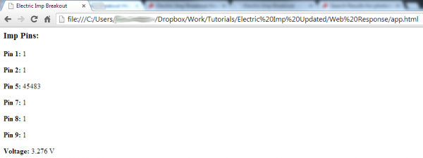
Sweet! Save and open the file with your favorite web browser. Assuming your imp is running with the new device/agent code, you should see something like this:

pinView.html view

Those 1’s, 0’s, and other numbers might be a little different on your screen. Try pressing a button. Or cover the photocell. Or mess with the imp’s pins in some other way. Are the values changing? How cool is that!

The code for this webpage is a little ugly. It uses some web “stuff” that my fragile, electrical engineer mind can barely grasp. There may be a better way to do this, but this works for us. If you find another cool way to request and use data from the imp, let us know in the discussion section!

Towards the bottom of the HTML code is a series of <span> tags, with ids like “pin1”, “pin2” etc. But they’re blank. Remember those, they’ll come in handy.

The real magic here is happening in the poll() function in the <script> area up top. This function sets up an AJAX) request to the electric imp agent. If the request succeeds, function(agentMsg) is executed. This function parses the JSON message received from the agent, and dynamically updates the data in our blank <span> tags defined below. poll() is set to be called every pollRate (defaulted to 1000) milliseconds.

Whew! Hopefully all of this stuff is easy enough to pattern-match and modify as you please. To make some other information stream to the webpage, you have to:

  1. Edit the imp Device code to send the desired data to the agent. Use the agent.send() function to do this.
  2. Edit the Agent code in two places:
    1. Read the data in from the imp in the device.on() function.
    2. In an HTTP request handler, send the data out as a JSON string.
  3. Add something in the AJAX success function to look for the correct JSON “key” and “value” combination. Then do something with that data.
  4. Add a location in the HTML body to show the data. E.g. <span id="myData"><!--Data goes here--></span>

Give it a try! It sounds like a lot of work, but most of the constructs are already there for you to quickly add new displayable data. You could print the imp’s measured RSSI, or do some math on the analog input reading to turn it into a voltage.

Resources & Going Further

Now that you know how to hook up the electric imp and its Breakout, what project will you be making with it? Will you be adding to the “Internet of Things”? Need some inspiration? Check out some of these products and projects:

  • Using the OpenSegment - The OpenSegment displays are very easy-to-use 4-digit 7-segment displays. You could easily connect these to an imp via either serial, I2C, or SPI.
  • The Uncertain 7-Cube - This project uses an Arduino to create a riff on the magic 8-ball. Swap out that Arduino with an imp, and make the Uncertain 7-Cube post to twitter or something!

If you’re looking to interface an electric imp with an Arduino, check out the Electric Imp Shield. We’ve also written a tutorial on communicating via serial between the imp and Arduino.

Resources

The folks at electric imp have loads of great resources on their wiki. Among the many links on that page, these ones stand out for being extra helpful:

  • electric imp API Reference - Here you’ll find all of the imp-specific functions.
  • electric imp Developer Forums - There’s a wealth of knowledge in the imp community. If you’ve got a question, search for an answer here, or start a new topic.
  • Imp Card Spec Sheet - A good datasheet for the imp. You’ll find electrical characteristics here, along with other useful info.

If you’re still left with imp-related questions, try consulting their forums.


learn.sparkfun.com |CC BY-SA 3.0 | SparkFun Electronics | Boulder, Colorado


Quick Illuminated Boxes

$
0
0

Quick Illuminated Boxes a learn.sparkfun.com tutorial

Arts and Crafts

I’ve got a cookie exchange to go to this holiday season, and I spent a little bit of time mulling over a way to add electronics to my box without breaking the bank. I settled on a quick and dirty throwie hack, and I thought I’d share. I used this trick for cookie boxes, but it would also make beautiful wedding favor boxes, gift boxes, or even a safe substitute for tealight walkway lights!

finished illuminated box

I bought plain favor boxes, but I’ve seen laser cut ones that would look beautiful illuminated from within!

You’ll need boxes or bags, as well as tape and a hobby knife. The wishlist below is for the parts I used to make 10 boxes. You can modify the numbers to suit your purpose, you need one of each part per box. You can also use any LED color you like!

Make your Boxes

I started with plain white favor boxes and painted a design on each one while they were still disassembled. Do whatever works stylistically for you – you can skip this step if you want to cut in the design, or are using precut boxes.

painted boxes

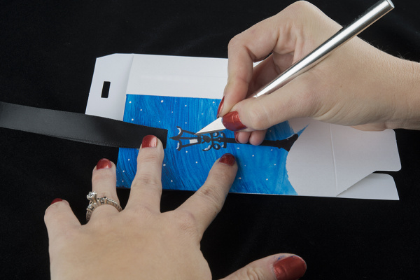
Next, use your craft knife cut a hole (or holes) where you want the light to shine through the brightest. Unless you get a black or very thick box, the whole thing will glow softly in the dark, but you’ll get a nice bright light wherever you put the hole(s). Make sure you put a piece of cardboard in the box before you cut, unless you want to cut straight through both sides.

cutting a hole in the box

Adding A Light

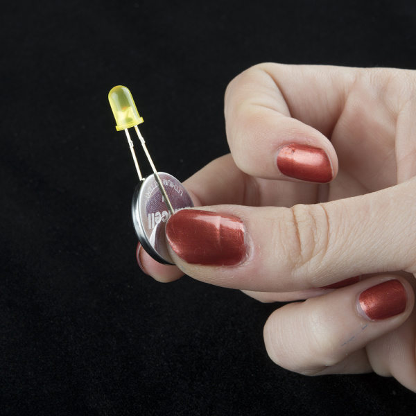
To illuminate the boxes, we’re going to use something commonly called a ‘throwie’. To make one, slide an LED onto a battery so that the two legs straddle it. The LED is polarized. Make sure you attach it to the battery with the correct orientation. The long leg should be on the positive (+) side of the battery, the side with writing stamped onto it, and the short leg should be on the negative (-), textured side. Don’t worry if you put it on backwards the first time.

holding led on battery

Wrap a piece of tape around the legs and the battery to secure it in place.

taped throwie

Tape the throwie inside your box, and the light will shine through the holes, illuminating your design and making the box look absolutely magical!

illuminated box

The box is meant to be disposable, as favor boxes generally are, so eventually the battery will die. Before that happens, though, you’ll get days of light out of it! I recommend rigging these up the day of your event. They’ll shine their brightest, and the recipients will have a lovely glow to remember you by for days after you give them their boxes!


learn.sparkfun.com |CC BY-SA 3.0 | SparkFun Electronics | Boulder, Colorado

MPR121 Hookup Guide

$
0
0

MPR121 Hookup Guide a learn.sparkfun.com tutorial

MPR121 Overview

If you are interested in adding the ‘magic’ of touch to control your electronics project, a capacitive touch sensor might be the way to go. This hookup guide will show you how to use the MPR121QR2 sensor.

The MPR121QR2 is a capacitive touch sensor controller that makes it very easy to integrate capacitive touch sensing into your project. It communicates via I2C, and works by measuring the capacitance of twelve electrode points. When an object comes close to the electrode connector, the measured capacitance changes. This signals the MPR121 that something has touched a ‘button’. The IC is also capable of driving LEDs or basic GPIO functionality on electrode pins 4 through 11, giving you a lot of freedom for setting up your project. The sensor works from 1.6V to 3.3V. The sensor isn’t very current-hungry, drawing only around 29 µA when sampling every 16 milliseconds.

Materials

To work through this tutorial, you are going to need one of the three versions of the MPR121 sensor:

You will also want a soldering iron, some hookup wires and a microcontroller capable of I2C communication. For our examples, we will be using an Arduino Uno. You will also need some kind of material to act as a capacitive sensing surface (also known as an electrode, which is not to be confused with the character Electrode). Generally, aluminum foil works well. However, you could also use coins, conductive paint, or copper tape.

Suggested Reading

The MPR121 is very easy to get started using, especially with the example code. However, if you haven’t worked with Arduino previously or aren’t familiar with I2C communication, you should check out the tutorials below.

Capacitive Touch Sensor Breakout Board

The breakout board is the most versatile option of the three MPR121 products. You can wire it up to any kind of electrode you want, and, as it is a simple breakout board, does not have a particular microcontroller footprint it favors.

MPR121 Breakout

The breakout board has 4 pins that need to be connected to your microcontroller at a minimum to get communication going: the power lines and the I2C lines. However, for our example, we are going to be also connecting the IRQ pin to more easily detect a change on one of the electrodes.

Connections

MPR121 Breakout → Arduino Uno

  • 3.3V → 3.3V
  • SCL → A5
  • SDA → A4
  • GND → GND
  • IRQ → D2

You will also want to connect the Electrode/LED pins to your electrode material you selected previously. You will want to make sure you have a good, solid connection between your material and your board, so make sure you thoroughly solder your connections.

Check out the Fritzing diagram below for how your connections should look. The yellow squares represent whatever material you decide to use for your electrodes.

Breakout Board Hookup

Communicating with the Breakout Board

To communicate with your breakout board, you will need the Arduino sketch available as a zip file here. Alternatively, you can also find the most up-to-date firmware for working with the breakout board available on GitHub. Let’s take a look and see exactly what the code is doing.

language:c
    #include "mpr121.h"
    #include <Wire.h>

    int irqpin = 2;  // Digital 2
    boolean touchStates[12]; //to keep track of the previous touch states

In this first section of the code, the MPR121 library and the Wire library are initialized. The Wire library makes I2C communication easy to use on the Arduino. The sketch also defines digital pin 2 as the IRQ pin connection, and creates 12 instances of the boolean variable touchStates.

For the second section of the code, we define the irqpin as an INPUT, telling the Arduino to monitor the digital signal coming in over that pin. Serial communication is also started at 9600 bps, s well as the Wire and mpr121 libraries.

language:c
    void setup(){
        pinMode(irqpin, INPUT);
        digitalWrite(irqpin, HIGH); //enable pullup resistor

        Serial.begin(9600);
        Wire.begin();

        mpr121_setup();
    }

The main loop of the code is incredibly simple, as it only calls a single function.

language:c
    void loop(){
        readTouchInputs();
    }

The function is actually described in the next section of the code. The Arduino requests the electrode states from the sensor in the first section, and the least significant bits and most significant bits are defined for the sensor.

language:c
void readTouchInputs(){
  if(!checkInterrupt()){

    //read the touch state from the MPR121
    Wire.requestFrom(0x5A,2);

    byte LSB = Wire.read();
    byte MSB = Wire.read();

    uint16_t touched = ((MSB << 8) | LSB); //16bits that make up the touch states


    for (int i=0; i < 12; i++){  // Check what electrodes were pressed
      if(touched & (1<<i)){

        if(touchStates[i] == 0){
          //pin i was just touched
          Serial.print("pin ");
          Serial.print(i);
          Serial.println(" was just touched");

        }else if(touchStates[i] == 1){
          //pin i is still being touched
        }

        touchStates[i] = 1;
      }else{
        if(touchStates[i] == 1){
          Serial.print("pin ");
          Serial.print(i);
          Serial.println(" is no longer being touched");

          //pin i is no longer being touched
       }

        touchStates[i] = 0;
      }

    }

  }
}

The Arduino scans each electrode and prints out a message over serial if an electrode is triggered as being touched. The Arduino will then print out a message as soon as the electrode is no longer being touched.

The last major section of the code defines the threshold values for each electrode. Each electrode must have a touch threshold and a release threshold for the Arduino to compare the current state of the electrode.

language:c
void mpr121_setup(void){

  set_register(0x5A, ELE_CFG, 0x00);

  // Section A - Controls filtering when data is > baseline.
  set_register(0x5A, MHD_R, 0x01);
  set_register(0x5A, NHD_R, 0x01);
  set_register(0x5A, NCL_R, 0x00);
  set_register(0x5A, FDL_R, 0x00);

  // Section B - Controls filtering when data is < baseline.
  set_register(0x5A, MHD_F, 0x01);
  set_register(0x5A, NHD_F, 0x01);
  set_register(0x5A, NCL_F, 0xFF);
  set_register(0x5A, FDL_F, 0x02);

  // Section C - Sets touch and release thresholds for each electrode
  set_register(0x5A, ELE0_T, TOU_THRESH);
  set_register(0x5A, ELE0_R, REL_THRESH);

  set_register(0x5A, ELE1_T, TOU_THRESH);
  set_register(0x5A, ELE1_R, REL_THRESH);

  set_register(0x5A, ELE2_T, TOU_THRESH);
  set_register(0x5A, ELE2_R, REL_THRESH);

  set_register(0x5A, ELE3_T, TOU_THRESH);
  set_register(0x5A, ELE3_R, REL_THRESH);

  set_register(0x5A, ELE4_T, TOU_THRESH);
  set_register(0x5A, ELE4_R, REL_THRESH);

  set_register(0x5A, ELE5_T, TOU_THRESH);
  set_register(0x5A, ELE5_R, REL_THRESH);

  set_register(0x5A, ELE6_T, TOU_THRESH);
  set_register(0x5A, ELE6_R, REL_THRESH);

  set_register(0x5A, ELE7_T, TOU_THRESH);
  set_register(0x5A, ELE7_R, REL_THRESH);

  set_register(0x5A, ELE8_T, TOU_THRESH);
  set_register(0x5A, ELE8_R, REL_THRESH);

  set_register(0x5A, ELE9_T, TOU_THRESH);
  set_register(0x5A, ELE9_R, REL_THRESH);

  set_register(0x5A, ELE10_T, TOU_THRESH);
  set_register(0x5A, ELE10_R, REL_THRESH);

  set_register(0x5A, ELE11_T, TOU_THRESH);
  set_register(0x5A, ELE11_R, REL_THRESH);

  // Section D
  // Set the Filter Configuration
  // Set ESI2
  set_register(0x5A, FIL_CFG, 0x04);

  // Section E
  // Electrode Configuration
  // Set ELE_CFG to 0x00 to return to standby mode
  set_register(0x5A, ELE_CFG, 0x0C);  // Enables all 12 Electrodes


  // Section F
  // Enable Auto Config and auto Reconfig
  /*set_register(0x5A, ATO_CFG0, 0x0B);
  set_register(0x5A, ATO_CFGU, 0xC9);  // USL = (Vdd-0.7)/vdd*256 = 0xC9 @3.3V   set_register(0x5A, ATO_CFGL, 0x82);  // LSL = 0.65*USL = 0x82 @3.3V
  set_register(0x5A, ATO_CFGT, 0xB5);*/  // Target = 0.9*USL = 0xB5 @3.3V

  set_register(0x5A, ELE_CFG, 0x0C);

}

It looks like a lot of code, but it simply repeating the procedure of setting the threshold values for each electrode pin.

The last two functions in the example sketch simply check the status of the irqpin to determine if the IC is signaling that an electrode has been touched. The very last function set_register simply runs the Arduino through the standard steps in the Wire library to write the registers to the IC.

language:c
boolean checkInterrupt(void){
  return digitalRead(irqpin);
}


void set_register(int address, unsigned char r, unsigned char v){
    Wire.beginTransmission(address);
    Wire.write(r);
    Wire.write(v);
    Wire.endTransmission();
}

Now that you have a basic understanding of the code, let’s start reading the data. Open up the sketch from the file you downloaded earlier, and upload it to your Arduino. Once it is uploaded, open the Serial monitor in the Arduino IDE. You should start seeing the Arduino print out sentences if you press any electrodes or release any electrodes.

Touch Shield

The Touch Shield is an Arduino R3 compatible shield that enables capacitive touch capabilities for your project using the MPR121 IC. The shield itself has 9 touch pads on it (conveniently numbered 1-9 in a 3x3 grid), and has headers for 3 additional electrode connections.

Touch Shield

The shield connects directly to the 3.3V pin on the Arduino. There is no on-board voltage regulation on the VCC line, so keep that in mind if you intend to use this with a 5V Arduino Pro board. However, there is an onboard logic level converter to step down 5V levels to the 3.3V for the sensor’s I2C lines.

This shield is designed to interface with an Arduino Uno R3. You can use other microcontrollers as well with the same footprint, such as the Arduino Mega. You will need access to the I2C pins, SDA and SCL. Other than that, you will need access to the 3.3V and GND pins and to digital pin 2. This connects to the INT pin on the MPR121 sensor.

We generally use stackable headers for attaching shields to Arduino boards, but you can use standard male headers if you prefer. The R3 Stackable Header Kit is the easiest option to use if you are planning on stackable headers. For detailed instructions on how to assemble your shield, have a look at our Shield Tutorial.

The shield also has 3 pins labeled ELE9, ELE10, and ELE11. These correspond to electrodes 9,10, and 11 on the MPR121 chip. You can solder additional buttons or connections on to these pins at this time if you want more than the 9 buttons already available on the shield. However, you don’t have to do this to get the shield to function. It’s up to you!

Check out the Fritzing diagram below to see how your shield should look if you have added buttons on to your shield on pins ELE9, ELE10, and ELE11.

Touch Shield Hookup

Note: The yellow squares represent whatever material you’ve chosen to use as your electrode.

Once you’ve got your shield all hooked up, let’s start pulling data from the shield!

Communicating with the Shield

Once you’ve got your shield assembled, it’s time to start talking to it! You can download the example code here, or find the most up-to-date version in the GitHub repository.

Open up the Touch_Sensor_Shield_Example.ino file. The other files set the register definitions for the MPR121 chip, so you shouldn’t need to mess with these at all.

language:c
    // Match key inputs with electrode numbers
    #define ONE 8
    #define TWO 5
    #define THREE 2
    #define FOUR 7
    #define FIVE 4
    #define SIX 1
    #define SEVEN 6
    #define EIGHT 3
    #define NINE 0

    //extras (not connected to button)
    #define ELE9 9
    #define ELE10 10
    #define ELE11 11

    //interupt pin
    int irqPin = 2;  // D2

First thing the code shows is the pin definitions. This is laying out the keypad functionality (ONE, TWO, etc.) and defining which electrode pin corresponds to each number. As the comment states, electrode pins 9, 10 and 11 are not currently connected to anything, but if you did solder on additional buttons to those pins on the shield, you can change this.

The interrupt pin is also defined as D2. This can’t be modified without some hardware hacking on the shield, so keep that in mind if you are interfacing additional hardware into your set up.

language:c
    void setup()
    {
      //make sure the interrupt pin is an input and pulled high
      pinMode(irqPin, INPUT);
      digitalWrite(irqPin, HIGH);

      //configure serial out
      Serial.begin(9600);

      // initalize I2C bus. Wiring lib not used.
      i2cInit();

      // initialize mpr121
      mpr121QuickConfig();

      // Create and interrupt to trigger when a button
      // is hit, the IRQ pin goes low, and the function getNumber is run.
      attachInterrupt(0,getNumber,LOW);

      // prints 'Ready...' when you can start hitting numbers
      Serial.println("Ready...");
    }

The setup loop starts by setting the interrupt pin as an input and pulling it high. The serial bus is started at 9600 bps. Next, the code initializes the I2C communication lines without using the Wiring library.

The MPR121 chip is then configured with the proper sensitivity settings on the electrodes. The final step in the setup loop creates an interrupt in the code that will trigger when any of the buttons are hit.

language:c

    void loop()
{
  //You can put additional code here. The interrupt will run in the backgound.
}

The loop function is actually empty currently, as the button presses use the interrupt we created in the setup loop. If you did have additional hardware you wanted to incorporate into your project, the code for it can live in this loop.

The last two functions in the example code tell the Arduino to check the electrode states for a button press and what to print out when a button press is detected.

language:c
void getNumber()
{
  int touchNumber = 0;
  uint16_t touchstatus;
  char digits;

  touchstatus = getTouchStatus();

  for (int j=0; j<12; j++)  // Check how many electrodes were pressed
  {
    if ((touchstatus & (1<<j)))
      touchNumber++;
  }

  if (touchNumber == 1)
  {
    if (touchstatus & (1<<SEVEN))
    {
      digits = '7';
    }
    else if (touchstatus & (1<<FOUR))
    {
      digits = '4';
    }
    else if (touchstatus & (1<<ONE))
    {
      digits = '1';
    }
    else if (touchstatus & (1<<EIGHT))
    {
      digits = '8';
    }
    else if (touchstatus & (1<<FIVE))
    {
      digits = '5';
    }
    else if (touchstatus & (1<<TWO))
    {
      digits = '2';
    }
    else if (touchstatus & (1<<NINE))
    {
      digits = '9';
    }
    else if (touchstatus & (1<<SIX))
    {
      digits = '6';
    }
    else if (touchstatus & (1<<THREE))
    {
      digits = '3';
    }
    Serial.println(digits);
  }
  //do nothing if more than one button is pressed, or if all are released
  else if (touchNumber == 0)
    ;
  else
    ;
}

The function getTouchStatus() actually returns at 16-bit value which gives the status of each button. The status of 1 indicates that an electrode is being activated.

language: c
    int getTouchStatus()
{
  int touch;

  touch = mpr121Read(0x01) << 8;
  touch |= mpr121Read(0x00);

  return touch;
}

Now that you have basic communication up and running with your shield, you can start integrating this into projects. If you haven’t yet connected anything to electrodes 9, 10 and 11, consider adding in additional buttons here. You will also need to update the code. You’ll want to add the following block of code into the example sketch right before Serial.println(digits);. You can change the digits values to have the buttons output different values instead of “A”, “B”, or “C”.

language:c
    else if (touchstatus & (1 << ELE9))
{
  digits = 'A';
}
else if (touchstatus & (1 << ELE10))
{
  digits = 'B';
}
else if (touchstatus & (1 << ELE11))
{
  digits = 'C';
}

Capacitive Touch Keypad

The Capacitive Touch Keypad is very similar to the MPR121 breakout board, but instead of having to attach your own electrodes, this board comes with a 12-pin keypad built-in.

keypad

The keypad has 5 lines that need to be connected to your microcontroller, including the power lines, the IRQ line and the I2C lines.

Connections

MPR121 Keypad → Arduino Uno

  • 3.3V → 3.3V
  • SCL → A5
  • SDA → A4
  • GND → GND
  • IRQ → D2

Check out the Fritzing diagram below to verify your connections.

MPR121 Keypad Hookup

This diagram shows the bottom side of the keypad, in order to show you the location of the I2C address jumper. In this diagram, the jumper is set to 0, but if you need to have 2 keypads on the same I2C bus, you can change one of them to be set to 1.

Now that you’ve got your keypad hooked up properly, let’s get communicating with it!

Communicating with the Keypad

In order to communicate with your keypad, you’ll want to download the example sketch available here. Alternatively, you can check for the most up-to-date firmware available in the GitHub repository.

This sketch is designed to allow the keypad to function as a phone keypad. Check out the pin mapping below to see how the numbered pads will print over the Serial terminal.

Actual Keypad → Phone Keypad Printout

  • 3 → 1
  • 7 → 2
  • 11 → 3
  • 2 → 4
  • 6 → 5
  • 10 → 6
  • 1 → 7
  • 5 → 8
  • 9 → 9
  • 0 → *
  • 4 → 0
  • 8 → #

This is defined in the first section of the code, shown below. The I2C address is also defined, along with setting digital pin 2 to be assigned as the IRQ pin connection point.

language:c
#include "mpr121.h"
#include "i2c.h"

#define MPR121_R 0xB5    // ADD pin is grounded
#define MPR121_W 0xB4   // So address is 0x5A

#define PHONE_DIGITS 10  // 10 digits in a phone number

// Match key inputs with electrode numbers
#define STAR 0
#define SEVEN 1
#define FOUR 2
#define ONE 3
#define ZERO 4
#define EIGHT 5
#define FIVE 6
#define TWO 7
#define POUND 8
#define NINE 9
#define SIX 10
#define THREE 11

int irqpin = 2;  // D2

uint16_t touchstatus;
char phoneNumber[PHONE_DIGITS];

The second section of the code is the basic initialization of the serial communication port at 9600 bps, as well as setting the IRQ pin as an input on the Arduino. It also starts the configuraton of the MPR121 IC.

language:c
void setup()
{
  pinMode(irqpin, INPUT);
  digitalWrite(irqpin, HIGH);

  Serial.begin(9600);
  DDRC |= 0b00010011;
  PORTC = 0b00110000;  // Pull-ups on I2C Bus
  i2cInit();

  delay(100);
  mpr121QuickConfig();
}

The main loop in the code simply scans the MPR121 electrodes and looks for a phone number to be entered on the keypad. This is the function getPhoneNumber(). The code then prints out the phone number dialed over the serial monitor.

language:c
void loop()
{
  getPhoneNumber();

  Serial.print("\nDialing... ");
  for (int i=0; i<PHONE_DIGITS; i++)
    Serial.print(phoneNumber[i]);

  while(1)
    ;
}

As you can see in the function loop for getPhoneNumber(), the Arduino checks the touchstatus register for each electrode and prints out the assigned value for any electrodes that are registering a touch. It also includes an error if multiple buttons are pressed simultaneously, printing over the serial monitor to tell the user to touch only one button.

language:c
void getPhoneNumber()
{
  int i = 0;
  int touchNumber;

  Serial.println("Please Enter a phone number...");

  while(i<PHONE_DIGITS)
  {
    while(checkInterrupt())
      ;
    touchNumber = 0;

    touchstatus = mpr121Read(0x01) << 8;
    touchstatus |= mpr121Read(0x00);

    for (int j=0; j<12; j++)  // Check how many electrodes were pressed
    {
      if ((touchstatus & (1<<j)))
        touchNumber++;
    }

    if (touchNumber == 1)
    {
      if (touchstatus & (1<<STAR))
        phoneNumber[i] = '*';
      else if (touchstatus & (1<<SEVEN))
        phoneNumber[i] = '7';
      else if (touchstatus & (1<<FOUR))
        phoneNumber[i] = '4';
      else if (touchstatus & (1<<ONE))
        phoneNumber[i] = '1';
      else if (touchstatus & (1<<ZERO))
        phoneNumber[i] = '0';
      else if (touchstatus & (1<<EIGHT))
        phoneNumber[i] = '8';
      else if (touchstatus & (1<<FIVE))
        phoneNumber[i] = '5';
      else if (touchstatus & (1<<TWO))
        phoneNumber[i] = '2';
      else if (touchstatus & (1<<POUND))
        phoneNumber[i] = '#';
      else if (touchstatus & (1<<NINE))
        phoneNumber[i] = '9';
      else if (touchstatus & (1<<SIX))
        phoneNumber[i] = '6';
      else if (touchstatus & (1<<THREE))
        phoneNumber[i] = '3';

      Serial.print(phoneNumber[i]);
      i++;
    }
    else if (touchNumber == 0)
      ;
    else
      Serial.println("Only touch ONE button!");
  }
}

The next section of the code simply steps through the I2C communication to read data from the MPR121 IC.

language:c
byte mpr121Read(uint8_t address)
{
  byte data;

  i2cSendStart();
  i2cWaitForComplete();

  i2cSendByte(MPR121_W);    // write 0xB4
  i2cWaitForComplete();

  i2cSendByte(address); // write register address
  i2cWaitForComplete();

  i2cSendStart();

  i2cSendByte(MPR121_R);    // write 0xB5
  i2cWaitForComplete();
  i2cReceiveByte(TRUE);
  i2cWaitForComplete();

  data = i2cGetReceivedByte();  // Get MSB result
  i2cWaitForComplete();
  i2cSendStop();

  cbi(TWCR, TWEN);  // Disable TWI
  sbi(TWCR, TWEN);  // Enable TWI

  return data;
}

The function mpr121Write() is then defined, which again, steps through the I2C process of writing commands to the MPR121 sensor.

language:c
void mpr121Write(unsigned char address, unsigned char data)
{
  i2cSendStart();
  i2cWaitForComplete();

  i2cSendByte(MPR121_W);// write 0xB4
  i2cWaitForComplete();

  i2cSendByte(address);    // write register address
  i2cWaitForComplete();

  i2cSendByte(data);
  i2cWaitForComplete();

  i2cSendStop();
}

The mpr121QuickConfig() function is then defined. In this function, all 12 of the electrodes are enabled, and the touch and release thresholds for all of the sensors are set. The filtering registers are also configured.

language:c
void mpr121QuickConfig(void)
{
  // Section A
  // This group controls filtering when data is > baseline.
  mpr121Write(MHD_R, 0x01);
  mpr121Write(NHD_R, 0x01);
  mpr121Write(NCL_R, 0x00);
  mpr121Write(FDL_R, 0x00);

  // Section B
  // This group controls filtering when data is < baseline.
  mpr121Write(MHD_F, 0x01);
  mpr121Write(NHD_F, 0x01);
  mpr121Write(NCL_F, 0xFF);
  mpr121Write(FDL_F, 0x02);

  // Section C
  // This group sets touch and release thresholds for each electrode
  mpr121Write(ELE0_T, TOU_THRESH);
  mpr121Write(ELE0_R, REL_THRESH);
  mpr121Write(ELE1_T, TOU_THRESH);
  mpr121Write(ELE1_R, REL_THRESH);
  mpr121Write(ELE2_T, TOU_THRESH);
  mpr121Write(ELE2_R, REL_THRESH);
  mpr121Write(ELE3_T, TOU_THRESH);
  mpr121Write(ELE3_R, REL_THRESH);
  mpr121Write(ELE4_T, TOU_THRESH);
  mpr121Write(ELE4_R, REL_THRESH);
  mpr121Write(ELE5_T, TOU_THRESH);
  mpr121Write(ELE5_R, REL_THRESH);
  mpr121Write(ELE6_T, TOU_THRESH);
  mpr121Write(ELE6_R, REL_THRESH);
  mpr121Write(ELE7_T, TOU_THRESH);
  mpr121Write(ELE7_R, REL_THRESH);
  mpr121Write(ELE8_T, TOU_THRESH);
  mpr121Write(ELE8_R, REL_THRESH);
  mpr121Write(ELE9_T, TOU_THRESH);
  mpr121Write(ELE9_R, REL_THRESH);
  mpr121Write(ELE10_T, TOU_THRESH);
  mpr121Write(ELE10_R, REL_THRESH);
  mpr121Write(ELE11_T, TOU_THRESH);
  mpr121Write(ELE11_R, REL_THRESH);

  // Section D
  // Set the Filter Configuration
  // Set ESI2
  mpr121Write(FIL_CFG, 0x04);

  // Section E
  // Electrode Configuration
  // Enable 6 Electrodes and set to run mode
  // Set ELE_CFG to 0x00 to return to standby mode
  mpr121Write(ELE_CFG, 0x0C);    // Enables all 12 Electrodes
  //mpr121Write(ELE_CFG, 0x06);     // Enable first 6 electrodes

  // Section F
  // Enable Auto Config and auto Reconfig
  /*mpr121Write(ATO_CFG0, 0x0B);
  mpr121Write(ATO_CFGU, 0xC9);  // USL = (Vdd-0.7)/vdd*256 = 0xC9 @3.3V   mpr121Write(ATO_CFGL, 0x82);  // LSL = 0.65*USL = 0x82 @3.3V
  mpr121Write(ATO_CFGT, 0xB5);*/    // Target = 0.9*USL = 0xB5 @3.3V
}

The final section of the sketch simply reads the IRQ pin for an indication that an electrode has been pressed. It then returns either a 1 or 0 as the value for checkInterrupt() variable.

language:c
byte checkInterrupt(void)
{
  if(digitalRead(irqpin))
    return 1;

  return 0;
}

Now that you know how the keypad works and communicates with the Arduino, you can start customizing your project and going further.

Resources and Going Further

Now that you’ve figured out how to use the various versions of the MPR121 IC, what kind of cool projects can you come up with? If you have any questions still, check out the additional resources below, or feel free to leave a comment on the tutorial.

Resources

Other I2C Projects and Products

All of these tutorials have I2C communication. They can also both be used in conjunction with this sensor to act as a display for the button triggers or to monitor the temperature as well.


learn.sparkfun.com |CC BY-SA 3.0 | SparkFun Electronics | Boulder, Colorado

Copernicus II Hookup Guide

$
0
0

Copernicus II Hookup Guide a learn.sparkfun.com tutorial

Copernicus II Overview

The Copernicus II GPS Module is a 12-channel receiver from Trimble. It has a small form factor, making it a great device for applications requiring precise GPS control. The DIP module board allows you to easily embed this into your projects by providing an easy to connect to interface.

The module supports NMEA, TSIP and TAIP protocols at 1 Hz. The board also is designed to interface with an SMA antenna.

Copernicus II DIP Module

The Copernicus II DIP Module

The module runs at 3.3V and consumes around 40mA at 3.0V. For the TSIP protocol, the module’s default baud rate is 38400 bps, while it defaults to 4800 bps for the NMEA protocol. These settings are configurable. The module is permanently set to 8 data bits, no parity, 1 stop bits and no flow control.

Suggested Reading

If you haven’t worked with GPS before, or are unfamiliar with serial communication, you may want to read the following tutorials before continuing on with this module.

Hardware Hookup

To get started communicating with the Copernicus II, you will need to connect four pins on the module: VCC, GND, TX-B, and RX-B.

For our example, we will be connecting the module to a terminal window on the computer using an 3.3V FTDI Basic Board, and will be using the GPS Antenna Embedded SMA.

Connections:

Copernicus II → FTDI Basic

  • VCC → 3.3V
  • GND → GND
  • TX-B → RXI
  • RX-B → TXO

Take a look at the Fritzing diagram below showing the connections between the Copernicus II and the FTDI Basic.

Copernicus_II Hookup

Talking to the Module

Once you have your boards connected, open up your favorite serial terminal program and connect to the appropriate COM port for your FTDI Basic. The connection settings should be 4800 bps, 8 data bits, no parity, 1 stop bit, and no flow control.

If your module is hooked up properly and has a lock, you should see a scrolling output like this.

Copernicus Module Output

Copernicus II output in CoolTerm terminal window

As you can see in the GPGGA output, the module is reading the position to be 4003.89135 N and 10512.58816 W, which happens to be SparkFun’s headquarters. The module is also currently only seeing 7 satellites. The lack of additional data is due to testing this inside a large building like SparkFun, so you should actually be getting more data from your module if testing near a window or outside with a clear view.

Talking to a Microcontroller

If you’re looking to add GPS to your Arduino project using the Copernicus, we suggest you look into the Tiny GPS library. This library is great for parsing out the data that you want to use in your project such as time, altitude, position, etc. There are plenty of resources involving this library around the web. A quick search should yield plenty of examples. If you need a refresher on how to install an Arduino library, instructions can be found here.

Resources and Going Further

Now that you’ve gotten your module hooked up and can collect gps data from it, it’s time to start integrating the module into your projects. Think about adding in gps navigation to an autonomous robot or creating a data logger for your car to track gas usage in different areas. Let us know what kind of cool projects you come up with, and leave us any feedback you might have on the tutorial. Check the files below for additional resources.

Resources


learn.sparkfun.com |CC BY-SA 3.0 | SparkFun Electronics | Boulder, Colorado

Setting up Raspbian (and DOOM!)

$
0
0

Setting up Raspbian (and DOOM!) a learn.sparkfun.com tutorial

Introduction

The Raspberry Pi is a cross between a typical embedded system – like an Arduino– and a desktop computer. The Pi packs a 700MHz ARM11 Core with 512MB of RAM, HDMI and audio outputs, 2 USB ports, an Ethernet jack, and an SD socket with support for up to a 32GB SD card. In the eyes of some, it’s one of the more powerful, cost-effective embedded boards to hit the market. To others, it’s one of the most compact, bare-bones personal computers ever to grace the electronics world with it’s presence. In either case, it’s here to blur the line between the world of embedded electronics and personal computing.

Pi ISO shot

The Raspberry Pi is a great platform on which to learn Linux and programming. It’s also a powerful solution for many “Internet-of-Things” projects out there, because it’s so easy to get connected to the Internet. It can run Python scripts, or even compile programs written in C. It’s a full-blown computer!

And, of course, it can be used to play games.

Doom on the Pi

Chocolate Doom running on the Pi.

Covered in This Tutorial

In this tutorial, we’ll show you how to quickly get up-and-running with the Raspberry Pi. We’ll set the Pi up with the most popular, community-driven Linux distribution available: Raspbian. Next, we’ll show you how to set up Raspbian, and access some of the features included with it.

Finally, and most importantly, we’ll show you how to set up and run Chocolate Doom, a Doom source port that runs beautifully on the little Pi. Mmmm chocolate pie.

Required Materials

To follow along with this tutorial, you’ll need the following materials:

List of materials

  • Raspberry Pi Model B or Model A (has less RAM and no Ethernet)
  • A 5V power supply with a micro USB termination. The supply should be able to source at least 700mA. Most phone chargers (with micro USB cables) should work.
  • An SD Card no smaller than 4GB, and no less than class 4.
  • A USB keyboard and mouse.
  • A display connected to either the HDMI or RCA composite video output.
    • If your monitor only has a VGA port, there are HDMI to VGA adapters to convert between the two. (You may need a beefier power supply if you’re using that.)
    • If your monitor only has DVI, converting from HDMI is easy with an HDMI to DVI cable.
  • An ethernet cable and a connection to an Internet-connected network. (Optional, but very useful to get software updates [and Doom].)
    • Alternatively, you can use a USB WiFi module with the Pi. Check out our Wireless on the Pi tutorial for help setting that up.
  • Headphones or speakers with a 3.5mm stereo jack termination (optional, unless, for some reason, you don’t want to hear the dying wails of former humans).

Suggested Reading

This tutorial aims to be as Raspberry Pi beginnger-friendly as possible. No previous knowledge of electronics is required. Feel free to jump right in on the next page. If you want to learn a little bit about what’s going on behind the scenes, here are some beginner tutorials we recommend reading:

Prepare an SD Card

Before you can start installing Raspbian, you’ll have to get the installer set up on an SD card. Follow the steps below to prepare your SD card by formatting it, and then installing the NOOBS software.

Regardless of which operating system you’re using, begin by inserting your SD card into your computer. Then, you’ll need to begin by formatting the card. Follow along with the section below that matches your OS.

Format the Card

Windows

  1. DownloadSDFormatter for Windows. Unzip it, and run Setup.exe. Follow along with the InstallShield Wizard to install SDFormatter.
  2. Open SDFormatter.
  3. Click Option and set FORMAT SIZE ADJUSTMENT to ON.


  4. Select your card from the Drive dropdown menu (if it wasn’t selected automatically). Check and double-check that the drive letter is correct.
  5. Click Format, then click OK a couple times. You should get a Drive Format complete! pop up shortly.

Mac OS X

  1. DownloadSDFormatter for Mac. Open the the downloaded file, and follow the Installer directions to install.
  2. Open SDFormatter (it should be in your Applications folder).
  3. Select Overwrite Format as the format option.


  4. Select your card from the top dropdown menu (if it wasn’t selected automatically). Make sure it’s correct!
  5. Click Format, and watch the progress bar slowly crawl across the bottom of the window. A Card Format complete ! message should appear once successful.

Download NOOBS

Raspberry Pi’s New Out of Box Software (NOOBS) is recommended for first time Pi users (and even advanced ones). It includes a variety of useful operating system images (including Raspbian), and really simplifies the process of installing them.

Head over to the Raspbery Pi downloads page, and download the most recent NOOBS (offline install) image (NOOBS_v1_3_2.zip as of writing this). It should be a 1-ish GB ZIP folder.

Once the download has finished, extract the ZIP folder and place the contents at the top level of your SD card. Once unzipped, the directory structure should look a little something like this:

SD card directory structure

Dang! That is one prepared SD card. Time to set up the Pi.

Prepare the Pi

This page is all about connecting peripherals to your Pi in preparation for installing Raspbian. So preheat your oven and let’s get cooking.

Connect Display

There are two potential places to connect a display on the Pi: either HDMI or component video.

HDMI connected to Pi

If your monitor has neither of those inputs, a VGA-to-HDMI adapter or HDMI to DVI cable might be what you need.

HDMI does carry audio, if your display can support that. Otherwise you can use the 3.5mm jack on the other side.

Connect USB Peripherals

Next up, connect your mouse and keyboard. As long as you don’t plan to use any other USB peripherals (flash drives, WiFi cards, etc.) you can use both USB ports on the Pi. Otherwise, you may want to look into adding a USB hub.

USB connected to Pi

Some of these peripherals can use a lot of power (especially optical and wireless mice). If you notice issues with the mouse or keyboard, you may need to use them with a powered USB hub.

Insert SD Card

Insert your prepared SD card into the Pi. The SD socket is on the bottom side of the board. When inserting your card, make sure the gold contacts are facing up toward the board.

SD inserted into Pi

(Optional, Recommended) Connect Ethernet

In order to download updates and other software for your Pi, it’s recommended that you connect it to an Internet-connected network via Ethernet. The Ethernet jack sits right next to the pair of USB sockets.

Connect Power

Power time! Plug your micro-B USB cable into your wall adapter, then plug the other end into your Pi’s small, micro-B USB port.

Power connected to Pi

The Pi-quad-topus is complete. Time to power it up!

The Pi doesn’t have a power switch, so make sure everything else is plugged in before connecting power. As soon as power is applied to the Pi, it’ll look at the contents of the SD card and begin to boot up.


Quick! As the Pi begins to boot for the first time, head over to the next page for further directions.

Install Raspbian

As your Pi begins to boot for the first time, you should be presented with the image installation screen. If so, skip down to the Image Installation Selection section. Otherwise, time for some quick troubleshooting:

Blank, Black Display on First Boot?

If you’re turning on your Pi for the first time, and don’t see anything on the screen, don’t fret! As long as your monitor isn’t complaining about “No Signal”, the Pi probably is working.

First, try pressing either 1, 2, 3, or 4 on your keyboard depending on which display mode you need:

  1. HDMI– Regular HDMI mode.
  2. HDMI safe– Try this if you’re using HDMI, but option 1 doesn’t work.
  3. Composite PAL– Composite cable, PAL signal out.
  4. Composite NTSC– Composite cable, NTSC signal out.

After selecting the correct mode, your screen should continue on to the install selection screen.

Still No Luck?

If your screen is still blank, you may have to manually configure it. Try this:

  1. Unplug your Pi, take out the SD card, and plug it back into your computer.
  2. Create a new file called config.txt at the top level of your SD card.
  3. In config.txt add these lines:
    hdmi_drive=2            # HDMI/DVI mode (1=DVI, 2=HDMI)
    hdmi_group=2            # HDMI type (1=CEA, 2=DMT)
    hdmi_mode=16            # Resolution (9=800x600/60Hz, 16=1024x768/60, 28=1280x800/60)
    hdmi_force_hotplug=1    # 1=Force HDMI mode even if no HDMI montor is detected

You may need to alter some values there. These settings manually define things like HDMI mode and resolution. For more help altering the config.txt file, check out the RPiconfig page.

(These values were required for an old 15-inch monitor connected to the Pi via a VGA-to-HDMI adapter.)

Image Install Selection

The first step in NOOBS setup is selecting which images to install. We recommend selecting at least Raspbian. If you have a lot of space on your card, you can install multiple operating system images.

Use you mouse to select or de-select options (or navigate up and down with the arrow keys, and Spacebar to select).

NOOBS image selector

After selecting the image, you can modify the language setting. Then click install or press i to start the installation.

The installation procedure will take a while (30 minutes to an hour-ish). Read the handful of installation slides:

Raspbian install slides

Then go take a break to bake some pie or something.

Setup Raspbian

After NOOBS runs through the installation process the Raspberry Pi will reboot, and present you with the Raspberry Pi Software Configuration Tool (if you don’t see this, scroll down to the next section:

Raspi-config tool

  1. Expand Filesystem– Don’t worry about this. NOOBS already did it for you.
  2. Change User Password– This step is recommended! Follow the on-screen directions to set a new password for you Pi. By default the password is set to raspberry, and the user is set to pi.
  3. Enable Boot to Desktop/Scratch– Select whether to boot into desktop or simply the text console. The console mode will obviously boot faster, and you can type Startx to open the GUI. Booting to desktop may be easier for those more comfortable with Windows or Mac, though.
  4. Internationalisation Options– Here you can adjust the timezone, keyboard layout, and language of your Pi. These changes take a while to be made, so be patient.
  5. Enable Camera– If you’ve got a Raspberry Pi Camera, this is the setting for you.
  6. Add to Rastrack– If you want your Pi to be documented on Rastrack.
  7. Overclock– If really want to ride your Pi to the max, you can overclock it. This taxes the entire system, and can lead to failures. Make sure you have a beefier power supply if you overclock. We recommend at least trying the Pi at normal clock settings, before deciding to overclock it.
  8. Advanced Options– There are some fun options here, like setting the hostname or enabling/disabling SPI and SSH. For the most part, these options can be left alone, though.

Once you’ve made all of your adjustments, scroll down and over to <Finish> and allow the Pi to Reboot.

If you booted into console mode, type Startx to open the GUI. Otherwise, you’ll already be presented with the beautiful Raspberry Pi desktop.

Raspbian desktop

The default Raspbian desktop.

Booting to Blank, Black Screen?

If, after installing Raspbian, your Pi boots up only to land back on a blank, black screen, you may need to edit another config.txt. This one specific to the Raspbian install.

The key to this is entering recovery mode. When the Pi is booting, you should at least see this screen:

Raspberry Pi recovery mode wallpaper

As soon as you see that grey, recovery mode screen hold down shift to enter recovery mode. This should present you with a familiar looking window. “Raspbian” should already be selected, and it should have a greenish background to indicate it’s installed. Select your Raspbian image, and then click Edit config (e) (or press e) to open config.txt.

Config editor

Each line that begins with a # is commented out, so scroll down to the very bottom where there are a handful of non-comment lines. This is where you’ll want to modify the NOOBS Auto-generated Settings to match what you need. If you had to manually create a config.txt file in the last step, try using those same values. For example, this worked for us:

hdmi_drive=2            # HDMI/DVI mode (1=DVI, 2=HDMI)
hdmi_group=2            # HDMI type (1=CEA, 2=DMT)
hdmi_mode=16            # Resolution (9=800x600/60Hz, 16=1024x768/60, 28=1280x800/60)
hdmi_force_hotplug=1    # 1=Force HDMI mode even if no HDMI montor is detected

Check out the RPiconfig page for more help adjusting keys and values. Make sure you comment out (or replace) the keys and values that were already there.

Then hit ESC and cross your fingers as the Pi reboots. If you see a wall of scrolling text as the operating system begins to boot, that’s a good sign! If not, go back to recovery mode and try modifying config.txt some other way.

Exploring Raspbian

Raspbian comes with a variety of useful software tools. The UI should feel generally similar to Windows, OS X, and other Linux OS'es you may have used.

Annoatated desktop

You can explore the environment on your own, but here are some of our favorite included tools:

File Manager

If you’ve done any sort of file manipulation, creation, or deletion, you’ve probably encountered a file browser before. Open the File Manager by clicking the second icon from the left on the bottom taskbar.

File manager

Using the file manager to browse around the Applications folder.

You can use the File Manager to look around at what files, applications, and tools are included with Raspbian. Or you can be a little more Linux-y by using the terminal…

LXTerminal

LXTerminal is Raspbian’s default terminal program. If thinking of “Linux” conjures images of hackers typing furiously into a text-filled black-and-white terminal, LXTerminal is the actualization of that.

LXTerminal

If you’ve never used Linux, or are unfamiliar with the command line interface (CLI), there are plenty of resources to help get you started. Begin with navigating around using cd, list some directory contents with ls, read some command manuals with man, and you’ll be a command line ninja in no time.

Midori

Midori is the default web browser bundled with Raspbian. Midori aims to be both fast and lightweight, but it can still handle a lot of modern web pages.

Midori

Browsing SFE from Midori.

With Midori you have access to tabs, bookmarks, search bars, and other utilities you may be accustomed to with using other web browsers. No Flash, though, so no Youtube'ing.

Text Editors: Nano & Leafpad

Both of these text editors can be used to modify text files, which is necssary to configure many applications. The difference between the two is the GUI. Leafpad is a few-frills, graphical text editor like Notepad (Windows) or TextEdit (OS X). Leafpad can be found from the “Accessories” menu under the Start menu.

Nano is Raspbian’s terminal-based text editor. It’s fast, lightweight, and more technical than Leafpad. Once you get into the habit of using Nano, you’ll never go back to Leafpad, because you can edit stuff so much faster.

Nano

Editing a makefile config file with Nano.

Nano is perfect for editing short configuration files, especially those you need superuser privileges for. To open a file for editing with nano, use the terminal command nano filename.abc. Or, to open it with root privileges, use sudo nano filename.abc.

If you really want to take your terminal text editing a step further, Raspbian does include Vi (or you can download and install Emacs [not trying to start a turf war here]).

Python

Raspbian also includes Python (both version 2.7.3 and 3.2.3), a scripting language of which we’re quite enamored with. Python is an amazingly powerful programming language, thanks to all of the amazing libraries that have already been written with it and its cross-platform-ability.

Python

Doing math and defying gravity with Python!

Python is useful for simple hardware control (toggling I/O pins, interfacing with I2C sensors, etc.), and it can even be used to create fully-functional projects, like our Twitter Monitor.

If you want to begin learningi Python, there are plenty of resources to help you get started. Codeacademy is pretty great, as is the Python Documentation itself.

DOOOOOOOM!

Once you’ve familiarized yourself with everything Raspbian includes, you may notice it’s missing something. Certainly you’ve got the web, you’ve got Python, you even have Python games. But there aren’t any Python games that have you playing a space marine fighting off an otherworldly invasion on Mars. Let’s install Doom.

This step does require a connection to the Internet. So you’ll either need to route Ethernet to your Pi, or set up WiFi. If you’re a Linux newbie, this is a great opportunity to have your first experience with apt-get, tarball extraction, binary compilation, and installation – stuff you’ll be doing a lot of as you continue on.

There will be a lot of command line interaction here, so open up LXTerminal now. Every terminal command you should send will be presented as such:

pi@raspberrypi ~ $ man apt-get

Which emulates the default look of your terminal. Only send the grey-ish text in that line. The text in green represents your user and localhost name (which may be different). The text in blue represents your current directory (~ is the /home/pi directory).

Install Dependencies

Before we can compile Chocolate Doom, there are a few dependencies we need to harness first.

To begin, it’s always a good idea to update your apt-get index with:

pi@raspberrypi ~ $ sudo apt-get update

After apt-get update runs, we can apt-get all of our dependencies with this beast of a command:

pi@raspberrypi ~ $ sudo apt-get install libsdl1.2debian libsdl-image1.2 libsdl-mixer1.2 libsdl-mixer1.2-dev libsdl-net1.2 libsdl-net1.2-dev timidity.

It’ll alert you that the total “get” will be about 90MB. Type Y to begin the download. Now, time for something you’ll be doing a lot of: waiting. The downloading and unpacking will take 20-or-so minutes to finish up. While you’re waiting you can read up on the dependencies you’re installing:

It’s always good to know a little something about what you’re downloading and installing.

Download and Unpack the Source

Now that we have the dependencies under control, we can download the Chocolate Doom source code. First, navigate to a directory where you want the files to live. Here are commands to create a directory called “Doom” and go there:

pi@raspberrypi ~ $ mkdir Doom
pi@raspberrypi ~ $ cd Doom

Next, download Chocolate Doom with the wget command by sending:

pi@raspberrypi ~/Doom $ sudo wget http://downloads.sourceforge.net/project/chocolate-doom/chocolate-doom/1.7.0/chocolate-doom-1.7.0.tar.gz

Extract the tar.gz file by with this tar command:

pi@raspberrypi ~/Doom $ tar -xvf chocolate-doom-1.7.0.tar.gz cd chocolate-doom-1.7.0.tar.gz

Then move into the chocolate-doom-1.7.0 directory by sending:

pi@raspberrypi ~/Doom $ cd chocolate-doom-1.7.0

Configure, Make and Install

To double-check that everything looks correct, you can use the ls command to view all files in your current directory.

alt text

After un-tarring comes the ./configure command.

The next step is to configure Chocolate Doom by running the configure file. Do this with:

pi@raspberrypi ~/Doom/chocolate-doom-1.7.0 $ ./configure

Getting close! The next step is to make Chocolate Doom:

pi@raspberrypi ~/Doom/chocolate-doom-1.7.0 $ make

Watch the compilation scroll through a huge list of processes. Time for more thumb-twiddling. Once that’s done, the last step is to:

pi@raspberrypi ~/Doom/chocolate-doom-1.7.0 $ sudo make install

Woo! The Chocolate Doom engine is installed!

Download a WAD

You’ve got the game installed, but where’s all the data? WAD’s where all the data is. In order to run Chocolate Doom requires that you point it to a WAD file on your Pi.

There are a variety of WAD files out there. If you don’t own the game, you can download a shareware WAD here. Or if you want to stick to the command line, type this:

pi@raspberrypi ~/Doom/chocolate-doom-1.7.0 $ cd ..
pi@raspberrypi ~/Doom $ sudo wget http://www.jbserver.com/downloads/games/doom/misc/shareware/doom1.wad.zip

And then unzip the WAD with this command:

pi@raspberrypi ~/Doom/chocolate-doom-1.7.0 $ sudo unzip doom1.wad.zip

Now you should have a file named DOOM1.WAD in your Doom folder.

Setup and Play!

To open the Chocolate Doom setup utility, use the chocolate-setup command. While you’re doing so, you should also point it to the Doom WAD file you downloaded:

pi@raspberrypi ~/Doom $ chocolate-setup -iwad DOOM1.WAD

With the Chocolate Doom Setup utility you can adjust things like screen resolution (full-screen or windowed), configure keyboard, mouse, and joystick inputs, and sound.

Chocolate setup screenshot

Once you’ve made all of those changes, click “Save Parameters and Launch DOOM”.

Doom screenshot

If you ever want to launch straight into Doom, you can use this command:

pi@raspberrypi ~/Doom $ chocolate-doom -iwad DOOM1.WAD

Now go save the world!

Resources & Going Further

There are loads of resources around the web to help answer your Raspberry Pi-related cravings. Including:

Going Further


learn.sparkfun.com |CC BY-SA 3.0 | SparkFun Electronics | Boulder, Colorado

Using pcDuino's WiFi Dongle With the Pi

$
0
0

Using pcDuino's WiFi Dongle With the Pi a learn.sparkfun.com tutorial

Introduction

This quick tutorial aims to show you the steps required to set up the pcDuino WiFi Dongle with everyone’s favorite fiberglass-flavored development board: the Raspberry Pi (model B or model A).

Raspberyy Pi & WiFi Adapter

This WiFi dongle is a cheap solution to adding network connectivity to your Pi, if you don’t have Ethernet nearby. It’s easy to set up, once you get the hang of editting text files and typing Linux commands. It’s not quite plug-and-play-easy, but it’s easy enough.

Required Materials

Suggested Reading

This tutorial assumes you have Raspbian installed on your Pi. If you haven’t gotten that far, head over to our Setting Up Raspbian tutorial first.

This tutorial is all terminal based. Unfortunately, we haven’t been able to get the GUI-based WiFi Config utility to work. So flex your typing fingers and/or prepare to copy/paste a lot of command lines!

Hardware Setup

There’s not a whole lot to this hardware setup:

  1. Power down the Pi.
  2. Find an open USB slot.
  3. Plug the WiFi Adapter into USB slot.
  4. ???
  5. Profit

The trick is finding a USB slot on the Pi. It’s only got two, and those are often swallowed up by a keyboard and mouse. If you’re out of available USB slots, you’ll need to find a powered USB hub to get more USB space.

Devices plugged into hub

A powered USB hub serves the USB keyboard, mouse, and WiFi adapter. It also helps to offload a lot of the Pi’s powering duties.

Make sure the hub is powered. The WiFi adapter can pull a lot of current, which the Pi isn’t especially well-suited to sourcing.

Note: It's possible to perform this setup with solely a USB keyboard, plugging that and the WiFi adapter into the Pi's USB sockets. We generally recommend against this, as the WiFi adapter can pull a lot of current and potentially damage the Pi. Attempt at your own risk!

Verifying the Driver

After connecting the adapter to your Pi, go ahead and power it up. Once the Pi has booted up, open up LXTerminal and issue this command:

pi@raspberrypi ~ $ lsusb

This will list all USB devices attached to the Pi. Among other things, like your keyboard and mouse, you should see a listing for a Ralink Technology Corp. RT5370 Wireless Adapter.

lsusb command response

That’s the WiFi adapter, and it’s a good sign if you see that. It means the adapter has been recognized, and the RT2800 USB driver should have been installed for it.

Edit interfaces

There are two configuration files we need to edit to set up WiFi:

  1. /etc/network/interfaces– Configures DHCP (or static) and tells the wireless utility where to look for your authentication settings.
  2. /etc/wpa_supplicant/wpa_supplicant.conf– Stores your wireless network’s SSID and authentication settings.

To edit both of these files we’ll use Nano, Raspbian’s default terminal text editor.


Open up LXTerminal to begin. Then, to open interfaces with the Nano editor, enter this command:

pi@raspberrypi ~ $ sudo nano /etc/network/interfaces

That command will open interfaces in Nano. By default it should look like this:

Default interfaces

The default interfaces file layout.

First delete or (if you’re a digital packrat) comment out the bottom three lines (iface wlan0 inet manual, wpa-roam /etc/wpa_supplicant/wpa_supplicant.conf, and iface default inet dhcp).

Next, following line 4 (iface eth0 inet dhcp), add these six lines:

auto wlan0
iface wlan0 inet dhcp
    wireless mode managed
    wireless essid any
    wpa-driver wext
    wpa-conf /etc/wpa_supplicant/wpa_supplicant.conf

All done! Save interfaces by pressing CTRL+O, keep the file name the same when it asks. Then exit with CTRL+X. Your new interfaces files should look like this:

Finished Interfaces

This is a fairly generic configuration that sets the Pi up to receive an IP address dynamically, through DHCP.

If your network requires that you statically assign an IP you’ll need to use something like this instead:

iface wlan0 inet static
    address 192.168.0.101
    netmask 255.255.255.0
    network 192.168.0.0
    broadcast 255.255.255.255
    gateway 192.168.0.1
    wireless mode managed
    wireless essid any
    wpa-driver wext
    wpa-conf /etc/wpa_supplicant/wpa_supplicant.conf

Make sure to modify the IP addresses to match the needs of your network.


Now that our network interface is configured, the next step is to specify the SSID and authentication parameters, which we’ll do in wpa_supplicant.conf.

Edit wpa_supplicant.conf

wpa_supplicant.conf is a configuration file for wpa_supplicant, a piece of software used to implement WPA and other security protocols that WiFi networks implement.

Before continuing on, you should know what kind of security protocol (WPA, WPA2, WPA-PSK, WPA2-PSK, etc) your network requires. And, obviously, you’ll need to know the name (SSID) of your network as well.


Open wpa_supplicant.conf in Nano with this command:

pi@raspberrypi ~ $ sudo nano /etc/wpa_supplicant/wpa_supplicant.conf

Lot’s of typing! For lazy folk, don’t forget you can press Tab to ask the terminal to try to finish a directory location for you.

By default, wpa_supplicant.conf should have two lines at the top:

ctrl_interface=DIR=/var/run/wpa_supplicant GROUP=netdev
update_config=1

Leave those be, we’ll be adding some extra information below them.

Now it’s time to “choose your own adventure”. What, exactly, you fill this file out with depends on your network’s authentication protocols. Here are a few example configurations for the file:

Open Authentication With No Encryption

This is about as basic as it gets. If you’re trying to connect to an open network, all you need to know is the SSID:

network={
    ssid="yourNetworkSSID"
    key_mgmt=NONE
}

Just replace yourNetworkSSID with your WiFi network’s name.

Network with Authentication (WPA, WPA2-PSK, etc)

If your network does require authentication with a passkey, you’ll need to enter two parameters:

network={
    ssid="yourNetworkSSID"
    psk="yourNetworkPassword"
}

Again, pretty bare bones. This should work for networks using WPA and WPA2-PSK, and should be agnostic to the cipher (TKIP, CCMP).

Non-Broadcasting Network

If your network does not broadcast its SSID, you’ll need to add scan_ssid=1 to the list. For example, here’s a configuration for a hidden open network with no authentication:

wpa_supplicants.conf example

This will connect to a hidden network named PiFi with open authentication.

And the Rest…

There are all sorts of options to be added to this configuration list. You can enforce which cipher is accepted, set up priorities, private keys, etc. For a really great breakdown of everything you can add to wpa_supplicant.conf check out this page.


After editing wpa_supplicant.conf make sure to save, and exit. If you hit CTRL+X it’ll prompt you to save before you exit.

The final step is restarting the network interface. Cross your fingers, and hope that all of the settings here are correct, then jump the penultimate page.

ifdown and ifup wlan0

The last step, after you’ve modified interfaces and wpa_supplicant.conf is to restart the wireless interface.

First, we’ll assume that the network is up. We need to bring the wlan0 interface down, which can be done with this command:

pi@raspberrypi ~ $ sudo ifdown wlan0

You’ll either get a response that DHCP was released, and the interface has been disabled, or (more likely) the Pi will tell you that it’s already down. Fine! Just making sure.

Next, send this to bring wlan0 up:

pi@raspberrypi ~ $ sudo ifup wlan0

Now you should see lots of text start to scroll by as the Pi attempts to connect to the network listed in the configuration file. This is the real test. If everything you configured on the last page is correct, the last message before returning your command of the terminal should be something like bound to 192.168.0.101 -- renewal in 398425 seconds. There’s your IP, and confirmation that you’ve connected to the network!

ifup/ifdown

Response after ifup wlan0. Great success!

On the other hand, if you get more than a few repeated messages like DHCPDISCOVER on wlan0 to 255.255.255.255 port 67 interval #, and eventually get a DHCP failure message, you probably have something configured incorrectly. Double-check everything in wpa_supplicant.conf, or you may have to resort to statically assigning IPs if your network demands it. (A lot of times it’s just a typo in one of the two files.)

Useful Utilities

If you ever forget your IP address, type ifconfig wlan0 into the terminal to be reminded. You can also try iwconfig wlan0 if you want to find out some statistics and other settings related to your wireless interface.

ifconfig and iwconfig

If you just want to verify whether you’re connected to the Internet or not, ping and traceroute are great utilities. Try ping -c 4 sparkfun.com, and hopefully you’ll receive four, healthy, fast responses.

ping test

Going Further

Now that your Pi is Internet-connected, you can do all sorts of fun network-related stuff:


learn.sparkfun.com |CC BY-SA 3.0 | SparkFun Electronics | Boulder, Colorado

TSL2561 Luminosity Sensor Hookup Guide

$
0
0

TSL2561 Luminosity Sensor Hookup Guide a learn.sparkfun.com tutorial

Let There Be Light!

TSL2561 Breakout Board

The TSL2561 is an inexpensive but sophisticated light sensor. Unlike simpler sensors like photoresistors and photodiodes, the TSL2561 incorporates both infrared and visible light sensors to better approximate the response of the human eye. Because the TSL2561 is an integrating sensor (it soaks up light for a predetermined amount of time), it is capable of measuring both very small and very large amounts of light.

This hookup guide will explain what this sensor does, and how you can use it in your projects. Let’s get started!

What is lux? (Baby don’t hurt me…)

With a bit of math, the TSL2561 can output illumination in lux. Technically, one lux is equal to one lumen per square meter. Practially, lux is a measure of how bright any given illumination will appear to the human eye.

The human eye has a huge dynamic range, far more than most electronic sensors. Real-world conditions can range from 0.0001 lux in starlight, to over 100,000 lux in direct sunlight. The TSL2561 has features that allow it to handle this huge dynamic range. These settings are similar to a camera; one can change both the sensitivity (which is like an ASA film rating), and the integration time, (which is like the shutter speed). Like a camera, you can balance those measurements for the best results.

Lux is a very complex measurement to make because it involves both the human eye’s response to color (frequency), and the concentration of that light (a flashlight will produce a higher lux value than the equivalent bare bulb). The TSL2561 is not a true luxmeter, but the manufacturer of the TSL2561 has characterized its output against professional equipment to come up with lux approximation equations. (You can find these equations in the datasheet, and we’re also using them in our software library.) It should be noted that although these equations will get you in the ballpark, the TSL2561 is not a calibrated instrument (nor is it priced like one). If you need highly accurate results you should at least perform your own calibration. For everyday use however, the TSL2561 is far superior to simpler photoresistors and photodiodes for illumination measurement.

What we’ll cover in this tutorial

We will show you how to connect this sensor to an Arduino microcontroller, and use the included software library to get measurements out of the sensor. If you’re using a different type of microcomputer these instructions and source code may still be helpful.

Suggested Reading

Installing the Arduino Library

Libraries are collections of software functions geared towards a single purpose, such as communicating with a specific device. Arduino comes with a number of built-in libraries that help you do advanced tasks. We’ve written an Arduino library called SFE_TSL2561 that allows you to easily talk to the TSL2561 sensor. This library is not included with the stock Arduino software, but don’t worry, installing new libraries is easy.

If you’d like to interface the TSL2561 to a microcontroller other than an Arduino, the C++ source code in the library and the information in the datasheet may be helpful when writing your own code.

1. Install the Arduino IDE

If you don’t already have the Arduino IDE (Integrated Development Environment) installed, download the version for your system (Windows, Mac, Linux) from http://arduino.cc/en/Main/Software and install it following the instructions on that site.

If you need help installing the IDE, check out our tutorial.

2. Install the SFE_TSL2561 library

User-installed libraries live in a “libraries” folder within your personal Arduino sketch folder. On Windows systems your personal sketch folder is located in “My Documents/Arduino”. On Mac computers, it’s “~/Documents/Arduino”. On Linux it is usually “~/Arduino/sketchbook”. Locate your personal Arduino sketch folder and open it so you can drag new files into it.

Now download the latest TSL2561 software archive from https://github.com/sparkfun/TSL2561_Luminosity_Sensor_BOB. Look for and click the “Download ZIP” button and save the file to your system.

alt text

When you open the .zip file you just downloaded (on most systems you should be able to double-click it to show the included files), you’ll see several folders. Drag the “libraries” folder from the .zip folder into your personal Arduino sketch folder. If you get a warning that there is already a libraries folder there, that’s fine. (It just means you’ve already installed some libraries, which is great!) Just tell your system to go ahead and overwrite them, which sounds alarming but will only add the new library to the existing folder.

alt text

That’s it! Now restart the Arduino IDE and you should be ready to go.

If any of these instructions are unclear, you can find more detailed instructions in our installing an arduino library tutorial.

Connecting the Hardware

This guide covers connecting the TSL2561 Luminosity Sensor to an Arduino microcontroller. If you’re using a different microcontroller, don’t panic. Many microcontrollers have an I2C interface, and you can use this library, datasheet, and example code to help you write you own code.

Connection names

TSL2561 Breakout Board

Breakout boards “break out” or connect the tinier pins on tiny components to larger connection points that we humans can deal with. (Robots are welcome to deal with the parts directly.) Breakout boards will also often include support components like resistors and capacitors that make the boards easier to use.

The TSL2561 Breakout Board breaks out five connections that we traditionally call “pins” but are actually holes that you can solder wires or header pins to.

You’ll connect four of the five pins on the board to your Arduino. The four pins you need are labeled 3V3, GND, SCL, and SDA.

The fifth pin, INT is an optional interrupt signal which the TSL2561 can use to “interrupt” your microcontroller. You can set up the TSL2561 to automatically send an interrupt when it completes a measurement, or if a measurement goes above or below a certain level for a certain amount of time. This pin is not needed for the basic operation of the TSL2561.

Wiring up the board

You can use any method you like to make your electrical connections to the board. For this example, we’ll solder on a five-pin length of male-male header strip, and use male/female jumper wires to connect the TSL2561 to an Arduino.

Step 1: Solder a 5-pin length of male-male header to the board. You can solder it to either side; the bottom is more useful for breadboards, and the top is more useful for jumper wires.

alt text

Step 2: There is no step 2.

Connecting to your Arduino

When you’re done soldering, connect the 3V3, GND, SCL, and SDA pins to your Arduino. Different Arduino models use different pins for the I2C interface; use the following chart to determine where to plug everything in.

IMPORTANT: Connect the power pins (3V3 and GND) ONLY to a 3.3V supply. Larger voltages will permanently damage the part. Note that because I2C uses open drain drivers, it is safe to connect the I2C pins (DA and CL) to the I2C port on a 5V microprocessor.

TSL2561 labelPin functionArduino connection
SDAI2C datapin labeled SDA, or:
Uno, Redboard, Pro / Pro MiniA4
Mega, Due20
Leonardo, Pro Micro2
SCLI2C clockpin labeled SCL, or:
Uno, Redboard, Pro / Pro MiniA5
Mega, Due21
Leonardo, Pro Micro3
GNDGroundGND
3V33.3V power supply3.3V (NOT 5V)
INTInterruptOptional, leave disconnected unless you're using interrupts.

Connection diagram for a Sparkfun Redboard

Once you have the TSL2561 connected to your Arduino, we’re ready to play with the software.

Using the Arduino Library

Hopefully at this point you’ve installed the SFE_TSL2561 library, and connected the hardware to your Arduino. Now we’re ready to measure some photons.

Running the example sketch

The library you just installed includes an example sketch that shows the basic operation of the TSL2561.

After you install the library, run the Arduino IDE, and open the following menu item: File / Examples / SFE_TSL2561 / SFE_2561_example.

(If you don’t see this menu item, you may not have installed the library correctly, or didn’t restart the Arduino IDE. Take another look at the library installation page to see if you missed any steps.)

IDE menu tree

When the example opens, upload it to your Arduino and open the Serial Monitor to 9600 baud. You should see some diagnostic information (if it can’t find the device, double check your hardware connections) followed by raw data and lux readings. (See the first page of this tutorial for information on lux.)

alt text

Settings

There are two settings you can make to control the sensitivity of the TSL2561.

Integration time

The TSL2561 is a bit like a camera with a shutter. The sensor will soak up light as long as the shutter is open. You can open the shutter for a brief period if there’s plenty of light, or you can keep the shutter open for a long time to capture dim objects like stars. The amount of time the shutter is open is called the integration time.

The default integration time is 402ms (“ms” stands for milliseconds. One ms is 1/1000 of a second, so 402ms is about 0.4 seconds.) In addition to the default integration time of 402ms, there are also built-in settings for shorter times of 101ms and 13.7ms. Shorter integration times will let less light into the device, which is better for bright conditions. Longer integration times will let more light into the device, which is better for dim conditions.

Gain

In addition to the integration time, there are two gain levels you can choose between. The default setting is X1. There is also an X16 setting, which has sixteen times the sensitivity of X1. To continue the camera analogy, this would be like using ASA 100 speed film (X1), which is good for bright conditions, or ASA 1600 speed film (X16) which is better for night scenes.

The example sketch sets up the default integration time of 402ms, and uses the default gain of X1. You can easily change these settings in the example sketch (see the comments), and upload the modified sketch to try out your new settings.

Too much light?

Note that if there is too much light, one or both of the TSL2561’s sensors will “saturate”, which means that they’re at the maximum possible reading and can’t go any higher.

The internal sensor registers are 16 bits wide, which means they can hold numbers from 0 to 65535. (Fun fact: 65535 is 1111 1111 1111 1111 in binary.) Larger numbers just won’t fit, in the same way you can’t fit 100 into two digits.

If there’s more light present than the sensor can measure, the register will peg at the maximum 65535 value. If this happens, the example code will show one or both of the raw sensor readings at 65535, the lux will be 0.0, and the reading will be marked “BAD”.

But all is not lost! You can reduce the sensitivity of the TSL2561 in several ways, either or both of which will get the light reading back down into the 0 to 65535 range.

The easiest way to reduce sensitivity is to reduce the integration time of the TSL2561. The default integration time is 402ms. You can easily change this to one of the shorter times of 101ms and 13.7ms. Shorter integration times will let less light into the device, causing a lower reading, which is good for bright conditions.

You can also change the gain setting. If you’re using X16 and the sensor saturates, definitely change it to X1 which will let 16 times less light into the device. (Unfortunately if you’re already at X1, you can’t go any lower and must reduce the integration time.)

Too little light?

If you’ll be measuring very small amounts of light, you should increase the integration time and/or sensitivity as much as you can (without saturating the sensors). This will improve the resolution you get at very small lux readings.

For example, at the lowest sensitivity, the resolution will only be about 0.9 lux. At the highest sensitivity, the resolution will be around 0.002 lux. (Note that this only involves the resolution, which is separate from accuracy.)

The maximum native sensitivity will be acheived at 402ms integration time and 16X gain.

However, if you’re already using those settings and the device still isn’t sensitive enough, you can try doing a longer manual exposure.

The above built-in integration times are fully automatic (the device handles its own timing), but you also have the option to perform your own manual integration. This requires you to start integration (“open the shutter”), wait for your desired time period, then stop the integration (“close the shutter”). This is less convenient and less accurate than the built-in settings, but may be useful for very low light levels. See the comments in the example sketch for how to do this.

Note that even in complete darkness, the sensor will still measure a small amount of intrinsic electrical noise that will limit the low end of the useful range. In other words, even if you do very long exposures, you may not be able to accurately measure extremely small amounts of light.

Writing your own sketches

The comments and code in the example sketch should get you started when writing your own sketches. In many cases you should be able to copy and paste the example code into your own.

Tips and Tricks

Things to watch out for

Give it the right voltage: The TSL2561 will operate on voltages from 2.7V to 3.6V. We recommend operating it at 3.3V. Never connect the “3V3” header to voltages higher than 3.6V!. Note that it is safe to connect the SCA and SDL pins to an I2C port on a 5V Arduino, as the pullup resistors on the TSL2561 board will keep the voltage below 3.6V.

TSL2561 Breakout Board

Changing the solder jumpers

Solder jumpers are closely-spaced pads on a printed circuit board that are joined by blobs of solder to create an electrical connection. The TSL2561 breakout board has two such jumpers; you can add or remove solder from these pads to alter the functioning of the board.

To remove the solder from a solder jumper, cover it with solder wick, and carefully heat it with a soldering iron. When the solder melts, it will be absorbed by the wick. Remove the wick before the solder cools so it doesn’t stick to the pads. If you didn’t get all of the solder on the first pass, give it another try with a clean section of solder wick. When you’re done you should be able to see a broken connection between the pads. While doing this be careful not to overheat the board (let it cool off between attempts), or the copper pads may lift from the board.

Disabling the I2C pullup resistors (PU)

The TSL2561 communicates with a host microcontroller via a communications standard called “I2C” (for Inter-Integrated-Circut). I2C uses two wires, usually labeled SCL (Serial Clock) and SDA (Serial Data). To function properly, I2C requires a pullup resistor on each of those lines. The TSL2561 Breakout Board includes these resistors. They’re enabled by default, but you can disable them by clearing the solder jumper labeled PU.

I2C allows you to have multiple devices connected to the same two lines (collectively called a bus). The pullup resistors allow the bus to function, but you should only have one set of pullup resistors per bus.

If you have just one I2C device (such as the TSL2561 Breakout Board) connected to your microcontroller, the board is already set up properly. You don’t need to change anything.

However, if you wish to connect more than one device to the bus, you should ensure that there is only one set of pullup resistors enabled on the bus. You do this by disabling every set of pullup resistors except one. (It doesn’t matter where the enabled resistors live; they can be anywhere on the bus.)

To disable the I2C pullup resistors, remove all of the solder from the jumper labeled “PU”. This jumper has three pads; be sure to separate all of the pads from each other. Remember that you’ll need to ensure that another set of pullup resistors are enabled somewhere on the I2C bus.

To enable the I2C pullup resistors (factory default), add solder to bridge both sides of the “PU” jumper to the center pad. There should be one large blob of solder when you’re done. Remember that you should only have one set of pullup resistors enabled on the entire I2C bus.

Note that you should not operate an I2C bus without pullup resistors. Aside from not functioning properly, the internal weak pull-up resistors in a 5V Arduino will pull the bus to 5V which may damage the TSL2561.

Changing the I2C address (ADDR)

Every component attached to an I2C bus has a fixed address from 0 to 127. You can theoretically have a maximum of 128 devices on a single bus, but in practice you are limited to the options available for each part.

The TSL2561 supports three possible addresses: 0x29, 0x39, or 0x49. Practically speaking, this means you can have up to three TSL2561s attached to a single I2C bus.

Which address the part uses is controlled by the solder jumper labeled “ADDR”. When there is no solder on this jumper, the TSL2561 will used the default address of 0x39.

To use one of the other addresses, add solder to bridge the center pad to ONE of the two side pads. If you bridge to the “0” side, the address will be 0x29. If you bridge to the “1” side, the address will be 0x49. Don’t bridge both sides.

Remember that you will need to inform the software library of the correct part address. This is done when you first declare a variable (here called “light”) of type SFE_TSL2561:

SFE_TSL2561 light(address);

Note that in place of the above “address”, you can use:

  • Nothing for the default address (0x39)
  • One of the existing address numbers (0x29, 0x39, 0x49)
  • One of the following predefined address names:

    TSL2561_ADDR (0x39)

    TSL2561_ADDR_1 (0x49)

    TSL2561_ADDR_0 (0x29)

Resources and Going Further

If you have any questions or problems with the TSL2561, feel free to contact our Technical Support Department who will be happy to help you. You might also ask for advice in the SparkFun Forums, where customers help each other with their ideas and projects.

You may also wish to browse our tutorial library for interesting projects like the Weather Shield Hookup Guide that may lend themselves to the addition of an accurate light sensor.

Have fun with your new sensor!
- Your friends at SparkFun.


learn.sparkfun.com |CC BY-SA 3.0 | SparkFun Electronics | Boulder, Colorado

Vernier Photogate

$
0
0

Vernier Photogate a learn.sparkfun.com tutorial

Introduction

In this project tutorial, we will show you how to create a cheap but accurate photogate (similar to the one pictured below) for use in classroom applications, particularly physics experiments.

alt text

This project started as part of a grant I co-authored for my classroom. The grant, called Physics and Instructional Resource (PAIR), is designed to help support physics teachers in need of content or material resources. The grant pairs together a classroom teacher with a physics professional to develop new materials and resources for the classroom. I had the idea of integrating an Arduino with and LCD screen to create a hand-held photogate timer like this one:

alt text

These smart timer units are costly ($200-$300 each), they require a power adapter, and the user interface is not customizable. With the flexibility and low cost of the Arduino platform, we set out to develop a unique solution that we could integrate into a Physics First program for freshman at the high school. Our school has access to a large supply of Vernier hardware and photogates, but but the use of these are restricted to the physics lab where we have computers to perform the data collection and analysis.

I was looking for a simple, portable device to interface these sensors. Using an Arduino seemed like a pretty straight-forward solution.

Required Materials

If you would like to follow along an build your own photogate timer(s), you will need the following:

Suggested Reading

This tutorial builds on several other concepts. Please familiarize yourself with the concepts below if you are familiar already.

Our First Prototype

alt text

Using a standard Arduino UNO, an LCD screen, and a pair of Photo Interrepters, we started with a proof of concept design.

This prototype was a great success. We modified stopwatch code from Dan Thompson. Unfortunately, this prototype was far from ready to be put in the hands of kids. I still needed to find a cleaner, tighter solution. The first part I needed to replace were the small photo-interrupers (photogates) you see in this picture.

Photogates

We started our original prototype design with these photo-interrupters that we found on Amazon. These little modules are great. They have 4 leads and there is a small IR LED on one side. The other side is an IR receiver.

alt text

The only drawback to using these devices is that the IR LED still needs a current limiting resistor. I figured that out the hard way! They aren’t easy to mount, and they have a really small gate opening. Digging around in the closets at the school I discovered several drawers full of photogates from Vernier. I would guess that several other schools might be in the same situation.

alt text

These photogates are fantastic. The detectors each have a Schmidt trigger built in and a LED to indicate when the gate is broken. The only drawback is that Vernier has a special British Telecom connector on their devices. The photogate uses a left-hand version of this connector. We had an option to simply cut the ends off, but then these photogates would not be usable with the LabPro devices in our Physics lab. Thankfully, Vernier sells these breadboard connectors. Using these I could build an interface directly to an Arduino. I just had to figure out the sensor pin-outs.

Sensor Pin-Outs

Vernier provides sensor pin-out definitions for their British Telecom digital connector.

alt text

Looking for a cleaner LCD / Arduino shield solution, I stumbled across the Serial-Enabled LCD kit.

alt text

This is quite the misnomer for what it is. SparkFun has used a standard ATMega 328 chip controlling the serial-to-parallel interface. Basically, this is an Arduino with an LCD - no extra shield, and no extra frills needed. I called up some friends and we soldered up 8 of these guys in one night. While we were at it, we soldered on a right-angle male header to the side so that we could access the FTDI programming pins, too.

alt text

Putting it all Together

I made several measurements for the LCD. Links to the drawing files can be found below. I added a couple buttons for mode/select, reset, and I cut holes on the side to access the FTDI programming pins.

Cutting out the Case

alt text

The initial grant stipulated we build up 8 of these units to test. So, I set up an assembly line to do this.

alt text

alt text

A few screws, a little hot glue, and we’re in business!

I added an LED button for the MODE switch and a standard 12 mm push button for the RESET.

The Wiring

Using some standard 18 AWG hook-up wire I connected up the Vernier BTD Connector, two push buttons, and added a female barrel jack adaptor for power.

alt text

Assembly Complete

Here are the 8 fully assembled photogate timer units. Ready for programming.

alt text

The Code

There are two primary uses for photogates in a physics classroom. The first mode - sometimes called GATE mode - shows the amount of time that the photogate is broken. The second mode is typically called PULSE mode. This mode will start the timer when the gate is first broken, and then stop the timer when the gate is broken again. This works great if you have daisy-chained photogates.

If you’re interested, Vernier has a nice Introduction to Photogate Timing Tutorial.

Starting with the initial code base we used with our prototype we integrated a MODE button to select between the various operations, and we also incorporated a RESET feature. The code is currently setup to support 3 modes of operation.

  • Mode 1 - GATE Mode
  • Mode 2 - PULSE Mode
  • Mode 3 - Standard Stopwatch mode (start/stop using the MODE button)

Here’s the latest version of the code that we developed, or you can download a copy here:

language:c
/*
  LCD Photogate Timer
  Written by:  Brian Huang
  Date:  05.06.13
  Sparkfun Electronics

 Code based on: http://danthompsonsblog.blogspot.com/2008/11/timecode-based-stopwatch.html
 Coded by: arduinoprojects101.com

 3 modes of operation:
   Mode 1:  Displays the time that the gate is broken.
   Mode 2:  Breaking the gate starts the timer, and breaking it again, stops the timer - for use with Vernier photogates daisy-chained together.
   Mode 3:  Standard Start/Stop Stopwatch.  Start & Stop triggered with the Mode Button.

Future work to be done:
   Store data into an array so that multiple instances of start/stop can be tracked. This can be used for measuring acceleration.


*/
// include the library code:
#include <LiquidCrystal.h>
#include <EEPROM.h>

int ledPin = 13;                    // LED connected to digital pin 13
int gatePin = 10;                   // gate on pin 8
int buttonPin = 12;                 // mode button

int LEDstate = LOW;                    // previous value of the LED

int gateState;                      // variable to store gate state
int lastgateState;                  // variable to store last gate state

int buttonState;                    // variable to store button state
int lastButtonState;                    // variable to store button state

int mode = 1;

boolean refresh = false;                    // condition for refresh - timer is timing

int frameRate = 1000;               // the frame rate (frames per second) at which the stopwatch runs - Change to suit
long interval = 1;                  // blink interval
long previousMillis = 0;            // variable to store last time LED was updated
long startTime ;                    // start time for stop watch
long elapsedTime ;                  // elapsed time for stop watch

long dataBuffer[127]={
}
;                  // elapsed time for stop watch
int dataIndex=0;

int fractional;                     // variable used to store fractional part of Frames
int fractionalSecs;                 // variable used to store fractional part of Seconds
int fractionalMins;                 // variable used to store fractional part of Minutes
int fractionalHrs;                 // variable used to store fractional part of Minutes

int elapsedFrames;                  // elapsed frames for stop watch
int elapsedSeconds;                 // elapsed seconds for stop watch
int elapsedMinutes;                 // elapsed Minutes for stop watch
int elapsedHours;                   // elapsed Hours for stop watch

char buf[10];                       // string buffer for itoa function

// --- EEPROM ADDRESS DEFINITIONS
#define LCD_BACKLIGHT_ADDRESS 1  // EEPROM address for backlight setting
#define BAUD_ADDRESS 2  // EEPROM address for Baud rate setting
#define SPLASH_SCREEN_ADDRESS 3 // EEPROM address for splash screen on/off
#define ROWS_ADDRESS 4  // EEPROM address for number of rows
#define COLUMNS_ADDRESS 5  // EEPROM address for number of columns

// --- SPECIAL COMMAND DEFINITIONS
#define BACKLIGHT_COMMAND 128  // 0x80
#define SPECIAL_COMMAND 254 // 0xFE
#define BAUD_COMMAND 129  // 0x81

// --- ARDUINO PIN DEFINITIONS
uint8_t RSPin = 2;
uint8_t RWPin = 3;
uint8_t ENPin = 4;
uint8_t D4Pin = 5;
uint8_t D5Pin = 6;
uint8_t D6Pin = 7;
uint8_t D7Pin = 8;
uint8_t BLPin = 9;

char inKey;  // Character received from serial input
uint8_t Cursor = 0;  // Position of cursor, 0 is top left, (rows*columns)-1 is bottom right
uint8_t LCDOnOff = 1;  // 0 if LCD is off
uint8_t blinky = 0;  // Is 1 if blinky cursor is on
uint8_t underline = 0; // Is 1 if underline cursor is on
uint8_t splashScreenEnable = 1;  // 1 means splash screen is enabled
uint8_t rows = 2;  // Number rows, will be either 2 or 4
uint8_t columns = 16; // Number of columns, will be 16 or 20
uint8_t characters; // rows * columns


// initialize the LCD at pins defined above
LiquidCrystal lcd(RSPin, RWPin, ENPin, D4Pin, D5Pin, D6Pin, D7Pin);

/* ----------------------------------------------------------
 In the setup() function, we'll read the previous baud,
 screen size, backlight brightness, and splash screen state
 from EEPROM. Serial will be started at the proper baud, the
 LCD will be initialized, backlight turned on, and splash
 screen displayed (or not) according to the EEPROM states.
 ----------------------------------------------------------*/

void setup()
{

  pinMode(ledPin, OUTPUT);         // sets the digital pin as output
  pinMode(gatePin, INPUT);       // not really necessary, pins default to INPUT anyway
  pinMode(buttonPin, INPUT_PULLUP);       // not really necessary, pins default to INPUT anyway
  digitalWrite(gatePin, HIGH);   // turn on pullup resistors. Wire button so that press shorts pin to ground.
  Serial.begin(9600);
  rows = 2;
  columns = 16;

  // set up the LCD's number of rows and columns:
  lcd.begin(columns, rows);

  // Set up the backlight
  pinMode(BLPin, OUTPUT);

  setBacklight(EEPROM.read(LCD_BACKLIGHT_ADDRESS));
  lcd.clear();
  lcd.setCursor(0, 0);
  lcd.print("Photogate Timer");
  lcd.setCursor(0, 1);
  lcd.print("Mode - ");
  lcd.print(mode);
}

/*----------------------------------------------------------
 ----------------------------------------------------------*/
void loop()
{
  gateState = digitalRead(gatePin); // Check for button press, read the button state and store -- LOW is unblocked.
  buttonState = digitalRead(buttonPin);

  if (mode < 3)
  {
    if((buttonState== LOW) && (lastButtonState == HIGH) && (refresh == false) && (mode < 3))
    {
      // if button is pressed, increment the mode -- up to mode #3
      if (mode <3)
        mode++;
      lcd.clear();
      lcd.setCursor(0, 0);
      lcd.print("Photogate Timer");
      lcd.setCursor(0, 1);
      lcd.print("Mode - ");
      lcd.print(mode);

      lastButtonState = buttonState;
    }
    else
    {
      lastButtonState = buttonState;
    }
  }

  switch(mode)
  {
  case 1:
    if (gateState == LOW && lastgateState == HIGH  &&  refresh == false)
    {
      lcd.clear();
      lcd.setCursor(0, 0);
      lcd.print("Photogate - 1");
      lcd.setCursor(0, 1);
      startTime = millis();                               // store the start time
      Serial.print(previousMillis - startTime);
      dataBuffer[dataIndex] = startTime;
      dataIndex++;

      refresh = true;                                  // turn on refresh while timing
      lastgateState = gateState;                    // store gateState in lastgateState, to compare next time
      digitalWrite(ledPin, HIGH);
    }

    // check for a high to low transition if true then found a new button press while clock is running - stop the clock and report
    else if (gateState == HIGH && lastgateState == LOW && refresh == true){
      refresh = false;                                    // turn off refresh, all done timing
      lastgateState = gateState;                       // store gateState in lastgateState, to compare next time

      digitalWrite(ledPin, LOW);
      lcd.clear();                                         // clear the LCD
      lcd.print("Elapsed Time:");
      lcd.setCursor(0,1);
      displayElapsedTime();
    }
    else
      lastgateState = gateState;                  // store gateState in lastgateState, to compare next time
      if ((millis() - previousMillis > interval) & (refresh == true ))
      {
      lcd.setCursor(0,1);
      previousMillis = millis();                    // remember the last time we blinked the LED
      Serial.print(previousMillis - startTime);
      elapsedTime =   previousMillis - startTime;         // store elapsed time
      dataBuffer[dataIndex] = previousMillis;
      dataIndex++;
      displayElapsedTime();

    }
    break;

  case 2:
    if (gateState == LOW && lastgateState == HIGH  &&  refresh == false)
    {
      lcd.clear();
      lcd.setCursor(0, 0);
      lcd.print("Photogate - 2");
      startTime = millis();                               // store the start time

      // toggle refresh flag
      refresh = true;
      digitalWrite(ledPin, HIGH);
      lastgateState = gateState;                    // store gateState in lastgateState, to compare next time
    }

    // check for a high to low transition if true then found a new button press while clock is running - stop the clock and report
    else if (gateState == LOW && lastgateState == HIGH  &&  refresh == true)
    {
      refresh = false;                                    // turn off refresh, all done timing
      digitalWrite(ledPin, LOW);
      lastgateState = gateState;                       // store gateState in lastgateState, to compare next time

        // store data into an array - for later
      //    dataBuffer[dataIndex] = elapsedTime;
      //    dataIndex++;

      lcd.clear();                                         // clear the LCD
      lcd.print("Elapsed Time:");
      lcd.setCursor(0,1);
      displayElapsedTime();
    }

    else
    {
      lastgateState = gateState;                  // store gateState in lastgateStategateStategateState, to compare next time
    }

    if ((millis() - previousMillis > interval) & (refresh == true))
    {
      previousMillis = millis();                    // remember the last time we blinked the LED
      elapsedTime =   millis() - startTime;         // store elapsed time
      lcd.setCursor(0, 1);
      displayElapsedTime();
    }
    break;
  case 3:
    Serial.print(buttonState);
    Serial.print("\t");
    Serial.print(lastButtonState);
    Serial.print("\t");
    Serial.println(refresh);
    delay(100);

    if ((buttonState == LOW) && (lastButtonState == HIGH)  &&  (refresh == false))
    {
      lcd.clear();
      lcd.setCursor(0, 0);
      lcd.print("Stopwatch Mode");
      startTime = millis();                               // store the start time

      // toggle refresh flag
      refresh = true;
      digitalWrite(ledPin, HIGH);
      lastButtonState = buttonState;                    // store gateState in lastgateState, to compare next time
      Serial.println("Start");

    }

    // check for a high to low transition if true then found a new button press while clock is running - stop the clock and report
    else if ((buttonState == LOW) && (lastButtonState == HIGH)  &&  (refresh == true))
    {
      refresh = false;                                    // turn off refresh, all done timing
      digitalWrite(ledPin, LOW);
      lastButtonState = buttonState;                       // store gateState in lastgateState, to compare next time

        lcd.clear();                                         // clear the LCD
      lcd.print("Elapsed Time:");
      lcd.setCursor(0,1);
      displayElapsedTime();
      Serial.println("Stop");

    }
    else
    {
      lastButtonState = buttonState;                  // store gateState in lastgateStategateStategateState, to compare next time
      Serial.println("got here...");
    }

    if ((millis() - previousMillis > interval) & (refresh == true))
    {
      previousMillis = millis();                    // remember the last time we blinked the LED
      elapsedTime =   millis() - startTime;         // store elapsed time
      lcd.setCursor(0, 1);
      displayElapsedTime();
    }
    break;
  }
  // check for a low to high transition if true then found a new button press while clock is not running - start the clock
}

void displayElapsedTime()
{

  elapsedMinutes = (elapsedTime / 60000L);      // divide by 60000 to convert to minutes - then cast to an int to print
  elapsedSeconds = (elapsedTime / 1000L);       // divide by 1000 to convert to seconds - then cast to an int to print
  elapsedFrames = (elapsedTime / interval);     // divide by 40 to convert to 1/25 of a second - then cast to an int to print
  fractional = (int)(elapsedFrames % frameRate);// use modulo operator to get fractional part of 25 Frames
  fractionalSecs = (int)(elapsedSeconds % 60L); // use modulo operator to get fractional part of 60 Seconds
  fractionalMins = (int)(elapsedMinutes % 60L); // use modulo operator to get fractional part of 60 Minutes

  // this is while the timer is running.
  if (fractionalMins < 10)
  {                     // pad in leading zeros
    lcd.print("0");                             // add a zero
  }

  lcd.print(itoa(fractionalMins, buf, 10));   // convert the int to a string and print a fractional part of 60 Minutes to the LCD
  lcd.print(":");                             //print a colan.

  if (fractionalSecs < 10)
  {                     // pad in leading zeros
    lcd.print("0");                             // add a zero
  }

  lcd.print(itoa(fractionalSecs, buf, 10));   // convert the int to a string and print a fractional part of 60 Seconds to the LCD
  lcd.print(".");                             //print a colan.

  if (fractional < 100)
  {                         // pad in leading zeros
    lcd.print("0");                             // add a zero
  }

  if (fractional < 10)
  {                         // pad in leading zeros
    lcd.print("0");                             // add a zero
  }
  lcd.print(itoa((fractional), buf, 10));  // convert the int to a string and print a fractional part of 25 Frames to the LCD
}


void setBacklight(uint8_t backlightSetting)
{
  analogWrite(BLPin, backlightSetting);
  EEPROM.write(LCD_BACKLIGHT_ADDRESS, backlightSetting);
}

/* ----------------------------------------------------------
 setBaudRate() is called from SpecialCommands(). It receives
 a baud rate setting balue that should be between 0 and 10.
 The baud rate is then set accordingly, and the new value is
 written to EEPROM. If the EEPROM value hasn't been written
 before (255), this function will default to 9600. If the value
 is out of bounds 10<baud<255, no action is taken.
 ----------------------------------------------------------*/
void setBaudRate(uint8_t baudSetting)
{
  // If EEPROM is unwritten (0xFF), set it to 9600 by default
  if (baudSetting==255)
    baudSetting = 4;

  switch(baudSetting)
  {
  case 0:
    Serial.begin(300);
    break;
  case 1:
    Serial.begin(1200);
    break;
  case 2:
    Serial.begin(2400);
    break;
  case 3:
    Serial.begin(4800);
    break;
  case 4:
    Serial.begin(9600);
    break;
  case 5:
    Serial.begin(14400);
    break;
  case 6:
    Serial.begin(19200);
    break;
  case 7:
    Serial.begin(28800);
    break;
  case 8:
    Serial.begin(38400);
    break;
  case 9:
    Serial.begin(57600);
    break;
  case 10:
    Serial.begin(115200);
    break;
  }
  if ((baudSetting>=0)&&(baudSetting<=10))
    EEPROM.write(BAUD_ADDRESS, baudSetting);
}

alt text

Use in the Classroom

Unfortunately, I was not able to present the photogates to my class at Overland High School. However, Mr. Ryan O'Block, one my colleagues at the school, was able to use these in his Freshman Earth and Physical Science class.

Here is the activity that he used with his class:

Class use of the photogate timers:

alt text

alt text

Using photogates provides students with reliable and repeatable data for measuring time. The reaction-time latency and error associated with simple stop-watches often masks the fundamental concepts around learning about position and time. This simple tool can be reproduced easily and at a very low cost to schools.

The next steps are to improve the code and add the ability to measure and store multiple data points. This feature would allow students to calculate the increase in average velocity and determine an average acceleration over a given time period.

If you are interested in more detail, please leave us a comment. Or, if you have ideas of improvements or suggestions, we would love to hear them.


learn.sparkfun.com |CC BY-SA 3.0 | SparkFun Electronics | Boulder, Colorado


RedBoard Hookup Guide

$
0
0

RedBoard Hookup Guide a learn.sparkfun.com tutorial

Introduction

The Redboard is an Arduino-compatible development platform that enables quick-and-easy project prototyping. It can interact with real-world sensors, control motors, display information, and perform near-instantaneous calculations. It enables anyone to create unique, nifty projects like two-wheel buggys, custom music boxes, and dice gauntlets.

The RedBoard also serves as an excellent physical computing learning platform. We’ve designed the RedBoard to be as easy-to-use as possible. It can be used to help teach both programming and electronics concurrently – two skills that are becoming significantly important in today’s high-tech world.

The RedBoard

This tutorial aims to familiarize you with the RedBoard and help you get started using it. To begin we’ll go over the ins and outs of the board, then we’ll explain how to install in, and finally we’ll go over how to use it with the Arduino software.

Requirements

Of course, to follow along with this guide, you’ll need a RedBoard. You’ll also need a mini-B-to-A USB cable. The USB interface serves two purposes: it powers the RedBoard and allows you to upload programs to it.

You’ll also need a computer – Mac, PC, or Linux will do – with the Arduino IDE installed on it. You can download Arduino from their website. They’ve got installation instructions there, but we’ll also go over installation in this tutorial.

Suggested Reading

The RedBoard aims to be as beginner-friendly as a microcontroller platform can be. You can get by using it without an innate knowledge of Ohm’s Law or How Electricity Works (but a little understanding wouldn’t hurt!). Here are some subjects you should be familiar with, though:

Meet the RedBoard

Below is an annotated image, and a quick overview, of all of the important stuff on the RedBoard:

Annotated image of RedBoard

Supplying Power

The RedBoard can be powered via either the USB or barrel jack connectors. If you choose to power it via USB, the other end of the USB cable can be connected to either a computer or a (5V regulated) USB wall charger.

The power jack accepts a center-positive barrel connector with an outer diameter of 5.5mm and inner diameter of 2.1mm. Our 9V and 12V adapters are good choices if you’re looking to power the RedBoard this way. Any wall adapter connected to this jack should supply a DC voltage between 7 and 15V.

USB is usually the easiest way to power the board, especially when you’re programming it, because the USB interface is required for uploading code too. Why would you use the barrel jack? Usually it’s because you need more power. A USB port is usually only allowed to supply 500mA, if you need more than that a wall adapter may be your only choice.

USB and barrel jack wires connected

It is acceptable to connect both a barrel jack and a USB connector at the same time. The RedBoard has power-control circuitry to automatically select the best power source.

Using the RedBoard Headers

All of the RedBoard’s pins are broken out to 0.1"-spaced female headers (i.e. connectors) on the outer edges of the board. Most pins are arranged into logical collections – there are headers dedicated to power inputs/outputs, analog inputs, and digital inputs.

The digital pins are the digital inputs and outputs of the Arduino. These are what you connect to buttons, LEDs, sensors, etc. to interface the Arduino with other pieces of hardware. Pins marked with a tilde (~) can also serve as analog outputs, which you can use to dim LEDs or run servo motors.

There are six analog inputs on the analog header. These pins all have analog-to-digital converters, which can be used to read in an analog voltage between 0 and 5V. These are useful if you need to read the output of a potentiometer or other analog sensors. All six analog pins can also serve as digital inputs and outputs.

The power header is mostly full of voltage supply pins. These pins are traditionally used as power sources for other pieces of hardware (like LEDs, potentiometers, and other circuits). The ‘3.3V’ and ‘5V’ pins are regulated 3.3V and 5V voltage sources. The ‘GND’ pins are the common ground – the 0V reference for those voltage supplies. ‘VIN’ is the input voltage, it’ll be equal to the voltage of your input supply if you have a wall adapter connected. If nothing is connected to the barrel jack, and you’re powering the board via USB, VIN should be around 5V.

Connecting to the Headers

There are a variety of wires, connectors, and other items that can be inserted into these headers to interface with the Arduino. Jumper wires are a good option, if you want to connect the RedBoard up to other pieces of circuitry that may live on a breadboard.

RedBoard connected to breadboard via jumper wires

A tangled assortment of jumper wires run between the RedBoard headers and components on a breadboard. An Arduino baseplate holds them all in one place.

Arduino shields are another popular way to interface with the RedBoard connectors. These Arduino-shaped boards piggyback onto the RedBoard, and connect to all four headers at once. Shields exist in hundreds of forms, they can add GPS, WiFi, MP3 decoding, and all sorts of other functionality to your Arduino.

Ethernet Shield on RedBoard

An Ethernet Shield piggybacks onto a RedBoard to help get it connected to the Internet.

And there are plenty of other interfacing options too. If you have a 0.1"-spaced connector, like a Molex, you can plug that right in. Or just strip and cut some wire.

Download/Install Arduino

Before you plug the RedBoard into your computer, you’ll need to install Arduino first.

Installing Arduino

To begin, head over to Arduino’s download page and grab the most recent, stable release of Arduino. Make sure you grab the version that matches your operating system.

Download Arduino!

The installation procedure is fairly straightforward, but it varies by OS. Here are some tips to help you along. We’ve also written a separate Installing Arduino tutorial if you get really stuck.

Windows Install Tips

The Windows version of Arduino is offered in two options: an installer or a zip file. The installer is the easier of the two options, just download that, and run the executable file to begin installation. If you’re prompted to install a driver during installation, select “Don’t Install” (the RedBoard doesn’t use the same drivers). Don’t forget which directory it installs to (defaults to “Program Files/Arduino”).

Windows Installer

Windows install steps. Click the image to get a bigger view.

If, instead, you choose to download the zip file version of Arduino, you’ll need to extract the files yourself. Don’t forget which folder you extract the files into! We’ll need to reference that directory when we install drivers.

Mac Install Tips

The Mac download of Arduino is only offered in a zip file version. After the download is finished, simply double-click the .zip file to unzip it.

Mac Install Screenshot

Following that, you’ll need to copy the Arduino application into your applications folder. To complete installation.

Linux Install Tips

As you Linux users are no doubt aware, there are many flavors of Linux out there, each with unique installation routines. Check out the Linux section of the Installing Arduino tutorial for some helpful links for an assortment of Linux distributions.

For Ubuntu and Debian users, installing Arduino should be as easy as running a little “apt-get” magic, with a command like:

sudo apt-get update && sudo apt-get install arduino arduino-core

And other Linux distros aren’t too dissimilar from that.


With Arduino downloaded and installed, the next step is to plug the RedBoard in and install some drivers! Pretty soon you’ll be blinking LEDs, reading buttons, and doing some physical computing!

Install FTDI Drivers

Once you have downloaded and installed Arduino, it’s time to connect the RedBoard to your computer! Before you can use the board, though, you’ll need to install drivers.

We’ll be installing FTDI Drivers for the RedBoard, which should be included with the Arduino software you just downloaded.

Windows Driver Installation

After initially plugging your RedBoard in, Windows may try to search for a compatible driver. It may actually succeed! The FTDI drivers are pretty common, so Windows Update may know a little something about them. If the drivers do automatically install, you should see a little bubble notification saying so:

Driver Success!

If Windows failed at finding drivers we’ll have to find them for it. Check out our Windows FTDI Driver Install guide for driver install instructions. But instead of downloading the drivers as that guide instructs (steps 1-9), you can use the FTDI drivers that came with the Arduino download. They should be in the Arduino install folder, under the “Drivers/FTDI USB Drivers” directory.

Windows Arduino driver location

When you browse your computer for driver software, simply point Windows to that folder.

Mac Driver Installation

If you’re lucky, the FTDI drivers should automatically install on Mac OS X, otherwise you’ll have to manually install the drivers. Check out the Mac FTDI Driver Installation guide for help installing the drivers.

Mac Driver installation

In short, the process involves heading over to the FTDI driver website, and downloading the most up-to-date VCP drivers. Then you’ll simply run the “FTDIUSBSerialDriver_v2_2_18.dmg” file you downloaded, and follow the installation prompts.

Linux Driver Installation

Linux is actually pretty good about automatically installing the drivers. If you have any trouble, check out our Linux FTDI Driver guide.


Now it’s time to breathe easy! You’ll only have to run through this driver installation process once, the first time you connect the board to your computer. Now it’s time to upload a sketch!

Now it’s finally time to open up the Arduino software. You’ll be presented with a window that looks a little something like this:

Arduino IDE annotated

Lets upload a Blink sketch to make sure our new RedBoard setup is totally functional. Go up to the File menu in Arduino, then go to Examples > 01.Basics > Blink to open it up.

Before we can send the code over to the RedBoard, there are a couple adjustments we need to make.

Select a Board

This step is required to tell the Arduino IDE which of the many Arduino boards we have. Go up to the Tools menu. Then hover over Board and make sure Arduino Uno is selected.

Board Selection

Select a Serial Port

Next up we need to tell the Arduino IDE which of our computer’s serial ports the RedBoard is connected to. For this, again go up to Tools, then hover over Serial Port and select your RedBoard’s COM port.

Port Selection

If you’ve got more than one port, and you’re not sure which of the serial ports is your RedBoard, unplug it for a moment and check the menu to see which one disappears.

Upload!

With all of those settings adjusted, you’re finally ready to upload some code! Click the Upload button (the right-pointing arrow) and allow the IDE some time to compile and upload your code. It should take around 10-20 seconds for the process to complete. When the code has uploaded, you should see something like this in your console window:

alt text

And if you look over to the RedBoard, you should see the blue LED turn on for a second, off for a second, on for a second, off for a second…ad infinitum (at least until it loses power). If you want to adjust the blink speed, try messing with the “1000” value in the delay(1000); lines. You’re well on your way to becoming an Arduino programmer!

Something Wrong?

Uh oh! If you didn’t get a “Done Uploading” message, and instead got an error, there are a few things we can double-check.

If you got an avrdude: stk500_getsync(): not in sync: resp=0x00 error in your console window.

Upload error

Either your serial port or board may be incorrectly set. Again, make sure Arduino Uno is the board selection (under the “Tools > Board” menu). The serial port is usually the more common culprit here. Is the Serial Port correctly set (under the “Tools > Serial Port” menu)? Did the drivers successfully install? To double check your RedBoard’s serial port, look at the menu when the board is plugged in, then unplug it and look for the missing port. If none of the ports are missing, you may need to go back to driver installation.

Resources and Going Further

What’s next? That’s completely up to you! Blinking a little LED is the entry to an amazing world full of buzzers, sensors, and lots of blinky stuff. The RedBoard can interface with just about any electronic gizmo out there, like an LCD:

RedBoard connected to LCD

For more ideas, check out the SparkFun Inventor’s Kit, which centers around the RedBoard, and teaches you how to connect it up to buttons, relays, flex sensors, and other components.

If you’d like to continue learning more about using Arduino, check out some of these tutorials on the subject:


learn.sparkfun.com |CC BY-SA 3.0 | SparkFun Electronics | Boulder, Colorado

pcDuino Crowdsource Kiosk

$
0
0

pcDuino Crowdsource Kiosk a learn.sparkfun.com tutorial

"Will Work 4 Candy"

kiosk

When I was tasked with building a project that showcases the pcDuino development board, I was stumped at first. This little board is so capable that it’s kind of like being asked to do a demonstration on how you’d use a desktop PC. I knew the feature that would set the pcDuino apart is the ease with which it will interface with hardware, and I also wanted to incorporate some kind of software interface. I thought it would be best to build a vending machine. But paying in money is boring, what if I could get people to pay in work?

Thus the pcDuino Crowdsource Kiosk was born. Simply step up to the machine, complete a few pop-up forms, and you’ll be rewarded with a bite of chocolaty goodness! There are a few main components to this build so I’ll walk you through each piece. The best thing about the Crowdsource Kiosk is that you can program it for any task that needs to be done, and as long as you have enough chocolate (and enough chocolate addicts), you’re bound to get results!

Suggested Reading

Before diving into this project tutorial, you may want to familiarize yourself with the concepts below if you aren’t already.

The Chocolate Dispenser

I started in on this project by designing a gravity fed hopper that can dispense Hershey’s Minis one at a time. I chose Hershey’s Mini bars because they’re small and relatively uniform in size.

Whenever I’m designing a piece of hardware, I start by playing around in SketchUp. Here are the drawings I made:


choco1

This drawing shows the dispenser stepping through one ejection cycle.

choco2

Here’s an exploded view, this helped me when building the physical object.


A servo driven solution seemed to be the most robust approach. My design incorporates a card-shaped pusher moving inside a channel to eject the bottom chocolate bar on the stack. As the servo sweeps counter-clockwise, the push-card slides a chocolate bar through an opening in the front of the hopper. When the servo sweeps clockwise, the card returns to its home position behind the hopper, and the stack of chocolate is allowed to fall in the hopper, thus resetting the mechanism.

It seems straight-forward enough, but before I invested any material in it, I built a prototype out of cardboard. There were some hiccups in translating from cardboard to a more rigid material (in this case: acrylic) but it worked great! Here’s a picture of my cardboard prototype and my final acrylic components side-by-side:


choco3

The acrylic mechanism turned out larger because the material is thicker and also in order to increase capacity. Note the mounting tabs on the final mechanism!


The servo based mechanism ended up being extremely reliable. Unfortunately, because of operating system restrictions, the same cannot be said of the pcDuino servo library. To remedy this situation, I decided to take the burden of pulsing the servo off of the pcDuino and incorporated a SparkFun RedBoard into my dispenser. The code on the RedBoard is really simple: As soon as a particular pin was pulled low, it would sweep the servo one direction, delay a few milliseconds, and return the servo to its start position. All the pcDuino needs to do now is pull that RedBoard pin low to dispense chocolate!

Before we jump into the pcDuino side of things, let’s talk about how this whole thing will be enclosed…

The Kiosk

I took my inspiration for the enclosure from things like airport information kiosks. Modern information kiosks are essentially just free-standing computers with all of the important bits hidden. Using the pcDuino as my computer gave me a lot of freedom in designing this thing, since it’s small enough to be easily concealed. For the monitor, I chose our 7" LCD Monitor since it connects easily to the pcDuino and is also very lightweight.

I opted for MDF as my material, both because it’s inexpensive and because it presents a smooth surface for finishing. I picked up a 4x8' sheet of MDF at the local hardware store and dragged it back to the shop. I just needed an upright panel in which to mount the monitor, a shelf for a keyboard and a base that was sturdy enough to keep it from tipping over. I went for the simplest possible shape, an upside-down “T” with some braces to keep it rigid.

Everything was assembled with screws and woodglue. A steel angle was used to hang the keyboard shelf and give it some reinforcement. Acrylic bezels were cut for the monitor and chocolate dispenser. I disassembled the monitor and pulled the LCD screen out so that I could mount it flush to the front of the kiosk.

kioskback

Once everything was mounted along the back of the board, it needed to be powered. Since I didn’t want to take up every outlet in the room, I went ahead and threw in a power strip. After all, the Redboard, the pcDuino, and the LCD monitor all have separate plugs.

Since it was going to live in the (semi)controlled environment of the office, I decided the kiosk didn’t need a protective cover on the back to prevent tampering. I did, however, use some handy foam double-stick tape to attach the keyboard in place.

Finally, everything got a coat of white paint and a SparkFun stencil. MDF does not like to take paint, it soaks it right up, so it would probably make more sense to laminate it with something like a vinyl wrap. Ain’t nobody got time for that, so I just kept throwing paint at it.

The Interface: Learning Python

After completing the hardware portion of the build, I went on to tackle the software portion. The GUI for the kiosk would need to meet a few basic criteria:

  • Easy to Navigate
  • Capable of Saving a Form to a File
  • Difficult to Exit
  • Difficult to Hack (Form Injection Attacks, etc.)
  • Cross-Platform (So I can develop on my Windows machine)

I needed a language or tool that would make this GUI (relatively) painless to assemble. I haven’t done any not-Arduino programming since… um… BASIC? So it’s about time I learned a new language, and I knew just the one I needed: Python.

Why Python? Because Python can do anything. Well, okay, not anything but it is a very nice language for ‘banging out’ a quick app. There’s also a huge collection of libraries available to hook Python into all kinds of things. Not to mention it’s cross-platform so I could do all of the development on my Windows machine and load that same script on the pcDuino with no problems.

Sometimes the best way to learn a new programming language is to just jump into your project with both feet. Find some libraries that you think you’ll need, open all of the example code, and start taking it apart. If you read a script start to finish, using Google to look up anything you don’t understand, you’ll have a working understanding of the syntax and methods by the end. From there it’s just the same old grind: write, run, get error, debug. Although if you’re just moving to Python from C it’s more like: write, run, ‘really, that worked, huh?’

I started by grabbing easyGUI, an aptly named library for Python that plugs into TkInter (a python binding to the Tk GUI kit) and makes it super easy to display and navigate simple forms. You can do everything I did without easyGUI, but it won’t be as easy… GUI…(Where am I?)

It’s also very easy to control the pcDuino GPIO from Python. Essentially you’re just opening a file and changing a value, it really is that easy. I copy/pasted some code from an example, which puts some definitions at the top of the script allowing you to use HIGH, LOW, INPUT, OUTPUT, etc without having to remember what value represents each.

I’ll go ahead and post my code below in chunks (not necessarily in written order but in functional order) then try to explain each bit for the benefit of anyone who isn’t familiar with Python. I should warn anyone who is familiar that I usually code in C so my Python isn’t very… Pythonic? It does work, though.

Okay, so we have to do a little bit of setup first:

language:python
import easygui as eg
import time, os

# patch rootWindowPosition
eg.rootWindowPosition = "+180+20"

Well that shouldn’t be too scary for the Arduino programmers. Just importing a few libraries, the same way you’d use “include”. I’ve already explained the easyGUI library, but the time library just gives me the ability to put delays in the code.

The ugly bit there about a patch is something I stole from a piece of example code to set the window position of my GUI. I was having trouble with my window manager just plopping it down wherever it wanted to, whether everything was on screen or not. The # denotes the start of a comment in Python, by the way.

The next thing to do is to ready the GPIO!

language:python
GPIO_MODE_PATH= os.path.normpath('/sys/devices/virtual/misc/gpio/mode/')
GPIO_PIN_PATH=os.path.normpath('/sys/devices/virtual/misc/gpio/pin/')
GPIO_FILENAME="gpio"

pinMode = []
pinData = []

HIGH = "1"
LOW =  "0"
INPUT = "0"
OUTPUT = "1"
INPUT_PU = "8"

for i in range(0,18):
    pinMode.append(os.path.join(GPIO_MODE_PATH, 'gpio'+str(i)))
    pinData.append(os.path.join(GPIO_PIN_PATH, 'gpio'+str(i)))

for pin in pinMode:
    file = open(pin, 'r+')  ## open the file in r/w mode
    file.write(OUTPUT)      ## set the mode of the pin
    file.close()            ## IMPORTANT- must close file to make changes!

for pin in pinData:
    file = open(pin, 'r+')
    file.write(LOW)
    file.close()

All of that was also stolen from an example script. It basically tells Python where the GPIO control pin files are kept on the pcDuino. Then it defines terms like HIGH and INPUT, and then it uses a series of “for” loops to set the GPIO pins to a known state.

If you’re an Arduino programmer then you’ve probably noticed something crazy by now: there aren’t any semicolons! Or curly brackets! Has the world gone mad?? Well, yes, but not for lack of punctuation. Python is dictated by indentation. Code blocks are separated by the level of their indentation.

Okay, we’re all done with setup. Let’s get something on screen:

language:python
while(1):

    mainTurk()

def mainTurk():
    x = str(eg.buttonbox("", title="Chocolate Turk", image="screen1.jpg", choices = ["Gimme Candy!", "Why?"]))

    if x == "Why?":
        msg = "Chocolate Turk is a Mechanical Turk problem-solver that rewards people with chocolate! \n \n It was built using the pcDuino as a demonstration of the device's capabilities. The control software and interface were programmed in Python with help from the EasyGUI and PIL libraries. \n \n A tutorial on how this project was completed will be made available on the SparkFun Learn site. \n \n Why not give MarComm a hand in advertising? There's chocolate in it for you ;) \n \n Imagined and Executed by: Nick P. \n \n"
        title = "About Chocolate Turk"
    choices = ["Return","Kill Program"]
        killer = eg.buttonbox(msg, title, choices=choices)

        if killer == "Kill Program":
        sys.exit()
    else:
        pass
    else:
        chocoturk()

“Whoa, whoa, whoa… what?” I know, if you’re an Arduino programmer, this can look like a mess at first. No worries, we’ll step through it. First of all, I start while(1) loop so the kiosk program will keep running over and over. The next line is a call to eg.buttonbox (if you’ll remember we imported easyGUI as “eg”) which is a method in easyGUI which creates a dialog box with some buttons. This is one line of condensed code, so it’s a little strange looking, but one thing that will help you figure out what’s going on is this: x will hold the value of the button that is pressed. If you’re wondering where x came from, it didn’t! We just made it up! That’s right, in Python you don’t have to declare a variable, you can just start using it and Python will figure out what you want to do with it.

Sequentially, what’s happening is that I’m filling x with the string version of the value of the function call “eg.buttonbox”. That function takes a few arguments: the title of the window, the name of the image I want to display, and the choices that I want available. When this string executes, a window called “Chocolate Turk” pops up with an image retrieved from screen1.jpg and two buttons labeled “Gimme Candy!” and “Why?”. After one of the buttons is clicked, the function returns that choice to the str(), which “stringifies” it and stuffs it into x.

The next step is to test x. If x is equal to “Why?” (In other words, if the “Why?” button is pressed) then I pop up a screen explaining the project. Just to give you an expanded example I neglected to write this all on one line. You can see that I actually stuffed each variable before making the call to eg.buttonbox. I called the return variable “killer” because it’s the only place in the program to kill it. Clicking the “x” on the window won’t even do it, because I didn’t write anything to handle that. This is a good thing, I didn’t want people exiting the GUI on my kiosk.

The else statements afterward just handle what happens if you press “Gimme Candy!” which is, of course, it dumps into the next function, which looks like this:

language:python
def chocoturk():
    msg     = "Pick a product that you feel pretty familiar with:"
    title   = "Pick a card"
    choices = ["pcDuino", "IOIO-OTG", "SparkFun Inventors Kit for Arduino with Retail Case", "Makey Makey - Standard Kit", "LilyPad Arduino Simple Board", "Raspberry Pi - Model B", "9 Degrees of Freedom - Razor IMU", "RedBoard - Programmed with Arduino", "XBee Explorer USB", "EasyDriver Stepper Motor Driver"]
    choic   = eg.choicebox(msg, title, choices)

    if choic == None:
        return

    image   = "%s.jpg" % choic
    msg     = "Wanna write an ad for the %s?" % choic
    choices = ["Let's Do it!","Wait, go back!"]
    reply   = eg.buttonbox(msg,image=image,choices=choices)

    if reply == "Wait, go back!":
        return
    else:
    val=["","","",""]
        composer(choic, val)

    return

The first thing that I need the user to do is to pick one of our best-selling products, so I line them all up in what easyGUI calls a choicebox. I get a chance to be a little clever after the user picks a product. I saved a picture of each product using the name of the product as the filename. So when I went to retrieve the picture for the next window, I just popped “.jpg” onto the end of the answer from choicebox into the image argument for buttonbox.

I also gave the user a chance to change their mind if they wanted by returning out of the function. If they confirm that they want to continue then I drop into the next function, the composer function.

language:python
def composer(product, retainVal):
    msg         = "Write the AdWords copy for the %s \n \n Formatting: \n \n -Headline \n Limited to 25 characters. Links to the product page. \n \n -Description \n You get 2 lines of 35 characters each to describe a SparkFun product to a targeted shopper using Google search \n \n -Keywords: \n What 5 search terms or phrases when typed into Google, should return your ad? (comma-separated) \n \n" % product
    title       = "AdWords Composer"
    fieldNames  = ["Headline","Description Line 1","Description Line 2","Keywords"]
    fieldValues = [retainVal[0], retainVal[1], retainVal[2], retainVal[3]]
    fieldValues = eg.multenterbox(msg, title, fieldNames, fieldValues)

    if fieldValues == None:
        return

    if len(fieldValues[0]) > 25:
        eg.msgbox("You've got too many characters in your Headline. Pare it down.")
        composer(product, fieldValues)
    if len(fieldValues[1]) > 35:
        eg.msgbox("You've got too many characters in your Description (Line 1). Pare it down.")
        composer(product, fieldValues)
    if len(fieldValues[2]) > 35:
        eg.msgbox("You've got too many characters in your Description (Line 2). Pare it down.")
        composer(product, fieldValues)

    composereview(fieldValues, product)

    return

The composer function is pretty straight-forward. I just need the user to enter some text, this is the task that they’re being rewarded for. If you hadn’t figured it out by now, it’s spelled out in the msg argument: We were trying to get people from outside our marketing department to write ad copy. Since these were theoretically going to appear as AdWords ads, they needed to conform to a certain format. I added some if statements that check the character length of each field before rewarding the user. If there were too many characters in a field, I’d let the user know which one and return them to the form. Finally, if they succeeded in filling out the form I gave them a chance to review what they had written beside a picture of the product:

language:python
def composereview(adcopy, prod):
    image   = "%s.jpg" % prod
    msg     = "Here's what you wrote about the %s: \n \n %s \n %s \n %s \n \n With the keywords: \n \n %s" % (prod, adcopy[0], adcopy[1], adcopy[2], adcopy[3])
    choices = ["Gimme Chocolate NAO!","Let me try again..."]
    reply   = eg.buttonbox(msg,image=image,choices=choices)

    if reply == "Let me try again...":
        composer(prod, adcopy)
    else:
        f = open('AdWordsDump.txt', 'a')
        f.write(prod)
        f.write('\n')
        f.write(adcopy[0])
        f.write('\n')
        f.write(adcopy[1])
        f.write('\n')
        f.write(adcopy[2])
        f.write('\n')
        f.write(adcopy[3])
        f.write('\n')
        f.write('\n')
        f.close()
        givethemthechocolate()

The “compose review” is a simple form that I populate with the answers passed from the composer and a picture of the product using the same name trick as in the product selection window. If the user decides that they like what they’ve written, I save it into a big .txt file where I store all of the info collected from the kiosk. Oh yeah, and I dump them into the final function:

language:python
def givethemthechocolate():

    file = open(pinData[6], 'r+')
    file.write(HIGH)
    time.sleep(1)
    file = open(pinData[6], 'r+')
    file.write(LOW)
    file.close()
    image   = "thanks.jpg"
    msg     = ""
    choices = ["Finish"]
    eg.buttonbox(msg,image=image,choices=choices)

    mainTurk()

In this function, I simply send the candy dispenser a HIGH pulse, handing over that sweet, sweet candy. I also show the user a thank you image and return to the homescreen.

Field Testing

The kiosk was strategically placed in a high traffic area of the building: The break room. With any luck, some portion of the people who dropped in for a frosty evening beverage would also be in the mood for a chocolate treat. I found an open outlet and placed the kiosk against a wall, started up my Python script and then walked away.

I decided that a quiet launch was the way to go, just let people discover it. That turned out to be perfect because just enough people messed with it for me to discover what needed to be tweaked. First of all, the screensaver was kicking in after 5 minutes and making people think it was turned off. After correcting that issue, I started noticing that the screen would be left at the composer form. They were so close to candy, what happened? I asked around and it turned out that one of two things was happening: Either they were entering too many characters into the form, getting an error message and returning to the composer to find their work erased OR they were actually making it to the candy screen, getting their candy and being inexplicably dumped back into the composer.

It took some fiddling to figure out what was going on and, to be honest, I’m not sure I have it entirely figured out. It’s amazing how far off the beaten path people can get when they don’t have the same top-down view of the program flow as you do. There are failure modes that you could never come up with yourself hiding just off that path. Often, the best way to test something is to just let people play with it.

I made a few software tweaks and then set it loose again. This time, things seemed to be going well, so I sent out a group e-mail informing people that the kiosk was just waiting to hand out delicious prizes in exchange for short work. I did end up getting some ad copy out of this exercise, but I also got a lot of junk and even the evidence of some clever exploit attempts…

Results

When the kiosk had sat for some two weeks in the break room I decided to call an end to the experiment and wheel the machine back to my office to unload the text file and have a look. It turns out that not everyone is cut out for the advertising business… I’ve collected a few of the more interesting responses here, in AdWords format, for your enjoyment:

First up, we have an impatient volunteer who seems to be fixated on the chocolate reward, rendering him/her incapable of actually finishing the ad:


Raspberry Pi - Model B

Raspberry Pi is da bomb

GIMME CANDY

I can has candy?

www.sparkfun.com/fakead


The next ad starts off fairly well-, if strangely-, written. It takes an interesting turn around line 3, however, when its Wonder Twin powers activate: shape of a poorly translated Chinese advertisement:


pcDuino

pcDuino runs Linux!

It’s got brains AND beauty!

Linux for your pleasant life!

www.sparkfun.com/fakead


Here we have another ad that took off in the right direction and then went south, as it were:


pcDuino

Linux and Android Capable Single board computer

groin grabbingly good

www.sparkfun.com/fakead


This next ad is especially strange because the author seems to take this as an opportunity to poke fun at me. The puzzling part? This never happened, I have literally no idea where this story (of dubious possibility) even came from:


RedBoard - Programmed with Arduino

Nick P is a chucklehead!

He locked himself in his own car.

It was pretty funny.

www.sparkfun.com/fakead


I have to admit, I kind of like where this one went. Of all of the entries that I collected from the machine, this would be the one I’m most likely to run. There’s something methodically comforting about the progression from one to two and eventually three exclamation points in the final line. That said, you’re not likely to run into this ad in the wild:


SparkFun Inventors Kit for Arduino with Retail Case

Program your evil empire now

BUILD! PROGRAM!! CONTROL!!!

www.sparkfun.com/fakead


Finally, our very own Chris Taylor (or should I call him Bobby Tables?) decided to toss some SQL at my input form. Luckily, my program was literally too low tech to even care. There was no SQL database to play with, just an innocent txt file soaking up whatever bits came in from the form:


pcDuino

SELECT * FROM “name”

SELECT * FROM “”

SELECT * FROM “date”

SELECT * FROM *


So… it turns out that you can get people to technically do work for candy. Unfortunately there’s really no way to control the quality of the feedback that you’ll get. So what happens to the kiosk now? Will it sit in my office collecting dust? Of course it won’t! Maybe I’ll figure out a way for it to dispense other treats and send it back out into the breakroom to collect dirty jokes. Or maybe I’ll turn it into a green information kiosk to display sustainability data. Whatever happens, I’ve learned a few things this time around that should help me keep it operational. And hopefully you’ve learned a few things that will help you exploit your friends' love of candy.


learn.sparkfun.com |CC BY-SA 3.0 | SparkFun Electronics | Boulder, Colorado

BMP180 Barometric Pressure Sensor Hookup

$
0
0

BMP180 Barometric Pressure Sensor Hookup a learn.sparkfun.com tutorial

Under Pressure!

BMP180 breakout board

The BMP180 is a barometric pressure sensor with an I2C (“Wire”) interface.

Barometric pressure sensors measure the absolute pressure of the air around them. This pressure varies with both the weather and altitude. Depending on how you interpret the data, you can monitor changes in the weather, measure altitude, or any other tasks that require an accurate pressure reading.

Covered in this Tutorial

We will show you how to connect this sensor to an Arduino microcontroller and use the included software library to get measurements out of the sensor. (If you’re using a different type of microcomputer these instructions and source code may still help.) We’ll also show you how to interpret the readings for both monitoring the weather and showing changes in altitude.

Suggested Reading

This part is easy to use. But before you start, we recommend the following background knowledge:

Connecting the Hardware

In this guide, we’ll connect the BMP180 to an Arduino microcontroller. If you’re using a different microcontroller, don’t panic. Many microcontrollers have an I2C interface, and you can use this library, datasheet, and example code to help you write you own code.

Connection Names

The BMP180 Breakout Board breaks out five connections from the IC. We traditionally call these connections “pins” because they come from the pins on the IC, but they are actually holes that you can solder wires or header pins to.

BMP180 breakout board

We’ll connect four of the five pins on the board to your Arduino. The four pins you need are labeled +, -, CL, and DA.

(If you’re wondering, the fifth pin labeled IO allows you to alter the I/O voltage for very low voltage processors (e.g. 1.8V). This pin is disabled by default, and you can normally leave that pin disconnected.)

Connecting Wires to the Board

You can use any method you like to make your connections to the board. For this example, we’ll solder on a five-pin length of male-male header strip, and use male/female jumper wires to connect the BMP180 to your Arduino.

Solder a 5-pin length of male-male header to the board. You can solder it to either side; the bottom is more useful for breadboards, and the top is more useful for jumper wires.

alt text

Note that the BMP180 is sensitive to moisture. When you’re done soldering, do not clean off the flux by rinsing the board in water or other fluids.

Connecting the Board to your Arduino

When you’re done soldering, connect the +, -, CL, and DA pins to your Arduino. Different Arduino models use different pins for the I2C interface; use the following chart to determine where to plug everything in.

IMPORTANT: Connect the power pins (+ and -) ONLY to a 3.3V supply. Larger voltages will permanently damage the part. Note that because I2C uses open drain drivers, it is safe to connect the I2C pins (DA and CL) to an I2C port on a 5V microprocessor.

BMP180 labelPin functionArduino connection
DA (SDA)I2C data Any pin labeled SDA, or:
Uno, Redboard, Pro / Pro MiniA4
Mega, Due20
Leonardo, Pro Micro2
CL (SCL)I2C clock Any pin labeled SCL, or:
Uno, Redboard, Pro / Pro MiniA5
Mega, Due21
Leonardo, Pro Micro3
"-" (GND)groundGND
"+" (VDD)3.3V power supply3.3V
IO (VDDIO)I/O voltageLeave disconnected unless you're connecting to a lower-voltage microprocessor

alt text

Once you have the BMP180 connected to your Arduino, we’re ready to play with the software.

Installing the Arduino Library

Libraries are collections of software functions geared towards a single purpose, such as communicating with a specific device. Arduino comes with a number of built-in libraries that help you do advanced tasks. We’ve written an Arduino library called SFE_BMP180 that allows you to easily talk to the BMP180 sensor. This library is not included with the stock Arduino software, but don’t worry, installing new libraries is easy.

If you’d like to interface the BMP180 to a microcontroller other than an Arduino, the C++ source code in the library and the information in the datasheet may be helpful when writing your own code.

1. Install the Arduino IDE

If you don’t already have the Arduino IDE (Integrated Development Environment) installed, download the version for your system (Windows, Mac, Linux) from http://arduino.cc/en/Main/Software and install it following the instructions on that site.

If you need help installing the IDE, check out our tutorial.

2. Install the SFE_BMP180 Library

User-installed libraries live in a “libraries” folder within your personal Arduino sketch folder. On Windows systems your personal sketch folder is located in “My Documents/Arduino”. On Mac computers, it’s “~/Documents/Arduino”. On Linux it is usually “~/Arduino/sketchbook”. Locate your personal Arduino sketch folder and open it so you can drag new files into it.

Now download the latest BMP180 software archive from this link: https://github.com/sparkfun/BMP180_Breakout/archive/master.zip. You can either save the file to your system and open it later, or open it directly.

(Note that you can find the .zip file for any Github repository by looking for the “Download ZIP” button on the main page:)

alt text

Open the .zip file you just downloaded. (On most systems you should be able to double-click it to show the included files.) Open the folder called “BMP180_Breakout-master”, then “software”, then “Arduino”. You should now see a folder called “libraries”. Drag the “libraries” folder from the .zip folder into your personal Arduino sketch folder. If you get a warning that there is already a libraries folder there, that’s fine. It just means you’ve already installed some libraries, which is great! Just tell your system to go ahead and overwrite them, which sounds alarming but will only add the new library to the existing folder.

alt text

That’s it! Now restart the Arduino IDE and you should be ready to go.

If any of these instructions are unclear, you can find more detailed instructions in our installing an arduino library tutorial.

Running the Example Sketches

Hopefully at this point you’ve installed the SFE_BMP180 library, and connected the hardware to your Arduino. Now we’re ready to run the example sketches.

Running the Example Sketch

The library you just installed includes two example sketches that show basic operation of the BMP180. These are designed to be blueprints to help you write your own code.

After you install the library, run the Arduino IDE, and open the following menu item: File / Examples / SFE_BMP180 / SFE_BMP180_example.

(If you don’t see this menu item, you may not have installed the library correctly, or didn’t restart the Arduino IDE. Take another look at the library installation page to see if you missed any steps.)

Example menu in Arduino

When the example opens, upload it to your Arduino (remember to select the correct board type and serial port), and open the Serial Monitor to 9600 baud. You should see some diagnostic information (if it can’t find the device, double check your hardware connections) followed by pressure readings. For more about pressure, see the next page, Measuring Weather and Altitude.

alt text

Writing Your Own Sketches

The comments and code in the example sketch should get you started when writing your own sketches. In many cases you should be able to copy and paste the example code into your own sketch.

Measuring Weather and Altitude

The BMP180 was designed to accurately measure atmospheric pressure. Atmospheric pressure varies with both weather and altitude; you can measure both of these using this sensor. Here’s how:

What is Atmospheric Pressure?

The definition of pressure is a force “pressing” on an area. A common unit of pressure is pounds per square inch (psi). One pound, pressing on one square inch, equals one psi. The SI unit is newtons per square meter, which are called pascals (Pa).

There are lots of situations in which pressure can be measured (gravity, pull, etc.), but right now we’re interested in atmospheric pressure, which is the force that the air around you is exerting on everything. The weight of the gasses in the atmosphere creates atmospheric pressure. One doesn’t normally notice that air weighs anything, but if you took a one inch wide column of air from sea level to the top of the atmosphere, it would weigh about 14.7 pounds. (A 1 cm wide column of air would weigh about 1 kg.) This weight, pressing down on the footprint of that column, creates the atmospheric pressure that we can measure with sensors like the BMP180.

Because that inch-wide column of air weighs about 14.7 pounds, and is pressing on one square inch, it follows that the average sea level pressure is about 14.7 pounds per square inch (psi), or 101325 pascals. This will drop about 4% for each 1000 feet (or 300 meters) you ascend. The higher you get, the less pressure you’ll see, because the column to the top of the atmosphere is that much shorter and therefore weighs less. This is useful to know, because by measuring the pressure and doing some math, you can determine your altitude.

Fun fact: The air pressure at 12,500 feet (3810 meters) is only half of that at sea level. In other words, half of the mass of the atmosphere is below 12,500 feet, and the air at 12,500 feet is half as dense as that at sea level. No wonder you have a harder time breathing up there.

The BMP180 outputs absolute pressure in pascals (Pa). One pascal is a very small amount of pressure, approximately the amount that a sheet of paper will exert resting on a table. You will more often see measurements in hectopascals (1 hPa = 100 Pa) or kilopascals (1 kPa = 1000 Pa). The Arduino library we’ve provided outputs floating-point values in hPa, which also happens to equal one millibar (mbar).

Here are some conversions to other pressure units:

1 hPa = 100 Pa = 1 mbar = 0.001 bar

1 hPa = 0.75006168 Torr

1 hPa = 0.01450377 psi (pounds per square inch)

1 hPa = 0.02953337 inHg (inches of mercury)

1 hpa = 0.00098692 atm (standard atmospheres)

Temperature Effects

Because temperature affects the density of a gas, and density affects the mass of a gas, and mass affects the pressure (whew), atmospheric pressure will change dramatically with temperature. Pilots know this as “density altitude”, which makes it easier to take off on a cold day than a hot one because the air is more dense and has a greater aerodynamic effect.

To compensate for temperature, the BMP180 includes a rather good temperature sensor as well as a pressure sensor. To perform a pressure reading, you first take a temperature reading, then combine that with a raw pressure reading to come up with a final temperature-compensated pressure measurement. (Don’t worry, the Arduino library makes all of this very easy.)

Measuring Absolute Pressure

As we just mentioned, if your application requires measuring absolute pressure, all you have to do is get a temperature reading, then perform a pressure reading (see the example sketch for details). The final pressure reading will be in hPa = mbar. If you wish, you can convert this to a different unit using the above conversion factors.

Note that the absolute pressure of the atmosphere will vary with both your altitude and the current weather patterns, both of which are useful things to measure.

Weather Observations

The atmospheric pressure at any given location on earth (or anywhere with an atmosphere) isn’t constant. The complex interaction between the earth’s spin, axis tilt, and many other factors result in moving areas of higher and lower pressure, which in turn cause the variations in weather we see every day. By watching for changes in pressure, you can predict short-term changes in the weather. For example, dropping pressure usually means wet weather or a storm is approaching (a low-pressure system is moving in). Rising pressure usually means that clear weather is approaching (a high-pressure system is moving through).

But remember that atmospheric pressure also varies with altitude. The absolute pressure in Denver (altitude 5280') will always be lower than the absolute pressure in San Francisco (altitude 52'). If weather stations just reported their absolute pressure, it would be difficult to directly compare pressure measurements from one location to another (and large-scale weather predictions depend on measurements from as many stations as possible).

To solve this problem, weather stations always remove the effects of altitude from their reported pressure readings by mathematically adding the equivalent fixed pressure to make it appear as if the reading was taken at sea level. When you do this, a higher reading in San Francisco than Denver will always be because of weather patterns, and not because of altitude.

To do this, there is a function in the library called seaLevel(P,A). This takes absolute pressure (P) in hPa, and the station’s current altitude (A) in meters, and removes the effects of the altitude from the pressure. You can use the output of this function to directly compare your weather readings to other stations around the world.

For more information, here is a good Wikipedia article on mean sea level pressure.

Determining Altitude

Since pressure varies with altitude, you can use a pressure sensor to measure altitude (with a few caveats).

The average pressure of the atmosphere at sea level is 1013.25 hPa (or mbar). This drops off to zero as you climb towards the vacuum of space. Because the curve of this drop-off is well understood, you can compute the altitude difference between two pressure measurements (p and p0) by using this equation:

alt text

There are two ways you can take advantage of this.

  1. If you use sea level pressure (1013.25 hPa) as the baseline pressure (p0), the output of the equation will be your current altitude above sea level.

  2. Or, if you take a single pressure reading at your current location, and use that as your baseline (p0), all subsequent pressure readings will result in relative altitude changes from the baseline. Climb the stairs and you should see the altitude go from zero to 3 or 4 meters. Go down to the basement, and you’ll see -3 or -4 meters. There’s an example sketch included with the library called BMP180_altitude_example.ino that shows how to do this.

There’s a function in the library called altitude(P,P0) that lets you accomplish both of these things. If you give it the sea level pressure (1013.25 hPa) for p0, and your local pressure for p, it will give you your altitude above sea level. If you use a local pressure measurement for p0, subsequent p pressure readings will give you your change in altitude from the baseline.

Now for the caveats:

Accuracy: How accurate is this? The theoretical noise level at the BMP180s highest resolution is 0.25m (about 10 inches), though in practice we see noise on the order of 1m (40 inches). You can improve the accuracy by taking a large number of readings and averaging them, although this will slow down your sample rate and response time.

Weather: You should also remember that pressure changes due to weather will affect your altitude readings. The best accuracy will be obtained if you take a “fresh” p0 when you need it and don’t rely on it to be accurate for extended periods due to changes in the weather.

Maximum altitude: The BMP180 can’t measure all the way down to vacuum (or up to space). It’s advertised lower limit is about 300 hPa (or mbar), which corresponds to an altitude of about 3000m or 30,000 feet. People have flown these to higher altitudes and gotten useful results, but this isn’t guaranteed or likely to be accurate. (You might consider using GPS for high-altitude measurements).

Minimum altitude: Similarly, this sensor isn’t suited for large pressures either. The advertised upper limit is 1100 hPa=mbar (or 16 psi), which is about 500 feet below sea level (that’s in air - the BMP180 isn’t submersible in water). This sensor isn’t a good choice for submersible or compressed-gas measurements.

Tips and Tricks

Things to Watch Out For

Give it the right voltage: The BMP180 will operate on voltages from 1.8V to 3.6V. We recommend operating it at 3.3V. Never connect the “+” header to voltages higher than 3.6V!. Note that it is safe to connect the SCA and SDL pins to an I2C port on a 5V Arduino, as the pullup resistors on the BMP180 board will keep the voltage below 3.6V.

Give it air: Remember that the BMP180 needs access to ambient air to measure its pressure, so don’t put it in a sealed case. Providing a small vent hole should be adequate.

But not too much air: On the other hand, exposure to fast-moving air or wind can cause momentary pressure variations that will affect your readings. Shield the device from strong air currents.

Keep it cool: Because an accurate temperature reading is needed to measure the pressure, try not to expose the device to rapid temperature changes, and keep it away from nearby hot parts and other heat sources.

Keep it dry: The BMP180 is sensitive to moisture. Don’t submerge it or allow it to contact liquid water.

Don’t blind it: Surprisingly, the silicon within the BMP180 is sensitive to light, which can enter the device through the hole on the top of the chip. For maximum accuracy, shield the chip from ambient light.

Changing the Solder Jumpers

Solder jumpers are closely-spaced pads on a printed circuit board that are covered by blobs of solder to create an electrical connection. The BMP180 breakout board has two such jumpers; you can remove the solder from these pads to break the connection and alter the functioning of the board.

To remove the solder from a solder jumper, cover it with solder wick, and carefully heat it with a soldering iron. When the solder melts, it will be absorbed by the wick. Remove the wick before the solder cools so it doesn’t stick to the pads. If you didn’t get all of the solder on the first pass, give it another try with a clean section of solder wick. When you’re done you should be able to see a broken connection between the pads. While doing this be careful not to overheat the board (let it cool off if you’re having problems), or the copper pads may lift from the board.

BMP180 breakout board

Disabling the I2C pullup resistors (SJ1)

The BMP180 communicates with a host microcontroller via a communications standard called “I2C” (for Inter Integrated Circut). I2C uses two wires, usually labeled SCL (Serial Clock) and SDA (Serial Data). To function properly, I2C requires a pullup resistor on each of those lines. The BMP180 board includes these resistors. They’re enabled by default, but you can disable them by clearing solder jumper SJ1.

I2C allows you to have multiple devices connected to the same two lines (collectively called a bus). The pullup resistors allow the bus to function, but you should only have one set of pullup resistors per bus.

If you have just one I2C device (such as the BMP180 breakout board) connected to your microcontroller, the board is already set up properly. You don’t need to change anything.

However, if you wish to connect more than one device to the bus, you should ensure that there is only one set of pullup resistors enabled on the bus. You do this by disabling every set of pullup resistors except one. (It doesn’t matter where the enabled resistors live; they can be anywhere on the bus.)

To disable the I2C pullup resistors, remove all of the solder from the jumper labeled “SJ1”. This jumper has three pads; be sure to separate all of the pads from each other. Remember that you’ll need to ensure that another set of pullup resistors are enabled somewhere on the I2C bus.

Note that you should not operate an I2C bus without pullup resistors, as the internal weak pull-up resistors in the Arduino will pull the bus to 5V, which may damage the BMP180.

Using a Different I/O Voltage (SJ2)

By default, the BMP180 breakout board is set up to have the I2C bus communicate at 3.3V. This will work for most 3.3V and 5V microcontrollers. However, if you wish to connect the BMP180 to a lower-voltage microprocessor, such as one that operates at 1.8V, you can do so by removing the solder from the jumper labeled “SJ2”. Once you do this, you will need to provide the board with your desired I/O voltage via the “IO” header. The BMP180 will accept I/O voltages from 1.62V to 3.6V.

Resources and Going Further

The example sketches included with the library should help you write your own code for the BMP180. The code is highly commented to help you understand what it’s doing. In many cases, you should be able to copy and paste the example code into your own sketches. You may also want to refer to the datasheet for more information about the internal workings of the sensor.

If you have any problems or questions, our technical support department can help. Please don’t hesitate to contact us. We also love to hear about your projects!

Further reading and projects:

Have fun!

  • Your friends at SparkFun

learn.sparkfun.com |CC BY-SA 3.0 | SparkFun Electronics | Boulder, Colorado

MP3 Player Shield Hookup

$
0
0

MP3 Player Shield Hookup a learn.sparkfun.com tutorial

Introduction

Are you looking to add some grooves to your project. Does your haunted house or Halloween costume need some sound effects embedded into it? Do you just want to be able to say you built your own MP3 player? The MP3 Player Shield is an easy way to add music or sound effects to your project.

MP3 Player Shield iso

In this tutorial we’ll examine all of the ins and outs of the MP3 Player Shield. Then we’ll go on to introduce some example code. Hopefully, after reading through this tutorial, you’ll be inspired to make the next, great MP3 Shield Music Box or another rockin', music-playing Arduino project.

Requirements

To follow along with this tutorial you’ll need the following items:

Suggested Reading

Before launching into this tutorial, there are a few basic concepts you should be familiar with. If the subject of these tutorials sounds foreign to you, read about it before continuing on with this hookup guide.

Hardware Overview

The centerpiece of the MP3 Player Shield is a VS1053B Audio Codec IC. The VS1053B is a multitalented little chip. On top of MP3’s, it can also decode Ogg Vorbis, AAC, WMA, and MIDI. (It’s also capable of encoding audio, although that’s outside the scope of the MP3 Shield.)

Supporting the VS1053 is a µSD card socket, which you can use to store MP3 files on. Using the Arduino SD library, it’s simple to read music files off an SD card, and stream them to the VS1053B. There’s additional circuitry on-board to level shift signals down to the 3.3V maximum allowable by SD cards.

Here’s a quick visual overview of the important connectors and other components on the MP3 Player Shield:

Annotated Shield Image

In the image above, the blue labels are pins used by the VS1053 MP3 Codec IC, the red labels are used for communication with the µSD card, and the purple-labeled pins are used by both components (yay SPI!).

Which Pins are Being Used?

The MP3 Player Shield requires exclusive use of a handful of pins. These pins can’t be used to interface with other devices:

  • D2 is connected to the data request output of the VS1053B. This pin is an interrupt, which tells the Arduino that the IC needs more music data.
  • D6 is connected to the chip select input of the VS1053B. This active-low pin tells the chip when data is being sent to it.
  • D7 is connected to the data chip select input of the VS1053B, which tells the chip when music data is being sent.
  • D8 is connected to the reset input of the VS1053B.
  • D9 is connected to the chip select input of the µSD card.

The Arduino’s three SPI data and clock pins – D11, D12, and D13 – can be used to interface to other SPI components. They can’t, however, be used for any purpose other than SPI.

Which Pins are Free?

Whew! The shield does use up quite a few pins, but here are the pins still available to connect to other components.

  • The hardware UART pins – RX and TX– on pins 0 and 1
  • D5 and D10 (PWM pins!)
  • All analog pins (A0 through A5).

Optional Pin Jumpers

Two pins we haven’t mentioned yet are D3 and D4, which are connected to the VS1053B’s MIDI-In and GPIO1 pins respectively. Use of these pins is optional. They’re not required for most MP3-playing functions, including the examples we’ll show in this tutorial.

Jumper location

To disable either of those pins, a jumper next to their label can be cut using a hobby knife.

Getting Audio Out

There are two options for driving audio out of the MP3 Player Shield. The easiest, most plug-and-play option is to stick some headphones into the on-board 3.5mm stereo audio jack. Active (powered) speakers could also be plugged into this jack, but the VS1053B alone doesn’t have enough power on its own to drive low-impedance, passive speakers.

Audio output location

The right and left channels, as well as the audio ground are also broken out to a 0.1" header next to the headphone jack. You can use these pins to connect up to a speaker or amplifier input.

Line Out Warning

If you’re going to connect the speaker output to power amplifiers or circuits, make sure you read through VLSI’s Connecting analog outputs application note.

The pin labeled ‘-’ next to ‘R’ and ‘L’ is connected to the ‘GBUF’ pin on the VS1053B. This pin isn’t ground, and shouldn’t be connected to ground! It’s biased internally in the VS1053B to 1.25V. If GBUF is connected to a line-in input on a PC, for example, it could be connected on the PC side to ground and form a ground loop.

How to make a ground loop

A dangerous (to the VS1053B) current loop can be created if GBUF is connected to an amplifiers ground. (From the VS10XX Analog Output App Note.)

Don’t do that! The VLSI app note has some recommended circuits (see sections 3.1 and 3.2) to help avoid this kind of problem.

Assembly & Preparation

Before we get to uploading code and streaming some tunes, there are some a few preparation steps to take care of first. You’ll need to solder something to the shield, and prepare a µSD card.

Adding Headers

To get started with the shield, you’ll need to solder on some headers. If you’re looking to keep the shields stackable, stackable headers might be the best option. Otherwise, straight male headers work as well.

Shield with headers populated

An MP3 Player Shield with stackable headers soldered on.

Check out our shield assembly guide for more help in adding headers to your shield.

MP3 File and µSD Card Setup

In this phase of the hookup, you may also want to start preparing your µSD card. First, make sure it’s formatted correctly. The SDFat Arduino library we’ll be using only supports cards formatted for FAT16 or FAT32. Your card is probably already formatted to one of these standards, but it doesn’t hurt to double check.

SD card formatted to FAT32

You may also want to prepare your music files. The VS1053B is capable of playing MP3, AAC, WMA, MIDI, and Ogg Vorbis audio files. The VS1053B supports a variety of samplerates and bitrates for each file type. Check out the datasheet (beginning in section 8 – page 26), to make sure your audio files are supported. MP3’s, for example, are supported at up to a 320 kbps bitrate and a 48 kHz samplerate.

Finally, before loading the audio files onto your SD card, you’ll need to modify their names. The SDFat library only supports “8.3” file names – that’s eight characters before the ‘.’ and three characters after (e.g. “track001.mp3”). Further, some of the example code we’ll be using later on requires that the audio files be named using special conventions. In the MP3 trigger example the files will need to be named “track001.mp3”, “track002.mp3”, etc.

Using the SFEMP3Shield Library

The SFEMP3Shield Arduino library– written collaboratively by Bill Porter, Michael Flaga, ddz, and Wade Brainerd – is an AMAZING resource for the MP3 Player Shield. Combined with the equally awesome SdFat library, SFEMP3Shield greatly simplifies the task of interfacing with the VS1053 and using the MP3 Player Shield.

We recommend using the SFEMP3Shield library with this shield. On this page we’ll go over how to install and use the library. On the next page, we’ll make a fun example sketch using it.

Install the SFEMP3Shield Library

To download the latest version of the SFEMP3Shield, click the “Download ZIP” link on the library’s GitHub page. You should also be able to grab it directly from here.

This GitHub repo already includes a copy of the SdFat library, so you’re covered there.

The “Sparkfun-MP3-Player-Shield-Arduino-Library-master” folder you extract should have a handful of folders within. The “SFEMP3Shield” and “SdFat” folders in particular need to be installed as Arduino libraries. For help installing the library, check out our Installing an Arduino Library tutorial. You’ll need to place those two folders within your Arduino sketchbook (by default in your home/Arduino folder). Your file structure should look something like this once installed:

Libraries correctly installed

Now restart Arduino (if it was open), and check under the “Sketch” >“Import Library” menu to make sure “SFEMP3Library” and “SdFat” are both listed there.

Upload an Example Sketch

The SFEMP3Shield library includes a few fun example sketches that show off all of its awesome abilities. To begin, try loading up the “FilePlayer” example, by going to “File” >“Examples” >“SFEMP3Shield” >“Examples” >“FilePlayer”.

Make sure the MP3 Player Shield is sitting comfortably on top of your Arduino, and upload away!

Once uploaded, open up the Serial Monitor and set the baud rate to 115200 bps. Once the sketch initializes, it should present you with a navigable menu:

Serial menu

Hopefully, towards the bottom of the menu, you’ll see a list of MP3 files that the sketch found on your SD card. Try sending a 3-digit number with padding zeros (e.g. 001, 003, etc.) to make one of the listed files start playing. Are you grooving now?

If it’s too quiet, try turning up the volume using the ‘+’ command, or go down with ‘-’. There are all sorts of other fun options to try out too.

Helpful SFEMP3Shield Library Documents

If you’re looking for help using the SFEMP3Shield, begin by checking out the main page of their support site. There’s some good troubleshooting information there.

To dig into the code, you can check out their GitHub repository. There’s also a helpful SFEMP3Shield Class Reference guide, which lists all of the functions made available by the library.


On the next page, we’ll make an example sketch using the MP3ShieldLibrary to show off some of its more fundamental functions.

Example Sketch: MP3 Trigger

Whether it’s red or purple, everyone loves a good MP3 trigger. Where a simple button or switch is all it takes to trigger a song or sound effect. Let’s use the MP3 Player Shield library to make an MP3 trigger that can rival the big boys.

This is a simple example, which shows how to play and stop tracks using the SFEMP3Shield library. Up to nine tracks can be triggered by the shield, using pins 0, 1, 5, 10, and A0-A4. A5 can be used to stop a currently playing track.

Step 1: Set up the SD Card

You’ll need to rename your MP3 files before plugging the µSD card into your shield. Each of the nine tracks needs to be specifically named from “track001.mp3” to “track009.mp3”.

SD card structure

The first trigger – D0 – will play an MP3 named “track001.mp3”, the second trigger – D1 – will play “track002.mp3”, and so on up to A4 which will play “track009.mp3”.

Step 2: Set up the Hardware

Of course, the shield does most of the hardware set up for you. Aside from sticking the shield on your Arduino, you’ll need to find something to trigger the pins. You could use a switch, of which there are tons of options, or you could just us a simple jumper wire to ground one of the trigger pins.

Circuit hookup example

You can either plug headphones into the on-board jack to listen, or, if you want to get fancy with it, use the three broken out “Speaker” pins. Here’s our setup with a combination of MonoAmp Breakout and 8 Ω Speaker:

Step 3: Load Up the Code

Here’s our MP3 Shield trigger sketch. Copy/paste from below, or download it here:

language:c
/*
  MP3 Shield Trigger
  by: Jim Lindblom
      SparkFun Electronics
  date: September 23, 2013

  This is an example MP3 trigger sketch for the SparkFun MP3 Shield.
  Pins 0, 1, 5, 10, A0, A1, A2, A3, and A4 are setup to trigger tracks
  "track001.mp3", "track002.mp3", etc. on an SD card loaded into
  the shield. Whenever any of those pins are shorted to ground,
  their respective track will start playing.

  When a new pin is triggered, any track currently playing will
  stop, and the new one will start.

  A5 is setup to globally STOP playing a track when triggered.

  If you need more triggers, the shield's jumpers on pins 3 and 4
  (MIDI-IN and GPIO1) can be cut open and used as additional
  trigger pins. Also, because pins 0 and 1 are used as triggers
  Serial is not available for debugging. Disable those as
  triggers if you want to use serial.

  Much of this code was grabbed from the FilePlayer example
  included with the SFEMP3Shield library. Major thanks to Bill
  Porter and Michael Flaga, again, for this amazing library!
*/

#include <SPI.h>           // SPI library
#include <SdFat.h>         // SDFat Library
#include <SdFatUtil.h>     // SDFat Util Library
#include <SFEMP3Shield.h>  // Mp3 Shield Library

SdFat sd; // Create object to handle SD functions

SFEMP3Shield MP3player; // Create Mp3 library object
// These variables are used in the MP3 initialization to set up
// some stereo options:
const uint8_t volume = 0; // MP3 Player volume 0=max, 255=lowest (off)
const uint16_t monoMode = 1;  // Mono setting 0=off, 3=max

/* Pin setup */
#define TRIGGER_COUNT 9
int triggerPins[TRIGGER_COUNT] = {0, 1, 5, 10, A0, A1, A2, A3, A4};
int stopPin = A5; // This pin triggers a track stop.
int lastTrigger = 0; // This variable keeps track of which tune is playing

void setup()
{
  /* Set up all trigger pins as inputs, with pull-ups activated: */
  for (int i=0; i<TRIGGER_COUNT; i++)
  {
    pinMode(triggerPins[i], INPUT_PULLUP);
  }
  pinMode(stopPin, INPUT_PULLUP);

  initSD();  // Initialize the SD card
  initMP3Player(); // Initialize the MP3 Shield
}

// All the loop does is continuously step through the trigger
//  pins to see if one is pulled low. If it is, it'll stop any
//  currently playing track, and start playing a new one.
void loop()
{
  for (int i=0; i<TRIGGER_COUNT; i++)
  {
    if ((digitalRead(triggerPins[i]) == LOW) && ((i+1) != lastTrigger))
    {
      lastTrigger = i+1; // Update lastTrigger variable to current trigger
      /* If another track is playing, stop it: */
      if (MP3player.isPlaying())
        MP3player.stopTrack();

      /* Use the playTrack function to play a numbered track: */
      uint8_t result = MP3player.playTrack(lastTrigger);
      // An alternative here would be to use the
      //  playMP3(fileName) function, as long as you mapped
      //  the file names to trigger pins.

      if (result == 0)  // playTrack() returns 0 on success
      {
        // Success
      }
      else // Otherwise there's an error, check the code
      {
        // Print error code somehow, someway
      }
    }
  }
  // After looping through and checking trigger pins, check to
  //  see if the stopPin (A5) is triggered.
  if (digitalRead(stopPin) == LOW)
  {
    lastTrigger = 0; // Reset lastTrigger
    // If another track is playing, stop it.
    if (MP3player.isPlaying())
      MP3player.stopTrack();
  }
}

// initSD() initializes the SD card and checks for an error.
void initSD()
{
  //Initialize the SdCard.
  if(!sd.begin(SD_SEL, SPI_HALF_SPEED))
    sd.initErrorHalt();
  if(!sd.chdir("/"))
    sd.errorHalt("sd.chdir");
}

// initMP3Player() sets up all of the initialization for the
// MP3 Player Shield. It runs the begin() function, checks
// for errors, applies a patch if found, and sets the volume/
// stero mode.
void initMP3Player()
{
  uint8_t result = MP3player.begin(); // init the mp3 player shield
  if(result != 0) // check result, see readme for error codes.
  {
    // Error checking can go here!
  }
  MP3player.setVolume(volume, volume);
  MP3player.setMonoMode(monoMode);
}

Check the comments in the code for a step-by-step walkthrough. This example shows just how easy it is to use the MP3 Player Shield (with a lot of thanks to Bill Porter and Michael Flaga for their library). Call up the MP3player.playTrack() function to start a song, and use MP3player.stopTrack() call to stop it.

Step 4: Trigger Some Tunes

With the sketch loaded up, all you have to do is ground one of the trigger pins (0, 1, 5, 10, A0, A1, A2, A3, A4). When a new trigger pin is grounded, any currently playing song will stop and the MP3 file it relates to will start playing. If you want to stop a track, briefly connect A5 to ground.

You can connect any of these trigger pins up to all kinds of buttons or switches, or just use a strand of wire to momentarily short them to ground.

Resources & Going Further

The tutorial’s over, but there are still plenty of resources to help you get the most out of your MP3 Player Shield:

Going Further

Your MP3 Player Shield is all hooked up! What project are you going to stick it into? If you’re looking for some inspiration, check out some of these tutorials:

  • Getting Started with the LilyPad MP3 Player– The LilyPad MP3 Player is a unique combination of LilyPad, Arduino, and the MP3 Player Shield. You can use it to create all kinds of noisy projects, from MP3 hoodies to talking teddy bears.
  • My Drunk Kitchen Apron– A fun “talking” apron that uses the LilyPad MP3 trigger.
  • MP3 Player Shield Music Box– Have you ever wanted to create a Doctor Who themed music box? This tutorial will show you how!
  • RN-52 Bluetooth Hookup Guide– Switching gears here a bit…if you want to free your music from those constricting cables, check out the RN-52 bluetooth audio module.

learn.sparkfun.com |CC BY-SA 3.0 | SparkFun Electronics | Boulder, Colorado

Recreating Classic Electronics Kits

$
0
0

Recreating Classic Electronics Kits a learn.sparkfun.com tutorial

Space-Age Science Fun!

alt text

Do you remember these? Once upon a time, these electronic kits promised ‘1000s of experiments in one!’ and rarely failed to deliver. And, once upon a time, they taught me the basics of how to build a circuit.

The distinguishing feature of the cardboard “all-in-one” electronics kit is the spring connector. Circuits were routed by bending the springs, inserting a jumper wire between the coils and letting go. The pressure of the spring would make an electrical connection with the jumper and you could put more than one wire on any one spring. Each component on the board was broken out to a set of spring connectors, allowing the young inventor to design and build circuits without soldering or wire-wrapping.

We recently got nostalgic here at SparkFun HQ and started selling those spring connectors. Well, it happened to catch me in the middle of a serious cardboard modeling addiction, so it wasn’t long before I was building a SparkFun-ized retro electronics kit. After it was finished, I realized that these are still a great way to play with circuits because they’re laid out in such a way as to really invite experimentation. “I wonder what happens if I just connect these things in series” Try it! It only takes a few seconds anyway!

So in the interest of preserving history and sharing the magic, here’s how you can build your very own all-in-one springboard kit. We’ll be putting together a simplified kit with fewer parts than the one you see above, but it should give you all the knowledge you need to design your own. Build it for yourself or for the young inventor in your life!

Suggested Reading

Before diving in to this project, make sure you have a good understanding of the concepts mentioned below.

  • What is a Circuit? - To build your own circuits, you’ll need to know what one is first.
  • VIR and Ohm’s Law - Use Ohm’s Law to help you calculate resistor vaules for LEDs and much more.
  • How to Use a Multimeter - The continuity setting on a multimeter is a great way to ensure the springs are making a good connection.
  • Polarity - Makes sure those polarized parts go in the correct way.
  • Working with Wire - You’ll need to use wire to make your connections between springs.
  • Connector Basics - Learn which connectors you can add to your kit.
  • How to Solder - Soldering isn’t necessary to build this project. However, soldering your connections will increase the durability and lifespan of your kit.

Collect The Parts

alt text

The first thing you’ll need to do is collect all of the components that you’ll want to include on your kit. I’ve chosen enough parts to build a transistor based LED flasher. Think broadly when designing your kit and add enough parts to complete a wide range of experiments.

As well as the electrical components, you’ll also need the crafting materials. The body of the kit will be made of chipboard. You can get chipboard at just about any art supply store. The thickness isn’t critical: it just needs to be thick enough to hold it’s shape but not so thick that it’s hard to get the springs into it. You’ll also need some material to make the legs on either side. Acrylic, wood, styrene, cardboard, anything rigid will work. Use whatever you’re equipped to work with. Finally, you’ll want some hot glue to fuse the two. Oh, and maybe something to cut with, a hobby knife is perfect. I cheated (as per usual) and used the laser cutter.

Here’s a Bill-of-Materials:

You’ll also need:

OK, let’s get to work…

Draw A Layout

Before we can place any parts, we’ll need to decide on the layout of the board. You can draw the layout by hand but I happened to have a laser cutter handy. You can have yours laser-cut at a local hackerspace or through a service like Ponoko, as well!

Here’s the drawing that I made for my board layout:

alt text

Featuring my retro interpretation of the SparkFun logo

The layout isn’t particularly important but there are a few things to keep in mind. Generally speaking, you’ll want to combine like parts and label them as a group. Also, try to keep in mind that this thing is going to be a ratsnest when you’re using it, so make your labels big and legible! Finally, leave plenty of room between springs, as you insert wires, the springs will bend to one side and you wouldn’t want that to cause accidental connections.

After feeding my creation to the laser cutter I made a couple of legs. I used acrylic but the material isn’t important, it’s the shape that matters. You just need the experiment board to be basically flat but raked slightly toward the user, there’s traditionally a more upright portion toward the back of the board as well. This helps the cardboard maintain rigidity. The more creases you put in it, the better off you are.

I cut a small hole where each of my springs will go, but you can easily punch those out using a ball-point pen as well.

alt text

Now that we have a structure, it’s time to start populating it…

Add Spring Connectors

The first thing to go in will be the spring connectors. These can be kind of a pain, but one trick that I learned to make the whole thing easier is to use a pair of pliers to bend the end of the spring out. This gives you something to stick through the hole and gets the spring started. Once in, simply give it a few twists so that it screws its way into the cardboard. This is made less painful by grabbing the “wall” of the spring with a pair of needle nose pliers and twisting that way. Your hand is still gonna hurt after about 20 of them, though, so don’t be afraid to take a break.

alt text

Bending the spring makes it easier to insert into the board

Once all of your springs are in place, you should have something that looks like the picture below!

alt text

Springs are in place but it’s still missing something…

Add Components

Now take each of your components and find a home for it. If you haven’t already, add holes for the leads of your component to stick through the chipboard. They’ll connect to the springs on the underside. For small components, they should be held in place by the bending of the leads. The larger components, like the battery holder, will need to be stuck to the chipboard with hot glue or a piece of double sided foam tape.

After all of your components are in place, it should look like the picture below. The next step is to connect all of the component leads to the correct springs!

This isn’t a bad time to add your supporting legs. Simply sit the chipboard on its side on top of one of the legs and glue it in place with a bead of hot glue. Turn it over and repeat for the other side. Don’t be afraid to really glob it on, as long as you’re working on the backside, it’ll look fine!

components

It looks like we’re done, but without anything connected on the backside, this will be a boring kit!

Hook It All Up

Carefully flip your board over and start bending your component leads toward their respective springs. If you have any polar parts, like LEDs, make sure you’ve labeled the spring connectors accordingly and connect them the way you’ve indicated on the front.

Some components will reach the springs on their own, but others will need a short length of wire. Even if a lead will hold itself in place under the spring, I like to add a bit of solder just to ensure a solid connection.

alt text

Okay, we’re all hooked up, time for a test!

Time For A Test Circuit!

Congratulations! You’ve built your very own all-in-one electronics kit. But wait! We don’t know whether or not we’ve gotten our wires crossed. Let’s wire up a test circuit. This is the fun part!

As you can see below, I haven’t been shy in the application of jumper wires. If you’re teaching the young inventor in your life, I suggest numbering the springs and then making them simple net lists for them to follow. That way, they can “paint by numbers” until they learn how to translate schematics into circuits.

As for me? I’ve seen a few schematics in my life so it only took a few minutes to replicate a classic LED flasher circuit from a schematic that I Googled-up from the interwebs:

alt text

Don’t worry, that’s what it’s supposed to look like

Now when I press the pushbutton, the two LEDs should blink alternately.

alt text

Woo! Blinky!

Hey hey! It works! I hope yours works as well!

These make a great gift and if you really want to impress someone then make up a little experiment booklet to go with it! And heck, why not include an Arduino on your kit… or a 7-segment display… it’s your choice!

Resources and Going Further

Now that you’ve built your own electronics exploration kit, you can start creating your own circuits! Here are a few other SparkFun tutorials that might help you on your way:

And once you’ve designed a circuit you really like, why not take it to the next level with these prototyping tutorials:


learn.sparkfun.com |CC BY-SA 3.0 | SparkFun Electronics | Boulder, Colorado

Ardumoto Shield Hookup Guide

$
0
0

Ardumoto Shield Hookup Guide a learn.sparkfun.com tutorial

Introduction

The Ardumoto Shield is an easy-to-use dual motor controller for Arduino. Combined with an Arduino, the Ardumoto makes a fantastic controller platform for RC vehicles or even small autonomous robots.

Ardumoto ISO

At the heart of the Ardumoto is an L298 dual full-bridge motor driver, one of our favorite motor drivers around. It’s able to drive two, separate DC motors forwards and backwards at up to 2A each.

In this tutorial we’ll go over some of the basics of both the Ardumoto and the L298 living on it. Digging deeper, we’ll get into some assembly tips, and finish with an example Arduino sketch.

Required Tools & Materials

To follow along with this tutorial, you’ll need an Ardumoto Shield and an Arduino or Arduino-compatible development board.

In addition to those, you’ll also probably want a couple of DC motors to drive. The Ardumoto can control most small DC motors, like any of those in our DC motor category. Motors are also already included with many robot chassis, like the Magician or Tank Chassis.

Finally, you’ll need a handful of connectors to get everything wired up together. We recommend Stackable Headers to connect your Ardumoto to your Arduino. And two or three 3.5mm Screw Terminals to help connect motors to your Ardumoto.

You’ll also need a few tools, including:

Suggested Reading

The Ardumoto is a great platform for first-time motor users (and experienced ones too!). There are, however, a few concepts you should be familiar with before clicking over to the next few pages. Here are some tutorials we recommend reading first:

Meet the L298

At the heart of the Ardumoto – the big, black chip right in the middle – is an L298, one of our favorite dual-channel motor drivers around. On this page, we’ll give you some background information on the chip we’ll be depending on to drive our motors.

But First…Why a Motor Driver?

DC motors are the easiest motors to use. They’re dumb (they don’t provide feedback), but they’re good at spinning in one direction or the other when we tell them to. Unlike servos or steppers, DC motors don’t require any special signals – just a straight DC voltage. So why can’t we just connect them directly to the Arduino?

Well, motors tend to draw a lot of current, and trying to drive a motor straight from your Arduino output pins will make your Arduino quite cross with you. The Ardumoto lets you control a whole bunch of current (good for motors) with an itty-bitty signal (good for Arduinos). Everyone’s happy!


Here are some of the important features and specifications of the L298. These extend out to be the specifications of the Ardumoto as well:

Two Channels @ 2A Each

The L298 is a two-channel motor driver. That means it can individually drive up to two motors. So it’s perfect for a two-wheel drive vehicle, but if you have a special, four-wheel drive platform, you might need something else (or just two L298’s).

Each channel on the L298 can deliver up to 2A to the motor to which it’s connected. Keep in mind, though, that the amount of current available to your motor also depends on your system’s power source. Batteries are great power sources because they’re mobile, and can discharge a lot of current, but high current draw also means they’ll drain faster.

The Control Signals

Controlling the L298 is very easy. If you’ve ever blinked or dimmed an LED, you already have all the tools necessary to control the L298.

For each of the L298’s channels, there are two types of input we need to send to drive a motor: direction and enable. Each of these inputs are boolean – either high or low.

Using the direction inputs, we can control whether the motor spins clockwise or counterclockwise. The L298 actually has two direction inputs for each channel, but on the Ardumoto, as we’ll show on the next page, we’ve merged those two inputs into one.

The enable input can be driven either high or low to make the motor spin or stop. But, with pulse-width modulation (PWM), we can actually use this input to control the speed of our motor. Just like it can be used to dim LEDs, PWM is perfect for controlling how fast our DC motor spins.

All of the control signals are limited to a maximum of 7V. Which is great, because our Arduino is only going to supply a maximum of 5V.


That covers the basics of the L298. If you’re curious, or want to know more about the chip, checking out the datasheet is a good place to start.

Board Overview

Before you get your soldering iron out, or start attaching motors, it’d be best if we briefly covered the basics of the Ardumoto Shield. On this page, we’ll highlight the important inputs and outputs of the shield, so you can get a better idea of how you want to assemble it later.

Pins and Connectors

Here’s an annotated view of the shield, highlighting the important pins and components:

Annotated

The Ardumoto Shield lays claim to four Arduino pins: 3, 11, 12, and 13. Each motor uses two pins – one for direction, the other controls the speed.

Arduino PinArdumoto Shield Pin LabelNotes
3PWM AA PWM signal to control the speed of motor A. 0=off, 255=max speed.
11PWM BA PWM signal to control the speed of motor B. 0=off, 255=max speed.
12DIR AA digital signal to control the rotation direction of motor A (e.g. HIGH=CW, LOW=CCW).
13DIR BA digital signal to control the rotation direction of motor B (e.g. HIGH=CW, LOW=CCW).

While the Ardumoto Shield is attached to an Arduino, these pins shouldn’t be connected to anything else.

Motor Outputs

Both of the L298’s motor driver outputs are broken out to the left-edge of the shield. These 2-pin outputs are broken out to two footprints: a 3.5mm-pitch screw terminal and a 0.1"-pitch header. You can use either to wire up your motor, but screw terminals make life much easier if you need to disconnect your motor.

Using screw terminals on the Ardumoto shield

There’s no right way or wrong way to connect your motor’s wires to the two output pins. If red and black are swapped, the direction control of the motor is swapped as well.

LED Indicators

Next to each of the motor outputs are a pair of blue and yellow LEDs, which indicate the direction your motor is spinning. These are great once you get to debugging your project. They’re also useful if you want to test your sketch without wiring up any motors.

Supply Voltage

The Ardumoto Shield should be powered through one of two power supply inputs. Pick one or the other:

  1. The barrel jack input on the Arduino.
  2. The VIN input on the shield

If you don’t want to use the Arduino’s barrel jack input, you can use the VIN input on the shield instead. This voltage input will supply both the shield and the Arduino. Like the motor outputs, this connection is broken out to both a 3.5mm screw terminal and a 0.1"-pitch header.

Do not supply power to both the Arduino barrel jack input and VIN on the shield!

Spec'ing a Power Supply

Because VIN powers both your Arduino and your motors, you need to take extra care in deciding what you’ll use to power your Arduino/Ardumoto combo. Not only does VIN have to fall within the acceptable range of your Arduino (usually 6-15V), but it also has to meet the specifications of your motor.

Check the voltage and current requirements of your motor before deciding how to power your Ardumoto project. These specifications vary. The Mini Metal Gearmotors, for example, have a recommended range of 4.5-6V, but can be safely powered at up to 9V. The motors on a Magician Chassis have a recommended voltage of 4.5V, and a maximum of 6V (more may work, but it could also shorten the motor’s life).

Dual-cell LiPo battery packs (7.4V nominal, 1000mAh capacity) are usually a good option if you’re looking for something mobile. A 9V wall wart can work if your project is stationary. For more help picking a power supply, check out our How to Power a Project tutorial.

Assembly Tips

Before you can start using the Ardumoto Shield, you have to do a little assembly. Embrace your inner electronics technician and whip out that soldering iron! Time to turn a mish-mash of parts into a fully-functional ‘duino shield!

Arduomoto parts list

On this page we’ll go over some assembly tips. You don’t have to follow these steps exactly – assemble the shield as best fits your project’s needs – but this is good for general use of the shield.

Add Screw Terminals (Optional)

If you please, you can add screw terminals to both of the motor outputs and/or the VIN input.

If you’re adding screw terminals to the motor outputs, slide them together first:

Screw terminals sliding together

Then insert them into the shield and solder.

Soldering screw terminals

Solder the Arduino Headers

To interface the shield with your Arduino, soldering male connectors to the 28 header pins is a must. Soldering ensures a reliable physical and electrical connection. If you’ve never soldered before, check out our through-hole soldering tutorial.

There are usually two options for connectors when you’re assembling a shield: stackable or straight. We recommend stackable headers, because it allows you to stack other shields or jumper wires on top. The smaller male headers are a good option if you’re looking for lower-profile installation.

If this is your first shield assembly, we recommend reading through our shield assembly guide. There are all sorts of tricks to installing shield headers, and making them look as good and straight as possible!

Shield assembly in progress

In the process of soldering stackable headers. Still a lot of pins to go!

Once you’re done soldering the headers, plug the shield in to make sure everything fits cozily.

Headers installed

Connecting Motors

This is where the shield assembly gets very project-specific. Have you picked out which motors you’ll be driving with the shield? Do you know how long the wires need to be trimmed? There’s a lot to be answered here before continuing on…

Once you’ve figured out your motor placement, feel free to connect them to your shield. If you added screw terminals in the last step, break out your mini phillips screw driver. Otherwise, you may be soldering the motors directly to your shield.

alt text

Prototyping Area

Let’s address the elephant in the room. There’s almost half-a-shield that we’ve failed to talk about thus far. The prototyping area! These rows and columns of 0.1"-spaced plated through-holes can be used to solder in all sorts of fun components.

You could add an accelerometer to enable bump detection in your robot. Or just fill it with LEDs to make your project as blinky as possible. Or, if you don’t have any plans for the area, leave it be – maybe you’ll come up with something later.

Unlike other prototyping areas you may have encountered in the past, these holes are not wired together. You don’t need to do any trace-slicing, but you will need to do some soldering and wire routing.

Example Code

Controlling the Ardumoto Shield is super-easy. If you can blink LEDs, you can make the Ardumoto Shield spin its motors. Here, we’ll provide a simple, expandable example sketch to show how to drive the pair of motors on the Ardumoto.

The Example Sketch

Copy and paste the example sketch below, or click the here to download it:

language:c
/* Ardumoto Example Sketch
  by: Jim Lindblom
  date: November 8, 2013
  license: Public domain. Please use, reuse, and modify this
  sketch!

  Three useful functions are defined:
    setupArdumoto() -- Setup the Ardumoto Shield pins
    driveArdumoto([motor], [direction], [speed]) -- Drive [motor]
      (0 for A, 1 for B) in [direction] (0 or 1) at a [speed]
      between 0 and 255. It will spin until told to stop.
    stopArdumoto([motor]) -- Stop driving [motor] (0 or 1).

  setupArdumoto() is called in the setup().
  The loop() demonstrates use of the motor driving functions.
*/

// Clockwise and counter-clockwise definitions.
// Depending on how you wired your motors, you may need to swap.
#define CW  0
#define CCW 1

// Motor definitions to make life easier:
#define MOTOR_A 0
#define MOTOR_B 1

// Pin Assignments //
// Don't change these! These pins are statically defined by shield layout
const byte PWMA = 3;  // PWM control (speed) for motor A
const byte PWMB = 11; // PWM control (speed) for motor B
const byte DIRA = 12; // Direction control for motor A
const byte DIRB = 13; // Direction control for motor B

void setup()
{
  setupArdumoto(); // Set all pins as outputs
}

void loop()
{
  // Drive motor A (and only motor A) at various speeds, then stop.
  driveArdumoto(MOTOR_A, CCW, 255); // Set motor A to CCW at max
  delay(1000);  // Motor A will spin as set for 1 second
  driveArdumoto(MOTOR_A, CW, 127);  // Set motor A to CW at half
  delay(1000);  // Motor A will keep trucking for 1 second
  stopArdumoto(MOTOR_A);  // STOP motor A

  // Drive motor B (and only motor B) at various speeds, then stop.
  driveArdumoto(MOTOR_B, CCW, 255); // Set motor B to CCW at max
  delay(1000);  // Motor B will spin as set for 1 second
  driveArdumoto(MOTOR_B, CW, 127);  // Set motor B to CW at half
  delay(1000);  // Motor B will keep trucking for 1 second
  stopArdumoto(MOTOR_B);  // STOP motor B

  // Now spin both!
  driveArdumoto(MOTOR_A, CW, 255);  // Motor A at max speed.
  driveArdumoto(MOTOR_B, CW, 255);  // Motor B at max speed.
  delay(1000);  // Drive forward for a second
  // Now go backwards at half that speed:
  driveArdumoto(MOTOR_A, CCW, 127);  // Motor A at max speed.
  driveArdumoto(MOTOR_B, CCW, 127);  // Motor B at max speed.
}

// driveArdumoto drives 'motor' in 'dir' direction at 'spd' speed
void driveArdumoto(byte motor, byte dir, byte spd)
{
  if (motor == MOTOR_A)
  {
    digitalWrite(DIRA, dir);
    analogWrite(PWMA, spd);
  }
  else if (motor == MOTOR_B)
  {
    digitalWrite(DIRB, dir);
    analogWrite(PWMB, spd);
  }
}

// stopArdumoto makes a motor stop
void stopArdumoto(byte motor)
{
  driveArdumoto(motor, 0, 0);
}

// setupArdumoto initialize all pins
void setupArdumoto()
{
  // All pins should be setup as outputs:
  pinMode(PWMA, OUTPUT);
  pinMode(PWMB, OUTPUT);
  pinMode(DIRA, OUTPUT);
  pinMode(DIRB, OUTPUT);

  // Initialize all pins as low:
  digitalWrite(PWMA, LOW);
  digitalWrite(PWMB, LOW);
  digitalWrite(DIRA, LOW);
  digitalWrite(DIRB, LOW);
}

Then upload to your Arduino and watch your motors spin! If you want to dig really deep into the sketch, check out the comments.

Explaining the Sketch

For each motor there are two mechanisms we can control – the direction of rotation and the speed. Each of those mechanisms is controlled by one pin on the Arduino.

Controlling Rotation Direction

We can only spin the motor in two directions – clockwise or counter-clockwise – so we only need two values – 0 or 1 – to control that from the Arduino. We can simply digitalWrite either of the direction pins (pin 12 for motor A, pin 13 for motor B) HIGH or LOW to go forward or backward.

For example, if you want motor A to spin clockwise, you simply need to digitalWrite pin 12 LOW:

language:c
digitalWrite(12, LOW);  // Motor A will spin clockwise

To make it spin the other way, write the pin HIGH.

language:c
digitalWrite(12, HIGH);  // Motor A will spin counter-clockwise

(Note: The rotation direction depends on how you wired the motor to your shield. If you swapped the red and black wires, the motor will spin opposite of how we’ve described here.)

Speeding

To control the speed of a motor we need to analogWrite to the PWM pins (pin 3 for motor A, pin 11 for motor B). A higher analogWrite value means a faster spin. Writing the pin LOW (or 0) will stop the motor.

PWM valueMotor Spin Speed
0Off (Stop)
127Half speed
255Full speed

If we want to turn motor A up to maximum speed, this is all we need:

language:c
analogWrite(3, 255);  // Motor A at max speed

After that line of code is executed, the motor will spin until stopped. To stop the motor, replace 255 with 0:

language:c
analogWrite(3, 0);  // Stop motor A

Don’t forget to set your direction before spinning your motor!

Resources & Going Further

Resources

Going Further

  • Getting Started with the RedBot– If you’re looking for a complete, beginner-level robotics platform, check out the RedBot Kit. It’s Arduino-compatible, and the RedBot Mainboard has a motor driver built into it, so you don’t even need an Ardumoto Shield.
  • Getting Started with the MiniMoto– The MiniMoto is a more advanced, digitally-controlled, low-voltage DC motor driver.
  • How to Power a Project– Batteries? Wall-warts? Solar? If you’re not sure how to power your Ardumoto Shield based project, take a trip over to this tutorial.
  • HUB-ee Buggy Project - Build your own buggy using an Ardumoto shield.

learn.sparkfun.com |CC BY-SA 3.0 | SparkFun Electronics | Boulder, Colorado

Nest Protect Teardown

$
0
0

Nest Protect Teardown a learn.sparkfun.com tutorial

"Safety Shouldn’t Be Annoying"

…So goes the tagline for the Nest Protect smoke and CO detector. This clever little device replaces your existing smoke detector with the promise of keeping you safer and better informed. To achieve this, the Nest Protect connects to your home WiFi connection as well as any other Nest devices you own, such as smoke detectors or thermostats. Not only is it massively connected, but it’s much more aware of the surrounding environment than your old smoke detector: ambient light, motion, humidity and temperature are all monitored and used to assess danger.

Nest Protect

This might all sound like too much automation for a simple smoke detector (in some cases it may well be), but, whether or not you want one in your house, you have to admit that the Nest Protect is an impressive piece of hardware and we couldn’t wait to tear into it to find out what makes it tick!

Breaking In

Flip the device over you’ll notice there are a few interesting things that stand out. First, I’ve never owned a smoke alarm with a USB port. Also, there don’t seem to be any hidden screws, probably because you actually have to remove this back cover in order to change the batteries. So step one was to pop out those screws, and get the cover off.

Teardown pic 1

Popping the cover and removing the batteries reveals some kind of 4-position connector as well as the detection chamber for the optical smoke sensor. You can also see a finger switch that, according to the back cover, will erase all settings. More importantly, though, there are more screws! At this point I have to express my delight that Nest has chosen not to use some silly tamper resistant fasteners or hidden all the screws under warranty stickers.

Teardown pic 2

That said, pulling those screws didn’t actually help until I pried the main board out of the enclosure. This is where all of the action is, so we’ll be coming back to it after we’ve stripped everything else out of the case. With the main board out of the way, the battery holder still wasn’t going to budge without first removing the speaker. The speaker is connected to the enclosure with a single screw and connected to the main board by a fragile little 2-position connector.

Teardown pic 3

With the speaker removed, the battery holder popped right out leaving just the Nest button at the front of the enclosure. It took some prying, but the plastic cover on the front of the button did eventually come off revealing that, not only is it an attractive design feature, but it’s also a Fresnel lens! It may be opaque to visible light but it’s perfect for the underlying PIR sensor.

Teardown pic 4

The flex-board that holds the PIR sensor as well as the RGB LEDs and button switch for the “Nest” button is glued to the plastic housing, but some gentle prying will free it.

Teardown pic 5

Alright, now that we’ve separated the parts let’s see what we’re dealing with:

All Parts Spread Out

Behold! The Nest Protect in all its naked glory! Now that we’re in, let’s take a closer look at the construction…

Clever Enclosure Tricks

Before looking at the electronic bits let’s take a moment to admire the very clever engineering that went into this enclosure. I’ve broken it up into a few features that I admire and that contribute to both the form and functionality of the device.

Ventilation

Packing everything into a fairly standard size for a smoke detector is hard enough when all it does is beep. This full blown computer has to fit in the same space as your old smoke detector and still allow for smoke to get in behind the dense brick of electronic gizmos inside. This was achieved through a combination of PCB and enclosure layout. First of all, in order to save space, the Nest Protect uses a custom made photoelectric smoke detector that’s built through a hole in the PCB. This allows the electrical part of the sensor to sit on the “sensor side” of the board while the detection chamber sits on the ceiling side. By building through the board, they save some vertical space as well, which keeps the device slim.

The other thing you’ll notice is that the ceiling side of the device is vented along the perimeter and a series of baffles, molded into the back panel, direct air into the detection chamber without allowing the mounting tabs to disrupt the flow. A smoke detector only works, after all, if the smoke can get in.

Invisible Sensors

Despite being loaded with sensors the Nest Protect has somehow avoided looking like some sort of advanced spy drone. In fact, to look at the face of the Protect, you’d be forgiven for wondering how it’s supposed to work at all. It sort of looks like an intercom speaker with a page button in the middle, but behind that friendly perforated exterior is a small army of components that need to see through to the outside world.

The way that the PCB fits into the front panel of the Protect is really slick. Just behind the grill there’s a plastic baffle that directs input to all of the sensors. Sandwiched between the grill and this baffle there’s a fine mesh that keeps dust out of the circuits but allows CO to get into the detector as well as sound to get out from the speaker.

The plastic sensor baffle couples to a pair of ultrasonic transducers presumably to avoid weird echos from inside the enclosure interfering with their operation. There’s also a light pipe that focuses the ambient light from outside the unit directly onto the on-board light sensor. This baffle also supports what I call the “Button Spider”, a portion of the plastic that floats on thin plastic legs and allows you to push the central button while taking some of the mechanical stress off of the switch itself. Actually, that gets its own paragraph…

Button Spider

While this is technically the same piece of plastic as the baffle, it displays some of its own cleverness. By joining the LED ring to the actual plastic button piece this part contributes significantly to the Protect’s HAL9000-esque appearance. The ‘Nest’ button snaps into place on the front face of the spider, which houses the LED ring electronics behind it. A system of fins are molded in to keep the button from deforming as you push it (although a little bit of give seems to have been left intentionally as it makes the button feel friendlier). These fins also lock the flexPCB in place so that it can’t rotate and free itself from the tacky glue that secures it to the spider. Finally, the inside face of the spider has a feature that keeps the switch in place on the backside of the button. Oh yeah, the spider has one more feature, it maintains the proper spacing between the PIR sensor and a part so cool that I gave it a German compound word: Die Objektivtaste.

“Die Objektivtaste”

Or “Lensbutton” in English (also a made-up word), is the button cover that’s visible from the front of the unit. This rubberized plastic disc makes the pushbutton switch attractive, displays the brand name of the device, and is the visual focal point of the design. Ironically, besides being a visual focal point, it’s also a lens. I know, you’re thinking, “That’s no lens! I can’t see through it!,” and you’re right, you probably can’t. However, the PIR sensor behind it has no such trouble. Removing the lens-button from the device and flipping it over reveals a Fresnel lens configuration molded into the plastic. It’s pretty kaleidoscopic, really, to look at your own reflection in it. You’ll recognize that configuration and the milky white color from other PIR/lens modules, like this one!

Cool Speaker

I really want to find a source for these speaker modules. It’s just a plastic speaker in a little plastic box, and it’s great! It sounds much bigger than it is (a function of the plastic enclosure), but that also has a lot to do with the fact that the sound and speech effects are probably tailored to the frequency response of this admittedly somewhat plastic-sounding speaker. Let this be a lesson: 50% of any speaker is the box you put it in!

Custom Photoelectric Detector

As I mentioned before, the photoelectric smoke detector in the Protect appears to be something they designed for this unit and not an off-the-shelf device. It’s comprised of two plastic pieces: one of which houses an emitter/detector pair and the other, which acts as the optical chamber. These devices work by projecting a beam of light into a chamber and past a detector. When there’s no smoke, the light sails right by, but when there’s smoke present, it scatters some portion of light into the detector. This is a part that needs to meet rigorous standards as a safety device, and the temptation would be to buy a monolithic device that they know operates to code and just pop it into their design. Designing their own to save space? Good move.

Sensor Scavenger Hunt

Now we return to the main board to hunt down all of the sensors that one might expect in a device like this. Somehow, the Nest Protect needs to know the following:

  • Is there smoke in the room? (obviously)
  • Is there CO in the room? (obviously)
  • Is there someone standing below me? (“Pathlight” feature)
  • Is there someone waving at me? (“Heads Up” feature)
  • Is the light on? (“Nightly Promise” feature)

The Amazon listing for this product actually has a summary of the sensor package, which claims that the Protect boasts the following sensors:

  • Photoelectric smoke sensor
  • Carbon monoxide sensor
  • Heat sensor
  • Three activity sensors (A little vague, but okay)
  • Ambient sensor (You know, to sense the ambiance)

So all-in-all, we should find enough embedded devices to account for the functionality above. That and at least one controller to wrangle all that data. Oh yeah, and at least one radio to get to The Internets.

Proper shielding is important to the good folks at Nest… apparently. This board has so many little shields on it that they might as well have just wrapped it in foil. Using a small, flat-head screw driver, I popped all of the shielding off like unwrapping a tiny, FCC compliant Christmas presents. And much like Christmas morning, it was a positive overall experience peppered with moments of confusion and delight. Behold:

Mainboard

Controllers and Radio ICs

Let’s start with the biggest package on the board and work our way around counter-clockwise:

Kinetis K60

You’re up first, big guy.

If I had to guess, based purely on the number of pins, this is the brains of the operation. Google tells me that what we’re looking at here is a Freescale Kinetis K60, a 32-bit ARM Cortex based MCU that boasts a bunch of peripherals including USB and Ethernet. The part number indicates a flash size of 512K but they seem to have augmented that with a chunk of discrete memory on the side.

EM357

I see a crystal and an antenna. This is a radio.

The two miniature rf connectors in this corner of the board hint at the presence of two separate radios, a dynamic duo of which the EM357 is half. The EM357 is a ZigBee radio SoC featuring a 32-bit ARM Cortex processor, 2.4GHz transceiver, and a bunch of GPIO. Hold on, though, I thought this thing was supposed to connect to my WiFi so what is this ZigBee radio for? If you remember our Nest thermostat teardown, you may remember Nate discovering a ZigBee radio in that product as well, so we expected to see this. ZigBee not only allows the Nest products to talk to eachother, but it leaves the door open for them to communicate with future home automation products. Aside from being a popular public-band standard, ZigBee also has no trouble co-existing with WiFi. That reminds me…

Type ZX

Moar Radio

Ah yes, the WiFi radio! What we’re looking at here is the muRata Type ZX WiFi Module, a b/g/n WiFi module with built-in Broadcom chipset, crystal, RF filter, and passives. Not bad considering its only 7mm on its longest side. Doesn’t look like a datasheet is available unless you’re a MuRata Direct customer, so that’s about all we know on this one.

K16

You aren’t trying to hide from me are you?

For those of you counting, this is the third ARM Cortex core we’ve crossed paths with during this teardown. This time it’s buried in another Freescale MCU, specifically the Freescale K16. I wouldn’t venture to guess what this MCU’s job is. It is located close to the piezo alarm and critical sensors, so perhaps it handles the critical safety functions separate from the “convenience” functions.

Sensors

But wait, aren’t there supposed to be a bunch of sensors on this thing? Where are they all hiding? Time to flip this thing over and check out the other side. Starting from the CO detector tube and moving clockwise this time:

Figaro CO

This thing could save your life?

Here’s a boring looking component that could warn you of an invisible threat… no, not ninjas, carbon monoxide poisoning! Removing the shielding reveals that this component is a Figaro TGS-5342 CO Sensor, an electrochemical detector from the Japanese company Figaro Engineering Inc. I won’t confirm by cutting it open, but this thing might be full of sulfuric acid! Cool, huh? It turns out that electrochemical CO detectors are actually fuel cells that use CO as the fuel. The CO is oxidized to CO2 at one end, oxygen is consumed at the other, and a current is produced. The amount of current produced is proportional to the concentration of CO in the cell making it not only capable of signaling the presence of monoxide but also of quantifying it.

Piezo

Loud things come in small packages

This is your standard, run-of-the-mill piezoelectric siren. These things are loud, like, ear-damaging loud. They’re also a commodity part, and there’s nothing really special about this one. I had to search the patent number on the device just to find some basic specs on it, but you can buy these anywhere.

Light Sensor

I know what it is but I don’t think there’s a part number on it…

Like trying to identify a robber from the blurry bank security footage, trying to track down the manufacturer of this light sensor was a long and arduous process with no luck. I can’t give you any specs on this part except to say that it’s tiny, appears to have 6 pins, and may or may not be a color light detector.

Ultrasonic Transducer

These guys look familiar

Ah yes, the telltale shape of an ultrasonic transducer. I suppose these guys are used to determine whether or not you’re waving at the unit because the PIR sensor probably doesn’t work particularly well for that. It is odd that it has both, though. I wasn’t able to identify who makes these, so I’m not certain what the beam width is supposed to be. Safe to say, it has something to do with either the “Pathlight” or “Heads Up” features. It’s a handy device to have on board if they ever want to upgrade the firmware and add interactivity.

SHT20

These guys also look familiar

Well if it isn’t our old friend the SHT20. We carry a breakout board for another device in this same family. We love these, and they’re everywhere. Small, cheap, and reliable. I’m not sure whether the temp and humidity data help determine the presence of a threat, calibrate other sensors, or if it’s simply good data to have when you’re making a peripheral device for a thermostat. Having temp and humidity in several rooms throughout your house accessible by the same computer that controls your HVAC? That could allow for some cool features.

Photoelectric Smoke Detector

Oooooh. Ahhhhh.

This is the photoelectric smoke detector that I was talking about earlier. Because it’s a custom part there’s no datasheet available, and it would be very hard to identify the emitter/detector pair that they’ve used. I only mention it here as part of the sensor package, but I’m afraid it is among the few components on this board that lead very private lives.

PIR

I’m afraid I can’t do that.

Like staring into the eye of a cold and uncaring machine, except this cold and uncaring machine could save your family from a house fire. The PIR sesnsor doesn’t have any identifying markings but wins the award for most cleverly mounted device. Well done, PIR, well done indeed.

Datasheet Roundup

All Parts Laid Out

Here’s a list of the datasheets and product pages that I was able to pull together in case you want more information on any of the parts that go into the Protect. Not every device had identifying markings, and, even then, some of them weren’t well documented. These should cover most of the more exotic parts, though:

I hope you enjoyed this teardown. This is just another great example of how amazingly inexpensive computers have become. This smoke detector undoubtedly has thousands of times the amount of processing power as the computers that landed us on the moon… And considering my habit of leaving the soldering iron on at home, that’s probably a good thing.


learn.sparkfun.com |CC BY-SA 3.0 | SparkFun Electronics | Boulder, Colorado


Dot/Bar Display Driver Hookup Guide

$
0
0

Dot/Bar Display Driver Hookup Guide a learn.sparkfun.com tutorial

Introduction

The LM3914 and LM3916 are a two ICs in a series of monolithic, analog-controlled LED drivers. With these chips, all it takes is a single, analog signal to drive a string of 10+ LEDs, which can be configured into either bar mode (where all LEDs below a certain point turn on) or dot mode (with only a single LED on at a time). Hook them up properly, and you can create all sorts of nifty multi-LED displays, like an audio-visualizing VU meter.

Example VU Meter - 4 IC's driving 40 LEDs

These two ICs are similar in pin-out and interface. They differ in how they map an analog signal to output LED. The LM3914 uses a linear output scale while the LM3916 uses a more logarithmic VU (volume unit) scale, which makes it well-suited to audio applications.

In this tutorial we’ll dig into the datasheet of these LED drivers to find out what makes them tick, and take a close look at the pinout of the 18-pin DIP chips. Finally, we’ll show a pair of example circuits that show a simple hookup and a more advanced, cascaded hookup.

Required Materials

If you want to follow along with this tutorial, here are the components we used to make our driver circuits:

Suggested Reading

Working with these ICs is fairly simple – no crazy microcontrollers or programming required! Here are a few basic electronics concepts you should be familiar with, before moving forward:

IC Overview

On this page we’ll take a look at the pinout of the 18-pin LM3914/6. We’ll also dig a little deeper to see what makes the ICs do what they do.

The Pinout

The DIP (through-hole, dual-inline package) version of this chip has 18 pins, and both a dot and notch to indicate polarity.

Chip pinout

Over half of the pins are in charge of driving the LEDs. The remaining pins are used for power, reference voltages, and control of the IC. Here is an overview of the chip’s pinout:

Pin #Pin NamePin FunctionPin #Pin NamePin Function
1LED 1First (lowest value) LED18LED 22nd LED
2VGround17LED 33rd LED
3V&plus;Supply voltage (3-25V)16LED 44th LED
4RLODivider low voltage15LED 55th LED
5Signal InAnalog signal in14LED 66th LED
6RHIDivider high voltage13LED 77th LED
7Ref OutReference output voltage12LED 88th LED
8Ref AdjVoltage reference adjust11LED 99th LED
9ModeDot/Bar mode select10LED 10Last (higest analog input) LED

That may seem a daunting list of pins and reference voltages to supply, but in reality it can be very simple. Many of those pins can either be tied to ground, VCC, or even left floating. Other pins may require a resistor or two to set constant current or voltage values.

LED Outputs

The LED outputs are all open-collectors, so they sink current. Connect the cathode of an LED to these pins and tie the other pin of the LED – the anode– to your voltage supply. There is no need for current limiting resistors, as the chip takes care of current regulation.

Mode Select

The Mode pin allows you to select between “bar” mode and “dot” mode. In bar mode, all LEDs sequentially turn on. So, if the signal voltage is near max, all LEDs should be on. In “dot” mode just a single LED is on at any time. Connect mode directly to the power source for bar mode, and leave it floating for dot mode.

ModeMode Pin Setting
Bar GraphTied directly to V&plus;
Dot DisplayLeft floating (no connection)
Dot Display (cascaded drivers)Mode pin of first driver connected to pin 1 of next.

Setting the Analog Range with RHI and RLO

The RHI (pin 6) and RLO (pin 4) pins are used to map the sensing range of the LM3914/6. RHI sets the maximum voltage, and RLO sets the minimum voltage.

These two pins can be connected to any voltage as long as it’s 1.5V below the supply voltage (V&plus;), and greater than 0V.

Setting LED Current with Ref Out

The current drawn out of the Ref Out pin (pin 7) sets the current that flows through each LED, so this pin can be used to adjust the LED brightness.

If a resistor (RL) is connected from that pin to ground, the current flowing through each LED will be about equal to this equation:

LED current equation

So, for example, if you have a 1kΩ resistor connected from pin 7 to ground, the LED current should be around 12.5 mA.

If you have a more complex circuit connected to this pin, remember that the voltage between Ref Out and Ref Adj pin (pin 8) should be 1.25V. And the LED current is equal to 10 times the current coming out of Ref Out.

The Internals – A Chain of Comparators

Note: It’s not critical to understand how these chips work, but it is a neat study into the internals of an integrated circuit. Feel free to skip to the next page, if this looks a little too much like a Circuits I class.

The image below, from the LM3914/6 datasheet, provides an excellent overview of what’s going on inside these chips:

LM3914/6 Block Diagram

Each LED is controlled by the output of a comparator, which is a very simple op amp circuit. If the voltage going into the &plus; (non-inverting) pin is greater than that going into − (inverting), the comparator outputs a 1 (high, or, in this case the pin “floats”). If the − pin voltage is greater than &plus;, the output of the comparator is a 0 (pulled towards ground).

Comparator input/output equation

The input/output combinations of a comparator.

Inside the chip, the analog control signal from pin 5 is connected to each of the inverting (−) inputs on the comparators. The non-inverting (&plus;) inputs of the comparators are connected to a string of 1kΩ resistors, which create larger-and-larger voltage dividers. The &plus; voltage on the first comparator will be the divider input voltage (RHI− RLO), while the &plus; voltage on the last comparator is 1/10th of that voltage.

To turn an LED on – meaning the comparator’s output is 0 – the analog signal voltage must be greater than the divided input on a comparator. So a smaller signal voltage is required to turn on the first LED in comparison to any of the following.

Voltage and Current Ratings

The LM3914/6 ICs have a very wide supply voltage range: anywhere from 3V to 25V.

The voltage between the RHI and RLO pins can be anything between 0V (thought, that wouldn’t be too useful) and 1.5V below the supply voltage. So, if you’re powering the chip at 5V, it’ll only be able to map voltages between 0V and 3.5V.

Also, keep in mind the current that might be flowing through the chip. Each LED can take anywhere between 7 and 13 mA, and to supply the chip you’ll need an additional 2 to 9 mA.

Example Hookup - Simple Dot/Bar Display

On this page, we’ll go over a very simple, single IC, 10 LED hookup. This will show you how to set the LED current, the divider voltage, and how to select between dot or bar display mode.

This circuit will work for both an LM3914 and LM3916. The only difference will be the of analog voltages required to turn on each of the LEDs.

Breadboard and Schematic View

Here are a pair of diagrams that detail this simple layout. We’ll assume the circuit is powered by 5V. If your supply voltage is different, some resistor values may need to change (see further below).

Simple circuit schematic view

Schematic view of simple LM3914 circuit.

Simple circuit breadboard view

Breadboard view of LM3914 circuit.

The analog input in this example is a potentiometer, which is good for testing, but boring otherwise. Feel free to substitute that for any analog sensor, or even an audio signal from a microphone or stereo.

The switch can be used to swap between dot or bar mode. If the mode pin is pulled high, the IC will be in bar mode. If that pin is left floating, the display works in dot mode.

Finally, the LEDs. Pick any combination of color or size that you like. These 10-output LED drivers are perfect for the 10-Segment Bar Graph LEDs. Or you can choose a combination of any other LEDs you might have handy. 5mm LEDs are a bit too big to fit perfectly into this breadboard hookup, so you may have to creatively bend them to make them fit:

simple circuit photo

There is no need for current-limiting resistors, but make sure you have each LED connected in the correct direction (anode is connected to your power supply, cathode to IC pin).

There are a variety of options available for powering the display. In the example above we used a 5V Wall Wart plugged into a Barrel Jack Adapter, with a pair of wires flowing from there to the breadboard. If you are using a breadboard, the 5V/3.3V Breadboard Power Supply might make your life easier.

Setting the Reference Voltage and LED Current

The two resistors in this circuit are used to set both the current flowing through the LEDs, and the high voltage end of the voltage divider.

In this circuit, the RHI pin is tied to our reference voltage output. To calculate that voltage, knowing your two resistor values, use this equation:

Vref equation

Then, knowing VREF, you can calculate the current through an LED with this equation:

LED current equation

In the circuit above, where R1 is 2.2kΩ and R2 is 3.3kΩ, VREF will be about 3.4V (safely 1.5V under the supply voltage). ILED will be about 7.2mA– a happy, medium current for most LEDs.

If you need to pick a wider or smaller range, you’ll have to play with those resistor values, but the equations should hold true.

Example Hookup - Cascading

By cascading these IC’s you can create incredibly (almost overly) sensitive VU meters, driving 40 or even more LEDs.

40 LED VU Meter

4 LM3916’s chained together to produce a 40 LED VU meter.

Here’s how you could chain two of these drivers together:

cascade schematic

Schematic of a dual LM3914/6 cascade.

The mode pins are permanently tied to the 5V supply, which forces the displays into bar mode. A bit of extra wiring is required to get cascaded LM3914/6’s into a proper dot mode. Check out the datasheet (page 11) for help with that.

cascade breadboard

Breadboard view of two cascaded LM3914/6’s.

In this example, we use the bar graph LEDs, which seem to be made for the LM3914/6. Make sure you connect the anodes of the LEDs to your supply voltage, and the cathode pins can be connected directly to the output pins on the driver.

The key to cascading is linking the RLO and RHI pins properly. RLO (pin 4) of the lowest IC in the chain should be connected to ground, and RHI (pin 6) of the highest IC in the chain should be connected to the maximum voltage in your sensing range. Between those two points, RHI of one IC should be connected to RLO of the next. This will chain each of those resistor strings inside the ICs together, to create a large set of highly sensitive voltage dividers inside the chips.

Following that process, you can chain even more of these ICs together to create some magnificient VU meters or other displays.

Resources & Going Further

Along with this tutorial, these resources might be helpful if you plan to build your own LM3914/6 circuit:

Going Further

What are you going to build with the LM3914 or ‘16? Need some inspiration? Check out these tutorials to continue your journey:

  • RGB Panel Hookup Guide– If you thought driving 40 LEDs was cool, wait till you’re driving over 3000. These 32x32 RGB LED panels can create some amazing visuals, but they do require more than a single analog signal to drive…
  • Using the OpenSegment– Continuing with the display theme, these simple-to-control LEDs allow you to display numbers (and even a few letters).
  • Light– Go back to the basics, and learn all about they physics behind light.

learn.sparkfun.com |CC BY-SA 3.0 | SparkFun Electronics | Boulder, Colorado

Reaction Timer

$
0
0

Reaction Timer a learn.sparkfun.com tutorial

Push It!

Mental chronometry is the study of how fast humans react to different inputs. It takes a few hundred milliseconds for the signal to get from your eyes, to your brain, out to your limbs to respond. The reaction timer is a great project to demonstrate this time delay. It also makes for a fun game between friends!

alt text

It took 178ms to hit the button!

The principal of the reaction timer is simple: when the user sees the light turn on, press the button! A microcontroller is perfect for this because it can time milliseconds very accurately.

Required Materials

Here’s a list of parts used in this project:

Suggested Reading

This tutorial assumes you know a few things about Arduino and serial communication. If you’re a bit rusty consider checking out these tutorials:

Hardware

alt text

Guts of the Reaction Timer

The hardware is really simple. The RedBoard is connected to a large dome push button and an OpenSegment four-digit display. OpenSegment has a spot for a 3-pin JST, which makes it easy to connect on the fly. Checkout this page on the OpenSegment tutorial for more info.

One input (the button) and two outputs (the LED in the button and the time display) is all you need! We used jumper wires and simply plugged them into the RedBoard.

alt text

288ms is pretty slow!

This hardy red enclosure was used to withstand the endless button pounding. Cutting a hole for the dome button is pretty straight forward, and a dremel rotary tool easily cuts the slot for the 7-segment display. The edges are not very clean, but it was a quick project. If you wanted to get fancy, a printed graphic/bezel combo would provide instructions and give plenty of polish.

A few holes were drilled on the face that points down to allow for a USB cable and a power cable. The RedBoard is hotglued in place, the display is hotglued into the slot, and jumper wires provide the necessary connections. If this timer was being installed outside of SparkFun, we would solder and screw everything down, but this timer has survived quite a lot of abuse already!

alt text

The final install

The unit can run off a battery pack for a few days, but, since we are permanently installing the timer near the kegerators at work, a 5V wall adapter provides all the power we need.

Firmware

The code that runs the reaction timer is very straight forward. We simply illuminate a light and wait for the user to press the button. You can grab the code here. A timer counts how many milliseconds it requires for the (slow, slow) human to respond. And, because we don’t want the human to cheat, we pick a random amount of time before we turn on the light.

Load this code onto the RedBoard, and open the terminal at 115200bps. You should see a series of debug statements such as ‘Games Played’ and ‘Err!’. For the full code see the Reaction Timer repo. If you are new to GitHub, visit our tutorial for more instructions.

Resources and Going Further

This project provides a really quick and solid example of how long it takes a human to react to visual stimulation. We’ve found that the average around the office is about 160ms, after the morning coffee has kicked in. Hopefully you can find parts of this project to use in your own timer or game.

You may also want to checkout:


learn.sparkfun.com |CC BY-SA 3.0 | SparkFun Electronics | Boulder, Colorado

Das Blinken Top Hat

$
0
0

Das Blinken Top Hat a learn.sparkfun.com tutorial

Background

Lit up top hat

The Das Blinken Top Hat was an awesome gift built by Diana Eng and David Clausen and given to Nathan and Alicia at their engagement party. As the hat is tilted it lights up with rotating effects. Das blinken top hat combines white LED strips, a small Arduino Pro Mini, and an accelerometer to get a pretty nifty effect.

Spinng LED Top Hat

Suggested Reading

Things you may want to know:

Hardware

Parts used:

LEDs

Top hat LEDs

The lighting comes from common white LED strips. They are driven by 12V, and are extremely bright!

LED strips

There’s 16 strips in all, wired very ingeniously in parallel so that the Arduino Pro Mini shield only has to deal with 8 channels.

Wiring of LED strips

Each strip has a self adhesive backing that holds the strip solidly (during extreme head maneuvers) to the top hat. The + and - connections are created with thin 30AWG wire wrap wire and poked through the fabric.

Arduino Pro Mini + Driver

Pro Mini with LED Driver

The Arduino Pro Mini 3.3V/8MHz is the perfect size and has plenty of computing power to read the accelerometer and control 8 channels of LEDs. It uses a fraction of the power that the LEDs use and can be reprogrammed with an FTDI Basic for other nifty lighting effects.

Each strip has 15 LEDs, which means it will use about (15 * 20) 300mA per strip when illuminated. This is way more than the ATmega328 can handle (about 20mA max) so the Mini FET Shield came in super handy. This shield allows a low voltage Arduino (3.3Vs in the case of the top hat) to control much larger loads (12V and 300mA in the case of the LED strips). Each of the 8 channels on the Mini FET shield can handle 2 amps, so the MOSFETs shouldn’t even get warm. As previously mentioned, there are 16 LED strips, but they are wired in parallel so that we only need to control 8 channels to get a really cool effect.

Accelerometer

ADXL335 Breakout Board

The hat uses the ADXL335, a classic workhorse with easy to read analog outputs for the three axes. But any solid state accelerometer, such as the ADXL345, the MMA7361, or the MMA8452Q, should work just fine.

The ADXL335 is old (3 years is archaic in the electronics world), but it’s super easy to read the analog voltages and convert them into 10-bit integers using Arduino. The real trick is doing the basic math to figure out how the top hat is moving. In general we take the three vectors (X, Y, and Z) and combine them into one vector.

Battery Power

Dual battery packs

Because the LED strips run at 12V, the hat uses 8 AAs in two battery holders, to distribute the weight. When the batteries are fresh, we have a nominal voltage of 1.5V * 8 = 12V. The LEDs use a fair amount of juice, so lithium batteries were used to maximize the run time. In practice, the hat runs for tens of hours on a set of batteries, so alkalines could also be used. An in-line slide switch makes it easy to kill the power to the hat at the end of the night.

Vector Math

If you’ve been out of school and away from Newtonian physics as long as I have, it takes a second to remember how to combine the three acceleration vectors into one. For our purposes we care only about the movement of the hat (magnitude of movement), not direction:

A2 + B2 + C2 = Z2

or in code:

float magnitude = sqrt((aX * aX) + (aY * aY) + (aZ * aZ)); //Combine all vectors

Here’s what the actual code looks like:

language:c
float avgMag = 0;
for(int x = 0 ; x < 8 ; x++)
{
    aX = analogRead(accelX);
    aY = analogRead(accelY);
    aZ = analogRead(accelZ);

    float magnitude = sqrt((aX * aX) + (aY * aY) + (aZ * aZ)); //Combine all vectors
    avgMag += magnitude;
}
avgMag /= 8;

We take 8 readings and average them together to reduce the noise. This works pretty well. Now we just have to decide what to do with this magnitude reading.

For the purposes of das blinken top hat we needed to have the LEDs spin fast when acceleration or movement was detected and then begin to slow the rotation as movement subsided. To do this, we use an exponential growth equation to organically increase the time between channel changes (tBCC in the code).

Time delay between LED changes = A * xt

This is a basic exponential growth equation. The time between LED changes will increase exponentially with time based on a constant A and a growth rate x. I knew I wanted the LED strips to slow down across 3 or 4 seconds when the accelerometer stopped detecting movement, I just had to determine A and x.

I determined the constant A by programming the hat to rotate in a circle and seeing how small a delay the rotation could use before my eyes couldn’t discern the difference. 10-20ms between a step to the next LED strip looked pretty awesome. Anything less than 10ms just turned into a blur.

To determine the growth rate x, I used a spreadsheet and found that a growth rate of 1.00086 would cause the delay to increase to over 500ms within 3.5 seconds. Checkout the google spreadsheet here to see the calculations.

language:c
long currentTime = millis() - startTime;
timeBetweenChannelChange = shortestDelay * pow(growthRate, currentTime); //Exponentially grow the delay between changes

In the equations above we calculate the current time and then calculate the new tBCC using the two constants. This value (timeBetweenChannelChange) in milliseconds will increase exponentially over time until it becomes greater than our maxTimeBetween (3.5 seconds). Once tBCC becomes larger than the max time the hat will stop spinning altogether.

After a bit of testing and a few small tweaks the rotational light effect looked pretty good.

Soft PWM

I have had a few costumes and LED pieces where the LEDs were so bright they were blinding. This also happened with the top hat – the light was so intensely awesome it bordered on epileptic dance party. To counter this, I wanted to reduce the brightness by pulse-width-modulating the 8 channels. If we reduce the PWM ratio, then the LED strips should be less bright, we extend our battery life, and we blind less harmless bystanders. The problem is that the Arduino Pro Mini only has 6 PWM channels, not enough to run all 8. Luckily, there is a software solution to the rescue!

SoftPWM is a library written by Brett Hagman of Rogue Robotics. This really slick library allows us to turn any pin into a PWM pin. It’s not perfect (looks like servo support may be limited), but it works great for controlling LEDs!

language:c
SoftPWMSetPercent(chan0, brightLevel);

This simple function allows us to set a given LED strip to a brightness level between 0 (off) and 99 (full brightness). Through testing, I found that a brightness level of 9% (yep, that’s all) was still plenty bright without being overbearing.

The original plan was to solder a trimpot onto the Pro Mini so that the brightness could be adjusted on the fly. This became a bit of a problem (trying to detect changes to the trimpot during run-time got tricky), so, instead, I tested a few brightness levels and then set it permanently. I’ve had the hat set on 9% ever since.

Das Bliken Firmware

There are two example sketches to give you an idea of how to create different lighting effects. Dave wrote the original code which provides tons of great lighting effects with physics engines coupled with energy systems. I wrote a much less interesting sketch that uses a simple exponential growth formula to control the light spin.

Success!

alt text

The Das Blinken Top Hat was a fantastic gift that has wowed crowds and lit up parties. It’s amazingly robust and a ton of fun to show off.

Thank you Diana and Dave!

Resources and Going Further

Thanks for reading this project tutorial. If you’d like read more about LED related projects and products, check out these other great SparkFun tutorials:


learn.sparkfun.com |CC BY-SA 3.0 | SparkFun Electronics | Boulder, Colorado

Galileo Getting Started Guide

$
0
0

Galileo Getting Started Guide a learn.sparkfun.com tutorial

Introduction

The Galileo is Intel’s toe-dip into the Arduino waters. It features their Quark SoC X1000 processor – a relatively new, x86-based, low-power embedded system-on-a-chip. The 32-bit processor can run at up to 400MHz, and it has 512 KB SRAM built-in. The Galileo board supports the Quark with a wide range of external peripherals.

Galileo ISO product shot

As far as memory goes, the Galileo has a lot of it. There’s 8MB Flash (to store firmware), an 11KB EEPROM (non-volatile memory), and a µSD socket (which supports up to 32GB µSD cards). In addition to the memory, there are all sorts of peripherals: 10/100Mb Ethernet, USB 2.0 host and device ports, an RS-232 port, and a mini PCI Express (mPCIE) socket. Plus it has that same, familiar Arduino pinout we all love/hate. The Arduino pins – including six analog inputs, SPI, I2C, UART, and PWM outputs – are all exactly where an experienced Arduino user would expect them to be.

What the Galileo tries to do is meld the ease of Arduino’s hardware manipulation with the power of a fully operational Linux operating system. Most sketches written for Arduino Unos, Leonardos, and other boards can be ported directly over to the Galileo. You still have access to popular Arduino libraries like SD, Ethernet, WiFi, EEPROM, SPI, and Wire, but you can also access the Linux side of the board with system() calls. The Linux half of the board supports stuff like Python, Node.js, SSH, Telnet, and all sorts of other, fun Linux stuff.

Covered In This Tutorial

This tutorial will provide a rundown of every step required to get your Galileo up and running. From sitting there, blinky-less on your desk, to running an Arduino sketch and interacting with a Linux terminal. In all, we’ll cover:

Required Materials

  • Galileo Board– The star of the show! The Galileo product should include both a 5V/3A power supply and a micro-B USB cable.
  • µSD card– This is required if you want to use the bigger Linux image. The card should be bigger than 1GB and no larger than 32GB.

Suggested Reading

Before delving into this tutorial, there are a few concepts you should be familiar with, including:

Board Overview

Here’s an overview of the connectors and parts surrounding the Quark processor to form the Galileo board:

Annotated image of Galileo

The top side of the Galileo is where the vast majority of the action is, including:

  • Ethernet– Connects the Galileo up to any 10/100 Mb/s LAN.
  • RS-232 Port– In a weird, 3.5mm “stereo” jack form factor. The sleeve is ground, ring is TX, and tip is RX. With the proper cables, this can be used to access the Linux terminal.
  • USB Client– Connect this to your computer to program the Galileo with Arduino.
  • USB 2.0 Host– This supports an interface with USB devices like keyboards, mass storage, etc. With a USB hub, up to 128 devices can be connected to this port.
  • Standard Arduino connectors:
    • 8-pin power header (3.3V, 5V, GND, Reset, etc.)
    • 6-pin analog input header (A0-A6)
    • 8-pin digital I/O header (D0-D7), which includes UART on pins 0/1, PWM on pins 3, 5, and 6
    • 10-pin digital I/O header (D8-SCL), which includes I2C pins and PWM on pins 9, 10, and 11.
    • 2x3-pin ICSP header breaks out SPI pins.
  • Reboot Button– Pressing this button will reboot the entire Galileo – Linux included. Boot time is about 30 seconds, so don’t press this accidentally!
  • Pin 13 LED– As with most Arduinos, the Galileo ties a small, on-board LED to pin 13. Great for the Blink sketch!
  • Arduino Reset Button– This will restart solely the Arduino sketch running on the Galileo. This button acts much more like the reset button you may be used to.
  • µSD Card– The Galileo supports up to 32GB SD cards. You’ll have to use this socket if you hope to boot the Galileo off the “bigger” Linux image.
  • 5V Power In– This is a center-positive, 2.1mm barrel jack for a clean, regulated 5V supply. The power supply should be included with your Galileo.

Flip the Galileo over to find the one highlight on the bottom side of the board: the mini PCIe (Peripheral Component Interconnect Express) socket. This socket is most useful for attaching WiFi cards to give your Galileo easy, wireless network access.

Bottom of Galileo with half-size mini PCIe card attached

A half-size, mini PCIe WiFi card attached to the mating socket on the bottom side of the Galileo.

Powering the Galileo

The Galileo can (supposedly) be powered via USB (on the Client port), but Intel recommends against that. Instead, the board should be powered through the barrel jack, using a regulated 5V DC power supply.

The Galileo includes a “universal” wall adapter, which should work for just about anyone. If you’re using your own supply, make sure it can supply up to 3A. And remember that 5V is the max and min on that supply input. Don’t throw a 9V or 12V wall adapter on there and expect the magic smoke to stay inside.

The Intel® Quark SoC X1000

The heart of the Galileo is the stylish Quark SoC X1000 processor. This is a 32-bit processor built on the x86 architecture. The Quark X1000 features:

  • Up to 400MHz clock speed
  • 16KB L1 Cache
  • 512KB SRAM
  • Single core, single thread
  • Integrated SDIO, UART, SPI, USB, I2C, Ethernet, RTC

The Quark X1000’s focus is embedded computing – wearable devices, Internet of Things, autonomous vehicles, or all sorts of other applications. It’s intended to be a low-power, x86-based option for that variety of projects.

Architecture: x86 vs ARM

The Quark X1000 is an x86, which makes it unique in today’s single-board computer market. Most popular SBCs – including the Raspberry Pi, Beaglebone Black, and pCDuino– are all driven by ARM-based processors. x86 processors are usually used in desktop computers, running Windows or OS X, because they’re faster and more powerful. ARM processors, on the other hand, are more often used in portable electronics because they’re more power-efficient.

ARM and x86 differ at fundamentally philosophical level: the size of their instruction set. ARM is a RISC (Reduced Instruction Set Computing, a smaller, simpler instruction set) architecture and x86 processors are CISC (Complex Instruction Set Computing, a more complex, and powerful set). Something that takes an x86 one clock cycle, might take an ARM processor three. A large instruction set requires more hardware, which requires more power to run.

Intel’s Atom and Quark products try to combat the high power consumption. They’re directed at the mobile market. But they’re still x86 architectures, and they’ll still consume more power.

Software Download/Setup

On this, and the next few pages, we’ll overview the steps that you’ll need to follow in order to upload Arduino code to the Galileo. As usual, it all starts with downloading software. Unfortunately, the Galileo won’t work with the standard Arduino IDE (integrated development environment), so we’ll have to download and install a specialized version.

Download the Arduino IDE for Galileo

The Arduino Galileo is so wildly different from any other Arduino platform – it’s x86-based, and most commands are sent via the Linux terminal. As such, an entirely re-purposed version of the software is required to upload an Arduino sketch to the board. Click the link below to download the Galileo-ized Arduino IDE:

Download Arduino for Galileo

Make sure you grab the option that matches your operating system – there are versions available for Windows, Mac OS X, and Linux (32 or 64-bit).

The download is about 100MB, and comes as an archived (zip or tgz) file. The next step, “installing”, amounts to unzipping the folder properly.

Install the Arduino IDE for Galileo

Both Mac and Windows versions of the IDE software are delivered in a ZIP format. You’ll need to unzip that archive in order to use the software, but be careful where and how you unzip it!

Windows Install

Windows users should unzip the file to the top directory of your drive (e.g. C:_). You can leave the unzipped directory as named (arduino-1.5.3_), or rename it to something descriptive, just make sure there are no spaces in the name of the directory.

Windows directory structure

Examples Windows directory structure. The Arduino Galileo 1.5.3 software is installed at the top level (C:/) of the drive.

Double-click, or run Arduino.exe to open up the Arduino IDE for Galileo.

Mac OS X Install

Mac users should unzip application and move it into your Applications folder. You can rename the application (to differentiate it from any other Arduino installs), but make sure there are no spaces in the name.

alt text

Example Mac directory structure. We’ve renamed the application to ArduinoGalileo to differentiate it from our other Arduino install.

Double-click your newly downloaded Arduino application to run the IDE.

Linux Install

Linux users need to use the tar tool to extract the tar.gz file. A command like tar -zxvf arduino-1.5.3-linux32.tar.gz should do.

It’s also necessary to disable the modem manager on most Linux distributions, to enable uploading to the board. This will vary by distro, but something like sudo apt-get remove modemmanager will work.

Once installed, run the arduino file in the extracted directory. From a terminal, you can enter ./arduino to run it.

Driver Installation

Once you’ve downloaded and installed the software, the next step is to connect the board and install drivers. This process differs on each operation system, follow the directions below that pertain to your OS:

Windows Driver Install

  1. Connect a 5V power supply to the Galileo. (The USB port alone cannot supply enough power to run the Galileo.)
  2. Connect a micro-B USB cable from the Galileo’s USB Client port to an available USB socket on your computer.
  3. Upon connecting the board, Windows will automatically attempt to install the driver and, unsurprisingly, it will fail. We’ll have to manually install the driver.
  4. Open up the Device Manager. (Either Start>Run>devmgmt.msc, or go to the Control Panel, select System and click Device Manager.)
  5. Locate the Gadget Serial v2.4 device, under the Other devices tree. Right-click that and select Update Driver Software…

  6. On the first window that pops up, click Browse my computer for driver software. And on the next page select Browse… and navigate to the hardware\arduino\x86\tools folder within your Arduino Galileo software installation. Then click Next.

  7. Click Install on the next Windows Security window that pops up. And, after a number of loading-bar-scrolls, the installation should complete and you should be greeted with a Windows has successfully updated your driver software window.
  8. Look back at the Device Manager, under the Ports tree now. There should be an entry for Galileo (COM #). Remember which COM # your Galileo is assigned, it’ll be important for Arduino sketch uploading and the next step, updating firmware.

Mac OS X Driver Install

Mac has built-in driver support for the Galileo, so this setup should be easy. Follow the steps below to install the board on your machine:

  1. Begin by connecting 5V power to the Galileo.
  2. Then connect a micro-B USB cable from the USB Client port on the Galileo to an available USB socket on your computer.
  3. Wait a few seconds while the Galileo boots up. To verify the Galileo has enumerated properly, open the System Information window (Hold Option> Click the Apple menu in the top left > Click System Information), and check under the USB tab for a Gadget Serial v2.4 entry.

  4. You can also check under the Network tab to find the Device Name of your Galileo. It should be something like usbmodemXXXX. Keep that name in mind as we go to the next step, updating firmware.

Linux Driver Install

Like Mac, drivers are not necessary to use the Galileo with Linux. Follow the steps below to install the board:

  1. Connect 5V power to the Galileo (before connecting USB).
  2. Connect a micro-B USB cable from the USB Client port on the Galileo to an available socket on your computer.
  3. Open a terminal and type ls /dev/ttyACM
  4. Take note of the port number that the Galileo is assigned to, you’ll need that when you upload code to the board.

Updating Firmware

Updating the Galileo firmware is a good first step to take after driver installation. It helps to prove that your software and drivers are set up correctly, and it prepares your Galileo board with the most up-to-date firmware available. Follow the steps below to update your Galileo board’s firmware.

Step 1: Reboot the Galileo (No SD Cards!)

To reboot the Galileo, first unplug the USB cable. Then unplug the 5V adapter from the board. If there is an SD card in the Galileo, remove it before powering the board back up.

To power the board back up, make sure you plug the 5V cable in first, then plug in a USB cable into the USB Client port.

Step 2: Set Up the Arduino Galileo IDE

Open up the Galileo-specific Arduino software you downloaded earlier. Mac users can double-click the application file, Windows users should run the Arduino.exe file at the top level of the unzipped folder.

Serial Port Selection

Double-check that the title of the Window has Arduino 1.5.3 at the top. Then the first step is to select the serial port. Go to the Tools menu, then hover over Serial Port. On a Windows machine, select the COM port you saw earlier in the Device Manager. On a Mac machine, select the /dev/cu.usbmodemXXXX (make sure it’s the cu option) that matched what you found in the System Information panel.

Selecting the serial port

Board Selection

Under the Tools>Board menu, make sure Intel ® Galileo is selected. (Not that you have any other choice.)

Selecting the board

Step 3: Firmware Update

Last, but not least, to update the board firmware go to Help>Firmware Update. Then click Yes to proceed.

The software will attempt to communicate with your board, and read the current version of the firmware. On the next window that pops up, select Yes to acknowledge that you’d like to upgrade the firmware, and the process will begin.

Firmware update process

While the progress bar zooms across your screen, make sure you don’t unplug either power or USB from the Galileo. As the pop-up says, the update procedure will take about five minutes. A Target Firmware Upgraded Successfully pop-up will appear after the update completes.

As always, the first program to be uploaded to a board is the “Hello, world” of microcontrollers - Blink.

To open the Blink example, go to the File>Examples>01.Basics>Blink.

language:c
/*
  Blink
  Turns on an LED on for one second, then off for one second, repeatedly.

  This example code is in the public domain.
 */

// Pin 13 has an LED connected on most Arduino boards.
// give it a name:
int led = 13;

// the setup routine runs once when you press reset:
void setup() {
  // initialize the digital pin as an output.
  pinMode(led, OUTPUT);
}

// the loop routine runs over and over again forever:
void loop() {
  digitalWrite(led, HIGH);   // turn the LED on (HIGH is the voltage level)
  delay(1000);               // wait for a second
  digitalWrite(led, LOW);    // turn the LED off by making the voltage LOW
  delay(1000);               // wait for a second
}

Make sure the Serial Port and Board selections are still correct (check the Updating Firmware page for help). Then click the Upload button.

After the upload completes, you should see a tiny, green LED blinking on and off every second. This LED is connected to pin 13 of the Galileo.

Troubleshooting

If you’re having any trouble uploading code, or even updating the firmware, here are a few of the hiccups we encountered, and how we fixed them.

In general, if you’re having any trouble, try rebooting your Galileo (unplug everything, wait a few seconds, plug back in, wait for the boot-up to complete) to see if it fixes it. If that doesn’t work, try rebooting your computer. Sometimes the magic reboot fixes everything.

Improper File Name (Mac)

On Mac, if you get an error like this:

alt text

i586-poky-linux-uclibc-g++: error: Galileo.app/Contents/Resources/Java/hardware/tools/x86/i586-poky-linux-uclibc: No such file or directory

There may be a problem with the name of your application. Make sure there are no spaces! For example, if your application is named “Arduino Galileo”, rename it to “ArduinoGalileo”.

Bad COM Port (Windows)

On Windows, if your upload hangs, eventually producing this error:

line 34: /dev/ttyS78: Read-only file system

Your COM port number may just be too high. You can reassign the COM port by going to the Device Manager, then right-click on your Galileo device and select Properties. Next, go to the Port Settings tab and click Advanced…. In this window, click the COM Port Number drop-down, and assign the Galileo to a COM port that’s less than 10.

After you’ve done that, reboot your computer and try uploading again.


Any other trouble uploading? Contact our tech support team or leave a comment in the discussion thread here, and we’ll be happy to help!

Using the Terminal

What makes the Galileo truly unique is the fact that it has Linux running under the hood. You can interact with the Linux OS through the terminal, executing simple commands through a command-line interface. In comparison to uploading Arduino sketches, interacting with the Linux command line is a much more advanced skill, but this is as good a place as any to start learning.

There are two different ways to connect to the Linux terminal: over the 3.5mm stereo jack RS-232 port or over USB. The former requires a special cable (or two), and the latter requires you to upload a special Arduino sketch. We’ll cover both on this page, there are pros and cons to each approach.

Both of these methods require that you have a terminal emulator installed on your computer. Check out our Serial Terminal Basics tutorial for our recommendations.

RS-232 Terminal

This method is safer, and easier, but it does require that you have some extra cables. The terminal interface on the Galileo is a 3.5mm stereo jack, like what you might plug headphones into. The three contacts on this connector break out ground, RX and TX. A specialized 3.5mm to DB9 RS-232 cable can help move the interface to a more common connector, and (assuming your computer doesn’t have an archaic serial port) you may need a RS-232 to USB cable on top of that to interface the board with your computer.

Once the board is connected to your computer, open up a serial terminal program (like Tera Term for Windows or Cool Term for Mac). Set the serial port number, and change the baud rate to 115200 bps.

Check out the section below if you’re not sure what to do with Linux.

Custom Arduino Sketch

If you don’t have the weird 3.5mm RS-232 interface cables, never fear! You can upload an Arduino sketch to access the Linux terminal.

One warning here: this sketch does mess with some of the basic workings of the Galileo. You won’t be able to upload another Arduino sketch unless you reset the board or run the few lines at the end of this section.

Copy the code below into your Arduino IDE. Then upload just as you did the Blink sketch. This is a slightly modified version of the code found in Intel’s example code samples.

language:c
void setup()
{
  system("cp /etc/inittab /etc/inittab.bak");  // Back up inittab
  // Replace all "S:2345" with "S0:2345"'s (switching serial ports):
  system("sed -i 's/S:2345/S0:2345/g' /etc/inittab");
  // Replace all "ttyS1" with "ttyGS0"'s (switching serial ports):
  system("sed -i 's/ttyS1/ttyGS0/g' /etc/inittab");
  // Replace all "grst" with "#grst"'s to comment that line out:
  system("sed -i 's/grst/#grst/g' /etc/inittab");
  // Replace all "clld" with "#clld"'s to comment that line out:
  system("sed -i 's/clld/#clld/g' /etc/inittab");
  system("kill -SIGHUP 1");
}
void loop()
{

}

Once that’s uploaded, you’ll need to open up a separate serial terminal program (not the Serial Monitor). Set the serial port to the same as your Galileo, and set the baud rate to 115200. See the below section for help using Linux.

Once you’re done using this version of the serial terminal, send this trio of commands to revert back to “Arduino mode”:

language:c
rm /sketch/sketch.elf
cp /etc/inittab.bak /etc/inittab
kill -SIGHUP 1

Those will remove your terminal “Arduino sketch”, revert back to the old init procedure, and reboot the init process. Your Galileo will revert back to the way it was, and you can upload an Arduino sketch once again.

Using the Linux Terminal

When you first open your Linux terminal, press enter. You’ll the be prompted to log in, use the user name root (no password, by default). Welcome to the shell!

alt text

From here, the you can perform a variety of basic Linux commands. You can list directory contents with ls. Navigate directories with cd. Make directories with mkdir or create files with touch. There are, of course, more advanced Linux utilities to discover as well.

alt text

Creating a “Hello, world” file with Linux commands.

There are a wide range of Linux commands made available to the Galileo. For help discovering them check out theseresources.


If you’re feeling handicapped by some of the Linux commands that may be missing, check over to the next page, where we’ll install the “bigger” Linux image. The bigger Linux image boots the Galileo off an SD card, and provides access to useful tools like SSH, Python, node.js, and OpenCV.

"Bigger" Linux Image

With the on-board flash memory, the Galileo has a limited amount of space to store its Linux kernel. As such, the default Linux image is a bit gimped in terms of extra features. But with an SD card, we can boot the Galileo off a bigger Linux image, which provides access to the following:

  • WiFi drivers– The Galileo supports all Intel-chipset WiFi cards with these drivers. Plug them in, and they should be recognized immediately.
  • Python– Python is our favorite when it comes to scripting languages. With Python you can easily post to Twitter, check for unread emails, and perform all sorts of other nifty tricks.
  • Node.js– Node.js is a popular JavaScript-based scripting language. A good alternative to Python, if you’re more comfortable with JS.
  • SSH– Secure Shell (SSH) is an incredibly useful network tool that allows you to log into and control a device remotely. With SSH running on your network-connected Galileo, you can skip both of the terminal methods described on the last page, and remotely control the board from any device on the network.
  • openCV– OpenCV is an open-source computer vision application. You can plug a USB webcam into the Galileo’s USB host port, and use OpenCV to track and recognize objects.
  • ALSAAdvanced Linux Sound Architectures (ALSA) can equip your Galileo (and an attached sound card) with the ability to play and record MIDI files.
  • V4L2Video4Linux2 is a video record and play utility for Linux. You’ll need a USB webcam attached to your Galileo to make use of this.

Installing the Bigger Image

To boot the Galileo off the bigger Linux image, you’ll need an SD card that is at least 1GB (and less than 32GB). You’ll also need to download the bigger image from Intel’s Drivers page. The file is about 37 MB.

The download comes as a 7z file, which means you may need extra software to extract it. Windows and Linux users can use 7Zip, Mac users can use The Unarchiver.

Extract the contents of the 7z file to the top level of your SD card. Once unzipped, this is what your SD directory structure should look like.

SD card structure

Power down your Galileo (remove both USB and 5V power), and plug in the µSD card. Then power it back up.

The first boot may take a little longer than average. You can use the terminal to verify that the bigger image is working. Try running Python, for example:

Using python with the terminl

Doing a bit of math and printing with Python.

Python and the other utilities enabled by the bigger image allow the Galileo to do some really neat stuff. There are all sorts of applications where Python fits right in. Check out our unread email checker as an example.

Resources & Going Further

If you’ve gotten this far, you should be prepared enough to start designing your own Arduino/Intel® Galileo project. If you need a bit more, here are some of the resources we’ve found handy in experimenting with the board:

Going Further

If you’re looking for a little project inspiration, or just need more tutorials to devour, here are some related tutorials we’d suggest checking out:


learn.sparkfun.com |CC BY-SA 3.0 | SparkFun Electronics | Boulder, Colorado

Galileo Unread Email Counter

$
0
0

Galileo Unread Email Counter a learn.sparkfun.com tutorial

Introduction

Does your life revolve around email, or do you need a little nudge once-in-a-while to go check your email? If you’ve ever wanted to check your email without actually checking your email, this is the project for you! An Intel Galileo-based, Python/Arduino hybrid, unread email notifier! This project connects to the Internet over either WiFi or Ethernet, logs into your email account, checks how many unread emails you have, and displays that number onto a 7-segment LED.

Email checker in action

This project is an excellent introduction to the Galileo. It takes advantage of the Arduino form-factor, by equipping the powerful single-board computer (SBC) with an Arduino shield, and it also makes use of Python and the Galileo’s easy network-connectivity. Plus, of course, all of the coding and action takes place within the comfy confines of an Arduino sketch.

Required Materials

Here is a list of materials you’ll need to set this project up:

  • Intel Galileo– The Galileo is the brains of the operation. It’ll be running an Arduino sketch, calling a Python script, and updating the display.
    • The Galileo already includes a 5V Wall Adapter and Micro-B USB Cable to supply power and a programming interface. If you don’t already have them, you’ll need both of those.
  • OpenSegment Shield– This serially-controlled display makes interfacing with a large, bright 4-digit 7-segment display super-easy. (Also available in Red, Green, White, and Yellow.)
  • µSD Card– This project requires the “bigger” Linux image, and this card is also used to store a Python script.

To connect your Galileo to the Internet, you’ll either need:

  • An Ethernet Cable long enough to connect your Galileo to an Internet-connected router.
    –or–
  • A Mini PCIe WiFi Card based on the Intel Centrino chipset (so it’s compatible with the Galileo’s drivers). Depending on which card you get, you may need some WiFI antennas connected to it.'

Suggested Reading

Before delving into this tutorial, we recommend you check out the Galileo Getting Started Guide, which will help you get your Galileo set up. You will need the “bigger” Galileo Linux image installed, so follow along with the directions on that part of the tutorial.

In addition to that tutorial, here are some related guides we’d recommend reading:

Taming the Python

Before you upload any Arduino code, or even turn the Galileo on, let’s set up the Python unread-email-checker script. This script does most of the heavy lifting, like connecting to an IMAP4 server, authenticating with our login/password, and checking your email.

Configuring the Script

The Python unread-email-checking script is below. Five magical lines of Python is all it takes to check our email:

Click here to download (right-click >Save As…) the script, or copy/paste the above into a file precisely named pyMailCheck.py. Then open it with a plaintext editor (Notepad, TextEdit, etc.).

You’ll have to do a bit of editing to customize this script for yourself. It’s set up to grab an email count from a Gmail account. If you’re using another email service, you’ll need to change at least the address of the IMAP4 server on line 5. Depending on your mail server, you may also need to change the port (993 is very standard, though).

Also, on line 6, you’ll need to change the login and password values to match your account.

Storing the Script

After following along with the Galileo Getting Started Guide, you should have your Galileo set up with the “bigger” Linux image. This adds Python support, along with WiFi drivers and a list of other fun utilities. We’ll store this Python script on that SD card as well.

Copy the pyMailCheck.py file that you’ve edited, and paste it to the top level of your SD card, along with the boot directory, bzImage and other couple of files on the card.

alt text

pyMailCheck.py on the Galileo SD card – top level!

With that, you can remove the SD card from your computer and put it back into your Galileo. Onto the next step – the Arduino sketch!

The Arduino Sketch

With Python taking care of the email checking, our Arduino sketch is free to update the display and interact with any other hardware. The trick is getting the Arduino sketch to interact with the Python script. We’ll use a special function – system()– to call the script from our Arduino sketch.

Uploading the Sketch

There are two versions of this Arduino sketch – one for WiFi and another for Ethernet. Both achieve the same result, they just include different libraries, and use different interfaces to get there. Download your preferred sketch below:

If you’re using the WiFi sketch, there are a couple variables you’ll have to edit to connect to your WiFi network. On line 23 you’ll need to set the ssid[] variable to your network SSID (network name). And, if your network has a password, on the line below you’ll need to modify the pass[] variable as well.

For both sketches, you can modify the emailUpdateRate variable above setup() to adjust the frequency of your mail checks. At 10000, it’ll check your mail every 10 seconds. We don’t recommend checking more often than that.

Once you’ve made your fine tunings, upload the sketch to your Galileo.

Running the Sketch

For debug purposes, the Arduino sketch will print a handful of messages to the serial monitor (9600 bps). This is especially handy if you don’t have a display attached – the unread email count will be printed here too.

If you do have a OpenSegment Shield attached, you should initially see the display turn to “0000”. Every 10 seconds, as the email checker runs, you may see that value change. Try sending yourself an email! Does the counter go up? Read the email. Does it go down?

alt text

15 unread emails. Can Python answer my emails too?

Now you’ll never be the last to see the latest silly email thread!

Dissecting the Sketch

There are a few key lines of code here that you’d never see on an Arduino Uno, Mega, or the like. First and foremost to that are the system() function calls.

System Calls

The system(const char * command) function is a standard C function which is used to issue a command to your operating system’s command processor. With this function, your Arudino sketch can interact with Linux, just as you might through a terminal, over the command line.

Each system function takes a single parameter: an array of char’s (i.e. a string of characters). The character array can be any system function – you could stick something like “mkdir foo” in the system function, and your Arduino would ask the Linux kernel to make a directory called “foo”.

In this sketch, we use the system function to run our Python script. The first system call is in the getEmailCount() function:

language:c
// Send a system call to run our python script and route the
// output of the script to a file.
system("python /media/realroot/pyMailCheck.py > /media/realroot/emails");

This is a call to run the pyMailCheck.py script, and route the output to a file called “emails”. So instead of printing the number of unread emails to the terminal, our script will place that value in a file. The “/media/realroot/” directory is where the Linux kernel finds the “top level” of our SD card.

Reading the SD Card

To read the unread email count returned by the Python script, all we need to do is read the contents of the “emails” file. This can be done with the included Arduino SD library.

To read from the SD card, simply open the “emails” file with the SD.open function, and read to the end with the File.read function. A little bit of parsing and converting is required to turn the string of characters to an integer value.

SPI-ing to the Display

The OpenSegment supports all sorts of communication standards – serial, I2C, and SPI. All are supported by the Galileo, but SPI was the only one that didn’t seem to require any extra modification to the shield.

To interface with the display, the SPI library (included with Arduino) is used. Check the bottom of the sketch to see a couple of helper functions, which can write a single byte or a string of bytes to the display.

Resources and Going Further

This tutorial barely scratches the surface of what the Galileo is capable of. With Python and access to the Internet, there endless project possibilities: you can monitor Twitter, solve difficult math problems, even invent your own games. Plus the Galileo has other hardware that we haven’t made use of either: analog inputs, PWM output, and USB host functionality, which could support USB keyboards, mice, webcams and more.

What project will you make with the Galileo? We’d love to hear about it! Let us know in the discussion tab.

If you’re looking for some more project inspiration, check out these related tutorials:


learn.sparkfun.com |CC BY-SA 3.0 | SparkFun Electronics | Boulder, Colorado

Viewing all 1123 articles
Browse latest View live


<script src="https://jsc.adskeeper.com/r/s/rssing.com.1596347.js" async> </script>