Quantcast
Channel: SparkFun Tutorials
Viewing all 1123 articles
Browse latest View live

SparkFun Blocks for Intel Edison - Battery Block

$
0
0

SparkFun Blocks for Intel Edison - Battery Block a learn.sparkfun.com tutorial

Available online at: http://sfe.io/t288

Introduction

The Battery Block is a simple way to power an Intel Edison stack. With a 400mah Lithium Polymer battery we have seen run rates of over an hour. Depending on your configuration you may see more or less run time. The Battery Block also provides a Micro USB port that can power the stack while re-charging the battery. If you need more battery life, it is possible to gently peel the battery off, de-solder the wires, and replace it with a larger cell. If you remove the battery, it is also possible to expose the expansion header to continue stacking blocks. It may be necessary to find an alternative mounting point for your battery in this case.

alt text

Battery Block

Suggested Reading

If you are unfamiliar with Blocks, take a look at the General Guide to Sparkfun Blocks for Intel Edison.

Other tutorials that may help you on your Edison adventure include:

Board Overview

alt text

Battery Block Functional Diagram TOP

  • USB Micro B - Provides power to the stack and the ability to recharge the battery

  • Power Switch - Removes all power from the stack other power supplies may still power the stack

  • Power LED - Illuminated when power is available on VSYS line; This may illuminate if another block supplies power

  • Power LED Jumper - If power consumption is an issue, cut the jumper to disable LED

  • Charge LED - LED is illuminated while charging; LED is off if no charge power is present or charge is complete

  • Expansion Header - The 70-pin Expansion header breaks out the functionality of the Intel Edison. This header also passes signals and power throughout the stack. These function much like an Arduino Shield.

Using the Battery Block

The Battery Block is very simple to use. You can mount the Edison module securely using our Hardware Pack. Note: It may be necessary to gently remove the battery to allow clearance for screws. It’s only necessary to do this if the Battery Block is the only Block in a stack.

alt text

Battery Block Installed

We have a nice Hardware Pack available that gives enough hardware to secure three blocks and an Edison.

alt text

Intel Edison Hardware Pack

The power switch connects power to the stack. When off, the battery is disconnected from the stack but is still capable of charging. You can charge the battery while the switch is on. Can’t get much simpler than that!

Using the Battery Block with the Base Block

We tried to think of all the potential conflicts that can come from mixing and matching blocks. There was one we could not avoid. While stacking the Battery Block and the Base Block there is a potential short that can occur. The battery connections were made directly above where the Micro USB connector sits on the Base Block.

alt text

The simplest way to remedy this would be to re-order the stack of Blocks to put one more Block in between. If that’s not possible, all is not lost. With a little electrical tape or Kapton tape, you can apply a small piece to the top of the USB connector. This will prevent the connector from coming in contact with the two battery connections. Kapton tape is the preferred method because of its higher temperature resistance and durability.

alt text

Kapton Tape Installed

With that simple modification you are safe and ready to create the next great thing!

alt text

Resources and Going Further

Now that you have had a brief overview of the Battery Block, take a look at some of these other tutorials. These tutorials cover programming, Block stacking, and interfacing with the Intel Edison ecosystems.

Edison General Topics:

Block Specific Topics:


learn.sparkfun.com |CC BY-SA 3.0 | SparkFun Electronics | Niwot, Colorado


Edison Getting Started Guide

$
0
0

Edison Getting Started Guide a learn.sparkfun.com tutorial

Available online at: http://sfe.io/t301

Meet the Edison

The Edison is the powerful new computing module from Intel®. It’s tiny enough to embed into wearable projects, versatile enough to manage internet-of-things applications, and powerful enough to control robotics platforms.

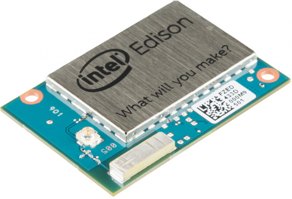
The Edison packs a host of features, including WiFi (802.11a/b/g/n), Bluetooth (4.0 and 2.1 EDR), UARTs, I2C, SPI, USB, and 40 GPIO. It’s driven by a 32-bit Intel® Atom™ Processor clocked at 500MHz, supported by 1GB of LPDDR3 RAM and 4GB eMMC flash memory. To top it off, it’s housed in a tiny, 35.5 x 25.0 x 3.9 mm module.
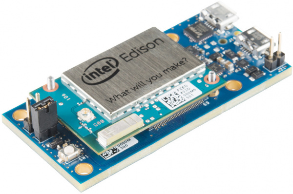
Edison iso

Top view of the Edison. The guts are covered in an RF shield. You can also see the an antenna for WiFi/Bluetooth and a u.FL connector for attaching an external antenna.

Needless to say, the Edison is a powerful, little electronics brain. It has the power to change how we all think about embedded computing. The module is equipped with a Linux OS based on Yocto, so you can compile C/C++ files, or run Python, Node.js, and other scripts.

Interfacing With the Edison

To keep the platform small, all of the I/O pins are broken out to a 70-pin Hirose DF40C connector. These fine-pitch connectors are great for keeping things small, but can be difficult to interface with. They’re board-to-board connectors, so to interface the Edison with other components you’ll need a board with a mating Hirose connector.

Currently, the mating boards available include a whole host of SparkFun Edison Blocks, the Arduino Expansion Board, and the Mini Breakout.

The Edison Blocks which (among many other boards) include the Base Block, Console Block, Console Basic Block, and Battery Block are a great way to customize your Edison project, while maintaining the minuscule form factor. Learn more about the Blocks and how they interconnect by reading our General Guide to SparkFun Blocks for Intel Edison

SparkFun Block for Intel® Edison - Battery

Out of stock DEV-13037

The Intel® Edison is an ultra small computing platform that will change the way you look at embedded electronics. Each Ediso…

$24.95
SparkFun Block for Intel® Edison - Console

In stock DEV-13039

The Intel® Edison is an ultra small computing platform that will change the way you look at embedded electronics. Each Ediso…

$29.95
SparkFun Block for Intel® Edison - Base

Pre-Order DEV-13045

The Intel® Edison is an ultra small computing platform that will change the way you look at embedded electronics. Each Ediso…

$29.95
SparkFun Block for Intel® Edison - UART

Pre-Order DEV-13040

The Intel® Edison is an ultra small computing platform that will change the way you look at embedded electronics. Each Ediso…

$24.95

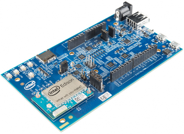
The Arduino board is a great place to start, if this is your first foray into the Edison or embedded computing.

Edison Arduino Expansion Board

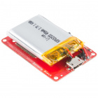
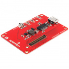
The Mini Breakout, like the SparkFun Blocks, is useful if you want to embed the Edison into a project. It includes an FTDI for interacting with the console, and it also breaks out the Edison’s USB-OTG port and a number of I/O pins.

Edison breakout

Once you have the Edison plugged into a power and console source, you can interact with the on-board Linux kernel and start developing!

Covered In This Tutorial

This tutorial is focused on getting you ready to develop on the Edison. We’ll walk you through everything from handling and powering the Edison to getting a console loaded up and connecting it to WiFi. We’ll also cover how to program the Edison through the comfy confines of Arduino.

The tutorial is split into the following sections:

What You’ll Need

  • Intel® Edison– Kind of goes without saying.
  • Base Board – Something to supply power and provide a console interface. One of the following should do:
    • SparkFun Base Block– This block is equipped with two USB connectors, which provide access to the Edison’s OTG port and UART console. This block allows everything from upgrading the firmware, and programming via Arduino, to interacting with the Linux terminal.
    • Edison Mini Breakout– This is a simple breakout for the Edison. It provides power over USB, as well as a console. A second USB connector provides you with access to the Edison’s USB OTG interface. The Edison is included with this kit!
    • Arduino Expansion Board– A bigger Edison base board, with headers broken out to the familiar Arduino footprint. If you plan to use the Edison with the Arduino IDE, this is the board you’ll want to use. It also includes an Edison!
    • SparkFun Console Block– This block is similar to the Base block, but removes the OTG USB port. This block only provides console access, you won’t be able to use it for firmware upgrade or Arduino programming.

Beyond that, you may also need to gather:

  • Micro-B USB Cable(s)– Every board above can be powered and controlled over USB, and they all use at least one micro-B USB connector. For every board except the Console, you’ll actually need two micro-B cables, in order to get the most out of your Edison.
  • Power Supply– This will depend on which base board you’re using. If you’re using an Arduino Expansion Board a 7-15V wall adapter may be required in addition to the USB cable. Our 9V Wall Adapter should do the trick.
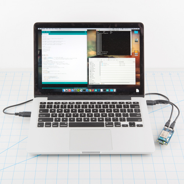
  • A computer with two available USB slots, or a hub. To upgrade the Edison’s firmware, you’ll need access to both its OTG and debug ports.
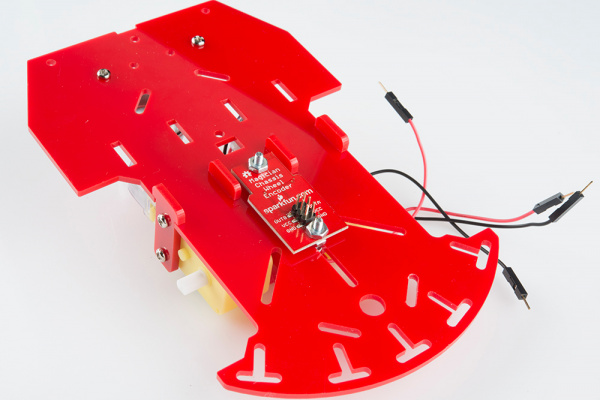
Edison development set up

That should be enough to get started developing on the Edison!

Suggested Reading

  • Serial Terminal Basics– We’ll be working with the serial terminal a lot in this tutorial. If you don’t already have a reliable terminal emulator program installed on your computer, check out this tutorial to find one you like!
  • Galileo Hookup Guide– The Galileo board works as a nice introduction to the Edison. They both run a very similar, Yocto-based Linux kernel. If you’re unfamiliar with the Galileo, or Intel processors in general, this might be a useful tutorial to check out.

Download Drivers and Arduino

Before you start plugging things in and blinking LEDs, make sure your development computer has everything it needs to work with the Edison.

The Edison is designed to work with any operating system: Windows, Mac or Linux. There are separate drivers and software for each, though, so make sure you grab the software that matches your OS.

Download Arduino

Because the Edison runs Linux and has GCC, Python, Node.js, etc., you can use a wide assortment of tools to develop on it. But, if you’re just getting started with embedded development, Arduino may be the easiest place to begin.

Using Arduino to develop on the Edison requires a custom version of the IDE. You can grab the latest version of the Arduino for Edison software by clicking the button below.

Download Arduino for Edison

There are a variety of downloads on that page, make sure you get the “Arduino Software 1.5.3 - Intel 1.0.4” (latest as of December 2014), and make sure you grab the version that matches your OS.

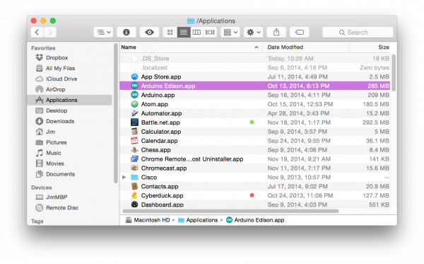
On a Mac, after downloading and unzipping the application, we recommend renaming the “Arduino” app to something like “Arduino Edison”. You may also want to move the app to your Applications folder.

Rename the Edison Arduino application

Likewise, Windows users with multiple Arduino installs should rename any shortcuts or folders to differentiate the Arduino for Edison application from the normal Arduino. This version of Arduino will not work with other, non-Intel Arduino boards.

Download and Install the FTDI Drivers (Windows and Mac)

Most Edison base boards, including the Arduino Breakout, Mini Breakout, and our Base/Console Blocks are equipped with an FTDI chip that converts USB to serial, which allows for easy access to the Edison’s UART console. To use the FTDI, download the latest VCP drivers from their downloads page.

Download the FTDI Drivers

If you need help installing the drivers, check out our How to Install FTDI Drivers tutorial.

Download and Install the Edison Drivers (Windows Only)

If your using a Windows machine to interact with your Edison, you’ll need to install drivers plural: an FTDI driver for the console and an Edison-specific driver for the Edison’s on-chip USB. The latter can be downloaded on the same Edison - Software Downloads page you were on earlier, towards the bottom of the page. Look for the “Windows Driver setup 1.0.0” link.

Download the Windows Edison Driver

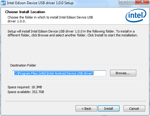
After you download this executable, run it and follow along with the install wizard to set your computer up with the drivers.

Windows driver install process

It may take a couple minutes to complete the driver installation. You should be notified that the drivers installed successfully once the process has completed.

Plugging In

Now that the drivers are installed, it’s safe to plug the Edison into your base board, and on into your computer.

Plugging the Edison Into the Base Board

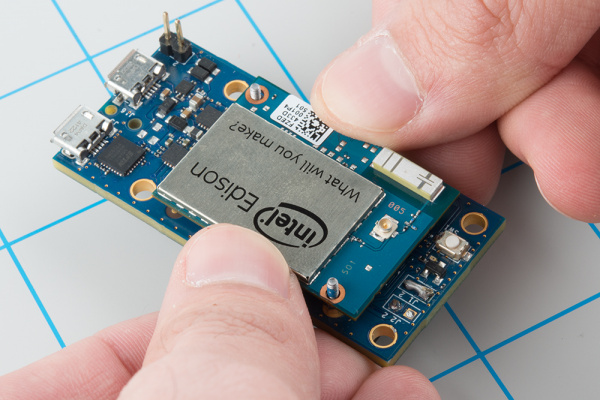
Let’s start by plugging the Edison into your base board, whatever that may be. Keep in mind that the Edison’s Hirose connectors are very delicate. When plugging your Edison into a base board, take care to push straight down, applying even pressure to the connector and the left corner of the Edison.

Plugging in Edison

If you need to remove the Edison, be equally gentile and apply even pressure.

Connecting and Powering via USB

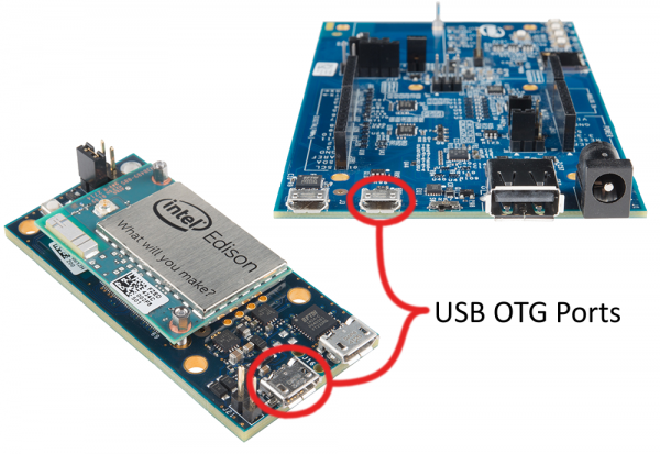
Once the Edison is cleanly seated into your base board, wire up the USB port(s) to your computer. If your base board has two USB ports, it’s recommended that you connect both up to your computer – one port provides power and direct USB access, while the other connects to the Edison’s console.

If you’re using Intel’s Arduino Expansion Board or the Mini Breakout, make sure you have at least connected USB to the Edison’s USB OTG port. That is the only port that can power the Edison.

USB OTG Ports

If you’re using a SparkFun Base Block, you can use either USB port to power the Edison. For the next step (programming an Arduino sketch), we recommend using the Edison’s OTG USB port. The two connectors are labeled on-board, so it should be easy to pick out which is which.

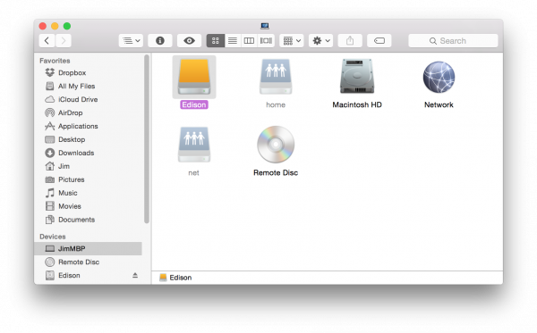
After plugging the Edison’s OTG port into your computer, there are a couple indicators that it’s ready to use. First, look for a power indicator LED on the base board to illuminate. Beyond that, after about 30 seconds, the Edison will show up as three different devices on your computer:

  1. USB Mass Storage device with around 800MB of storage space.
  2. Intel Edison Virtual Com Port, which you may be used to from the Arduino world. The port it enumerates on will be what we’ll upload our code to.
  3. Intel Edison USB RNDIS Device, a network adapter which allows your Edison to connect to the Internet through USB, using your computer as a gateway.

The removable storage device called “Edison” is the best indicator that it’s working.

Edison shows up as a removable drive

This is a great sign! It means the Edison has booted up, enumerated over USB, and is ready to be programmed.

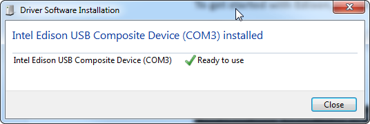
Windows users plugging their Edison in for the first time may have to wait an extra minute or so while drivers are set up. Once that’s complete, you should be notified with a handy window like this, which also passes along important information about the Edison’s COM port assignment.

Edison driver set up on Windows

Don’t forget the COM port, or, if you didn’t get the notification, check for the Edison’s COM port assignment in your device manager.

Programming the Edison in Arduino

With a built-in C-compiler, Python, Node.js, and more, the Edison is capable of amazing things. As you’ll discover in later Edison tutorials, we really recommend exploring the Edison’s full capabilities by writing your applications in C, C++, Python, or anything that takes full advantage of the Edisons capabilities.

That said, using Arduino to program the Edison is a great way to start developing on the mini-computer in a safe and familiar environment. In this section, we’ll examine how to program the Edison in Arduino, cover some common troubleshooting, and point out some useful examples to help get you started.

Note 1: This section requires a base block with a USB OTG port– that means you won’t be able to use the Arduino IDE with the Console Block. If that’s all you have, skip ahead to the Setting Up the Console section.

Note 2: if you’re using the Arduino Expansion Board, make sure the switch labeled “SW1” (between the micro-B USB port and the larger host USB port) is slid in the direction of the nearby micro-B port. That will switch that port into device mode.

Uploading Blink

By now you should have the Edison powered and plugged into your computer (connecting the Edison’s OTG USB port to your computer), drivers set up, and Arduino for Edison software installed. If not, refer back to the previous sections of this tutorial.

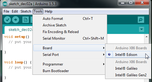
Open up the Edison-specific Arduino software. This software is nearly indistinguishable from other Arduino builds. To make sure you’re using the right version, go up to the Tools > Board menu and select Intel® Edison.

Selecting the board

You may also notice the entires for the Intel® Galileo, and a distinct lack of any other Arduino board in the list – this software only works with Intel’s boards.

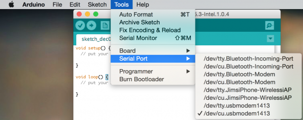
Next, select your serial port by going to Tools > Serial Port and select the COM port number that matches your new Edison.

Selecting the serial port

On Windows the serial port will come in the form of “COM#”. On Macs there will be two entries in the list for your Edison, make sure you select the one that looks something like “/dev/cu.xxxxxx” (cu not tty).

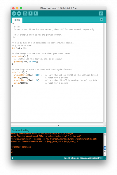
Finally open Blink by going to File > Examples > 01.Basics > Blink. And click the Upload icon.

After the compile, the code should quickly upload over to the Edison. Look for a “Transfer Complete” notification in the console window below.

Transfer complete

Don’t fret if you get an upload error! We’ve gotten a lot of them too. For most problems, there’s usually no-better a fix than the old restart. This interface can be finicky, if you get an upload error try unplugging the Edison then plugging it back in and trying again. If that doesn’t help, consider checking out Intel’s Edison forum.

Handy Examples

We’ve loaded up the blink example, but on many boards the Edison doesn’t even have an LED to blink. Here are some other handy examples that prove the Edison is working, and provide some insight into how the Edison’s Arduino interface works.

Serial

As always, the Arduino serial monitor is a handy debugging tool. Give some of the examples in the File > Examples > 04.Communication folder a try, or load up something simple like this:

language:c
void setup()
{
  Serial.begin(9600);
}

void loop()
{
  if (Serial.available())
  {
    Serial.print("Decimal value: ");
    Serial.print(Serial.read());
    Serial.println();
  }
}

Then open up the serial monitor and interact with your Edison!

WiFi

WiFi is one of the most important features embedded into the Edison, and it’s supported in the Arduino IDE by an updated WiFi library.

Try loading up any of the examples in the File > Examples > WiFi folder – the “WiFiWebClient” example is a good one. You’ll probably have to update the SSID and passkey before uploading.

Setting Up the Console

After you’ve checked out the Arduino side of the Edison, a great place to start learning about its more unique features is by interacting with the console. The console provides access to the Linux environment. You can use it to connect your Edison to a WiFi network, to write C++ programs with the vi editor, or run Python scripts.

Connecting to the FTDI Port

The Arduino Expansion Board, Edison Mini Breakout, and the SparkFun Console Blocks all route the console UART out through an FTDI chip, which converts serial to USB.

If you haven’t already, plug your Edison into the base board and power your base board (in most cases by hooking up the USB OTG port). Then connect the base board’s debug port to your computer via a USB cable. Each of these boards have two micro-B USB ports, make sure you plug into the correct one!

Make sure you have the FTDI drivers installed. If you need any help, check out our How to Install FTDI Drivers tutorial.

Opening Up a Serial Terminal Emulator

The next step is to open up your favorite terminal emulator software on your computer. If you don’t have a favorite, check out our Serial Terminal Basics tutorial.

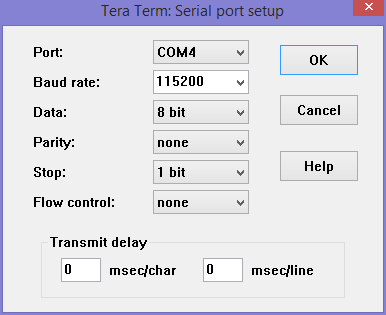
Make sure the new COM port for your base board is correctly set. You’ll also need to set the baud rate to 115200bps (8-N-1).

Console settings

After you’ve opened up the serial port, try hitting enter a couple times. If all goes well, the Edison should respond with a login prompt.

The default Edison login is root. There is no password…yet. You can run passwd, if you want to set one now, but it will be wiped out when/if you update the firmware image.

Updating the Firmware Image

Most Edison’s ship with an older version of the firmware. Updating to the latest version of the firmware equips the Edison with a whole host of new utilities, including a WiFi configuration tool and a fix to that annoying 5-second sleep in the terminal.

This step requires access to both the Edison’s OTG USB port and the console. That means you’ll need two USB cables, connected to two ports on your computer (or a hub).

Edison with both cables connected

The OTG port will give us access to the Edison’s USB mass storage device.

Download the Latest Image

We’ll begin by downloading the latest and greatest version of the Edison firmware, grab it from the Edison Software Downloads page.

Download the Edison Yocto complete image

Download the “Edison Yocto complete image” ZIP – it’s about 100 MB. Then unzip the archive, and keep the extracted contents up somewhere handy.

Out With the Old

Before you load the new firmware onto the Edison, make sure all of the old stuff is out of the way. Use your terminal (Mac) or CMD (Windows), and navigate to the top level of your Edison’s mass storage drive.

On Mac, type cd /Volumes/Edison. On Windows type E:– replacing “E” with the drive letter of your Edison.

Once inside the folder, type rm -rf * and rm -rf \.* to remove all of the files – hidden or not – from the drive.

In With the New

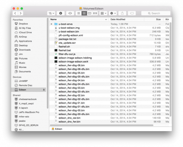
Next, open up the Edison mass storage drive in your file explorer. Then move everything from within the extracted ZIP folder into the drive. It should look a little something like this:

Contents ready to flash on drive

Notice that there are an assortment of bin’s and other files at the top level of the drive, not within a folder within the top level.

Issuing the Update Command

Finally, begin the update by opening your Edison’s console and entering this command: reboot ota.

The Edison will shut down, then, as it begins to reboot, it will notice there’s a flash update in the mass storage device and begin to install the update. The update will take a minute-or-so to install, and the Edison will reboot one last time.

When the Edison comes back up, log in as root and take comfort in knowing your Edison is running the latest and greatest version of the Edison Yocto image.

Connecting to WiFi

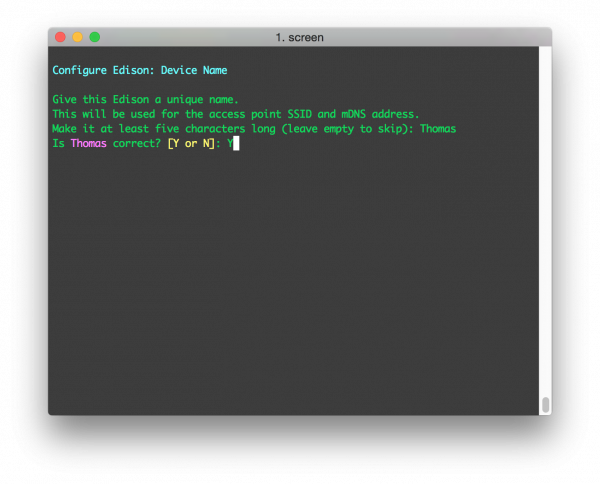
The latest version of the Edison firmware includes a handy utility to set up WiFi – configure_edison --setup. Type that into your Edison’s console, then follow the in-terminal directions as you can edit the Edison’s name and WiFi settings.

First give your Edison a unique name:

Naming the Edison

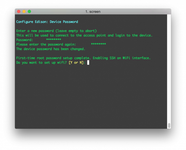
Then, if you so desire, assign a password to your root user:

Passwording the Edison

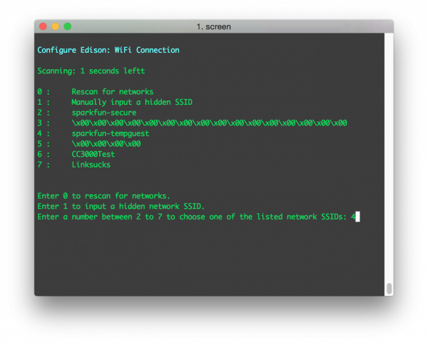
Finally we get to the reason we’re here. Type ‘Y’ to jump into the WiFi setup utility. The Edison will scan for nearby wireless networks, after a few seconds it will list the results.

Scanning for networks

Type a number to pick an SSID, then enter your passkey and wait for it to (try to) connect.

Connected to a network

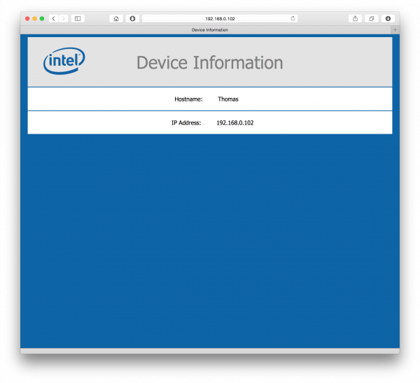
The last line of the configure utility will prompt you to open your browser and point to the Edison’s local IP.

Device information page

You won’t glean a lot of information from this page, but it will provide some assurance that your Edison is on the WiFi network. Plus, just think of all the fun you can have with a tiny little credit card-sized computer that can serve up web pages like this!

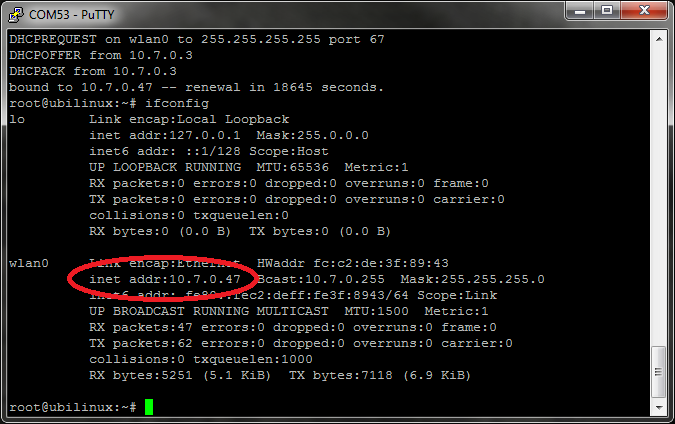
You can use the console for other network-related stuff now, too. Try pinging your favorite web site with a command like ping sparkfun.com -c 4. Or check your network status with a command like ifconfig or ifconfig wlan0.

Now that your Edison’s on the WiFi network, you can do all sorts of cool stuff. How about SSH-ing into it, so you can remotely interact with little computer’s file structure?

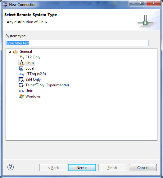
SSH-ing into the Edison

If you’ve gotten this far, you may begin to realize that interacting with your Edison via the command line may get a bit tiresome. Luckily, now that you have WiFi set up, you can (figuratively literally) cut the cord and control your Edison through the network using SSH (Secure Shell). You can even download and upload files to the Edison over SFTP (SSH file transfer protocol).

In order to SSH into your Edison, you’ll probably another piece of software installed on your computer. We like WinSCP for Windows machines and Cyberduck on the Mac.

Using WinSCP (Windows)

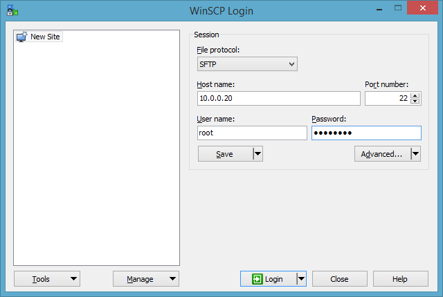
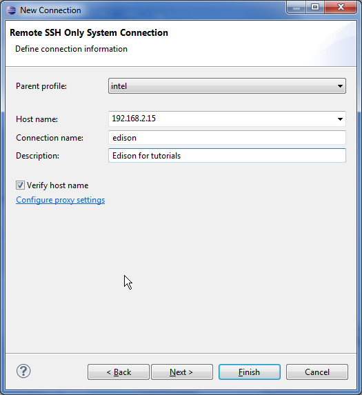
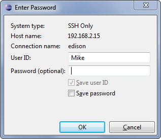
When you open WinSCP, it’ll ask you where and how you’d like to log in. Make sure “File Protocol” is set to “SFTP”. Then, in the “Host name” text box, type the IP address of your Edison. For the “User name” and “Password” boxes, type “root” and the password you set (or leave it blank if you skipped that part).

WinSCP SSH example

(Personal frustration note: if you’re having trouble SSH-ing into your Edison, you may need to turn off your Windows Firewall. Hopefully you don’t have to ram your head against that wall for too long. Active VPN’s may also get in the way!)

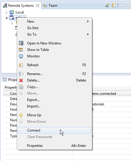
Once you click “Login”, the program will attempt to remotely log in to your Edison. If it’s successful, you’ll be greeted with a file browser. These are the actual files living on your Edison! You can use this browser to upload or download files. This is a great utility if you’re developing programs to be run on the Edison, your only other option is monochrome vi in the terminal (which would be pretty hardcore).

WinSCP also includes a utility for interacting with the remote host via a terminal. Go to “Commands” >“Open Terminal” and you’ll be right back to the console.

Using Cyberduck (Mac)

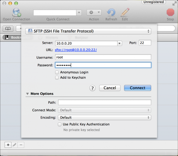
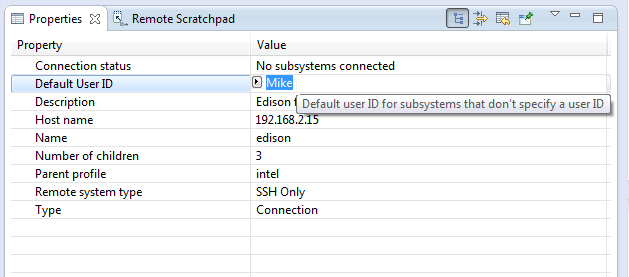
It’ll be the same idea in Cyberduck. Type your Edison’s IP address into the “Server” box. Then type “root” as the “Username” and your password if you set one. Then hit “Connect.”

Cyberduck example

Like WinSCP, Cyberduck will present you with a file explorer. This will allow for an easy, graphical interace for managing your Edison’s files.

If you’d like to interact with the console remotely, open up your Mac’s terminal application. Then type ssh root@10.0.0.20, making sure to sub in your Edison’s IP address. When/if prompted for a password, type that in, then you’re back to the Edison console.

Resources & Going Further

Now that you’ve got an Edison connected to the web, what’s next? Need some inspiration? Check out these tutorials

New!

SparkFun Blocks for Intel Edison - Battery Block

A quick overview of the features of the Battery Block.
New!

SparkFun Blocks for Intel Edison - Console Block

A quick overview of the features of the Console Block.
New!

Loading Debian (Ubilinux) on the Edison

How to load a Debian distribution (specifically Ubilinux) onto the Edison.

If you’re new to Linux, we highly recommend checking Userland, a guide to all things shell.


learn.sparkfun.com |CC BY-SA 3.0 | SparkFun Electronics | Niwot, Colorado

Loading Debian (Ubilinux) on the Edison

$
0
0

Loading Debian (Ubilinux) on the Edison a learn.sparkfun.com tutorial

Available online at: http://sfe.io/t334

Introduction

If you have been playing with the Edison, you might have noticed that the Yocto Project can be difficult to work with. Namely, they want you to re-build Linux from scratch every time you need to enable a package. This is great if you are making the Edison into end product, and you need a fast, stripped-down version of Linux. However, if you want more features and a full-fledged package manager, it is worth installing a different version of Linux on the Edison.

Intel Edison with Debian

For this tutorial, we are going to install Ubilinux on Edison and enable a few important features (like WiFi). Ubilinux is a custom Linux image based on Debian. This version of Linux was used in the SparkFun Live! episode Tweeting Turkey Temperature Timer.

You will need an Intel Edison and one of the boards that allow you to re-program the Edison, such as the SparkFun Base Block, the Mini Breakout Kit, or the Arduino Breakout Kit.

Suggested Reading

Install Ubilinux

We need to download the Ubilinux image, which we will install on the Edison, and some software depending on your current operating system.

IMPORTANT: Make sure the Edison is not powered or connected to your host computer at this time.

Windows

Download and install 7-zip from the 7-zip.org page. You will probably want the .msi version.

Download dfu-util for Windows (this executable came from the spark.io community).

Download the Ubilinux image by navigating to http://www.emutexlabs.com/ubilinux and click on “ubilinux for Edison.”

Go to Start → All Programs → 7-Zip → 7-Zip File Manager. Within the file manager, navigate to your downloads folder. Select “dfu-util-0.8-binaries.tar.zx” and select “Extract.”

Unzipping dfu-util in Windows

Click “OK” when prompted on where to extract the files to accept the defaults. “dfu-util-0.8.binaries.tar” will appear in the 7-Zip File Manager. Double-click on it to enter the folder. Select “dfu-util-0.8-binaries.tar” and click “Extract” to extract dfu-util one more time.

Untarring dfu-util in Windows

Click “OK” when prompted again. Press the “Up One Folder” button to navigate back to your Downloads folder.

7-Zip up one folder

Perform the same steps again to extract the Ubilinux image:

  • Select the ubilinux-edison-XXXXXX.tar.gz file
  • Click “Extract”
  • Click “OK” on the pop-up box
  • Wait while that extracts
  • Double-click on “ubilinux-edison-XXXXXX.tar” to enter into the tar archive
  • Select ubilinux-edison-XXXXXX.tar file
  • Click “Extract”
  • Wait once more while that extracts

7-Zip to unzip Ubilinux image

Open up a File Explorer window and navigate to <YOUR DOWNLOADS FOLDER>\dfu-util-0.8-binaries.tar\dfu-util-0.8-binaries\dfu-util-0.8-binaries\win32-mingw32. Right-click on dfu-util.exe and click “Copy.”

Copy dfu-util in Windows

Navigate to the toFlash folder, which is in the unzipped Ubilinux folder (<YOUR DOWNLOADS FOLDER>\ubilinux-edison-141030.tar\ubilinux-edison-141030\toFlash). Right-click and select “Paste” to paste in the dfu-util.exe file.

Paste in dfu-util

In the \toFlash folder, scroll down to find the file “flashall.bat.” Double-click it to start the install process.

Windows run flashall.bat

A command window will open up and ask you to plug in your Edison.

Windows plug in Edison

Plug in your Edison (Use J16 for the Intel Arduino and Mini-Breakout boards. Use “OTG” for the SparkFun Edison Base Block), and the installation process will begin!

Windows installing Ubilinux

WARNING: Once the command prompt window closes, you will need to wait at least 2 minutes for the installation to complete. The Edison should reset a couple of times to finalize its installation. Do not unplug the Edison! It’s probably a good idea to walk away for those 2 minutes.

Mac OSX

Download the Ubilinux image by navigating to http://www.emutexlabs.com/ubilinux and click on “ubilinux for Edison.”

Open a terminal (Finder → Applications → Utilities → Terminal).

OS X Terminal application

Change to your downloads directory:

cd Downloads

Extract the contents of the downloaded file:

tar xvfz ubilinux-edison-XXXXXX.tar.gz

Note that the version number (XXXXXX) will be whichever version you downloaded (e.g. ubilinux-edison-141030.tar.gz).

Move into the “toFlash” directory:

cd toFlash

Run the install script:

sudo ./flashall.sh

You will see a message like “Now waiting for dfu device.” At that, plug in your Edison (Use J16 for the Intel Arduino and Mini-Breakout boards. Use “OTG” for the SparkFun Edison Base Block). You should see the script start to flash the Edison in the terminal. Wait while that finishes (it could take a few minutes).

Flashing Ubilinux on Mac OS X

Once the flashing process is complete, you will get a message like “Your board needs to reboot twice to complete the flashing procedure, please do not unplug it for 2 minutes.” You will want to wait those 2 minutes to make sure the flashing process is complete.

Linux

Download the Ubilinux image by navigating to http://www.emutexlabs.com/ubilinux and click on “ubilinux for Edison.”

Open a terminal and navigate to your downloads directory. For example:

cd Downloads

Extract the contents of the downloaded file:

tar xvfz ubilinux-edison-XXXXXX.tar.gz

Note that the version number (XXXXXX) will be whichever version you downloaded (e.g. ubilinux-edison-141030.tar.gz).

Move into the “toFlash” directory:

cd toFlash

Run the install script:

sudo ./flashall.sh

You will see a message like “Now waiting for dfu device.” At that, plug in your Edison (Use J16 for the Intel Arduino and Mini-Breakout boards. Use “OTG” for the SparkFun Edison Base Block). You should see the script start to flash the Edison in the terminal. Wait while that finishes (it could take a few minutes).

Installing Ubilinux from Ubuntu

Once the flashing process is complete, you will get a message like “Your board needs to reboot twice to complete the flashing procedure, please do not unplug it for 2 minutes.” You probably want to wait that 2 minutes (I know I would not want to risk bricking my Edison).

Log Into Ubilinux

Once you have flashed your Edison, you can log in over a serial connection.

IMPORTANT: If you are using the Intel Arduino or Mini-Breakout board, plug in the other USB cable at this time (you should have 2 USB cables running from your Edison to your computer). If you are using one of the SparkFun Edison Blocks with a “Console” port, you can use that port to power the Edison and receive a serial console.

Edison with Intel Arduino breakout board

You will need to use both USB ports on the Arduino Breakout board

Edison with SparkFun Base Block

You only need to use the USB port labeled “Console” on the Base Block

Windows

Download a serial terminal, such as PuTTY.

You will also likely need to download and install the Virtual COM Port Drivers from FTDI (download the “setup executable” version).

Open the Device Manager. Expand “Ports (COM & LPT)” and you should see a “USB Serial Port.” Make a note of the COM number.

Finding the COM port number on Windows

Run PuTTY, select the “Serial” option, change the COM port number under “Serial line,” and set the “Speed” to 115200.

Using PuTTY

Click “Open.” You will see a blank terminal. Hit ‘enter’ and you will be prompted with a login screen.

Logging into Ubilinux using Windows

Enter the default login credentials:

ubilinux login: edison
Password: edison

And that’s it! You are now logged into Ubilinux running on your Edison.

Mac OSX

Before you plug in your Edison, you need to find the location of the USB serial device. Open a terminal and enter:

ls /dev/tty.usb*

Make a note of which devices appear. Plug in your Edison (both cables for Intel breakout boards or the “Console” port for the SparkFun Blocks) and enter the command again:

ls /dev/tty.usb*

An extra file should appear. Remember the file name and use the screen command to connect:

screen /dev/tty.usbserial-XXXXXXXX 115200

Where -XXXXXXXX is the string of numbers and letters of the USB serial device. For example:

Using screen on OS X

Press ‘enter’ to see the login screen.

Logging in to Ubilinux on OS X

Enter the default login credentials:

ubilinux login: edison
Password: edison

You should now be logged into Ubilinux.

Linux

Open a terminal and connect using the screen command:

sudo screen /dev/ttyUSB0 115200

Note that your USB serial device may not be exactly ttyUSB0. If you have other USB serial devices plugged in, it could be ttyUSB1, ttyUSB2, and so on.

Press ‘enter’ to see the login screen.

Logging into Ubilinix using Linux

Enter the default login credentials:

ubilinux login: edison
Password: edison

You should now be logged into Ubilinux.

Add Some Security

By default, Ubilinux gives you access to the root account and a user account called “edison.” This is a great starting point, as it allows you to do anything in the operating system. However, it is not secure. If someone finds out the IP address of the Edison, they could log in with the default username and password.

One of the easiest fixes for improving security is to create a unique user account, change the edison user password (or delete the whole account!), and change the root password. You can skip creating a new user if you like, but it is still highly recommended that you change passwords for both root and edison.

If you are logged in on the “edison” account, run:

logout

At the login screen, log back in using the root account:

ubilinux login: root
Password: edison

Create a New User

Choose a username for your new account and think of a memorable password. Run the command:

adduser --ingroup users <USERNAME>

You will be prompted to enter your password twice and asked for some identifying information. Feel free to fill them in or hit ‘enter’ to accept the default of blank (no information). Type ‘y’ and press ‘enter’ when prompted about the information being correct.

Adding a user in ubilinux

Change the “edison” Account

It is advisable that you either remove the “edison” account or at least change the password.

Change Password

If you want to keep the “edison” account, then you should consider changing the password to something more secure:

passwd edison

You will be prompted to enter the new password twice.

Remove Account

The better option is to remove the account altogether, as guessing a non-default username is more difficult. While logged in as root, enter:

deluser --remove-home edison

Change root Password

The last step is changing the default root password. This is crucial in preventing unauthorized people from easily signing in to your Edison with root access. While logged in as root, run the command:

passwd

You will be prompted to enter the new password twice.

Enable WiFi

After logging into Ubilinux, you will probably want an Internet connection so you can download and install packages at your whim. There are a few ways to connect to the Internet over WiFi. We will show two of them. The first one is the quick and easy way, but it leaves your WiFi password stored in plain text in a file. The second is the preferred method, as it encrypts your password, but the steps are slightly more involved.

If you are logged in as a regular user, run the command:

su

And enter the password for root to gain superuser abilities. As a side note, “su” stands for substitute user.

Quick and Dirty

The easiest way to get on a local WiFi Access Point is to store the SSID and password in a file. The problem is that your password will be stored in plain text, so it is not very secure.

Use your favorite Linux text editor (I’m still a fan of nano) to open the interfaces file:

nano /etc/network/interfaces

Use the arrow keys to navigate to “auto usb0” and add a “#” in front of the line to comment it out.

Navigate down and remove the “#” in front of “auto wlan0” so that our Edison will try to automatically connect to WiFi on boot.

Go down to the “wpa-ssid” and “wpa-psk” lines. Change the default SSID and password (PSK) to your desired WiFi SSID and password.

Change interfaces file to connect to WiFi

Press ‘Ctrl-X’ to exit and press ‘y’ to save the file when prompted.

We recommend following the directions in “The Better Way” below, but if you are happy with the quick method, skip to “Test WiFi Connection.”

The Better Way

We can store our WiFi password more securely by creating a hash and locking down the /etc/network/interfaces file so that only root has access to it.

With the root account, change the permissions of the /etc/network/interfaces file:

chmod 0600 /etc/network/interfaces

Create a hash of your WiFi password:

wpa_passphrase <YOUR_WIFI_SSID> <YOUR_WIFI_PASSWORD>

That will print out a “network” section in the console.

Using wpa_passphrase to create a hash

Copy the long string of letters and numbers after “psk=” (On PuTTY and many Linux consoles, you just need to highlight the string to copy it). Open the /etc/network/interfaces file:

nano /etc/network/interfaces

Use the arrow keys to navigate to “auto usb0” and add a “#” in front of the line to comment it out.

Navigate down and remove the “#” in front of “auto wlan0” so that our Edison will try to automatically connect to WiFi on boot.

Go down to the “wpa-ssid” line. Change the default SSID to your WiFi’s SSID.

Move your cursor to the “wpa-psk” line, delete the default string after “wpa-psk,” and paste in the long hash that we generated earlier (you just need to right-click for PuTTY and many other Linux consoles).

Add hash to PSK in interfaces file

Press ‘Ctrl-X’ to exit and press ‘y’ to save the file when prompted.

Test WiFi Connection

Restart the wireless driver by entering:

ifup wlan0

Once that configures, your Edison should be connected to your local WiFi. You can check by entering:

ifconfig

You should see an “inet addr” entry under “wlan0” that shows your IP Address.

Ubilinux ifconfig command

To ensure you have access to the Internet, you can ping a known site, such as www.google.com or www.sparkfun.com:

ping www.sparkfun.com

You should see several pings and responses. Press ‘Ctrl-C’ to stop.

Pinging sparkfun.com

Now that your Edison is connected to a network, you can use SSH to connect to your Edison from another computer. You just need to know the IP Address.

Using apt-get

Installing Packages

The first thing we want to do is update our package manager with apt-get. Make sure you are logged in as root (or use the “su” command), and enter:

apt-get update

Wait while that downloads and updates your package lists.

If you want to install a package, like sl, you just need to apt-get install:

apt-get install sl

If prompted, press ‘y’ when asked to install the package, and your package will be automatically downloaded and installed!

NOTE:“sl” installs a fun little demo. Enter:

/usr/games/sl

To see it!

Bonus: Adding "sudo"

This part is completely optional. Some people like to use the “sudo” command in order to execute actions that require superuser privileges (such as “sudo apt-get install”). Others prefer to switch users with “su” to execute commands. It is an ongoing debate.

If you would like to add the sudo command, we first need to install it. With the root account, run the command:

apt-get install sudo

Add your user account (not root!) to the sudo group:

adduser <YOUR_USERNAME> sudo

Logout with the “logout” command (you might have to type it twice if you are using “su”):

logout

Log back in with your regular user account. Try a command such as:

ifconfig

You should get an error like “-bash: ifconfig: command not found.” Try the same command again with “sudo” in front:

sudo ifconfig

You should get a print out of your network status.

Testing sudo in Ubilinux

You can now use sudo to run commands that require administrative privileges without having to log in to your root account. It lowers security some by allowing a regular user to run commands with escalated privileges. However, it means that you do not need to sign into your root account if you are using something like SSH.

Ideally, you would figure out which commands your user account would need to run and enable only those in the sudoers file. This can be done with the “visudo” command. To learn more about how to edit the sudoers file, read this article.

Troubleshooting

dfu-util not found

On Linux, if you get an error like “dfu-util: command not found” when trying to install Ubilinux then you need to install dfu-util. Run the command:

sudo apt-get install dfu-util

Which USB port do I use?

For installing Ubilinux, if you are using the Intel Arduino Breakout or Mini-Breakout, you need to use the USB port labeled “J16.” If you are using the SparkFun Edison Base Block, use the port labeled “OTG.”

For logging into Ubilinux, you need to use both USB ports on the Intel Arduino or Mini-Breakout. You only need to use the port labeled “Console” on the SparkFun Base Block.

libusb not found

In Windows, if you see an error message such as “The program can’t start because libusb-1.0.dll is missing from your computer”, then you need libusb-1.0.dll, which can be found in the dfu-util download. Navigate to <YOUR DOWNLOADS FOLDER>\dfu-util-0.8-binaries.tar\dfu-util-0.8-binaries\dfu-util-0.8-binaries\win32-mingw32. Right-click on libusb-1.0.dll and click “Copy.”

Copy libusb

Navigate to <YOUR DOWNLOADS FOLDER>\ubilinux-edison-141030.tar\ubilinux-edison-141030\toFlash. Right-click and select “Paste” to paste in the libusb-1.0.dll file.

Paste libusb

NOTE: You can permanently install dfu-util.exe and libusb-1.0.dll on your Windows computer if you like. Read into modifying PATH and installing a .dll. For now, they were just copied into the Ubilinux path for brevity.

Packages not found

On Linux, a message such as “E: Unable to locate package” could mean a few things:

  • You are spelling the package name wrong (I am guilty of this quite often)
  • Your package lists cannot find the package (try modifying /etc/apt/sources.list to point to other repositories
  • The package simply does not exist. You might have to install whatever it is from source.

Sudo Unable to resolve host

If you use the “sudo” command and get an error like:

sudo: unable to resolve host ubilinux

Then it means that the hostname of your Edison (in the file /etc/hostname) is not found in the /etc/hosts file. Open up an editor:

sudo nano /etc/hostname

And make a note of the name (it should be “ubilinux” by default). You can change it if you would like (it will change the name of your Edison when it is connected to a network).

Exit and open up /etc/hosts:

sudo nano /etc/hosts

And add your hostname (e.g. “ubilinux”) afte “localhost” in the first line.

Changing /etc/hosts file in Edison

Save and exit with “Ctrl-X” and ‘y.’ Restart the Edison with:

sudo reboot

You should no longer get the warning with sudo.

Resources and Going Further

Now that you have Debian installed on your Edison, you have many tools at your disposal. For example, aptitude is a powerful package manager that lets you install libraries and Linux packages from the Internet.

Resources

Here are some additional resources to help you with the Edison:

If you’re new to Linux, we highly recommend checking Userland, a guide to all things shell.


learn.sparkfun.com |CC BY-SA 3.0 | SparkFun Electronics | Niwot, Colorado

SparkFun Blocks for Intel Edison - Console Block

$
0
0

SparkFun Blocks for Intel Edison - Console Block a learn.sparkfun.com tutorial

Available online at: http://sfe.io/t312

Introduction

The Console Block is one of the simplest ways to power and communicate with an Intel Edison. Utilizing the FTDI 231X, this creates a USB to serial bridge that is level shifted to the proper 1.8V required by the Edison. The Console is found on UART2. This block is also capable of providing power to the Edison as well as other stacked Blocks.

alt text

Console Block

Suggested Reading

If you are unfamiliar with Blocks, take a look at the General Guide to Sparkfun Blocks for Intel Edison.

Other tutorials that may help you on your Edison adventure include:

Board Overview

alt text

Console Block Functional Diagram TOP

  • USB Micro B - The USB port provides power and a console access port to an Intel Edison Stack. This Block supplies a voltage to the Edison and other Blocks through the VSYS line at 4V. This voltage may vary up to +/-0.1V depending on load.

  • Power Button - The power switch is connected to the “PWRBTN” line on the Edison. This give the user the ability to place an Edison in sleep or power down the module completely. This does not affect power to other Blocks in the stack.

  • Power LED - The power LED illuminates when power is present on VSYS. This can come from the Console Block, or any other powered Block in the stack.

  • Data LEDs - The Data LEDs help the user identify if the console is active. This is a feature commonly found on our FTDI breakout.

  • LED Jumpers - If power consumption is an issue, cut each jumper to disable LEDs

  • Expansion Header - The 70-pin Expansion header breaks out the functionality of the Intel Edison. This header also passes signals and power throughout the stack. These function much like an Arduino Shield.

Using the Console Block

To use the console Block, simply attach an Intel Edison to the back of the board, or add it to your current stack. Blocks can be stacked without hardware but it leaves the expansion connectors unprotected from mechanical stress.

alt text

Console Block Installed

We have a nice Hardware Pack available that gives enough hardware to secure three blocks and an Edison.

alt text

Intel Edison Hardware Pack

Connecting to the Console

Once you have connected your hardware, plug the Micro USB cable into the Block. If you do not have FTDI drivers currently installed, you’ll need to download and install them before using your Edison. Visit our tutorial for instructions on how to install the drivers. After you have ensured that the drivers are installed and your device is running, open your favorite terminal program and point it to the USB-serial connection. We have another tutorial to explain terminal programs and how to use them.

The standard Baud Rate is 115200bps.

Once a terminal is active you are ready to explore!

alt text

Using the Power Button

The power button on the Edison brings a unique feature commonly not found on single board computers. The power button behaves much like the power buttons on desktop and laptop computers.

  • While powered, Holding the power button for ~10 seconds will power down the Edison.
  • While un-powered, pressing the power button momentarily will reboot the Edison.
  • While powered, pressing the power button momentarily will place the Edison in sleep mode.
  • While in sleep mode, pressing the power button momentarily will wake the Edison.

Resources and Going Further

Now that you have had a brief overview of the Console Block, take a look at some of these other tutorials. These tutorials cover programming, Block stacking, and interfacing with the Intel Edison ecosystems.

Edison General Topics:

Block Specific Topics:


learn.sparkfun.com |CC BY-SA 3.0 | SparkFun Electronics | Niwot, Colorado

Decade Resistance Box Hookup Guide

$
0
0

Decade Resistance Box Hookup Guide a learn.sparkfun.com tutorial

Available online at: http://sfe.io/t300

Introduction

A decade box is a tool that contains resistors of many values accessed via mechanical switches. Adjust the knobs to output any of the discrete resistances offered by the box.

Decade Resistance Box

They are known as decade boxes because they have controls that correspond to the digits in a decimal number - a control for the ones position, a control for the tens position, a control for the hundreds position, and so on.

Reading a Decade Box

Traditional decade boxes looked like something out of Dr. Frankenstein’s lab - large wooden enclosures, with engraved front panels and big Bakelite knobs. They were available in three main types - resistance, capacitance and inductance. This kit is for a decade resistance box. It allows you to quickly and accurately dial in a specific resistance value between 0 and 999,990 &ohm;, in 10 &ohm; increments..

In this hookup guide, we’ll first assemble the decade box, then explore its application as a design aid and a test instrument.

Necessary Tools

Additional Tools and Supplies

Optional Materials

The decade box can be assembled to fit in an enclosure or behind a front panel. In this tutorial, we’ll build it into a cast aluminum enclosure.

432,640 Ohms, Anyone?

If you want to build yours into an enclosure, you’ll need the following.

  • Aluminum enclosure
  • Removable tape, such as painter’s or gaffer’s tape
  • Center Punch and hammer
  • A vise or clamps
  • A drill press or hand drill
  • A set of drill bits, or a step-drill

Suggested Reading

Enclosure Drilling

The decade resistance can be mounted in an enclosure, or used without one. If you want to put it in an enclosure, it is easiest to prepare the enclosure before the board is assembled.

If you aren’t going to use an enclosure, you can skip ahead to the next section.

For this guide, we’ll be using a small aluminum enclosure, because they are durable, and aluminum is easy to drill.

Marking

The PCB for the decade resistance does double duty as a drilling template. Each of the holes needed in the enclosure has a matching hole in the PCB.

To use the template, tape the PCB onto the enclosure, with equal spacing to each edge.

PCB Template

Mark the center of each of the holes with a center punch. Tap it with a hammer so it leaves a small divot - the divot will serve to guide the bit when you start drilling. There will be five marks for the rotary switches, and two more for the banana jacks.

Center Punch

The oval holes for the banana jacks won’t be as precise a guide for the punch - it’s OK to gauge the center of those holes by eye.

Drilling

Before we start drilling, let’s take a moment to review some basic drilling safety practices, which apply whether you’re using a hand drill or a drill press.

  1. Drilling aluminum produces small, sharp pieces of metal (“curliqueues” or “chips” as machinists call them). Safety glasses or a face shield are essential, and work gloves help protect your fingertips.

  2. The bit can bind in the material, and cause the box to spin on the end of the bit. This is dangerous, as it can damage the box, the bit, and your fingers. Secure the box with a vise or clamps before drilling!

  3. A little lubricant can help the bit cut more smoothly, and prevents dulling. There are specialty machinist’s bit lubricants, but if you don’t have them handy, a few drops of light household oil will help.

If you’re using regular bits, start with smaller ones, then work up to larger ones. We began with a 1/8" bit to make pilot holes on each of the center punch marks, then worked progressively up to larger bits. The five holes for the rotary switches should be drilled to 3/8".

The two banana connectors fit in 5/16" holes. Lacking a 5/16" bit, we drilled them to ¼", then filed the holes until the connectors fit.

If you’re not enthusiastic about all of those bit changes, consider using a stepped drill bit, such as the Irwin Unibit.

Once the holes are drilled, consider using a countersink to deburr and bevel the holes, to remove any sharp edges left by the drilling.

Labeling

In the decade box GitHub repository, there is an SVG file of the panel legend. If you have access to a laser engraver, you can etch it into the enclosure.

If you aren’t lucky enough to have access to a laser cutter, you can simply print it on paper, trim it to fit, and stick it on with adhesive tape.

paper label

Electrical Assembly

Bill Of Materials

Before we start soldering, let’s verify that all of the parts are present in the kit.

Parts Spread

As shown above, you should have the following (clockwise from top-left)

  • One Decade Resistance Box PCB
  • Nine 10 &ohm; Resistors (Brown - Black - Black - Gold - Brown)
  • Nine 100 &ohm; Resistors (Brown - Black - Black - Black - Gold)
  • Nine 1000 &ohm; Resistors (Brown - Black - Black - Brown - Gold)
  • Nine 100K &ohm; Resistors (Brown - Black - Black - Orange - Gold)
  • Nine 10K &ohm; Resistors (Brown - Black - Black - Red - Gold)
  • One red banana jack
  • One black banana jack
  • Five 1-pole 10-position rotary switches, each with a dress washer and hex nut

Electronic Assembly

For the most part, the assembly of the decade resistance PCB is straight forward. We’ll cover a few extra tips and tricks as we go along.

The first thing to note is that the PCB has definite top and bottom sides. The components are placed on the top of the board, which is marked with symbols for each component - tick marks for the resistors, and oblong outlines for the rotary switches. The components are soldered to the back of the board. The copper solder pads are only exposed on the back side - if you’re having trouble getting the solder to stick, doublecheck that you’re working on the correct side.

Soldering Resistors

Unlike many other soldering kits where the resistors lie flat on the PCB, the resistors on the decade resistance will be installed in a “standing up” orientation. This saves space on the PCB, and is commonly used in devices like guitar pedals and transistor radios.

To fit the resistor to the board, bend one lead sharply at the end of the body, doubling back 180°, so the overall result looks like a hairpin.

Bent Resistor

Then insert the resistor into the board, and splay the leads so they hold it in place while you solder.

Bent Leads

After soldering each resistor, trim the leads close to the solder fillet.

There are nine pieces of each of five different resistance values in the kit. Each value will be installed adjacent to each rotary switch. Each row is labeled with the value to be installed there.

Resistor Placement

If you’re unsure about reading the stripes on the resistors, you can use a multimeter to verify their value.

Soldering Rotary Switches

After the resistors are in place, install the rotary switches. The rotary switches fit within the matching outlines on the board. The footprint is slightly asymmetrical, so they only fit the PCB in one orientation.

Rotary Switch Orientation

The five switches are all the same, and interchangable on the PCB. Insert them into the footprint, and solder all eleven leads in place. If you’re going to put the decade box in an enclosure, ensure that the switches sit flat on the surface of the board before soldering.

Finally, the center pin of each rotary is longer than the others. You can snip this off with cutters after soldering.

Binding Posts

If you’re installing the decade resistance in an enclosure, skip ahead to the next section. You’ll mount the jacks to the enclosure, rather than the PCB!

Before we install them, let’s take a moment to look at how the banana jacks go together. The back side of the jack is threaded, with a large nut that holds the jack in place. However, this only provides the mechanical mounting of the jack. If you look closely, there are a pair of smaller nuts on the tail of the jack. The outer of these nuts is for electrical connection, and the inner nut holds the jack together. To use the jack, we first need to make sure that the inner nut is snug against the body so the jack doesn’t come apart. We’ll then use both the mounting and electrical connections.

Even though there are red and black jacks, the decade box has no specific polarity - it doesn’t matter which one is mounted in which hole. The color coding is just a convention that can be useful to trace connections on a busy workbench.

Banana Closeup

First, remove the larger nut from the jack, then insert the jack through the PCB, and reinstall the nut. Take care to not over-tighten, or you can strip the plastic threads.

Once the jack is securely mounted, take a 2 inch piece of solid-core wire, and strip the ends. Bend one end into a question-mark shaped curl.

Wire Attachment

Loop the curl around the metal end of the binding post, and tighten the small nut to hold it in place. This is much easier to do if the curl points in the clockwise direction. Otherwise, tightening the nut will cause the wire to uncurl and come off the post.

With the wire secured to the post, solder the other end of the wire to the nearby PCB pad.

Wire To PCB Pad

With the first jack mounted, repeat this for the other jack.

With all of this complete, your decade box should look like this

complete Decade Resistance

Installation In Enclosure

If you have opted to put your kit in an enclosure, the assembly changes a bit.

First, the rotary switches have an alignment tab that sticks up, and prevents them from mounting flush behind the panel. With a small pair of pliers, simply bend the tab so the switch body lies against the backside of the panel.

Flattening The Tab

The binding posts are also mounted somewhat differently. Secure them to the panel of the enclosure, rather than the PCB.

Bananas in Panel

Then install the wires on the back of the binding posts. Run the wires through the oblong holes in the PCB, and solder them in place.

Wires To PCB

Carefully pull the wire slack through the holes, as you slide the PCB into the enclosure. The rotary switches will protrude through the corresponding holes in the enclosure, and the tails of the binding posts will barely stick through the oval holes in the PCB.

PCB In Place

Secure the PCB in the box by mounting each rotary switch with the dress washer and hex nut. You can use pliers or a 12mm socket to tighten the nut.

Fastening The Switch

Finally, put the back on the enclosure, and attach the knobs. If you’re using the knobs recommended above, the set screw will tighten against the flat side of the shaft, 180° opposite the indicator.

Securing The Knobs

Quick Test

With the assembly complete, you can give the decade resistance a quick test with a multimeter. Select the resistance scale on the meter, and measure between the binding posts.

With five switches that can each take ten positions, there are 100,000 combinations! We couldn’t call this section a “quick test” if we were going to try to hit all possible settings, so we’ll use a streamlined approach instead. We’ll verify that every switch and every resistor is properly installed and functional. If they’re right in isolation, we can extrapolate that they’ll be right in combination.

  1. Start with all of the rotary switches at zero. You should measure close to zero ohms on the meter.
  2. Select the 10’s position switch, and click it through each of it’s steps. The meter should read an additional ten ohms for each click of the switch.
  3. After you have measured the top position (90 &ohm;), reset the switch to zero.
  4. Repeat the above steps for each of the other rotary switches.

A Note On Accuracy

It’s worth mentioning that the meter readings in the above test will not absolutely match the settings on the decade box. For instance, the 90 &ohm; setting might read as 89.3 or 90.5 - very close to the ideal value, but not perfect. There are a couple factors that contribute to this.

  1. First, there is a tiny amount of intrinsic resistance in the circuit. The leads of the multimeter, the traces of the PCB, and other components are not ideal conductors, and exhibit a small amount of “parasitic resistance.” In practice, it’s small enough to be negligible. If the all zero setting is higher than an Ohm or two, doublecheck your work.
  2. Second, the resistors in the decade resistance also have a small amount of variability - they’re rated to be within +/- 1% of the given value. There are 0.1% tolerance resistors, but they are significantly more expensive than the 1% ones.
  3. Third, the accuracy and precision of the multimeter itself will show some variance.

How It Works

Resistors placed in series are additive. If we connect resistors end-to-end, the overall resistance is the sum of the values. Below, we see that we can make a 43K resistor by adding a 10K to a 33K.

Making a 43K Resistor

The decade box employs this principle. Each decade is a string of the the same value resistor. A rotary switch is used to select the point in the string that corresponds to the desired value.

Rotary Switch Schem

Each rotary switch has 10 positions, from 0 to 9. The 0 position simply shorts the switch input to it’s output, and each successive position adds one more resistor to the chain. A switch can go between 0 and 9 times the decade value. If we need 10 times or greater the value, we move on to the next decade.

The decades are arranged in series, as well. The tens control feeds the hundreds control, and so on.

Constraints

Before we move on to some example applications of the decade resistance, let’s take a closer look at the components, because they place some limits on the decade box.

With modern, low-voltage electronics, we often operate under the assumption that we aren’t using much power, or passing much current. Sometimes we are reminded of the power or current involved when things heat up, reset mysteriously, start to smell hot, or catch fire.

To help avoid those situations, let’s explore the main constraints of the decade resistance.

Resistors

The first place to look is the resistors. The resistors are rated to dissipate up to ¼ W each. This might not seem like much, but for many circuits, it’s a reasonable upper limit. Let’s examine the reasons a little more closely.

We know that power in Watts is calculated using.

P = IV

If we don’t know the Voltage or Current terms, but we do know the resistance, we can substitute Ohm’s law in for the missing I or V term, resulting in

P = (V^2)/R

or

P = (I^2) * R

We’ll take a shortcut, and assume that the maximum voltage across the decade resistance is the difference between the positive and negative supply rails. For some common supply voltages, we’ll calculate the resistance that draws 1/4W.

Supply VoltageR that draws 1/4WCurrent Through R at 1/4W
3.3V43.56 &ohm;75 mA
5V100 &ohm;50 mA
9V324 &ohm;27 mA
12V576 &ohm;20 mA
30V
(+/- 15V supply)
3600 &ohm;8 mA

This table can serve as a guideline for applying the decade resistance. For a circuit powered by a given voltage, the “R that draws 1/4W” column indicates the resistance below which you need to consider the power drawn by the box.

But this is a guideline, and not a hard rule. Some circuits use high voltage supplies, but don’t put the full voltage across the decade box.

Switches

Additionally, the manufacturer states that the rotary switches are limited to passing 300 mA.

To Summarize

If you find yourself dialing in resistances below 500 Ohms, take a moment to work out how much power you’ll be dissipating, and current you’ll be drawing. The maximum limits for the decade box are overall power dissipation of ¼ Watt, and the current passed of 300 mA. If you’re unsure, you can always use an Ammeter in series with the Decade Resistance to verify the current draw.

If you need help calculating the power dissipation, check out our power tutorial. The multimeter tutorial describes how to measure the current drawn by a circuit.

As a Measurement Tool

Decade boxes can be very useful on an electronics test bench. One traditional application of a decade box is to measure an unknown resistance.

Wheatstone Bridge

The Wheatstone Bridge is a DC circuit that uses three resistors of known value to measure a fourth resistor (or even other materials, such as soils or liquids). The Wheatstone bridge is commonly drawn as a diamond, as shown below.

Wheatstone Bridge

Notice that there is a battery (or other DC source) on the left, powering the top and bottom of the diamond. At the center of the diamond, between points A and B, is a voltmeter.

The diamond drawing obscures what’s really happening in the circuit. If we rearrange and redraw the circuit, we recognize that it’s a pair of resistive voltage dividers.

Wheatstone Redrawn

The voltage at point A is determined by the ratio of R1 and the variable resistance R2, while the voltage at point B is determined by the ratio of R3 and the unknown Rx. If the two ratios are the same, the A and B will have the same voltage, and we can infer the value of Rx.

R2/R1 = Rx/R3

Which we can solve for Rx:

R3(R2/R1) = Rx

And if R1 is equal to R3, it simplifies to

R2 = Rx

If R2 is a decade box, we can simply read it’s value, and we’ll know the value of the unknown resistor!

Wheatstone Bridge In Action

To test my Wheatstone bridge, I had one of my colleagues pull a random resistor from my spare parts box, and paint it over, so I couldn’t read the stripes.

Mystery Resistery

I built a Wheatstone bridge using a 9V battery, and 100K resistors for R1 and R3. The unknown resistor was inserted as Rx, and a decade box was inserted as R2. A digital voltmeter was inserted between points A and B, the centers of the dividers.

Actual Wheatstone Bridge

The value of the decade box was adjusted until the voltage displayed on the meter was as close to 0V as could be reached. In this case, the meter was flickering between 0.000 and -0.001. At that point, the value of the decade box matched the value of the unknown resistor. As you can see, we measured 9,960 &ohm;. The mystery resistor was probably a 10K &ohm;, +/- 5% tolerance resistor.

In practical terms, it would have been easier to just use the digital multimeter to read the resistor directly, but Wheatstone bridges have uses in certain types of instrumentation - they can be configured to observe very small changes in resistance, such as the output of a strain gauge. They’re also known to torment engineering students in circuit class laboratories!

Experimental Circuit

Since portable digital instruments have mostly superseded traditional techniques like the Wheatstone bridge, lets explore a more practical application on the designer’s workbench.

Variable Gain Amplifier

Sometimes, when we’re interfacing an analog signal with a microcontroller, the analog voltage doesn’t match the range of the analog-to-digital converter. For instance, the signal might swing 100 mV, but the converter is referenced to 5V - the converter would only use 2% of it’s range.

To match the signal to the converter, we can build an amplifier circuit that boosts the incoming voltage. This circuit is known as a “conditioning amplifier” or “pre-amplifier” (“preamp” for short).

One simple preamp is an operational amplifier wired in non-inverting mode. The gain of the amplifier is configured with a pair of resistors.

Noninverting Amplifier

The gain factor for the amplifier is

1+(Rf/Rs)

For a given pair or resistors, we can calculate the gain factor - for example, if both are 10K &ohm;, the equation works out to

1+(10,000/10,000)

Which simplifies to 2 - the output of the amplifier will be the input voltage multiplied by 2. To continue the example above, if 100mV go in, then 200 mV come out.

Sometimes when we start designing, we don’t know the gain factor we need for an application. When building an amplifier to suit a specific application, it can be useful to have a preamp with adjustable gain. We can build one that uses a decade box for the feedback resistor, and selecting a shunt resistor that gives us a reasonable gain range.

Decade Box for variable gain

With a decade box that goes to 999,990 &ohm;, and a 4.7K &ohm; resistor for the shunt, we can get a wide range of amplification, as shown in the following table.

Arithmetic GainR1 (Shunt)R2 (Feedback)
14700 &ohm;0
1.2124700 &ohm;1000
3.124700 &ohm;10,000
22.24700 &ohm;100,000
2134700 &ohm;999,999

Once we have found the right resistor combination, we can remove the decade box, replacing it with a single resistor.

One thing to note with the non-inverting amplifier is that it can only increase the input, not reduce it (there’s no way to select resistors that get rid of the 1 in the equation). The inverting amplifier also uses two resistors to configure gain, but can be configured for fractional (less than 1) gain, though this comes at the cost of other complexity. As the name states, this configuration inverts the signal at it’s output - a situation that can be solved in software, but is also somewhat counter-intuitive.

Resources and Going Further

Decade boxes are handy to have on your workbench - you never know when you’ll need to dial in a resistance.

Resources

Going Further


learn.sparkfun.com |CC BY-SA 3.0 | SparkFun Electronics | Niwot, Colorado

21st Century Fashion Kit: Inflation

$
0
0

21st Century Fashion Kit: Inflation a learn.sparkfun.com tutorial

Available online at: http://sfe.io/t324

Introduction

Inflatables are a great way to make fashion that transforms shape, or has a large exaggerated silhouette. A model with an inflatable skirt is my favorite thing to send down the runway, as she walks her skirt inflates growing larger and larger. But inflatables are also a fun way to prototype superhero outfits with your kid. This tutorial will teach you how to make an inflatable shape that you can turn on with the push of a button, using parts from the 21st Century Fashion Kit.

Tools and Materials

Craft materials first:

  • Iron
  • Ironing board
  • Long scrap of cotton fabric (a 7” x 36” strip is great!)
  • Scissors
  • Ballpoint Pen
  • Wire Cutter
  • Wire Stripper
  • Soldering Iron
  • Solder
  • Clear Packing Tape
  • Felt (Optional, if you choose to make the soft circuit button)

From the 21st Century Fashion Kit, you will need:

You’ll also need the lace tablecloth in the kit, which isn’t available separately on our storefront.

In this project, I’ve added a Soft Circuit button, which is strictly optional. You can also use a pre-made momentary button, either sewable or not.

Suggested Reading

Here are a few topics you might want to familiarize yourself with in preparation for this tutorial:

Create the Inflatable Shape

alt text

  1. Start with two layers of plastic. Draw a pattern with the ballpoint pen, and leave an opening for the fan.

  2. Add an additional inch of material around the edge of the pattern to create a seam allowance, and cut the pattern out (you can eyeball the inch). You will later fuse the seam allowance together with the iron.

    Tip: Place a couple of heavy things on the plastic tablecloth to hold the two layers in place while you are cutting. I used my pattern weights.

  3. Fold the long scrap of cotton fabric in half, so it is 2” wide, and iron it. You will be using the fabric as a press cloth, so that you do not melt plastic on your iron.

    alt text

  4. Fuse the tablecloth by sandwiching the edge of the two patterns inside of your press cloth. With your iron on the wool setting, press along the outer 1” edge of the shape holding the iron in place for 10 seconds as you press (make sure to leave the opening for the fan). Wait until the press cloth has completely cooled to touch, and then carefully peel off the cloth. Test after removing the press cloth the first time.

    alt text

  5. Is the iron too hot? If you are unable to remove the press cloth because the tablecloth has melted into it, or if the tablecloth tears from being heated too much, then lower the temperature of the iron or press for a shorter amount of time.

    alt text

  6. Is the iron too cold? Hold each piece of tablecloth between two fingers and gently pull them apart. If the tablecloth separates because it has not fused together then raise the temperature of the iron.

  7. Turn your shape inside out to hide the fused seam.

    Tip: If you arrange the press cloth so that the fold of the cloth is right next to the edge of the plastic patterns it will help you fuse your plastic more accurately.

Soft Circuit Button

If you would like to make your own fabric button, follow the steps below. For a more traditional button, move ahead to the next step, Momentary Push Button.

You will use conductive thread and felt to sew a button. When you push the felt, two pieces of conductive thread inside of the button will touch, turning on the circuit.

alt text

  1. Solder the white ground (GND) wire of the squirrel cage blower to ‘Out -’ on the MOSFET Power Controller. Solder the red voltage wire to ‘Out +’. Solder the red wire of 9V snap connector to the same ‘Out +’ pin on the Power Controller. Solder the black ground wire of the 9V snap connector to ‘In -’.

  2. Using the conductive thread, sew from ‘In+’ to the side of your button location. With a second piece of conductive thread, sew from ‘In-’ to the bottom of your button location. For a strong secure connection, stitch through the through-holes in the board a few times, and make sure your stitches are tight. The two threads should not touch.

    Tip: Don’t use your fancy sewing scissor to cut the conductive thread. It is steel and will dull them.

    alt text

  3. With one thread, create a long stitch in the fabric that will go under the button. Sew back over the stitch three times, tie off the thread on the back, and cut off the loose end.

  4. Cut a piece of felt for the top of the button and a piece for the inside. Cut a small hole in the inside piece of felt (the conductive thread will touch through this hole when the button is pushed).

    alt text

  5. Place the felt button inside piece over the long stitch. With the remaining conductive thread, sew across the felt button inside piece so that the two threads are perpendicular to each other. Stitch so that the thread spans across the top of the hole and is separated from the bottom thread by the felt. Once you have sewn to the opposite side of the button, tie off the thread on the back, and cut the loose end. Make sure the two threads do not touch.

Fine-tune Your Button

  1. Start by making sure your button can be turned off. If the fan turns on, unplug your battery immediately. This means the top thread of the button is too close to the bottom thread (it’s completing the circuit before you even press the button). Cut a small doughnut of felt, and slide it under the button felt. This will raise the top thread a little higher.

  2. Repeat the previous step until the fan no longer turns on.

    alt text

  3. Now it’s time to make sure your button can be turned on. With the battery plugged in, place the top piece of felt on the button. Then push the button. Make sure that the fan is turning on. If the fan is not turning on, trim the holes in the felt button and felt doughnuts a little bigger. Then try to push the button again. Be patient, you will probably need to trim and test several times. Once you can turn the circuit on by pushing the button, go back to the previous step, and make sure the button also turns off. Remember, this is experimental fashion, so getting a working button takes some fine tuning. Make sure to unplug your battery whenever you are working on your circuit.

  4. Got a working button? Great! Stitch all of your felt pieces in place with traditional thread. Be careful not to sew through the conductive thread. Give the button one more test. If it isn’t working, you’ll need to do some restitching and trouble shoot your circuit using these steps.

Momentary Push Button

If you prefer to not make your own felt switch, using a standard push button will work just as well.

alt text

Solder the red voltage wires of the squirrel cage blower and the 9V snap connector together. Then solder the momentary push button switch between the white ground squirrel cage blower wire and the black ground 9V snap connector. Cover your soldered connections with electrical tape or heat shrink to cover any exposed wires and to avoid shorting!

Connect Inflatable Shape

alt text

Slide the opening of the inflatable shape over the exhaust of the squirrel cage blower and secure it with the clear packing tape. Connect your battery, and you are ready to push the button and start inflating. Event hough the blower is rated for 12V, it will still run at 9V. Should you desire more power, you can always use an variation of battery holders to make your own power source.

Resources and Going Further

Hope you enjoyed this experiment!

Check out the other tutorials for the 21st Century Fashion Kit!

  • Humidity-sensing LED Flower - Use the 21st Century Fashion Kit to create a smart terrarium that can tell you if it needs some water.
  • ElectroChromatic Circuits - Use the 21st century fashion kit to create a color-changing project with designs that appear and disappear!

learn.sparkfun.com |CC BY-SA 3.0 | SparkFun Electronics | Niwot, Colorado

Pi Wedge B+ Hookup Guide

$
0
0

Pi Wedge B+ Hookup Guide a learn.sparkfun.com tutorial

Available online at: http://sfe.io/t325

Introduction

The Raspberry Pi B+ is the latest revision of the Raspberry Pi Linux Computer Board. Differentiating it from the older Model B, the B+ features an extended GPIO connector, with 40 pins, up from the Model B’s 26.

Raspberry Pi B+

The Raspberry Pi B+

To match the rearranged connector, we’re introducing the Pi Wedge B+, a small board that connects to the GPIO connector, and breaks the GPIO pins out into rows that work with solderless breadboards.

alt text

Pi Wedge B+ and Breadboard

If you’re using a regular Model B (not the plus version), we also have a Pi Wedge for it.

This guide will show you how to assemble the Pi Wedge B+ and start using it with your Raspberry Pi.

Required Materials

Suggested Reading

Suggested Viewing

Background

In the process of developing projects like the Twitter Monitor and Great American Tweet Race around the Raspberry Pi, we found that we were experiencing some growing pains when trying to expand the Pi into a prototype that involved external hardware.

Bob Pease would be proud

There’s a Pi somewhere in this ratsnest

The Raspberry Pi Model B+ has a 40-pin connector that provides access to several communication interfaces, plus GPIO and power. But the connector doesn’t have detailed labeling, and the native pin arrangement is somewhat scattershot. Pins used for similar functions aren’t always grouped together, and power and ground pins are interspersed with no obvious pattern.

The pins also don’t translate to a solderless breadboard very easily. Our first projects used a bunch of F-M jumper wires that we just plugged into the header. They involved a lot of “ratsnest jiggling” when things stopped working.

Bootstrapping

In addition to the physical issues of using the I/O connector, getting started with a brand new Raspberry Pi B+ always seems to involve a chicken-and-egg situation. We just want to SSH into it, so we can use the command line. But in order to SSH to it, we need to know it’s IP address…and of course, the IP address is most easily learned by running ifconfig on the command line.

The Solution

Pi Wedge B+

Meet the Pi Wedge B+

The Pi Wedge B+ connects to the 40-pin GPIO connector, and breaks out the pins in a breadboard-friendly arrangement and spacing. It adds a pair of decoupling capacitors on the power supply lines, and it makes the initial bringup process easier - you can plug an FTDI Basic module into the serial port.

Assembly

The Pi Wedge B+ comes to you as loose parts, which you need to assemble before you can use it. The following steps will guide you through that process.

Kit Contents

Let’s start by reviewing the contents of the Pi Wedge B+ kit.

Loose Parts

Pi Wedge parts

You should have the following parts.

  • Pi Wedge B+ PCB
  • 40-pin shrouded header
  • Two 17-pin straight headers
  • Two 10 uF 25V electrolytic capacitors
  • 6-pin straight header
  • Ribbon cable

Instructions

Assembly of the Pi Wedge B+ should be mostly obvious and straightforward. One thing to notice is that components are soldered to both sides of the board. The headers that interface with the breadboard are on the bottom of the board, soldered from the top. The other components go on the top, and are soldered from the bottom.

Pin Alignment

To keep the breadboard pins properly spaced and aligned while you solder, you can use your breadboard as an assembly jig. Simply insert the 17-pin headers in the breadboard…

Start with pins

Pins in breadboard

Then place the PCB over them, and solder it in place. Notice that the PCB is placed over the pins so that the signal labels are facing up.

PCB Overlaid

Add the PCB

Be careful not to overheat and melt the breadboard while soldering the pins. Zig-zagging between the rows will help distribute the heat. Also, somewhat counter-intuitively, using a hotter setting on your soldering iron will allow you to work more quickly, minimizing the risk of melting the breadboard.

Shrouded Header

The shrouded header has a notch that keeps the ribbon cable properly oriented. The notch should be lined up with the corresponding rectangle in the PCB silkscreen.

Shrouded header alignment

Header Alignment

Capacitors

The electrolytic capacitors are polarized. The body has a band of “-” signs near the negative lead, which should be inserted into the PCB hole marked with the - sign. The negative lead is also shorter than the positive lead.

Electrolytic Capacitor Polarity

Capacitor Polarity

Serial Adapter Connector

The 6-pin header is soldered onto the PCB across from the capacitors.

alt text

Serial Port Connector

If you want a lower profile assembly, you can substitute a right-angle header for the straight pins in the kit.

Connection

With the wedge soldered together, you’re ready to attach it to your Pi B+, and test it out.

The ribbon cable is polarized. On the Pi Wedge B+, the tooth on the cable will interface with the notch in the shrouded header.

Ribbon cable alignment

The header on the Pi B+ itself doesn’t have anything to help guarantee the alignment. You’ll need to take care that it gets connected properly. Pin 1 on the Pi is marked with a dog-eared corner on the silkscreened rectangle. The ribbon cable connector is embossed with (a barely visible) small triangle that marks pin 1. The first pin is also coded on the wire, such as the red markings in the photo below (though it may also be another color, such as black or dark blue).

J8 Alignment

Proper pin-1 orientation

The FTDI connector also needs to be aligned correctly. Be sure to match up the “grn” and “blk” markings on both boards.

FTDI Bridge Alignment

Proper FTDI-basic orientation

In the next section, we’ll explore how the signals from the Pi are mapped to the Wedge.

Pin Mapping

Changes With the B+

The Raspberry Pi foundation introduced a number of changes with the B+. The changes include

  • 40 pin GPIO connector in place of the B’s 26 pin connector. It adds
    • Nine more GPIO pins
    • ID_SC and ID_SD pins to identify external peripherals
  • Regulated audio power supply
  • 4 USB ports
  • Micro SD slot, replacing the full-size SD slot on the B.

An Extra I2C bus?

As part of the B+ improvemets, the Raspberry Pi Foundation has standardized the specification for add-on boards, in what they call the “Hardware Added On Top” (HAT) specification. It standardizes the physical form factor for add-on boards, and includes a provision for the B+ to automatically identify and initialize HATs at startup. It uses an I2C bus to read a description from an EEPROM on the HAT, similar to cape identification on the Beagle Bone Black.

This I2C bus is implemented with the ID_SC and ID_SD pins (pins 27 and 28 of thev 40-pin connector) - but before you get too excited about adding peripherals on that bus, observe the note in the schematic for that port.

B+ GPIO Pinout

This is further clarified in the HAT design guide

On a Model B+, GPIO0 (ID_SD) and GPIO1 (ID_SC) will be switched to ALT0 (I2C-0) mode and probed for an EEPROM. These pins will revert to inputs once the probe sequence has completed.

The only allowed connections to the ID_ pins are an ID EEPROM plus 3.9K pull up resistors. Do not connect anything else to these pins!

So if you want I2C on the B+, you’ll need to use I2C-1, on pins 3 and 5 of the 40-pin connector, marked SDA and SCL on the Pi Wedge B+.

The HAT specifications and other information are hosted on GitHub. If you’re designing a HAT, you’ll want to start by reading the HAT Design Guide, and possibly perusing the B+ addons forum.

Signal Location

The Pi Wedge reorganizes the I/O pins on the Pi, putting similar functions on adjacent pins. The SPI, I2C and UART signals are all grouped near each other.

Pin Groupings

Functional Groupings

The pins are labeled, though the labels are short to fit the space available on the PCB. The UART, SPI and I2C pins are marked with their communication bus functions, but they can also available as GPIO pins when configured in that mode.

The following table denotes the assignment of signals on the Pi Wedge, including the peripheral and alternate GPIO assignments where appropriate.

FunctionGPIO#FunctionGPIO#
GPIO 17GPIO18
GPIO 16GPIO19
GPIO 13GPIO 20
GPIO 12GPIO 21
GPIO 6GPIO 22
GPIO 5GPIO 23
GPIO 4GPIO 24
SPI CE 1GPIO 7GPIO 25
SPI CE 0GPIO 8GPIO 26
SPI MOSIGPIO 10GPIO 27
SPI MISOGPIO 9SCLGPIO 3
SPI CLKGPIO 11SDAGPIO 2
UART RXIGPIO 15ID SCGPIO 0
UART TXIGPIO 14ID SDGPIO 1
5V5V
3.3V3.3V
GROUNDGROUND

Pi Wedge B+ Pin-Function mapping

Power And Logic Levels

Understanding the Pi’s power supply is critical to using it successfully.

The Raspberry Pi B+ is more efficient than it’s predecessors, as it replaces the former chain of linear power regulators with switching regulators.

Consulting the Raspberry Pi B+ power schematic, we see that 5V comes into the the board via connector J1 - it’s a micro USB connector, but only the power and ground pins are connected. The 5V coming from this connector passes through a fuse and a transistor circuit that protects against power polarity mishaps, then continues around the board without any further regulation. The 5V connections on the Pi Wedge come straight from this line.

On the B+, the 5V goes to a dual switching regulator that further reduces it to 3.3v, and 1.8V. The regulated 3.3V is present on the I/O connector.

Power Regulation

There are several power strategies that can be applied in a Pi deployment, depending on the overall needs and availability.

Power Through the B+ GPIO Connector

The most obvious strategy is to power external circuitry directly from the B+, using the 5V and 3.3V from the GPIO connector.

To power small circuits on your breadboard, you can run jumpers from the 5V or 3.3V and Ground pins on the wedge to the power rails on the breadboard.

alt text

Jumpering power to the breadboard rails

While this is the most immediate way to access power, it only extends to small circuits. The B+ itself is limited to 2A total from the 5V line, most of which is needed by the B+ itself. The stated limit for the 3.3V pins is 50 mA.

If you’re developing external circuitry, and the B+ resets when you’re testing it, you may be exceeding the current limits. We saw this exact situation arise as we added SPI controlled 7-segment LED displays - if we illuminated one too many segments, the system crashed. For circuits with higher power draw, we’ll need to explore some alternatives.

Daisy Chaining

The next power option is to connect each section of the circuit directly to the power supply. This means that the peripherals aren’t constrained by the current limits of the fuses and regulators on the Pi itself.

daisy chained power

The peripherals are powered directly by the supply directly

For peripherals that use 5V logic, they should also include 3.3V/5V logic level translation.

Back Power Through J8

As described above, a simple deployment can power peripherals via the 5V and 3.3V pins of J8. But it’s also possible to apply power to the Pi via those lines. The Pi Foundation call this “back powering”, and they have a number of recommendations for it’s implementation.

Backpowering

The first recommendation is to duplicate the fuse and MOSFET + BJT power protection circuit as seen on the Pi itself. This circuit is a variant on the “ideal diode” circuit.

Ideal Diode

It serves several purposes:

  • Under ordinary circumstances, with power coming in via the micro-USB plug, the MOSFET is biased fully on, so there is only minimal voltage drop across it, where a typical Schottky or Silicon diode would drop 0.3V or more.
  • Second, it prevents power from flowing if the power polarity at the micro-USB plug is incorrect.
  • Third, if the board is powered via J8, it prevents power from being drawn from J1, to prevent contention if two supplies are present at the same time.

The other recommendation is that the HAT needs to be able to provide 5V, +/- 5%, with at least 1.3 A available for the B+.

Logic Levels

The Pi uses 3.3V logic levels, which are not 5V tolerant. Many peripheral devices are capable of running at 3.3V, but in the case that you need to interface with 5V devices, use a level shifter, such as the TXB0104 breakout.

Communications

Finally, the signals on the 6-pin FTDI header are also limited to 3.3v logic levels. Be sure to use it with a 3.3V FTDI module, and not a 5V one.

Software

With the many programming languages available on the Pi, it’s hard to know where to start writing software that interfaces with the I/O connector.

For a quick and easy way to check out the connections on the IO connector, check out the WiringPi package. Wiring Pi is a hardware interface library that includes a utility to help you configure and check the status of the GPIO connector pins.

Follow these instructions to install Wiring Pi.

Once you’ve got it installed, you can use the gpio command line utility to quickly check and test hardware connections.

gpio takes a number of arguments. The readall option prints a handy table that deciphers the configuration and assignment of the pins. It also detects the revision of the Pi, and translates the pin numbers to match.

pi@raspberrypi:~$ gpio readall
+-----+-----+---------+------+---+--B Plus--+---+------+---------+-----+-----+
| BCM | wPi |   Name  | Mode | V | Physical | V | Mode | Name    | wPi | BCM |
+-----+-----+---------+------+---+----++----+---+------+---------+-----+-----+
|     |     |    3.3v |      |   |  1 || 2  |   |      | 5v      |     |     |
|   2 |   8 |   SDA.1 | ALT0 | 1 |  3 || 4  |   |      | 5V      |     |     |
|   3 |   9 |   SCL.1 | ALT0 | 1 |  5 || 6  |   |      | 0v      |     |     |
|   4 |   7 | GPIO. 7 |   IN | 0 |  7 || 8  | 1 | ALT0 | TxD     | 15  | 14  |
|     |     |      0v |      |   |  9 || 10 | 1 | ALT0 | RxD     | 16  | 15  |
|  17 |   0 | GPIO. 0 |   IN | 0 | 11 || 12 | 0 | IN   | GPIO. 1 | 1   | 18  |
|  27 |   2 | GPIO. 2 |   IN | 0 | 13 || 14 |   |      | 0v      |     |     |
|  22 |   3 | GPIO. 3 |   IN | 0 | 15 || 16 | 0 | IN   | GPIO. 4 | 4   | 23  |
|     |     |    3.3v |      |   | 17 || 18 | 0 | IN   | GPIO. 5 | 5   | 24  |
|  10 |  12 |    MOSI | ALT0 | 0 | 19 || 20 |   |      | 0v      |     |     |
|   9 |  13 |    MISO | ALT0 | 0 | 21 || 22 | 0 | IN   | GPIO. 6 | 6   | 25  |
|  11 |  14 |    SCLK | ALT0 | 0 | 23 || 24 | 1 | ALT0 | CE0     | 10  | 8   |
|     |     |      0v |      |   | 25 || 26 | 1 | ALT0 | CE1     | 11  | 7   |
|   0 |  30 |   SDA.0 |   IN | 0 | 27 || 28 | 0 | IN   | SCL.0   | 31  | 1   |
|   5 |  21 | GPIO.21 |   IN | 0 | 29 || 30 |   |      | 0v      |     |     |
|   6 |  22 | GPIO.22 |   IN | 0 | 31 || 32 | 0 | IN   | GPIO.26 | 26  | 12  |
|  13 |  23 | GPIO.23 |   IN | 0 | 33 || 34 |   |      | 0v      |     |     |
|  19 |  24 | GPIO.24 |   IN | 0 | 35 || 36 | 1 | OUT  | GPIO.27 | 27  | 16  |
|  26 |  25 | GPIO.25 |   IN | 0 | 37 || 38 | 0 | IN   | GPIO.28 | 28  | 20  |
|     |     |      0v |      |   | 39 || 40 | 0 | IN   | GPIO.29 | 29  | 21  |
+-----+-----+---------+------+---+----++----+---+------+---------+-----+-----+
| BCM | wPi |   Name  | Mode | V | Physical | V | Mode | Name    | wPi | BCM |
+-----+-----+---------+------+---+--B Plus--+---+------+---------+-----+-----+

Somewhat confusingly, you’ll notice that there are three different ways to refer to the GPIO pins. Starting from the center of this table, we see:

  • The “Physical” columns that correspond to the pin numbers of the J8 connector on the B+.
  • Moving outward from there, the the “mode” and “name” columns indicate the presently configured pin function and direction.
  • The next column out, “wPi,” is a set of contiguous numbers (0 to 31) that WiringPi uses by default (though it can be configured to use other numbering schemes, too - see the GPIO man pages).
  • Finally the “BCM” column refers to channels of the GPIO peripheral on the BCM2835 processor.

The Pi Wedge is labeled with the numbers seen in the Name column.

If you run gpio without any parameters, it displays the available options. You can use it to configure, read and write pins right from the command line. Similarly, man gpio displays more detailed information on using the utility, including a number of sample commands.

Programming

If you’re coming from Arduino, and you’ve got a handle on how it manages I/O, you’ll find that the WiringPi libraries present a familiar programming interface. We have a few WiringPi based examples for GPIO, SPI and I2C in the Pi Wedge GitHub Repository that should help you get started.

If Python is more your speed, then take a look at the RPi.GPIO module.

For more detailed information about using both WiringPi and RPi.GPIO, take a look at our Raspberry gPIo tutorial.

Resources & Going Further

Going Further

To take a closer look at programming for the I/O on a Pi, in both Python and C, take a look at our Raspberry gPIo tutorial.

The design files for the PCB, and some WiringPi software examples can be found in the Pi Wedge B Plus GitHib repository.

Resources

For more information about the Raspberry Pi B+ and the software described here, please visit their sites.

If you have any problems or questions, our technical support department can help. Please don’t hesitate to contact us. We also love to hear about your projects!


learn.sparkfun.com |CC BY-SA 3.0 | SparkFun Electronics | Niwot, Colorado

Actobotics Basic Differential Platform

$
0
0

Actobotics Basic Differential Platform a learn.sparkfun.com tutorial

Available online at: http://sfe.io/t240

Build Overview

Introduction

The basic differential bot is a seed platform to help you get started making Actobotics-based robots. This tutorial will go over the basics for building this platform out of Actobotics mechanical parts, available at SparkFun. Control electronics will be covered in some detail but are not the primrary focus of this tutorial, The wishlist contains the parts to build an almost-ready-to-drive vehicle. From here, you can add any sensors or mechanisms you like, or customize the layout for your own unique design.

alt text

The Completed Build

Required Materials

Here is a list of parts used to build this platform. Feel free to mix and match or completely remix this list for your own robot needs.


alt text

Parts included in this build

Required Tools

  • 7/64” Hex Key - Use with #6-32 socket head cap screws
  • 3/32” Hex Key - Use with set screws in hubs and shaft couplers
  • #1 Philips Screwdriver - Use with M3 pan-head screws
  • 7/32” or 5.5mm Open-Ended wrench - Use with M3 nuts
  • Soldering Iron - Use to attach wires to DC motor leads
  • Modeling Knife - Helpful with removing plastic Tamiya parts from the sprue
  • Side Cutters - Helpful with removing plastic Tamiya parts from the sprue
  • Needle Nose Pliers - Helpful with removing plastic Tamiya parts from the sprue

Additional Supplies

Suggested Reading

This is intended to be an elementary build with no background knowlege required, however, the following links may help you get better acquainted with the concepts in this tutorial.

Hardware Assembly

Ball Casters

The first assembly is the Tamiya Ball caster. Follow the included instructions for the 37mm layout.

Drive Axle Assembly

The next assemblies are the left and right axle.

alt text

Finished Drive Axle

These are identical, so repeat this step for the second side. Attach the large rubber tire to the edge of the precision disc wheel. Then attach the ¼” set-screw hub to the wheel with the raised section of the hub inserted into the center hole of the wheel. Secure the wheel to the hub using four #6-32x ¼” screws. Next insert the D-shaft through the set screw hub, such that the flat side of the shaft is facing the set screw.

alt text

Set Screw Alignment with Shaft

Place the shaft so that about 3/16” is coming out the wheel side of the hub, then tighten the set screw in the hub.

alt text

Approximate Pass-through Distance of the Shaft (Bearing and spacer omitted for clarity)

Once the shaft is in place, slide one shaft spacer over the shaft on the hub side, followed by one flanged bearing. Orient the bearing so the flange is on the hub side, next to the spacer. Finally add the shaft coupler by inserting the shaft into the ¼” side (it won’t go into the 6mm side). Again, align the set screw with the flat of the D-shaft and tighten. Repeat for the opposing side.

alt text

Exploded View of Drive Axle

Motor Mounts

With the axles done, solder wires to the motor leads. Be sure to note the polarity with regard to your wire color.

alt text

Solder Directly to the Motor Leads

Next, add the motor to the motor mount.

alt text

Motor Mount Assembly

Holding the motor with the output shaft facing you, and oriented at 6:00, locate the holes at 3:00 and 9:00.

alt text

Motor Alignment Holes

These holes will align with the holes in the motor mount.

alt text

Motor Mount Alignment Holes

Use the holes labelled ‘4’ to align with the motor. Secure with the provided M3 screws. Repeat for the opposing side.

alt text

Exploded View of the Motor Mount Assembly

Rail Assembly

With the sub-assemblies complete, we can proceed with building the left and right rails. The channels are the structural backbone of the vehicle so the sub assemblies will be added directly to them.

alt text

Adding Sub Assemblies to the Channel

Start by adding a completed caster to the channel in the location shown and secure with four M3x10mm screws and nuts included in the ball caster kit.

alt text

Caster Alignment and Location

Next add the two #6-32 clamping screws provided with the tube clamps, but do not tighten. Add the clamps in the indicated locations at the ends of the channels. Orient the clamps so that the clamping screw heads are accessible from the ends of the channels. Secure each clamp with four #6-32 screws. Once secure, insert a ½” tube to the clamp near the caster and tighten the clamping screws to lock the rotation of the tube.

alt text

Tube and Clamp Alignment and Location

Finally, add the motor/mount assembly to the center of the channel. The motor should sit in the “up” position away from the casters. Secure the assembly with four #6-32 screws.

alt text

Motor Mount

Repeat for the opposing side.

alt text

Completed Rail

Final Mechanical Assembly

With the rails complete, add them together by inserting the free ends of the tubes into the open tube clamps. Tighten the remaining clamp screws to complete the frame. When finished, it should look like this.

alt text

Joined Rails

Finally, add the wheel/axle assemblies to the motor shafts. Again, align the set screw on the axle with the flat side of the motor output shaft. Also, be sure that the bearing has fully inserted into the ½” hole in the channel. Tighten the set screw to secure the axle. Repeat for the opposing side. Add a the channel mount clips to one of the rails across the open side of the channel.

alt text

Final Chassis Assembly

alt text

Completed Assembly

The platform is now complete and ready for control electronics. If you are using an Aruduino Uno or Mega, the board can simply snap into the channel mounts. Tuck a battery behind the mounts and connect the motor lead wires to your motor driver shield.

This example uses the Redbot Mainboard to drive the vehicle via XBee radio control. The Redbot board is secured to the channel using two alternate channel mount clips designed for the RedBoard. The design file is available for download here to laser cut a channel bracket for the RedBot Mainboard.

alt text

RedBot Controller Board with Channel Mount Clips

Control System Connection and Setup

If using the Redbot Mainboard, Attach the board as indicated in the previous step. Place the board with the USB facing off the end of the vehicle and the battery jack facing the motor. Attach the lead wires from the motors to the ports on the redbot board. If you are following color convention (i.e. red is positive, black is negative), wire the left motor as indicated on the silkscreen and wire the right motor counter to the silkscreen.

alt text

Leave the XBee off the board until after the board has been programed. Set the MOTOR switch to STOP and set the POWER switch to ON.

The control sketch uses single-letter ASCII commands to affect behavior of the vehicle. To program:

  • Plug a Mini-B USB cable into the port on the board, and connect it to your computer.
  • Let the FTDI populate on your computer, and open your Arduino environment. (If you need help installing FTDI drivers, visit our tutorial).
  • Set the Port number to your Redbot, and set the board to Arduino Uno.
  • Load the Receiver Code for Redbot sketch onto the board. If the sketch does not compile, please ensure that your Arduino Environment has the RedBot Library installed.
  • Set the POWER switch to OFF, unplug the USB from the Redbot, set the MOTOR switch to RUN, set the XBee switch to HW SERIAL, plug in the XBee radio, and attach the 9V Battery.

The vehicle is now complete and ready to drive.

Resources and Going Further

This build is a seed platform. It is designed to be expanded or changed. For additions you could add sensors, a gripper, or any other mechanism you choose. For configuration changes, you could change the placement of the motors and castors, or add motors for a 4-wheel drive vehicle. Additionally, feel free to play around with the control sketch. Modify it to accept your preferred controller, or to be fully autonomous.

For more Actobics fun, check out this other content from SparkFun:


learn.sparkfun.com |CC BY-SA 3.0 | SparkFun Electronics | Niwot, Colorado


RedBoard Santa Trap

$
0
0

RedBoard Santa Trap a learn.sparkfun.com tutorial

Available online at: http://sfe.io/t338

Overview

A fun holiday project to try for anyone looking to catch Santa on Christmas!

alt text

Required Materials

Electronics

Tools:

Suggested Reading

Here are some other tutotials that may be helpful while completing this project.

Assembly

With this set up, you can try to catch Santa coming down the chimney, but even if he clever enough to get past without being detected, you can catch him when he goes to drink the milk left out for him.

alt text

Click image for a larger view.

The circuit works as follows:

  • The LED is connected from ground to 5V through a resistor so it will be lit when there is power. This functions as an “ON” indicator, should the circuitry be far away from the RedBoard.
  • The motion sensor has an alarm pin that goes LOW when it detects motion, so we can check that by hooking it up to the RedBoard and using a resistor to pull it to HIGH (or 5V) when it isn’t detecting motion.
  • The tilt sensor acts like a closed circuit when it is upright. However, it acts like an open circuit if it is tilted past 15 degrees. This means that we can set up a circuit with two resistors and hook it up to the RedBoard so that when the tilt sensor is upright, the RedBoard pin will read HIGH (or 5V), and, when it is tilted, the RedBoard pin will read LOW (0V or Ground).
  • All that is left is to hook up the buzzer, which just needs to go from ground to an output pin from the RedBoard, where the RedBoard can give it power. In this fritzing diagram, it’s set up with a resistor, but that isn’t needed unless you want the buzzer to be quieter. The bigger the resister you put in series with the buzzer, the less noise the buzzer will make.

Code

With some programing to the RedBoard, which can be programmed with Arduino IDE, we can program the buzzer to play a song when motion or the cup tilting is detected. Upload the following code to your RedBoard.

language:c
int pirPin = 2; // alarm pin from motion sensor
int tilPin = 7; // alarm pin from tilt sensor
const int buzzerPin = 9; // output pin for buzzer

const int songLength = 18; // number of notes in the buzzer song
char notes[] = "e e e e e e egcde "; // notes and rests of the buzzer song
int beats[] = {1,0.2,1,0.2,2,0.2,1,0.2,1,0.2,2,0.2,1,1,1,1,4,1}; // length of each note and rest in the buzzer song
int tempo = 150; // speed of the buzzer song


int motionCheck[] = {1, 1, 1, 1, 1, 1}; // storing the last 6 alarms from the motion sensor
int j = 0; // counter
int tiltCheck[] = {1, 1, 1, 1, 1 ,1}; // storing the last 6 alarms from the tilt sensor
int t = 0; // counter


void setup(){
 Serial.begin(9600);
 pinMode(pirPin, INPUT); // setting motion alarm pin to an input on the board
 pinMode(tilPin, INPUT); // setting tilt alarm pin to an input on the board
 pinMode(buzzerPin, OUTPUT); // setting the buzzer control pin to an output on the board
 }


void loop(){
  // We loop for 6 numbers to get the last 6 motion/tilt alarm values
  // because they happen very fast and sometimes drop low when motion/tilt is not
  // actually detected, so storing the last 6 will let us check if motion was
  // actaully deteced or if it was a false read.
  for (j=0; j < 6; j++)
  {
    motionCheck[j] = digitalRead(pirPin);
  }
  for (t=0; t < 6; t++)
  {
    tiltCheck[t] = digitalRead(tilPin);
  }

  int i = 0; // counter for the buzzer song
  int duration; // value for the duration of the buzzer song


  // This if test is asking if motion or tilt has been sensed by
  // checking that the last 6 tests came back sensing motion or tilt.
  if(((motionCheck[0] == 0) && (motionCheck[1] == 0) && (motionCheck[2] == 0) && (motionCheck[3] == 0) && (motionCheck[4] == 0) && (motionCheck[5] == 0)) or ((tiltCheck[0] == 0) && (tiltCheck[1] == 0) && (tiltCheck[2] == 0) && (tiltCheck[3] == 0) && (tiltCheck[4] == 0) && (tiltCheck[5] == 0))){
    // This for loop reads the buzzer song
      for (i = 0; i < songLength; i++) // step through the song arrays
      {
        duration = beats[i] * tempo; // length of note/rest in ms

        if (notes[i] == ' ') // is this a rest?
        {
          delay(duration);  // then pause for a moment
        }
        else // otherwise, play the note
        {
          tone(buzzerPin, frequency(notes[i]), duration);
          delay(duration);    // wait for tone to finish
        }
        delay(tempo/10);     // brief pause between notes
      }
    }
    delay(1000);   //wait a second before starting all the checks over again
}


int frequency(char note)
{
  // This function takes a note character (a-g), and returns the
  // corresponding frequency in Hz for the tone() function.

  int i;
  const int numNotes = 8;  // number of notes we're storing

  // The following arrays hold the note characters and their
  // corresponding frequencies. The last "C" note is uppercase
  // to separate it from the first lowercase "c". If you want to
  // add more notes, you'll need to use unique characters.

  // For the "char" (character) type, we put single characters
  // in single quotes.

  char names[] = { 'c', 'd', 'e', 'f', 'g', 'a', 'b', 'C' };
  int frequencies[] = {262, 294, 330, 349, 392, 440, 494, 523};
  /*
  note  frequency
  c     262 Hz
  d     294 Hz
  e     330 Hz
  f     349 Hz
  g     392 Hz
  a     440 Hz
  b     494 Hz
  C     523 Hz
  */

  // Now we'll search through the letters in the array, and if
  // we find it, we'll return the frequency for that note.

  for (i = 0; i < numNotes; i++)  // Step through the notes
  {
    if (names[i] == note)         // Is this the one?
    {
      return(frequencies[i]);     // Yes! Return the frequency
    }
  }
  return(0);  // We looked through everything and didn't find it,
              // but we still need to return a value, so return 0.
}

With this you should have everything you need to put it all together. Once you have everything hooked up and you upload the included code you should be ready for Santa!

Resources and Going Further

For more Christmas electronics fun, check out these other SparkFun projects.


learn.sparkfun.com |CC BY-SA 3.0 | SparkFun Electronics | Niwot, Colorado

Decade Resistance Box Hookup Guide

$
0
0

Decade Resistance Box Hookup Guide a learn.sparkfun.com tutorial

Available online at: http://sfe.io/t300

Introduction

A decade box is a tool that contains resistors of many values accessed via mechanical switches. Adjust the knobs to output any of the discrete resistances offered by the box.

Decade Resistance Box

They are known as decade boxes because they have controls that correspond to the digits in a decimal number - a control for the ones position, a control for the tens position, a control for the hundreds position, and so on.

Reading a Decade Box

Traditional decade boxes looked like something out of Dr. Frankenstein’s lab - large wooden enclosures, with engraved front panels and big Bakelite knobs. They were available in three main types - resistance, capacitance and inductance. This kit is for a decade resistance box. It allows you to quickly and accurately dial in a specific resistance value between 0 and 999,990 &ohm;, in 10 &ohm; increments..

In this hookup guide, we’ll first assemble the decade box, then explore its application as a design aid and a test instrument.

Necessary Tools

Additional Tools and Supplies

Optional Materials

The decade box can be assembled to fit in an enclosure or behind a front panel. In this tutorial, we’ll build it into a cast aluminum enclosure.

432,640 Ohms, Anyone?

If you want to build yours into an enclosure, you’ll need the following.

  • Aluminum enclosure
  • Removable tape, such as painter’s or gaffer’s tape
  • Center Punch and hammer
  • A vise or clamps
  • A drill press or hand drill
  • A set of drill bits, or a step-drill

Suggested Reading

Enclosure Drilling

The decade resistance can be mounted in an enclosure, or used without one. If you want to put it in an enclosure, it is easiest to prepare the enclosure before the board is assembled.

If you aren’t going to use an enclosure, you can skip ahead to the next section.

For this guide, we’ll be using a small aluminum enclosure, because they are durable, and aluminum is easy to drill.

Marking

The PCB for the decade resistance does double duty as a drilling template. Each of the holes needed in the enclosure has a matching hole in the PCB.

To use the template, tape the PCB onto the enclosure, with equal spacing to each edge.

PCB Template

Mark the center of each of the holes with a center punch. Tap it with a hammer so it leaves a small divot - the divot will serve to guide the bit when you start drilling. There will be five marks for the rotary switches, and two more for the banana jacks.

Center Punch

The oval holes for the banana jacks won’t be as precise a guide for the punch - it’s OK to gauge the center of those holes by eye.

Drilling

Before we start drilling, let’s take a moment to review some basic drilling safety practices, which apply whether you’re using a hand drill or a drill press.

  1. Drilling aluminum produces small, sharp pieces of metal (“curliqueues” or “chips” as machinists call them). Safety glasses or a face shield are essential, and work gloves help protect your fingertips.

  2. The bit can bind in the material, and cause the box to spin on the end of the bit. This is dangerous, as it can damage the box, the bit, and your fingers. Secure the box with a vise or clamps before drilling!

  3. A little lubricant can help the bit cut more smoothly, and prevents dulling. There are specialty machinist’s bit lubricants, but if you don’t have them handy, a few drops of light household oil will help.

If you’re using regular bits, start with smaller ones, then work up to larger ones. We began with a 1/8" bit to make pilot holes on each of the center punch marks, then worked progressively up to larger bits. The five holes for the rotary switches should be drilled to 3/8".

The two banana connectors fit in 5/16" holes. Lacking a 5/16" bit, we drilled them to ¼", then filed the holes until the connectors fit.

If you’re not enthusiastic about all of those bit changes, consider using a stepped drill bit, such as the Irwin Unibit.

Once the holes are drilled, consider using a countersink to deburr and bevel the holes, to remove any sharp edges left by the drilling.

Labeling

In the decade box GitHub repository, there is an SVG file of the panel legend. If you have access to a laser engraver, you can etch it into the enclosure.

If you aren’t lucky enough to have access to a laser cutter, you can simply print it on paper, trim it to fit, and stick it on with adhesive tape.

paper label

Electrical Assembly

Bill Of Materials

Before we start soldering, let’s verify that all of the parts are present in the kit.

Parts Spread

As shown above, you should have the following (clockwise from top-left)

  • One Decade Resistance Box PCB
  • Nine 10 &ohm; Resistors (Brown - Black - Black - Gold - Brown)
  • Nine 100 &ohm; Resistors (Brown - Black - Black - Black - Gold)
  • Nine 1000 &ohm; Resistors (Brown - Black - Black - Brown - Gold)
  • Nine 100K &ohm; Resistors (Brown - Black - Black - Orange - Gold)
  • Nine 10K &ohm; Resistors (Brown - Black - Black - Red - Gold)
  • One red banana jack
  • One black banana jack
  • Five 1-pole 10-position rotary switches, each with a dress washer and hex nut

Electronic Assembly

For the most part, the assembly of the decade resistance PCB is straight forward. We’ll cover a few extra tips and tricks as we go along.

The first thing to note is that the PCB has definite top and bottom sides. The components are placed on the top of the board, which is marked with symbols for each component - tick marks for the resistors, and oblong outlines for the rotary switches. The components are soldered to the back of the board. The copper solder pads are only exposed on the back side - if you’re having trouble getting the solder to stick, doublecheck that you’re working on the correct side.

Soldering Resistors

Unlike many other soldering kits where the resistors lie flat on the PCB, the resistors on the decade resistance will be installed in a “standing up” orientation. This saves space on the PCB, and is commonly used in devices like guitar pedals and transistor radios.

To fit the resistor to the board, bend one lead sharply at the end of the body, doubling back 180°, so the overall result looks like a hairpin.

Bent Resistor

Then insert the resistor into the board, and splay the leads so they hold it in place while you solder.

Bent Leads

After soldering each resistor, trim the leads close to the solder fillet.

There are nine pieces of each of five different resistance values in the kit. Each value will be installed adjacent to each rotary switch. Each row is labeled with the value to be installed there.

Resistor Placement

If you’re unsure about reading the stripes on the resistors, you can use a multimeter to verify their value.

Soldering Rotary Switches

After the resistors are in place, install the rotary switches. The rotary switches fit within the matching outlines on the board. The footprint is slightly asymmetrical, so they only fit the PCB in one orientation.

Rotary Switch Orientation

The five switches are all the same, and interchangable on the PCB. Insert them into the footprint, and solder all eleven leads in place. If you’re going to put the decade box in an enclosure, ensure that the switches sit flat on the surface of the board before soldering.

Finally, the center pin of each rotary is longer than the others. You can snip this off with cutters after soldering.

Binding Posts

If you’re installing the decade resistance in an enclosure, skip ahead to the next section. You’ll mount the jacks to the enclosure, rather than the PCB!

Before we install them, let’s take a moment to look at how the banana jacks go together. The back side of the jack is threaded, with a large nut that holds the jack in place. However, this only provides the mechanical mounting of the jack. If you look closely, there are a pair of smaller nuts on the tail of the jack. The outer of these nuts is for electrical connection, and the inner nut holds the jack together. To use the jack, we first need to make sure that the inner nut is snug against the body so the jack doesn’t come apart. We’ll then use both the mounting and electrical connections.

Even though there are red and black jacks, the decade box has no specific polarity - it doesn’t matter which one is mounted in which hole. The color coding is just a convention that can be useful to trace connections on a busy workbench.

Banana Closeup

First, remove the larger nut from the jack, then insert the jack through the PCB, and reinstall the nut. Take care to not over-tighten, or you can strip the plastic threads.

Once the jack is securely mounted, take a 2 inch piece of solid-core wire, and strip the ends. Bend one end into a question-mark shaped curl.

Wire Attachment

Loop the curl around the metal end of the binding post, and tighten the small nut to hold it in place. This is much easier to do if the curl points in the clockwise direction. Otherwise, tightening the nut will cause the wire to uncurl and come off the post.

With the wire secured to the post, solder the other end of the wire to the nearby PCB pad.

Wire To PCB Pad

With the first jack mounted, repeat this for the other jack.

With all of this complete, your decade box should look like this

complete Decade Resistance

Installation In Enclosure

If you have opted to put your kit in an enclosure, the assembly changes a bit.

First, the rotary switches have an alignment tab that sticks up, and prevents them from mounting flush behind the panel. With a small pair of pliers, simply bend the tab so the switch body lies against the backside of the panel.

Flattening The Tab

The binding posts are also mounted somewhat differently. Secure them to the panel of the enclosure, rather than the PCB.

Bananas in Panel

Then install the wires on the back of the binding posts. Run the wires through the oblong holes in the PCB, and solder them in place.

Wires To PCB

Carefully pull the wire slack through the holes, as you slide the PCB into the enclosure. The rotary switches will protrude through the corresponding holes in the enclosure, and the tails of the binding posts will barely stick through the oval holes in the PCB.

PCB In Place

Secure the PCB in the box by mounting each rotary switch with the dress washer and hex nut. You can use pliers or a 12mm socket to tighten the nut.

Fastening The Switch

Finally, put the back on the enclosure, and attach the knobs. If you’re using the knobs recommended above, the set screw will tighten against the flat side of the shaft, 180° opposite the indicator.

Securing The Knobs

Quick Test

With the assembly complete, you can give the decade resistance a quick test with a multimeter. Select the resistance scale on the meter, and measure between the binding posts.

With five switches that can each take ten positions, there are 100,000 combinations! We couldn’t call this section a “quick test” if we were going to try to hit all possible settings, so we’ll use a streamlined approach instead. We’ll verify that every switch and every resistor is properly installed and functional. If they’re right in isolation, we can extrapolate that they’ll be right in combination.

  1. Start with all of the rotary switches at zero. You should measure close to zero ohms on the meter.
  2. Select the 10’s position switch, and click it through each of it’s steps. The meter should read an additional ten ohms for each click of the switch.
  3. After you have measured the top position (90 &ohm;), reset the switch to zero.
  4. Repeat the above steps for each of the other rotary switches.

A Note On Accuracy

It’s worth mentioning that the meter readings in the above test will not absolutely match the settings on the decade box. For instance, the 90 &ohm; setting might read as 89.3 or 90.5 - very close to the ideal value, but not perfect. There are a couple factors that contribute to this.

  1. First, there is a tiny amount of intrinsic resistance in the circuit. The leads of the multimeter, the traces of the PCB, and other components are not ideal conductors, and exhibit a small amount of “parasitic resistance.” In practice, it’s small enough to be negligible. If the all zero setting is higher than an Ohm or two, doublecheck your work.
  2. Second, the resistors in the decade resistance also have a small amount of variability - they’re rated to be within +/- 1% of the given value. There are 0.1% tolerance resistors, but they are significantly more expensive than the 1% ones.
  3. Third, the accuracy and precision of the multimeter itself will show some variance.

How It Works

Resistors placed in series are additive. If we connect resistors end-to-end, the overall resistance is the sum of the values. Below, we see that we can make a 43K resistor by adding a 10K to a 33K.

Making a 43K Resistor

The decade box employs this principle. Each decade is a string of the the same value resistor. A rotary switch is used to select the point in the string that corresponds to the desired value.

Rotary Switch Schem

Each rotary switch has 10 positions, from 0 to 9. The 0 position simply shorts the switch input to it’s output, and each successive position adds one more resistor to the chain. A switch can go between 0 and 9 times the decade value. If we need 10 times or greater the value, we move on to the next decade.

The decades are arranged in series, as well. The tens control feeds the hundreds control, and so on.

Constraints

Before we move on to some example applications of the decade resistance, let’s take a closer look at the components, because they place some limits on the decade box.

With modern, low-voltage electronics, we often operate under the assumption that we aren’t using much power, or passing much current. Sometimes we are reminded of the power or current involved when things heat up, reset mysteriously, start to smell hot, or catch fire.

To help avoid those situations, let’s explore the main constraints of the decade resistance.

Resistors

The first place to look is the resistors. The resistors are rated to dissipate up to ¼ W each. This might not seem like much, but for many circuits, it’s a reasonable upper limit. Let’s examine the reasons a little more closely.

We know that power in Watts is calculated using.

P = IV

If we don’t know the Voltage or Current terms, but we do know the resistance, we can substitute Ohm’s law in for the missing I or V term, resulting in

P = (V^2)/R

or

P = (I^2) * R

We’ll take a shortcut, and assume that the maximum voltage across the decade resistance is the difference between the positive and negative supply rails. For some common supply voltages, we’ll calculate the resistance that draws 1/4W.

Supply VoltageR that draws 1/4WCurrent Through R at 1/4W
3.3V43.56 &ohm;75 mA
5V100 &ohm;50 mA
9V324 &ohm;27 mA
12V576 &ohm;20 mA
30V
(+/- 15V supply)
3600 &ohm;8 mA

This table can serve as a guideline for applying the decade resistance. For a circuit powered by a given voltage, the “R that draws 1/4W” column indicates the resistance below which you need to consider the power drawn by the box.

But this is a guideline, and not a hard rule. Some circuits use high voltage supplies, but don’t put the full voltage across the decade box.

Switches

Additionally, the manufacturer states that the rotary switches are limited to passing 300 mA.

To Summarize

If you find yourself dialing in resistances below 500 Ohms, take a moment to work out how much power you’ll be dissipating, and current you’ll be drawing. The maximum limits for the decade box are overall power dissipation of ¼ Watt, and the current passed of 300 mA. If you’re unsure, you can always use an Ammeter in series with the Decade Resistance to verify the current draw.

If you need help calculating the power dissipation, check out our power tutorial. The multimeter tutorial describes how to measure the current drawn by a circuit.

As a Measurement Tool

Decade boxes can be very useful on an electronics test bench. One traditional application of a decade box is to measure an unknown resistance.

Wheatstone Bridge

The Wheatstone Bridge is a DC circuit that uses three resistors of known value to measure a fourth resistor (or even other materials, such as soils or liquids). The Wheatstone bridge is commonly drawn as a diamond, as shown below.

Wheatstone Bridge

Notice that there is a battery (or other DC source) on the left, powering the top and bottom of the diamond. At the center of the diamond, between points A and B, is a voltmeter.

The diamond drawing obscures what’s really happening in the circuit. If we rearrange and redraw the circuit, we recognize that it’s a pair of resistive voltage dividers.

Wheatstone Redrawn

The voltage at point A is determined by the ratio of R1 and the variable resistance R2, while the voltage at point B is determined by the ratio of R3 and the unknown Rx. If the two ratios are the same, the A and B will have the same voltage, and we can infer the value of Rx.

R2/R1 = Rx/R3

Which we can solve for Rx:

R3(R2/R1) = Rx

And if R1 is equal to R3, it simplifies to

R2 = Rx

If R2 is a decade box, we can simply read it’s value, and we’ll know the value of the unknown resistor!

Wheatstone Bridge In Action

To test my Wheatstone bridge, I had one of my colleagues pull a random resistor from my spare parts box, and paint it over, so I couldn’t read the stripes.

Mystery Resistery

I built a Wheatstone bridge using a 9V battery, and 100K resistors for R1 and R3. The unknown resistor was inserted as Rx, and a decade box was inserted as R2. A digital voltmeter was inserted between points A and B, the centers of the dividers.

Actual Wheatstone Bridge

The value of the decade box was adjusted until the voltage displayed on the meter was as close to 0V as could be reached. In this case, the meter was flickering between 0.000 and -0.001. At that point, the value of the decade box matched the value of the unknown resistor. As you can see, we measured 9,960 &ohm;. The mystery resistor was probably a 10K &ohm;, +/- 5% tolerance resistor.

In practical terms, it would have been easier to just use the digital multimeter to read the resistor directly, but Wheatstone bridges have uses in certain types of instrumentation - they can be configured to observe very small changes in resistance, such as the output of a strain gauge. They’re also known to torment engineering students in circuit class laboratories!

Experimental Circuit

Since portable digital instruments have mostly superseded traditional techniques like the Wheatstone bridge, lets explore a more practical application on the designer’s workbench.

Variable Gain Amplifier

Sometimes, when we’re interfacing an analog signal with a microcontroller, the analog voltage doesn’t match the range of the analog-to-digital converter. For instance, the signal might swing 100 mV, but the converter is referenced to 5V - the converter would only use 2% of it’s range.

To match the signal to the converter, we can build an amplifier circuit that boosts the incoming voltage. This circuit is known as a “conditioning amplifier” or “pre-amplifier” (“preamp” for short).

One simple preamp is an operational amplifier wired in non-inverting mode. The gain of the amplifier is configured with a pair of resistors.

Noninverting Amplifier

The gain factor for the amplifier is

1+(Rf/Rs)

For a given pair or resistors, we can calculate the gain factor - for example, if both are 10K &ohm;, the equation works out to

1+(10,000/10,000)

Which simplifies to 2 - the output of the amplifier will be the input voltage multiplied by 2. To continue the example above, if 100mV go in, then 200 mV come out.

Sometimes when we start designing, we don’t know the gain factor we need for an application. When building an amplifier to suit a specific application, it can be useful to have a preamp with adjustable gain. We can build one that uses a decade box for the feedback resistor, and selecting a shunt resistor that gives us a reasonable gain range.

Decade Box for variable gain

With a decade box that goes to 999,990 &ohm;, and a 4.7K &ohm; resistor for the shunt, we can get a wide range of amplification, as shown in the following table.

Arithmetic GainR1 (Shunt)R2 (Feedback)
14700 &ohm;0
1.2124700 &ohm;1000
3.124700 &ohm;10,000
22.24700 &ohm;100,000
2134700 &ohm;999,999

Once we have found the right resistor combination, we can remove the decade box, replacing it with a single resistor.

One thing to note with the non-inverting amplifier is that it can only increase the input, not reduce it (there’s no way to select resistors that get rid of the 1 in the equation). The inverting amplifier also uses two resistors to configure gain, but can be configured for fractional (less than 1) gain, though this comes at the cost of other complexity. As the name states, this configuration inverts the signal at it’s output - a situation that can be solved in software, but is also somewhat counter-intuitive.

Resources and Going Further

Decade boxes are handy to have on your workbench - you never know when you’ll need to dial in a resistance.

Resources

Going Further


learn.sparkfun.com |CC BY-SA 3.0 | SparkFun Electronics | Niwot, Colorado

RedBot Sensor - Wheel Encoder

$
0
0

RedBot Sensor - Wheel Encoder a learn.sparkfun.com tutorial

Available online at: http://sfe.io/t327

Introduction

RedBot Wheel Encoder

Wheel Encoder

The Wheel Encoder board uses the same sort of infrared reflection sensors as the line sensors to watch a notched wheel attached to the axle spin. By counting the number of falling edges the sensor detects, you can determine how far the robot has traveled.

There should be 16 falling edges per full rotation of the wheel, and, since the wheel is about 2.5 inches (65mm) in diameter, that corresponds to about 8 inches or 200mm traveled per full revolution. Now, to forestall angry messages about conversions and precision of measurement (for instance, if you ask Google how many mm are in 2.5 inches, it’ll tell you 63.5, not 65, and the circumference of a 2.5in diameter is certainly not exactly 8 inches), I invite you to consider this your first lesson in precision and tolerance. Given all the tolerances involved in this system, 8 inches/200mm per revolution is almost certainly a “good enough” answer, and if you need better than that, you’ll need a more expensive robotics platform.

Assembly

We will be placing screws that will later hold the RedBot Sensor - Wheel Encoder to the bottom chassis.

Locate the following:

  • 1x Bottom Chassis Piece
  • 2x 4-40 3/8" Phillips Screws
  • 2x 4-40 Hex Nuts

Locate the two positions on the bottom chassis piece where the 4-40 screws will go. In this step, it doesn't matter what side you use, since both sides of the chassis are indential.

Bottom Chassis

Place one of the 4-40 screw through the chassis piece in the correct location. This side of the chassis piece will now be your bottom side.

Screw going into Bottom Chassis

Tightly screw down the 4-40 hex nut on the top side of the chassis piece to hold the 4-40 screw down.

Screw on the bottom chassis

Place the second 4-40 screw and nut in the second located position on the chassis piece. You will want to place the 4-40 screw through the bottom side of the chassis. Then screw in the 4-40 nut on the top side of the chassis.

Second Screw

Adding RedBot Wheel Encoder

Locate the following:

With the six pin male header side on the RedBot Sensor - Wheel Encoder facing upwards, place down the encoder on the top side of the bottom chassis piece where the 4-40 screw are. Pay close attention that the six pin male header side is also closest to the front side of the chassis. Using two 4-40 hex nuts, tighten down the RedBot Sensor - Wheel Encoder on the top side of the bottom chassis piece.

Encoder on the board

Connecting the Wheel Encoder the the RedBot Mainboard

Add four jumper wires to the RedBot Sensor - Wheel Encoder. There should be a jumper wire each one of the following pins: OUTB, OUTA, VCC, and GND. You can then connect the jumper wires to the following pins on the RedBot Mainboard.

SparkFun RedBot Sensor - Wheel Encoder → RedBot Mainboard

  • OUTB → A2
  • OUTA → 3
  • VCC → 5V
  • GND → GND

Code Example

To help you make getting your robot moving as easy as possible, we’ve written an Arduino Library, which can be downloaded here. Here’s a walk-through of the commands that the library provides. If you need a refresher on how to install an Arduino library, please see our library tutorial.

The Arduino library linked above includes example code.

Wheel Encoder

The Encoder board is supported by the library to allow the program to tally encoder ticks in the background, without requiring the user’s attention. Of course, the user must still check the count periodically to determine whether or not some action is required, but this requires less processor overhead than constantly monitoring for a pin state change.

RedBotEncoder(int lPin, int rPin);

The class constructor accepts two parameters: the pin numbers to be assigned to the left and right wheels. Most of the pins on the RedBot board may be used for this purpose; pins A6 and A7 cannot be, however, as they are analog-only inputs and this signal is inherently digital.

void clearEnc(WHEEL wheel);

clearEnc() clears the odometer of a given wheel. It accepts as a parameter either LEFT, RIGHT, or BOTH, with the obvious meaning.

long getTicks(WHEEL wheel);

getTicks() returns the number of counts currently recorded for the given wheel. Note that, unlike for clearEnc(), BOTH is not a valid input, since only one value can be returned at a time.

Resources and Going Further

Get moving!

Hopefully, this guide has given you enough information to get started with the SparkFun RedBot Sensor - Wheel Encoder.

We have a new assembly guide that goes over how to assemble the rest of the RedBot that can be found here:

Look for more sensors, kits and content around the RedBot platform!

Once you’ve mastered the art of line following robots, try you hand at other types of robots.


learn.sparkfun.com |CC BY-SA 3.0 | SparkFun Electronics | Niwot, Colorado

SparkFun Blocks for Intel® Edison - Battery Block

$
0
0

SparkFun Blocks for Intel® Edison - Battery Block a learn.sparkfun.com tutorial

Available online at: http://sfe.io/t288

Introduction

The Battery Block is a simple way to power an Intel Edison stack. With a 400mah Lithium Polymer battery we have seen run rates of over an hour. Depending on your configuration you may see more or less run time. The Battery Block also provides a Micro USB port that can power the stack while re-charging the battery. If you need more battery life, it is possible to gently peel the battery off, de-solder the wires, and replace it with a larger cell. If you remove the battery, it is also possible to expose the expansion header to continue stacking blocks. It may be necessary to find an alternative mounting point for your battery in this case.

alt text

Battery Block

Suggested Reading

If you are unfamiliar with Blocks, take a look at the General Guide to Sparkfun Blocks for Intel Edison.

Other tutorials that may help you on your Edison adventure include:

Board Overview

alt text

Battery Block Functional Diagram TOP

  • USB Micro B - Provides power to the stack and the ability to recharge the battery

  • Power Switch - Removes all power from the stack other power supplies may still power the stack

  • Power LED - Illuminated when power is available on VSYS line; This may illuminate if another block supplies power

  • Power LED Jumper - If power consumption is an issue, cut the jumper to disable LED

  • Charge LED - LED is illuminated while charging; LED is off if no charge power is present or charge is complete

  • Expansion Header - The 70-pin Expansion header breaks out the functionality of the Intel Edison. This header also passes signals and power throughout the stack. These function much like an Arduino Shield.

Using the Battery Block

The Battery Block is very simple to use. You can mount the Edison module securely using our Hardware Pack. Note: It may be necessary to gently remove the battery to allow clearance for screws. It’s only necessary to do this if the Battery Block is the only Block in a stack.

alt text

Battery Block Installed

We have a nice Hardware Pack available that gives enough hardware to secure three blocks and an Edison.

alt text

Intel Edison Hardware Pack

The power switch connects power to the stack. When off, the battery is disconnected from the stack but is still capable of charging. You can charge the battery while the switch is on. Can’t get much simpler than that!

Using the Battery Block with the Base Block

We tried to think of all the potential conflicts that can come from mixing and matching blocks. There was one we could not avoid. While stacking the Battery Block and the Base Block there is a potential short that can occur. The battery connections were made directly above where the Micro USB connector sits on the Base Block.

alt text

The simplest way to remedy this would be to re-order the stack of Blocks to put one more Block in between. If that’s not possible, all is not lost. With a little electrical tape or Kapton tape, you can apply a small piece to the top of the USB connector. This will prevent the connector from coming in contact with the two battery connections. Kapton tape is the preferred method because of its higher temperature resistance and durability.

alt text

Kapton Tape Installed

With that simple modification you are safe and ready to create the next great thing!

alt text

Resources and Going Further

Now that you have had a brief overview of the Battery Block, take a look at some of these other tutorials. These tutorials cover programming, Block stacking, and interfacing with the Intel Edison ecosystems.

Edison General Topics:

Block Specific Topics:


learn.sparkfun.com |CC BY-SA 3.0 | SparkFun Electronics | Niwot, Colorado

SparkFun Blocks for Intel® Edison - Console Block

$
0
0

SparkFun Blocks for Intel® Edison - Console Block a learn.sparkfun.com tutorial

Available online at: http://sfe.io/t312

Introduction

The Console Block is one of the simplest ways to power and communicate with an Intel Edison. Utilizing the FTDI 231X, this creates a USB to serial bridge that is level shifted to the proper 1.8V required by the Edison. The Console is found on UART2. This block is also capable of providing power to the Edison as well as other stacked Blocks.

alt text

Console Block

Suggested Reading

If you are unfamiliar with Blocks, take a look at the General Guide to Sparkfun Blocks for Intel Edison.

Other tutorials that may help you on your Edison adventure include:

Board Overview

alt text

Console Block Functional Diagram TOP

  • USB Micro B - The USB port provides power and a console access port to an Intel Edison Stack. This Block supplies a voltage to the Edison and other Blocks through the VSYS line at 4V. This voltage may vary up to +/-0.1V depending on load.

  • Power Button - The power switch is connected to the “PWRBTN” line on the Edison. This give the user the ability to place an Edison in sleep or power down the module completely. This does not affect power to other Blocks in the stack.

  • Power LED - The power LED illuminates when power is present on VSYS. This can come from the Console Block, or any other powered Block in the stack.

  • Data LEDs - The Data LEDs help the user identify if the console is active. This is a feature commonly found on our FTDI breakout.

  • LED Jumpers - If power consumption is an issue, cut each jumper to disable LEDs

  • Expansion Header - The 70-pin Expansion header breaks out the functionality of the Intel Edison. This header also passes signals and power throughout the stack. These function much like an Arduino Shield.

Using the Console Block

To use the console Block, simply attach an Intel Edison to the back of the board, or add it to your current stack. Blocks can be stacked without hardware but it leaves the expansion connectors unprotected from mechanical stress.

alt text

Console Block Installed

We have a nice Hardware Pack available that gives enough hardware to secure three blocks and an Edison.

alt text

Intel Edison Hardware Pack

Connecting to the Console

Once you have connected your hardware, plug the Micro USB cable into the Block. If you do not have FTDI drivers currently installed, you’ll need to download and install them before using your Edison. Visit our tutorial for instructions on how to install the drivers. After you have ensured that the drivers are installed and your device is running, open your favorite terminal program and point it to the USB-serial connection. We have another tutorial to explain terminal programs and how to use them.

The standard Baud Rate is 115200bps.

Once a terminal is active you are ready to explore!

alt text

Using the Power Button

The power button on the Edison brings a unique feature commonly not found on single board computers. The power button behaves much like the power buttons on desktop and laptop computers.

  • While powered, Holding the power button for ~10 seconds will power down the Edison.
  • While un-powered, pressing the power button momentarily will reboot the Edison.
  • While powered, pressing the power button momentarily will place the Edison in sleep mode.
  • While in sleep mode, pressing the power button momentarily will wake the Edison.

Resources and Going Further

Now that you have had a brief overview of the Console Block, take a look at some of these other tutorials. These tutorials cover programming, Block stacking, and interfacing with the Intel Edison ecosystems.

Edison General Topics:

Block Specific Topics:


learn.sparkfun.com |CC BY-SA 3.0 | SparkFun Electronics | Niwot, Colorado

General Guide to SparkFun Blocks for Intel® Edison

$
0
0

General Guide to SparkFun Blocks for Intel® Edison a learn.sparkfun.com tutorial

Available online at: http://sfe.io/t322

What is a "Block"?

alt text

SparkFun Blocks for the Intel® Edison are a great way to unlock all the features provided by the miniature 70-pin expansion connector. By mixing and matching Blocks, users can custom-tailor their Edison for any application. To get started, let’s look at the anatomy of a stack of Blocks.

alt text

A sample stack of Blocks

  • Intel® Edison - The “brain” of the stack, provides processing and communication.
  • 70-pin connector - The backbone of the stack, provides a path of power and data to all Blocks.
  • Standoffs - Provides mechanical strength to stacking Blocks.
  • Blocks - Boards that breakout functionality of the 70-pin expansion connector.

Blocks allow applications to remain small, utilizing the miniature size of the Edison. Doing so required the continued use of the 70-pin connectors.

alt text

Hirose DF40 Socket and Plug

The manufacturer (Hirose) named the connectors Headers and Receptacles. We have named both respective connectors Plugs and Sockets to better describe how the interface with each other.

  • Socket (Receptacle) - This connector is found on the application board. This allows signals to be received by the Edison or a stacked Block.
  • Plug (Header) - This connector is found on the Edison. This allows signals to pass to the next Block in a stack when used on Blocks.

Most Blocks will have two connectors that allow the signals to be used, then passed along to the next Block in the stack. This is very similar to how Arduino Shields work. Let’s now look at the different types of Blocks and learn how to create your own stack.

Which Blocks do I Need?

All Blocks are not created equally. There are Blocks for power, communication, and for interacting with the environment. SparkFun engineer, Shawn, gives a great overview of the Edison and Blocks in the following video. After the video we will try to categorize the blocks to give a general idea on the uses for each Block. Some blocks are capable of multiple functions and will show up in multiple categories.


Power Blocks

The first concern when building a stack of Blocks is power. There are a number of blocks available to power an Intel® Edison. These blocks have the ability to supply the required power to the Edison VSYS input located on the 70-pin expansion connector. All power Blocks built by SparkFun are designed to provide 4.0-4.1V to the VSYS bus.


SparkFun Block for Intel® Edison - Base
The Base Block can power an Edison Stack through either micro USB connector. The preferred method is to power through the port labled "Console". This leaves the OTG port available for USB devices such as web cameras, mass storage devices, or other USB-enabled devices. The power button is capable of putting the Edison in hibernation and powering off the module entirely.
SparkFun Block for Intel® Edison - Console
The Console Block can power an Edison Stack through the micro USB connector. The power button is capable of putting the Edison in hibernation and powering off the module entirely.
SparkFun Block for Intel® Edison - UART
The UART Block paired with a 5V Compatible FTDI device, such as our FTDI Basic Breakout, will power an Edison Stack. The UART will power Stacks that do not consume over 500mA. This is a limitation of the typical FTDI devices on the market.
SparkFun Block for Intel® Edison - Console
The Battery Block is likely the simplest way to power an Edison Stack. With a flip of the switch, a 400mAh Lithium Polymer battery can power an Edison for over an hour. Battery life will vary with CPU and WiFi usage. The micro USB connector on the Battery Block provides a way to charge the battery. The micro USB connector is only used for charging.
SparkFun Block for Intel® Edison - GPIO
The GPIO Block gives access to the VSYS and GND lines pins in an Edison Stack. While it is possible to power an Edison Stack through the GPIO Block, there are risks. You must pay careful attention to only supply 3.3-4.5V. Exceeding these ranges will damage the Stack and the Edison.

Console Communication Blocks

Now that we have power to our Edison Stack, we need to log into our Edison. The Edison uses a serial terminal interface to allow users to access the Edison console. This console is located on UART2. All SparkFun Communication Blocks provide the necessary level conversions.


SparkFun Block for Intel® Edison - Base
The Base Block utilizes the FT231x to provide a USB-Serial interface to the Console. There are two status LED's that illuminate when the UART is active. The Base Block also utilizes the USB OTG port to break out the USB-Netork functionality provided by the Edison module.
SparkFun Block for Intel® Edison - Console
The Console Block utilizes the FT231x to provide a USB-Serial interface to the Console. There are two status LED's that illuminate when the UART is active.
SparkFun Block for Intel® Edison - UART
The UART Block provides a level shifted interface to the console port. This is a great solution when USB is not an option. This allows the Edison module to be interfaced with legacy hardware by providing a protected signal interface.

Input Blocks

The input Block category shows how each Block can bring data into the Edison for processing. These inputs can be raw signal level, or processed data from an external sensor. These inputs rely on a number of communication methods that are explained with each Block. These blocks take the raw functionality of the Edison and make it accessible to the user.


SparkFun Block for Intel® Edison - 9 Degrees of Freedom
The 9 DOF Block leverages the LSM9DS0 to provide the Edison with an Inertial Measurement Unit (IMU). Use this Block to determine orientation, acceleration, and compass headings. The sensor utilizes I2C by default. With some reconfiguration of the jumpers, it can be used with the SPI interface.
SparkFun Block for Intel® Edison - ADC
The Analog-Digital Converter (ADC) Block is a great way to interface with sensors and devices that output signals in an analog (variable voltage) format. The block gives the users a 12-bit delta-sigma converter that is multiplexed to 4 single inputs or 2 differential input pairs. This Block communicates over I2C and with some jumpers, you can support up to 4 Blocks in a stack.
SparkFun Block for Intel® Edison - Arduino
The Arduino Block is extremely versatile. Programmed via UART1 on the expansion header, it's possible to use the Arduino as a serial interface to any sensor that would normally work with an Arduino Pro Mini. The Arduino Block is great when you need precise timing of sensors such as WS2812 LED's
SparkFun Block for Intel® Edison - GPIO
The GPIO block provides level shifted input capabilities to the Edison. All general purpose GPIO has been broken out and grouped by function. The Edison has eight general GPIO, four GPIO with PWM capability, and four GPIO that can act as a second UART. Due to the bi-directional capability of the level shifters, it's necessary to provide pullup/pulldown resistors when using pins as an input.
SparkFun Block for Intel® Edison - I2C
The I2C Block is a great way to interface with any external sensor or device that communicates over I2C. This block is capable of providing 3.3V or VSYS power to your devices. This device provides level shifting from the 1.8V Edison signals to either of the selected voltages on the Block. It is possible to hack this device to provide 5V level shifting.
SparkFun Block for Intel® Edison - OLED
Based on the Micro OLED breakout and MicroView, the OLED Block gives the user 64x48 pixels of blue-on-black display. This Block also has two buttons and a 5-way switch. Use these to create games, and interactive menues.
SparkFun Block for Intel® Edison - UART
The UART block can be useful in connecting the Edison with legacy hardware or GPS receivers. The UART block provides level shifted access to either UART1 or UART2. Using a RS232 Shifter it is possible to connect an Edison to RS232 devices commonly found in older automation equipment and instrumentation.

Output Blocks

The output Block category shows how the Edison can utilize each block to control an external component or feature.


SparkFun Block for Intel® Edison - Arduino
The Arduino Block is extremely versatile. Programmed via UART1 on the expansion header, it's possible to use the Arduino as a serial interface to any output device that would normally work with an Arduino Pro Mini. The Arduino Block is great when you need precise timing of outputs such as WS2812 LED's
SparkFun Block for Intel® Edison - GPIO
The GPIO block provides level shifted output capabilities to the Edison. All general purpose GPIO has been broken out and grouped by function. The Edison has eight general GPIO, four GPIO with PWM capability, and four GPIO that can act as a second UART. Due to the bi-directional capability of the level shifters, it's necessary to provide an external switch when using high current devices such as relays and LED's. The Level shifter is only capable of supplying 20mA. You can illuminate an LED directly from the level shifter, but it may appear less bright.
SparkFun Block for Intel® Edison - Dual H-Bridge
The Dual H-bridge block is capable of driving two bushed DC motors up to 1A each from an external source. The voltage input can be from 5-15V DC. There is a jumper available that allows the motors to be driven from VSYS but this limits the motor voltage to 4V and 500mA per channel. This block is based off the SparkFun Motor Driver.
SparkFun Block for Intel® Edison - I2C
The I2C Block is a great way to interface with any external sensor or device that communicates over I2C. This block is capable of providing 3.3V or VSYS power to your devices. This device provides level shifting from the 1.8V Edison signals to what either selected voltages on the Block. It is possible to hack this device to provide 5V level shifting. See the I2C Block hookup guide for more info.
SparkFun Block for Intel® Edison - OLED
Based on the Micro OLED breakout and MicroView, the OLED Block gives the user 64x48 pixels of blue-on-black display. Use this to create user feedback displays, games, and interactive menus.
SparkFun Block for Intel® Edison - PWM
The PWM block adds additional PWM functionality to the Edison module. The PWM Block communicates over I2C and can control 8 channels with 12bit resolution. Using the address jumpers, it is possible to stack an additional 8-10 blocks (due to signal integrity breakdown). Use this block to control LED's or servos.
SparkFun Block for Intel® Edison - UART
The UART block can be useful in connecting the Edison with legacy hardware. The UART block provides level shifted access to either UART1 or UART2. Using a RS232 Shifter it is possible to connect an Edison to RS232 devices commonly found in older automation equipment and instrumentation.

Special Function Blocks


SparkFun Block for Intel® Edison - Arduino
The Arduino Block is extremely versatile. Programmed via UART1 on the expansion header, it's possible to use the Arduino as a serial interface to anything that would normally work with an Arduino Pro Mini. The Arduino Block is great when you need precise timing of sensors or outputs such as encoders or WS2812 LED's
SparkFun Block for Intel® Edison - Base
The Base is a useful block for mounting and Edison as a file system on a host computer. The Base Block provides the same functionality as the Intel® Edison and Mini Breakout board. The Base Block has the added capability powering the Edison through the Console port, freeing the OTG port for device usage.
SparkFun Block for Intel® Edison - microSD
The microSD card holder gives access to the Edison's high speed SD port. Turn your Edison into a mobile file server, high capacity data logger, or extend the file system of your OS.
SparkFun Block for Intel® Edison - OLED
The OLED Block earns it's special function categorization because it is considered an "End Block". It must always be at the end of a Block stack since it is a user interface. The OLED block was designed to allow users to create a custom controller or portable game system.

How Do I Make My Own Blocks?

If you have outgrown our current offering of Blocks, we are here to help! In case you missed our homepage post, we released a template to jump start your next idea. This template is designed to help create new blocks that will interface with the existing ecosystem.

alt text

Here are our template design files, take them and see what you can come up with! There are all kinds of helpful messages in the schematics and board files. The library parts for the Edison connectors are there as well.

Download the Edison Block Template

Here is a detailed diagram of the Edison connector showing the pin numbers along with names and functions. This may also prove useful for testing signals.

alt text

Download the Edison Pinout Diagram as a PDF

Hopefully we have given you a good start to understanding the SparkFun Blocks for Intel Edison ecosystem.

Resources and Going Further

Now that you have had a brief overview of the Sparkfun Blocks for Intel Edison, take a look at some of these other tutorials. These tutorials cover programming, Block stacking, and interfacing with the Intel Edison ecosystems.


learn.sparkfun.com |CC BY-SA 3.0 | SparkFun Electronics | Niwot, Colorado

Installing libmraa on Ubilinux for Edison

$
0
0

Installing libmraa on Ubilinux for Edison a learn.sparkfun.com tutorial

Available online at: http://sfe.io/t336

Introduction

libmraa contains helpful bindings for addressing hardware on Intel Galileo and Edison that work in a variety of languages. In this tutorial we will use a python script to make an LED blink. You will need an Intel Edison, a way to connect to it (e.g. a Base Block), and access to some GPIO pins (e.g. a GPIO Block).

Prerequisites

You need to have Ubilinux, a version of Debian, running on your Edison. You can do that by following this tutorial.

Blinking an LED using mraa on Ubilinux

Suggested Reading

The Circuit

The first thing to do is connect up the LED. For this tutorial, we used an Intel Edison, a Base Block, and a GPIO Block. You can also use the Console Block, Mini Breakout Board, or Arduino Breakout Board.

Parts List

In addition to the Edison and breakout board(s), you will need some basic components. Below is the list of components used in this tutorial. Note that from the resistor kit, we used a 1 kΩ and 220 Ω resistor.


Schematic

Unless you are using the Edison Arduino Breakout board, the Edison cannot supply enough current to fully (and safely) light an LED. As a result, we need to make a basic switch using a BJT transistor.

Connecting an LED to Edison

Note: If you are using the Arduino Breakout Board, you do not need to use this circuit, as the Arduino board can provide enough current. You will want to use the pin labeled A0, as noted in Table 3 of the Arduino Breakout Hardware Guide.

Also Note: if you are using the Mini Breakout Board, you will want to use GP44 (J19, pin 4) according to the Breakout Board Hardware Guide.

Connections

Connect your LED circuit to the GPIO Block as shown.

View of the GPIO Block connected to the LED circuit

  • 220 Ω Resistor (Pin 2) → LED (Anode)
  • 2N3904 (Collector) → LED (Cathode)
  • 2N3904 (Base) → 1 kΩ Resistor (Pin 2)
  • GPIO Block (GND) → 2N3904 (Emitter)
  • GPIO Block (VSYS) → 220 Ω Resistor (Pin 1)
  • GPIO Block (GP44) → 1 kΩ Resistor (Pin 1)

Important: Note the direction of the LED and transistor! In the photo, the flat edge of the LED is pointing down (towards the transistor), and the flat edge of the transistor is pointing to the right (towards the resistors).

Install Libraries

Install Dependencies

We’ll be using Debian’s Advanced Package Manager to install the dependencies needed for libmraa. Log in as root (or use “su” or “sudo”) on your Edison and type:

apt-get update

apt-get update will update your local cache of all currently available packages in the repository.

The first dependency of this install is the PCRE development files.

apt-cache search pcre

apt-cache search does just what it sounds like – searches apt packages. Look through the list and you should see:

libpcre3-dev - Perl 5 Compatible Regular Expression Library - development files

Looks like the right thing.

apt-get install libpcre3-dev

Now that we are familiar with installing packages from apt, let’s get everything else we need for the build:

apt-get install git
apt-get install cmake
apt-get install python-dev
apt-get install swig

Build and Install mraa

libmraa is not in apt so we’ll have to compile it from source. Don’t worry, it’s easy:

git clone https://github.com/intel-iot-devkit/mraa.git
mkdir mraa/build && cd $_
cmake .. -DBUILDSWIGNODE=OFF
make
make install
cd

Important: Make sure you run the final command, “make install” with root or “sudo.”

That DBUILDSWIGNODE flag turns off node.js support, which isn’t available in the version of swig in apt. If you need node.js, you can compile a newer version of swig from source (3.01+).

Update Shared Library Cache

To use the library in C or C++ programs, we need to add it to our shared library cache. With root (or using “sudo”), open up the ld.so.conf file:

nano /etc/ld.so.conf

Scroll down to the bottom of the file and add:

/usr/local/lib/i386-linux-gnu/

Your ld.so.conf file should look like this:

Appending library location in ld.so.conf

Save and exit (‘Crtl-x’ and ‘y’ with nano). Type the command (using root or “sudo”):

ldconfig

You can check to make sure that the cache was updated by typing the command:

ldconfig -p | grep mraa

You should see that the libraries have been included in the cache.

Verifying that libmraa was added to the cache

Export Library Path for Python

If you plan to use Python with mraa, you will need to export its location to the Python path. Enter the command:

export PYTHONPATH=$PYTHONPATH:$(dirname $(find /usr/local -name mraa.py))

Note that this command lets us use the mraa module for this terminal session only. If we restart the Edison, we will have to retype the command.

Optional: You can modify the .bashrc file to run the commands automatically every time the Edison starts. Open the .bashrc file with your favorite editor. For example:

nano ~/.bashrc

Scroll all the way down to the bottom of the file, and add the command from above in a new line.

export PYTHONPATH=$PYTHONPATH:$(dirname $(find /usr/local -name mraa.py))

The bottom of your .bashrc file should look like the screenshot below.

Appending export command in .bashrc

Save and exit (‘Crtl-x’ and ‘y’ with nano).

Updating Sudoers File

This part is also optional. If you installed sudo, you might notice that PYTHONPATH is not updated properly when you try to run a Python script with “sudo.” For example, you might get an error like “ImportError: No module named mraa.”

Open up the sudoers file:

sudo visudo

Right under the first “Defaults” line, add the following:

Defaults        env_keep += PYTHONPATH

Your sudoers file should look like the screenshot below.

Adding PYTHONPATH to the sudoers file

Save and exit (‘Crtl-x’ and ‘y’ with nano). Reboot your Edison for this to take effect.

Using C

If you want to use C, create a file with your favority text editor:

nano blink.c

Copy the following code into that file:

language:c
/* Blinky test using mraa */

#include <stdio.h>
#include <unistd.h>
#include <errno.h>
#include <signal.h>
#include <stdlib.h>

#include "mraa.h"

#define LED_PIN 31

int running = 0;

void sig_handler(int signo)
{
    if ( signo == SIGINT ) {
        printf("Closing GPIO\n", LED_PIN);
        running = -1;
    }
}

int main()
{
    /* Initialize mraa */
    mraa_result_t r = MRAA_SUCCESS;
    mraa_init();

    /* Create access to GPIO pin */
    mraa_gpio_context gpio;
    gpio = mraa_gpio_init(LED_PIN);
    if ( gpio == NULL ) {
        fprintf(stderr, "Error opening GPIO\n");
        exit(1);
    }

    /* Set GPIO direction to out */
    r = mraa_gpio_dir(gpio, MRAA_GPIO_OUT);
    if ( r != MRAA_SUCCESS ) {
        mraa_result_print(r);
    }

    /* Create signal handler so we can exit gracefully */
    signal(SIGINT, sig_handler);

    /* Turn LED off and on forever until SIGINT (Ctrl+c) */
    while ( running == 0 ) {

        r = mraa_gpio_write(gpio, 0);
        if ( r != MRAA_SUCCESS ) {
            mraa_result_print(r);
        }
        sleep(1);

        r = mraa_gpio_write(gpio, 1);
        if ( r != MRAA_SUCCESS ) {
            mraa_result_print(r);
        }
        sleep(1);
    }

    /* Clean up GPIO and exit */
    r = mraa_gpio_close(gpio);
    if ( r != MRAA_SUCCESS ) {
        mraa_result_print(r);
    }

    return r;
}

Save and exit the file (‘Crtl-X’ and ‘y’ for nano). Compile the program with:

gcc blink.c -o blink -lmraa

Note the “-lmraa” that tells the compiler to include the mraa library. Run the program by typing:

./blink

Important: You need to run blink as root! If you get an error such as “Invalid GPIO pin specified” or “FATAL error, libmraa program must be run as root (EUID 0), cannot proceed” it means that you do not have permissions to modify GPIO. Either switch to root using the “su” command or run the command with “sudo” (if you have “sudo” installed).

You should see your LED start turning on and off!

Using Python

For Python, use your favorite text editor to create this simple script, called something like blink.py. For example:

nano blink.py

In that file, enter the following:

language:python
import mraa
import time

# Setup
x = mraa.Gpio(31)
x.dir(mraa.DIR_OUT)

# Loop
while True:
    x.write(1)
    time.sleep(0.5)
    x.write(0)
    time.sleep(0.5)

Save and exit the file (if you are using nano, press ‘Crtl-X’ and ‘y’).

Run it with:

python blink.py

Important: You need to run blink.py as root! If you get an error such as “ValueError: Invalid GPIO pin specified” it means that you do not have permissions to modify GPIO. Either switch to root using the “su” command or run the command with “sudo” (if you have “sudo” installed).

Blinking an LED with Debian on Edison

Probably not the first time you’ve made an LED blink, but maybe the first time in python on Debian!

Pin Map

You might have noticed that we used GP44 in hardware and GPIO 31 in our example code. This is because the mraa library uses a different number for the pins. If you would like to use mraa to control hardware, figure out which GPIO pins you plan to use on the table below (labeled “Edison Pin”) and then use the MRAA Number in software.

Note that the “Edison Pin” numbers are the same GPIO pin numbers found on Linux in the Edison. They are also listed on the GPIO Block. The “Pinmode” allows you to change the function of each pin.

Notes:

  • Input/output voltage on the GPIO Block is 3.3V by default
  • Input/output voltage on the Arduino Breakout is 5V
  • Input/output voltage on the Mini Breadboard is 1.8V

MRAA pin map table based on Intel’s IOT Dev Kit Repository

Edison Pin (Linux)Arduino BreakoutMini BreakoutMRAA NumberPinmode0Pinmode1Pinmode2
GP123J18-7 20GPIO-12PWM0
GP135J18-1 14GPIO-13PWM1
GP14A4J19-9 36GPIO-14
GP15J20-7 48GPIO-15
GP19J18-6 19GPIO-19I2C-1-SCL
GP20J17-8 7GPIO-20I2C-1-SDA
GP27J17-7 6GPIO-27I2C-6-SCL
GP28J17-9 8GPIO-28I2C-6-SDA
GP4013J19-10 37GPIO-40SSP2_CLK
GP4110J20-10 51GPIO-41SSP2_FS
GP4212J20-9 50GPIO-42SSP2_RXD
GP4311J19-11 38GPIO-43SSP2_TXD
GP44A0J19-4 31GPIO-44
GP45A1J20-4 45GPIO-45
GP46A2J19-5 32GPIO-46
GP47A3J20-5 46GPIO-47
GP487J19-6 33GPIO-48
GP498J20-6 47GPIO-49
GP77J19-12 39GPIO-77SD
GP78J20-11 52GPIO-78SD
GP79J20-12 53GPIO-79SD
GP80J20-13 54GPIO-80SD
GP81J20-14 55GPIO-81SD
GP82J19-13 40GPIO-82SD
GP83J19-14 41GPIO-83SD
GP84J20-8 49GPIO-84SD
GP109J17-11 10GPIO-109SPI-5-SCK
GP110J18-10 23GPIO-110SPI-5-CS0
GP111J17-10 9GPIO-111SPI-5-CS1
GP114J18-11 24GPIO-114SPI-5-MISO
GP115J17-12 11GPIO-115SPI-5-MOSI
GP1282J17-14 13GPIO-128UART-1-CTS
GP1294J18-12 25GPIO-129UART-1-RTS
GP1300J18-13 26GPIO-130UART-1-RX
GP1311J19-8 35GPIO-131UART-1-TX
GP134J20-3 44
GP135J17-5 4GPIO-135UART
GP165A5J18-2 15GPIO-165
GP1826J17-1 0GPIO-182PWM2
GP1839J18-8 21GPIO-183PWM3

Resources and Going Further

We have shown you how to install the mraa library and make a simple blinking LED project with Python. If you are ready to dig deeper into Debian on the Edison and mraa, check out some of these sites:


learn.sparkfun.com |CC BY-SA 3.0 | SparkFun Electronics | Niwot, Colorado


Programming the Intel Edison: Beyond the Arduino IDE

$
0
0

Programming the Intel Edison: Beyond the Arduino IDE a learn.sparkfun.com tutorial

Available online at: http://sfe.io/t317

Introduction

The majority of content in the wild for the Intel Edison seems to be focused on using the Edison while it is attached to the Arduino-compatible development board. With the release of the SparkFun Block line for the Edison, it becomes practical to use far less hardware to access the resources of the Edison.

The Edison!

This tutorial will show you how to write C++ code for the Edison without using the Arduino IDE or making the assumption that the Edison is mounted to an Arduino development board.

Components Used

We’re going to do this fairly minimally; we’re going to demonstrate the Edison’s most basic functionality without involving any fancy hardware. You’ll find more examples involving hardware in tutorials for individual blocks.

  • Intel Edison Starter Pack - You’ll need the Console Block at a minimum to get your Edison onto your local WiFi network.
  • Intel Edison Base Block (optional) - You may find that the latency of your WiFi network is unacceptable; in that case, you can connect to the OTG port on the Base Block to access the Edison via a USB RNDIS network interface. This is a highly recommended upgrade, however, as it will allow you to upgrade the flash image on the Edison to the latest version.
  • Edison Hardware Kit - One will be enough to make the Edison/Console/GPIO stack.

Recommended Reading

Writing code for the Edison without using the Arduino IDE is an advanced topic; we’re going to assume that you’re conversant in at least basic Linux command line syntax and C++ syntax.

  • Getting Started with the Edison - Getting the Edison powered up, connected to your network, and getting to the command line. Also updating the firmware, which is recommended before proceeding but not mandatory.
  • General Edison Block Guide - Just what it says. This will give you some help understanding how to put the stack together and avoid inter-block conflicts.
  • Console Block Hookup Guide - More information on the Console Block.

Toolchain: Eclipse

There are two approaches to writing C++ code on the Edison: Using the Eclipse IDE that Intel provides or going barebones using GCC and a command line directly on the Edison.

Using the Eclipse Environment

Intel has produced guides for installing the Eclipse IDE for Macintosh, Linux, and Windows.

Once you’ve installed it and launched it, come back here and we’ll walk through connecting the Edison to the IDE and loading an example program. The instructions there are incomplete and without additional work, you won’t be able to run programs on the Edison.

Connecting to the Edison

In order to connect to the Edison, you need to have some sort of open TCP/IP channel to it. This can be either through the USB-OTG port on the Edison or over your local WiFi network. You’ll need to know what the IP address of the Edison is; you can find more information on that on the Edison Getting Started tutorial.

Once you’ve discovered the IP address of the Edison in question, here’s how to connect:

Remote system explorer

As in the picture above, click on the “Remote System Explorer” button in the upper right corner.

The remote systems window

The IDE window should look like this. On the left side, there’s a frame called “Remote Systems” with two entries: “Local” and “galileo”. Delete the galileo entry (just click on it and hit the delete key).

Add a new connection

Now we’ll create a new entry. Click on the “Define a connection to a remote system” button.

SSH Only Connection Settings

Choose “SSH Only,” and click next.

Input connection info here!

Enter the information for your device, as seen above as well. Click “Finish” (not “Next”). The window will close, and a new item will appear in the list.

Remote connection info

Select the “Edison” connection you just created, you should see a list of options in the lower left that should look mostly like the above. In the “Default user name field”, you can put in “root”; otherwise, it’ll ask for a user name when you connect and use that for future connections.

Contextual menu for connection

Use the “Connect” option in the contextual menu (right click on PC and Linux, CMD click on Mac). That will bring up this window…

Connection box

Make sure the IP address here looks right, then put in your password (if you have one). If you’ve never logged into your Edison and set it up, the default can be made “root” and the password can be left blank.

Check and make sure that the properties window in the lower left says “Some subsystems connected” under connection status. You may need to click the “Refresh information of selected system” button, at the top, before that will show up.

You’re now ready to write and run some code with the Eclipse IDE!

Toolchain: Command Line

I like to use the command line, myself; it gives me more options for my editor of choice and generally runs more lightly on my system than Eclipse. Here’s how to get there.

Most of the toolchain is installed on the Edison already: GCC, make, and vi come with the install. Yes, vi, not vim, and no, there’s no other option. I do my editing on the PC and then push the files over to the Edison via SCP or rsync for compilation.

If you’re like me, the thought of editing code remotely through vi makes you cringe. The version of vi on the Edison is so simple, it doesn’t support split frames or most types of search and replace. So, you’ll need some way to push the files up to your Edison once you’ve created them on a development computer.

rsync

The cross-platform option is rsync. It should be on your Mac or Linux computer already, and it can be found for Windows, if you find using Cygwin an acceptable practice.

I’m not going to go into the use of rsync here; it’s been covered extensively elsewhere, and its use with Edison is straightforward.

WinSCP

WinSCP is a Windows-only program that offers update-on-change synchronization over SCP. I’ve used it extensively, and it’s generally pretty good at detecting and keeping your files updated. The downside is that it requires the timebases of the two systems to be fairly synchronized, so you’ll need to make sure that Edison’s NTP is set up properly for your timezone (hint: /usr/share/timeinfo has many locality files; copy the best one for you over the /etc/localtime file, and use the sync command to force a time update.

WinSCP, showing the menu option for synchronizing directories

Hello, world!

Now it’s time to try the classic “Hello, world!” program (not the classic “blinkenlight” one) in both Eclipse and via the command line.

Eclipse

The Edison Eclipse version we had you download and install comes with its own “Hello, world!” program. That’s nice, but it doesn’t really teach you anything about starting a new project on your own, does it?

Fire up Eclipse and let’s get started!

We’re going to cheat, a little, by starting with a project that was provided by Intel. Frankly, the hassle of trying to get all the build settings and environment variables right is just too big.

We’re going to start with the example project “2_cpp_helloworld”. That project, along with all the others, lives in the “iotdk-ide-(platform)/iot-devkit/workspace” directory.

Close unrelated projects

To copy that project, you’ll need it to be open and all the other projects in the workspace to be closed. The easiest way to do that is to open the project, open the contextual menu, and choose “Close Unrelated Projects”. That will close all the other projects in the workspace. Now you can do a simple Copy/Paste operation, with that project highlighted, to get a window that looks like this:

Copy/paste project dialog

You can rename it to whatever you want, and store it wherever you want, but things will go more smoothly for you if you rename it to “sparkfun_helloworld” and leave it stored in the default location.

Our "new" project

This should now appear in the project explorer window. You can close the original “2_cpp_helloworld” project, it’s just taking up space. I’ve got the subtabs expanded; there are a couple of things to notice about it. First, the source file and binary files are still there and still named “2_cpp_helloworld”. That’s okay, we’re going to delete them anyway.

You’ll also notice that the “Includes” section has several entries already. We’re going to leave those intact, because that’s all the magic that makes your binary work for Edison rather than using the stock includes for your development system. We’re also going to add our SparkFun libraries folder to that.

Before we do that, let’s delete the “2_cpp_helloworld.cpp” file from the project. Just highlight it, and hit the “delete” key. I suppose you certainly could leave the file in place, and just modify it, but I want to show you the process of adding a source file from scratch.

The contextual menu for the “src” sub-tree in this project (not the “debug/src” sub-tree!) will give you the option to create a new source file:

Making a new source file

After you’ve created it (all the defaults are okay; the name I used was “helloworld.cpp”), your IDE window ought to look more or less like this:

Eclipse, with the new source file open

Now, we’re going to write some code!

Here’s the code for the program in question:

#include <iostream>
using namespace std;
int main()
{
  cout<<"Hello, world!"<<endl;
  return 0;
}

Put that code in your file, save it, and choose the “Build Project” entry in the “Projects” menu. I noticed that I had to do it a couple of times before Eclipse sorted out all the symbols and includes; I don’t know why that is, but once done, it seemed to stick.

Build complete!

See the entry in the console window, down at the bottom? Build finished! Also note that the “Problems” tab down there has nothing in it; if something stopped the build, it’ll complain there.

There’s one more step before running the program: you have to tell Eclipse that you want to run the program remotely, not locally. Unsurprisingly, the binary you just built for Edison probably won’t run locally.

Contextual menu for the binary you just build

The contextual menu for the binary contains an entry called “Run As”. There are two options: “Local C/C++ Application” and “Run Configurations…” Open the “Run Configurations dialog. It’ll look like this:

Run Configurations...

You may need to highlight “Remote C/C++ Application” on the left side and click the “New launch configuration” button first, but then you’ll see the options above. I’ve boxed in the areas of interest: make sure that the “Connection” dropdown has the connection to the Edison selected (whatever you may have named it) and that the “C/C++ Application” field has the path to the bin file. You may choose where to put the file on the Edison in the “Remote Absolute File Path” field; I’ve chosen /home/root, since that’ll be easy to find if I go in through a console later and /home has the most available free space on the Edison. Don’t forget to include the name of the executable in this field!

Finally, you have the option to run some commands before invoking the binary that you just sent to the Edison. The command listed here, chmod 755 ./sparkfun_helloworld, tells Linux on the Edison that this file is an executable and to allow it to run.

Hit “Apply”, then “Run”, and you should see some magic in the “Console” frame at the bottom of the IDE!

Hello world, in the console!

From here on out, after you save, change, and click “Run”, things should work swimmingly.

Run button

Console

The process for the console is much easier; in fact, in general, when working with smaller programs on the Edison, doing things over the console is the easier path. Larger projects may become unwieldy, and, in that case, Eclipse probably has the upper hand.

The code for the program is the same; in fact, if you already did the Eclipse project above, you can just copy that file over to the Edison using your favorite file copy method.

Console showing hello world

You can see that the contents of the file are the same. On the command line, I invoked g++, and then executed the binary it produced.

For smaller files, that’s fine, but what about more complex projects? That’s where Cmake comes in. Cmake uses a fairly simple syntax to determine how to build and link multiple files and libraries into one project. It then generates a make file that can be run to do the actual build. I’m not going to delve too deeply into Cmake here; I’ll reserve that topic for a later tutorial.

Resources and Going Further

That should get you started on writing programs in C++ for the Edison, without relying on the Arduino IDE. In later tutorials, we’ll cover Python, JavaScript, and other options for getting the Edison to do what you want.

Here are some other resources you might find useful for this topic from around the web:

  • libmraa - libmraa is Intel’s highly structured framework for IoT hardware platforms. At the moment, it supports Edison, Galileo, Minnow, and Raspberry Pi B.
  • cmake - CMake is a cross-platform utility used to build projects. libmraa uses it.
  • userland - A useful treatise on the subtleties of living in a command-line world.

learn.sparkfun.com |CC BY-SA 3.0 | SparkFun Electronics | Niwot, Colorado

Programming the Intel® Edison: Beyond the Arduino IDE

$
0
0

Programming the Intel® Edison: Beyond the Arduino IDE a learn.sparkfun.com tutorial

Available online at: http://sfe.io/t317

Introduction

The majority of content in the wild for the Intel Edison seems to be focused on using the Edison while it is attached to the Arduino-compatible development board. With the release of the SparkFun Block line for the Edison, it becomes practical to use far less hardware to access the resources of the Edison.

The Edison!

This tutorial will show you how to write C++ code for the Edison without using the Arduino IDE or making the assumption that the Edison is mounted to an Arduino development board.

Components Used

We’re going to do this fairly minimally; we’re going to demonstrate the Edison’s most basic functionality without involving any fancy hardware. You’ll find more examples involving hardware in tutorials for individual blocks.

  • Intel Edison Starter Pack - You’ll need the Console Block at a minimum to get your Edison onto your local WiFi network.
  • Intel Edison Base Block (optional) - You may find that the latency of your WiFi network is unacceptable; in that case, you can connect to the OTG port on the Base Block to access the Edison via a USB RNDIS network interface. This is a highly recommended upgrade, however, as it will allow you to upgrade the flash image on the Edison to the latest version.
  • Edison Hardware Kit - One will be enough to make the Edison/Console/GPIO stack.

Recommended Reading

Writing code for the Edison without using the Arduino IDE is an advanced topic; we’re going to assume that you’re conversant in at least basic Linux command line syntax and C++ syntax.

  • Getting Started with the Edison - Getting the Edison powered up, connected to your network, and getting to the command line. Also updating the firmware, which is recommended before proceeding but not mandatory.
  • General Edison Block Guide - Just what it says. This will give you some help understanding how to put the stack together and avoid inter-block conflicts.
  • Console Block Hookup Guide - More information on the Console Block.

Toolchain: Eclipse

There are two approaches to writing C++ code on the Edison: Using the Eclipse IDE that Intel provides or going barebones using GCC and a command line directly on the Edison.

Using the Eclipse Environment

Intel has produced guides for installing the Eclipse IDE for Macintosh, Linux, and Windows.

Once you’ve installed it and launched it, come back here and we’ll walk through connecting the Edison to the IDE and loading an example program. The instructions there are incomplete and without additional work, you won’t be able to run programs on the Edison.

Connecting to the Edison

In order to connect to the Edison, you need to have some sort of open TCP/IP channel to it. This can be either through the USB-OTG port on the Edison or over your local WiFi network. You’ll need to know what the IP address of the Edison is; you can find more information on that on the Edison Getting Started tutorial.

Once you’ve discovered the IP address of the Edison in question, here’s how to connect:

Remote system explorer

As in the picture above, click on the “Remote System Explorer” button in the upper right corner.

The remote systems window

The IDE window should look like this. On the left side, there’s a frame called “Remote Systems” with two entries: “Local” and “galileo”. Delete the galileo entry (just click on it and hit the delete key).

Add a new connection

Now we’ll create a new entry. Click on the “Define a connection to a remote system” button.

SSH Only Connection Settings

Choose “SSH Only,” and click next.

Input connection info here!

Enter the information for your device, as seen above as well. Click “Finish” (not “Next”). The window will close, and a new item will appear in the list.

Remote connection info

Select the “Edison” connection you just created, you should see a list of options in the lower left that should look mostly like the above. In the “Default user name field”, you can put in “root”; otherwise, it’ll ask for a user name when you connect and use that for future connections.

Contextual menu for connection

Use the “Connect” option in the contextual menu (right click on PC and Linux, CMD click on Mac). That will bring up this window…

Connection box

Make sure the IP address here looks right, then put in your password (if you have one). If you’ve never logged into your Edison and set it up, the default can be made “root” and the password can be left blank.

Check and make sure that the properties window in the lower left says “Some subsystems connected” under connection status. You may need to click the “Refresh information of selected system” button, at the top, before that will show up.

You’re now ready to write and run some code with the Eclipse IDE!

Toolchain: Command Line

I like to use the command line, myself; it gives me more options for my editor of choice and generally runs more lightly on my system than Eclipse. Here’s how to get there.

Most of the toolchain is installed on the Edison already: GCC, make, and vi come with the install. Yes, vi, not vim, and no, there’s no other option. I do my editing on the PC and then push the files over to the Edison via SCP or rsync for compilation.

If you’re like me, the thought of editing code remotely through vi makes you cringe. The version of vi on the Edison is so simple, it doesn’t support split frames or most types of search and replace. So, you’ll need some way to push the files up to your Edison once you’ve created them on a development computer.

rsync

The cross-platform option is rsync. It should be on your Mac or Linux computer already, and it can be found for Windows, if you find using Cygwin an acceptable practice.

I’m not going to go into the use of rsync here; it’s been covered extensively elsewhere, and its use with Edison is straightforward.

WinSCP

WinSCP is a Windows-only program that offers update-on-change synchronization over SCP. I’ve used it extensively, and it’s generally pretty good at detecting and keeping your files updated. The downside is that it requires the timebases of the two systems to be fairly synchronized, so you’ll need to make sure that Edison’s NTP is set up properly for your timezone (hint: /usr/share/timeinfo has many locality files; copy the best one for you over the /etc/localtime file, and use the sync command to force a time update.

WinSCP, showing the menu option for synchronizing directories

Hello, world!

Now it’s time to try the classic “Hello, world!” program (not the classic “blinkenlight” one) in both Eclipse and via the command line.

Eclipse

The Edison Eclipse version we had you download and install comes with its own “Hello, world!” program. That’s nice, but it doesn’t really teach you anything about starting a new project on your own, does it?

Fire up Eclipse and let’s get started!

We’re going to cheat, a little, by starting with a project that was provided by Intel. Frankly, the hassle of trying to get all the build settings and environment variables right is just too big.

We’re going to start with the example project “2_cpp_helloworld”. That project, along with all the others, lives in the “iotdk-ide-(platform)/iot-devkit/workspace” directory.

Close unrelated projects

To copy that project, you’ll need it to be open and all the other projects in the workspace to be closed. The easiest way to do that is to open the project, open the contextual menu, and choose “Close Unrelated Projects”. That will close all the other projects in the workspace. Now you can do a simple Copy/Paste operation, with that project highlighted, to get a window that looks like this:

Copy/paste project dialog

You can rename it to whatever you want, and store it wherever you want, but things will go more smoothly for you if you rename it to “sparkfun_helloworld” and leave it stored in the default location.

Our "new" project

This should now appear in the project explorer window. You can close the original “2_cpp_helloworld” project, it’s just taking up space. I’ve got the subtabs expanded; there are a couple of things to notice about it. First, the source file and binary files are still there and still named “2_cpp_helloworld”. That’s okay, we’re going to delete them anyway.

You’ll also notice that the “Includes” section has several entries already. We’re going to leave those intact, because that’s all the magic that makes your binary work for Edison rather than using the stock includes for your development system. We’re also going to add our SparkFun libraries folder to that.

Before we do that, let’s delete the “2_cpp_helloworld.cpp” file from the project. Just highlight it, and hit the “delete” key. I suppose you certainly could leave the file in place, and just modify it, but I want to show you the process of adding a source file from scratch.

The contextual menu for the “src” sub-tree in this project (not the “debug/src” sub-tree!) will give you the option to create a new source file:

Making a new source file

After you’ve created it (all the defaults are okay; the name I used was “helloworld.cpp”), your IDE window ought to look more or less like this:

Eclipse, with the new source file open

Now, we’re going to write some code!

Here’s the code for the program in question:

#include <iostream>
using namespace std;
int main()
{
  cout<<"Hello, world!"<<endl;
  return 0;
}

Put that code in your file, save it, and choose the “Build Project” entry in the “Projects” menu. I noticed that I had to do it a couple of times before Eclipse sorted out all the symbols and includes; I don’t know why that is, but once done, it seemed to stick.

Build complete!

See the entry in the console window, down at the bottom? Build finished! Also note that the “Problems” tab down there has nothing in it; if something stopped the build, it’ll complain there.

There’s one more step before running the program: you have to tell Eclipse that you want to run the program remotely, not locally. Unsurprisingly, the binary you just built for Edison probably won’t run locally.

Contextual menu for the binary you just build

The contextual menu for the binary contains an entry called “Run As”. There are two options: “Local C/C++ Application” and “Run Configurations…” Open the “Run Configurations dialog. It’ll look like this:

Run Configurations...

You may need to highlight “Remote C/C++ Application” on the left side and click the “New launch configuration” button first, but then you’ll see the options above. I’ve boxed in the areas of interest: make sure that the “Connection” dropdown has the connection to the Edison selected (whatever you may have named it) and that the “C/C++ Application” field has the path to the bin file. You may choose where to put the file on the Edison in the “Remote Absolute File Path” field; I’ve chosen /home/root, since that’ll be easy to find if I go in through a console later and /home has the most available free space on the Edison. Don’t forget to include the name of the executable in this field!

Finally, you have the option to run some commands before invoking the binary that you just sent to the Edison. The command listed here, chmod 755 ./sparkfun_helloworld, tells Linux on the Edison that this file is an executable and to allow it to run.

Hit “Apply”, then “Run”, and you should see some magic in the “Console” frame at the bottom of the IDE!

Hello world, in the console!

From here on out, after you save, change, and click “Run”, things should work swimmingly.

Run button

Console

The process for the console is much easier; in fact, in general, when working with smaller programs on the Edison, doing things over the console is the easier path. Larger projects may become unwieldy, and, in that case, Eclipse probably has the upper hand.

The code for the program is the same; in fact, if you already did the Eclipse project above, you can just copy that file over to the Edison using your favorite file copy method.

Console showing hello world

You can see that the contents of the file are the same. On the command line, I invoked g++, and then executed the binary it produced.

For smaller files, that’s fine, but what about more complex projects? That’s where Cmake comes in. Cmake uses a fairly simple syntax to determine how to build and link multiple files and libraries into one project. It then generates a make file that can be run to do the actual build. I’m not going to delve too deeply into Cmake here; I’ll reserve that topic for a later tutorial.

Resources and Going Further

That should get you started on writing programs in C++ for the Edison, without relying on the Arduino IDE. In later tutorials, we’ll cover Python, JavaScript, and other options for getting the Edison to do what you want.

Here are some other resources you might find useful for this topic from around the web:

  • libmraa - libmraa is Intel’s highly structured framework for IoT hardware platforms. At the moment, it supports Edison, Galileo, Minnow, and Raspberry Pi B.
  • cmake - CMake is a cross-platform utility used to build projects. libmraa uses it.
  • userland - A useful treatise on the subtleties of living in a command-line world.

learn.sparkfun.com |CC BY-SA 3.0 | SparkFun Electronics | Niwot, Colorado

SparkFun Blocks for Intel® Edison - GPIO Block

$
0
0

SparkFun Blocks for Intel® Edison - GPIO Block a learn.sparkfun.com tutorial

Available online at: http://sfe.io/t286

Introduction and Overview

The General Purpose Input/Output (GPIO) Block breaks out the simple GPIO functionality of the Intel Edison. Using selectable level shifters, it is possible to use VSYS or 3.3v logic levels with this Block.

alt text

GPIO Block

Suggested Reading

If you are unfamiliar with Blocks, take a look at the General Guide to Sparkfun Blocks for Intel Edison.

Other tutorials that may help you on your Edison adventure include:

Board Overview

alt text

GPIO Block Functional Diagram

  • Level Select - Jumper selects GPIO reference voltage, Can be set to 3.3v or VSYS
  • Power Pins - Raw access to power pins on Edison
    • GND - Ground pin for all blocks and Edison
    • VSYS - Raw input for Edison and all Blocks.
      • Normal output (with power blocks) 4.0V-4.1V.
      • You can power an Edison through this pin. Acceptable voltages 3.3V-4.5V
    • 1.8v - 1.8v supplied by Edison internal power supply
    • 3.3v - 3.3v supplied by Edison internal power supply
  • General GPIO - Genaral use GPIO pins.
  • GPIO/UART1 - GPIO pins that can also be used as a second UART. (Useful for GPS receivers and other serial devices)
  • GPIO/PWM - GPIO pins capable of generating PWM waveforms. (Useful for LED dimming and Motor control)
  • Expansion Header - The 70-pin Expansion header breaks out the functionality of the Intel Edison. This header also passes signals and power throughout the stack. These function much like an Arduino Shield.

Using the GPIO Block

To use the GPIO Block, simply attach an Intel® Edison to the back of the board, or add it to your current stack. Blocks can be stacked without hardware but it leaves the expansion connectors unprotected from mechanical stress.

alt text

GPIO Block Installed

We have a nice Hardware Pack available that gives enough hardware to secure three blocks and an Edison.

alt text

Intel Edison Hardware Pack

NOTE: The GPIO Block does not have console access or a voltage regulator. It is recommended to use a console communication block in conjunction with this block like ones found in the General Guide to Sparkfun Blocks for Intel Edison.

Using the GPIO Block as an output device

If you want to use the GPIO Block to control high power LED’s or Relays, an external transistor or MOSFET will be required. It is possible to illuminate a small LED directly from the level shifter. It may not be as bright since the current output of the TXB0108 level converter is very low (~5ma).

alt text

Connection Diagram for Load (LED, Motor, or Relay)

In the terminal we will demonstrate how to activate and use a GPIO pin as an output.

First navigate to the GPIO directory on the Edison.

cd /sys/class/gpio

Select the GPIO pin to enable. In this case, we used GPIO 14.

echo 14 > export

Navigate to the newly created GPIO directory.

cd gpio14

If you type “ls”, you should see a bunch of variables.

active_low  direction   power       uevent
device      edge        subsystem   value

Let’s set the “direction” of the port to output

echo out > direction

To confirm this, we will “cat” the value

cat direction

You should see the “out” in the command line. Now the device is configured as an output.“value” is where the status of the pin is set, 1 for high, 0 for low.

echo 1 > value

Testing with a multi-meter, small led, or oscilloscope, you should see a “high” status (3.3V) present on gpio14.

Using the GPIO Block as an input device.

If you want the GPIO Block to read switches, buttons, or other logic level inputs, you must pay attention to pull-up and pull-down resistors. The level converter on board is very weak. Here are two scenarios explained:

alt text

Connection Diagram for Active High Push Button

alt text

Connection Diagram for Active Low Push Button

In the terminal, we will demonstrate how to activate and use a GPIO pin as an input configured as an active high.

First, navigate to the GPIO directory on the Edison.

cd /sys/class/gpio

Select the GPIO pin to enable. In this case let us use GPIO 14.

echo 14 > export

Navigate to the newly created GPIO directory.

cd gpio14

If you type “ls”, you should see a bunch of variables.

active_low  direction   power       uevent
device      edge        subsystem   value

Let’s set the “direction” of the port to output.

echo in > direction

To confirm this, we will “cat” the value.

cat direction

You should see the “in” in the command line. Now the device is configured as an input.“value” is where the status of the pin is set, 1 for high, 0 for low.

cat value

With a button pressed, you should see a 1. When the button is not pressed you should see a 0. Using the up arrow, you can recall previously run commands.

Resources and Going Further

Now that you have had a brief overview of the GPIO Block, take a look at some of these other tutorials. These tutorials cover programming, Block stacking, and interfacing with the Intel Edison ecosystems.

Edison General Topics:

Block Specific Topics:


learn.sparkfun.com |CC BY-SA 3.0 | SparkFun Electronics | Niwot, Colorado

SparkFun Blocks for Intel® Edison - UART Block

$
0
0

SparkFun Blocks for Intel® Edison - UART Block a learn.sparkfun.com tutorial

Available online at: http://sfe.io/t277

Introduction

The UART Block provides a level shifted interface to the console port or second UART port. This is a great solution when USB is not an option. This allows the Edison module to be interfaced with legacy hardware by providing a protected signal interface. Using a RS232 Shifter, it is possible to connect an Edison to RS232 devices commonly found in older automation equipment and instrumentation. The UART Block paired with a 5V Compatible FTDI device, such as our FTDI Basic Breakout, will power an Edison Stack.

alt text

UART Block

Suggested Reading

If you are unfamiliar with Blocks, take a look at the General Guide to Sparkfun Blocks for Intel Edison.

Other tutorials that may help you on your Edison adventure include:

Board Overview

alt text

UART Block Functional Diagram

  • UART Header - Standard FTDI header with RX, TX, VCC, and GND broken out.

  • Select Switch - Select between Console (UART2) and UART1

  • Power Button - The power switch is connected to the “PWRBTN” line on the Edison. This give the user the ability to place an Edison in sleep or power down the module completely. This does not affect power to other Blocks in the stack.

  • Power LED - The power LED illuminates when power is present on VSYS. This can come from the Console Block, or any other powered Block in the stack.

  • LED Jumper - If power consumption is an issue, cut each jumper to disable LED

  • Expansion Header - The 70-pin Expansion header breaks out the functionality of the Intel Edison. This header also passes signals and power throughout the stack. These function much like an Arduino Shield.

Using the UART Block

To use the UART Block, attach an Intel Edison to the back of the board or add it to your current stack. Blocks can be stacked without hardware, but it leaves the expansion connectors unprotected from mechanical stress.

alt text

UART Block Installed

We have a nice Hardware Pack available that gives enough hardware to secure three blocks and an Edison.

alt text

Intel Edison Hardware Pack

Using the Block in the Middle of a Stack

If you need to use the UART block in the middle of a stack, it may be necessary to file or sand the FTDI connector. The connector is slightly larger than the 3mm clearance allowed by the expansion connectors. It is preferred that the user place this Block a the bottom of a stack.

alt text

File or Sand the Connector Here

Using the Block with our FTDI Accessories.

The UART Block can be used with our 5V FTDI Accessories including the 5V FTDI Basic and the 5V FTDI Cable.

alt text

FTDI 5V Basic Installed

alt text

FTDI 5V Cable Installed

Connecting to the Console

Once you have connected your hardware to your UART -> Serial device of choice, plug the USB side of the device into the USB port on your computer. If you do not have FTDI drivers currently installed, you’ll need to download and install them before using your Edison. Visit our tutorial for instructions on how to install the drivers. After you have ensured that the drivers are installed and your device is running, open your favorite terminal program and point it to the USB-serial connection. We have another tutorial to explain terminal programs and how to use them.

The standard Baud Rate is 115200bps.

Once a terminal is active you are ready to explore!

alt text

Using the Power Button

The power button on the Edison brings a unique feature commonly not found on single board computers. The power button behaves much like the power buttons on desktop and laptop computers.

  • While powered, Holding the power button for ~10 seconds will power down the Edison.
  • While un-powered, pressing the power button momentarily will reboot the Edison.
  • While powered, pressing the power button momentarily will place the Edison in sleep mode.
  • While in sleep mode, pressing the power button momentarily will wake the Edison.

Resources and Going Further

Now that you have had a brief overview of the UART Block, take a look at some of these other tutorials. These tutorials cover programming, Block stacking, and interfacing with the Intel Edison ecosystems.

Edison General Topics:

Block Specific Topics:


learn.sparkfun.com |CC BY-SA 3.0 | SparkFun Electronics | Niwot, Colorado

SparkFun Blocks for Intel® Edison - microSD Block

$
0
0

SparkFun Blocks for Intel® Edison - microSD Block a learn.sparkfun.com tutorial

Available online at: http://sfe.io/t279

Introduction

The microSd Block is a great way to store larger files and data for or from your project. The microSD block allows the Edison to mount a microSD card as an internal drive. Make a data logger or mobile file server with your Edison!

alt text

microSD Block

Suggested Reading

If you are unfamiliar with Blocks, take a look at the General Guide to Sparkfun Blocks for Intel Edison.

Other tutorials that may help you on your Edison adventure include:

Board Overview

alt text

MicroSD Block Functional Diagram

  • Micro SD Socket - Insert Micro SD card here. Block does appropriate card detection and level shifting.

  • Expansion Header - The 70-pin Expansion header breaks out the functionality of the Intel Edison. This header also passes signals and power throughout the stack. These function much like an Arduino Shield.

Using the microSD Block

To use the microSD Block, attach an Intel Edison to the back of the board, or add it to your current stack. Blocks can be stacked without hardware, but it leaves the expansion connectors unprotected from mechanical stress.

alt text

microSD Block Installed

We have a nice Hardware Pack available that gives enough hardware to secure three blocks and an Edison.

alt text

Intel Edison Hardware Pack

NOTE: The microSD Breakout Block does not have console access or a power supply. It is recommended to use a console communication block in conjunction with this block like ones found in the General Guide to Sparkfun Blocks for Intel Edison.

The simplest way to use the microSD Block is to boot your Edison stack with the card already installed. While booting, the Edison will automatically find and mount the SD card to the following directory. To see what’s inside, type the following.

cd /media/sdcard/

To safely unmount the SD card for removal, enter the following command.

umount /media/sdcard

To insert a card after boot, simply insert the card. The Edison should automatically detect and mount the card.

Resources and Going Further

Now that you have had a brief overview of the microSD Block, take a look at some of these other tutorials. These tutorials cover programming, Block stacking, and interfacing with the Intel Edison ecosystems.

Edison General Topics:


learn.sparkfun.com |CC BY-SA 3.0 | SparkFun Electronics | Niwot, Colorado

Viewing all 1123 articles
Browse latest View live


<script src="https://jsc.adskeeper.com/r/s/rssing.com.1596347.js" async> </script>