Quantcast
Channel: SparkFun Tutorials
Viewing all 1123 articles
Browse latest View live

SparkFun Blocks for Intel® Edison - I2C Breakout Block

$
0
0

SparkFun Blocks for Intel® Edison - I2C Breakout Block a learn.sparkfun.com tutorial

Available online at: http://sfe.io/t311

Introduction and Overview

The I2C Breakout Block is a simple way to integrate an I2C device with an Intel Edison stack. The I2C block has the ability to supply 3.3V or VSYS power to external I2C sensors. This opens up the Edison to the great variety of I2C devices we, and others, have to offer.

alt text

I2C Breakout Block

Suggested Reading

If you are unfamiliar with Blocks, take a look at the General Guide to Sparkfun Blocks for Intel Edison.

Other tutorials that may help you on your Edison adventure include:

Board Overview

alt text

I2C Block Functional Diagram TOP

  • I2C Port - Standard I2C port broken out. VOUT provides power based on Level Select position.

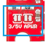
  • Level Select - Provides level selection between 3.3V and VSYS levels on VOUT. Default 3.3V

  • Expansion Header - The 70-pin Expansion header breaks out the functionality of the Intel Edison. This header also passes signals and power throughout the stack. These function much like an Arduino Shield.

Using the I2C Breakout Block

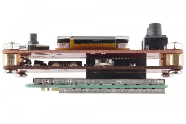
To use the I2C Breakout Block, attach an Intel Edison to the back of the board or add it to your current stack. Blocks can be stacked without hardware, but it leaves the expansion connectors unprotected from mechanical stress.

alt text

I2C Block Installed

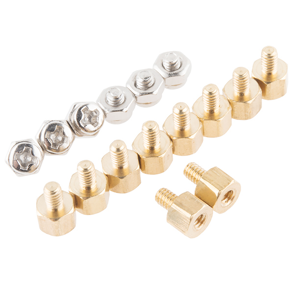
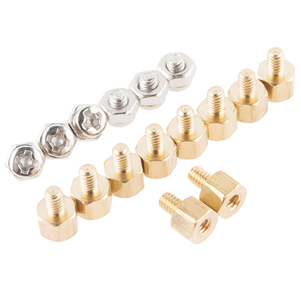
We have a nice Hardware Pack available that gives enough hardware to secure three blocks and an Edison.

alt text

Intel Edison Hardware Pack

NOTE: The I2C Breakout Block does not have console access or a power supply. It is recommended to use a console communication block in conjunction with this block like ones found in the General Guide to Sparkfun Blocks for Intel Edison.

Example

In our example, we will show how to connect and scan for the SparkFun RGB and Gesture Sensor. Solder a 4-pin section of our Right Angle Break Away Male Headers to the breakout board. Plug the board into the I2C Brekaout Block, and you’re done with the hardware connection.

alt text

SparkFun RGB and Gesture Sensor Installed

To find the I2C device in the console, type the following command. Note the I2C bus we will use is bus 1.

i2cdetect -y -r 1

We see that the device appears on address 0x39 as expected.

     0  1  2  3  4  5  6  7  8  9  a  b  c  d  e  f
00:          -- -- -- -- -- -- -- -- -- -- -- -- --
10: -- -- -- -- -- -- -- -- -- -- -- -- -- -- -- --
20: -- -- -- -- -- -- -- -- -- -- -- -- -- -- -- --
30: -- -- -- -- -- -- -- -- -- 39 -- -- -- -- -- --
40: -- -- -- -- -- -- -- -- -- -- -- -- -- -- -- --
50: -- -- -- -- -- -- -- -- -- -- -- -- -- -- -- --
60: -- -- -- -- -- -- -- -- -- -- -- -- -- -- -- --
70: -- -- -- -- -- -- -- --

To use the SparkFun RGB and Gesture Sensor in your project, you can modify the code from the RGB and Gesture Sensor Hookup Guide to run on your Edison. Using the Arduino IDE for Edison, the demo should work out of the box!

Using 5V Devices

There is a way to modify the I2C block to accept 5V logic. Cut the voltage select jumper, but do not re-connect to either VSYS or 3.3V. You will now need to supply your own 5V voltage (for your sensors) externally. You can solder a 5V supply to the center pad OR use the VOUT pin on the connector. Supplying 5V through the VOUT trace will allow you to plug sensors in without modification.

alt text

Resources and Going Further

Now that you have had a brief overview of the I2C Breakout Block, take a look at some of these other tutorials. These tutorials cover programming, Block stacking, and interfacing with the Intel® Edison ecosystems.

Edison General Topics:

Block Specific Topics:


learn.sparkfun.com |CC BY-SA 3.0 | SparkFun Electronics | Niwot, Colorado


BC118 BLE Mate 2 Hookup Guide

$
0
0

BC118 BLE Mate 2 Hookup Guide a learn.sparkfun.com tutorial

Available online at: http://sfe.io/t287

Introduction

SparkFun’s Bluetooth low energy (BLE) Mate 2 is a no-nonsense Bluetooth 4.0 (aka Bluetooth low energy or Bluetooth Smart) development board related to our Bluetooth Mate Silver and Bluetooth Mate Gold.

The BLE Mate 2

The BLE Mate 2 only supports Bluetooth 4.0; it won’t connect to older devices. It’s also worth noting that BLE does not support a Serial Port Protocol as older versions of Bluetooth did; that makes interoperability between BLE dongles, devices, and modules harder than with Bluetooth Classic.

As you can see, the BLE Mate 2 is a small board: 1.0" by 1.95" (25mm x 50mm). The six-pin header on the end opposite the module is a “host” serial pinout, the same as that on the FTDI Basic boards, which allows the BLE Mate 2 to be connected directly to any device with a matching header, such as the SparkFun Arduino Pro and Pro Mini. Coupled with the FTDI SmartBasic, you can even develop your code without having to swap cables! The board has built-in level translation, so it can be used with boards of higher voltage than the 3.3V default used by the BC118.

You’ll also notice that there are breakout holes available for all the pins on the BC118 module; we’ll cover the use of those in a later section.

Covered in this Tutorial:

  • Hardware hookup of the BLE Mate 2
  • BC118 functionality
  • BLE Mate 2 library and example code

Materials Used

  • Arduino Pro 5V - You could just as easily use the 3.3V version, or the Pro Mini, or (in fact) any board that supports serial communications.
  • BLE Mate 2 (natch) - Depending on what you want to do, you may need two of these. We’ll demonstrate an example connecting to another BLE Mate 2 as well as providing some application examples showing how to connect to an iPhone or an Android device.
  • FTDI SmartBasic - The SmartBasic was designed for just this application–to allow an Arduino to be programmed while allowing the hardware serial port to be selectively attached to another serial device. It’s not recommended that you use a software-controlled serial port for this application as the data flow from the BLE Mate 2 can easily overwhelm the buffer.
  • Snappable male header pins - You’ll need to add pins to the SmartBasic and the BLE Mate 2 (if you want to plug the BLE Mate 2 into a breadboard).
  • 6- and 8-pin female headers - at a minimum. You’ll want a 6-pin female for the BLE Mate and the SmartBasic and an 8-pin for the Pro.
  • Jumper wires - You really only need one of these, to connect the Arduino Pro to the OE line on the SmartBasic.

Recommended Reading

Before you go any further, you may want to review some of these other tutorials:
* Loading an Arduino Library - There is a library available for the BC118 module on the BLE Mate 2 github repository, and this tutorial will explain how to load it.
* Hexadecimal - A lot of the parameters used by the BC118 are in hexadecimal; brush up on what that means with this tutorial!
* Bluetooth Basics - Learn some of the basics of how Bluetooth works.

Hardware Overview

Let’s take a look at the BLE Mate 2 board.

Front

Top view of the board

The image above has the major parts of the BLE Mate 2 labeled. We’ll start with the front, since it’s more interesting. We’re just going to apply labels to things here; we’ll discuss their full use on the next page.

  1. 6-pin FTDI Basic compatible serial header - This header has the same pinout as that of an FTDI Basic board; it’s meant to connect to a client device such as an Arduino Pro. If you want to connect it to an FTDI Basic board, you’ll need to either make or buy a crossover adapter. We’ve provide two rows of pins to make multiple connections to these pins (e.g. to sniff the signals for troubleshooting) easier.
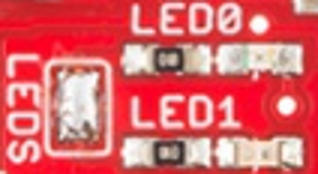
  2. LED0 and LED1 - These LEDs display information about the current state of the module. These LEDs reflect the logical state of the module, and a reset of the module may be needed before the settings take effect. More on that later.
  3. LEDs jumper - this jumper ships closed with solder; clear the jumper to disable the LEDs and save some current for low-power situations.
  4. INP jumper - this jumper connects the voltage input pin on the 6-pin header to the 3.3V regulator on the BLE Mate 2. It can be cleared to remove the regulator from the circuit and save current.
  5. REG jumper - clearing this jumper will break the connection between the output of the 3.3V regulator and the supply of the BC118 module.
  6. GPIO headers - All the pins on the BC118 are broken out to these pins, as are power and ground.

Back

Bottom view

The back is much simpler. You’ll note that all the pin labels are present on this side as well.

The one thing that is really worth pointing out from this side is the keepout at the top of the board. You can see that the ground plane only extends so far up the PCB; for best performance, you should try and keep that area free of any metal when embedding the BLE Mate 2 in a project. Failing to do so may result in interference or a loss of signal strength.

Hardware Connection

This page will cover both general hardware connection for the BLE Mate 2 as well as specific information for this tutorial.

6-pin Serial Header

Serial Header

The pinout on this header matches that of the FTDI Basic boards, so it can be used anywhere an FTDI basic can be. However, it’s probably not fast enough to do any kind of wireless bootloading.

  • DTR - Connected only to the other DTR pad. This pin can be connected to PIO5 to provide a DTR output to the client device; that signal will be at a voltage determined by the supply voltage of the BC118 module and so may not be adequate to drive the reset signal on an Arduino.
  • RXI - Data IN from the client device.
  • TDO - Data OUT from the BC118 device. Shifted up to the level on the VCC pin of this header.
  • VCC - Connected to the INP jumper (see below).
  • CTS - Connected only to the other CTS pad. Can be connected to PIO6 to provide an RTS signal to the BC118. That signal must not exceed the supply voltage of the BC118 module.
  • GND - Negative supply rail for the entire module.

GPIO Headers

GPIO Headers

There are two 0.1" (2.54mm) headers along the sides of the module. These pins are 0.9" (22.5mm) apart, so they’ll fit into a breadboard (although not a lot of space will be left outside the pins!)

The currently useful pins on the BC118 module are all broken out to these headers; I’ll go over what they do and what they can do. Here, I’ll talk about commands and configuration parameters on the next page, but they will be referenced below.

  • AIO2 - By default, this is an analog input, which can be read by sending the command “AIO 2” to the module. The module will respond with the voltage on this pin, in mV. If the “ACFG” parameter is “ON”, this pin will reflect the module’s state: HIGH if the module is connected or LOW if the module is not.
  • AIO1 - Default function is same as AIO2. If the “ACFG” parameter is “ON”, pulling this pin HIGH will enable transparent mode, causing data presented to the RX pin to be sent verbatim to any connected device.
  • AIO0 - Default function is same as AIO2. If “ACFG” is “ON”, this pin determines the module’s role at boot time. If the signal is HIGH, the module will boot into Central mode. If LOW, Peripheral mode.
  • P3 - GPIO3. Default is to either mirror from or mirror to another connected device. More on this later.
  • P4 - LED0 output.
  • P8 - By default, exit transparent mode. Can be configured as an IO pin for mirroring by setting the “GPIO” parameter to “OFF”
  • WK - Dependent upon the “WAKE” and “WLVL” parameters, this pin can be used to wake the device from hibernation.
  • VIN - This pin connects to the INP jumper. More on this below.
  • GND - Ground for the entire circuit.
  • P5 - When parameter “FCTR” is “ON”, this will be a CTS output from the BC118.
  • P6 - When parameter “FCTR” is “ON”, this will be an RTS input to the BC118.
  • P7 - GPIO7. See P3 above.
  • P11 - GPIO11. See P3 above.
  • P9 - LED1 output.
  • P10 - GPIO10. See P3 above.
  • P2 - Not currently enabled.
  • VDD - This pin ties directly to the supply rail of the BC118. It must be kept between 1.8V and 4.3V to avoid damage to the module.
  • GND - Ground for the entire circuit.

LEDs

LEDs

As mentioned on the previous page, LEDs 0 and 1 provide some easily accessible feedback on the current state of the module. Here’s a decoder ring for sorting out what they mean.

LED 0
Blue
LED 1
Red
Status
BLINKOFFScanning
OFFBLINKAdvertising
ONOFFConnected
Central
OFFONConnect
Peripheral
ONONIdle

Note: the LEDs will change to represent the current settings of the module when changing into scanning, advertising, or idle modes, but the module will not change state until the changes have been written to non-volatile memory and the module has been rebooted.

LEDS Jumper

This jumper disconnects the cathode side of the LEDs from the ground plane, disabling them and eliminating the few hundred microamps each one draws under normal circumstances. It ships closed by default.

INP and REG Jumpers

Default state of INP jumper

The INP jumper, pictured above, has four possible configurations but only three valid ones.

This is the default mode, as it ships. In this mode, the input voltage from the VCC pin on the 6-pin header and the VIN pin on the GPIO header is routed to the 3.3V regulator.

Regulator bypassed

In this mode, the input side of the regulator is disconnected from all pins, and the module’s supply is connected directly to the VIN pin and the VCC pin. In this situation, the voltage present on the input must be between 1.8V and 4.3V. That’s within the range of a single-cell LiPo battery, but not of a 5V target board!

It’s probably a good idea to clear the REG jumper at this point, too; putting a voltage on the output of the regulator but not on the input is liable to cause odd behavior.

The level shifting circuit is still active here, so if the data lines on your processor are at a higher voltage than the BC118 is being fed, communications will still work.

INP cleared

With no solder on the jumper, you’ve completely disconnected the module from the VCC and VIN pins entirely. You’ll need to provide power to the 3.3V pin on the GPIO header directly, with the same caveat as earlier regarding the voltage range.

Again, you should clear the REG jumper.

Finally, the fourth mode, which I’m not only going to include a picture of, it’s so inappropriate: a big old solder glob covering all three pads. Don’t do this. Seriously. It probably won’t do anything bad, but it’s not going to help your current consumption any, it may damage the regulator, and it will bypass the regulator. Just don’t do it.

BC118 Functionality

While you can just skip over this page and go straight to the code example and library documentation, it’s probably a good idea to at least skim it so you have some idea what’s going on under the hood.

Concepts

The BC118 realizes a custom BLE profile, so you’ll have to take that into account when developing an app for it. It also means you won’t be able to easily connect it to any other BLE modules other than another BC118.

Generally, when you change settings on the BC118, you need to write the settings to the onboard non-volatile memory and reset the module before they will take effect. When in doubt, write/reset–it’s the only way to be sure.

When the module boots in Central mode, it will immediately begin scanning and will scan until it reaches the timeout period (which may be never). To connect to a Peripheral devices, the BC118 must be in Central mode, and scanning. This makes programmatically detecting a successful connection difficult, as the acknowledgment of the connection is buried in a stream of detected devices. The BLE Mate 2 library takes care of that for you.

Communication With the Module

From the factory, the BC118 comes programmed to accept and transmit via the UART at 9600bps. There are two types of transactions the user can initiate with the module: Commands and setting/getting parameters.

The BC118 expects a carriage return (‘\r’) at the end of a command string; if you send a newline (‘\n’)(which is frequently a standard practice in serial communications; the Arduino println() function sends “\n\r” at the end of the transmission), that will cause a receive error.

All responses from the BC118 will be ended with “\n\r”, however, which makes that a good string pattern to recognize for detecting responses from the module. If the module was unable to parse the string between the last two carriage returns into a command, it will respond with “ERR\n\r”. At that point, the buffer is clear, and that fact can be a useful way to get to a known state for re-synchronizing user code with the buffer in the BC118.

Finally, regarding “transparent” mode: it’s possible to put the module into transparent mode, where it forwards data presented on the UART directly to the remote device, and forwards data received from the remote device directly to the UART. Unfortunately, once transparent mode has been activated, there’s no escape sequence that can be sent across the UART to return to data mode. GPIO8 and AIO1 can be used to exit transparent mode, but only if that function has been enabled (by setting the parameters GPIO and ACFG to ON, respectively). If those parameters haven’t been set, and transparent mode is entered, the only way out is to power cycle the module.

Useful Commands

Here’s a list of useful commands. For more information, you can refer to the Melody Smart User Manual.pdf) on the BlueCreation website.

Commands will be presented with the command first, then parameters to be passed afterwards in parentheses after the command, but the parentheses are not part of the command. Optional parameters will be in brackets. A pipe (‘|’) will be used to separate “choose one of these” parameters.

  • ADV (ON|OFF) - Turn advertising on or off. While this can be toggled without error in Central mode, it will have no effect.
  • AIO (0|1|2) - Report the analog voltage, in mV, on the respective analog input pin.
  • CON [(BT ADDRESS) (TYPE)] - Device must be in scan mode for this command to work! If parameter ACON is ‘1’, no parameter needs to be passed to this command and the module will connect to the first target that supports the Melody Smart protocol (i.e., another BC118 or an app you’ve written on a target device). Otherwise, BT ADDRESS should be the full 12-character hex address of the device to connect to, and type should be 0 for a public address (most common) or 1 for a private address.
  • DCN - Disconnect from remote device. Works in either peripheral or central mode.
  • HIB (timeout) - The “timeout” parameter should be an integer value between 1050 and 429496795, and represents the number of 1.024ms periods to elapse before the device emerges from hibernation. Restarting from hibernation is a clean reboot to stored settings.
  • GET (parameter) - Returns the value of (parameter), which can be any of the configuration parameters listed below.
  • RST - Resets the chip, loading all settings from non-volatile memory.
  • RTR - Restores all settings to factory defaults.
  • SCN (ON|OFF) - Enable or disable scanning.
  • SET (parameter)=(value) - No spaces around the equal sign! Set (parameter) to (value). Settings changed in this way will not persist through a reset or power cycle unless the WRT command is issued (see below).
  • SND (data) - Send a stream of binary data. At most, 20 characters can be sent when in Central mode and 125 in Peripheral mode, and the data must not contain a newline (‘\r’ or 0x0D) as that will trigger transmission.
  • STS - Return the status of the module.
  • VER - Return the version of Melody Smart on the current module, and the module’s 12-character Bluetooth address.
  • WRT - Save the current settings to non-volatile memory, causing them to persist after a reset or power cycle. Note that many settings require a WRT/RST cycle to actually take effect!

Parameters

In addition to the commands listed above, there are some parameters governing the behavior of the module which can be set or checked via the SET and GET commands mentioned above. Here are some of the most important ones.

  • ACFG=(ON|OFF) - When OFF, AIO pins are available as analog inputs. When ON, they can be used for control and reporting (see the “Hardware Connection” page for details).
  • ACON=(ON|OFF) - When ON, the module will connect to the first discovered compatible device. This may not be the device you want to connect to!
  • ADVC=(ON|OFF) - When ON, the device advertises constantly if not connected.
  • ADVP=(SLOW|FAST) - Advertising rate. Using SLOW will consume less power but make connecting to the module slower.
  • ADVT=(timeout) - How long the device will advertise after advertising begins (either at boot or due to the ADV command). Values range from 0 (forever) to 4260, and are integer representations of seconds.
  • CENT=(ON|OFF) - Enable or disable Central mode. Must WRT/RST to make this take effect!
  • CCON=(ON|OFF) - Should the device scan/advertise upon disconnection?
  • CONP=(max_conn_int) (min_conn_int) (latency) (timeout) - Settings this device will send to a Central connecting to it. (max_conn_int) must be greater than (min_conn_int), and both must be between 6 and 3200 and represent the connection interval in units of 1.25ms each. They represent the longest and shortest intervals between which the Central device will ask for data. (latency) is in terms of connection intervals and represents the connection slave latency, which is the number of periods the Peripheral will ignore the Central if it has no new data. Finally (timeout) is the connection supervision timeout, the longest period the Central device should wait before declaring the link lost. It’s an integer, in units of 10ms.

Arduino Library Example

If you haven’t done so yet, download the .zip file of the BLE Mate 2 GitHub repository and install the Arduino library from the “Arduino/libraries” sub directory.

The Example

There’s an example in the repository that can be accessed through the “Examples” menu in Arduino. It’ll show you how to use all the various functions in the library to connect two BLE Mate 2 boards. First, connect your hardware like so…

BLE Mate 2 hookup diagram

I’ve reproduced the code in its entirety below.

/****************************************************************
Code to demonstrate the use of the BC118 BLE module on the
BLE Mate 2 board by SparkFun electronics.


15 Nov 2014 - Mike Hord, SparkFun Electronics

Code developed in Arduino 1.0.6, on an Arduino Pro 5V, using a
SparkFun SmartBasic board to multiplex uploading and serial
output.
****************************************************************/

#include <SparkFun_BLEMate2.h>

// You can also create a SoftwareSerial port object and pass that to the
//  BLEMate2 constructor; I don't recommend that because it's very possible
//  for the amount of traffic coming from the BC118 to overwhelm the fairly
//  shallow buffer of the SoftwareSerial object.
BLEMate2 BTModu(&Serial);

// This boolean determines whether we're going to do a central or peripheral
//  example with this code.

boolean central = true;

void setup()
{
  pinMode(2, OUTPUT);    // Control for the SmartBasic. If you look at the
                         //  bottom of the sketch, you'll see that I've added
                         //  functions called "selectBLE()" and "selectPC()"
                         //  to make it a little more obvious when I switch
                         //  between serial devices.
  Serial.begin(9600);    // This is the BC118 default baud rate.
  selectBLE();           // Route serial data to the BC118.

  // Regarding function return values: most functions that interact with the
  //  BC118 will return BLEMate2::opResult values. The possible values here
  //  are:
  //  REMOTE_ERROR - No remote devices exist.
  //  INVALID_PARAM - You've called the function with an invalid parameter.
  //  TIMEOUT_ERROR - The BC118 failed to respond to the command in a timely
  //                   manner; timely is redefined for each command.
  //  MODULE_ERROR - The BC118 didn't like the command string it received.
  //                  This will probably only occur when you attempt to send
  //                  commands and parameters outside the built-ins.
  //  SUCCESS - What it says.

  // Reset is a blocking function which gives the BC118 a few seconds to reset.
  //  After a reset, the module will return to whatever settings are in
  //  non-volatile memory. One other *super* important thing it does is issue
  //  the "SCN OFF" command after the reset is completed. Why is this important?
  //  Because if the device is in central mode, it *will* be scanning on reset.
  //  No way to change that. The text traffic generated by the scanning will
  //  interfere with the firmware on the Arduino properly identifying response
  //  strings from the BC118.
  if (BTModu.reset() != BLEMate2::SUCCESS)
  {
    selectPC();
    Serial.println("Module reset error!");
    while (1);
  }

  // restore() resets the module to factory defaults; you'll need to perform
  //  a writeConfig() and reset() to make those settings take effect. We don't
  //  do that automatically because there may be things the user wants to
  //  change before committing the settings to non-volatile memory and
  //  resetting.
  if (BTModu.restore() != BLEMate2::SUCCESS)
  {
    selectPC();
    Serial.println("Module restore error!");
    while (1);
  }
  // writeConfig() stores the current settings in non-volatile memory, so they
  //  will be in place on the next reboot of the module. Note that some, but
  //  not all, settings changes require a reboot. It's probably in general best
  //  to write/reset when changing anything.
  if (BTModu.writeConfig() != BLEMate2::SUCCESS)
  {
    selectPC();
    Serial.println("Module write config error!");
    while (1);
  }
  // One more reset, to make the changes take effect.
  if (BTModu.reset() != BLEMate2::SUCCESS)
  {
    selectPC();
    Serial.println("Second module reset error!");
    while (1);
  }
  selectBLE();

  // NB!!!!!!!!!!!!! This write/reset thing is *really* important.
  //  The status command (STS) and the LEDs *will* lie to you and tell you that
  //  you are e.g. advertising or in central mode when in fact that is not the
  //  case and the module still needs to be reset before that is actually true.

  // Okay, now we're unquestionably set to default settings. That means we're
  //  set up as a peripheral device, advertising forever. You should be seeing
  //  a blinking red LED on the BLE Mate.

  // At this point the example branches. Down one branch, we'll explore what it
  //  means to go into central mode, find and connect to a BC118, send some
  //  data, and disconnect. Down the other, we'll sit around waiting for
  //  something (either another BC118 or a phone or something) to connect and
  //  send us some data.

  if (central)
  {
    setupCentralExample();
  }
  else
  {
    setupPeripheralExample();
  }
}

void loop()
{
  // Since I'm going to be reporting strings back over serial to the PC, I want
  //  to make sure that I'm (probably) not going to be looking away from the BLE
  //  device during a data receive period. I'll *guess* that, if more than 1000
  //  milliseconds has elapsed since my last receive, that I'm in a quiet zone
  //  and I can switch over to the PC to report what I've heard.
  static String fullBuffer = "";
  static long lastRXTime = millis();
  if (lastRXTime + 1000 < millis())
  {
    if (fullBuffer != "")
    {
      selectPC();
      Serial.println(fullBuffer);
      selectBLE();
      fullBuffer = "";
    }
  }
  static String inputBuffer;
  if (central)
  {
    doCentralExample(); // We're going to go to this function and never come
                        //  back, since we want to do the central connection
                        //  demo just once.
  }
  else
  {
    // This is the peripheral example code.

    // When a remote module connects to us, we'll start to see a bunch of stuff.
    //  Most of that is just overhead; we don't really care about it. All we
    //  *really* care about is data, and data looks like this:
    // RCV=20 char max msg\n\r

    // The state machine for capturing that can be pretty easy: when we've read
    //  in \n\r, check to see if the string began with "RCV=". If yes, do
    //  something. If no, discard it.
    while (Serial.available() > 0)
    {
      inputBuffer.concat((char)Serial.read());
      lastRXTime = millis();
    }

    // We'll probably see a lot of lines that end with \n\r- that's the default
    //  line ending for all the connect info messages, for instance. We can
    //  ignore all of them that don't start with "RCV=". Remember to clear your
    //  String object after you find \n\r!!!
    if (inputBuffer.endsWith("\n\r"))
    {
      if (inputBuffer.startsWith("RCV="))
      {
        inputBuffer.trim(); // Remove \n\r from end.
        inputBuffer.remove(0,4); // Remove RCV= from front.
        fullBuffer += inputBuffer;
        inputBuffer = "";
      }
      else
      {
        inputBuffer = "";
      }
    }
  }
}

void setupCentralExample()
{
  // We need to change some settings, first, to make this central mode thing
  //  work like we want.

  // When ACON is ON, the BC118 will connect to the first BC118 it discovers,
  //  whether you want it to or not. We'll disable that.
  BTModu.stdSetParam("ACON", "OFF");
  // When CCON is ON, the BC118 will immediately start doing something after
  //  it disconnects. In central mode, it immediately starts scanning, and
  //  in peripheral mode, it immediately starts advertising. We don't want it
  //  to scan without our permission, so let's disable that.
  BTModu.stdSetParam("CCON", "OFF");
  // Turn off advertising. You actually need to do this, or the presence of
  //  the advertising flag can confuse the firmware when the module is in
  //  central mode.
  BTModu.BLENoAdvertise();
  // Put the module in central mode.
  BTModu.BLECentral();
  // Store these changes.
  BTModu.writeConfig();
  // Reset the module. Write-reset is important here!!!!!!
  BTModu.reset();

  // The module is now configured to connect to another external device.
}

void doCentralExample()
{
  // We're going to tstart with an assumption of module error. That way, we
  //  can easily check against the result while we're iterating.
  BLEMate2::opResult result = BLEMate2::MODULE_ERROR;
  // This while loop will continue to scan the world for addresses until it
  //  finds some. Why? Why not?
  while(1)
  {
    selectBLE();
    result = BTModu.BLEScan(2);
    if (result == BLEMate2::SUCCESS)
    {
      selectPC();
      Serial.println("Success!");
      break;
    }
    else if (result == BLEMate2::REMOTE_ERROR)
    {
      selectPC();
      Serial.println("Remote error!");
    }
    else if (result == BLEMate2::MODULE_ERROR)
    {
      selectPC();
      Serial.println("Module error! Everybody panic!");
    }
  }

  byte numAddressesFound = BTModu.numAddresses();

  // BC118Address is where we'll store the index of the first BC118 device we
  //  find. We'll know it because the address will start with "20FABB". By
  //  starting at 10, we know when we've found something b/c it'll be 4 or less.
  byte BC118Address = 0;
  String address;

  selectPC();
  Serial.print("We found ");
  Serial.print(numAddressesFound);
  Serial.println(" BLE devices!");
  // We're going to iterate over numAddressesFound, print each address, and
  //  check to see if each one belongs to a BC118. The first BC118 we find,
  //  we'll connect to, but only after we report our address list.
  for (byte i = 0; i < numAddressesFound; i++)
  {
    BTModu.getAddress(i, address);
    Serial.println("Found address: " + address);
    if (address.startsWith("20FABB"))
    {
      BC118Address = i;
    }
  }
  selectBLE();
  BTModu.connect(address);
  BTModu.sendData("Hello world! I can see my house from here! Whee!");
  BTModu.disconnect();
  delay(500);
  selectPC();
  Serial.println("The End!");
  while(1);
}

// The default settings are good enough for the peripheral example; just to
//  be on the safe side, we'll check the amICentral() function and do a r/w/r
//  if we're in central mode instead of peripheral mode.
void setupPeripheralExample()
{
  boolean inCentralMode = false;
  // A word here on amCentral: amCentral's parameter is passed by reference, so
  //  the answer to the question "am I in central mode" is handed back as the
  //  value in the boolean passed to it when it is called. The reason for this
  //  is the allow the user to check the return value and determine if a module
  //  error occurred: should I trust the answer or is there something larger
  //  wrong than merely being in the wrong mode?
  BTModu.amCentral(inCentralMode);
  if (inCentralMode)
  {
    BTModu.BLEPeripheral();
    BTModu.BLEAdvertise();
  }

  // There are a few more advance settings we'll probably, but not definitely,
  //  want to tweak before we reset the device.

  // The CCON parameter will enable advertising immediately after a disconnect.
  BTModu.stdSetParam("CCON", "ON");
  // The ADVP parameter controls the advertising rate. Can be FAST or SLOW.
  BTModu.stdSetParam("ADVP", "FAST");
  // The ADVT parameter controls the timeout before advertising stops. Can be
  //  0 (for never) to 4260 (71min); integer value, in seconds.
  BTModu.stdSetParam("ADVT", "0");
  // The ADDR parameter controls the devices we'll allow to connect to us.
  //  All zeroes is "anyone".
  BTModu.stdSetParam("ADDR", "000000000000");

  BTModu.writeConfig();
  BTModu.reset();

  // We're set up to allow anything to connect to us now.
}

// Below this point are support functions for the SmartBasic. If you're not
//  using the SmartBasic, you can leave this part off.
void selectPC()
{
  Serial.flush();
  digitalWrite(2, LOW);
}

void selectBLE()
{
  Serial.flush();
  digitalWrite(2,HIGH);
}

TL;DR Summary of Use

  1. Make liberal use of the write() and reset() functions when changing settings.
  2. Software serial is likely to be overwhelmed by the data from the BC118, so don’t expect good results from it.
  3. Don’t forget that Serial writes/prints are non-blocking. The library functions are all blocking with timeouts, but if you multiplex the serial port you’ll need to add Serial.flush() after non-library uses of the serial port to avoid writing non-command strings to the BC118.
  4. The BC118 must be in scan mode to connect to a peripheral!

Resources and Going Further

Here’s some more information to move you beyond this tutorial.


learn.sparkfun.com |CC BY-SA 3.0 | SparkFun Electronics | Niwot, Colorado

LilyPad Simple Power Hookup Guide

$
0
0

LilyPad Simple Power Hookup Guide a learn.sparkfun.com tutorial

Available online at: http://sfe.io/t242

Overview

The LilyPad Simple Power is a basic power board that enables you to power your wearable circuit with a lipo battery. It also allows battery charging in the circuit via microUSB cable, and it provides a nice on/off switch for your project.

LilyPad Simple Power

The LilyPad Simple Power. Small and simple!

Being part of the LilyPad line of boards, you can wash this PCB even after it’s been sewn to a garment. Just remember to remove the battery first before doing any washing!

With this quick tutorial, you’ll learn how to get started with the Simple Power.

Suggested Reading

Please check out the following tutorials, if you aren’t familiar with any of the topics.

Hardware Overview

True to its name, the LilyPad Simple power is really simple! There’s only a few features you need to be aware of.

alt text

Battery JST Connector

The Simple Power is designed to work with 3.7V lipo batteries. In order to connect the battery to the board, there should be a female JST connector on the battery you would like to use. Check out a list of compatible batteries here.

microUSB Connector

This allows you to charge your battery via a computer USB port, using a microB USB cable.

Positive/Negative Terminals

These sew taps are the connection points from where the power to your circuit will flow. The positive terminal outputs 3.7V, and the negative terminal is the ground (GND) connection.

On/Off Switch

This switch enables and disables power to flow out of the LilyPad Simple board. When it is in the ‘on’ position, you can measure the battery voltage across the positive (+) and negative (-) terminals. When it is in the ‘off’ position, there is no measurable voltage output from the board.

Mounting Holes

These four holes spaced across the board are designed as additional anchoring sew taps. They are not conductive, and have no electrical functionality.

Hardware Hookup

In our example, we are going to assume you are powering a basic LilyPad LED. However, you can use the Simple Power to power a LilyPad Main board, or various other products.

One thing to note about the Simple Power- it is designed for e-textile applications, but you can solder to the board. Just keep in mind it’s going to take more solder and more heat to attach wires to the sew taps.

Basic Simple Power Circuit

Our example circuit using the Simple Power and a LilyPad LED.

Find the ‘+’ terminal on the Simple Power and run a stitch/wire to the ‘+’ sew tap on the LED (or whatever board you are powering). Then run a wire or stitch from the ‘-’ terminal on the Simple Power to the ‘-’ sew tap on the LED. If you are using conductive thread, make sure you don’t let the two lines touch! This will short out your battery, possibly short out your Simple Power, and you’ll have a bad time.

Once your boards are connected, plug in your battery, and flip the Simple Power switch to the ‘on’ position. Bask in that happy LED glow!

Charging the Battery

If your battery runs down, have no fear! Simply plug in a microUSB cable into your computer and also into the LilyPad Simple board, and have some patience. There’s a yellow LED that indicates when the board is charging the battery. The board may also get warm while charging, but this is totally normal. Charging times will vary depending on the capacity of the battery connected to the Simple Power.

Resources and Going Further

Going Further

Now that you know how to use the LilyPad Simple Power, you can start integrating it into your own projects. If you need to check out the design files for the board, you can find them in the GitHub repo. You can also dig into the datasheet for the MCP7383 charger IC here.

Additional Resources

If you have any feedback, please visit the comments or contact our technical support team at TechSupport@sparkfun.com.

Check out these additional resources for more information and other project ideas.


learn.sparkfun.com |CC BY-SA 3.0 | SparkFun Electronics | Niwot, Colorado

SparkFun Blocks for Intel® Edison - Base Block

$
0
0

SparkFun Blocks for Intel® Edison - Base Block a learn.sparkfun.com tutorial

Available online at: http://sfe.io/t280

Introduction

The Base Block is a great foundation to any Edison stack. The Base is useful for mounting an Edison as a file system on a host computer or accessing the console port. The Base Block provides the same functionality as the Intel® Edison and Mini Breakout board with the added capability of powering the Edison through the Console port, freeing the OTG port for device usage. Use this block to load new OS images or firmware.

alt text

Base Block

Suggested Reading

If you are unfamiliar with Blocks, take a look at the General Guide to Sparkfun Blocks for Intel Edison.

Other tutorials that may help you on your Edison adventure include:

Board Overview

alt text

Base Block Functional Diagram

  • USB OTG - The USB Micro AB port provides access to the Edison OTG port. This port is capable of providing power to an OTG device or power can be supplied to the Edison through this port.

  • Console - The Micro USB B port provides power and a console access port to an Intel Edison Stack. This Block supplies a voltage to the Edison and other Blocks through the VSYS line at 4V. This voltage may vary up to +/-0.1V depending on load.

  • Power Button - The power switch is connected to the “PWRBTN” line on the Edison. This give the user the ability to place an Edison in sleep or power down the module completely. This does not affect power to other Blocks in the stack.

  • Power LED - The power LED illuminates when power is present on VSYS. This can come from the Console Block, or any other powered Block in the stack.

  • Data LEDs - The Data LEDs help the user identify if the console is active. This is a feature commonly found on our FTDI breakout.

  • LED Jumpers - If power consumption is an issue, cut each jumper to disable LEDs

  • Expansion Header - The 70-pin Expansion header breaks out the functionality of the Intel Edison. This header also passes signals and power throughout the stack. These function much like an Arduino Shield.

Using the Base Block

To use the Base Block, attach an Intel Edison to the back of the board, or add it to your current stack. Blocks can be stacked without hardware, but it leaves the expansion connectors unprotected from mechanical stress.

alt text

Base Block Installed

We have a nice Hardware Pack available that gives enough hardware to secure three blocks and an Edison.

alt text

Intel Edison Hardware Pack

Connecting to the Console

Once you have connected your hardware, plug the Micro USB cable into the Block. If you do not have FTDI drivers currently installed, you’ll need to download and install them before using your Edison. Visit our tutorial for instructions on how to install the drivers. After you have ensured that the drivers are installed and your device is running, open your favorite terminal program and point it to the USB-serial connection. We have another tutorial to explain terminal programs and how to use them.

The standard Baud Rate is 115200bps.

Once a terminal is active you are ready to explore!

alt text

Using the OTG port

Intel has done a great job at making the OTG port functionality seamless. If you wish to access the Edison as a mass file storage device or network device, plug a USB Micro B cable into the OTG port from a host computer. The device should automatically appear.

alt text

You can also load new OS images to the Edison over the OTG port. See the Loading Debian Ubilinux on the Edison tutorial for more details.

To use a USB device on the Edison, use our USB OTG Cable and plug in your device. The Edison will supply the necessary power for small USB devices. To find your connected device enter the following command into a console session.

lsusb

This should list any available USB devices installed.

Using the Power Button

The power button on the Edison brings a unique feature commonly not found on single board computers. The power button behaves much like the power buttons on desktop and laptop computers.

  • While powered, Holding the power button for ~10 seconds will power down the Edison.
  • While un-powered, pressing the power button momentarily will reboot the Edison.
  • While powered, pressing the power button momentarily will place the Edison in sleep mode.
  • While in sleep mode, pressing the power button momentarily will wake the Edison.

Resources and Going Further

Now that you have had a brief overview of the Base Block, take a look at some of these other tutorials. These tutorials cover programming, Block stacking, and interfacing with the Intel Edison ecosystems.

Edison General Topics:

Block Specific Topics:


learn.sparkfun.com |CC BY-SA 3.0 | SparkFun Electronics | Niwot, Colorado

Insulation Techniques for e-Textiles

$
0
0

Insulation Techniques for e-Textiles a learn.sparkfun.com tutorial

Available online at: http://sfe.io/t309

Introduction

This tutorial introduces five different methods for insulating conductive thread traces in an e-textile project. All the materials used in these methods can be found at your local craft or hobby store and require no specialized tools.

Why Insulate?

Conductive thread acts like uninsulated wire, which makes it great for sewing components together, but once a project is finished, the movement of fabric can let some pieces of thread accidentally touch. When working with conductive thread, make sure to pay special attention to insulating any power and ground lines so that they don’t short out your battery. Insulating stitches, once a project is complete, adds protection from potential short circuits created by movement, folding, or contact with conductive surfaces, as well as adding an extra barrier during wear and tear or washing.

Suggested Reading

Before You Begin

Make sure your project is fully functioning and completed before doing any insulation techniques – most of these are permanent methods of covering your stitching, and it will be very difficult to do any adjusting after the paint/glue dries.

Project Prep

Use this checklist to make sure your project is ready to be insulated:

  • All knots are secured and tails are clipped short
  • No short circuits or crossing threads
  • Battery/Power is removed or turned off - never work on a project while it is powered!

Stretch Fabric Glue

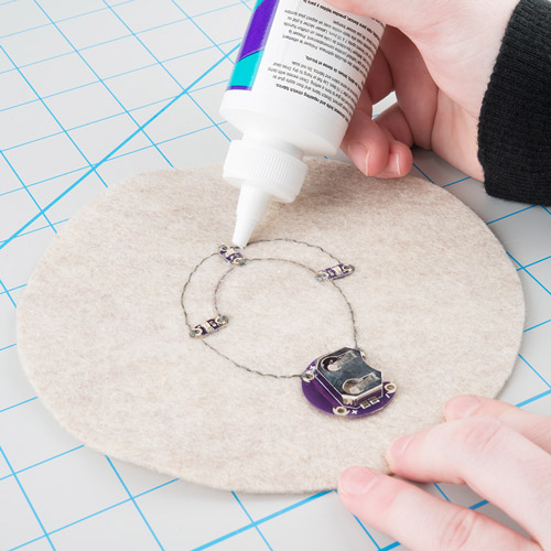
Using stretchy fabric glue is a great way to cover conductive thread without interfering too much with the flex of the fabric it is sewn into. This type of glue is typically used to fuse two pieces of fabric together, but can also provide a nice protective layer if applied on top of fabric.

This technique is one we learned from How To Get What You Want - a website full of tools and techniques around e-textiles and e-crafts.

Difficulty: Intermediate
Drying/Setting Time: Overnight
Mess Level: Moderate

Materials Needed:

  • Stretch fabric glue
  • Scrap paper
  • Paintbrush (optional) - to help spread the glue
  • Masking tape (optional) - use as a stencil for clean edges

alt text

Aleene’s Flexible Stretchable Fabric Glue is a common brand name and one we use a lot here in our e-textiles projects.

Instructions:

Apply a thin layer of glue over conductive thread directly from the squeeze bottle or using a paintbrush. Less is more with this technique - big globs of glue take longer to dry. Painting a few thin layers will give you better results than one thick layer.

alt text

* For extra neat lines try using masking tape around the sides of the thread to make a stencil, peel off when glue is completely dry.

Set aside to dry overnight. This glue is notoriously slow drying, so the longer you can let it set, the better. Depending on the thickness of the layer, it may remain tacky even after drying - a quick dusting or rub down of flour or baby powder will help.

Pros:

  • Flexible, stretchy seal over fabric and thread
  • Dries clear

Cons:

  • Takes practice to make even lines over thread
  • Long dry time
  • Glue remains shiny - flour/baby powder will also help with shine

Examples:

alt text

Check out Mika Satomi and Hannah Perner-Wilson’s Language Game project for a costume that uses this technique over conductive fabric traces. Learn more about using conductive fabric instead of thread in your project here.

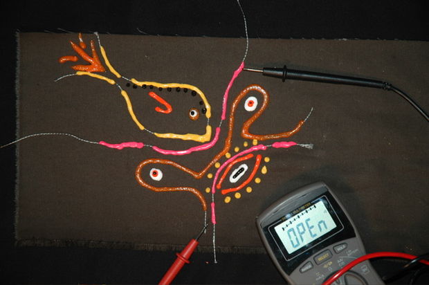
Fabric Paint

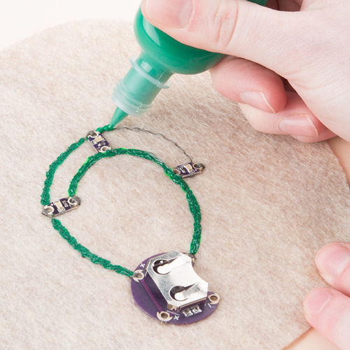
Fabric paint is a quick way to add insulation and style to a project. Using different colored paints to hide and decorate stitches can create a really unique look for the front of your project. We recommend using 3D or ‘Puff Paint’ because its thickness makes covering traces a lot quicker and the tubes have a fine tip that makes applying much easier than a paintbrush.

Difficulty: Easy/Intermediate
Drying/Setting Time: Overnight
Mess Level: Moderate

Materials Needed:

  • Fabric paint - 3D/Dimensional/Puff paint works great because it is commonly packaged in a squeeze tube or pen
  • Scrap paper
  • Paintbrush (optional) - to help spread the paint
  • Masking tape (optional) - use as a stencil for clean edges

alt text

Common Dimensional Paint Brands: Tulip Dimensional Paint, Scribbles Dimensional Fabric Paint, Puffy Paint. Look for these in the apparel crafting or paint section of your local craft store.

Instructions:

Have some scrap paper ready and do a few practice lines to get a feel for the flow of the paint. Make sure to shake the paint in case there was any separation of the pigment. When you are ready, carefully paint over the conductive thread, making sure to use a thin layer. You can always add a second layer if needed - avoid large clumps of paint as these tend to smear easy and take a long time to dry.

alt text

When your painting is complete, let sit overnight to dry.

Pros:

  • Decorative seal over thread
  • Lots of colors

Cons:

  • Takes practice to make even lines over thread
  • Long dry time - especially with thick paint
  • Squeeze tubes have a tendency to squirt out in large clumps - always have scrap paper handy when you first start using a tube

Examples:

alt text

Lynne Bruning wrote a quick tutorial on this technique that shows an interesting design with paint.

alt text

This LED Shoes Tutorial by Instructables member Carleyy makes great use of paint to hide the stitches and create a cool design.

Fabric Layer/Liner

Using a layer of fabric (or building your circuit underneath a garment’s lining) is an easy way to protect conductive thread and leave a soft backing if the project is going to be worn against skin. This is also good method for insulating the front of your circuit with fabric designs.

Difficulty: Easy
Drying/Setting Time: None
Mess Level: Minimal

Materials Needed:

  • Fabric
  • Scissors
  • Needle and non-conductive thread OR glue (fabric glue or hot glue gun)

Instructions:

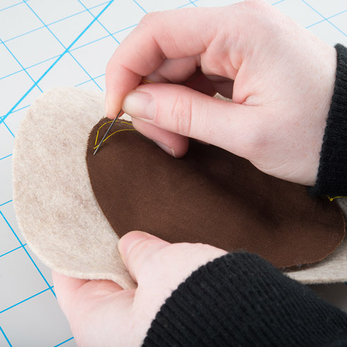
Cut a piece of fabric (or small pieces) to cover your circuit. Attach the fabric by sewing or using glue, being careful not to accidentally damage any of your stitches or components. Get creative with your designs if insulating the front of your project - appliqué, cut outs, and shapes can add interest as well as insulation.

alt text

Tips:

  • If using glue, be careful it doesn’t saturate through the top of the fabric.
  • When cover a large area, make sure to sew or glue at various places in the middle of the fabric, not just at the edges. This helps keep the fabric flush with the circuit and avoids any accidental folding underneath that could short circuit the thread.

Pros:

  • No exposed wet paint or glue to deal with
  • Great way to use scrap fabric from constructing your project

Cons:

  • Can get bulky depending on fabric choice
  • Sewing can be time intensive, depending on the complexity of your designs

Examples:

alt text

Our Twinkling Trick or Treat Bag project uses fabric designs to cover up components on the front of the bags.

Embroidery/Decorative Stitching

If you have a lot of patience (or a sewing machine), using embroidery to cover conductive thread traces can add a beautiful finishing touch to your project. Depending on your project size and fabric type, hand embroidery may be easier to do than fitting the project on a machine. This method also works well if you are insulating the front of a project. For just the interior, try a quicker method like interfacing or fabric layers.

Difficulty: Intermediate
Drying/Setting Time: None
Mess Level: Minimal

Materials Needed:

  • Embroidery Thread
  • Embroidery Needle
  • Scissors
  • Sewing Machine (optional)

Instructions:

Hand Stitching:

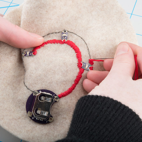
Carefully follow the line of conductive thread and cover using a satin stitch. Here’s a tutorial from Sublime Stitching on the satin stitch. You can also add additional embroidery around the conductive thread to incorporate it into a larger design. Get creative!

alt text

Machine Stitching:

If you project fits easily on a sewing machine, use a zig zag (or button hole) stitch on a small setting and sew over the conductive thread. Be careful not to sew over any components - they could get damaged by the needle, or more likely break your needle and get caught in the machine. Leave about an inch around any components and a long tail of thread to finish the stitching by hand.

Lynne Bruning published a tutorial on this technique that walks you through loading your project into a machine.

Tips:

  • Make sure the embroidery stitches are close together and completely cover the conductive thread - any gaps will expose the thread and leave more room for short circuits.

Pros:

  • No wet paint or glue to deal with
  • Creative stitching will completely camouflage your traces
  • Can insulate both front and back of stitching in one step

Cons:

  • Embroidery can be tedious work for beginners
  • Time intensive

Examples:

alt text

This embellished version of our E-Textile Mask project uses embroidery to add detail and cover up the conductive thread and LEDs.

Fusible Interfacing

Fusible interfacing is typically used to add some structure or strength to parts of garments such as necklines or buttonholes. We’ll be using interfacing to cover conductive thread traces in wearables projects.

Difficulty: Easy
Drying/Setting Time: None
Mess Level: Minimal

Materials Needed

  • Fusible Interfacing
  • Iron, Ironing Board
  • Parchment Paper (optional, to protect the iron from any adhesive ironed by mistake)
  • Scissors
  • Marker

Choosing Interfacing

Interfacing comes in many types, from iron-on to sewable, heavy duty to light weight. It can be found at most craft and hobby stores like JoAnn Fabrics, Michaels, Hobby Lobby, or fabric stores.

Most fusible interfacings will have adhesive on one side. The adhesive (bumpy side with small glue droplets) presses against the fabric and melts to it when ironed, leaving a soft backing on the lining of your fabric.

When you go to the store look for a fusible or iron-on web or interfacing - make sure that it is one-sided adhesive. Some stores sell a double sided iron-on product made for fusing two pieces of fabric together, we won’t need that. Some common brands are Heat'n Bond (sold in a package) and Pellon (sold on a bolt as cut by the yard).

alt text

Preparing Your Circuit

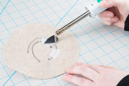
Place some interfacing (adhesive side down) over the back of your project.

alt text

Draw on the interfacing to mark out small pieces to cover the conductive thread. Be careful to leave some room around any components so the interfacing doesn’t cover them. The heat from the iron could be damaging to LilyPad pieces. Use a piece of parchment paper between the project and your iron to protect from any adhesive accidentally transferring to the iron.

Pros:

  • No wet paint or glue to deal with
  • Quickest method of insulation

Cons:

  • Some fabrics don’t respond well to heat and could melt when using the iron setting needed to activate the adhesive - always check your fabric or do a test on a scrap piece before ironing.
  • This method isn’t great for tiny projects, or ones with components very close

Examples:

alt text

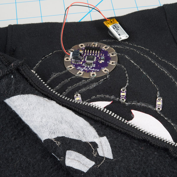
This LilyPad powered light up sweatshirt uses interfacing to protect the stitching and for the wearer’s comfort.

Resources and Going Further

Now that you know how to insulate your circuits, it’s time to get out there and make some projects! Need some inspiration? Check out these other great tutorials from SparkFun Electronics.

  • Twinkling Trick or Treat Bag - Make a light up goodie bag with conductive thread, LEDs, and the LilyTwinkle!
  • E-Textile Mask - Use LilyPad LEDs, a switched battery holder, and coin cell battery to make a fun light up mask for your next costume party.
  • My Drunk Kitchen Apron - A fun project that uses the LilyPad MP3 trigger. This apron will dispense helpful kitchen advice and humor from the host of My Drunk Kitchen, Hannah Harto!
  • Dungeons and Dragons Dice Gauntlet - Get your geek on with this wearable digital dice gauntlet.

learn.sparkfun.com |CC BY-SA 3.0 | SparkFun Electronics | Niwot, Colorado

Alphanumeric GPS Wall Clock

$
0
0

Alphanumeric GPS Wall Clock a learn.sparkfun.com tutorial

Available online at: http://sfe.io/t343

Introduction

The GPS Alphanumeric Clock is the clock you never have to set! Using UTC time and date we are able to parse out the local time using a Gregorian date calculator and some rules for US daylight savings time (DST). Calculating what day of the week it was on June 7th of 1983 is actually a bit of a challenge. Similarly, figuring out if we were or were not is DST for any given year was not as easy as you might think. This tutorial gives a good breakdown of how to calculate day of the week from any date and a simple way to make your clock set itself (assuming you know the date).

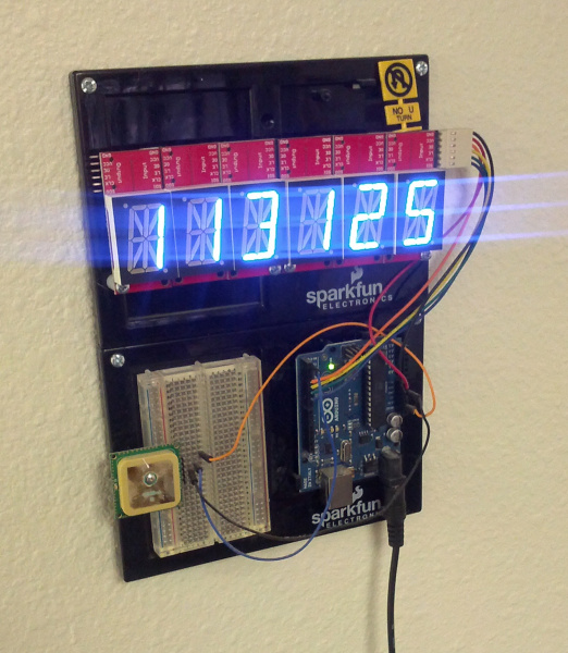
GPS wall clock

Suggested Reading

To better understand this project, you should be familiar with the following topics:

Hardware

It’s been awhile since we built the 12’ GPS wall clock. The GPS Alphanumeric Wall Clock is measurably smaller in size compared to the last one but a lot more sophisticated with its knowledge of local time.

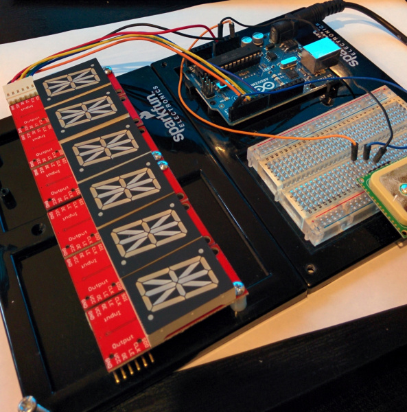
Wiring of GPS clock

This particular clock uses 6 of the 1” alphanumeric displays with controllers to create a 6 character display. While not as glitzy as EMSL’s awesome Alpha Clock Five, this setup allows us really simple control from an Arduino to scroll time, date, day, and some simple messages. These are controlled with a simple library using an Arduino Uno. A 5V walwart provides all the power for the displays and to power the Arduino. I originally used the Locosys LS20031 GPS receiver. This worked great for three years. Once my original DST code broke I decided to upgrade to the smaller, more sensitive GP635T GPS receiver.

If you’d like to build your own, we reccomend this parts list to get started:

Woes of DST

The hardware was pretty straightforward; the trick was stitching the code together. I originally built this project back in February of 2011 and I hard-coded the DST dates:

if(year == 2011) {
 if(month == 3 && day > 12) hour++; //DST begins March 13th
 else if(month > 3 && month < 11) hour++;
 else if(month == 11 && day < 6) hour++; //DST ends November 6th
 }

If the year was 2011, and the date was between March 12th and November 6th then add an hour for daylight savings time. What about 2012? Well, I’ll hard code those dates too (March 10, November 3). What about 2014? Forget 2014 - something will break before 2014 and I’ll just fix it then…

So 2014 rolls around, and there’s nothing more annoying than a clock on the wall that tells you the wrong time. This was my first lesson:

What you are building will last longer than you expect.

Perhaps it’s just me and my projects, but I always assume they’re going to break within a few days. When really, silicon and the code we load onto it will run for many tens of years in the right conditions; possibly longer than we will be alive.

Shoot. Where did I put that code? 2011 was before we started using github at SparkFun so I got to go digging through old hard drives. Yuck. Next lesson:

If a project doesn't have a publicly accessible repo it will break and no one will fix it.

I finally found the original code. I could have simply updated the hard coded values for the next 5-10 years, but what’s the fun in that?

Daylight Savings Rules

The history of daylight savings sucked up a few hours of my time, but setting that aside, the US government changed the rules (thanks guys!) back in 2007. We now go from -7 UTC (here in Boulder, CO) to -6 UTC between the 2nd Sunday in March and returns to -7 UTC on the 1st Sunday in November. From the date, we know when we’re in March or April, but how do we tell if we’re after the 2nd Sunday? We need to know the day of the week!

A Tuesday Next Year

Marty in Back To the Future went into the future to October 21, 2015. Holy smokes there’s already a countdown website. Neat! But how do we determine what day of the week October 21st will be? Luckily for us this is a wonderful problem for academics and math students to figure out. There is a reasonably straight forward formula to help us out:

//Devised by Tomohiko Sakamoto in 1993, it is accurate for any Gregorian date:
static int t[] = { 0, 3, 2, 5, 0, 3, 5, 1, 4, 6, 2, 4  };
year -= month < 3;
day_of_week = (year + year/4 - year/100 + year/400 + t[month-1] + day) % 7; //0 = Sunday

Given a day/month/year and these three lines of code, we can establish that October 21st, 2015 will be a Wednesday. Now that we know the day of the week, we can determine if we are in or out of DST.

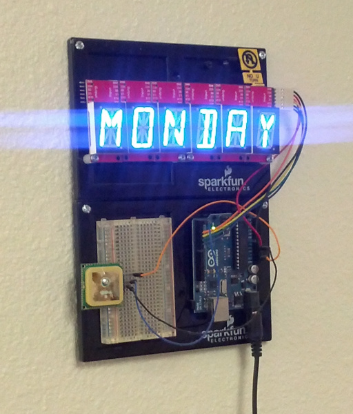
Clock showing monday

Lock Problems

Mikal Hart’s TinyGPS++ library is excellent to get you up and running quickly with GPS.

Google map of our roof.

The problem I found is that GPS clocks are often indoors, and, in the case of the SparkFun building, that makes it seriously difficult to get a GPS lock. We have lots of concrete, metal girders, and a large solar array that wreaks havoc with GPS signals (and pretty much all cellular carriers for that matter). TinyGPS++ reports the Time/Date only after you have a lock, so, when we moved the original GPS Wall Clock to our new building, I was somewhat mystified why it wasn’t working. Posting a ‘NOGPS’ debug statement to the display helped show that we almost never get sufficient enough satellites to allow TinyGPS to report time and date. Luckily, it doesn’t take a full lock to get date and time from GPS.

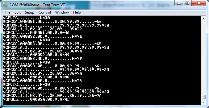
GPS time from NMEA sentences

If you look at the raw NMEA sentences above, you should be able to pick out ‘040054’ or 4:00.54 UTC. With only 1 satellite and a very bad view of the sky, we are able to grab time from GPS.

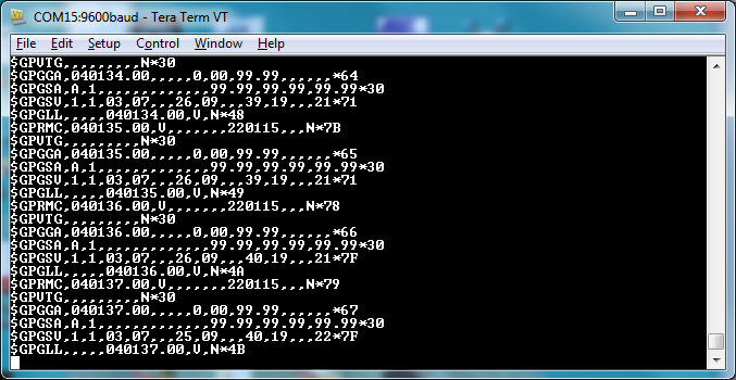
GPS date and time from NMEA sentences

After a few seconds we can see the date come in as well - ‘220115’ or January 22nd, 2015. The latest version of the Alphanumeric GPS Wall Clock uses a custom NMEA parser rather than relying on TinyGPS. It looks only for the availability of time and date, no GPS lock necessary. This allows us to display time in much harsher GPS environments.

Resources and Going Further

The final code combines all the pieces together to give us a GPS based clock that should last for many years to come. Or at least until the US government decides to change the rules again!

You can also find additional Arduino DST examples in the Daylight Savings Time Example repo.

Thanks for reading!


learn.sparkfun.com |CC BY-SA 3.0 | SparkFun Electronics | Niwot, Colorado

LilyTiny Plush Monster

$
0
0

LilyTiny Plush Monster a learn.sparkfun.com tutorial

Available online at: http://sfe.io/t340

Introduction

Craft a glowing-eyed stuffed monster while exploring the LilyTiny preprogrammed microcontroller. This is a project based on the Tiny Monster Activity created at MIT’s High-Low Tech Lab by Emily Lovell, Jie Qi, and Natalie Freed. While the original monster activity uses one LED, this project will use two (or more) to light up the monster’s eyes. We’ll learn how to hook up the LilyTiny board, prototype with alligator clips, and plan a conductive thread circuit on a three dimensional project.

This is a great project to try after you’ve done a couple e-sewing projects and before you are ready to start programming a full LilyPad Arduino project.

alt text

Suggested Reading

If you’ve never worked with e-textiles before, you may want to have a look at these other tutorials.

Materials and Tools

Let’s go over all of the things you’ll need to sew your project together:

alt text

You will also need:

  • Monster template - download and print the pdf template.
  • Felt - a 9x12 sheet of craft felt will make one monster.
  • Scissors
  • Hot glue gun
  • Cotton or embroidery thread
  • Fiber fill or something to stuff the monster with - such as scrap fabric
  • Optional - extra craft supplies to decorate (feathers, sequins, googly eyes, etc).

Step 1: Cut Out Template

Download and print the provided template. Align the template on your felt, and cut it out. We’re using an adaptation of the monster shape featured in Sew Electric, because it is an easy shape to cut out and sew and has plenty of room to attach all our LilyPad pieces. Feel free to use the template as a starting point, and design your own monster.

Right-click the image below, and choose “Save Link As” to download the template to your computer.

LilyTiny Monster Template

alt text

Rather than having two pieces that we then sew together, the template is one piece of felt that we’ll sew on and fold in half to finish. The connection point also serves as a bridge for all our conductive thread stitching to cross so that we can test the circuit flat before stuffing.

Step 2: Place Components

We’ll start building our monster by attaching the LilyTiny and battery holder. Take a look at the template and arrange the battery holder and LilyTiny so that their positive and negative pins face each other.

alt text

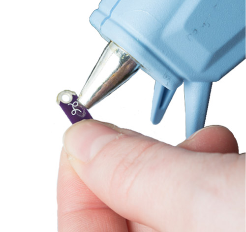
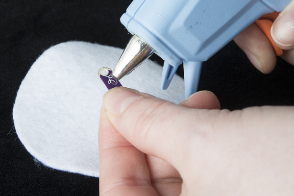
Then, use a little dab of hot glue on the back of the pieces to adhere to the fabric. Be careful not to fill any of the sewing holes with hot glue.

Don’t worry about attaching the LEDs just yet - we’ll be deciding where they go in a later step.

Step 3: Stitch Power and Ground Lines

Time to sew! Thread a needle with ~12 inches of conductive thread and tie a knot at the end.

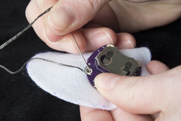
Start by looping 2-3 times through and around the positive pin of the battery holder closest to the LilyTiny.

alt text

Stitch across the fabric until you reach the positive pin on the LilyTiny. Loop 2-3 times and knot it there. Cut off any excess thread.

Repeat this process for the negative pin on the battery holder to connect it to the negative pin on the LilyTiny.

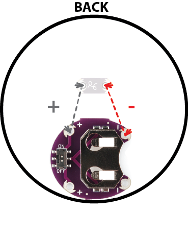
Color Key

alt text

Step 4: Exploring the LilyTiny Pins

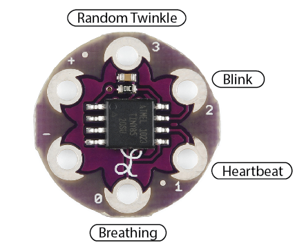
Next we will use alligator clips to temporarily connect an LED to the LilyTiny and decide which light pattern looks best for our monster. Each numbered pin is programmed with a different light effect.

alt text

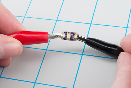
Use an alligator clip to attach the negative side of the LED to one of the negative pins on the battery holder. If the sewn one is too hard to grab with the clip, you can use the bottom negative pin. Make sure that the teeth of the clip are making good contact with the metal around the sewing holes.

alt text

Next, use another alligator clip to connect the positive end of the LED to one of the numbered pins on the LilyTiny. Once everything is hooked up, insert a coin cell battery into the battery holder, and turn the slide switch to the ON position. You should see a light pattern begin on the LED. To explore what the other LilyTiny pins do, carefully detach the end of the clip attached to the numbered hole, and move it to another one.

alt text

Step 5: Place LEDs

Now that we’ve decided what we want our LEDs to do, time to decide where they go.

Make sure to remove the battery from its holder and set aside before using the conductive thread. We’ll power the project up again once we’re done sewing the LEDs in place.

On the right side of the monster cut out, decide where the eyes should go. We’re using two LEDs for eyes, but feel free to use one for a cyclops design, or more for a different look. As you are planning the LED placement, make sure all the negative sides of the LEDs point downward, and the positive sides point upward.

alt text

Use a hot glue gun to fix the LEDs in place, making sure not to get any extra glue in the holes.

alt text

Step 6: Connect LEDs to LilyTiny

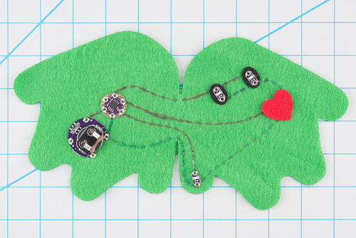
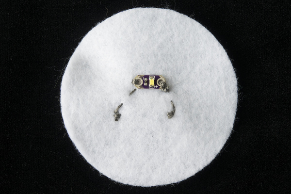
To make both LEDs light up together from one pin on the LilyTiny, we’ll be stitching them in a parallel circuit. Begin at the pin you chose on the LilyTiny, stitch along to the first LED, loop 2-3 times around the postive hole, then continue stitching until you reach the next one. Loop 2-3 times around, then tie a knot. To help plan where the stitches will go, you can use a marker to draw lines between the LEDs before sewing. If you don’t want to see the lines of conductive thread across the front of the monster, you can use a hidden stitch (blind stitch).

Color Key

alt text

We decided on the Random pattern programmed on pin 3.
Note how the stitching leaves enough room around the LilyTiny and other stitch lines so they don’t accidentally touch.

alt text

If we wanted to have a different pattern on each LED, the hook up would look similar to this.

Once all our stitching is finished, let’s add the battery back in and test the circuit. If everything is working, turn the switch to the OFF position before the final step.

alt text

This example monster shows multiple LilyTiny pins being used. The battery is in its holder for testing before moving on to the next step.

Step 7: Sew and Stuff Monster

Time to start the finishing touches on our monster. For e-textile projects with stitches on two sides that may touch, we’ll need some sort of insulation. Luckily fiber fill or fabric scraps will provide enough of a spacer that the conductive thread on the front and back won’t accidentally short circuit.

Make sure the battery is out of the project or switch is turned to OFF before this step.

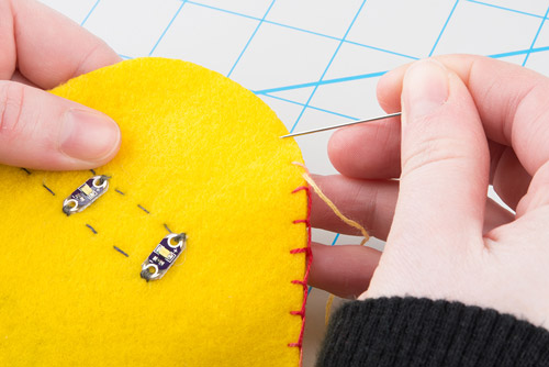
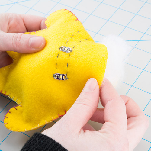
Fold the felt in half so that all the LilyPad components are on the outside. Using a non-conductive thread such as cotton, nylon, or some fancy embroidery stitching, sew along the edges of the felt - leave a 1-2" opening for stuffing.

alt text

alt text

Finishing Touches and Embellishments:

Once the monster is stuffed, close up the opening with a few more stitches, and start crafting a personality for it with eyes, facial features, or hair.

  • White felt circles over the LEDs make great eyeballs - the felt is thin enough that the LEDs will shine through.
  • If you want to hide your conductive thread stitching, try some fabric paint in a matching color or other decorations. This will also help protect from any short circuits if you accidentally set the monster down on a metal or conductive surface.
  • Faux fur or feathers make great crazy hair.

Here are some examples of finished monsters:

alt text

Resources and Going Further

Now that you’ve built the monster, you can try reprogramming the LilyTiny to create your own blinking effects.

Further Reading:


learn.sparkfun.com |CC BY-SA 3.0 | SparkFun Electronics | Niwot, Colorado

Light-Up Valentine Cards

$
0
0

Light-Up Valentine Cards a learn.sparkfun.com tutorial

Available online at: http://sfe.io/t339

Introduction

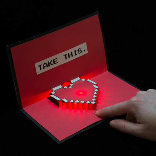
Light up your love with paper circuits this Valentine’s Day - no soldering required! This tutorial will guide you through how to create simple paper circuitry using only copper tape, a coin cell battery, a LilyPad Button Board, and an LED.

alt text

alt text

alt text

We’ve adapted some free pop up templates for use with electronics. We’ll be covering the electronics build in this tutorial and linking to the original project’s instructions for the pop up parts.

Why Aren’t We Soldering?

You may have seen Nick’s awesome Father’s Day Card tutorial and are wondering why this one is different? In classrooms or homes where supplies or budgets are limited, using tape and craft supplies helps keep complexity down. The drawback is that the connections aren’t as sturdy/permanent with tape vs solder. You can always use these templates and solder components to the copper tape if you have the supplies on hand.

Another option is to adhere components with a tiny square of Z-Axis Conductive Tape between the copper and component to provide a stronger connection than tape alone.

Suggested Reading

If you are brand new to working with electronics, here’s some helpful reading to check out:

Materials and Tools

Here is a list of all the materials and tools you’d need to follow along:

*A note on LEDs:

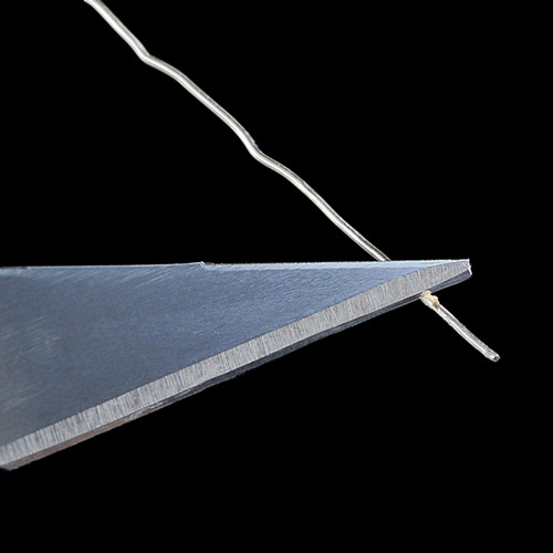
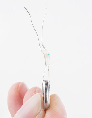
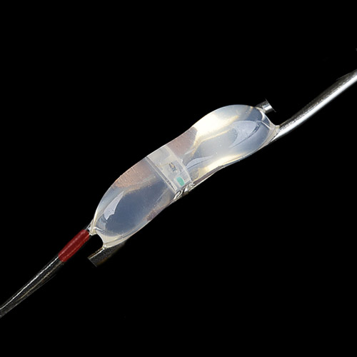
We recommend using the smallest LED you can find - 3mm work well because they don’t add too much bulk to your card when folded. For extra flair, try using cycling RGB LEDs. We’ve also found that cutting individual LEDs from a set of LED String Lights works well - you will have to use a hobby knife to scrape the coating off of the wires before using. We’ll cover that process later in the tutorial. Feel free to experiment with different LEDs to find what works best for your project.

Step 1: Print Templates

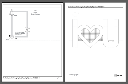
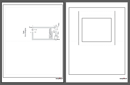
Right-click the images below, and choose “Save Link As” to download the templates to your computer. Each file has a circuit template page and a pop up template page.

Print your templates out on cardstock. If needed, adjust your printer’s margins, or choose ‘Fit to Page’ in the print settings. The card template is slightly smaller than the paper, so make sure to cut along the black border for the final card size.

Set the pop up pages aside for now. We’ll build our circuit first and then assemble the pop up once the electronics are all installed.

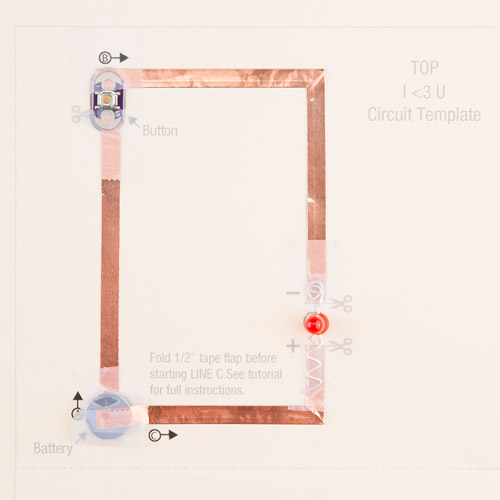
I <3 U Template - 2 pages

alt text

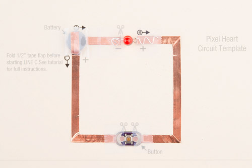
Pixel Heart Template - 2 pages

alt text

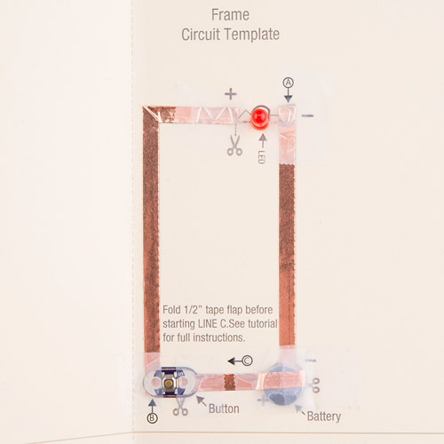
Frame Template - 2 pages

alt text

Step 2: Create Copper Traces

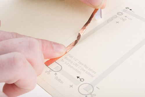
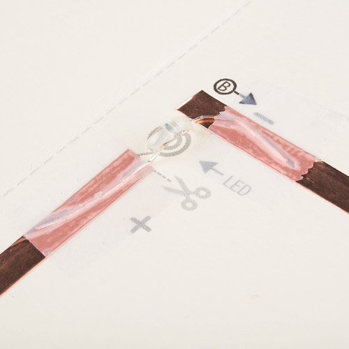
Time to create a path for our electricity with copper tape. We’ll be demonstrating with pictures from another paper circuit project, but the process is the same for these cards. Each has icons to help guide you in constructing the circuit.

alt text

Line A

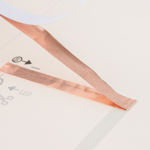
Take a look at the template and find the circle marked A. Peel away a few inches of the paper backing from the copper tape and stick down along the grey line.

alt text

Cut when you reach the scissors icon.

alt text

Line B

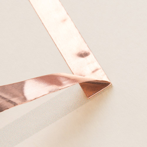
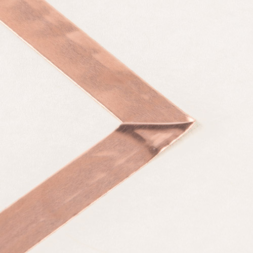
Next we’ll place tape along Line B which includes a corner. To keep a solid connection of copper around corners, we’ll be using a folding technique to press the tape into shape.

Start by sticking the copper tape down until you reach the corner, then fold the tape backward on itself. Use a fingernail or pen to give it a good crease at the edge.

alt text

Then carefully move the tape down around the corner - you should see the fold forming - and press down flat against the paper. The neatness of the fold doesn’t matter that much, it will be covered by your pop up in the end. Finally, cut the tape when you reach the scissors icon.

alt text

alt text

Line C

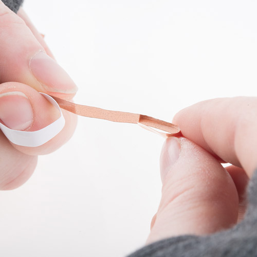
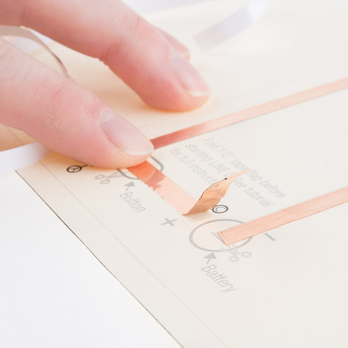
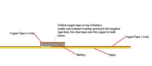
The last copper tape line will also form a battery holder. We’ll start by folding ½" of copper tape onto itself, sticking the adhesive sides together to form a flap.

alt text

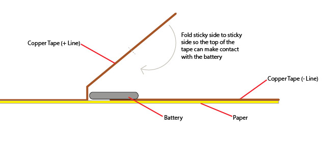
This allows the top of the copper to fold down over the coin cell battery - the positive side of the battery is the top and negative side is the bottom, which allows us to create a ‘battery sandwich’ with copper tape touching each side.

alt text

See the diagrams below to explore how this method works. We won’t be installing the battery until the end of our project, so set that aside for now. Fold the card in half along the dotted center line before moving onto the next step.

alt text

alt text

Step 3: Prepare and Place LED

Before prepping the LED, fold the card in half along the dotted line to save the hassle of trying to make a neat fold once there are components sticking up from the paper.

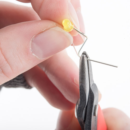
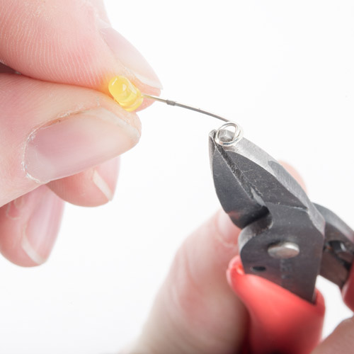
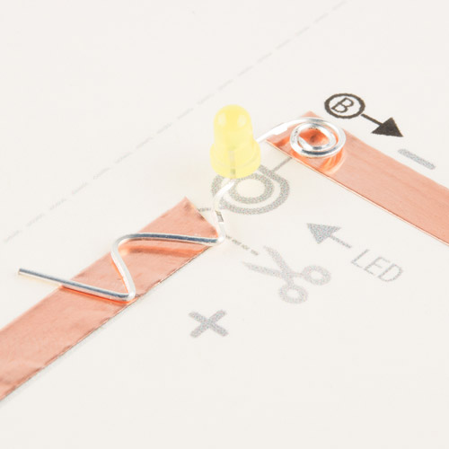
Now that our copper is in place, time to add the LED. Each template has an LED symbol which shows a shaped wire - we use this method to help us remember which side is positive and negative on the LED.

Here’s excerpt from our Light-emitting Diodes (LEDs) Tutorial about LED polarity:

“In electronics, polarity indicates whether a circuit component is symmetric or not. LEDs, being diodes, will only allow current to flow in one direction. And when there’s no current-flow, there’s no light. Luckily, this also means that you can’t break an LED by plugging it in backwards. Rather, it just won’t work. The positive side of the LED is called the “anode” and is marked by having a longer “lead,” or leg. The other, negative side of the LED is called the “cathode.”

alt text

Here are directions for bending a standard LED (as shown in the image above) to prepare it for our circuit.

Using pliers (or your finger), bend the longer leg of the LED flat. Then form the wire into a zig zag shape. Be careful not to break the wire by bending back and forth over the same joint too many times.

alt text

Next, bend the other leg flat and curl into a spiral. Use the end of the pliers to lightly grab the end of the wire and curl around the tool.

alt text

Once all shaping is complete, place the LED on a table or flat surface to make sure it sits flat and upright. If not, make any adjustments now.

alt text

Using LED String Lights

We’ve been experimenting with cutting up LED string lights, because they use tiny LEDs that are great for flat surfaces like greeting cards. Cut one LED off of the strip, making sure to leave ~½" of wire on either side. Then use a hobby knife to scrape away the coating from the wire to expose it. Make sure to scrape all around the wire, not just the top or bottom side, to ensure that you’ll have a good connection with the tape. Sandpaper will also work, if you don’t want to use a knife.

alt text

Each LED will have four wires coming from it - two positive and two negative because the LEDs are wired in parallel. It’s hard to see immediately which is which (they don’t have the handy longer/shorter trick like normal LEDs) - but we can quickly check them against a battery. Once we know which side is positive - mark the wire with a sharpie to help identify it. It’s okay to just leave the wires straight rather than shaping them like the other LED example.

alt text

If you have super eyesight - you can check for a green marking on the LED, this is the negative side.

alt text

This picture shows an LED from a string light prepped by identifying and marking the positive wire and trimming the extra wires so that they don’t accidentally short circuit each other.

Tape Down LED

Regardless of which LED type is going into the card, line up the positive lead with the copper tape marked + and the negative with -. Use clear tape over it to hold down to the copper.

alt text

Step 4: Attach Button

alt text

Next, we’ll place the LilyPad button over the oval icon on the template facing up. It doesn’t matter which side touches postive and negative. Make sure the conductive pads on the bottom of the button touch the copper tape, then tape down the ends with clear tape. Be careful not to tape directly over the push part of the button, or it may interfere with the ability to press it. You can also use a LilyPad switch instead of a button - the installation is the same.

alt text

Step 5: Insert Battery

Once all the components are installed, it’s time to test our circuit by adding a battery. Carefully slip the battery underneath the copper tape flap we made earlier, and center it inside the circle icon. Make sure the positive side of the battery (top, marked with the battery model and +) is facing up. Press the copper over the battery, and tape with clear tape.

alt text

Now, press the button, and the LED should light up!

alt text

Troubleshooting

  • Check the tape connections - use your nails or a pencil to make sure the tape is firmly adhering the components to the copper tape.
  • Check the battery - make sure it is sandwiched firmly between the top and bottom copper tape lines and that the top copper is not accidentally touching the bottom of the battery.
  • Check the wires of the LED - double check that they weren’t accidentally broken while bending them into shapes with pliers.

Here are what the finished circuits should look like:

alt text

alt text

alt text

Step 6: Prepare Pop Up

Time to cut out our pop up pieces. Click the links below to visit the pop up card’s website for full instructions on assembling.

I <3 U Instructions

Note: Glue a piece of vellum or parchment paper to the back of the heart outline before you fold the pop up to make it easier to attach.

The original project is in Korean, so we’ve included a tutorial we found a video on youtube showing you the process.

Pixel Heart Instructions

Note: This card can be tricky to pop up since there are so many small cuts. We’ve found using a pencil or thin marker to pull up the folds one at a time from the bottom of the heart up to the top makes it a little easier.

Frame Instructions

Note: Follow the folding instructions from the Window card in our Christmas Pop Up card tutorial. Use a piece of parchment paper or vellum behind the frame to create a base to attach stickers or cut outs, or draw on with markers. We chose a pet lovers theme, but feel free to create your own unique scene.

alt text

Step 7: Assemble and Admire

When your pop ups are constructed and ready to light, carefully place them over your copper tape circuit. Glue or tape the corners down to adhere to the backing. Gently fold down the pop up to close the card.

Finally, use a marker or stickers to indicate where the button should be pressed.

Add any extra decorations to make the card extra special. For Zelda fans, adding a “It’s dangerous to go alone! Take this.” screen shot to the outside of the pixel heart card adds a nice geeky touch - an idea we got from Instructables user Fungus Amungus’s version of this pop up card design.

alt text

alt text

Resources and Going Further

Things to try:

  • Try these techniques with other pop up designs or create your own - can you figure out how to adapt the copper tape path to fit your card choice?
  • Get crafty with stickers, paint, or markers after you’ve built your card to customize it even more.

Further Reading:


learn.sparkfun.com |CC BY-SA 3.0 | SparkFun Electronics | Niwot, Colorado


Hacker in Residence: The Harmonic Skew Zoetrope

$
0
0

Hacker in Residence: The Harmonic Skew Zoetrope a learn.sparkfun.com tutorial

Available online at: http://sfe.io/t330

Introduction

There are many things in our world that appear constant but are actually flickering at frequencies faster than we can easily perceive. Whether it’s the rapid sequence video frames, the alternating current in our power outlets (and the resultant imperceptible blinking of our light fixtures), or even the compression and rarefaction of the air molecules that make up sound waves, these frequencies are all around us.

Sometimes the curtain is pulled back and we can see evidence of these frequencies. The wagon wheel effect is one such case. Sometimes, these artifacts are undesirable (like banding in video of a screen), but other times they are the underlying mechanic of a device’s functionality (like a zoetrope).

The Harmonic Skew Zoetrope uses moving subject matter and scanning lines of light to create the experience of visual distortion somewhat similar to slit scan photography, but without the mediation of a screen.

-Hacker in Residence, Jesse Harding

Suggested Reading

Tools and Materials

Here is a list of the tools and materials used in this project. If you would like to replicate this project on your own, you may need to search for the right combination of materials.

  • Motor
  • Eccentric Roller
  • Bearing
  • Tension Springs
  • Spinning Mirror (with motor)
  • Laser Diode (with cylindrical lens)
  • Adjustable Laser Diode Mount
  • Power Supplies
  • Speed Control (potentiometer or microcontroller)

Hardware Assembly

Let’s take a look at some of the parts that make up the Harmonic Skew Zoetrope. But first, a public service announcement…

Traveling with Electronic Components

alt text

When you travel by plane with loose electronic components, be ready to answer any and all questions the TSA may have for you. Its best to keep that stuff at the top of your bag so that they don’t have to rummage around when they inevitably search your stuff. Try to stay pleasant, and try to be descriptive but not overly technical.

Eccentric Roller Assembly

The main motor is mounted with the shaft pointing up so that we can make an object oscillate in a horizontal plane. Mounted to the shaft of the motor is a piece of aluminum with the mounting hole off-center (essentially like a vibration motor). This piece of aluminum will roll inside the bore of a ball bearing, the outside of which will be mounted to a platform that will be kept from rotating by tension springs on the corners.

alt text

Depending on the size of motor and platform, a counterweight may be required to mitigate vibration.

alt text

Testing the motor for current draw and vibration

Laser & Spinning Mirror Assembly

The cylindrical lens will bend the laser light in just one dimension, turning a point of light into a line of light. This allows us to scan the object so that the top and bottom of the object are illuminated at different points in time, but all points at the same height are illuminated at the same time.

alt text

I chose to use a dodecagonal mirror (12 sides) to reflect the laser light over approximately 60 degrees. More sides will decrease the amount of area over which the laser will scan. If the laser is scanning a larger area than the object, there will be more time that the object is not illuminated, which I wanted to avoid.

Here at SparkFun, we 3D printed a dodecagonal prism shape, hot glued mirrors onto each face, and attached it to a motor.

Once the spinning mirror is mounted, the laser can be mounted so that it is reflected toward the object. The adjustable mount allows you to fine tune this position. The closer you get the laser to the mirror, the larger the area illuminated by the scanning laser.

The speed of the oscillation of the object needs to be at or near a harmonic of the laser scan frequency (which is equal to 12 times the RPM of the motor, due to the number of sides). To match these frequencies, I used a potentiometer to vary the speed of the motor that spins the mirror, but you could also use an Arduino to read and control the speeds of both motors.

Results

IT WORKED!!! :)

I tested the Harmonic Skew Zoetrope with several objects: a piece of wood, a baby doll head, and finally a miniature skull.

The choice of a skull as the object to be distorted is a nod to Hans Holbein’s painting from 1533, The Ambassadors.

THANK YOU!

I want to thank everyone at SparkFun for being so helpful, specifically Toni Klopfenstein, Evan Spitler, Casey Kuhns, Mike Grusin, Byron Jacquot, Jeff Branson, and Nathan Seidle! You guys were great!!!

Thank You Video

Resources and Going Further

We hope you enjoyed this project tutorial. For more exciting laser fun, check out these other projects:


learn.sparkfun.com |CC BY-SA 3.0 | SparkFun Electronics | Niwot, Colorado

SparkFun Inventor's Kit for RedBot

$
0
0

SparkFun Inventor's Kit for RedBot a learn.sparkfun.com tutorial

Available online at: http://sfe.io/t181

Introduction

RedBot Angle View

The SparkFun RedBot is a great way to get your feet wet in the world of robotics. However, once you have assembled your RedBot, you may be at a loss as to where to go from there. Enter: the SparkFun Inventor’s Kit for RedBot, or the SIK for RedBot for short. This guide will go through nine different experiments, ranging from learning how to drive your RedBot to using an accelerometer to trigger your RedBot to move. Once you’ve mastered each experiment, you can take what you’ve learned in this guide and apply it to creating your own robot platform.

Experiment List:

Here is a breakdown of each experiment presented in this tutorial. Click on the link to jump to that section, or continue reading to get started with experiment 1.

  1. Software Install and Basic Test
  2. Drive Forward
  3. Turning
  4. Push to Start & Making Sounds
  5. Bumpers
  6. Line Following with IR Sensors
  7. Encoder
  8. Accelerometer
  9. Remote Control

Required Materials

In order to follow along with these experiments, you’ll need to make sure you have the following materials first.

Extra Supplies Needed

Suggested Reading

If you still need to assemble your RedBot, visit our RedBot Assembly Guide, for detailed instructions.Please note that are a couple of versions of the assmebly guide, for older version of the RedBot Kit, please see this assembly guide.

Already put together the RedBot? Great! It’s a good idea to double-check the wiring. If you hooked up the RedBot differently, you can either change the example code to reflect your changes or rewire you bot as per the assembly guide.

You will also need to learn a little more about the RedBot and sensors that comes along in the RedBot Inventor's Kit Guide. Please visit our Getting Started with the RedBot.

Before you go any further, you should probably make certain that you’re familiar with these other topics:

  • What is an Arduino? - Since the RedBot is based off the Arduino platform, it’s a good idea to understand what that means.
  • Installing the Arduino IDE - If you don’t have the Arduino software installed, this guide will help you out.
  • Installing an Arduino Library - To get the most out of the RedBot, you’ll want to install our RedBot library. This tutorial will show you how to install any library.
  • Accelerometer basics - One of the core sensors for the RedBot is an accelerometer. To find out more about accelerometers, check out this guide.
  • Analog to digital conversion - Many useful sensors for the RedBot will be analog. This guide will help you interface with them and make the most of the data you get back.
  • Pulse width modulation (PWM) - The RedBot includes two headers with PWM signals, and uses PWM to control the speed of the motors. It’s probably a good idea to be familiar with the concept.
  • I2C - The RedBot Accelerometer, which ships with the RedBot kit, uses I2C to communicate with the RedBot. While the accelerometer is accessible through the library with no knowledge of I2C required, if you want to get more out of it, you can check out this tutorial.

RedBot Library Quick Reference

We have written our own library to simplify the programming and interface to the RedBot motors, encoders, sensors, and other peripherals. Here is a quick summary / overview of the RedBot Library, classes, methods, and variables.

RedBotMotors class

RedBotMotors motors;– this creates an instance of the RedBotMotors class. This can only be instantiated once in your code. This allows you to control the motors with simple methods such as:

  • .drive(motorPower)– this method drives the right side CW and the left side CCW for positive values of motorPower (i.e. drives the RedBot forward), and it does the reverse for negative values of motorPower.
  • .pivot(motorPower)– this method spins the entire RedBot CW for positive values of motorPower and CCW for negative values of motorPower.
  • .coast()– stops the motors and allows the RedBot to coast to a stop.
  • .brake()– applies the brakes using the H-Bridge by shorting out both of the motors. Forces the motors to come to an abrupt stop.
  • .leftMotor(motorPower)– controls the leftMotor independantly. Positive values of motorPower spin the motor CW, and negative values spin the motor CCW.
  • .leftBrake(motorPower)– applies the brakes the leftMotor.
  • .leftCoast(motorPower)– stops the leftMotor allowing it to coast to a stop.
  • .rightMotor(motorPower)– controls the rightMotor independantly. Positive values of motorPower spin the motor CW, and negative values spin the motor CCW.
  • .rightBrake(motorPower)– applies the brakes the rightMotor.
  • .rightCoast(motorPower)– stops the rightMotor allowing it to coast to a stop.

Advanced

If you wish to control the motors independently, the following are the control pins for the left and right motors:

leftMotor_controlPin1 = 2
leftMotor_controlPin2 = 4
leftMotor_motorPwrPin = 5

rightMotor_controlPin1 = 7
rightMotor_controlPin2 = 8
rightMotor_motorPwrPin = 6

The RedBot uses the Toshiba TB6612FNG H-Bridge Motor Driver. The full datasheet is available here.

RedBotEncoder class

RedBotEncoder encoder(leftEncoder, rightEncoder);– this creates a RedBotEncoder object with the left encoder connected to pin leftEncoder and the right encoder connected to pin rightEncoder. This can only be instantiated once in your code.

  • .clearEnc(LEFT\RIGHT\BOTH)– clears the counter variable for either the LEFT, RIGHT, or BOTH encoders. The labels LEFT, RIGHT, and BOTH are specific types defined in this class.

  • .getTicks(LEFT\RIGHT)– returns a long integer value representing the number of encoder ticks (counts) for either the LEFT or the RIGHT encoder.

RedBotButton class

RedBotButton button();– Creates an instance of the RedBotButton class on the RedBot. Because the button is hardwired on the RedBot board to pin 12, this initialization is handled inside the library code. This can only be instantiated once in your code.

  • .read()– returns a boolean value representing the status of the button.

RedBotSensor class

RedBotSensor sensorA(pinNum);– this creates a RedBotSensor object connected to the port (pin) on the RedBot Mainboard. This is primarily used for the line-following sensors, but can be used with any analog sensor. This class can only be instantiated for as many sensors as you have on your RedBot.

  • .read()– returns an integer value scales from 0 to 255 for the analog voltage read by the sensor. 0 represents 0V and 255 represents 5V.

  • .setBGLevel()– reads the value of the sensor in it’s ‘nominal’ position. This value is stored as the ‘background’ level.

  • .setDetectLevel()– reads the value of the sensor in it’s ‘detect’ position. This value is stored as the threshold for a ‘detect’ level.

  • .check()– returns a boolean value that TRUE if the measured sensor value is greater than ¼ of the difference between the background and the detect levels. Note: This method only works if you have set both the BGLevel and the DetectLevel.

RedBotBumper class

RedBotBumper bumperA(pinNum);– Creates an instance of RedBotBumper object connected to the port (pin) on the RedBot Mainboard. While the RedBotBumper is designed for use with the whisker / bumper switches on the RedBot, it can be used with any digital sensor or switch. This class can only be instantiated for as many digital sensors (bumpers) as you have on your RedBot.

  • .read()– returns a boolean value for the state of the bumper. It returns TRUE when the bumper switch is closed or connected to GND.

RedBotAccel class

RedBotAccel accel();– Creates an instance of the RedBotAccel object. The RedBot accelerometer uses I2C for communication. Because of this, it needs to be connected to A4/A5 on the RedBot Mainboard. This can only be instantiated once in your code.

  • .read()– this reads the current values of the accelerometer and stores it into local variables in the library. It does not return any values.

  • .x– is the raw X-axis accelerometer value read using the .read() method. In general, these values vary from -16000 to +16000. The X-axis is aligned with the FWD/REV direction of the RedBot.

  • .y– is the raw Y-axis accelerometer value read using the .read() method. In general, these values vary from -16000 to +16000. The Y-axis is aligned with the lateral or RIGHT/LEFT direction of the RedBot.

  • .z– is the raw Z-axis accelerometer value read using the .read() method. In general, these values vary from -16000 to +16000. The Y-axis is aligned with the UP/DOWN direction of the RedBot.

  • .angleXZ– is a floating point value for the calculated angle between the X and Z axes of the accelerometer. It calculates the arc tangent between the raw X and raw Z values. On the RedBot, this is the forward / backward tilt.

  • .angleYZ– is a floating point value for the calculated angle between the Y and Z axes of the accelerometer. It calculates the arc tangent between the raw Y and raw Z values. On the RedBot, this is the side to side tilt.

  • .angleXY– is a floating point value for the calculated angle between the X and Y axes of the accelerometer. It calculates the arc tangent between the raw X and raw Y values.

RedBotSoftwareSerial class

RedBotSoftwareSerial xBeeRadio();– Creates an instance of the RedBotSoftwareSerial object. This library uses a lot of code from the standard Arduino SoftwareSerial library. The RedBot Mainboard uses pins A0 (14) and A1 (15) for TX and RX when switched to SW_SERIAL.

  • .begin(baudRate)– opens up the serial communication on the SW_SERIAL TX and RX lines of the RedBot Mainboard at the baudRate. Acceptable baud rates include: 300, 1200, 2400, 4800, 9600, 19200, 28800, 38400, 57600, 115200.

  • .write()– writes a single bye of data to the software serial port.

  • .read()– returns a single byte from the software serial port.
  • .available()– returns an integer value representing the number of bytes (characters) available for reading from a software serial port.

Experiment 1: Software Install and Basic Test

Install Arduino IDE

In order to get your RedBot up and running, you’ll first need to download the newest version of the Arduino software from www.arduino.cc. This software, known as the Arduino IDE (Integrated Development Environment), will allow you to program the board to do exactly what you want. It’s like a word processor for writing programs. Please visit our Installing Arduino IDE tutorial for step-by-step directions on installing the Arduino IDE.

Connect your RedBot to your computer

Use a USB miniB cable to connect the RedBot to one of your computer’s USB inputs. Make sure you have the four AA batteries in the battery holder.

Install FTDI drivers

Depending on your computer’s operating system, you will need to follow specific instructions. Please go to How to Install FTDI Drivers for specific instructions on how to install the FTDI drivers onto your RedBot.

Install the RedBot library

A library in Arduino is a set of files containing pre-written code that simplifies instructions and commands to perform certain tasks. We have written a specific library for the RedBot. Make sure you install the RedBot library. You will need it for all the example code. Click the link below to download it.

Copy/Move the RedBot folder to the libraries folder into your Arduino Documents folder. If you need a refresher on how to install an Arduino library, please see our library tutorial.

Example Code

Included in the library are a set of examples for the 9 RedBot Experiments. Click on File –> Examples –> RedBot –> RedBot_Experiments, you should see a list of the 9 Examples we have created.

alt text

If you need to find the example code separately, click the link below

You can also find the RedBot Kit Experiments example code on the RedBot Github page. To download all the code, click the “Download ZIP” button on the right-hand side of the page.

Open the downloaded ZIP file and copy the “RedBot_Experiments” folder to your Arduino sketchbook / documents folder.

Open the Arduino IDE and select board:

Open the Arduino IDE software on your computer. This step is to set your IDE to identify your RedBot. You will want to select the board, Arduino Uno. To do this, go to Tools > Board > Arduino Uno.

Arduino board selection

Select your Serial Port

Window users: Select the serial port for the RedBot from the Tools > Serial Port menu. This is likely to be COM3 or higher (COM1 and COM2 are usually reserved for other internal devices). To check, disconnect your RedBot and re-open the menu; the entry that disappears is the one for the RedBot. Reconnect the board, and select that serial port.

alt text

Mac users: Select the serial device of the RedBot from the Tools > Serial Port menu. On the Mac, this should be something with /dev/tty.usbmodem or /dev/tty.usbserial in it. To find out, you can disconnect your RedBot and re-open the menu; the entry that disappears should be the RedBot. Reconnect the board and select that serial port.

alt text

Note: If the Serial Port is not showing up, go back and re-install the FTDI drivers for your machine or try re-starting Arduino.

Experiment 1: Basic Test – Hello World!

Time to make sure the electronics work! The “Hello World” of physical computing is generally a simple blink. On your RedBot Mainboard, there is a debug LED on pin 13. It’s labeled on the board D13 LED.

We are going upload a simple program to the board to make sure everything is up and running.

Go to File > Examples > RedBot_Experiments > Exp1_BasicTest or copy and paste the example code below:

What You Should See

Click Upload in the Arduino IDE. The code will be compiled and converted into machine langage 1’s and 0’s. You should see two LEDs (TX and RX) blink rapidly back and forth - these indicate data being transmitted and received between the RedBot and your computer. After this is complete, you should see the D13 LED on the RedBot Mainboard LED on and off.

Learn More: LEDs

LEDs – short for light-emitting diodes – are the heart of every good, blinky electronics project. They are perfect for power indicators, debugging, or just adding a little zazz to your project.

LEDs have all sorts of light-related uses. You’re no-doubt used to seeing them in public displays (clocks, traffic lights, and signs) or as energy-efficient light-sources (flashlights, grocery store lighting, and accents), but they also have less obvious uses like infrared remote controls and computer mice.

In fact, recently the Nobel Prize in Physics was recently awarded to Isamu Akasaki, Hiroshi Amano and Shuji Nakamura for the invention of the Blue LED – allowing us to create White light with LEDs!

Code To Note

The RedBot has an LED connected to pin 13. Control of pin 13 can be accessed through the digitalWrite([pin], [HIGH\LOW]) command.

digitalWrite(13, HIGH) puts 5V on pin 13. In this case, this turns the LED on.

digitalWrite(13, LOW) puts 0V on pin 13, and turns the LED off.

The Arduino microcontroller runs at 16 MHz. This means it performs 16 Million operations per second. The digitalWrite() command takes less than 4 uS to execute. In order for us to see the LED turn on, we need to pause or delay the program flow. We do this with the command delay([time_ms]).

In our example, delay(500); 500 indicates the number of milliseconds the program is delayed for.

Going Further

Experiment around with the delay() function to change the rate of the blink. What is the fastest blink that you can still see? 10 ms? 20 ms?

Can you change the blink pattern to resemble a heart-beat? (Hint: You might need to add a second blink sequence to your loop.)

Troubleshooting

My code won’t upload!

  • Make sure your USB cable is plugged into both the robot and the computer you’re using to write code.
  • Make sure the “Power” switch is switched to “ON.”
  • Double check that you have the right serial port selected under the “Tools” menu. The easiest way to check is to see which item disappears from the menu when you unplug the USB cable, and select that one when you plug the board back in.
  • If you have an Xbee module plugged in, make sure the Serial Select switch at the top edge of the board is switched to “XBEE SW SERIAL.”
  • Check that you have the right board selected under the “Tools” menu. The RedBot is Arduino Uno-compatible, so select “Arduino Uno” from the list.

My motors aren’t turning!

  • This sketch does not turn on the motors – it just blinks. So, the motors should not be spinning.

Experiment 2: Drive Forward

Let’s get your RedBot moving! Let’s start by writing a few lines of code to make your robot drive forward and stop.

To help us out, we are going to utilize parts of the RedBot library. To do this, we need to add a line at the top of our code #include <RedBot.h>. (Remember, Arduino code is case sensitive. This must be typed in exactly the way it’s shown here – otherwise it won’t work.) This “#include” statement will allow us to create a RedBotMotors object that has methods (functions or behaviors) for driving and controlling the RedBot.

RedBotMotors motors;

This line creates an object called motors that allows us to control the right and left motors and drive the robot. See more details below in the Code to Note section.

Before uploading this example code, make sure that the RedBot is in a safe position. The program will start immediately after uploading, and it might drive off your desk, knock over your drink, or stomp through your lunch. We suggest standing the RedBot upright on the flat edge of the rear end so that the wheels are off the table.

Note: When uploading, the power must be on, the motors must be connected, and the board must be powered by a battery. Also, the motor switch should be set to RUN.

Upload this code onto the RedBot.

Go to File > Examples > RedBot_Experiments > Exp2_DriveForward or copy and paste the example code below:

What You Should See

After you upload, you should see both motors on at full speed for two seconds, and stop. The right motor should spin clockwise (CW) and the left motor should spin counter clockwise (CCW).

Unplug the USB cable from your RedBot and set the RedBot on the floor. Hit the reset button to manually restart your program and watch your RedBot go!

How far did your RedBot move? How long does it drive for? (Can you verify this with a stopwatch?) Be sure to run a few trials. What is the average speed of your robot?

Learn More: Motors

Curious on how motors work? Visit our Motors and Selecting the Right One to learn more about different types of motors and how they work!

Code To Note

Adding the #include <RedBot.h> to the top of your code gives us access to a number of classes, functions, objects, and methods that make controlling the RedBot much easier. The RedBot library has custom routines for creating objects such as:

  • RedBotMotors– motor drive class
  • RedBotAccel– accelerometer sensors
  • RedBotBumper– whisker switch bumpers
  • RedBotEncoder– wheel encoder control
  • RedBotSensor– general purpose sensors
  • RedBotSoftwareSerial– SoftwareSerial for Xbee control

Our focus here is going to be only on the RedBotMotors class. The RedBotMotors class has a number of methods for controlling the motors. In programming, methods are behaviors or questions you ask of an object.

language:c
RedBotMotors motors; // Instantiate the motor control object.

Recall that this line declares an object called motors using the RedBotMotors class. This is sometimes called “instantiating” an object. Now, we can use any of the methods that are a part of this class. To use (or “call”) a method, the command will start with motors. followed by the name of the method. Let’s look at a few examples:

Driving Forward / Reverse

motors.drive([motorPower]) turns both motors. This method takes one input parameter, [motorPower]. [motorPower] can be any integer value from -255 to +255. Values > 0 will cause the robot to drive forward – spinning the right motor clockwise (CW) and the left motor counter-clockwise (CCW) – driving the robot forward. Values < 0 will do the opposite causing the robot to drive in reverse.

language:c
motors.drive(255);  // drives forward at full power.  motors.drive(-255); // drives reverse at full power.

Sometimes running the motors at full power causes the wheels to spin-out. If you notice traction issues, you may want to try playing around with slower speeds.

Stopping

motors.stop() turns off power to both motors and coasts to a stop.

language:c
motors.stop();   // sets the motor speeds to 0 and coasts to a stop.

Sometimes, you might want a more precise stop. the RedBotMotors class also has a brake() method that forces the motors to come to a more abrupt stop.

Try replacing the motors.stop() with motors.brake() in your example code. Measure the distance your robot travels. How much farther does it travel when it “coasts” compared to “braking”?

language:c
motors.brake();       // Stops both motors and applies "brakes" by shorting out the motors

When might you use stop() and when might you want to use brake()?

Going Further

Now that you have control of driving the robot, see if you can get your robot to drive forward for 1 second, stop, and reverse for 1 second. Repeat your test a few times. Does your robot always return to where it started?

How far from your starting point does it return to? What factors might cause it not to come back to it’s starting point?

How might this be useful for robotics applications?

Experiment / Activity

  • Adjust the [motorPower] for your robot so that it drives about 2 - 3 feet in 2 seconds. Approximate this. Write down the motorPower here: ______

We’ll use this motorPower later.

  • Run a minimum of 5 trials with your robot and measure how far your robot travels in 2 seconds.
  • Calculate the average speed of your robot (in inches per second) using the equation: avgSpeed = distance / time.

Writing your own custom sub-routine \ function - driveDistance()

We’ve already seen two functions used in every Arduino sketch – setup() and loop(). Arduino contains a wealth of built-in functions that are useful for all kinds of things. Visit the Arduino site for a list. In addition to these, you can also easily create your own functions. First, we need to declare & define the function.

When you write your own functions, you make your code neater and easier to re-use. Visit the Arduino FunctionDeclaration page for more information about functions. Every function declaration has the following format:

alt text

The return type is void if the function does not return a value or any information. In this case, driveDistance() will simply execute some commands. The functionName will be used in your code to call or reference your function, and the parameters are values or information that you will pass into the function.

In this example, this function will use the the average speed you calculated above to make motion planning easier. It computes the delay used for the driveTime based on a given distance by re-arranging the equation above to: time = distance / avgSpeed

Copy and paste this block of code to the end of your program – after the void loop(){}

language:c
void driveDistance(int distance)
{
// this function takes a distance input parameter and the avgSpeed of your
// RedBot to compute a delayTime for driving forward.
    int avgSpeed = 16;  // average speed in inches per second.

    long driveTime;
    driveTime = (long) 1000 * distance / avgSpeed;
    motors.drive(200);  // make sure you're using the same motorPower as your tests.
    delay(driveTime);
    motors.brake();
}

Now, replace your own drive code with a function call driveDistance(12); Upload and test. Your RedBot should have driven 12 inches. How far did it go? If it drove too far, then adjust the variable avgSpeed until your RedBot is within ½ an inch of 12 inches. Change the driveDistance(12); to driveDistance(24); and test this again. How far did your RedBot go?

Sample Data Table

Create a data table like this to track your results.

motorPower = ______

avgSpeed = ______

alt text

Troubleshooting

Compile Error – ‘RedBotMotors’ does not name a type

language:c
Exp2_DriveForward:18: error: 'RedBotMotors' does not name a type
Exp2_DriveForward.ino: In function 'void setup()':
Exp2_DriveForward:23: error: 'motors' was not declared in this scope

This indicates that the RedBot library is not properly included into your sketch. This is usually a result of one of two things:

  • #include <RedBot.h>– this line must be at the top of your code, and RedBot.h must be spelled and capitalized exactly as it is shown here.
  • The RedBot library is not in the Arduino libraries folder. Go back to Experiment 1 and make sure that you have properly installed the RedBot library.

My motors aren’t turning!

  • Check the “MOTOR” switch on the board and make sure that it’s switched over to RUN.
  • Do you have external power connected? The RedBot’s motors need more power than a USB plug can supply, so they won’t run unless a power supply is connected to the barrel jack on the board.
  • Make sure that the motors are correctly connected; it may be that you have connected one wire from each board to each power header, or that the wires are plugged into the wrong locations. Match the wire colors to the labels on the board.

My RedBot moves, but spins in a circle!

  • If the right side and the left side both spin in the same direction (i.e. CCW or CW), then your RedBot will pivot in place. During assembly, it’s important that the motors be mounted on the chassis properly: with the red wire farthest from the underside of the chassis. If you assembled the robot the other way, you can either dis-assemble and flip the motors or flip the wires in the motor headers.

  • Flipping the wires is usually the easiest fix. Identify which motor is spinning in the wrong direction, and flip the red wire with the black one.

My RedBot is not driving straight! It drives in a curve!

  • This is a pretty common thing for the RedBot, and for all robots with independent drive wheels. There are lots of reasons for it, but it’s something that simply must be dealt with.
    • First – check to make sure that there is nothing rubbing on either the wheels or on the magnetic motor encoder. Move the wheels out so that they are not rubbing, but still tightly seated into the motor. Any added friction on one side will cause one side to drive faster than the other (resulting it the RedBot pulling to one side.)
    • Second – Driving straight requires equal power on both wheels. This requires equal amounts of traction on both wheels. Running the motors up at full power sometimes causes the wheels to “spin out” and lose traction. Try reducing the motorPower to something lower than 255.
    • Third – use an encoder to ensure that both wheels turn the same distance each time. “What’s an encoder?” Shucks – we’ll cover encoders later on in Experiment 8.

Experiment 3: Turning

In this experiment, we will look at how to fine-tune the control of the RedBot by controlling the right motor and the left motor separately. We will introduce a few new methods of the RedBotMotor class that will allow us to control the motors separately.

In this experiment, we will break-down the commands for the RedBot to drive forward, turn 90 degrees, drive forward again, and then stop.

Make sure RedBot is in safe location, or standing on the flat back edge of the chassis. This code requires only the most basic setup: the motors must be connected, and the board must be receiving power from the battery pack.

Let’s load this experiment onto the RedBot. Go to File > Examples > RedBot_Experiments > Exp3_Turning or copy and paste the example code below:

What You Should See

After you upload this example code, you should see the wheels spin for a bit, change directions, and then stop. Unplug the USB cable from your RedBot and set the RedBot on the floor. Hit the reset button to manually restart your program. Watch your RedBot go!

On a nice flat surface, your RedBot should drive forward (in a straight line), turn 90 degrees to the right, and then drive forward again. If your RedBot isn’t turning 90 degrees, there are two things you can adjust.

  • Try changing the turning time by changing the delay(500); The default example is set for 500 ms.

  • You can also try changing the motorPower during the pivot. Once you have your RedBot making a nice 90 degree turn.

Remember that turning with this system relies on an equal amount of traction on both wheels. Again, if the wheels are slipping or spinning out, you may need to slow down the speed.

Learn More: Turning

The way we turn with a two-wheel differential system is by spinning the right side at a different speed as the left side. In order to pivot to the right, we spin both the right and the left motors counter clockwise. This results in a nice tight turn.

DRAWINGS HEREEEEEEEEEE

Notice however, that to drive straight, the right side is usually spinning clock-wise. While making the motor change directions may result in a tight turn, it is slow. Another way of turning to the right is by only driving the left motor and keeping the other side stopped. This gives us a turn radius pivoting about the non-driven wheel. While the turn may not be as tight, the momentum of the robot is kept going forward.

DRAWINGS HEREEEEEEEEEE

Code To Note

Clockwise or Counter-Clockwise

In the last example, to drive the RedBot forward, we used a single command motors.drive([speed]); Positive speeds cause the RedBot to go forward by spinning the right side clockwise and the left side counter-clockwise.

To control the individual motors, the RedBotMotors class has two methods that are used in this example.

  motors.rightMotor([motorPower]);  // controls the right motor
  motors.leftMotor([motorPower]);   // controls the left motor

Similar to the .drive([motorPower]) method, [motorPower] values can vary from -255 to +255. Positive values spin the motor in the clockwise direction and Negative values spin the motor in the counterclockwise direction.

The RedBot is pretty nimble, so we want to use a lower motorPowers for pivoting. In our example, we set the motorPower to 100 and the delay time to 0.5 seconds. Play around with this until you’re able to get your robot to turn a nice 90 degree turn consistently.

Too abrupt of a turn? How can I turn more gradually? Play around with varying the power to the right side vs. the left side.

setup() vs. loop()

Up until this point, we have always had our code in the setup() portion of the code. Any code that we place in between the curly braces { and } after the setup() runs just once. This is convenient for testing single instructions or routines. But, what if we want our RedBot to repeat a pattern - like doing a figure-8? or a dance?

Any code that we place in the loop() repeats over and over. We have a simple example of a figure-8 pattern. The two forward slashes \\ in front of this code comments the code out from being run. To see un-comment these lines of code, simply remove the two \\.

The RedBot is instructed to turn right and then turn left. Notice that to soften the turn, the motors never change direction. The left motor continues to rotate counter clockwise and the right motor rotates clockwise. The difference in speeds causes the robot to turn.

//  motors.leftMotor(-200);  // Left motor CCW at 200
//  motors.rightMotor(80);   // Right motor CW at 80
//  delay(2000);
//  motors.leftMotor(-80);    // Left motor CCW at 80
//  motors.rightMotor(200);   // Right motor CW at 200
//  delay(2000);

You may need to adjust the speeds and the delay() times to get a good figure-8 pattern.

Going Further

Box step?

Now that you have fine-tuned a 90 degree turn, repeat this four times to see if you can get your RedBot to trace out a box. If you have whiteboard sheets, you can tape a dry-erase marker to the back of the RedBot to trace out your path.

Dance party

Adjust the figure-8 pattern until your RedBot is tracing out figure-8s on the floor. Now, plan out your own dance routine for your robot. See if you can choreograph it to music!

Experiment / Activity

  • Take the motorPower that you used above and the turningTime to calculate the “turningSpeed” of your RedBot. We define turningSpeed = angle / time. In this case, it should be 90 degrees divided by the turningTime you used above. Write down your turningSpeed.

  • turningSpeed = _______

Writing your own custom sub-routine \ function.

Similar to what we did in the DriveForward activity, we will write a sub-routine called turnAngle(). This function will use the the average turningSpeed you calculated above to make motion planning easier.

Copy and paste this block of code to the end of your program – after the void loop(){}

language:c
void turnAngle(int angle)
{
  int turningSpeed = 180; // degreees / second

  long turningTime;
  turningTime = (long) 1000 * angle / turningSpeed;

  motors.rightMotor(-100); // Turn CCW at motorPower of 100
  motors.leftMotor(-100);  // Turn CCW at motorPower of 100
  delay(turningTime);      // turning Time
  motors.brake();     // brake() motors
}

Now, replace your turning code with a function call turnAngle(90); Upload and test. Your RedBot should still be turning 90 degrees. If it’s turning too far or not far enough, then adjust the variable turningSpeed until your RedBot is turning a good 90 degrees. Use this with the driveDistance() function from before to trace out a triangle, a square, and a pentagon.

Troubleshooting

My wheels don’t turn but I hear a high-pitched noise.

The motors may not have enough torque at such a low speed. Try driving the motors at a higher speed, or reducing the weight on the RedBot.

Everytime I plug the USB cable in, the RedBot acts funny for a few seconds! What’s happening?

The RedBot will try to run its code every time it is reset. When you plug something into a computer the computer has to identify what it is. During this period, the computer resets the RedBot controller board multiple times. No harm will come to your RedBot. If it distracts you, switch the motor switch from RUN to STOP and the motors will be disabled.

Experiment 4: Push to Start & Making Sounds

In our past experiments, our RedBot starts running right away after we upload code. Here, we will show an example of how to use the user push button to start our program – and, to make things fun – we’re going to add some noises? After all, what’s a robot without some beep-boop sounds!

Let’s load this experiment onto the RedBot. Go to File > Examples > RedBot_Experiments > Exp4_MakingSounds or copy and paste the example code below:

What You Should See/Hear

Your Redbot should make a beep-beep sound and then start spinning the wheels when you press the D12 button next to the USB connector.

Code to Note

tone([pin], [freq]) plays a sound of the given frequency on the pin. Since the buzzerPin is set to 9, we can use these commands to play different tones on the buzzer. Rather than just using a blinking LED as an indicator, we can program our RedBot to make sounds at different times to help us know what the robot is doing. This is a way to debug problems just by the sound the robot makes!

language:c
tone(buzzerPin, 1000);  // plays a note of 1 kHz (1000 Hz).

noTone() stops playing a tone on a specific pin.

language:c
noTone(buzzer);  // stops playing the note.

Learn More: Sound

Sound is a longitudinal wave that is caused by vibrations (compressions and expansions) in the air. The Arduino causes sounds by creating a square-wave of a given frequency on the pin. The buzzer reacts to the square-wave by moving the air back and forth creating sound. Because a square-wave is not a pure tone, you will may also hear other harmonics of the base frequency.

A list of notes and their related frequencies can be found here. Can you compose a simple scale? (Hint: The C-Major scale is the easiest, it doesn’t have any sharps or flats.) Human hearing is generally limited between 20 Hz and 20,000 Hz. Can you find where your hearing cuts out? Note: the piezo-buzzer is not capable of producing high fidelity sounds at the low end of the frequency spectrum.

Going Further

Is it hard to remember which frequency corresponds to which note? Take a look at Experiment 4.1 – Go to File > Examples >Exp4_1_Music

This experiment will play, “It’s a Small World After All” when you press the D12 button. If you look at the code, we use a couple tricks to make things easier.

You will see an extra file in this example called notes.h. This file is a “header” file that is often used to contain extra constants, variables, and sub-routines that are used in your code. notes.h has a list of #define statements that replace noteC4 with 262 (much like a variable, but more efficient).

It also has the length of the notes defined in terms of milliseconds. These are denoted as: WN - whole note, HN - half note, QN - quarter note, EN - eighth note, SN - sixteenth note.

The second trick is a custom function called playNote([note], [duration]). This custom function plays the note using the tone() command and adds a delay(). This simplifies playing notes to just one line of code. For example, to play a middle C for a quarter note, we can type: playNote(noteC4, QN);

What song can you compose? Twinkle Twinkle? Amazing Grace? or When the Saints go Marching? Pick a piece to compose as your “theme” song for your RedBot!

Troubleshooting

My motors aren’t turning!

  • This code demonstrates only the tone() commands; there’s no code to make the motors turn.

I don’t hear anything?

  • If you look at the code, the example program waits for a button press on D12 before doing anything. Press the button and listen.
  • Make sure that the buzzer is plugged into the Servo header labeled #9.

Experiment 5: Bumpers

Now let’s experiment with the whisker bumpers. These super simple switches let you detect a collision before it happens - the whisker will feel a bump just before your robot crashes into it.

One of the most useful elements of the Arduino is its ability to send messages back to a computer over a USB connection. This is accomplished with the “Serial” library, and it allows you to, among other things,report fairly complicated debugging information (reading back variable values, setting multiple different messages to occur under different circumstances, etc).

We’re also going to introduce the concept of “conditional” code - code that only executes when some condition is true. Conditionals are the key to making robots do interesting things; here, we’re going to use the simplest conditional: the if() statement.

Let’s load this experiment onto the RedBot. Go to File > Examples > RedBot_Experiments > Exp5_Bumpers or copy and paste the example code below:

What You Should See

In this experiment, the RedBot should start driving forward until one of the bumpers is hit. When the right side is bumped, the RedBot should reverse and turn the left. When the left side is bumped, the RedBot should reverse and turn right.

Manipulate the timing and the motorPower settings so that your RedBot backs up 12 inches and turns a full 90 degrees after each bump.

Code to Note

Above the setup() and loop(), we declare and initialize two bumper objects using the RedBotBumper class. The initialize statement takes a single parameter indicating which pin the whisker is connected to.

language:c
RedBotBumper lBumper = RedBotBumper(3);  // initializes bumper object on pin 3
RedBotBumper rBumper = RedBotBumper(11); // initializes bumper object on pin 11

The initialize statement automatically sets up the pin with an internal pull-up resistor. This forces the default / nominal state of the input to be HIGH. Not sure what a pull-up resistor is? Check out our Pull-up Resistors tutorial!

lBumper.read() and rBumper.read() returns the state of the bumper. When the RedBot is bumped, the whisker makes contact with a screw bolt that is connected to GND. Therefore, a bump is detected as LOW. We introduce the use of state variables in this example. We read in the state of each bumper and store these in two variables called lBumperState and rBumperState.

language:c
lBumperState = lBumper.read();  // default INPUT state is HIGH, it is LOW when bumped
rBumperState = rBumper.read();  // default INPUT state is HIGH, it is LOW when bumped

Learn More: if() Statements

Want to know how to use logic like a Vulcan? One of the things that makes the RedBot so useful is that it can make complex decisions based on the input it’s getting. For example, you could make a thermostat that turns on a heater if it gets too cold, or a fan if it gets too hot, waters your plants if they get too dry, etc.

Conditional Statements

In order to make these decisions, the Arduino environment provides a set of logic operations that let you make decisions based on conditions or comparisons. Conditional statements should be grouped together using parentheses - e.g. (A == B). These “test” statements or comparisons include:

SymbolNameDescription
==IS EQUAL TO?A == B is true if A and B are the SAME.
!=IS NOT EQUAL TO?(A != B) is true if A and B are NOT THE SAME.
>GREATER THAN(A > B) is true if A is greater than B.
<LESS THAN(A< B) is true if A is less than B.
>= GREATER THAN
OR EQUAL TO
(A >= B) is true if A is greater than or equal to B.
<= LESS THAN
OR EQUAL TO
(A <= B) is true if A is less than or equal to B.

Compound Conditional Statements

Often you might want to string together multiple conditional statements together. The Arduino environment allows us to “chain together” or combine multiple conditional statements with a few symbols. You can combine these symbols to build complex if() statements.

SymbolNameDescription
&&AND(condition X) && (condition Y) is true only if BOTH (condition X) and (condition Y) are true.
||OR(condition X) || (condition Y) is true if condition X is TRUE or condition Y is TRUE or BOTH are TRUE. These are sometimes called "pipes."
!NOT or INVERSE!(condition X) is true if (condition X) is false. !(condition X) is false if (condition X) is true.

For example:

language:c
if ((mode == 1) && ((temperature < threshold) || (override == true)))
{
    digitalWrite(heaterPin, HIGH);
}

…will turn on a heater if the mode varaible is equal to 1 (heating mode) “AND” the temperature is below the threshold, OR if the override variable is set to true. Notice the order of operations are controlled with the parentheses () in these compound conditional statements. Using these logic operators, you can program your RedBoard to make intelligent decisions and take control of the world around it!

Going Further

The current example has the RedBot backing up and turning if either the right or the left bumpers are hit. What should the RedBot do if both bumpers are pressed at the same time? Change the code so that the RedBot backs up and rotates a full 180 degrees when both left and right bumpers are hit.

Troubleshooting

The whiskers aren't triggering anything!

  • Check and be sure that they make good contact with the screws when the whisker bumps into something.
  • Make sure that you've got them plugged into the right pins on the mainboard, and that the other ends plug onto OUT and GND on the sensor board.

Experiment 6: Line Following with IR Sensors

In this experiment, the RedBot will use IR Reflectance sensors to detect characteristics about the surface below the RedBot. The IR Reflectance sensor works by emitting a beam of infrared (IR) light down toward the surface below and measuring the reflected signal. On the IR Reflectance sensor, you will notice two small rectangular shapes. One is the IR transmitter and the other is the detector.

Insert drawing??

The IR Reflectance sensors work best when they are close to the surface below the RedBot. Using the 1-3/8" stand-offs, the sensor should be about 1/8" above the table. This is an optimal distance for the IR transmitter to illuminate the surface below and measure the reflected light. (Note: Human eyes are non sensitive to IR light, but if you use a CCD camera – like the one in your phone – you can see a small light shining out of the front element)

This example simply reads and prints the value of the three IR Sensors. Test out different scenarios to characterize the behavior of the IR sensor.

Upload this example code to the RedBot. Go to File > Examples > RedBot_Experiments > Exp6_LineFollowing_IRSensors or copy and paste the example code below. After the code has successfully uploaded, open up the Serial Monitor to view the readings from the sensors.

Sensor Characterization

The IR Reflectance sensors operate in a pretty short range. They are optimal between 1/8' and 3/16" from the surface. Test this out with your own RedBot.

  • Set the robot flat on your desk. What are the nominal values of the three sensors?
  • Set the robot down on a piece of white paper. What are the values of the sensors now?
  • Making some marks on your paper with different materials: electrical tape, paint, markers, pencils, etc.
  • With the robot still sitting on your desk, turn out the lights or throw a blanket over it. What happens to the values of the sensor readings? What do you think is causing this?
  • Slowly roll the robot towards the edge of a table. Watch the value as the sensor moves off the edge of the table. What is the sensor value when it rolls off the table?

We can now use these values to program our robot to do things like stay on a table or follow a dark line.

What You Should See

The RedBot won’t do anything on its own with this example. It does, however, report back the sensor readings to the Serial Monitor in Arduino. Click on the Magnifying glass in the upper-right corner to open the Serial Monitor, and watch the values of the line followers change in different situations.

Learn More: Infrared

The IR Reflectance sensor is essentially an IR LED and an IR detector. It works by transmitting a beam of IR light downward toward the surface. If the detector is over a white surface, the reflected light is received by the detector and outputs a LOW signal. When the sensor is over a black surface where the light is absorbed or not reflected, the IR detector outputs a HIGH signal. The IR Sensor module provides an analog value from 0 - 1023 inversely dependent to the amount of reflected IR light.

The analog values read into the Arduino environment vary from 0 to 1023 because Arduino uses a 10-bit Analog-to-Digital Converter (ADC). A value of 0 corresponds to 0 Volts, and 1023 corresponds to 5V read in by the sensor.

Code to Note

To setup communication between the RedBot and your computer, we need to use the Serial object in Arduino. In the setup(), you will see a command: Serial.begin(9600); This initializes the Serial object and the determines the data rate (speed) that data will be transmitted & received betwen the RedBot and the computer. 9600 refers to a baud rate or the number of bis per second. 9600 is a good moderate data rate for most applications. However, other speeds including: 300, 1200, 2400, 4800, 9600, 14400, 19200, 28800, 38400, 57600, and 115200 are supported in Arduino.

language:c
Serial.begin(9600);

To send data from the RedBot to your computer, we have two commands: Serial.print(""); and Serial.println(""); The first command, Serial.print(""); simply prints the text in “ ” or data (in the form of a number or variable) to the Serial bus – this shows up in the Serial monitor. The second command, Serial.println(""); does the same, but adds a carriage-return/line-feed (CRLF) character, moving the cursor to the next line.

language:c
Serial.print("IR Sensor Readings: ");

Serial.println(); // Sends a CRLF character -- moves cursor to next line.

Printing Special Characters

There are a few special characters that can be printed out. These follow all of the standard conventions used in C and C++. A few handy ones include:

CodeDescription
\tTAB character
\"Double quotation mark
\'Single quotation mark
\nCRLF - moves to next line

RedBot Library

Library support for the line sensor is included in the main RedBot library. The line following sensors will be attached to pins A3, A6, and A7. We will create three objects for each of the three sensors with the following lines of code:

language:c
RedBotSensor IRSensor1 = RedBotSensor(A3);  // initialize a sensor object on A3
RedBotSensor IRSensor2 = RedBotSensor(A6);  // initialize a sensor object on A6
RedBotSensor IRSensor3 = RedBotSensor(A7);  // initialize a sensor object on A7

The RedBotSensor class has only one method of interest to us. It is xxxxxx.read(); This method returns a value from 0 to 1023 based on the input voltage of the sensor. Remember that the xxxxxx represents the name of the object – In this case, IRSensor1, IRSensor2, or IRSensor3.

language:c
Serial.print(IRSensor1.read()); // prints out the sensor value of IRSensor1 to the Serial Monitor

Going Further

Modify the code to make the RedBot drive around and stop before it crosses a black line.

Use the xxxxxx.read() method to check the values and then write some code that will stop the robot if the level of one of the sensors changes more than a certain amount.

You will need to use an if() statement. Go back to experiment 5 – Bumpers to remind yourself how to make comparisons and conditional statements within an if() statement.

Let’s take a look at a few basic scenarios.

  • The center moves off the line and the left sensor is now on the line. Adjust the power to turn / veer left until the center is back on the line.

  • The center moves off the line and the right sensor is now on the line. Adjust the power to turn / veer right until the center is back on the line.

  • The RedBot approaches a left turn, the center AND the left are BOTH on the line. Turn 90 degrees to the left.

  • The RedBot approaches a right turn, the center AND the right are BOTH on the line. Turn 90 degrees to the right.

Play around with these basic ideas to see if you can program your RedBot to:

  • A) Follow a straight line.

  • B) Follow a straight line and turn Left or Right.

  • C) Follow a maze traced out with electrical tape.

Troubleshooting

Nothing is printing in the serial monitor!

  • Check to make sure the baud rate is set properly in the serial monitor. There’s a drop-down menu in the lower right corner, and by default, this sketch wants the baud rate at 9600.

I don’t see any change in my sensor values, no matter what I do!

  • Double-check your connections.
  • Try swapping out the sensor board with one of the others.

Experiment 7: Encoder

Knowing where your robot is can be very important. The RedBot supports the use of an encoder to track the number of revolutions each wheel has made, so you can tell not only how far each wheel has traveled but how fast the wheels are turning. Included in the Advanced RedBot kit is a magnetic hall effect sensor and an 8-pole magnetic disk (looks like a washer – but, it’s magnetic!).

This experiment is broken down into three parts: (1) Reading the encoders, (2) Driving a specific distance, and (3) Driving straight.

This first code example is pretty short, but with it we will introduce a how to interface and read the encoder inputs. Go to File > Examples > RedBot_Experiments > Exp7_1_RotaryEncoder or copy and paste the example code below and open up the Serial Monitor.

Experiment 7.1 - Exploring the Encoder

What You Should See

If you open up the Serial Monitor you should see a window like this:

alt text

Turn each wheel one complete revolution, and watch what happens. What happens if you reverse directions?

You should see the numbers go up – whether the wheel is turning clock-wise or counter clock-wise. The encoder simply counts the number of times the magnetic poles (N-S) change. The magnet has 8 poles (4 pairs of N-S), so you see 4 counts for every one turn of the magnet. So, why are we seeing more than just 4 counts? Because the motor is connected to a 48:1 gear box, one turn of the wheel is equal to 48 turns of the motor. 48 x (4 magnetic N-S pairs) = 192. Did you see about 192 counts?

Press the reset button to re-start the count at zero. Try it again.

Finally – with the Serial Monitor window still open, push the D12 button on the RedBot. You should see the motors start spinning. You will also see the encoder counts track with the wheels. It should stop after 5 full rotations or at a count of about 960.

Code to Note

RedBotEncoder is another class in the RedBot library. This line initializes the encoder object with the left encoder connected to pin A2 and the right encoder connected to pin 10.

language:c
RedBotEncoder encoder = RedBotEncoder(A2, 10);  // initializes encoder on pins A2 and 10

One of the useful methods in the RedBotEncoder class is encoder.clearEnc([LEFT/RIGHT/BOTH]); This method clears the internal encoder counters for either the LEFT, RIGHT, or BOTH. This is useful for resetting the encoder count just before you start moving.

language:c
encoder.clearEnc(BOTH);  // Reset the counters.

To read the encoder count - also called “ticks” - we use the method encoder.getTicks[LEFT/RIGHT]); This returns a value representing the number of ticks or encoder counts. Because this number can be very large, we use a long variable type for it.

language:c
// store the encoder counts to a variable.
lCount = encoder.getTicks(LEFT);    // read the left motor encoder
rCount = encoder.getTicks(RIGHT);   // read the right motor encoder

Things to try

Looking at the code, we use the motors.brake(); method. Change this to motors.coast(). With motors.coast() the wheels coast and gradually come to a stop. How many more ticks or counts does a coast take compared to a brake()?

Experiment 7.2 - Driving a distance

In this example, we will use the encoder values and the circumference of the wheel to determine how far the RedBot moves.

The standard RedBot chassis has 65 mm (2.56 inch) diameter wheels. The circumference of a circle is equal to pi*D, or in this case, approximately 8.04 inches. And using the encoders, one circumference of the wheel (one full rotation) is also equal to 192 ticks of the encoder.

We will use all of this to write a function called driveDistance() that takes two parameters – distance and motorPower to precisely move our robot. We can calculate the exact number of ticks (encoder counts) it will take to move a specific distance.

Go to File > Examples > RedBot_Experiments > Exp7_2_DriveDistance or copy and paste the example code below and open up the Serial Monitor.

What You Should See

In this example, when you push the D12 button, the RedBot should drive forward 12 inches and stop. If you have the Serial monitor open, you will see this debug information.

alt text

In the code, given a desired distance, it calculates the number of wheel rotations needed and the target number of encoder ticks (counts). As the wheels spin, it reports back the current count until it reaches its target.

Place the RedBot on a table or flat surface. Push the D12 button. How far did the RedBot move? Repeat this a few times. How far off is your RedBot? Try changing speeds. Is the RedBot more or less accurate when you change the motorPower?

Code to Note

In this example, we created a custom function called driveDistance(); It takes two input parameters – distance and motorPower. If you look at the code, you will see where it calculates the number of revolutions (numRev = distance / wheelCirc;) and where it calculates the target encoder count (targetCount = numRev * countsPerRev;).

language:c
void driveDistance(float distance, int motorPower)
    {
        ...
    }

In this function, we use a while() loop. In this case, the while() loop will repeat over and over so long as rCount is less than targetCount. Inside the loop, we read both the left and the right encoder values, and print these out to the Serial Monitor.

while (rCount < targetCount)
    {
       ...
    }

Did you notice that the right motor doesn’t spin the same speed as the left motor? Sometimes this happens with DC motors. In our next example, we will use the encoders to help us keep the RedBot driving straight.

Things to try

On the line of code that reads, driveDistance(12, 150); try changing the distance to something shorter or longer. Take a tape measure and see how accurate the RedBot is. Try changing the speed. How does the speed affect the accuracy of your driveDistance()?

Finally, you notice that in the while() loop we are only comparing the right encoder count, rCount. We assume that both the left and the right are pretty close – but, try changing the rCount to lCount. How does this affect the behavior of your RedBot? Does it drive farther or shorter? Why?

Experiment 7.3 - Driving a “straight” distance

We have all of this information about how far each of the wheels are moving. We can now drive a precise distance at any speed, but our RedBot still curves a bit to one side or the other. Let’s see if we can use the rCount and lCount information to steer our RedBot straight.

/***********************************************************************
 * Exp7_3_DriveStraight -- RedBot Experiment 7.3
 *
 * Knowing where your robot is can be very important. The RedBot supports
 * the use of an encoder to track the number of revolutions each wheels has
 * made, so you can tell not only how far each wheel has traveled but how
 * fast the wheels are turning.
 *
 * This sketch was written by SparkFun Electronics, with lots of help from
 * the Arduino community. This code is completely free for any use.
 *
 * 8 Oct 2013 M. Hord
 * Revised, 31 Oct 2014 B. Huang
 ***********************************************************************/
#include <RedBot.h>
RedBotMotors motors;

RedBotEncoder encoder = RedBotEncoder(A2, 10);
int buttonPin = 12;
int countsPerRev = 192;   // 4 pairs of N-S x 48:1 gearbox = 192 ticks per wheel rev

float wheelDiam = 2.56;  // diam = 65mm / 25.4 mm/in
float wheelCirc = PI*wheelDiam;  // Redbot wheel circumference = pi*D

void setup()
{
  pinMode(buttonPin, INPUT_PULLUP);
  Serial.begin(9600);
}

void loop(void)
{
  // set the power for left & right motors on button press
  if (digitalRead(buttonPin) == LOW)
  {
    driveStraight(12, 150);
  }
}

void driveStraight(float distance, int motorPower)
{
  long lCount = 0;
  long rCount = 0;
  long targetCount;
  float numRev;

  // variables for tracking the left and right encoder counts
  long prevlCount, prevrCount;

  long lDiff, rDiff;  // diff between current encoder count and previous count

  // variables for setting left and right motor power
  int leftPower = motorPower;
  int rightPower = motorPower;

  // variable used to offset motor power on right vs left to keep straight.
  int offset = 5;  // offset amount to compensate Right vs. Left drive

  numRev = distance / wheelCirc;  // calculate the target # of rotations
  targetCount = numRev * countsPerRev;    // calculate the target count

  // debug
  Serial.print("driveStraight() ");
  Serial.print(distance);
  Serial.print(" inches at ");
  Serial.print(motorPower);
  Serial.println(" power.");

  Serial.print("Target: ");
  Serial.print(numRev, 3);
  Serial.println(" revolutions.");
  Serial.println();

  // print out header
  Serial.print("Left\t");   // "Left" and tab
  Serial.print("Right\t");  // "Right" and tab
  Serial.println("Target count");
  Serial.println("============================");

  encoder.clearEnc(BOTH);    // clear the encoder count
  delay(100);  // short delay before starting the motors.

  motors.drive(motorPower);  // start motors

  while (rCount < targetCount)
  {
    // while the right encoder is less than the target count -- debug print
    // the encoder values and wait -- this is a holding loop.
    lCount = encoder.getTicks(LEFT);
    rCount = encoder.getTicks(RIGHT);
    Serial.print(lCount);
    Serial.print("\t");
    Serial.print(rCount);
    Serial.print("\t");
    Serial.println(targetCount);

    motors.leftDrive(leftPower);
    motors.rightDrive(rightPower);

    // calculate the rotation "speed" as a difference in the count from previous cycle.
    lDiff = (lCount - prevlCount);
    rDiff = (rCount - prevrCount);

    // store the current count as the "previous" count for the next cycle.
    prevlCount = lCount;
    prevrCount = rCount;

    // if left is faster than the right, slow down the left / speed up right
    if (lDiff > rDiff)
    {
      leftPower = leftPower - offset;
      rightPower = rightPower + offset;
    }
    // if right is faster than the left, speed up the left / slow down right
    else if (lDiff < rDiff)
    {
      leftPower = leftPower + offset;
      rightPower = rightPower - offset;
    }
    delay(50);  // short delay to give motors a chance to respond.
  }
  // now apply "brakes" to stop the motors.
  motors.brake();
}

Code to Note

In this code, we use the motors.leftDrive() and motors.rightDrive() to independently drive each side. In the while() loop, we calculate a “speed” based on the difference in the current encoder count compared to the last cycle.

If the left difference lDiff is greater than the right difference rDiff, we reduce the leftPower and increase the rightPower. And, if lDiff is less than rDiff, we increaes the leftPower and reduce the rightPower. This is a simple feedback loop that will help keep the RedBot driving straight.

Things to try

Take a look at the last experiment 7.3. There is a function called driveStraight that checks the difference in the lCount and the difference in the rCount from the previous encoder reading. It uses this to add or subtract a power offset to the right or left motors. On the line that reads: int offset = 5; Change the offset to a bigger number. How does this change the behavior of your RedBot.

Going Further

You have learned a lot so far! Encoders are great feedback sensors for robotics. In our earlier examples, when we used delay() and dead reckoning to drive a specific distance, we relied on the batteries maintaining a constant voltage and the motors to behave predictably each time. With encoders, we know exactly how far each wheel rotates.

For a challenge, write your own turn() function that uses the encoders to help the RedBot turn a 90 degree angle. With the encoders, your results should be pretty consistent each time.

Learn More: RedBot Sensor - Encoder

The wheel encoder on the RedBot is a Hall Effect Sensor that detects changes in magnetic field. As the the round magnetic disk mounted to the back of the drive motors rotates, it moves it’s N/S poles past the sensor. Each transition from N/S is marked as a count. The disk is an 8-pole magnet (4 north-south pairs) and results in 4 ticks or counts for each revolution of the motor.

The motor is mounted inside a 48:1 gearbox. This means that the motor will spin 48 times for one full rotation of the wheel (48 x 4 = 192 counts).

Since the wheel is about 2.5 inches (65mm) in diameter, that corresponds to about eight inches or 200mm traveled per full revolution. So – 192 counts of the encoder is equal to about 8 inches of linear travel.

Now, to forestall angry messages about conversions and precision of measurement (for instance, if you ask Google how many mm are in 2.5 inches, it’ll tell you 63.5, not 65, and the circumference of a 2.5 in diameter is certainly not exactly eight inches), I invite you to consider this your first lesson in precision and tolerance. Given all the tolerances involved in this system, eight inches/200mm per revolution is almost certainly a “good enough” answer, and if you need better than that, you’ll need a more expensive robotics platform.

Troubleshooting

The encoder counts aren’t incrementing!

  • Double check the wiring. Make sure that the encoders are plugged into ports A2 and 10 on the RedBot Mainboard.
  • Make sure that the magnetic disk is still in place. If it falls off, a little super glue or epoxy will do the trick.
  • Make sure that the encoder sensor is bent and next to the magnetic disk.

Experiment 8: Accelerometer

The Advanced RedBot kit comes with an accelerometer board that can be used to detect bumps, or to tell whether the robot is on an incline. This example will use the accelerometer as an input to “wind up” the robot.

Let’s load this experiment onto the RedBot. Go to File > Examples > Exp8_1_AccelerometerRead or copy and paste the example code below:

Experiment 8.1 - Exploring the Accelerometer

Upload this sketch to your RedBot and open up the Serial Monitor. This sketch shows how we read the accelerometer’s X, Y, & Z axes as well as the X-Z, Y-Z, and X-Y angles.

What You Should See

This simple sketch introduces us to the RedBotAccelerometer class object/ The RedBotAccelerometer class has a .read() method that reads the current X, Y, and Z accelerometer readings and calculates the X-Z, Y-Z, and X-Z angles. Upload this sketch to your RedBot, open up the Serial Monitor, and rotate / tilt the RedBot around to see how the values change.

alt text

What is the maximum values that you see for any one axis?

Code to Note

RedBotAccel is another class in the RedBot library. This line initializes the accelerometer object. The Accelerometer sensor uses a protocol called I2C. For this, the sensor must be connected to pins A4 & A5 on the RedBot Mainboard. This is why the accelerometer must be plugged into the front-right corner of the RedBot.

language:c
RedBotAccel accelerometer;

The RedBotAccel class has one method (function) that we need to use. It is the .read() method. This sends the commands to the sensor to read the X, Y, and Z axis accelerations and calculate the X-Z, Y-Z, and X-Y angles. The accelerometer works by measuring the vector force of gravity on a small mass in the X, Y, and Z directions. By using the component values of each vector, you can determine the orientation of the RedBot with respect to Earth’s gravitational pull.

language:c
accelerometer.read(); // updates the x, y, and z axis readings on the accelerometer

After we have called the .read() method, the accelerometer values are stored in public variables that are part of the class. These variables are: x, y, z, angleXZ, angleYZ, and angleXY. The variables x, y, and z return an integer that represents the raw accelerometer values. The variables angleXZ, angleYZ, and angleXY return a floating point number representing the angle in each of these planes:

language:c
int xAccel = accelerometer.x;
int yAccel = accelerometer.y;
int zAccel = accelerometer.z;

float XZ = accelerometer.angleXZ;
float YZ = accelerometer.angleYZ;
float XY = accelerometer.angleXY;

The raw x, y, and z readings indicate acceleration along each of these axes. You can see the markings on the sensor indicating the direction. X points in the forward direction, Y points to the left, and Z is straight up. The absolute reading should vary between something close to 16,000 to -16,000, and when the robot is neutral or flat, the reading will be near zero (+/- perhaps 500 counts, depending on how level it is).

Things to Try

Can you figure out what mathematical function is used to calculate the angle in each plane – XZ, YZ, and XY? (Hint: Think back to you triangles and trig identities).

Experiment 8.2 - Wind-up

This is a fun demo that uses the accelerometer reading to detect the tilt / incline of the Redbot. As you tilt the RedBot, the wheels should start to spin. This mimics a “wind-up” toy action. Set it down on the floor and watch it drive slowly to a stop.

Go to File > Examples > RedBot_Experiments > Exp8_2_WindUp or copy and paste the example code below:

What You Should See

If your Redbot is sitting up-right, you should see the Redbot motors start spinning. As you change the incline or tilt of the position of the Redbot, it will change speed. Set the robot on the floor, and it should slow to a stop.

Code to Note

In robotics and electronics, we often have the need to scale our inputs to a different range of values. In Arduino, there is a nifty function called map() that does this for us. map() uses 5 parameters or inputs. map(value, fromLOW, fromHIGH, toLOW, toHIGH). Basically, it scales a value that is in a range of between fromLOW to fromHIGH to a new range that is toLOW to toHIGH. In this example, we are scaling the angle from 0 to 90 degrees to an output value of 0 to 255 for the motorPower.

language:c
motorSpeed = map(XZ, 0, 90, 0, 255);

Things to Try

What other things can we do with the accelerometer? How about a tilt sensor that lights up different LEDs to indicate what direction the RedBot is tilted? How about a sound maker that varies the pitch of the sound based on the angle of the RedBot? You have access to the three independent vectors (X, Y, & Z) and the three relative angles in the X-Z, Y-Z, and X-Y planes. Come up with something fun to do based on the accelerometer readings!

Learn More: Accelerometer

The accelerometer sensor is an add-on for your RedBot that provides bump and motion detection. The sensor works by measuring acceleration forces on the x, y, and z axis. By measuring the amount of acceleration (or lack thereof) your robot can get a better understanding of its movements.

To learn more about accelerometers, please check out our Accelerometer Basics tutorial.

Going Further

Use the accelerometer to start a program. Shut down when things have gone wrong (turned over). After doing that, try to combine what you have learn to make the RedBot start driving around a line when the accelerometer is bumped.

Troubleshooting

The accelerometer values in the Serial window aren’t changing! - Check to make sure your accelerometer board is installed correctly. - If you still can’t get it working, contact SparkFun tech support.

Experiment 9: Remote Control

At the heart of almost every robotics project is remote control. Up to this point, we have only looked at autonomous or pre-programmed control of the RedBot. Using a few simple commands, we will setup the RedBot to respond to Serial data that is transmitted from your computer.

Let’s load this experiment onto the RedBot. Go to File > Examples > Exp9_SerialDrive or copy and paste the example code below:

What You Should See

After uploading this sketch, open up the Serial Monitor.

alt text

In the code, we print out a few lines in the setup() using the Serial.println() command. These are used as user-interface prompts. Type in one or two numbers into the input window and click [Send]. The motors should start spinning. The values that you send to the RedBot will drive the left and the right motors, respectively. What happens when you type in a negative value? How would you stop the motors?

Code to Note

language:c
Serial.begin(9600);

This first command in the setup() starts the Serial communication between the RedBot and your computer. The “9600” specifies the baud rate or speed that you can communicate. Did you notice that the RedBot response lagged a little from when you sent it commands to change speeds? Try changing the baud rate to 57600. Note that when you change the baud rate, you need to re-upload your code and change the speed on the Serial Monitor.

alt text

If you forget to change the baud rate in the Serial Monitor, all you’ll see is gobbly-gook. Make sure the baud rate in the Serial Monitor matches what you have in your Serial.begin() in your code.

alt text

language:c
if(Serial.available() > 0)
{
}

In the loop() part of the code, we start with a simple if() conditional statement. Serial.available() returns the number of bytes waiting to be read in. Remember that this is on the RedBot. So, when we type in “-150 150” [Send], there are 8 characters worth of data being sent to the RedBot.

language:c
  leftPower = Serial.parseInt();  // read in the next numeric value
  leftPower = constrain(leftPower, -255, 255);  // constrain the data to -255 to +255

  rightPower = Serial.parseInt();   // read in the next numeric value
  rightPower = constrain(rightPower, -255, 255);  // constrain the data to -255 to +255

Next, we use a nifty function of the Serial object called .parseInt(). This function reads in the next numeric value and converts this to a number. [Note: When we pass data back and forth on the Serial Monitor, we generally pass data as ASCII characters]. Because these are not actually number values, we need to use this function to read in the data and convert them.

You can use this same method to send / transfer any number of data items. For this example, we’re just sending two pieces of data (leftMotor power and rightMotor power). You can use this to signal turning on LEDs, making sounds, or moving motors.

Learn More: Serial

The Serial object in Arduino has many other methods, functions, and features. Serial communication is one of the simplest methods to send data / instructions / commands between the RedBot and your computer. If you look closely at the RedBot, you should see two lights blinking back and forth whenever data is being sent or received.

One LED represents data being received (RX) and the other represents data being transmitted (TX). For the Arduino, all of this communication happens over two wires (one for RX and one for TX). We can send data at speeds up to 115200 baud or 115200 bytes per second!

In today’s world of GB/s data rates, this may not seem like that much, but this is remarkably fast given that it’s just being sent over two very thin wires.

Going Further

Want to go wireless? Well – you’ll need a few things to get started. First, you’ll need two XBee Series 1 and an XBee Explorer USB.

The XBee radio modules are ready to go with their default settings. The radios are on a generic network address: 3332 and are broadcasting out to any and all radios that are on this network. [Note: The default settings will not work in a classroom setting or where there may be more than one set of wireless RedBots.]

To start, plug one XBee into the XBee Explorer USB. It is very important to make sure that the pins all line up and the XBee matches the white pentagonal outline on the XBee Explorer. Using a USB cable, connect this to your computer. Your computer may “find a new device” and attempt to install drivers. Allow your computer to complete this process before moving on.

Plug the other XBee into your RedBot. Again, make sure that the pins line up and the XBee matches the white pentagonal outline. Also - check to make sure that the switch next to the XBee header is set to XBEE HW SERIAL.

The RedBot should now be connected to your computer wirelessly – through the two XBees. The XBee Explorer will identify as a different Serial Port on your computer. Go to the Tools -> Serial Port menu and change this to the Serial Port for the XBee.

alt text

Now, open up the Serial Monitor. Push the [Reset] button on the RedBot, and you should see text come across. Type in a couple numbers and see if your RedBot starts moving. With the default XBee configuration, you can only communicate at 9600 baud.

alt text

Notice that this uses a different COM Port.

If you want to use a different baud rate, or you want to run multiple RedBots in a single classroom, you will need to re-configure each of the XBee radios. For this, you can use a program like XCTU. XCTU is a configuration tool made by Digi, the manufacturer of the XBee Wireless modules.

For more information on XBees or wireless projects check out our tutorial on learn.sparkfun.com:

Exploring XBees and XCTU

June 5, 2014

How to set up an XBee using your computer, the X-CTU software, and an XBee Explorer interface board.

Resources and Going Further

Get moving!

Hopefully, this guide has given you enough information to get started with the RedBot!

Once you’ve mastered the art of line following robots, try you hand at other types of robots.


learn.sparkfun.com |CC BY-SA 3.0 | SparkFun Electronics | Niwot, Colorado
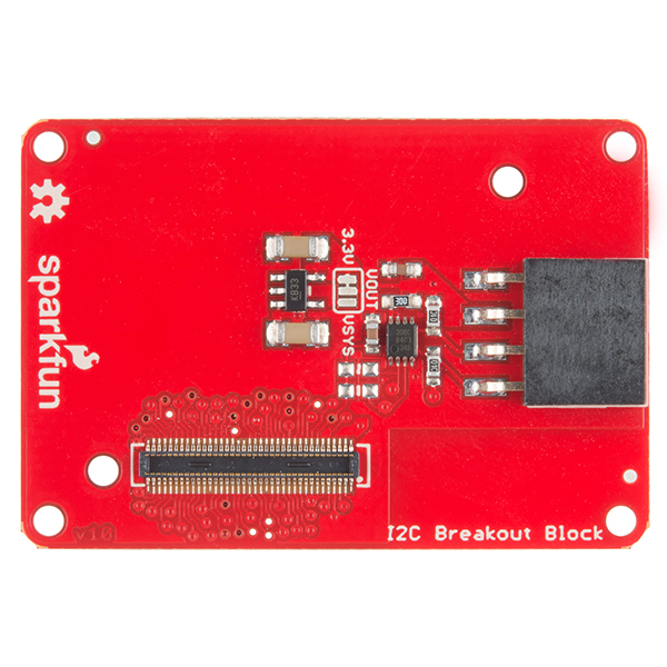
SparkFun Blocks for Intel® Edison - I2C Breakout Block

$
0
0

SparkFun Blocks for Intel® Edison - I2C Breakout Block a learn.sparkfun.com tutorial

Available online at: http://sfe.io/t311

Introduction and Overview

The I2C Breakout Block is a simple way to integrate an I2C device with an Intel Edison stack. The I2C block has the ability to supply 3.3V or VSYS power to external I2C sensors. This opens up the Edison to the great variety of I2C devices we, and others, have to offer.

alt text

I2C Breakout Block

Suggested Reading

If you are unfamiliar with Blocks, take a look at the General Guide to Sparkfun Blocks for Intel Edison.

Other tutorials that may help you on your Edison adventure include:

Board Overview

alt text

I2C Block Functional Diagram TOP

  • I2C Port - Standard I2C port broken out. VOUT provides power based on Level Select position.

  • Level Select - Provides level selection between 3.3V and VSYS levels on VOUT. Default 3.3V

  • Expansion Header - The 70-pin Expansion header breaks out the functionality of the Intel Edison. This header also passes signals and power throughout the stack. These function much like an Arduino Shield.

Using the I2C Breakout Block

To use the I2C Breakout Block, attach an Intel Edison to the back of the board or add it to your current stack. Blocks can be stacked without hardware, but it leaves the expansion connectors unprotected from mechanical stress.

alt text

I2C Block Installed

We have a nice Hardware Pack available that gives enough hardware to secure three blocks and an Edison.

alt text

Intel Edison Hardware Pack

NOTE: The I2C Breakout Block does not have console access or a power supply. It is recommended to use a console communication block in conjunction with this block like ones found in the General Guide to Sparkfun Blocks for Intel Edison.

Example

In our example, we will show how to connect and scan for the SparkFun RGB and Gesture Sensor. Solder a 4-pin section of our Right Angle Break Away Male Headers to the breakout board. Plug the board into the I2C Brekaout Block, and you’re done with the hardware connection.

alt text

SparkFun RGB and Gesture Sensor Installed

To find the I2C device in the console, type the following command. Note the I2C bus we will use is bus 1.

i2cdetect -y -r 1

We see that the device appears on address 0x39 as expected.

     0  1  2  3  4  5  6  7  8  9  a  b  c  d  e  f
00:          -- -- -- -- -- -- -- -- -- -- -- -- --
10: -- -- -- -- -- -- -- -- -- -- -- -- -- -- -- --
20: -- -- -- -- -- -- -- -- -- -- -- -- -- -- -- --
30: -- -- -- -- -- -- -- -- -- 39 -- -- -- -- -- --
40: -- -- -- -- -- -- -- -- -- -- -- -- -- -- -- --
50: -- -- -- -- -- -- -- -- -- -- -- -- -- -- -- --
60: -- -- -- -- -- -- -- -- -- -- -- -- -- -- -- --
70: -- -- -- -- -- -- -- --

To use the SparkFun RGB and Gesture Sensor in your project, you can modify the code from the RGB and Gesture Sensor Hookup Guide to run on your Edison. Using the Arduino IDE for Edison, the demo should work out of the box!

Using 5V Devices

There is a way to modify the I2C block to accept 5V logic. Cut the voltage select jumper, but do not re-connect to either VSYS or 3.3V. You will now need to supply your own 5V voltage (for your sensors) externally. You can solder a 5V supply to the center pad OR use the VOUT pin on the connector. Supplying 5V through the VOUT trace will allow you to plug sensors in without modification.

alt text

Resources and Going Further

Now that you have had a brief overview of the I2C Breakout Block, take a look at some of these other tutorials. These tutorials cover programming, Block stacking, and interfacing with the Intel® Edison ecosystems.

Edison General Topics:

Block Specific Topics:


learn.sparkfun.com |CC BY-SA 3.0 | SparkFun Electronics | Niwot, Colorado
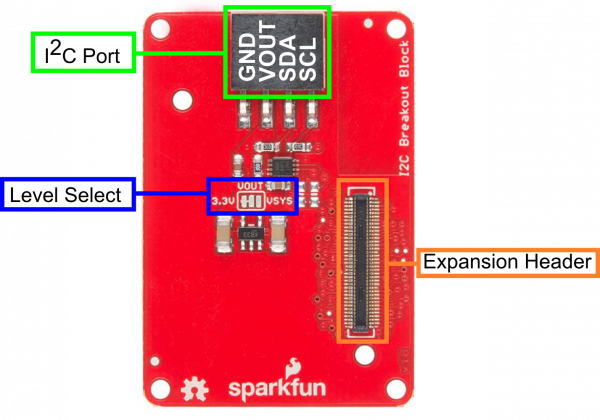
SparkFun Blocks for Intel® Edison - UART Block

$
0
0

SparkFun Blocks for Intel® Edison - UART Block a learn.sparkfun.com tutorial

Available online at: http://sfe.io/t277

Introduction

The UART Block provides a level shifted interface to the console port or second UART port. This is a great solution when USB is not an option. This allows the Edison module to be interfaced with legacy hardware by providing a protected signal interface. Using a RS232 Shifter, it is possible to connect an Edison to RS232 devices commonly found in older automation equipment and instrumentation. The UART Block paired with a 5V Compatible FTDI device, such as our FTDI Basic Breakout, will power an Edison Stack.

alt text

UART Block

Suggested Reading

If you are unfamiliar with Blocks, take a look at the General Guide to Sparkfun Blocks for Intel Edison.

Other tutorials that may help you on your Edison adventure include:

Board Overview

alt text

UART Block Functional Diagram

  • UART Header - Standard FTDI header with RX, TX, VCC, and GND broken out.

  • Select Switch - Select between Console (UART2) and UART1

  • Power Button - The power switch is connected to the “PWRBTN” line on the Edison. This give the user the ability to place an Edison in sleep or power down the module completely. This does not affect power to other Blocks in the stack.

  • Power LED - The power LED illuminates when power is present on VSYS. This can come from the Console Block, or any other powered Block in the stack.

  • LED Jumper - If power consumption is an issue, cut each jumper to disable LED

  • Expansion Header - The 70-pin Expansion header breaks out the functionality of the Intel Edison. This header also passes signals and power throughout the stack. These function much like an Arduino Shield.

Using the UART Block

To use the UART Block, attach an Intel Edison to the back of the board or add it to your current stack. Blocks can be stacked without hardware, but it leaves the expansion connectors unprotected from mechanical stress.

alt text

UART Block Installed

We have a nice Hardware Pack available that gives enough hardware to secure three blocks and an Edison.

alt text

Intel Edison Hardware Pack

Using the Block in the Middle of a Stack

If you need to use the UART block in the middle of a stack, it may be necessary to file or sand the FTDI connector. The connector is slightly larger than the 3mm clearance allowed by the expansion connectors. It is preferred that the user place this Block a the bottom of a stack.

alt text

File or Sand the Connector Here

Using the Block with our FTDI Accessories.

The UART Block can be used with our 5V FTDI Basic.

alt text

FTDI 5V Basic Installed

Connecting to the Console

Once you have connected your hardware to your UART -> Serial device of choice, plug the USB side of the device into the USB port on your computer. If you do not have FTDI drivers currently installed, you’ll need to download and install them before using your Edison. Visit our tutorial for instructions on how to install the drivers. After you have ensured that the drivers are installed and your device is running, open your favorite terminal program and point it to the USB-serial connection. We have another tutorial to explain terminal programs and how to use them.

The standard Baud Rate is 115200bps.

Once a terminal is active you are ready to explore!

alt text

Using the Power Button

The power button on the Edison brings a unique feature commonly not found on single board computers. The power button behaves much like the power buttons on desktop and laptop computers.

  • While powered, Holding the power button for ~10 seconds will power down the Edison.
  • While un-powered, pressing the power button momentarily will reboot the Edison.
  • While powered, pressing the power button momentarily will place the Edison in sleep mode.
  • While in sleep mode, pressing the power button momentarily will wake the Edison.

Resources and Going Further

Now that you have had a brief overview of the UART Block, take a look at some of these other tutorials. These tutorials cover programming, Block stacking, and interfacing with the Intel Edison ecosystems.

Edison General Topics:

Block Specific Topics:


learn.sparkfun.com |CC BY-SA 3.0 | SparkFun Electronics | Niwot, Colorado
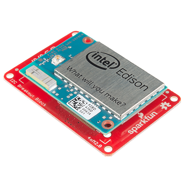
VL6180 Hookup Guide

$
0
0

VL6180 Hookup Guide a learn.sparkfun.com tutorial

Available online at: http://sfe.io/t257

Introduction

alt text

The VL6180 is a Time of Flight (TOF) distance sensor with an I2C (“Wire”) interface. This Hookup Guide will cover two boards. The VL6180 Breakout and the VL6180 Sensor. These boards are very similar in function though the Vl6180 Sensor has additional hardware for level shifting and voltage regulation.

Many distance sensors rely on reflected light intensity or reflected angles to determine range. This sensor uses a precise clock to measure the time it takes light to bounce back from a surface. This is a great benefit over other methods because it can be much more accurate and more immune to noise. This sensor is commonly found in cellphones as the sensor that detects when the caller is holding their phone to their ear.

Covered in this Tutorial

We will show you how to connect this sensor to an Arduino microcontroller and use the included software library to get measurements out of the sensor. (If you’re using a different type of microcomputer these instructions and source code may still help.)

Suggested Reading

This part is easy to use. But before you start, we recommend the following background knowledge:

Board Overview - VL6180 Breakout

alt text

VL6180 Breakout Diagram

The VL6180 Breakout is as simple as it gets. Only the required passives are populated to give users the smallest, most cost effective way to use multiple sensors in a project.

  • Pull-up Enable - Defaulted to enable, two required pull-up resistors are attached to the I2C lines. Remove solder jumper on all but one unit if using multiple sensors on the same bus.
  • VL6180 Sensor - The sensor by itself is very small, only passive components are necessary to complete the circuit.

NOTE: This device only accepts 2.8V input and logic. You must provide a 2.8V voltage source and level shifting to 3.3V and 5V devices.

Board Overview - VL6180 Sensor

alt text

VL6180 Sensor Diagram

The VL6180 Sensor is very similar to the VL6180 Breakout with some noted additions.

  • 2.8V Regulator - Provides the required 2.8V for the sensor
  • I2C level shifter - Provides logic level conversion from 2.8V to VCC (provided by the user)
  • Pull-up Enable - Defaulted to enable, two required pull-up resistors are attached to the I2C lines. Remove solder jumper if using multiple sensors on the same bus.
  • VL6180 Sensor

alt text

VL6180 Sensor and Sharp GP2Y0A41SK0F Comparison

Another thing to note is the form factor of the sensor itself. Many small robotics platforms have integrated hole patterns for the long time favorite Sharp IR sensor line. This allows the VL6180 Sensor to be a near drop-in replacement for most Sharp sensors.

Connecting the Hardware

Using the VL6180 Breakout

To use the VL6180 Breakout, follow the diagram below. One important thing to note is you MUST use a 3.3v Pro-Mini for this to work. We are cheating the 2.8v Level shifting rules in this hookup. Since I2C is an active low signal, we will use the pull-up resistors on the breakout to provide our logic voltage. We have a great I2C tutorial that explains this in more detail. To provide the required 2.8V we are using an LM317 regulator. The output voltage is tuned to 2.8V with the two resistors shown.

alt text

Wiring Diagram for VL6180 Breakout and 3.3v Pro-Mini

NOTE: To use this diagram make sure the two pull-up resistors on the Pro-Mini are NOT poulated.

alt text

Unpopulated Pro-Mini Pull-ups

Using the VL6180 Sensor

To use the Sensor version of the VL6180, things are much simpler. The board carries its own level shifting and regulation. The VL6180 Sensor can work with 3.3-5V Logic and power.

alt text

Library Install and Sample Sketch

To use either the VL6180 Sensor or Breakout, you will need some supporting software. If you are using an Arduino, then you are in luck! We created an Arduino library that makes the VL6180 easy to use. Click the button below to download the latest version of the VL6180 Library.

Download the Arduino Library!

Unzip the downloaded file and navigate to <your download directory>\SparkFun_VL6180_Time_of_Flight_Library-master.zip\SparkFun_VL6180_Time_of_Flight_Library-master\Libraries.

alt text

Follow this guide on installing Arduino libraries to install the files within the SFE_VL6180x directory as an Arduino library.

There is a sample sketch associated with the Library. VL6180X_demo reads the distance and light outputs and reports them to the screen.

alt text

Demo Program Found in Examples

alt text

Demo Program Output

Resources and Going Further

Now that we have covered some of the basic features of the Vl6180 Sensor and Breakout, check out some of these other tutorials and helpful links.


learn.sparkfun.com |CC BY-SA 3.0 | SparkFun Electronics | Niwot, Colorado
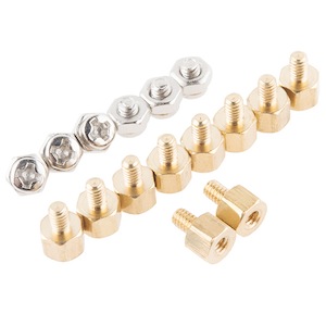
LilyPad Simple Power Hookup Guide

$
0
0

LilyPad Simple Power Hookup Guide a learn.sparkfun.com tutorial

Available online at: http://sfe.io/t242

Overview

The LilyPad Simple Power is a basic power board that enables you to power your wearable circuit with a lipo battery. It also allows battery charging in the circuit via microUSB cable, and it provides a nice on/off switch for your project.

LilyPad Simple Power

The LilyPad Simple Power. Small and simple!

Being part of the LilyPad line of boards, you can wash this PCB even after it’s been sewn to a garment. Just remember to remove the battery first before doing any washing!

With this quick tutorial, you’ll learn how to get started with the Simple Power.

Suggested Reading

Please check out the following tutorials, if you aren’t familiar with any of the topics.

Hardware Overview

True to its name, the LilyPad Simple power is really simple! There’s only a few features you need to be aware of.

alt text

Battery JST Connector

The Simple Power is designed to work with 3.7V lipo batteries. In order to connect the battery to the board, there should be a female JST connector on the battery you would like to use. Check out a list of compatible batteries here.

microUSB Connector

This allows you to charge your battery via a computer USB port, using a microB USB cable.

Positive/Negative Terminals

These sew taps are the connection points from where the power to your circuit will flow. The positive terminal outputs 3.7V, and the negative terminal is the ground (GND) connection.

On/Off Switch

This switch enables and disables power to flow out of the LilyPad Simple board. When it is in the ‘on’ position, you can measure the battery voltage across the positive (+) and negative (-) terminals. When it is in the ‘off’ position, there is no measurable voltage output from the board.

Mounting Holes

These four holes spaced across the board are designed as additional anchoring sew taps. They are not conductive, and have no electrical functionality.

Hardware Hookup

In our example, we are going to assume you are powering a basic LilyPad LED. However, you can use the Simple Power to power a LilyPad Main board, or various other products.

One thing to note about the Simple Power- it is designed for e-textile applications, but you can solder to the board. Just keep in mind it’s going to take more solder and more heat to attach wires to the sew taps.

Basic Simple Power Circuit

Our example circuit using the Simple Power and a LilyPad LED.

Find the ‘+’ terminal on the Simple Power and run a stitch/wire to the ‘+’ sew tap on the LED (or whatever board you are powering). Then run a wire or stitch from the ‘-’ terminal on the Simple Power to the ‘-’ sew tap on the LED. If you are using conductive thread, make sure you don’t let the two lines touch! This will short out your battery, possibly short out your Simple Power, and you’ll have a bad time.

Once your boards are connected, plug in your battery, and flip the Simple Power switch to the ‘on’ position. Bask in that happy LED glow!

Charging the Battery

If your battery runs down, have no fear! Simply plug in a microUSB cable into your computer and also into the LilyPad Simple board, and have some patience. There’s a yellow LED that indicates when the board is charging the battery. The board may also get warm while charging, but this is totally normal. Charging times will vary depending on the capacity of the battery connected to the Simple Power.

Resources and Going Further

Going Further

Now that you know how to use the LilyPad Simple Power, you can start integrating it into your own projects. If you need to check out the design files for the board, you can find them in the GitHub repo. You can also dig into the datasheet for the MCP7383 charger IC here.

Additional Resources

If you have any feedback, please visit the comments or contact our technical support team at TechSupport@sparkfun.com.

Check out these additional resources for more information and other project ideas.


learn.sparkfun.com |CC BY-SA 3.0 | SparkFun Electronics | Niwot, Colorado
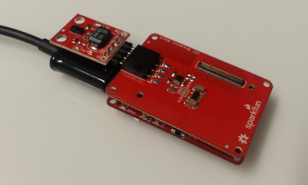
SparkFun Blocks for Intel® Edison - OLED Block

$
0
0

SparkFun Blocks for Intel® Edison - OLED Block a learn.sparkfun.com tutorial

Available online at: http://sfe.io/t278

Introduction

The Intel® Edison is a powerful single-board computer, but it lacks any form of display output. The OLED Block serves to provide at least some form of output capabilities to the powerful Edison module. The crisp blue-on-black OLED display is 64x48 pixels – about 1.6 inches across the diagonal. It’s small, but that allows it to maintain the Edison’s tiny form factor. And, it still leaves room for text or games.

OLED Block in Action

Speaking of games, the board also includes a 4-way joystick (with a select switch) and two momentary push buttons. Someone start working on porting an NES emulator to the Edison!

Suggested Reading

If you are unfamiliar with Blocks, take a look at the General Guide to Sparkfun Blocks for Intel Edison.

Other tutorials that may help you on your Edison adventure include:

Board Overview

Before we jump into using the OLED Block, here’s a quick overview of what features and components the board includes:

Annotated OLED Block

Button Pin Mapping

In total, the OLED block has seven button/joystick inputs, here’s how they’re mapped to the Edison’s GPIO pins:

ButtonEdison GPIO Pin
Up47
Down44
Left165
Right45
Select48
A49
B46

Note 1: “Up” is towards the top of the screen (the side without the black ribbon connector).
Note 2: The “Select” button refers to a downward press on the joystick.

Battery Supply Input

A pair of through-holes below the bottom of the screen, labeled “+” and “-”, can be used to supply a battery input to the Edison.

OLED battery supply input

This voltage is supplied directly to the Edison’s VSYS pin, and should be between 3.3 to 4.5V. That voltage is not regulated, so be very careful applying voltage to this input. A single-cell Lithium Polymer battery is a perfect, mobile choice for this power supply.

Jumpers

The bottom of the OLED block is filled with jumpers, which allow you to tailor the block to fit your project.

OLED Board Jumpers

Seven of the eight jumpers allow you to disconnect any of the joystick or button inputs from the Edison, in case you need those GPIO for another purpose. Keep in mind, if you cut any of the jumpers, that button will serve no purpose unless you wire it to another pin or re-solder the jumper.

The “CS” jumper allows you to flip the OLED’s chip-select pin from “FS0” (default) to “FS1”. If you switch this pin, you’ll need to modify the code accordingly.

Using the OLED Block

To use the OLED Block, attach it to either an Edison or another SparkFun Block. This board, unlike most Edison blocks is only single-sided, so it must be at the top of your stack (you don’t want to cover that beautiful display!).

The OLED block can supply power to the Edison, using the battery supply input, but we recommend using it in conjunction with a development block like the Console Block or Base Block.

OLED Block stacked

OLED Block in a stack with the Edison and a Console Block.

Blocks can be stacked without hardware, but it leaves the expansion connectors unprotected from mechanical stress. We recommend adding a few screws from our Hardware Pack between the OLED and the next block.

Edison Block Hardware Pack

Intel Edison Hardware Pack

Programming for the OLED Block

It’ll take a bit of coding to get your display up-and-running. The Edison has all sorts of programming-language support, but we’ve decided to stick with C++ to control the display.

We’ve written a simple library to help get you started. You can download the latest version from our GitHub repository, or click the button below to get it in a zip folder.

Download the C++ Library and Example

The example code includes a simple makefile that should compile directly on the Edison. But first, you need to get these files onto the Edison. There are a few ways to do that. For example, you could get the Edison connected to a WiFi network and SSH it over – check out the SSH how-to section of our Getting Started with Edison tutorial for help with that. Even better than that, you could follow along with our Programming the Intel® Edison: Beyond the Arduino IDE and set up Eclipse to remotely upload the code – even remotely compile it on your development computer.

Once you’ve loaded the code, navigate to the “pong” folder and type make. The dependencies (spi, gpio, and oled libraries) will build, then the main example code (“oled_pong.cpp”) will build to create an “oled_pong” executable.

Compilation example

After the code has successfully been built, type ./oled_pong to play. This should trigger the OLED to light up and start a game of pong. Have fun!

Pong in action

Edison Pong in action!

Using the OLED Library

The OLED library, included in the download above, allows you to draw anything from pixels and lines to shapes and text on the little display.

The “pong” example code should serve as an excellent teaching tool. To begin, create an instance of the edOLED class, then initialize the display like this:

language:c
edOLED oled;
...
oled.begin()
oled.clear(ALL);
oled.display();

Then, continue to use the oled object to draw pixels, lines, and other shapes like this:

language:c
oled.pixel(x, y);   // Draw a pixel at x,y
oled.line(x0, y0, x1, y1);  // Draw a line from x0,y0 to x1,y1
oled.rect(x, y, width, height); // Draw a rectangle, begnning at x,y with a set width and height
oled.circle(x, y, radius);  // Draw a circle, centered at x,y with a set radius

Or you can draw text on the screen with function calls like:

language:c
oled.setCursor(x, y);   // Set the text cursor to x,y
oled.setFontType([0:3]);    // Set the font to one of four types.
oled.print(char);       // Draw a character
oled.write(char *);     // Draw an array of characters (string)
oled.write(int);        // Draw an integer value

Don’t forget: the OLED’s display will not update until you call oled.display().

Using the GPIO Library

The “gpio” library, also included with the example code, can be used to listen for button presses. Again, the pong example should serve as a good place to start learning how to use the library.

First, you’ll need to initialize the pins:

language:c
gpio BUTTON_UP(47, INPUT);  // UP button is tied to GPIO 47
gpio BUTTON_DOWN(44, INPUT); // Down is tied to GPIO 44
gpio BUTTON_LEFT(165, INPUT); // Left is tied to GPIO 165
gpio BUTTON_RIGHT(45, INPUT); // Right is tied to GPIO 45
gpio BUTTON_SELECT(48, INPUT); // Select (pushing the joystick down) is GPIO 48
gpio BUTTON_A(49, INPUT); // Button A is GPIO 49
gpio BUTTON_B(46, INPUT); // Button B is GPiO 46

Then you can use the readPin() function of the gpio class to see if they’re HIGH or LOW. The buttons are all pulled high, so they’ll read as LOW if they’re pressed down.

language:c
if (BUTTON_UP.pinRead() == LOW)
{
    printf("You're pressing down");
}
if (BUTTON_A.pinRead() == LOW)
{
    printf("You're pressing the A button");
}

Hopefully that brief primer will get you ready to begin developing for the Edison OLED Block. If you haven’t already, we really recommend following our Programming the Intel® Edison tutorial for help setting up your programming toolchain.

Resources and Going Further

Now that you have had a brief overview of the OLED Block, take a look at some of these other tutorials. These tutorials cover programming, Block stacking, and interfacing with the Intel Edison ecosystems.


learn.sparkfun.com |CC BY-SA 3.0 | SparkFun Electronics | Niwot, Colorado
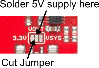

Big Easy Driver Hookup Guide

$
0
0

Big Easy Driver Hookup Guide a learn.sparkfun.com tutorial

Available online at: http://sfe.io/t239

Introduction

The Big Easy Driver gives you the capability to drive stepper motors that pull up to 2A/phase. This driver defaults to 16 step microstepping mode, and gives you control of motor speed and location.

SparkFun Big Easy Driver

Materials Required

To follow along with this tutorial, we recommend you have access to the following materials.

You can either solder screw terminals or standard headers for attaching things to the Big Easy Driver. The best option for you will depend on your application.

Suggested Reading

If you aren’t familiar with the following concepts, we recommend reviewing them before beginning to work with the Big Easy Driver.

Hardware Overview

The Big Easy Driver is designed around the Allegro A4988 motor driver. Each pin present on the board has two connection points. The first, which are the pins closest to the center of the board, are spaced out to fit standard 0.1" headers. The secondary connection points are closest to the edge of the board, and are spaced to fit 2-pin screw terminals. You can use whichever pin connections work best for your project. Functionality between the two sets does not change.

Pin Descriptions

Several pins of the A4988 IC are broken out on the Big Easy Driver, allowing direct connection to a bi-polar stepper motor, as well as a microcontroller.

Board Top Pins

  • Coil A+: DMOS Full Bridge 1 Output B. Half of connection point for bi-polar stepper motor coil A.

  • Coil A-: DMOS Full Bridge 1 Output A. Other half of connection point for bi-polar stepper motor coil A.

  • Coil B+: DMOS Full Bridge 2 Output B. Half of connection point for bi-polar stepper motor coil B.

  • Coil B-: DMOS Full Bridge 2 Output A. Other half of connection point for bi-polar stepper motor coil B.

  • GND: Ground.

  • M+: Power supply. 8V - 35V.

Top Pins

Bottom Pins

  • ENABLE: Logic Input. Enables the FET functionality within the motor driver. If set to HIGH, the FETs will be disabled, and the IC will not drive the motor. If set to LOW, all FETs will be enabled, allowing motor control.

  • MS1: Logic Input. Microstep Select 1 has a pull-down resistance of 100 kOhms. See truth table below for HIGH/LOW functionality.

  • MS2: Logic Input. Microstep Select 2 has a pull-down resistance of 50 kOhms. See truth table below for HIGH/LOW functionality.

  • MS3: Logic Input. Microstep Select 3 has a pull-down resistance of 100 kOhms. See truth table below for HIGH/LOW functionality.

Microstep Select Resolution Truth Table
MS1 MS2 MS3 Microstep Resolution Excitation Mode
LLLFull Step2 Phase
HLLHalf Step1-2 Phase
LHLQuarter StepW1-2 Phase
HHLEigth Step2W1-2 Phase
HHHSixteenth Step4W1-2 Phase

  • RST: Logic Input. When set LOW, all STEP commands are ignored and all FET functionality is turned off. The translator is set to the Home state as well. This must be set HIGH to enable functionality of the motor driver.

  • SLEEP: Logic Input. When set to LOW, the A4988 enters sleep mode, and disables functionality of the FETs, internal current regulator and charge pump. When switching this pin to HIGH to wake up the IC, allow 1 ms of delay before sending a STEP signal. The IC will return the motor to the starting position upon receiving a HIGH signal on this pin.

  • VCC: Logic Supply.

  • GND: Ground.

  • STEP: Logic Input. Any transition on this pin from LOW to HIGH will trigger the motor to step forward one step. Direction and size of step is controlled by DIR and MSx pin settings.

  • DIR: Logic Input. This pin determines the direction of motor rotation. Changes in state from HIGH to LOW or LOW to HIGH only take effect on the next rising edge of the STEP command.

Bottom Pins

Solder Jumpers

There are two solder jumpers present on the board.

  • APWR - This solder jumper allows the user to use VCC as a power supply for external devices. The Big Easy Driver requires 15mA to operate, and the voltage regulator that outputs VCC can only supply 100mA. Keep this in mind when planning to power any additional devices off of VCC.

  • 5V/3.3V - This jumper allows the user to set the configuration of VCC between 3.3V or 5V. With the jumper open, VCC will be 5V. If the jumper is closed, VCC is 3.3V.

Solder Jumpers

Potentiometer

The potentiometer on board is included to allow users the ability to select the current provided to the motor. It ranges from 0mA to 2000mA (2A). This will require you to be aware what current range your motor can handle - check the motor’s data sheet for the current settings.

Potentiometer

If you can’t find this information, have no fear – you can still find the proper setting for the potentiometer. First, set it to the lowest setting of the potentiometer. Keep in mind that the potentiometer is delicate, so be careful to not force the potentiometer past the mechanical stops when turning it. Once you have the motor being driven at a slow, yet steady speed, slowly turn the potentiometer and pay attention to the motor’s behavior. You should find a sweet spot where the motor doesn’t skip or jerk between steps.

Hardware Hookup

Connect Motor Coil Wires

You will need to determine the wire pairs for each coil on the motor you plan to use. The most reliable method to do this is to check the datasheet for the motor.

alt text

Coil wire diagram from the datasheet for our 68 oz.in, NEMA -17 Stepper Motor.

However, if you are using a 4-wire or 6-wire stepper motor, it is still possible to determine the coil wire pairs without the datasheet.

For a 4-wire motor, take one wire and check its resistance against each of the three remaining wires. Whichever wire shows the lowest resistance against the first wire is the pair mate. The remaining two wires should show similar resistance between the two of them.

For a 6-wire motor, you will need to determine which of three the wires go together for one coil. Pick one wire, and test this against all other wires. Two wires should show some resistance between them and the first wire picked, while the other three will show no connection at all. Once the three wires for one coil have been determined, find two of the three that show the highest resistance between them. These will be your two coil wires. Repeat for the second group of three wires.

Once you have determined the coil wire pairs, you will need to attach them to the Big Easy Driver. The first coil pair should be plugged into Coil A+ and Coil A-, while the second coil pair plugs into Coil B+ and Coil B-. There is no polarity on the coils, so you don’t need to worry about plugging in a coil backwards on the board. In our example, we are using a 4-coil motor. The connections between the Big Easy Driver and motor are as follows.

Big Easy Driver → Motor

  • A+ → Red Wire
  • A- → Green Wire
  • B+ → Blue Wire
  • B- → Yellow Wire
Note: Do not connect or disconnect the motor while the Big Easy Driver is powered.

Connect a Power Supply

Once your motor is connected, you can then connect a power supply to the Big Easy Driver. You can use any kind of power supply (desktop, wall adapter, battery power, etc.), but verify that whatever choice you go with is capable of providing up to 2A and falls in the range of 8V to 35V.

Connect the power supply to M+ and GND. REMEMBER to disconnect the power before connecting/disconnecting your motor.

Connect a Microcontroller

For this example, we will be using an Arduino Uno R3. However, any microcontroller that works at 3.3V or 5V logic and has digital I/O with PWM capability will work for this example.

Here are the following pin connections for our example.

Uno → Big Easy Driver

  • D2 → DIR
  • D3 → STEP
  • D4 → MS1
  • D5 → MS2
  • D6 → MS3
  • D7 → ENABLE
  • GND → GND

Final Circuit

Once everything is connected, your setup should look like this:

Big Easy Driver Hookup Image

Arduino Code

Basic Arduino Example

Now that you have the hardware hooked up and ready to go, it’s time to get the code uploaded. Download the Arduino code here, or for the most up-to-date code available, please check the GitHub repository. If you need a reminder as to how to install an Arduino library, please check out our tutorial here.

The first section of the sketch defines all of the pin connections between the Arduino and the Big Easy Driver. It also sets these pins as outputs, and puts them to the proper logic levels to begin driving the motor.

language:c
//Declare pin functions on Arduino
#define stp 2
#define dir 3
#define MS1 4
#define MS2 5
#define MS3 6
#define EN  7

//Declare variables for functions
char user_input;
int x;
int y;
int state;

void setup() {
  pinMode(stp, OUTPUT);
  pinMode(dir, OUTPUT);
  pinMode(MS1, OUTPUT);
  pinMode(MS2, OUTPUT);
  pinMode(MS3, OUTPUT);
  pinMode(EN, OUTPUT);
  resetBEDPins(); //Set step, direction, microstep and enable pins to default states
  Serial.begin(9600); //Open Serial connection for debugging
  Serial.println("Begin motor control");
  Serial.println();
  //Print function list for user selection
  Serial.println("Enter number for control option:");
  Serial.println("1. Turn at default microstep mode.");
  Serial.println("2. Reverse direction at default microstep mode.");
  Serial.println("3. Turn at 1/16th microstep mode.");
  Serial.println("4. Step forward and reverse directions.");
  Serial.println();
}

One thing worth noting is that the code also initializes the serial connection at 9600bps. This enables the user (you!) to control the motor’s functionality and debug your circuit if needed.

The main loop of the code is pretty simple. The Arduino scans the serial port for input from the user. When it is received, it’s compared to the four possible functions for the motor, which are triggered from user input. If no valid input is received, the Arduino prints an error over the serial port. After the requested function is completed, the pins on the Big Easy Driver are reset to the defaults.

language:c
//Main loop
void loop() {
  while(Serial.available()){
      user_input = Serial.read(); //Read user input and trigger appropriate function
      digitalWrite(EN, LOW); //Pull enable pin low to set FETs active and allow motor control
      if (user_input =='1')
      {
         StepForwardDefault();
      }
      else if(user_input =='2')
      {
        ReverseStepDefault();
      }
      else if(user_input =='3')
      {
        SmallStepMode();
      }
      else if(user_input =='4')
      {
        ForwardBackwardStep();
      }
      else
      {
        Serial.println("Invalid option entered.");
      }
      resetBEDPins();
  }
}

The first of the four functions this demo sketch enables is a basic example to show the motor spinning in one direction. The direction pin is held LOW, which for our sketch, we define as the ‘foreword’ direction. The sketch then transitions the step pin HIGH, pauses, and then pulls it LOW. Remember, the motor only steps when the step pin transitions from LOW to HIGH, thus we have to switch the state of the pin back and forth. This is repeated 1000 times, and then the Arduino requests more user input to determine the next motor activity.

language:c
//Default microstep mode function
void StepForwardDefault()
{
  Serial.println("Moving forward at default step mode.");
  digitalWrite(dir, LOW); //Pull direction pin low to move "forward"
  for(x= 1; x<1000; x++)  //Loop the forward stepping enough times for motion to be visible
  {
    digitalWrite(stp,HIGH); //Trigger one step forward
    delay(1);
    digitalWrite(stp,LOW); //Pull step pin low so it can be triggered again
    delay(1);
  }
  Serial.println("Enter new option");
  Serial.println();
}

The reverse function works exactly the same as the forward function. The only difference is that instead of pulling the direction pin LOW, we set it HIGH, thus switching the direction of the motor spin. One thing you can try on either of these first two functions is modifying the motor speed by changing the value in delay(). It is currently set to 1 microsecond, making each step pulse take 2 microseconds. Increasing the delay will slow down the motor, while decreasing the delay will speed up the motor.

language:c
//Reverse default microstep mode function
void ReverseStepDefault()
{
  Serial.println("Moving in reverse at default step mode.");
  digitalWrite(dir, HIGH); //Pull direction pin high to move in "reverse"
  for(x= 1; x<1000; x++)  //Loop the stepping enough times for motion to be visible
  {
    digitalWrite(stp,HIGH); //Trigger one step
    delay(1);
    digitalWrite(stp,LOW); //Pull step pin low so it can be triggered again
    delay(1);
  }
  Serial.println("Enter new option");
  Serial.println();
}

The third function shows off the different microstepping functionality that the Big Easy Driver provides. To enable the motor to step in 1/16th microsteps, we must set MS1, MS2, and MS3 HIGH. This sets the logic of the board to 1/16th microstep mode. If you want to have the motor step at a different microstep mode, change the settings for one of the MS# pins. Check the truth table in the Hardware Overview section, if you need a reminder of what settings are enabled by the various pin states.

language:c
// 1/16th microstep foward mode function
void SmallStepMode()
{
  Serial.println("Stepping at 1/16th microstep mode.");
  digitalWrite(dir, LOW); //Pull direction pin low to move "forward"
  digitalWrite(MS1, HIGH); //Pull MS1,MS2, and MS3 high to set logic to 1/16th microstep resolution
  digitalWrite(MS2, HIGH);
  digitalWrite(MS3, HIGH);
  for(x= 1; x<1000; x++)  //Loop the forward stepping enough times for motion to be visible
  {
    digitalWrite(stp,HIGH); //Trigger one step forward
    delay(1);
    digitalWrite(stp,LOW); //Pull step pin low so it can be triggered again
    delay(1);
  }
  Serial.println("Enter new option");
  Serial.println();
}

The final motor function available shows how the motor can change direction on the fly. The function works just as the forward and reverse functions above, but switches between states quickly. This example will step the motor 1000 steps forward and then reverse 1000 steps. This allows you to precisely move something with the motor in one direction, and return to the starting position exactly. Precise position control is a great benefit of stepper motors!

language:c
//Forward/reverse stepping function
void ForwardBackwardStep()
{
  Serial.println("Alternate between stepping forward and reverse.");
  for(x= 1; x<5; x++)  //Loop the forward stepping enough times for motion to be visible
  {
    //Read direction pin state and change it
    state=digitalRead(dir);
    if(state == HIGH)
    {
      digitalWrite(dir, LOW);
    }
    else if(state ==LOW)
    {
      digitalWrite(dir,HIGH);
    }

    for(y=1; y<1000; y++)
    {
      digitalWrite(stp,HIGH); //Trigger one step
      delay(1);
      digitalWrite(stp,LOW); //Pull step pin low so it can be triggered again
      delay(1);
    }
  }
  Serial.println("Enter new option");
  Serial.println();
}

Additional Examples

In addition to the example here, you can also install the AccelStepper Library. There are some additional examples with this library that may be beneficial to you for use with your Big Easy Driver. Download this and install the library in your Arduino libraries directory.

Resources and Going Further

Going Further

Now that you’ve successfully got your Big Easy Driver up and running, it’s time to incorporate it into your own project!

If you have any feedback, please visit the comments or contact our technical support team at TechSupport@sparkfun.com.

Additional Resources

Check out these additional resources for more information and other project ideas.


learn.sparkfun.com |CC BY-SA 3.0 | SparkFun Electronics | Niwot, Colorado
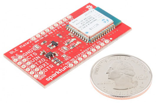
SparkFun Inventor's Kit for MicroView

$
0
0

SparkFun Inventor's Kit for MicroView a learn.sparkfun.com tutorial

Available online at: http://sfe.io/t328

Introduction

Welcome to the SparkFun Inventor’s Kit for MicroView Experiment Guide, or the SIK for MicroView for short. This tutorial will guide you through eleven experiments to help you better understand your MicroView, and, once finished, you should have the knowledge necessary to make your MicroView project dreams a reality.

SparkFun MicroView Learning Kit

Included Materials

Before you do anything, you should make sure that you have all the necessary parts included with the SIK for MicroView. It’s a good idea to familiarize yourself with the parts now, so you know what to look for when it comes time to build the circuits.

Suggested Reading

To make your MicroView experience as enjoyable as possible, we recommend you be familiar with the following concepts before beginning.

MicroView Overview

Before we dive into the experiments, let’s fist familiarize ourselves with the MicroView and its pins.

The MicroView is the first chip-sized Arduino compatible module that lets you see what your Arduino is thinking by using a built-in OLED display. In the heart of MicroView, there is an ATMEL ATmega328P, 5V & 3.3V LDOs and a 64x48 pixel OLED display, together with other passive components that allow the MicroView to operate without any external components other than a power supply.

alt text

Hardware Specifications

  • Display : 64x48 OLED Display
  • Microcontroller : ATmega328P
  • Operating Voltage : 5V
  • Input Voltage : 3.3VDC - 16VDC
  • Digital I/O Pins : 12 (of which 3 provide PWM output)
  • Analog Input Pins : 6
  • Flash Memory : 32 KB
  • SRAM : 2 KB
  • EEPROM : 1 Kilobyte
  • Clock Speed : 16 Mhz
  • No other components required

Pin Configuration

The MicroView has 16 “physical pins” that map to corresponding “Arduino pins” that can be referenced from within your Arduino sketch. For example, Physical Pin2 maps to the Arduino’s pin A5 (analog pin 5).

pinout

Pinout of MicroView on it’s side. The top of the MicroView is on the right. (Click for larger image)

The pin numbering for the MicroView increments as you move anti-clockwise.

The MicroView’s physical Pin1 is denoted by a dot on the underside of the MicroView.

alt text

For more details on pins of MicroView, please refer to the ATmega328P Datasheet.

Programming the MicroView

In order to get your MicroView up and running, there a few easy steps you will need to follow:

  1. Download the FTDI Drivers
  2. Install Arduino software and MicroView Library
  3. Select the right board
  4. Run your first sketch

Step 1 - Download and Install FTDI Drivers

To use the MicroView with the Arduino IDE, you will first need to install the drivers for the FTDI chip on the USB Programmer. Visit our comprehensive tutorial on how to install FDTI drivers, then come on back to continue your MicroView Adventure.

Once you have finished the FTDI driver installation, you will need to prepare your MicroView to be inserted into the computer’s USB port.

If you’re using the USB Programmer, insert the MicroView into the USB Programmer now, if you have not done so already. Please take note that at the back of MicroView, there is a round dot marking showing the Pin 1 of the MicroView where you need to match the Pin 1 of the USB Programmer. Once you have inserted the MicroView into the USB Programmer, you can now insert the USB Programmer into the USB port of the computer as pictured below. If your computer does not have a right-sided USB port, please use a USB Cable Extension to extend the USB port to the front so that you can easily work with the MicroView.

alt text

As an alternative to the USB Programmer, you can use a 5V FTDI Basic Breakout or 5V FTDI Cable instead. Connect the FTDI Basic Breakout board as below, and you are ready to go.

alt text

Step 2 - Install the Arduino Software (IDE)

We will be using the Arduino IDE to program the MicroView. If you have already installed it, skip to installing the library.

Install Arduino IDE and the MicroView Library

If you have not installed the Arduino IDE already, now is the time to do so. Visit our Installing the Arduino IDE tutorial for detailed instructions.

Install MicroView Library

Download MicroView’s library from the MicroView Github repo, or click the link below to download the zip file directly.

MicroView Library GitHub Repo

Save the ZIP file to your download folder, and then unzip the .ZIP file. Find the Library folder under MicroView-master -> Libraries -> SparkFun_Microview.

Open the Arduino IDE, click Sketch, Import Library, and then Add Library.

alt text

Browse to the MicroView folder that was renamed, and select that folder. The MicroView library will be automatically installed.

Click File, Example, and find MicroView Example to confirm the installation.

alt text

If you wish to compile and upload the MicroViewDemo from our example, there is a 3rd party Time library that is required to be installed. Download the Time library and use the same library installation method discussed above to install it into the Arduino IDE.

Step 3 - Select the Right Board

In the Arduino IDE, click Tools, board and select Arduino Uno. Due to the nature of Arduino IDE being not able to detect a board, the COM port (Serial Port) of the MicroView USB Programmer needs to be manually selected by clicking Tools, Serial Port and select the right port that was created in the previous driver installation. Click Upload to upload your first sketch to MicroView.

MicroView is using the same bootloader as Uno. It behaves like an Uno when uploading sketches.

For advance user that like to see MicroView as a board by itself in the IDE, add the following board definition to the boards.txt file. Depending on your setup, the boards.txt file usually located at arduino-version\hardware\arduino folder. Replace arduino-version with the right folder name for your Arduino version installed in your computer.

uview.upload.tool=avrdude
uview.bootloader.tool=avrdude
uview.name=MicroView
uview.upload.protocol=arduino
uview.upload.maximum_size=32256
uview.upload.speed=115200
uview.bootloader.low_fuses=0xff
uview.bootloader.high_fuses=0xde
uview.bootloader.extended_fuses=0x05
uview.bootloader.path=optiboot
uview.bootloader.file=optiboot_atmega328.hex
uview.bootloader.unlock_bits=0x3F
uview.bootloader.lock_bits=0x0F
uview.build.mcu=atmega328p
uview.build.f_cpu=16000000L
uview.build.core=arduino
uview.build.variant=standard

Step 4 - Run Your First Sketch

Select the correct COM port, and you’re ready to upload. Simply cut and paste the sketch below into the Arduino IDE, and click upload.

language:c
#include <MicroView.h>

void setup() {
    uView.begin();              // start MicroView
    uView.clear(PAGE);          // clear page
    uView.print("HelloWorld");  // display HelloWorld
    uView.display();
}

void loop () {}

Once you have uploaded your first sketch, it’s time to get started with the experiments.

Experiment 0: Quick Start

The MicroView comes with a nice quick start experiment preinstalled to get you learning right out of the box without having to upload any code. Using just a few components, you can learn the ins and outs of the MicroView in this first step of the SIK for MicroView.

Unboxing and Setting Up Your MicroView

Remove all parts from the SparkFun Inventor’s Kit for MicroView.

Identify PIN 1 of MicroView based on the following diagram, or refer back to the MicroView Overview section.

alt text

In this guide, when there is a reference for PIN x of MicroView, it is referring to the above diagram’s PIN number. For example, connect PIN 5 and PIN 8 of the MicroView.

MicroView with Factory USB Programmer

The quickest way to get started is to use the USB programmer included in the SIK for MicroView. You will also need

Insert the MicroView to the factory USB Programmer then connect the female end of the USB extension cable to the factory USB Programmer based on the following diagram:

alt text

Connect the male end of the USB extension cable to the computer, and the MicroView demo will start.

MicroView without Factory USB Programmer

If you would like to use the MicroView without the USB Programmer, you will need the following (please note that the 9V battery and snap connector are not included in the SIK for MicroView and will need to be purchased separately):

Connect the required parts based on the diagram below, leave the battery snap connector to the last step:

alt text

As soon as the battery snap connector is snapped to the 9V battery, the MicroView demo will start.

Learn How to Use MicroView

The MicroView is factory pre-programmed with a few simple built-in tutorials to help you get use to inserting jumper wires, resistors and LED. Skip these tutorials if you are already familiar with them. The simple tutorials will start after the demo.

Note: The simple tutorials' diagrams are based on MicroView without the USB Programmer, if you have the USB Programmer, please ignore the battery, red jumper and black jumper. MicroView with USB Programmer gets its power supply from the USB Programmer via the USB cable connected to the computer.

Simple Tutorial 1

Follow the instruction displayed on the MicroView, connect PIN 5 and PIN 8 of the MicroView with a jumper using the following diagram as reference:

alt text

Once you have successfully connected PIN 5 and PIN 8 of the MicroView, a “Well done!” message will be displayed. To proceed to the next simple tutorial, remove the jumper.

Simple Tutorial 2

Follow the instruction displayed on the MicroView, connect PIN 3 and PIN 8 of the MicroView with a jumper using the following diagram as reference:

alt text

Once you have successfully connected PIN 3 and PIN 8 of the MicroView, a “Well done!” message will be displayed. To proceed to the next simple tutorial, remove the jumper.

Simple Tutorial 3

Follow the instruction displayed on the MicroView, connect PIN 2 and PIN 8 of the MicroView with a jumper using the following diagram as reference:

alt text

Once you have successfully connected PIN 2 and PIN 8 of the MicroView, a “Well done!” message will be displayed. To proceed to the next simple tutorial, remove the jumper.

Simple Tutorial 4

Follow the instruction displayed on the MicroView, connect PIN 4 and PIN 8 of the MicroView with a 330 ohm resistor using the following diagram as reference:

alt text

Once you have successfully connected PIN 4 and PIN 8 of the MicroView with the resistor, a “Well done!” message will be displayed. To proceed to the next simple tutorial, remove the resistor.

Simple Tutorial 5

Follow the instruction displayed on the MicroView, connect PIN 4 and PIN 8 of the MicroView with a 10K ohm resistor using the following diagram as reference:

alt text

Once you have successfully connected PIN 4 and PIN 8 of the MicroView with the resistor, a “Well done!” message will be displayed. To proceed to the next simple tutorial, remove the resistor.

Simple Tutorial 6

Follow the instruction displayed on the MicroView, connect PIN 5 and PIN 8 of the MicroView with a 330 ohm resistor using the following diagram as reference:

alt text

With the resistor still at the same place, insert a LED with both of the pins at PIN 4 and PIN 5 of MicroView respectively using the following diagram as reference.

alt text

The MicroView is able to detect if the LED is inserted with the correct polarity, if the LED does not blink, remove the LED and turn the pins the other way round and connect them to PIN 4 and PIN 5 of the MicroView.

With that, you are now ready to upload code and begin building the experiments in this guide.

Experiment 1: Blinking an LED

LEDs (light-emitting diodes) are small, powerful lights that are used in many different applications. To start off the MicroView course, we will work on blinking an LED. That’s right – it’s as simple as turning a light on and off. It might not seem like much, but establishing this important baseline will give you a solid foundation as we work toward more complex experiments. Blink is the “Hello World” of hardware.

Parts Needed

You will need the following parts:

  • 1x LED
  • 1x 330Ω Resistor (Orange, Orange, Brown, Gold)

Breadboard Setup

Pay close attention to the polarity of the LED.

alt text

Hook up your circuit as pictured below:

circuit1

MicroView Arduino Code

Upload the following code to your MicroView:

language:c
int LED = A3;               // declare LED as pin A3 of MicroView

void setup()
{
    pinMode(LED, OUTPUT);   // set LED pin as OUTPUT
}

void loop()
{
    digitalWrite(LED, HIGH);    // set LED pin HIGH voltage, LED will be on
    delay(1000);                // delay 1000 ms
    digitalWrite(LED, LOW);     // set LED pin LOW voltage, LED will be off
    delay(1000);                // delay 1000 ms
}

What You Should See

You should see your LED blink on and off. If it isn’t, make sure you have assembled the circuit correctly and verified and uploaded the code to your MicroView or see the troubleshooting tips below.

Code to Note

Before you can use one of the MicroView’s pins, you need to tell the MicroView whether it is an INPUT or OUTPUT. We use a built-in “function” called pinMode() to do this.

pinMode(A3, OUTPUT);

When you’re using a pin as an OUTPUT, you can command it to be HIGH (output 5 volts), or LOW (output 0 volts).

digitalWrite(A3, HIGH);

Arduino programs run in a loop. When the MicroView sees the delay() command, it will pause the loop for the amount of time (in milliseconds). For example delay(1000) will stop the loop for one second as there are 1000 ms in one second.

delay(1000);

Troubleshooting

LED Not Lighting Up?

LEDs will only work in one direction. Try taking it out and turning it around 180 degrees (no need to worry, installing it backward does no permanent harm).

Still No Success?

A broken circuit is no fun, send us an e-mail and we will get back to you as soon as we can: TechSupport@sparkfun.com

Experiment 2: Reading a Potentiometer

In this circuit, you’ll work with a potentiometer. A potentiometer is also known as a variable resistor. When it’s connected with 5 volts across its two outer pins, the middle pin outputs a voltage between 0 and 5, depending on the position of the knob on the potentiometer. A potentiometer is a perfect demonstration of a variable voltage divider circuit. The voltage is divided proportionate to the resistance between the middle pin and the ground pin. In this circuit, you’ll learn how to use a potentiometer and display its value on the MicroView.

Parts Needed

You will need the following parts:

  • 1x Potentiometer
  • 3x Jumper Wire

Breadboard Setup

Hook up your circuit as pictured below:

circuit2

MicroView Arduino Code

Upload the following code to your MicroView:

language:c
#include <MicroView.h>          // include MicroView library

MicroViewWidget *widget;        // create widget pointer
MicroViewWidget *widget2;       // create widget pointer

int sensorPin = A1;    // select the input pin for the potentiometer
int sensorValue = 0;  // variable to store the value coming from the sensor

void setup()
{
    digitalWrite(sensorPin, HIGH);      // Internal Pull-up
    pinMode(sensorPin, INPUT);          // make pin as INPUT
    uView.begin();                      // start MicroView
    uView.clear(PAGE);                  // clear page
    widget = new MicroViewSlider(0, 0, 0, 1024);    // make widget as Slider
    widget2 = new MicroViewSlider(0, 20, 0, 1024, WIDGETSTYLE1);    // make widget as Silder STYLE1
    uView.display();                    // display the content in the screen buffer
}

void loop()
{
    sensorValue = analogRead(sensorPin);    // read sensorPin
    widget->setValue(sensorValue);          // set value of sensorPin to widget
    widget2->setValue(sensorValue);         // set value of sensorPin to widget
    uView.display();                        // display the content in the screen buffer
}

What You Should See

By turning the potentiometer’s knob you should see on your MicroView’s display two different styles of widget reflect the reading of the potentiometer.

Code to Note

A “variable” is a stored value you’ve given a name to. You must introduce, or “declare” variables before you use them; here we’re declaring a variable called sensorValue, of type “int” (integer). Don’t forget that variable names are case-sensitive!

int sensorValue;

We use the analogRead() function to read the value on an analog pin. analogRead() takes one parameter, the analog pin you want to use (“sensorPin”), and returns a number (“sensorValue”) between 0 (0 volts) and 1023 (5 volts).

sensorValue = analogRead(sensorPin);

Troubleshooting

LED Not Lighting Up?

LEDs will only work in one direction. Try taking it out and turning it around 180 degrees (no need to worry, installing it backward does no permanent harm).

Still No Success?

A broken circuit is no fun, send us an e-mail and we will get back to you as soon as we can: TechSupport@sparkfun.com

Experiment 3: RGB LED

You know what’s even more fun than a blinking LED? Changing colors with one LED. RGB, or red-green-blue, LEDs have three different color-emitting diodes that can be combined to create all sorts of colors. In this circuit, you’ll learn how to use an RGB LED to create unique color combinations. Depending on how bright each diode is, nearly any color is possible!

Parts Needed

You will need the following parts:

  • 1x RGB LED
  • 3x 330&ohm; Resistor (Orange, Orange, Brown, Gold)
  • 5x Jumper Wire

Breadboard Setup

Be sure to pay close attention to the polarity of the RGB LED.

alt text

Hook up your circuit as pictured below:

alt text

MicroView Arduino Code

language:c
#include <MicroView.h>      // include MicroView library

MicroViewWidget *redWidget, *greenWidget, *blueWidget;  // declare 3 widget pointers

int RED = 6;            // declare RED LED pin 6
int GREEN = 5;          // declare GREEN LED pin 5
int BLUE = 3;           // declare BLUE LED pin 3
int fadeStep = 10;      // declare fading steps
int dly=20;             // declare delay

void setup()
{
    uView.begin();                                  // start MicroView
    uView.clear(PAGE);                              // clear page
    redWidget = new MicroViewSlider(0,0,0,255);     // declare RED widget as slider
    greenWidget = new MicroViewSlider(0,10,0,255);  // declare GREEN widget as slider
    blueWidget = new MicroViewSlider(0,20,0,255);   // declare BLUE widget as slider

    pinMode(RED, OUTPUT);                           // set RED LED pin as OUTPUT
    pinMode(GREEN, OUTPUT);                         // set GREEN LED pin as OUTPUT
    pinMode(BLUE, OUTPUT);                          // set BLUE LED pin as OUTPUT
}

void loop()
{
    int i;                                  // init i variable for general use

    // brightening
    for (i=0;i<=255;i+=fadeStep) {          // step i from 0 to 255 by fadeSteps
        redWidget->setValue(i);             // set brightness value for RED LED to widget
        uView.display();                    // display the content of the screen buffer
        analogWrite(RED,i);                 // set brightness value for RED LED to the pin
        delay(dly);
    }

    // dimming
    for (i=255;i>=0;i-=fadeStep) {          // step i from 255 to 0 by fadeSteps
        redWidget->setValue(i);
        uView.display();
        analogWrite(RED,i);
        delay(dly);
    }

    // brightening
    for (i=0;i<=255;i+=fadeStep) {
        greenWidget->setValue(i);
        uView.display();
        analogWrite(GREEN,i);
        delay(dly);
    }

    // dimming
    for (i=255;i>=0;i-=fadeStep) {
        greenWidget->setValue(i);
        uView.display();
        analogWrite(GREEN,i);
        delay(dly);
    }

    // brightening
    for (i=0;i<256;i+=fadeStep) {
        blueWidget->setValue(i);
        uView.display();
        analogWrite(BLUE,i);
        delay(dly);
    }

    // dimming
    for (i=255;i>=0;i-=fadeStep) {
        blueWidget->setValue(i);
        uView.display();
        analogWrite(BLUE,i);
        delay(dly);
    }
}

What You Should See

You should see your RGB LED go through a colorful sequence of various colors with the slider widget showing the value of each color channel’s brightness.

Code to Note

A for() loop is used to step a number across a range, and repeatedly runs code within the brackets {} until a condition is met. We use for loops to change over time the intensity of our RGB pin’s brightness. The variable “i” starts a 0, ends at 255, and increases by the amount of the variable fadeStep.

for (i=0;i<=255;i+=fadeStep)
{}

The MicroView is very very fast, capable of running thousands of lines of code each second. To slow it down so that we can see what it’s doing, we’ll often insert delays into the code. delay() counts in milliseconds; there are 1000 ms in one second.

delay(dly);

Troubleshooting

LED Remains Dark or Shows Incorrect Color

With the four pins of the LED so close together, it’s sometimes easy to misplace one. Double check each pin is where it should be.

Seeing Red

The red diode within the RGB LED may be a bit brighter than the other two. To make your colors more balanced, use a higher Ohm resistor. Or adjust in code. Change

analogWrite(RED,i);

to

analogWrite(RED,i/3);
Still No Success?

A broken circuit is no fun, send us an e-mail and we will get back to you as soon as we can: TechSupport@sparkfun.com

Pulse-Width Modulation

We’ve seen that the Arduino can read analog voltages (voltages between 0 and 5 volts) using the analogRead() function. Is there a way for the MicroView to output analog voltages as well?

The answer is no… and yes. The MicroView does not have a true analog voltage output. But, because the MicroView is so fast, it can fake it using something called PWM (“Pulse-Width Modulation”).

Pins named 3, 5, and 6 within the Arduino code, map to the MicoView physical pins of 12, 13, and 14. Each of these pins are PWM/analogWrite out compatible.

PWM varies the amount of time that a blinking pin spends HIGH vs. the time it spends LOW. If the pin spends most of its time HIGH, a LED connected to that pin will appear bright. If it spends most of its time LOW, the LED will look dim. Because the pin is blinking much faster than your eye can detect, the MicroView creates the illusion of a “true” analog output.

alt text

Experiment 4: Push Buttons

In this circuit, we’ll be looking at one of the most common and simple inputs – a push button. The way a push button works with this MicroView tutorial is that when the button is pushed, the contacts in the button connects to the ground, MicroView reads this and reacts accordingly.

Parts Needed

You will need the following parts:

  • 1x Push Button
  • 2x Jumper Wire

Breadboard Setup

Hook up your circuit as pictured below:

alt text

MicroView Arduino Code

language:c
#include <MicroView.h>      // include MicroView library

int buttonPin = A0;         // push button pin
int buttonState = 0;        // variable to store the pushbutton status

void setup() {
    uView.begin();          // start MicroView
    uView.clear(PAGE);      // clear page

    pinMode(buttonPin, INPUT);      // initialize the pushbutton pin as an input
    digitalWrite(buttonPin,HIGH);   // set Internal pull-up
}

void loop() {
    buttonState = digitalRead(buttonPin);   // read the state of the pushbutton value

    // check if the pushbutton is pressed.
    // if it is not pressed, the buttonState is HIGH:
    if (buttonState == HIGH) {
        uView.setCursor(0,0);       // set cursor at 0,0
        uView.print("OFF");         // print OFF
        uView.display();
    }
    else {
        uView.setCursor(0,0);
        uView.print("ON ");
        uView.display();
  }
}

What You Should See

You should see your MicroView print “ON” if you push the button, and “OFF” if you let go. (See the code to find out why!) If it isn’t working, make sure you have assembled the circuit correctly and verified and uploaded the code to your MicroView or see the troubleshooting tips below.

Code to Note

The digital pins can be used as inputs as well as outputs. Before you do either, you need to tell the MicroView which direction you’re going.

pinMode(buttonPin, INPUT);

To read a digital input, you use the digitalRead() function. It will return HIGH if there’s 5V present at the pin, or LOW if there’s 0V present at the pin.

buttonState = digitalRead(buttonPin);

Because we’ve connected the button to GND, it will read LOW when it’s being pressed. Here we’re using the “equivalence” operator (“==”) to see if the button is being pressed.

if (buttonState == LOW)

Troubleshooting

Light Not Turning On

The pushbutton is square, and because of this it is easy to put it in the wrong way. Rotate the button by 90 degrees and see if it starts working.

Underwhelmed

No worries, these circuits are all super stripped down to make playing with the components easy, but once you throw them together the sky is the limit.

Still No Success?

A broken circuit is no fun, send us an e-mail and we will get back to you as soon as we can: TechSupport@sparkfun.com

Getting Logical

One of the things that makes the MicroView so useful is that it can make complex decisions based on the input it’s getting. For example, you could make a thermostat that turns on a heater if it gets too cold, a fan if it gets too hot, waters your plants if they get too dry, etc.

alt text

You can combine these functions to build complex if() statements.

if ((mode == heat) && ((temperature < threshold) || (override == true))) {
    digitalWrite(HEATER, HIGH);
}

…will turn on a heater if you’re in heating mode AND the temperature is low, OR if you turn on a manual override. Using these logic operators, you can program your MicroView to make intelligent decisions and take control of the world around it! To learn more about logic, check out our tutorial on digital logic.

To learn more about the different types of buttons and switches you can use in your projects, visit the Switch Basics tutorial.

Experiment 5: Photoresistors

You’ve already played with a potentiometer, which varies resistance based on the twisting of a knob. In this circuit, you’ll be using a photoresistor (also known as a photocell), which changes resistance based on how much light the sensor receives.

Parts Needed

You will need the following parts:

  • 1x Photoresistor

Breadboard Setup

Hook up your circuit as pictured below:

alt text

MicroView Arduino Code

language:c
#include <MicroView.h>      // include MicroView library

MicroViewWidget *widget;    // declare widget pointer

int sensorPin = A2;     // select the input pin for the photoresistor
int sensorValue = 0;    // variable to store the value coming from the sensor

void setup() {
    pinMode(sensorPin,INPUT);       // set sensor pin as INPUT
    digitalWrite(sensorPin,HIGH);   // set Internal pull-up
    uView.begin();                  // start MicrView
    uView.clear(PAGE);              // clear page
    widget = new MicroViewGauge(32,24,0,1023,WIDGETSTYLE1); // set widget as gauge STYLE1
}

void loop() {
    sensorValue= analogRead(sensorPin);     // read value from sensorPin
    widget->setValue(sensorValue);          // set the sensorValue to the gauge widget
    uView.display();                        // display the widget
}

What You Should See

You should see the potentiometer value being displayed on the MicroView’s display.

Code to Note

A “variable” is a stored value you’ve given a name to. You must introduce, or “declare” variables before you use them; here we’re declaring a variable called sensorValue, of type “int” (integer). Don’t forget that variable names are case-sensitive!

int sensorValue;

We use the analogRead() function to read the value on an analog pin. analogRead() takes one parameter, the analog pin you want to use (“sensorPin”), and returns a number (“sensorValue”) between 0 (0 volts) and 1023 (5 volts).

sensorValue = analogRead(sensorPin);

Troubleshooting

Sporadically Working

This is most likely due to a slightly dodgy connection with the photoresistor’s pins. This can usually be conquered by pushing the photoresistor down into the breadboard.

Still No Success?

A broken circuit is no fun, send us an e-mail and we will get back to you as soon as we can: TechSupport@sparkfun.com

Pull-up Resistors

Many of the sensors you’ll use (potentiometers, photoresistors, etc.) are resistors in disguise. Their resistance changes in proportion to whatever they’re sensing (light level, temperature, sound, etc.).

The MicroView’s analog input pins measure voltage, not resistance. But we can easily read voltage by using the MicroView’s internal pull-up resistors. Visit our pull-up resistors tutorial for more info. To get the most out of your photoresistor, we recommend replacing one of the resistors in a voltage divider circuit with a photoresistor.

Experiment 6: Temperature Sensor

A temperature sensor is exactly what it sounds like – a sensor used to measure ambient temperature. This particular sensor has three pins – a positive, a ground, and a signal. This is a linear temperature sensor. A change in temperature of one degree centigrade is equal to a change of 10 millivolts at the sensor output. The TMP36 sensor has a nominal 750 mV at 25°C (about room temperature). In this circuit, you’ll learn how to integrate the temperature sensor with your MicroView, and use the serial monitor to display the temperature.

Heads up! When you’re building the circuit be careful not to mix up the transistor and the temperature sensor, they’re almost identical. Look for “TMP” on the body of the temperature sensor.

alt text

Parts Needed

You will need the following parts:

  • 1x TMP36 Temperature Sensor
  • 2x Jumper Wire

Breadboard Setup

Hook up your circuit as pictured below:

Be sure to insert the TMP36 in the correct orientation. It is polarized and will not work if inserted incorrectly.

alt text

Once you are sure orientation is correct, you can place the remaining jumper wires.

alt text

MicroView Arduino Code

language:c
#include <MicroView.h>      // include MicroView library

MicroViewWidget *widget;    // declare widget pointer

int sensorPin = A0;     // select the input pin for the temperature sensor
int sensorValue = 0;    // variable to store the value coming from the sensor

void setup() {
    pinMode(sensorPin,INPUT);   // set sensor pin as INPUT
    uView.begin();              // start MicroView
    uView.clear(PAGE);          // clear page
    widget = new MicroViewGauge(32,24,0,255,WIDGETSTYLE1);      // declare as gauge widget
    uView.drawChar(47,33,67);   // Character C is ASCII code 67
}

void loop() {
    sensorValue= analogRead(sensorPin);             // read sensor pin value
    float voltage = sensorValue * 5.0;              // voltage at pin in volt
    voltage /= 1024.0;                              // voltage = sensorValue x (5/1024)
    float temperatureC = (voltage - 0.5) * 100 ;    // C = (voltage - 0.5) x 100
    widget->setValue(temperatureC);                 // set temperature value to the gauge
    uView.display();                                // display gauge tick
}

What You Should See

As you warm and cool your temperature sensor, you should be able to see the gauge on your MicroView’s display go up or down.

Troubleshooting

Temperature Value is Unchanging

Try pinching the sensor with your fingers to heat it up or pressing a bag of ice against it to cool it down.

Still No Success?

A broken circuit is no fun, send us an e-mail and we will get back to you as soon as we can: TechSupport@sparkfun.com

Experiment 7: Servo Motors

Servos are ideal for embedded electronics applications because they do one thing very well that motors cannot – they can move to a position accurately. By varying the pulse width of the output voltage to a servo, you can move a servo to a specific position. For example, a pulse of 1.5 milliseconds will move the servo 90 degrees. In this circuit, you’ll learn how to use PWM (pulse width modulation) to control and rotate a servo. To learn more about PWM, visit our tutorial.

Parts Needed

You will need the following parts:

  • 1x Servo Motor
  • 3x Jumper Wire

Breadboard Setup

Hook up your circuit as pictured below:

alt text

MicroView Arduino Code

language:c
#include <MicroView.h>      // include MicroView library
#include <Servo.h>          // include Servo library

Servo servo;                // declare servo object

void setup()
{
    uView.begin();          // start MicroView
    uView.clear(PAGE);      // clear page
    servo.attach(6);        // servo control pin at D6
}

void loop()
{
    uView.setCursor(0,0);   // set cursor to 0,0
    uView.print("Mid  ");   // display Mid
    uView.display();
    servo.write(90);    // about 90 degree
    delay(2000);        // delay 2 seconds

    uView.setCursor(0,0);
    uView.print("Left ");
    uView.display();
    servo.write(20);    //  about 20 degree
    delay(2000);

    uView.setCursor(0,0);
    uView.print("Mid  ");
    uView.display();
    servo.write(90);    // about 90 degree
    delay(2000);

    uView.setCursor(0,0);
    uView.print("Right");
    uView.display();
    servo.write(160);   // about 160 degree
    delay(2000);
}

What You Should See

You should see your servo motor move to various locations at several speeds. If the motor doesn’t move, check your connections and make sure you have verified and uploaded the code, or see the troubleshooting tips below.

Code to Note

#include is a special “preprocessor” command that inserts a library (or any other file) into your sketch. You can type this command yourself, or choose an installed library from the “sketch / import library” menu.

#include <Servo.h>

The servo library adds new commands that let you control a servo. To prepare the Arduino to control a servo, you must first create a Servo “object” for each servo (here we’ve named it “servo”), and then “attach” it to a digital pin (here we’re using digital pin 6).

Servo servo;
servo.attach(6);

The servo in this kit doesn’t spin all the way around, but they can be commanded to move to a specific position. We use the servo library’s write() command to move a servo to a specified number of degrees(0 to 160). Remember that the servo requires time to move, so give it a short delay() if necessary.

servo.write(160);

Troubleshooting

Servo Not Twisting

Even with colored wires it is still shockingly easy to plug a servo in backward. This might be the case.

Still Not Working

A mistake we made a time or two was simply forgetting to connect the power (red and brown wires) to +5 volts and ground.

Fits and Starts

If the servo begins moving then twitches, and there’s a flashing light on your MicroView, the power supply you are using is not quite up to the challenge. Try using a USB adapter that provides more current.

Still No Success?

A broken circuit is no fun, send us an e-mail and we will get back to you as soon as we can: TechSupport@sparkfun.com

Experiment 8: Piezo Buzzer

Introduction

In this circuit, we’ll again bridge the gap between the digital world and the analog world. We’ll be using a Piezo buzzer that makes a small “click” when you apply voltage to it (try it!). By itself that isn’t terribly exciting, but if you turn the voltage on and off hundreds of times a second, the buzzer will produce a tone. And if you string a bunch of tones together, you’ve got music! This circuit and sketch will play a classic tune. We’ll never let you down!

Parts Needed

You will need the following parts:

  • 1x Piezo Buzzer
  • 2x Jumper Wires

Breadboard Setup

Hook up your circuit as pictured below:

alt text

MicroView Arduino Code

language:c
#include <MicroView.h>
// adapted from SparkFun Inventor Kit https://www.sparkfun.com/products/12001
// Please download the original source code for detail comment of the source code
// http://dlnmh9ip6v2uc.cloudfront.net/datasheets/Kits/SIK%20Guide%20Code.zip

const int buzzerPin = A0;
const int songLength = 18;
char notes[] = "cdfda ag cdfdg gf "; // a space represents a rest
int beats[] = {1,1,1,1,1,1,4,4,2,1,1,1,1,1,1,4,4,2};

int tempo = 150;

void setup()
{
    uView.begin();
    uView.clear(PAGE);
    pinMode(buzzerPin, OUTPUT);
}

void loop()
{
    int i, duration;

    for (i = 0; i < songLength; i++) // step through the song arrays
    {
        duration = beats[i] * tempo;  // length of note/rest in ms

        if (notes[i] == ' ')          // is this a rest?
        {
            uView.print("");
            uView.display();
            delay(duration);            // then pause for a moment
        }
        else                          // otherwise, play the note
        {
            uView.print(notes[i]);
            uView.display();
            tone(buzzerPin, frequency(notes[i]), duration);
            delay(duration);            // wait for tone to finish
        }
        delay(tempo/10);              // brief pause between notes
    }

    // We only want to play the song once, so we'll pause forever:
    while(true){}
    // If you'd like your song to play over and over,
    // remove the above statement
}


int frequency(char note)
{
    // This function takes a note character (a-g), and returns the
    // corresponding frequency in Hz for the tone() function.

    int i;
    const int numNotes = 8;  // number of notes we're storing

    // The following arrays hold the note characters and their
    // corresponding frequencies. The last "C" note is uppercase
    // to separate it from the first lowercase "c". If you want to
    // add more notes, you'll need to use unique characters.

    // For the "char" (character) type, we put single characters
    // in single quotes.

    char names[] = { 'c', 'd', 'e', 'f', 'g', 'a', 'b', 'C' };
    int frequencies[] = {262, 294, 330, 349, 392, 440, 494, 523};

    // Now we'll search through the letters in the array, and if
    // we find it, we'll return the frequency for that note.

    for (i = 0; i < numNotes; i++)  // Step through the notes
    {
        if (names[i] == note)         // Is this the one?
        {
            return(frequencies[i]);     // Yes! Return the frequency
        }
    }
    return(0);  // We looked through everything and didn't find it,
    // but we still need to return a value, so return 0.
}

What You Should See

You should see - well, nothing; but you should be able to hear a song. If it isn’t working, make sure you have assembled the circuit correctly and verified and uploaded the code to your MicroView or see the troubleshooting tips below.

Code to Note

Up until now we’ve been working solely with numerical data, but the Arduino can also work with text. Characters (single, printable, letters, numbers and other symbols) have their own type, called “char”. When you have an array of characters, it can be defined between double-quotes (also called a “string”), OR as a list of single-quoted characters.

char notes[] = "cdfda ag cdfdg gf ";
char names[] = {'c','d','e','f','g','a','b','C'};

One of Arduino’s many useful built-in commands is the tone() function. This function drives an output pin at a certain frequency, making it perfect for driving buzzers and speakers. If you give it a duration (in milliseconds), it will play the tone then stop. If you don’t give it a duration, it will keep playing the tone forever (but you can stop it with another function, noTone() ).

tone(pin, frequency, duration);

Troubleshooting

No Sound

Given the size and shape of the piezo element it is easy to miss the right holes on the breadboard. Try double checking its placement.

Can’t Think While the Melody is Playing

Just pull up the piezo element whilst you think, upload your program then plug it back in.

Still No Success?

A broken circuit is no fun, send us an e-mail and we will get back to you as soon as we can: TechSupport@sparkfun.com

Experiment 9: Spinning a Motor

Introduction

Remember before when you played around with a servo motor? Now we are going to tackle spinning a motor. This requires the use of a transistor, which can switch a larger amount of current than the MicroView can. When using a transistor, you just need to make sure its maximum specs are high enough for your use. The transistor we are using for this circuit is rated at 40V max and 200 milliamps max – perfect for our toy motor! When the motor is spinning and suddenly turned off, the magnetic field inside it collapses, generating a voltage spike. This can damage the transistor. To prevent this, we use a “flyback diode”, which diverts the voltage spike around the transistor.

Parts Needed

You will need the following parts:

  • 1x 330&ohm; resistor (Orange Orange Brown Gold)
  • 1x Transistor
  • 1x Diode
  • 1x Motor
  • 4x Jumper Wires

Breadboard Setup

Pay close attention when building this circuit as there are two polarized parts that must be inserted into the breadboard correctly in order for this circuit to work.

The first polarized part is a transistor.

alt text

The second is a diode.

alt text

Hook up the rest of your circuit as pictured below:

alt text

MicroView Arduino Code

language:c
#include <MicroView.h>      // include MicroView library

int motorPIN = 3;           // set motor control pin
MicroViewWidget *widget;    // declare widget pointer

void setup() {
    uView.begin();          // start MicroView
    uView.clear(PAGE);      // clear page
    pinMode(motorPIN, OUTPUT);      // initialize the digital pin as an output.
    widget = new MicroViewGauge(32,24,90,255,WIDGETSTYLE1);     // set widget as gauge STYLE1
    setPwmFrequency(motorPIN,1);    // set PWM frequency to about 31K
}

void loop() {
    for (int i=90;i<255;i+=10) {    // step i from 90 to 255 by step of 10
        widget->setValue(i);        // set i value to gauge
        uView.display();            // display gauge
        analogWrite(motorPIN, i);   // set the DUTY cycle of the motorPIN
        delay(500);                 // delay 500 ms
    }
}

// function to set the frequency of the PWM pin
// adapted from http://playground.arduino.cc/Code/PwmFrequency
void setPwmFrequency(int pin, int divisor) {
    byte mode;
    if(pin == 5 || pin == 6 || pin == 9 || pin == 10) {
        switch(divisor) {
        case 1: mode = 0x01; break;
        case 8: mode = 0x02; break;
        case 64: mode = 0x03; break;
        case 256: mode = 0x04; break;
        case 1024: mode = 0x05; break;
        default: return;
        }
        if(pin == 5 || pin == 6) {
            TCCR0B = TCCR0B & 0b11111000 | mode;
        } else {
            TCCR1B = TCCR1B & 0b11111000 | mode;
        }
    } else if(pin == 3 || pin == 11) {
        switch(divisor) {
        case 1: mode = 0x01; break;
        case 8: mode = 0x02; break;
        case 32: mode = 0x03; break;
        case 64: mode = 0x04; break;
        case 128: mode = 0x05; break;
        case 256: mode = 0x06; break;
        case 1024: mode = 0x7; break;
        default: return;
        }
        TCCR2B = TCCR2B & 0b11111000 | mode;
    }
}

What You Should See

The DC Motor should spin if you have assembled the circuit’s components correctly, and also verified/uploaded the correct code. If your circuit is not working check the troubleshooting section below.

Code to Note

In this code, we use the command setPwmFrequency(motorPIN,1); to call a function (an encapsulated section of resuable code) for setting the PWM Frequency. Pulse Width Modulation, or PWM, is a technique for getting analog results with digital means. Digital control is used to create a square wave, a signal switched between on and off.

The setPwmFrequency function is defined on line 25.

void setPwmFrequency(int pin, int divisor){
  ...
}

Troubleshooting

USB Port not providing enough power or tripping?

Some USB ports don’t provide enough current to spin the motor. If that’s the case with a USB port on your computer we recommend powering your MicroView and motor with a powered USB hub or by using batteries. Checkout this circuit for powering your motor with batteries.

Motor Not Spinning

If you sourced your own transistor, double check with the data sheet that the pinout is compatible with a P2N2222AG (many are reversed).

Still No Luck

If you sourced your own motor, double check that it will work with 5 volts and that it does not draw too much power.

Still No Success?

A broken circuit is no fun, send us an e-mail and we will get back to you as soon as we can: TechSupport@sparkfun.com

Experiment 10: Relays

A relay is basically an electrically controlled mechanical switch. Inside that harmless looking plastic box is an electromagnet that, when it gets a jolt of energy, causes a switch to trip. In this circuit, you’ll learn how to control a relay like a pro – giving your MicroView even more powerful abilities!

Parts Needed

You will need the following parts:

  • 2x 330&ohm; resistor (Orange Orange Brown Gold)
  • 1x Transistor
  • 1x Diode
  • 1x Yellow LED
  • 1x Red LED
  • 1x Relay
  • 11x Jumper Wires

Breadboard Setup

Hook up your circuit as pictured below. Be cautious of polarized parts. Refer back to previous experiments to see how each component is oriented. For the relay, pay attention to which side has two pins and which has three pins.

alt text

MicroView Arduino Code

language:c
#include <MicroView.h>          // include MicroView library

int relayPin = 2;               // set relayPin as pin 2 of Arduino

void setup() {
    uView.begin();              // start MicroView
    uView.clear(PAGE);          // clear page
    pinMode(relayPin, OUTPUT);  // initialize the digital pin as an output.
}

void loop() {
    uView.setCursor(0,0);           // set cursor at 0,0
    uView.print("YELLOW");          // print YELLOW text
    uView.display();                // display
    digitalWrite(relayPin, HIGH);   // turn the RELAY ON (HIGH is the voltage level)
    delay(1000);                    // wait for a second

    uView.setCursor(0,0);
    uView.print("RED   ");
    uView.display();
    digitalWrite(relayPin, LOW);    // turn the RELAY off by making the voltage LOW
    delay(1000);                    // wait for a second
}

What You Should See

You should be able to hear the relay contacts click, and see the two LEDs alternate illuminating at 1-second intervals. If you don’t, double-check that you have assembled the circuit correctly, and uploaded the correct sketch to the MicroView. Also, see the troubleshooting tips below.

Code to Note

When we turn on the transistor, which in turn energizes the relay’s coil, the relay’s switch contacts are closed. This connects the relay’s COM pin to the NO (Normally Open) pin. Whatever you’ve connected using these pins will turn on. (Here we’re using LEDs, but this could be almost anything.)

digitalWrite(relayPin, HIGH);

The relay has an additional contact called NC (Normally Closed). The NC pin is connected to the COM pin when the relay is OFF. You can use either pin depending on whether something should be normally on or normally off. You can also use both pins to alternate power to two devices, much like railroad crossing warning lights.

digitalWrite(relayPin, LOW);

Troubleshooting

LEDs Not Lighting

Double-check that you’ve plugged them in correctly. The longer lead (and non-flat edge of the plastic flange) is the positive lead.

No Clicking Sound

The transistor or coil portion of the circuit isn’t quite working. Check the transistor is plugged in the right way.

Not Quite Working

The included relays are designed to be soldered rather than used in a breadboard. As such you may need to press it in to ensure it works (and it may pop out occasionally). When you’re building the circuit be careful not to mix up the temperature sensor and the transistor, they’re almost identical.

Still No Success?

A broken circuit is no fun, send us an e-mail and we will get back to you as soon as we can: TechSupport@sparkfun.com

Experiment 11: Soft Potentiometer

Introduction

In this circuit you’ll work with a soft potentiometer. Back in Experiment 2, you used a regular potentiometer to vary the resistance of a circuit. With the soft pot, you can do all the same things you would with a regular potentiometer. However, this time the interface changes, showing you how you can accomplish the same tasks with different forms of the same technology or with different technologies altogether.

Parts Needed

You will need the following parts:

  • 1x Soft Potentiometer
  • 2x 330&ohm; resistor (Orange Orange Brown Gold)
  • 2x Jumper Wires

Breadboard Setup

Hook up your circuit as pictured below. The soft pot is polarized, so pay attention to its orientation. The side with the adhesive back is the bottom, and the side with the touch strips is the top (as pictured below).

alt text

MicroView Arduino Code

language:c
#include <MicroView.h>              // include MicroView library

MicroViewWidget  *widget;           // declare widget pointer

int sensorValue;                    // declare variable to store sensor value
int sensorPin=A0;                   // declare sensor pin as A0 of Arduino

void setup() {
  uView.begin();                    // start MicroView
  uView.clear(PAGE);                // clear page
  widget = new MicroViewSlider(0,0,0,1024, WIDGETSTYLE1);   // declare widget as slider
  pinMode(sensorPin, INPUT);                // set sensor pin as INPUT
}

void loop () {
  sensorValue=analogRead(sensorPin);        // read and store sensor value
  widget->setValue(sensorValue);            // set sensor value to widget
  uView.display();                          // display widget
  delay(20);                                // delay 20 ms
}

What You Should See

As you move a blunt long object (like your finger) up and down the soft potentiometer, the MicroView Slider Widget should change it’s value accordingly. If it isn’t working, make sure you have assembled the circuit correctly and verified and uploaded the code to your MicroView, or see the troubleshooting tips below.

Troubleshooting

Bizarre Results

The most likely cause of this is if you’re pressing the potentiometer in more than one position. This is normal and can actually be used to create some neat results.

Still No Success?

A broken circuit is no fun, send us an e-mail and we will get back to you as soon as we can: TechSupport@sparkfun.com

Resources and Going Further

Congratulations, you have completed the SparkFun Inventor’s Kit for MicroView! From here, the world is your oyster. Here are some more resources to aid in your understanding of the MicroView.

Check out these other experiment guides for more learning fun!


learn.sparkfun.com |CC BY-SA 3.0 | SparkFun Electronics | Niwot, Colorado
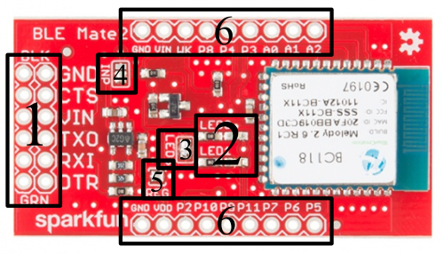
GPS Shield Hookup Guide

$
0
0

GPS Shield Hookup Guide a learn.sparkfun.com tutorial

Available online at: http://sfe.io/t17

Introduction

The SparkFun GPS shield has several convenient features that make it easy to use GPS modules with the Arduino Uno and SparkFun RedBoard (or any development board that supports the Arduino shield form factor).

alt text

A GPS Shield sporting a UP501 GPS module, atop an Arduino Uno.

Assembly

Before use, you will need to solder headers to your shield. Take a look at the Shield Assembly tutorial if you need a refresher. The GPS Shield uses the Uno R1 footprint with 2x 8-pin and 2x 6-pin headers.

alt text

Required Materials

The GPS Shield Kit comes with the shield, headers, an EM-506 GPS module andfoam tape for attaching the module to the shield.

If you purchased the GPS shield separately, you will need to acquire a GPS Module of your choice as well as the corresponding cables, headers or other connectors.

Suggested Reading

If you haven’t worked with GPS before, you may want to read the following tutorials before continuing with the GPS Shield.

  • GPS Basics - If you’ve always wanted to know how GPS works, this is the tutorial for you.

If you’re not using Arduino or another microcontroller, you can still view the GPS module’s serial output (and send commands to the GPS) using a terminal program.

Shield Overview

The top of the GPS shield:

alt text

and the bottom:

alt text

The SparkFun GPS Shield includes a 6-pin JST-SH socket (labeled EM406 on the top) that fits both the EM-506 (included with the GPS shield kit) and its discontinued predecessor the EM-406A as well as the the GP-635T. There are exposed pins and a small prototyping area for use with other GPS modules. And there are unpopulated pads for the 5-pin JST-SH connector found on the discontinued EM-408 module (labeled EM408 on the top) .

The UART/DLINE switch connects the GPS module’s serial lines to either Arduino hardware serial (D0/RX and D1/TX) or a user-selectable pair of software serial pins (D2 and D3 by default).

The closed solder jumpers marked Dselect 2 and 3 determine which pins are used in DLINE mode.

The ON/OFF switch controls power to the GPS module. The RESET button connects to the Arduino underneath.

On the back of the shield, there is an unpopulated 12mm coin cell battery holder footprint for adding battery backup and warm start capabilities.

There is an additional unpopulated footprint for an 8-pin JST-SH connector as seen on the discontinued 85A GPS module.

The BATT/3.3V jumper connects the VBAT lines on the unpopulated JST connectors to either the (unpopulated) backup battery or to the Arduino’s 3.3V line. 3.3V is selected by default.

Code Example

For this example, you will need to install the TinyGPSPlus library. Take a look at our Arduino library install tutorial if you’ve never installed an Arduino library before.

Download TinyGPSPlus Library

Mikal Hart’s Arduiniana.org has a full overview of all of the capabilities of the TinyGPS++ library, but the most important one is parsing the GPS module’s NMEA sentence output into latitude and longitude.

Press your completed Arduino shield (with headers soldered and your GPS plugged in or soldered on) onto your Arduino, and connect your Arduino to your computer with your USB cable.

You will be using software serial for this example, so leave the switch in DLINE.

Upload the example sketch below to your Arduino.

language:c
#include <TinyGPS++.h>
#include <SoftwareSerial.h>
/*
 This example uses software serial and the TinyGPS++ library by Mikal Hart
 Based on TinyGPSPlus/DeviceExample.ino by Mikal Hart
 Modified by acavis
*/

// Choose two Arduino pins to use for software serial
// The GPS Shield uses D2 and D3 by default when in DLINE mode
int RXPin = 2;
int TXPin = 3;

// The Skytaq EM-506 GPS module included in the GPS Shield Kit
// uses 4800 baud by default
int GPSBaud = 4800;

// Create a TinyGPS++ object called "gps"
TinyGPSPlus gps;

// Create a software serial port called "gpsSerial"
SoftwareSerial gpsSerial(RXPin, TXPin);

void setup()
{
  // Start the Arduino hardware serial port at 9600 baud
  Serial.begin(9600);

  // Start the software serial port at the GPS's default baud
  gpsSerial.begin(GPSBaud);

  Serial.println(F("DeviceExample.ino"));
  Serial.println(F("A simple demonstration of TinyGPS++ with an attached GPS module"));
  Serial.print(F("Testing TinyGPS++ library v. ")); Serial.println(TinyGPSPlus::libraryVersion());
  Serial.println(F("by Mikal Hart"));
  Serial.println();
}

void loop()
{
  // This sketch displays information every time a new sentence is correctly encoded.
  while (gpsSerial.available() > 0)
    if (gps.encode(gpsSerial.read()))
      displayInfo();

  // If 5000 milliseconds pass and there are no characters coming in
  // over the software serial port, show a "No GPS detected" error
  if (millis() > 5000 && gps.charsProcessed() < 10)
  {
    Serial.println(F("No GPS detected"));
    while(true);
  }
}

void displayInfo()
{
  Serial.print(F("Location: "));
  if (gps.location.isValid())
  {
    Serial.print(gps.location.lat(), 6);
    Serial.print(F(","));
    Serial.print(gps.location.lng(), 6);
  }
  else
  {
    Serial.print(F("INVALID"));
  }

  Serial.print(F("  Date/Time: "));
  if (gps.date.isValid())
  {
    Serial.print(gps.date.month());
    Serial.print(F("/"));
    Serial.print(gps.date.day());
    Serial.print(F("/"));
    Serial.print(gps.date.year());
  }
  else
  {
    Serial.print(F("INVALID"));
  }

  Serial.print(F(""));
  if (gps.time.isValid())
  {
    if (gps.time.hour() < 10) Serial.print(F("0"));
    Serial.print(gps.time.hour());
    Serial.print(F(":"));
    if (gps.time.minute() < 10) Serial.print(F("0"));
    Serial.print(gps.time.minute());
    Serial.print(F(":"));
    if (gps.time.second() < 10) Serial.print(F("0"));
    Serial.print(gps.time.second());
    Serial.print(F("."));
    if (gps.time.centisecond() < 10) Serial.print(F("0"));
    Serial.print(gps.time.centisecond());
  }
  else
  {
    Serial.print(F("INVALID"));
  }

  Serial.println();
}

Open your Arduino serial terminal by going to Tools > Serial Monitor

alt text

Latitude, longitude, and time stamp values should be streaming by! You’ll never get lost in front of your computer again!

Using the GPS Breakout

If you are using a smaller Arduino like the Pro Mini you can use a GPS Breakout instead of the GPS shield, though your selection of compatible modules is smaller than it is with the shield.

alt text

Troubleshooting

“No GPS Detected” error

If you’re using the EM-506 GPS from the GPS Shield Kit, make sure the JST-SH cable is firmly seated on both the module side and on the shield’s socket.

Check that the serial select switch is in DLINE

Check that the shield’s power switch is ON

If you’re using an Arduino based on a chip other than the ATMega328, make sure you are using a pair of software-serial compatible pins.

“INVALID” location, date, and time

Location: INVALID Date/Time: INVALID INVALID
Give your GPS some time to get a fix. The EM-506 module shows a solid red light for no fix and flashes when the fix is successful.

If your module fails to get a fix after several minutes, try moving closer to a window or even outside. In severe cases, such as in an urban canyon or inside a building with heavy concrete floors and ceilings, you may have to completely change locations.

Resources and Going Further

Check out these other GPS related tutorials.


learn.sparkfun.com |CC BY-SA 3.0 | SparkFun Electronics | Niwot, Colorado

SparkFun Blocks for Intel® Edison - Arduino Block

$
0
0

SparkFun Blocks for Intel® Edison - Arduino Block a learn.sparkfun.com tutorial

Available online at: http://sfe.io/t276

Introduction

The Arduino Block for Edison provides the Intel® Edison with a direct, serial link to an Arduino-compatible ATmega328 microprocessor.

Arduino Block iso

Why would you need an Arduino connected to your Edison? Isn’t it powerful enough to handle anything that may be thrown at it? That’s the problem – it’s almost too powerful. Because it’s running an operating system, it’s incapable of real-time processing – the bread-and-butter of smaller microcontrollers like the ATmega328. Components which require precise timing – like WS2812 LEDs or servo motors– may be incompatible with the Edison as it can’t reliably generate clock signals.

The Arduino block allows the Edison to offload those lower-level hardware tasks. Additional to that, if you’ve already written Arduino code for an external component, you don’t have to port that code to the Edison – just run it on an Arduino block!

Suggested Reading

If you are unfamiliar with Blocks, take a look at the General Guide to Sparkfun Blocks for Intel Edison.

Other tutorials that may help you on your Arduino Block adventure include:

Board Overview

Annotated diagram of Arduino Block

  • Expansion Header– The 70-pin Expansion header breaks out the functionality of the Intel Edison. This header also passes signals and power throughout the stack. These function much like an Arduino Shield.
  • Arduino I/O Pins– All of the Arduino’s I/O pins are broken out to a pair of headers (plus a couple in between). This header footprint exactly matches that of the Arduino Pro Mini– if you have any Mini shields they should mate exactly to this header.
  • Arduino Programming Header– The standard 6-pin FTDI header is used to program the Arduino’s serial bootloader. Plug a 3.3V FTDI Basic in to program your Arduino.
  • D13 LED– Every good Arduino needs an LED! This small, green LED is tied to the Arduino’s pin 13. Great for blinking “Hello, world” or debugging.
  • Power LED– The Arduino block has an on-board 3.3V regulator, and this LED is tied to the output of that regulator.
  • Arduino Reset Button– This reset button is tied to the Arduino’s reset line. It will only reset the Arduino; it has no effect on the Edison.

Schematic Overview

The Arduino block pairs the ATmega328 to your Edison via one of two UARTs. The board defaults to connecting the Arduino to Edison via UART1. Jumpers (see more below) allow you to select UART2, if your application requires. Take care using UART2, though, it’s default utility is for console access to the Edison.

The Arduino Block has an on-board 3.3V voltage regulator, which takes its input from the Edison’s VSYS bus. Since the Arduino is running at 3.3V, its clock speed is limited to 8MHz.

If you want to take a closer look at the schematic, download the PDF here.

Jumpers

On the back-side of the Arduino block, there are a handful of jumpers, which lend extra utility to the board.

Arduino Block Jumpers

Three two-way jumpers – for RX, TX, and DTR – allow you to select between UART1 (default) and UART2. To switch these jumpers, grab a hobby knife, cut the default traces, and drop a solder blob between the middle pad and outer pad of your choice.

The jumper labeled VIN/VSYS allows you to remove the VSYS line from powering the Arduino block. This is handy if you need to isolate the Arduino block’s power source from the Edison. In this case, you’ll need to supply power (3.3-12V) externally via the “VIN” pin.

Using the Arduino Block

To use the Arduino Block, attach it to either an Edison or add it to a stack of other SparkFun Block’s.

Arduino Block in a stack

Arduino block stacked on top of a GPIO Block and a Base Block.

In order to supply power to your Edison, you’ll need at least one additon Block in your stack. You can use a Base Block or Battery Block, for example.

Programming the Arduino

The Arduino on the Arduino Block can be programmed while it’s either on or off the Edison. Depending on your application, though, it’s recommended that you load code on the Arduino while it’s disconnected from your Edison stack, before adding it to the rest of the system.

If you’ve ever uploaded an Arduino sketch to an Arduino Pro or Pro Mini, you’re already familiar with uploading code to the Arduino block. Connect a 3.3V FTDI Basic to the 6-pin FTDI header on the board.

Programming the Edison block

Using a 3.3V FTDI Basic to program the Arduino on the Arduino Block.

In Arduino (the non-Edison version of Arduino!), select “Arduino Pro or Pro Mini 3.3V/8MHz” from the Tools > Board menu. If you’re using the latest release of Arduino (1.6 or later), first select Arduino Pro or Pro Mini from the “Board” menu.

Board selection

Then select ATmega328 (3.3V, 8MHz) from the “Processor” menu.

Processor selection

Then upload away!

Using the Arduino Pins

The Arduino’s I/O pins are all broken out to a pair of headers. These headers match up exactly to the Arduino Pro Mini. If you have any shields or piggyback boards for a Pro Mini, it should work seamlessly with the Arduino Block.

You can solder headers, wires, or any other connectors to these pins.

Arduino Block in action

If you’re soldering headers to the pins, take extra care deciding which side to solder to. Depending on the rest of your Edison stackup, those headers might get in the way of connectors on other boards (the USB connectors on the Base and Console Blocks, in particular).

Connecting the Edison to the Arduino

The Arduino Block connects the Arduino to the Edison through a serial (UART) connection. Jumpers on the back of the board allow you select which of the Edison’s two UARTs mate with the Arduino. Unless you can’t avoid it, we recommend leaving the jumpers in the default configuration – the Edison’s UART2 is usually devoted to console access.

To program the Edison to control and interact with the Arduino, you’ll need to use the UART to establish a communication protocol between the devices. See the next section for an easy example of UART communication between Arduino and Edison.

Controlling the Arduino Block with Firmata

Firmata is an established protocol popular within the Arduino realm for applications that require a separate machine (usually a computer) to control the Arduino. It’s a serial-based protocol that uses defined messages to set digital pins, read analog pins, and do everything else you’re used to with Arduino.

Firmata is so useful, the standard Arduino IDE even ships with the Firmata library. Here’s an example of how an Edison can be used to control and interact with an Arduino running Firmata.

Upload StandardFirmata to the Arduino

Before uploading any code to the Edison, let’s load something into the Arduino. Once the Firmata code is running on your Arduino, you may never have to upload code to it again.

Using the standard Arduino IDE (i.e. not the IDE built for Edison), load up the “StandardFirmata” sketch by going to File>Examples>Firmata>StandardFirmata. If you have the Codebender addon installed, you can use the embed below to upload the code to your Arduino Block.

With the Firmata firmware uploaded, you can disconnect the FTDI Basic, and connect the Arduino Block to your Edison stack.

Edison Firmata for Arduino Client

The harder part of this equation is writing something that executes on the Edison which interacts with our Firmata-running Arduino. There are tons of great client examples in the Firmata GitHub profile, but nothing quite built for the Edison.

Riffing on the Firmata Processing example, we wrote this sketch to enact an Edison Firmata client.

Arduino version alert! This Arduino sketch is intended to run on the Edison. You'll need to download the Edison Arduino IDE, and use that to upload this code to your Edison. For more help programming the Edison in Arduino, check out our Getting Started with Edison tutorial.

Here’s the sketch. Copy/paste from below, or grab the latest version from this Gist:

language:c
/****************************************************************
   Edison Firmata Client
   by: Jim Lindblom @ SparkFun Electronics
   created on: Februrary 12, 2015
   github:

   This is an Firmata client sketch for the Edison. It can
   communicate with an Arduino running Firmata over a Serial
   connection.

   Support for the following functions is written:
     firmata_init() -- set up firmata and pin reporting
     firmata_pinMode([pin], [0, 1, 2, 3, 4, 5, 6])
     firmata_digitalWrite([pin], [LOW/HIGH])
     firmata_analogWrite([pin], [0-255])
     firmata_analogRead([0-7])
     firmata_digitalRead([pin])
     firmata_servoWrite([pin], [value])

   Development Environment Specifics:
   Arduino 1.5.3 (for Edison)
   Intel Edison rev C
   Arduino Block for Edison
     Arduino should be running StandardFirmata

   This sketch is based on Firmata's processing client:
   https://github.com/firmata/processing
   As such, it is released under the same, free license. You can
   redistribute it and/or modify it under the terms of the GNU
   Lesser General Public License as published by the Free
   Software Foundation; either version 2.1 of the License, or
   (at your option) any later version.

   Distributed as-is; no warranty is given.
****************************************************************/
// SerialEvent1 isn't defined in the Edison core (I think).
// To get some form of interrupt-driven Serial input, we'll read
// serial in on a timer.
#include <TimerOne.h>

#define MAX_DATA_BYTES 4096
#define MAX_PINS 128

// Pin Mode definitons:
// Use any of these six values to set a pin to INPUT, OUTPUT,
// ANALOG, PWM, SERVO, SHIFT, or I2C.
enum const_pin_mode {
  MODE_INPUT,  // 0
  MODE_OUTPUT, // 1
  MODE_ANALOG, // 2
  MODE_PWM,    // 3
  MODE_SERVO,  // 4
  MODE_SHIFT,  // 5
  MODE_I2C     // 6
};

// Message Types
// Used by the low-level Firmata functions to set up the
// Firmata messages.
#define ANALOG_MESSAGE  0xE0
#define DIGITAL_MESSAGE 0x90
#define REPORT_ANALOG   0xC0
#define REPORT_DIGITAL  0xD0
#define START_SYSEX     0xF0
#define SET_PIN_MODE    0xF4
#define END_SYSEX       0xF7
#define REPORT_VERSION  0xF9
#define SYSTEM_RESET    0xFF

// Extended Commands:
// Used by the low-level Firmata functions to set up the
// Firmata messages.
#define SERVO_CONFIG            0x70
#define STRING_DATA             0x71
#define SHIFT_DATA              0x75
#define I2C_REQUEST             0x76
#define I2C_REPLY               0x77
#define I2C_CONFIG              0x78
#define EXTENDED_ANALOG         0x6F
#define PIN_STATE_QUERY         0x6D
#define PIN_STATE_RESPONSE      0x6E
#define CAPABILITY_QUERY        0x6B
#define CAPABILITY_RESPONSE     0x6C
#define ANALOG_MAPPING_QUERY    0x69
#define ANALOG_MAPPING_RESPONSE 0x6A
#define REPORT_FIRMWARE         0x79
#define SAMPLING_INTERVAL       0x7A
#define SYSEX_NON_REALTIME      0x7E
#define SYSEX_REALTIME          0x7F

// Flags and variables to keep track of message reading status:
boolean parsingSysex = false;
int waitForData = 0;
int storedInputData[MAX_DATA_BYTES];
int sysexBytesRead = 0;
int executeMultiByteCommand = 0;
int multiByteChannel = 0;
// Variable arrays to keep track of pin values read in.
int digitalInputData[] = {0, 0, 0, 0, 0, 0, 0, 0,
                          0, 0, 0, 0, 0, 0, 0, 0};
int analogInputData[] = {0, 0, 0, 0, 0, 0, 0, 0,
                         0, 0, 0, 0, 0, 0, 0, 0};
int analogChannel[MAX_PINS];
boolean blinkFlag = false;

void setup()
{
  // Debug messages are sent out Serial. Use the Serial monitor
  // at 9600 bps to read pin values.
  Serial.begin(9600);

  // firmata_init sets up our firmata client. It tells the
  // Firmata device to begin streaming analog values and any
  // digital pin value changes.
  firmata_init();

  // Use firmata_pinMode([pin], [value]) to set up pins on the
  // Firmata host:
  firmata_pinMode(13, MODE_OUTPUT); // LED tied to pin 13
  firmata_pinMode(4, MODE_INPUT);   // Digital input on pin 4
  firmata_pinMode(A0, MODE_ANALOG); // Analog input on pin 0
  firmata_pinMode(3, MODE_PWM);     // PWM LED on pin 3
}

void loop()
{
  // Print the value of our Firmata Arduino's A0 pin:
  int a0Value = firmata_analogRead(0);
  Serial.print("A0: ");
  Serial.println(a0Value);


  // Print the value of our digital input on pin 4:
  int d4Value = firmata_digitalRead(4);
  Serial.print("Pin 4: ");
  Serial.println(d4Value);

  if (d4Value == LOW)
  {
    // Scale the value of A0 to write a PWM output on pin 3:
    firmata_analogWrite(3, firmata_analogRead(0) / 4);
  }
  else
  {
    // Scale the value of A0 to write a PWM output on pin 3:
    firmata_analogWrite(3, 0);
  }

}

///////////////////////////////////
// Upper Level Firmata Functions //
///////////////////////////////////
// Firmata functions that you should use in your sketch above.
// If this was a class, these'd be public functions.

// firmata_init() --
// - Initialize our Firmata Serial port.
// - Set up a timer to read in Serial messages outside of loop().
// - Configure our Firmata Arduino to report all digital outputs
// - Configure our Firmata Arduino to report all analog outputs
void firmata_init()
{
  Serial1.begin(57600);
  // set a timer of length 100,000 microseconds ( 0.1 sec - or 10Hz)
  Timer1.initialize(1000);
  Timer1.attachInterrupt( checkSerial ); // attach the service routine here

  // Turn on reporting for all digital ports
  for (int i=0; i<16; i++)
  {
    Serial1.write(REPORT_DIGITAL | i);
    Serial1.write(1);
  }
  // This function will check for analog channels and set them
  // to REPORTING
  firmata_queryAnalogMapping();
}

// firmata_digitalRead([pin]) --
// - Returns the latest digital input value we've read on the
//   requested pin.
// - digitalInputData[] is updated in firmata_processInput()
//   as serial messages come in.
int firmata_digitalRead(int pin)
{
  return (digitalInputData[pin >> 3] >> (pin & 0x07)) & 0x01;
}

// firmata_analogRead([pin])
// - Returns the latest analog value we've read on the requested
//   pin.
// - analogInputData[] is updated in firmata_processInput()
//   as serial messages come in.
int firmata_analogRead(int pin)
{
  return analogInputData[pin];
}

// firmata_pinMode([pin], [mode])
// - Set an Arduino pin to input, output, analog in, PWM, servo,
//   shift register, or i2c.
// - [pin] - can be any Arduino pin 0-13, A0-A7
// - [mode] - should be one of these defined values:
//          - MODE_INPUT  - Digital input
//          - MODE_OUTPUT - Digital output
//          - MODE_ANALOG - Analog input
//          - MODE_PWM    - Analog output
//          - MODE_SERVO  - Servo output
//          - MODE_SHIFT  - Shift register output
void firmata_pinMode(int pin, int mode)
{
  Serial1.write(SET_PIN_MODE);
  Serial1.write(pin);
  Serial1.write(mode);
}

// firmata_digitalWrite([pin], [value])
// - Set an Arduino digital pin to HIGH or LOW
// - [pin] - Any digital pin 0-18
// - [value] - LOW or HIGH
void firmata_digitalWrite(int pin, int value)
{
  int port = (pin >> 3) & 0x0F;
  int data;

  if (value)
    data |= (1 << (pin & 0x07));
  else
    data &= ~(1 << (pin & 0x07));

  Serial1.write(DIGITAL_MESSAGE | port); // Digital data
  Serial1.write(data & 0x7F); // Digital pins 0-6 bitmask
  Serial1.write(data >> 7);   // Digital pin 7 bitmask
}

// firmata_analogWrite([pin], [value])
// - Set an Arduino pin - CONFIGURED AS PWM (!) - to an
//   analog output value.
// - [pin] - Any analog output capable pin (3, 5, 6, 9, 10, 11
// - [value] - 0-255
void firmata_analogWrite(int pin, int value)
{

  Serial1.write(ANALOG_MESSAGE | (pin& 0x0F)); // Analog pin
  Serial1.write(value & 0x7F); // Analog LS 7 bits
  Serial1.write(value >> 7);   // Analog MS 7 bits
}

// firmata_servoWrite([pin], [value])
// - Set an Arduino pin - CONFIGURED AS SERVO (!) - to output
//   a servo signal.
void firmata_servoWrite(int pin, int value)
{
  Serial1.write(ANALOG_MESSAGE | (pin & 0x0F));
  Serial1.write(value & 0x7F);
  Serial1.write(value >> 7);
}

/////////////////////////////////
// Low level Firmata functions //
/////////////////////////////////
// Firmata helper functions you probably won't need to call in
// your sketch. If this was a class, these'd be private functions.

// checkSerial()
// Interrupt-recurring function. Checks for available serial data
// and processes any serial messages that come in.
void checkSerial()
{
  while (Serial1.available())
  {
    //Serial.write(Serial1.read());
    firmata_processInput((unsigned char) Serial1.read());
  }
  if (blinkFlag)
  {
    firmata_digitalWrite(13, HIGH); // Tell Arduino to write 13 HIGH
    blinkFlag = false;
  }
  else
  {
    firmata_digitalWrite(13, LOW); // Tell Arduino to write 13 HIGH
    blinkFlag = true;
  }
}

// firmata_processInput([inputData])
// Handles all Firmata messages - everything from version checks
// to analog and digital readings.
void firmata_processInput(unsigned char inputData)
{
  int command;

  if (parsingSysex) // If we're parsing a system message
  {
    if (inputData == END_SYSEX)
    { // Received end of system message, process it
      parsingSysex = false;
      firmata_processSysexMessage();
    }
    else
    { // In the system message, add to it
      storedInputData[sysexBytesRead] = inputData;
      sysexBytesRead++;
    }
  }
  else if (waitForData > 0 && inputData < 128)
  { // Else waiting for data
    waitForData--; // Decrement wait for data
    storedInputData[waitForData] = inputData;

    if (executeMultiByteCommand != 0 && waitForData == 0)
    {
      switch(executeMultiByteCommand)
      {
      case DIGITAL_MESSAGE:
        firmata_setDigitalInputs(multiByteChannel,
                 (storedInputData[0] << 7) + storedInputData[1]);
        break;
      case ANALOG_MESSAGE:
        firmata_setAnalogInput(multiByteChannel,
                 (storedInputData[0] << 7) + storedInputData[1]);
        break;
      case REPORT_VERSION:
        firmata_setVersion(storedInputData[1], storedInputData[0]);
        break;
      }
    }
  }
  else // Beginning of a message
  {
    if (inputData < 0xF0)
    {
      command = inputData & 0xF0;
      multiByteChannel = inputData & 0x0F;
    }
    else
    {
      command = inputData;
    }
    switch (command)
    {
    case DIGITAL_MESSAGE:
    case ANALOG_MESSAGE:
    case REPORT_VERSION:
      waitForData = 2;
      executeMultiByteCommand = command;
      break;
    case START_SYSEX:
      parsingSysex = true;
      sysexBytesRead = 0;
      break;
    }
  }
}

// firmata_processSysexMessage()
// - Process a system message.
// - Mostly just handles defining which pins are analog channels.
void firmata_processSysexMessage()
{
  switch (storedInputData[0])
  {
  case ANALOG_MAPPING_RESPONSE:
    // Begin by setting every channel to NOT analog (127)
    for (int pin = 0; pin < sizeof(analogChannel); pin++)
      analogChannel[pin] = 127;
    // Enumerate analog channels:
    for (int i = 1; i < sysexBytesRead; i++)
      analogChannel[i - 1] = storedInputData[i];
    // Set each analog output to reporting
    for (int pin = 0; pin < sizeof(analogChannel); pin++)
    {
      if (analogChannel[pin] != 127)
      {
        Serial1.write(REPORT_ANALOG | analogChannel[pin]);
        Serial1.write(1);
      }
    }
    break;
  }
}

// firmata_queryAnalogMapping()
// - Send the ANALOG_MAPPING_QUERY request message.
// - Called in init to keep track of which pins are analog ins
void firmata_queryAnalogMapping()
{
  Serial1.write(START_SYSEX);
  Serial1.write(ANALOG_MAPPING_QUERY);
  Serial1.write(END_SYSEX);
}

// firmata_setDigitalInputs()
// - Set a value in the digitalInputData array to portData
void firmata_setDigitalInputs(int portNumber, int portData)
{
  digitalInputData[portNumber] = portData;
}

// firmata_setAnalogInput
// - Set an analog pin value to [value].
void firmata_setAnalogInput(int pin, int value)
{
  analogInputData[pin] = value;
}

void firmata_setVersion(int majorVersion, int minorVersion)
{
  //! Todo
}

After uploading that sketch to your Edison, your Arduino Block should begin blinking the D13 pin. You can also open up the Serial Monitor to see what values your Arduino Block is reading in on D4 and A0.

This serves as a simple Firmata client for the Edison, but it should be easily expandable. Try using any of these functions (defined in lower portions of the sketch) to add more features to your Edison Firmata Client:

  • firmata_pinMode([pin], [mode])– As with any Arduino sketch, setting the pin’s mode is critical. Firmata requires an extra bit of information. Use any Arduino pin for the [pin] variable. For the [mode] variable use either MODE_INPUT, MODE_OUTPUT, MODE_ANALOG, MODE_PWM, MODE_SERVO, or MODE_SHIFT.
  • firmata_digitalRead([pin])– Read in the digital value of a pin. This function will return a value between 0 and 1. That pin should be set as MODE_INPUT before calling this function.
  • firmata_analogRead([pin])– Read in the value of an anlog pin. This function will return a value between 0 and 1023. The pins should be set as MODE_ANALOG before being read.
  • firmata_digitalWrite([pin], [value])– Write a digital pin either HIGH or LOW. The pin should be set as MODE_OUTPUT before calling the function.
  • firmata_analogWrite([pin], [value])– Write an analog-output pin to a value between 0 and 255. The pin must be PWM-capable – that means either pin 3, 5, 6, 9, 10, or 11. And it should be configured as a MODE_PWM before hand.
  • firmata_servoWrite([pin], [value])–Set a pin to output a servo signal. The value here is an angle between 0 and whatever the high-end angle of your servo is. Remember to set the pin to MODE_SERVO before calling this function!

Don’t feel like you have to user Firmata when using the Arduino block with your Edison. It’s a great place to start, though, if you’re looking for a simple communication protocol over the serial interface.

Resources and Going Further

Now that you have had a brief overview of the Arduino Block, take a look at some of these other tutorials. These tutorials cover programming, Block stacking, and interfacing with the Intel Edison ecosystems.

Edison General Topics:


learn.sparkfun.com |CC BY-SA 3.0 | SparkFun Electronics | Niwot, Colorado
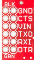
E-Textile Art Pin

$
0
0

E-Textile Art Pin a learn.sparkfun.com tutorial

Available online at: http://sfe.io/t347

Introduction

Let’s create a quick and easy piece of e-textile art using a LilyPad LED, battery holder, conductive thread, and coin cell battery. This beginner project introduces sewing with conductive thread to create a simple circuit pin.

This is also one of our most popular activities for large ‘make and take’ events, so we’ve included downloadable templates for use with inkjet printable fabric if you want to save time. The attached PDFs are available in full color or black and white coloring book style designs.

alt text

Suggested Reading

If you’ve never worked with e-textiles before, you may want to have a look at these other tutorials.

Materials and Tools

Let’s go over all of the things you’ll need to sew your project together:

alt text

Note - LilyPad LEDs are sold in packs of five; you’ll only need one for this project.

You will also need:

  • Fabric - to draw your design on (or printable fabric if you are downloading our designs). Canvas or muslin work well.
  • Felt - cut into a 2.5" circle
  • Scissors
  • Hot glue gun
  • Fabric Markers
  • Pin Back - Rectangular adhesive ones work well.
  • Optional - printer if you are using our designs.

Step 1: Prepare Fabric

Cut a 2.5" circle of felt for the backing of your pin and a slightly larger circle out of thin fabric for the front/top of your pin. If your fabric is fraying along the edges, use fray check or clear nail polish to seal after you finish your project.

Designs

Here are some designs we’ve created. There are 12 to a sheet, but you’ll only need one for this project. Right-click the image below and choose “Save Link As” to download the design to your computer.

Full Color Pin Designs

alt text

Black and White Pin Designs

alt text

After downloading a design, follow the directions on the package of your printable fabric to print them out. Feel free to create a larger pin by scaling the downloadable designs if you’d like more room to work with or for a real statement piece.

Tip: do a test print on plain paper before using the fabric.

Step 2: Attach Components

Take a look at your LED and battery holder, and notice that the silver sewing holes are labeled either positive or negative. Orient the battery holder with the ON/OFF switch to the left side and the bottom of the holder as close to the edge as you can. Use a a small dot of hot glue in the center of the holder to attach it to the felt, as shown. Gluing the battery holder on this way leaves room for the LilyPad LED.

alt text

Placing LED

Flip the circle over – time to decide on the placement of the LED.

If you are using one of the pre-made designs, hold the design over the felt, and use a fabric marker to mark where the LED should be placed to shine through. Be careful not to put the LED directly behind the battery holder or else you won’t be able to sew through it.

If you are designing your own artwork, decide where on the fabric the LED should shine through, and mark it. Draw your design now, or wait until the finishing touches step.

alt text

While designing, keep in mind that the LED will need to be slightly above the center or towards the top half of the fabric so it doesn’t interfere with the battery holder.

alt text

Grab an LED, and line up the (+) and (-) symbols with the symbols on the battery holder. Remember, we are working on the opposite side of the felt, so the symbols will be reversed.

Use a small dab of hot glue in the middle of the board to secure to the felt. Be careful not to cover the holes with glue -– we’ll need those to sew through later. Do not put your battery in yet.

alt text

Step 3: Sew Positive Trace

After you’ve arranged your components, it’s time to sew them together! We’ll be sewing paths for the electricity, called traces, with conductive thread, connecting the positive (+) sides of the components together, and then the same for the negative (-) sides. Unwind about 1 foot of conductive thread to work with, carefully thread the needle, and tie a knot at the end. A needle threader or needle with a larger eye will help, if you are having trouble getting the thread through. Just be careful not to use a needle too big for the holes in your LilyPad components.

alt text

On your battery holder, find the hole marked with a positive (+) symbol closest to your LED board. Push your needle up through hole and felt, then to the outside of the hole and felt – this creates a stitch that holds the battery holder down and makes an electrical connection with the metal around the hole. Repeat 3 more times to make a secure connection, then, using a straight stitch, follow your path to the next positive hole on your LED. Don’t forget to loop 3-4 times around each hole to secure. Once you have finished at the LED, tie a knot in your thread, and trim any excess. Congratulations, you’ve just sewn the first half of your circuit!

alt text

alt text

Step 4: Sew Negative Trace

Tie a knot in your remaining thread (or cut a new piece if needed), then connect the negative side of your LED board to the negative holes of the battery holder using the same technique used for the positive trace. Be careful not to let your stitches touch the path you used for your positive connections. Now your circuit is complete!

alt text

alt text

Step 5: Test Your Circuit

Insert your coin cell battery with the positive side facing up (marked with a +), into your battery holder. The battery slides in the opening only one way (the side opposite of the on/off switch). Turn on the switch to see if your LED shines bright!

alt text

Troubleshooting

With any electronics project there are times you will have to troubleshoot if your circuit isn’t working. If your circuit isn’t lighting up, try a new battery or check that your switch is in the on position. Check your sewing for any loose threads or ends that may be touching other parts of your circuit and causing a short circuit. See the picture for examples of conductive thread short circuits –- practice tidy stitching to keep your thread from causing problems.

alt text

Step 6: Finishing Touches

Once your circuit is working, use a hot glue gun to attach your fabric design over your felt circle so the LED shines through. Turn the project over and attach an adhesive pin back to finish up your wearable art!

Tip: If you are using a metal pin back, make sure not to accidentally touch the metal on the battery holder or any of the conductive thread - it could cause a short circuit.

alt text

Here are some examples of finished pins:

alt text

alt text

alt text

Resources and Going Further

Thanks for reading! Practice your circuit sewing skills with one of these other projects:


learn.sparkfun.com |CC BY-SA 3.0 | SparkFun Electronics | Niwot, Colorado

Viewing all 1123 articles
Browse latest View live


<script src="https://jsc.adskeeper.com/r/s/rssing.com.1596347.js" async> </script>