Quantcast
Channel: SparkFun Tutorials
Viewing all 1123 articles
Browse latest View live

BadgerHack

$
0
0

BadgerHack a learn.sparkfun.com tutorial

Available online at: http://sfe.io/t349

Introduction

The Badger

What you hold in your hands is a powerful piece of technology. OK, it’s no tricorder, but it can do some pretty cool stuff. You can program the BadgerStick (the thin board) to control a myriad of electronics, like buttons, lights, and LCDs. The LED board can be used to display patterns or show text.

In the first section of this guide, we will show you how to solder headers on to your BadgerStick and LED board to make a complete badge.

Completed badge

On top of a sweet badge, you also get a development platform that you can use in lots of other projects. Once you have put your badge together, worn it with pride, and shown if off to everyone, you can remix it and make your own project!

The rest of the guide will focus on hacking your badge: how you can create your own graphics or add other electronics to make it do cool stuff.

Playing games on my BadgerStick

Suggested Reading

If you are new to soldering or electronics, we highly recommend you check out the following:

When you are ready to start hacking your badge, we definitely recommend reading:

Make Your Badge

Now that you have the Badger kit, let’s make a badge! When we ask you to solder a pin, you will want to keep a few tips in mind (click for larger image):

SparkFun Soldering Tips

If you need a refresher on how to solder, we recommend the How to Solder guide.

1. Solder the 8-pin male header to the LED board

Insert the 8-pin male header into the LED board with the pin ends facing out. Note that the pins are coming out of the top of the board (the side with the LEDs).

Put the male header into the LED board

Flip the board over and solder all the pins.

Solder the male header to the LED board

2. Solder the 8-pin female header to pins 2-9 on the BadgerStick

Insert the 8-pin female header into the holes labeled 2, 3, 4, 5, 6, 7, 8, 9 on the BadgerStick. Make sure that the pins are coming out of the top of the board (the side with all the electronics).

Put the female header into the BadgerStick

Flip the board over, and ensure that only the holes in the white box labeled “LED Array” are used. Solder all 8 pins.

Solder the female header to the BadgerStick

3. Solder the 3-pin female header to the game port on the BadgerStick

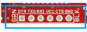
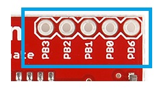
Insert the 3-pin female header into the holes labeled TX, GND, RX on the bottom of the board. The header should be coming out of the top of the board.

Put the 3-pin female header into the game port

Flip the board over, and solder all 3 pins.

Solder the 3-pin header to the BadgerStick

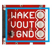
4. Solder the the red battery wire to the + battery pin (VBAT)

Poke the red battery wire through the backside of the BadgerStick on the pin labeled VBAT (“+” on the backside).

Red wire through the BadgerStick

Solder the red wire to the hole.

Solder the red wire

5. Solder the black battery wire to the - battery pin (GND)

Poke the black battery wire through the backside of the BadgerStick on the pin labeled GND (“-” on the backside).

Black wire through the BadgerStick

Solder the black wire to the hole.

Solder the black wire

Flip the BadgerStick over, and verify that the red wire is going to the hole labeled ‘+’ on the underside and that the black wire is going to the hole labeled ‘-’.

Battery wires going into the BadgerStick

6. Add batteries

Using a Phillips screwdriver, remove the screw from the battery pack.

Use a screwdriver to open the battery pack

Open the battery pack cover, and take note of the battery markings in the pack.

Markings in battery pack

Put the batteries in the pack as noted by the markings. The bumped end of the battery is + and the flat end is -.

Batteries in battery pack

Put the battery pack cover back on, and secure it with the screw.

Closed battery pack

7. Connect the LED board to the BadgerStick

Connect the LED board and BadgerStick, by sliding the headers together. Ensure the LEDs and electronics on the BadgerStick are facing the same direction.

Connected LED board to BadgerStick

Flip the boards over, and double-check your solder connections:

  • 8-pin male header soldered to the pins in the white box on the LED board
  • 8-pin female header soldered to the pins in the white box on the BadgerStick labeled “LED Array”
  • 3-pin female header soldered to the pins in the white box on the BadgerStick labeled “Game Port”
  • Red battery wire soldered to + Battery pin
  • Black battery wire soldered to the - Battery pin

Back of completed badge electronics

Before you stick your electronics to the badge, turn on the battery pack to make sure everything is working. Troubleshooting your board will be a lot easier if it’s not adhered to the badge.

8. Affix the components to the badge

Add one piece of double-sided foam tape to the LED board and another piece to the BadgerStick.

Add tape to LED board and BadgerStick

Add another two pieces of foam tape on top of the existing foam tape.

Add another layer of tape

Stick the LED board and BadgerStick to the front of the plastic badge.

Put electronics on badge

Put one more piece of foam tape on the battery pack on the side with the screw.

Tape on the battery pack

Stick the battery pack to the back of the plastic badge. To prevent the wires from hanging out, wrap them around the side of the badge as in the picture.

Battery pack on badge

9. Turn it on

Turn your badge over, and find the little switch on the battery pack. Flip it to “ON.”

Fire it up!

Flip your badge back over. Wait about 3 seconds, and you should see the LED matrix activate!

Light it up!

10. Badger it up!

You are now the proud owner of a SparkFun Badger badge! Attach a lanyard…

Attach a lanyard

…and wear it with pride.

Wearing the Badger

But that’s not all. The badge comes pre-loaded with a fun scavenger hunt. Read on, to learn how to play!

Play the Game

We have strategically placed 8 crystalline game stations in our partners' booths throughout SX Create and one “Alpha Station” in the LulzBot booth. Your job is to find them.

BadgerHack stations

These are the regular stations located throughout SX Create

Good news! You only have to find 4 of them. However, one of them must be the Alpha Station.

alt text

This is Alpha Station. You must visit this one.

How to Play

Once you have finished soldering your badge and turned it on, it’s time to play. First, visit the Alpha Station inside the LulzBot booth. Find the 3-pin game port on the station, and connect your badge’s game port (make sure your badge is facing up!).

Playing the game

Insert your badge face up into the station’s port

Now, you must hunt down 3 other stations. Visit any 3 of the booths with a station, and connect your badge to the game port to receive a point.

How to Win

You win when you have connected your badge to 4 unique Badger game stations (1 of them must be the Alpha Station). You receive no additional points or benefits for visiting more than 4 stations.

When you win, you will see an animation on your LED display. A coupon code will scroll across your screen 3 times. You can then use that coupon code at sparkfun.com (you can only use the code once, so use it wisely!). Make sure the code is 8 characters long.

Code scrolling across screen

You may now hold the badge high above your head, and let out a loud and victorious howl!

If you missed writing down the code, don’t worry! You can simply turn off your badge, and turn it back on again. If your badge has visited the 4 stations, it will scroll the code another 3 times. Every time you reset the badge, it will scroll the code 3 times.

Reset your badge to see the code again

Hack Your Badge

What do you do with your badge after the event? Well, you can hack it!

To program the BadgerStick, you will need the Arduino Integrated Development Environment (IDE). Find the section below about installing and configuring Arduino for your particular operating system (Windows, OS X, or Linux), and then move on to “Install Libraries.”

Install and Configure Arduino (Windows)

Download and Install Arduino

Download the latest Arduino IDE from arduino.cc or by clicking the button for Arduino 1.6.1.

Download Arduino 1.6.1

Double-click the downloaded executable, and follow the instructions to install Arduino.

Install COM Port Drivers

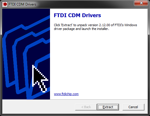
Navigate to FTDI’s Virtual COM Port drivers page, and click to download the “setup executable.”

Double-click on the executable to run it, and follow the prompts to install the Virtual COM Port drivers.

Extracting VCP drivers

Update boards.txt

We need to modify a file in the Arduino installation in order to work with the BadgerStick. Download the hardware files for BadgerStick support:

Download BadgerStick Support Files

Unzip and navigate to the folder BadgerStick_Support_Files/hardware/arduino/avr. Copy the boards.txt file.

Copy boards.txt

Paste them in <your Arduino installation folder>/hardware/arduino/avr, agreeing to overwrite/replace any existing files.

Paste boards.txt

That’s it! Move on to the “Install Libraries” section.

Install and Configure Arduino (OS X)

Install Java

If you do not have Java already installed, you will need it for Arduino. Go to Java for OS X 2014-001, and click the Download button.

Use Finder to navigate to your Downloads folder, and double-click the downloaded file to mount the image.

Download Java for OS X

Double-click the JavaForOSX.pkg file to run the installer.

Install Java for OS X

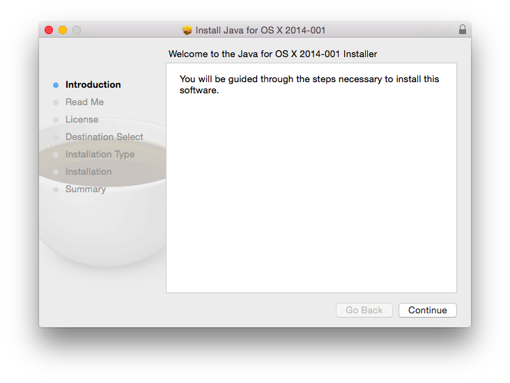
Follow the instructions to install Java 6.

Download and Install Arduino

Download the latest Arduino IDE from arduino.cc or by clicking the button for Arduino 1.6.1 (for Java 6).

Download Arduino 1.6.1

Locate the downloaded file in Finder and double-click it to extract the .zip file.

Unzip the Arduino application

Drag the newly unzipped Arduino application to the Applications folder.

Copy Arduino to the Applications folder

Install COM Port Drivers

Navigate to FTDI’s Virtual COM Port drivers page and click to download the latest version of the VCP drivers for Mac OS X x64 (64-bit).

Locate the downloaded driver file in Finder, and double-click it to mount the drivers as a disk image.

Mount COM drivers image

If you are on OS X 10.3, double-click the FTDIUSBSerialDriver_10_3. If you have a newer version of OS X, double-click the other installer. Follow the on-screen instructions to install the Virtual COM Port drivers.

Install COM drivers

If you run into an error like “can’t be opened because it is from an unidentified developer,” you will need to change your application security settings. See this post on how to do that.

Update boards.txt

We need to modify a file in the Arduino installation in order to work with the BadgerStick. Download the hardware files for BadgerStick support:

Download BadgerStick Support Files

Double-click the downloaded zip file to unzip it. Navigate to <your Downloads folder>/hardware/arduino/avr, and copy boards.txt.

Copy boards.txt

Right-click (or ctrl+click) on the Arduino application (in Applications), and select “Show Package Contents.” This will allow you to browse the files within the Arduino application.

Contents of the Arduino package

Navigate to Contents/Resources/Java/hardware/arduino/avr, and paste boards.txt. Agree to replace (overwrite) the existing boards.txt.

Paste boards.txt in the Arduino package

That’s it! Move on to the “Install Libraries” section.

Install and Configure Arduino (Linux)

Download and Install Arduino

Note that these steps were performed on Ubuntu 14.04. They might differ depending on your particular flavor of Linux.

Download the latest Arduino IDE from arduino.cc or by clicking the button for Arduino 1.6.0 (64-bit).

Download Arduino 1.6.1

Navigate to your Downloads directory, right click on the downloaded tar file, and select “Extract Here.”

Untar the Arduino download

If you try and run the Arduino application, you might get an error like “java: not found.” Additionally, you may not have avr-gcc installed. So, open a command window, and enter the following:

sudo apt-get install openjdk-6-jre avr-libc gcc-avr

Enter ‘y’ when asked to install the additional packages.

Update boards.txt

We need to modify a file in the Arduino installation in order to work with the BadgerStick. Download the hardware files for BadgerStick support:

Download BadgerStick Support Files

Unzip and navigate to the folder BadgerStick_Support_Files/hardware/arduino/avr. Copy the boards.txt file.

Copy boards.txt

Paste them in <your Arduino installation folder>/hardware/arduino/avr agreeing to overwrite/replace any existing files.

Paste boards.txt

Enable Double-Click to Run Application

To run the Arduino program, you can simply navigate to the downloaded (and extracted) directory, and run the arduino script:

cd ~/Downloads/arduino-1.6.0/
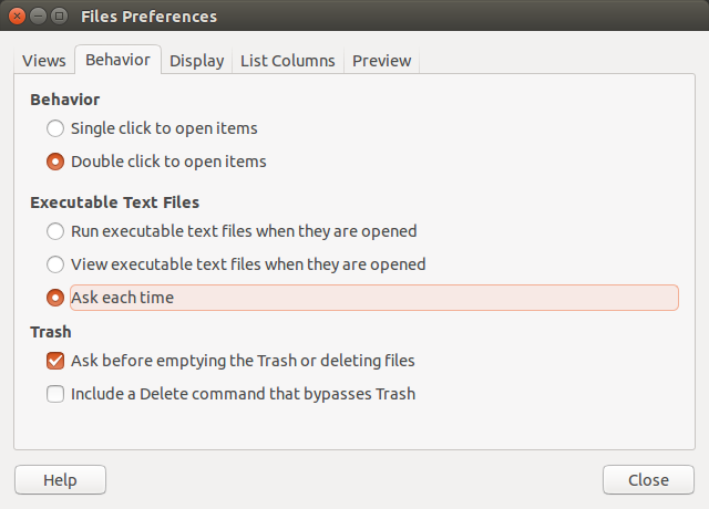
./arduino

To make the script run when you double-click it in a Files window, open up Files, go to Edit → Preferences.

Select preferences in Files

Go to the “Behavior” tab, and select “Ask each time.”

Select "Ask each time"

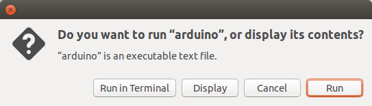
Close the Preferences window, and double-click the arduino script. You will be asked what to do. Select “Run” to start the Arduino application.

Choose to run the script

That’s it! Move on to the “Install Libraries” section.

Install Libraries

Now that the Arduino IDE is installed and configured, we need 2 important libraries for controlling the LED array. The following steps use screenshots from Windows, but the steps are the same for all operating systems.

Install the Chaplex Library

Charlieplexing is a slick way to control many LEDs with only a few input/ouptut (IO) pins. We rely on the Arduino Chaplex library to do much of this for us. Download the library to get started.

Download Chaplex Library

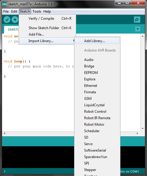
Run the Arduino IDE, and select Sketch → Import Library… → Add Library…

Add library in Arduino

Find the Chaplex.zip file you just downloaded, select it, and click open.

Install LED Array Library

We built a library on top of the Chaplex library that will let you draw shapes and text to the LED array with ease. Download that library here:

Download SparkFun_LED_8x7 Library

In the Arduino IDE, select Sketch → Import Library… → Add Library… Find the SparkFun_LED_8x7.zip file you just downloaded, select it, and click open.

Your First Badger Hack

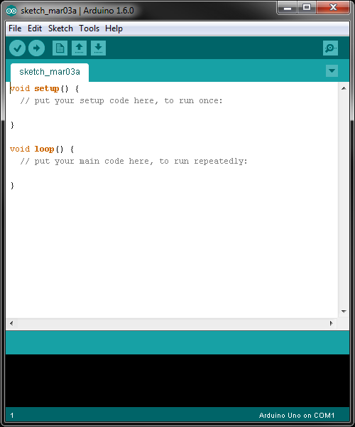
Plug your BadgerStick (with the LED array attached) into any available USB port on your computer. Open the Arduino IDE, and you will be presented with a template sketch.

Arduino template sketch

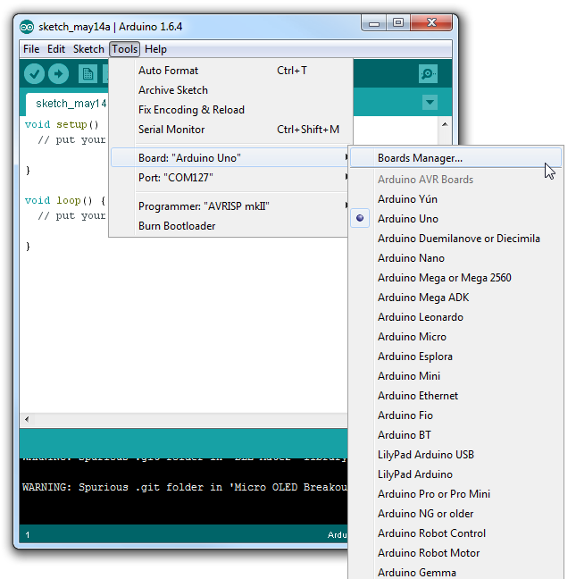
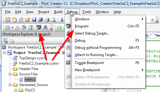
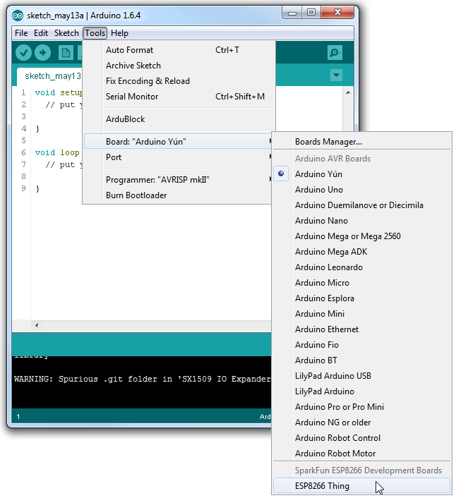
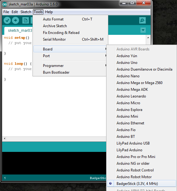
Go to Tools → Board, and select the BadgerStick (3.3V, 4 MHz).

Select BadgerStick Board

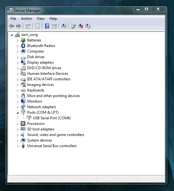
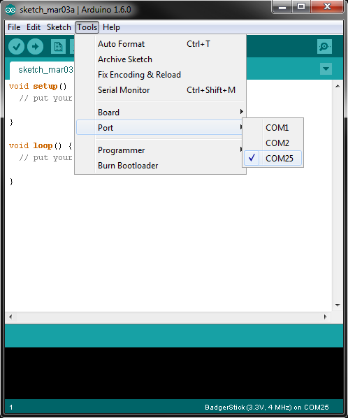
Go to Tools → Port, and select the COM port that is associated with your BadgerStick (e.g. COM25 in the example screenshot).

Select COM Port

Now, we get to write some code! In the Arduino IDE, copy in the following code:

language:c
#include <SparkFun_LED_8x7.h>
#include <Chaplex.h>

// Global variables
static byte led_pins[] = {2, 3, 4, 5, 6, 7, 8, 9}; // Pins for LEDs

void setup() {

  // Initialize LED array
  Plex.init(led_pins);

  // Clear display
  Plex.clear();
  Plex.display();
}

void loop() {

  // Scroll text 2 times
  Plex.scrollText("Hello world", 1);
  delay(7000);
  Plex.stopScrolling();
  delay(2000);
}

Notice that we had to include both the SparkFun_LED_8x7 library and Chaplex library in the code. We initialized the LED display (lovingly called “Plex”) and scroll the phrase “Hello world” across the screen once, wait 2 seconds, and repeat.

Press the “Upload” button in the top left of the Arduino IDE to compile and send the program to the BadgerStick. If you are asked to save the file, you can choose to save your current project, or just press “Cancel” to continue uploading (without saving).

Arduino upload button

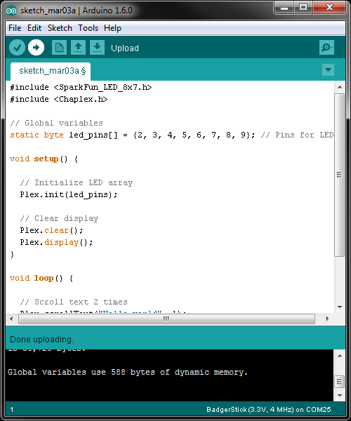
Wait while the IDE compiles and uploads the code. Once it finishes, you should see some pretty text scrolling across your LED array!

Hello world

Let’s make some shapes! The SparkFun_LED_8x7 library is also capable of creating basic shapes. Delete the code you have in the current Arduino window, and copy in the following:

language:c
#include <SparkFun_LED_8x7.h>
#include <Chaplex.h>

// Global variables
byte led_pins[] = {2, 3, 4, 5, 6, 7, 8, 9}; // Pins for LEDs
byte i;

void setup() {

  // Initialize and clear display
  Plex.init(led_pins);
  Plex.clear();
  Plex.display();
}

void loop() {

  // Clear the display buffer
  Plex.clear();

  // Draw a line (x0, y0, y1, y1)
  Plex.line(1, 4, 1, 6);

  // Draw a rectangle (x, y, width, height)
  Plex.rect(0, 0, 3, 3);

  // Draw a filled circle (x, y, radius)
  Plex.circleFill(5, 4, 2);

  // Display our shapes and wait a second before repeating
  Plex.display();
  delay(1000);
}

Upload the new code, and your LED board should show some fun shapes.

Make a Game

OK, so the display might be small (don’t get your hopes up of running Doom on an 8x7 monochrome display). However, we can use it to display information and even play some basic games.

Remember the game Breakout? I don’t, really, but the concept was cool. Let’s make a Breakout clone on our BadgerStick!

Hardware

Required Components

We will need a few other components to make a simple controller for the BadgerStick.

More Soldering

To begin, snap off 15 pins from the break-away headers, and solder them to the through-holes on the side opposite the LED array of the BadgerStick.

Solder pins to the BadgerStick

Solder the Thumb Joystick to the Thumb Joystick Breakout board.

Solder joystick to breakout board

Snap off 5 pins from the break-away headers, and solder them to the through-holes on the Joystick Breakout Board.

Solder pins to joystick breakout board

Connections

Place the BadgerStick in the breadboard with pin 10 in position i13 and pin 5V in position i27.

Connect the rest of the components as follows:

ComponentBreadboard
Thumb Joystick Breakout*i7 (VCC)i6 (VERT)i5 (HOR)i3 (GND)
Pushbuttonc20c22f20f22
Pushbuttonc28c30f28f30
Jumper Wire( - )g30
Jumper Wire( - )g25
Jumper Wire( - )g22
Jumper Wire( - )j3
Jumper Wirej7g23
Jumper Wirej6g18
Jumper Wirej5g17
Jumper Wireg21g28

* Pins not listed are not used.


Gaming badger

IMPORTANT: You can leave the battery pack soldered into the BadgerStick if you desire. If you remove the battery pack, you will need to supply power through another means, such as a USB port or a USB extension cable.

You should now have a makeshift game controller with a tiny LED screen!

Gaming badger with batteries

The Code

In a new Arduino sketch window, copy in the following code:

language:c
/****************************************************************
BadgerHack_Breakout.ino

This code is beerware; if you see me (or any other SparkFun
employee) at the local, and you've found our code helpful, please
buy us a round!

Distributed as-is; no warranty is given.
****************************************************************/

#include <SparkFun_LED_8x7.h>
#include <Chaplex.h>

// Constants
#define DEBUG                1
#define FPS                  60
#define SENSITIVITY          100
#define MAX_X_SPAN           127
#define PADDLE_SIZE          2
#define INITIAL_BALL_SPEED   0.1
#define BALL_SPEED_INC       0.004
#define PAUSE_BEFORE_SHOOT   1000    // ms
#define ROW_SIZE             7
#define COL_SIZE             8
#define FIELD_SIZE           ROW_SIZE * COL_SIZE

// Pin definitions
#define RNG_SEED_PIN  2
#define X_PIN         0
#define Y_PIN         1
#define BUTTON_1_PIN  3
#define BUTTON_2_PIN  4

// Global variables
byte led_pins[] = {2, 3, 4, 5, 6, 7, 8, 9}; // Pins for LEDs
uint16_t horz_zero;
uint16_t vert_zero;
uint8_t paddle_size;

// Setup
void setup() {

#if DEBUG
  Serial.begin(9600);
  Serial.println(F("Breakout demo for BadgerHack"));
#endif

  // Initialize and clear display
  Plex.init(led_pins);
  Plex.clear();
  Plex.display();

  // Seed our random number generator
  randomSeed(analogRead(2));

  // Calibrate our joystick by finding the center
  horz_zero = analogRead(X_PIN);
  vert_zero = analogRead(Y_PIN);
}

// Loop - play the game forever
void loop() {

  // Play the game inifinity times
  playGame();
}

/****************************************************************
 * Functions
 ***************************************************************/

// Play the game
void playGame() {

  // Calculate the new x max based on paddle size
  paddle_size = PADDLE_SIZE;
  uint16_t field_max = MAX_X_SPAN -
                        (paddle_size - 1) * (MAX_X_SPAN / 7);

  // Create new game variables
  boolean playing;
  boolean win;
  unsigned long frame_start;
  uint8_t millis_per_frame = 1000/FPS;
  unsigned long game_start;
  boolean ball_moving;
  int16_t paddle_move;
  int16_t paddle_field = field_max / 2;
  uint8_t paddle_x;
  float ball_x = 3;
  float ball_y = 5;
  float inc_x;
  float inc_y;
  float ball_speed;
  uint8_t ball_round_x;
  uint8_t ball_round_y;
  uint16_t ball_theta;
  boolean can_deflect = true;
  int i;
  uint8_t x;
  uint8_t y;
  byte the_wall[] = { 1,1,1,1,1,1,1,
                      1,1,1,1,1,1,1,
                      1,1,1,1,1,1,1,
                      1,1,1,1,1,1,1,
                      0,0,0,0,0,0,0,
                      0,0,0,0,0,0,0,
                      0,0,0,0,0,0,0,
                      0,0,0,0,0,0,0 };
#if DEBUG
  Serial.println("New game!");
  Serial.print("Field span: ");
  Serial.println(field_max);
#endif

  // Note when we start the game (so we can shoot the ball)
  game_start = millis();
  ball_moving = false;

  // Assign an initial direction and speed to the ball
  ball_theta = initBallTheta();
  ball_speed = INITIAL_BALL_SPEED;

  // Play the game until we win or lose
  playing = true;
  while ( playing ) {

    // For each frame, aim for refresh rate
    frame_start = millis();

    // Check for a win condition
    win = true;
    for ( i = 0; i < FIELD_SIZE; i++ ) {
      if ( the_wall[i] > 0 ) {
        win = false;
        break;
      }
    }
    if ( win ) {
      Plex.clear();
      Plex.scrollText("You win!", 1);
      delay(5000);
      Plex.stopScrolling();
      playing = false;
    }

    // Read the value of the joystick and map to a movement
    paddle_move = analogRead(X_PIN) - horz_zero;
    paddle_move = paddle_move / SENSITIVITY;
#if 0
    Serial.print("Moving: ");
    Serial.println(paddle_move);
#endif

    // Move the paddle and calculate its real x position
    paddle_field = paddle_field + paddle_move;
    if ( paddle_field <= 0 ) {
      paddle_field = 0;
    }
    if ( paddle_field >= field_max ) {
      paddle_field = field_max;
    }
    paddle_x = map(paddle_field, 0, field_max,
                   0, 6 - (paddle_size - 1));

    // If the ball has been shot, move it
    if ( ball_moving ) {

      // Calculate the ball's new position
      ball_x += ball_speed * cos(ball_theta * (M_PI / 180));
      ball_y += ball_speed * sin(ball_theta * (M_PI / 180));

      // Check the ball against the paddle
      if ( (ball_y > 6) &&
            (ball_x >= paddle_x) &&
            (ball_x <= (paddle_x + (paddle_size - 1))) &&
            can_deflect ) {
        ball_y = 6 - abs(6 - ball_y);
        ball_theta = 360 - ball_theta;
        can_deflect = false;
      }

      // Allow ball to be deflected once it leaves paddle range
      if ( ball_y <= 6 ) {
        can_deflect = true;
      }

      // Check if the ball moved past the paddle (lose)
      if ( ball_y > 7 ) {
#if DEBUG
        Serial.print("LOSE! x=");
        Serial.print(ball_x);
        Serial.print(" y=");
        Serial.print(ball_y);
        Serial.print(" Paddle:");
        Serial.print(paddle_x);
        Serial.print("-");
        Serial.println(paddle_x + paddle_size - 1);
#endif
        playing = false;
      }

      // Check the ball against the walls (and bounce!)
      if ( ball_y < 0 ) {
        ball_y = abs(ball_y);
        ball_theta = 360 - ball_theta;
      }
      if ( ball_x < 0 ) {
        ball_x = abs(ball_x);
        ball_theta = (540 - ball_theta) % 360;
      }
      if ( ball_x > 6 ) {
        ball_x = 6 - abs(6 - ball_x);
        ball_theta = (540 - ball_theta) % 360;
      }

      // Bounce if we hit a block above the ball
      i = (floor(ball_y) * ROW_SIZE) + roundFloat(ball_x);
      if ( the_wall[i] > 0 ) {
        the_wall[i]--;
        ball_y = (i / ROW_SIZE) + abs((i / ROW_SIZE) - ball_y);
        ball_theta = 360 - ball_theta;
        ball_speed += BALL_SPEED_INC;
      }

      // Bounce if we hit a block below the ball
      i = (ceil(ball_y) * ROW_SIZE) + roundFloat(ball_x);
      if ( the_wall[i] > 0 ) {
        the_wall[i]--;
        ball_y = (i / ROW_SIZE) - abs((i / ROW_SIZE) - ball_y);
        ball_theta = 360 - ball_theta;
        ball_speed += BALL_SPEED_INC;
      }

      // Bounce if we hit a block to the left the ball
      i = (roundFloat(ball_y) * ROW_SIZE) + floor(ball_x);
      if ( the_wall[i] > 0 ) {
        the_wall[i]--;
        ball_y = (i / ROW_SIZE) + abs((i / ROW_SIZE) - ball_y);
        ball_theta = (540 - ball_theta) % 360;
        ball_speed += BALL_SPEED_INC;
      }

      // Bounce if we hit a block to the right the ball
      i = (roundFloat(ball_y) * ROW_SIZE) + ceil(ball_x);
      if ( the_wall[i] > 0 ) {
        the_wall[i]--;
        ball_y = (i / ROW_SIZE) - abs((i / ROW_SIZE) - ball_y);
        ball_theta = (540 - ball_theta) % 360;
        ball_speed += BALL_SPEED_INC;
      }

    } else {

      // See if we need to start moving the ball
      if ( millis() >= game_start + PAUSE_BEFORE_SHOOT ) {
        ball_moving = true;
      }
    }

    // Round the ball's position to the nearest pixel
    ball_round_x = roundFloat(ball_x);
    ball_round_y = roundFloat(ball_y);

    // Draw tbe wall, the paddle, and the ball
    Plex.clear();


    for ( y = 0; y < COL_SIZE; y++ ) {
      for ( x = 0; x < ROW_SIZE; x++ ) {
        if ( the_wall[(x * ROW_SIZE) + (ROW_SIZE - 1 - y)] > 0 ) {
          Plex.pixel(x, y);
        }
      }
    }
    for ( i = 0; i < paddle_size; i++ ) {
      Plex.pixel(7, map(paddle_x + i, 0, 6, 6, 0));
    }
    Plex.pixel(ball_round_y, map(ball_round_x, 0, 6, 6, 0));
    Plex.display();

    // Wait until we reach our target end of frame
    while ( millis() < frame_start + millis_per_frame ) {
      delay(1);
    }
 #if 0
   Serial.print("FPS: ");
   Serial.println( 1000 / (millis() - frame_start) );
 #endif

  }
}

// Create a randomized ball launch angle
unsigned int initBallTheta() {

  unsigned int theta;

  // Choose an angle  in the range of 210-239 deg or 301-330 deg
  theta = random(0, 60);
#if DEBUG
  Serial.print("RNG:");
  Serial.print(theta);
#endif
  if ( theta < 30 ) {
    theta = 210 + theta;
  } else {
    theta = 271 + theta;
  }

#if DEBUG
  Serial.print(" Theta:");
  Serial.println(theta);
#endif

  return theta;
}

// Rounds a floating value to an integer
int roundFloat(float x) {
  if ( x >= 0 ) {
    return (int) (x + 0.5);
  }
  return (int) (x - 0.5);
}

Play

Upload the program to the BadgerStick, and prepare to play!

Use the joystick to move the paddle back and forth to bounce the ball. You win when you “break” all the lights on the top part of the screen. You lose if you let the ball go past your paddle.

Let's play Breakout!

You might notice that we do not use the 2 buttons in the game. Breakout only requires a joystick. However, you now have a basic platform that is perfect for creating games!

What other games would you want to make? Here are some ideas:

Resources and Going Further

You’ve built the badge, programmed it with some new graphics, and created a basic game. Now what?

If this is your first time using Arduino, you have just opened up a new, wide world of embedded systems. Check out Arduino’s site for more information on the various platforms and software. SparkFun also carries a large number of Arduino-compatible boards.

If you want to use your BadgerStick for other cool projects, we won’t stop you. In fact, we might encourage it:

Hack on, fellow creators.

If you make something cool with your badge, share it with #BadgerHack, or create a tutorial on hackster.io.

Resources

You made it all the way to the end! Congratulations. Have a badger.

Badger badger badger badger


learn.sparkfun.com |CC BY-SA 3.0 | SparkFun Electronics | Niwot, Colorado


Wake-on-Shake Hookup Guide

$
0
0

Wake-on-Shake Hookup Guide a learn.sparkfun.com tutorial

Available online at: http://sfe.io/t245

Introduction

The SparkFun Wake-on-Shake is a wonderful little sensor board that gives you the ability to put your project into hibernation until bumped or shaken awake. This means you can design projects meant to stay inert for long periods of time, possibly even several years, depending on the battery type used to power the project.

SparkFun Wake-on-Shake

SparkFun Wake-on-Shake

Materials Required

We recommend the following materials in order to follow along with this tutorial.

Suggested Reading

If you aren’t familiar with the following concepts, we recommend you read over these tutorials before continuing on to work with the Wake-on-Shake.

Hardware Overview

Basic Operation

The Wake-on-Shake has a rather simple concept of operation. Once a power supply is connected, as well as a load circuit, the Wake-on-Shake will wake up upon being bumped, touched, or moved, power up the load circuit for 5 seconds, and then return to an inert state.

The sensitivity of bumps or movement can be changed over the serial connection. The user also has the option to increase or decrease the delay time for powering the load circuit.

Power Connections

The Wake-on-Shake has a very low power consumption of <2uA at 3.7V. However, the board itself can be powered with 2.0-5V. There are two different options available for powering the Wake-on-Shake.

  • JST Connector - The JST connector on-board is designed to interface with any single cell lipo batteries available from SparkFun. These will power your Wake-on-Shake at 3.7V.

JST Connector

Alternatively, you can also use the JST Jumper Wire Assembly to connect your project to a power source.

  • Power Input Headers - The second option for powering your Wake-on-Shake is through the VIN/GND pins broken out on the top of the board. You will need to solder either bare wires or headers to these pins in order to hook up a power supply to your board through these.

Power Input

Remember: If you do not use a lipo battery to power your project, you should only use a power supply between 2.0-5V to avoid damaging the Wake-on-Shake.

ICSP Header

The ISP header on-board follows the standard 6-pin AVR programming header. This gives the user access to reprogram the ATTiny2313A. However, the Wake-on-Shake can be used to its full potential without reprogramming. This is an advanced feature.

ICSP Header

Keep in mind that there is no bootloader on this device. You can use any standard 6-pin AVR programmer to upload code via this header. Depending on the type of programmer you are using, you may need to solder either male or female headers onto these pins.

Serial Connection Header

The serial connection header has the standard mating footprint for any 3.3V FTDI Breakout board or FTDI USB-to-Serial cable. For our example, we will be using the breakout board. You can use other materials for serial communication with the Wake-on-Shake, but keep in mind that they should run at 3.3V logic levels.

This header also allows you to access the ADXL362 onboard directly, as well as the EEPROM storage for the ATTIny2313A.

Serial Connection

While it is possible to connect the load to the serial port for power, it is possible to draw too much current through these pins. That can lead to damage to the ATTiny2313A, and should be avoided if possible.

General I/O Pins

The general I/O pins broken out on the Wake-on-Shake can be read for information on their statuses, by default. Serial commands exist to read and write the status of these pins.

General I/O

Load Connection Pins

The load connection pins are the main connection point for the rest of your project.

Load Connection

  • WAKE - The WAKE pin determines the functionality of the pass transistor on the Wake-on-Shake. When held above ~2.7V, the transistor will remain on until released. This allows the load to gate its own power for as long as needed. In other words, this gives the load the power to control when its power is disconnected.

  • VOUT - This is power output for the rest of your circuit. Output is dependent on the supply input for the Wake-on-Shake.

  • GND - The name says it all! This is your ground connection for your load circuit.

Onboard ICs

  • ATTiny2313A

The microcontroller driving the Wake-on-Shake is the ATTiny2313A. This is a small 20-pin IC with low-power consumption. Even in active mode, this IC only pulls 190uA, and draws as little as 24uA in idle mode.

ATTiny

This IC holds the main code driving the Wake-on-Shake, and can be reprogrammed over the serial connection header.

  • ADXL362

The accelerometer onboard that watches for bumps, knocks, or other movement triggers for the Wake-on-Shake is the ADXL362. The 3-axis accelerometer can measure 2g, 4g or 8g ranges. It has a high resolution of 1 mg/LSB at +/- 2g, and interfaces over an SPI connection.

Accelerometer

This accelerometer draws very little power, only 3uA at 400Hz, 270 nA when in motion-triggered wake-up mode, and down to 10nA in standby mode.

Command Set

If you would like to simply test out the Wake-on-Shake over a serial connection before permanently embedding it in your project, take a look at the following command settings. These will also allow you to customize your hardware settings depending on your particular project applications.

Communication Settings

Using the serial header interface, the user can communicate with the Wake-on-Shake over a basic terminal connection. You can test out the following commands this way, to determine what is the best functionality of the Wake-on-Shake for your particular application.

For interfacing with the Wake-on-Shake, you will need to use the following serial terminal settings:

  • Baud Rate: 2400 bps
  • Data Size: 8 bits
  • Parity: none
  • Stop Bits: 1
  • Voltage Level: 3.3V

Standard Commands

Remember: 'lf' is line feed (10 or 0x0A) and 'cr' is carriage return (13 or 0x0D).
  • Threshold Levelt<0-248><cr>|<lf>: This command will set the threshold level at which the device will wake from sleep. Default value from the factory is 150mG. This setting will accept any value between 0 and 2,048.

  • Delayd<2000-65535><cr>|<lf>: This command sets the delay between the device waking up and returning to sleep. The default value is 5s. The input number is in milliseconds, and can range from 2,000 to 65,535.

  • Sleepz: This command will set the device to sleep. Functionally, this “shortcuts” the delay command, moving the sleep timer closer to zero. This allows the Wake-on-Shake to finish any general bookkeeping commands before powering down. After receiving this command, sleep mode will occur within 35ms.

Advanced User Commands

  • Pin Statep<0-3|6>: Print the current state of the defined pin on the 0.1" header on the board. Number input by user defines pin (i.e., p0 prints PB0 pin state). Pin state can either be ‘0’ or ‘1’.

  • Drive Pin LowL<0-3|6>: Drive user-defined pin low.

  • Drive Pin HighH<0-3|6>: Drive user-defined pin high.

  • Buffer Writeb<0-255><cr>|<lf>: Place an 8-bit value into the device’s write buffer. This value can been written to either an arbitrary EEPROM address -or- to an arbitrary register in the ADXL362, depending on the next command.

  • Write Buffer to ADXL362w<0-64><cr>|<lf>: Write the ‘Buffer Write’ value into the register of the ADXL362 specified in this command. Please refer to the ADXL362 datasheet for information about the registers.

  • Write Buffer to EEPROMe<0-127><cr>|<lf>: Write the ‘Buffer Write’ value nto the ATTiny2313A EEPROM memory at the address specified in this command. This can be used to store data in non-volatile memory by the user’s application, or to alter operation settings not normally exposed to the user.

  • Print ADXL362 Registerr<0-64><cr>|<lf>: Print the contents of the sepcified ADXL362 register to the serial port.

  • Print ATTiny2313A EEPROM addressE<0-127><cr>|<lf>: Print the contents of the specified ATTIny2313A EEPROM address to the serial port.

EEPROM Memory Space Reference

Thanks to the on-board EEPROM memory storage, configuration paramters are saved even if power is removed from the Wake-on-Shake. These values can be changed via the serial interface. There are five settings stored in the EEPROM of which the user should be aware.

EEPROM User Configurable Settings
AddrNameDefaultDescription
0-1ATHRESH150Activity threshold setting (0-2048)
2-3WAKE_OFF S5000Time after wake-up before returning to sleep mode(0-655535)
4-5ITHRESH50Inactivity threshold setting (0-2048)
6-7ITIME15# samples (12.5Hz) below ITHRESH before wake interrupt enabled
127KEY_ADDR123If !=123, restore EEPROM locations to default
  • Key Address is used to record whether EEPROM values have been configured or not. On the first power up, the firmware will check to see if that location is set to a specific value (123). If not, it will initialize the other memory locations, along with the key address itself.

    Note: A reset to factory settings can be forced by writing this location to any value other than 123 and power cycling the board.
  • Inactivity Threshold is the level below which the ADXL362 must sense movement before it resets and begins waiting for motion again. By default, this is 50mg.

  • Inactivity Time Delay is the amount of time the motion threshold should be below the inactivity threshold before the reset to the motion trigger occurs. Be default, this value is 15. This translates to about 2.5 seconds.

Hardware Hookup

In this hardware example, we’ll show you how to use the Wake-on-Shake to power up some LEDs momentarily. The LEDs could be behind a painting, on a holiday prop, or used as an indicator if something was bumped or moved.

You will need to either solder wires directly between your boards and LEDs, or solder on headers and use jumper wires between all the components. If you are unsure how to do this, please check our tutorial on soldering here.

Connect LEDs to Arduino

Take four of the LEDs, and connect them to your Arduino. For our example, we use different colored LEDs to make the hookup guide clear, but feel free to use the same color LEDs if you’d prefer.

You will want to connect the anode leg (the longer leg) of each LED to one of the digital pins. For our example, we need to use PWM capable pins.

The connections are as follows:

Anode legs of LEDs → Pro Mini

  • LED1 → D3
  • LED2 → D5
  • LED3 → D6
  • LED4 → D9

Once all the anodes are connected, you will want to connect all the cathode legs of the LEDs to ground.

Connect Wake-on-Shake to Arduino

It’s now time to connect the Pro Mini to the Wake-on-Shake. There are only three pins that need to be connected between the two boards.

The connections are as follows:

Pro Mini → Wake-on-Shake

  • D10 → WAKE
  • RAW → VOUT
  • GND → GND

D10 will drive the WAKE pin, controlling the behavior of the Wake-on-Shake. VOUT and GND need to be connected to the Arduino in order to power both the Pro-Mini and the LEDs connected to the microcontroller.

Remember that the Wake-on-Shake passes through the unregulated power from the LiPo battery, thus we attach it to the RAW pin on the Arduino to make sure the voltage from the battery gets regulated by the voltage regulator on the Pro Mini.

Power the Project

Now that everything is hooked up together, it’s time to power your project. Plug the JST connector of the LiPo battery into the JST connector on the Wake-on-Shake. Your project should power on immediately, as there is no On/Off switch.

Final Circuit

Once you have everything hooked up together, your circuit should look something like the following.

Wake-on-Shake Circuit

Code

Now that you have everything hooked up, it’s time to program your Arduino Pro Mini and get your project running!

Upload the Code

Download the zip of the demo sketch from the link below, or find the most up-to-date code in the GitHub repository.

Wake-on-Shake Example Code

Upload this sketch to your Arduino. If you are unsure how to do this, please review our tutorial on using the 3.3V Pro Mini here.

Code Functionality

In the first section of the code, we must define the pin numbers on the Arduino that are connected to either the LEDs or the Wake-on-Shake.

language:c
//Define LED Pin Connections
int LED1 = 3;
int LED2 = 5;
int LED3 = 6;
int LED4 = 9;

//Define Wake-on-Shake WAKE pin connection
int WAKE = 10;

The setup loop of the sketch is where the main action occurs. Remember, we will only be running a few basic functions when the system turns on.

We first define the connected pins as outputs, as the Arduino will be driving all of these pins. We then write the WAKE pin HIGH, to prevent the Wake-on-Shake from returning to the ‘sleep’ state. This allows us to run through the desired functionality on the Arduino, before returning to the low-power state.

We then slowly brighten each LED using the analogWrite function. Once the LED has reached full brightness, the Pro Mini turns it off and turns the next LED on.

Once all the LEDs have been cycled through, we pull the WAKE pin LOW, allowing the Wake-on-Shake to enter low-power mode and put the system to sleep.

language:c
void setup() {

  //Set LED pin connections as outputs
  pinMode(LED1, OUTPUT);
  pinMode(LED2, OUTPUT);
  pinMode(LED3, OUTPUT);
  pinMode(LED4, OUTPUT);
  pinMode(WAKE, OUTPUT);

  //Set WAKE pin HIGH to prevent the Wake-on-Shake from 'sleeping'
  digitalWrite(WAKE, HIGH);

  //Functions to occur on each wake-up of the system
  //This will fade the LEDs up to full brightness one by one

  //Slowly birghten the first LED
  for( int i = 0; i<255; i++)
  {
    analogWrite(LED1, i);
    delay(20);
  }
  //Turn off the LED
  digitalWrite(LED1, LOW);

  for( int i = 0; i<255; i++)
  {
    analogWrite(LED2, i);
    delay(20);
  }
  digitalWrite(LED2, LOW);

  for( int i = 0; i<255; i++)
  {
    analogWrite(LED3, i);
    delay(20);
  }
  digitalWrite(LED3, LOW);

  for( int i = 0; i<255; i++)
  {
    analogWrite(LED4, i);
    delay(20);
  }
  digitalWrite(LED4, LOW);

  //Allow the Wake-on-Shake to go to sleep
  digitalWrite(WAKE, LOW);
}

In the final section of the code, we have the main loop. Again, there are no functions occurring in here, as the Arduino will not be remaining on for any extended periods of time.

language:c
    /*********************Main Loop************************/
void loop() {
//No main function here as the Wake-on-Shake will return to low-power mode
}

Example Projects

The Wake-on-Shake can allow you to interact with everyday objects in ways you may have never imagined. To show off it’s versatility, here are a few example projects to give you some ideas. E-textiles expert Dia and I each did a fun project using the Wake on Shake. Here’s a short video showing what we created:

Vimeo version can be found here

Dia’s project uses the Wake on Shake with a LilyTwinkle and four LEDs to make a twinkling night sky that activates when it’s touched. Because of the low power consumption of the Wake on Shake, the painting can hang on the wall for months before needing to be recharged. We’ve tweaked the sensitivity to a point where all it takes is a gentle touch to activate it; we had it turned up higher, but found that when the level was low enough for a bump on the wall to set it off, the vibrations from the HVAC system turning on and off were keeping the lights on too much of the time, killing the battery!

alt text

My project uses a toy bank I got at a small Minneapolis kitsch store a few years back. It’s shaped like the iconic “?” block from the original Super Mario Bros. game that shipped with the original NES back in ‘85. Using the Wake on Shake with its default settings, an Arduino Pro Mini, and our small Audio Breakout Board, I taught my Mario block to give me a satisfying “ka-CHING” whenever I (or anyone else) bump it on the way into my office (it’s hanging in my doorway). I stuffed a little 850mA rechargeable LiPo battery into it, and that kept it running for over five months!

SFE Engineer, Joel, also created a painting project that revolves around the Wake-on-Shake. Some plain white LEDs and some addressable WS2812 LEDs are connected to an Arduino Pro Mini 3.3V, using the Wake-onShake to power it all. The painting sits idle until it is tapped, then it displays a brief yet lovely LED sunset and goes back to sleep. Using a 2000mAh battery, the circuit hasn’t needed to be charged in over a year!

What kinds of input would you like to be able to use to activate your products? What can you build with a board that can sit dormant for months without needing to be charged?

Resources and Going Further

Going Further

Now that you’ve successfully got your Wake on Shake up and running, it’s time to incorporate it into your own project! You can try adding functions into the main loop of your Arduino code and modify the settings on the Wake-on-Shake to remain fully powered for different amounts of time.

Alternatively, you can also try other example code we have posted in the repository.

For an added challenge, try incorporating one of our LiPo Charging boards into your project to charge the battery once it finally does get too low. Or you could use AA batteries or a 9V battery instead of a LiPo battery.

If you have any feedback or questions, please visit the comments below or contact our technical support team at TechSupport@sparkfun.com.

Additional Resources

Check out the following resources for more information or inspiration for your own projects!


learn.sparkfun.com |CC BY-SA 3.0 | SparkFun Electronics | Niwot, Colorado

Hackers in Residence: The Sound Visualizer

$
0
0

Hackers in Residence: The Sound Visualizer a learn.sparkfun.com tutorial

Available online at: http://sfe.io/t320

Introduction

This tutorial shows how to put together a sound visualizer that I created, during my time in the SparkFun HIR program. The end goal for the project was to have a sound reactive LED belt buckle. To accomplish the task of sound visualization, a Raspberry Pi drives and communicates with a Pixel Board over USB. The Pixel takes input from a microphone (or the SparkFun Sound Detector) and passes it back to a Java application running on the Raspberry Pi. The Java application then processes the sound input values and sends commands to the Pixel to drive the RGB LED panel.

alt text

The final project, displaying a quick Pac-Man demo.

Required Materials

Here is a list of SparkFun parts used in this project, if you would like to follow along.

Additional Supplies

Also used in this project is the Pixel Board, which is used to control LED matrices. More info on this product can be found here.

Data Connection

The Raspberry Pi needs a serial connection to the Pixel. A male to male USB cable is needed for this connection.

Power

Often the Raspberry Pi is powered from wall Adapter Power Supplies. However, for this project, I wanted the entire setup to be mobile/wearable. Thus, LiPo batteries were used to power the Raspberry Pi and the Pixel Board in conjunction with some boost circuitry. You could also use a beefy battery pack, such as this one, to power this project on the go.

Suggested Reading

Before diving into this project, you may want to check out these other tutorials first.

Hardware Assembly

Raspberry Pi

If you’re new to Raspberry Pi, SparkFun has a Getting Started with Rasbian Guide. There is also plenty of great info to setup your Raspberry Pi on the Raspberry Pi Website . Come on back once you have your Pi booting into Rasbian.

Pixel

Use this quick start guide to get familiar with the Pixel hardware.

Attaching a Microphone

The Pixel board has several ports for attaching input sensors or output components. This project uses the SparkFun microphone or the SparkFun Sound Detector. The Pixel board uses Grove ports, while the SparkFun breakouts do not, so the port housing needs to be removed to attach the microphone. A pair of needle nose pliers can be used to gently remove the port housing.

Using some female to female jumper wires, cut one in half, and solder the bare end directly to the microphone (or Sound Detector). You can also use hookup wire if you do not wish to cut your jumper wires. Then use the female end to connect to header pins on the Pixel board. E6000, or any other adhesive you have around, can be used to better secure the female jumper wire to the Pixel board.

Here is the Pixel board before the port housing is removed:

alt text

Gently pull on the sides of the port housing until it comes off the board.

On the Pixel board, the microphone port is the one closest to the end of the board. Here is the Pixel board with the housing for the microphone port removed:

alt text

Although the physical port location differs between the V1 and V2 Pixel boards, the SparkFun Sound Detector (or other microphone) is connected to the pin labeled 31 for both versions. Ground is connected to ground, and Vcc is connected to the power pin.

Here is the SparkFun Sound Detector attached to the Pixel board.

alt text

Pixel V2

If you are using V2 of the Pixel Board, your setup will look different. For the V2 Pixel board, the microphone port is the middle one of the 5 ports. The following image shows the SparkFun Mic Breakout attached to this port on the Pixel V2.

alt text

Powering the Pixel

This project powers the Pixel with a PowerBoost 1000 and a LiPo Battery. You could also use a rechargeable battery pack for this. The Pixel connects to the PowerBoost with a USB to barrel jack, as seen in the next photo.

alt text

Male to Male USB Connection for Pixel and Raspberry Pi

The Java application used in this project communicates from the Raspberry Pi to the Pixel hardware over a serial USB connection. A male to male USB cable is required for this connection. Here is a photo showing the male to male USB cable connecting the Raspberry Pi to the Pixel board:

alt text

All Together Now

Here is the project with all electronic components connected.

alt text

Software Prerequisites and Installation

Before executing the Sound Visualizer code, we need to make sure a few dependencies are installed first.

Raspbian

Again, make sure that you are using the most up to date version of Rasbian and not a different flavor of the Raspberry Pi OS. We cannot guarantee this will work on other distributions of the Pi OS. The Raspberry Pi foundation has great guides to get Raspbian installed on the Raspberry Pi, should you still need to do that.

Java 7

The latest version of Raspbian comes with a Java 7 virtual machine (JVM). If you have an older version of Raspbian installed, then update and install Java.

sudo apt-get update
sudo apt-get install oracle-java-jdk

Java Application

The Java application for this project is distributed as a Java archive file or JAR. Download it with the link below:


Downlaod the JAR File


Copy the JAR file to the Raspberry Pi. An scp command can do this task:

scp sound-visualizer.jar pi@raspberrypi.local

Software Usage

Now we will discuss how to execute the Sound Visualizer file.

Starting the Application

The SSH program allows you to login to the Raspberry Pi.

ssh pi@raspberrypi.local

Once logged in via ssh, run the application from the JAR file that was copied to the Raspberry Pi. This command runs the application:

java -jar sound-visualizer.jar

Web GUI

With the application running, the Web controls for the the sound visualizer are available at this URL:

http://192.168.1.105:2014/
Heads up! Make sure you replace this IP address with the correct IP address or hostname of your Raspberry Pi.

Here is a screen grab of the Web interface:

alt text

Modes

The application has several modes. The sound visualization mode is controlled by a drop down menu on the Web interface.

  • Off - stops all animation
  • Blob - like a scatter plot; more sound gives more dots
  • Bottom Up - draws lines from the bottom; more sound gives longer lines
  • Rectangle - shows concentric rectangles; more sound gives larger rectangles
  • Circle - similar to a pie chart with two sections; more sound increases the colored arc’s size
  • Wave Graph - similar to the Bottom Up mode, but is centered vertically

Quitting the App

The Java application is terminated by sending it an HTTP request for this URL:

http://192.168.1.105:2014/quit

Again, replace the IP address above with the actual IP or hostname of the Raspberry Pi.

Demonstration Video

Here is a video of the project in action.

Resources and Going Further

If you’d like to explore more information about this project or remix it and implement it yourself, here are some helpful resources and tips for going further with this project.

Initialization Daemon

Having the application run at boot makes for a huge convenience. It avoids having to SSH into the Raspberry Pi to start the app if/when it re-boots. Install an init.d script to have the application start at every reboot.

Modify the Java App

The source code is available on Github Clone both repositories below.

Netbeans is the preferred IDE for PIXEL development. Open the subproject named ‘sound-visualizer’ from the directory where you cloned the main Github project. Open the ‘pixel-commons’ project from the directory where you cloned the Pixel APIs.

  • The classes that do the sound visualizations are in the org.onebeartoe.pixel.sound.meter package, in the pixel-commons project.
  • Make any changes you would like to see.

Compile and run the app with the F6 key.

Issue the following command to package changes into a new JAR file.

mvn package

Copy the new ‘with-dependencies’ JAR file, found under the target/ directory, to the Raspberry Pi. Now, run the app with the new code changes.

Development Builds

Development builds of the software are available from the continuous integration server.


learn.sparkfun.com |CC BY-SA 3.0 | SparkFun Electronics | Niwot, Colorado

Spectrum Shield Hookup Guide

$
0
0

Spectrum Shield Hookup Guide a learn.sparkfun.com tutorial

Available online at: http://sfe.io/t243

Introduction

Have you ever wanted to have your project react to music? Then this is the product for you! The Spectrum Shield enables your Arduino with the capability of splitting a stereo audio input into 7-bands per channel. You can then read the amplitude of each channel using the ADC on your Arduino allowing you to control everything from LEDs to motors, pumps to relays, or even fire, all with sound.

Front View of Shield

The SparkFun Spectrum Analyzer Shield.

Materials Required

To follow along with this tutorial, we recommend the following items.

Suggested Reading

We recommend you be familiar with these resources before continuing on with this hookup guide.

Hardware Overview

Audio Connections

Audio Jacks

The Spectrum Shield contains two audio stereo jacks on board. The first is the audio input jack (labeled “Input”). This allows you to input audio from any device – such as an MP3 player, or cellular phone – using a basic audio cable. This connection does not have to be used, as there is another option for adding audio input, at the “Audio In” headers, described below.

Audio Jacks

The second audio jack is the audio output, labeled “Output”. This jack allows you to route the audio back out to a speaker or other audio system, after the sound levels have been processed by the Spectrum Analyzer ICs.

Audio In Header

For some projects, you may not be piping audio from a pre-processed source such as a cell phone. For users who want to use things like a MEMS Mic Breakout or the Sound Detector as an audio source, there are three header pins that allow you to connect bare wires to your shield.

Audio In Headers

These pins are as follows:

  • L = Left Audio Input
  • G = Ground Audio Input
  • R = Right Audio Input

With both the left and right inputs, you can use stereo devices on these headers.

MSGEQ7 ICs

The real power of this shield comes from the two MSGEQ7 ICs on the board. These are CMOS chips, which are seven band graphic equalizers.

MSGEQ7 ICs

Upon receiving an audio signal in, these ICs split the the spectrum into seven bands, splitting it at the following levels:

  • 63Hz
  • 160Hz
  • 400Hz
  • 1kHz
  • 2.5kHz
  • 6.25kHz
  • 16kHZ

For the visual learners, here’s the frequency graph from the MSGEQ7 datasheet:

Frequency_Graph

Source: Mixed Signal Integration MSGEQ7 Datasheet

Once the spectrum has been split into these ranges, each band is peak detected and multiplexed. The DC output is a representation of the amplitude of each frequency band. Using the strobe and reset pins on the ICs allows the user to select the DC peak output.

RedBoard Connections

There are 4 main pins that connect the Spectrum Shield with the Arduino/RedBoard or other microcontroller.

Analog Pins - There are two analog pins connected to the MSGEQ7 ICs. Analog 0 is the DC output from the first IC, while Analog 1 is the DC output from the second.

Control Pins - The MSGEQ7 control pins are Strobe and Reset. These are connected to D4 and D6, respectively. In order to enable the Strobe pin, you must pull the Reset pin LOW. To reset the entire multiplexer, pull the Reset pin HIGH.

The Strobe pin, once activated, cycles through each of the channels. After the initial pulse, it starts at 63Hz, pulses each channel until 16kHz, and then repeats, starting back at 63Hz. The DC output for each channel will follow the Strobe pulse.

Remember: The reset line for the MSGEQ7 IC is not the same as the “Reset” push button that resets the entire system (RedBoard + Shield).

Reset Button

The reset button allows you to reset your Arduino/RedBoard while the shield is inserted. Holding the reset button will pull the reset pin of the ATMega328 low, allowing a system reset. This will restart any sketches currently running on the microcontroller.

Reset Button

Hardware Hookup

Solder Headers

As with any shield, the first step is to choose a connection method. We recommend stackable headers, but you can choose any connection method you prefer. Remeber that his shield uses the Arduino Uno R3 footprint. You will need to solder, so make sure you have all the appropriate supplies before you begin. Please check our tutorial on Arduino Shield Assembly, if you aren’t sure how to do this.

Connect LEDs

For this project, we will use one LED to represent each frequency band. For each LED, run a jumper wire from the RedBoard pin to the positive, anode leg (longer leg) of the LED. From the negative, cathode leg (the shorter leg), run a 330 Ohm resistor to GND. The connections should look like the following:

Spectrum Shield → LED → Resistor → GND

  • D7 → LED1 → 330 Ohm → GND
  • D8 → LED2 → 330 Ohm → GND
  • D9 → LED3 → 330 Ohm → GND
  • D10 → LED4 → 330 Ohm → GND
  • D11 → LED5 → 330 Ohm → GND
  • D12 → LED6 → 330 Ohm → GND
  • D13 → LED7 → 330 Ohm → GND

The circuit below shows LEDs of the same color, but feel free to use a different color for each band.

Connect Audio System

At this point, it’s time to connect your audio sources. For this example, we are going to hook up a basic MP3 player. Plug one end of an audio cable into the MP3 player, and plug the other end into the “Audio In” jack on the Spectrum Shield.

The second audio cable then provides the audio output to a speaker system. Plug one end into the “Audio Out” jack on the Spectrum shield, and plug the other end into a speaker.

Power the System

You can use an external power supply (such as a wall adapter or 9V battery) if you so desire. For this basic example however, the system will function fine if you power it off of the miniUSB connection on the RedBoard.

Keep in mind if you end up switching out the LEDs for LED strips or an LED matrix, you will most likely need an external power supply. Check the datasheet or hookup guide for any larger displays used.

Final Circuit

Once complete, your circuit should look like the following diagram:

Spectrum Shield Hookup

Spectrum Shield Hookup Diagram

Arduino Code

Basic Arduino Example

Now that you have your hardware all hooked up, it’s time to get things blinking!

If you’re unsure how to program your Arduino/RedBoard, please check our tutorial here.

We are going to walk through the SparkFun Spectrum Demo sketch. Download that file below, and upload it to your Arduino.

SparkFun Spectrum Demo

The first thing we must do in our code is set up the RedBoard pins to function properly. The Spectrum Shield pin connections to the RedBoard must be defined, and any pins that will be driving LEDs must also be declared.

language:c
//Declare Spectrum Shield pin connections
#define STROBE 4
#define RESET 6
#define DC_One A0
#define DC_Two A1


//Define LED connections on the Arduino/Shield
int LED[] = {7, 8, 9, 10, 11, 12, 13};

//Define spectrum variables
int freq_amp;
int Frequencies_One[7];
int Frequencies_Two[7];
int i;

Note that we declare the LED pins in an array. This enables us to step through the LED pins using a for loop, which we will discuss later. We also declare two arrays Frequencies_One and Frequencies_Two. These will be used to store the frequencies output by the MSGEQ7 ICs.

In the setup loop, set each LED pin as an output (notice that for loop used to step through each LED pin connection!), and set the initial state of the LEDs to off. The shield pins must also be declared as outputs for the STROBE and RESET pins so we can control the shield using the RedBoard. The DC output pins are each declared as an INPUT in the code, because the RedBoard will be reading data in from these pins. Once the pins are declared, the ICs are initialized by cycling the STROBE and RESET pins as described earlier in the Control Pins section.

language:c
/********************Setup Loop*************************/
void setup() {
  //Set LED pin configurations
  for(i=0; i<7; i++)
  {
    pinMode(LED[i], OUTPUT);
    digitalWrite(LED[i], LOW);
  }

  //Set spectrum Shield pin configurations
  pinMode(STROBE, OUTPUT);
  pinMode(RESET, OUTPUT);
  pinMode(DC_One, INPUT);
  pinMode(DC_Two, INPUT);
  digitalWrite(STROBE, HIGH);
  digitalWrite(RESET, HIGH);

  //Initialize Spectrum Analyzers
  digitalWrite(STROBE, LOW);
  delay(1);
  digitalWrite(RESET, HIGH);
  delay(1);
  digitalWrite(STROBE, HIGH);
  delay(1);
  digitalWrite(STROBE, LOW);
  delay(1);
  digitalWrite(RESET, LOW);
}

For the main section of the sketch, we loop through two user-defined functions. Read_Frequenices() and Graph_Frequencies() tell the RedBoard to read the frequencies coming off the Spectrum Shield, and light up the connected LEDs, respectively.

language:c
/****************Main Function Loop***************************/
void loop() {

  Read_Frequencies();
  Graph_Frequencies();
  delay(50);

}

The Read_Frequencies() function is defined next in the code. This steps through each frequency band on the Spectrum Shield, reading the DC values output, and storing these values into the predefined frequency arrays.

language:c
/*************Pull frquencies from Spectrum Shield****************/
void Read_Frequencies(){
  //Read frequencies for each band
  for (freq_amp = 0; freq_amp<7; freq_amp++)
  {
    Frequencies_One[freq_amp] = analogRead(DC_One);
    Frequencies_Two[freq_amp] = analogRead(DC_Two);
    digitalWrite(STROBE, HIGH);
    digitalWrite(STROBE, LOW);
  }
}

The function where the real fun happens is the Graph_Frequencies() function. With this function, the RedBoard drives the LEDs based on the frequencies being read by the Spectrum Shield.

We have included two different example sketches in the repository, to show different methods of lighting the LEDs. Each will create a different effect, so you can choose which works better for your particular project. In this first example, we compare the two frequencies to see which is larger. We then use the higher DC output as the delay time for turning the LED on. This cycles through each LED, turning them on or off based on the frequency output. This creates a bit of a “Jacob’s Ladder” effect with the lights.

language:c
/***********Light LEDs based on frequencies***********************/
void Graph_Frequencies(){
   for( i= 0; i<7; i++)
   {
     if(Frequencies_Two[i] > Frequencies_One[i]){
        digitalWrite(LED[i], HIGH);
        delay(Frequencies_Two[i]);
        digitalWrite(LED[i], LOW);
     }
     else{
        digitalWrite(LED[i], HIGH);
        delay(Frequencies_One[i]);
        digitalWrite(LED[i], LOW);
     }
   }
}

If instead you would prefer to have all the LEDs on at the same time and have the lights brighten or dim based on the frequency outputs, use the SparkFun PWM Demo instead.

In this sketch, the LEDs are all turned on, but as the RedBoard cycles through each frequency channel, the RedBoard uses PWM to control the brightness of each LED. The frequency values are mapped from the 0-1023 analog readings to the 0-255 range that Arduinos can use for the analogWrite function. This creates a pulsing light effect on all of the LEDs.

language:c
/***************Light LEDs based on frequencies******************/
void Graph_Frequencies(){
   for( i= 0; i<7; i++)
   {
     if(Frequencies_Two[i] > Frequencies_One[i]){
        analogWrite(LED[i], Frequencies_Two[i]/4);
     }
     else{
        analogWrite(LED[i], Frequencies_One[i]/4);
     }
   }
}

Keep in mind to use this example, you must have your LEDs hooked up to pins that are capable of PWM. You can find more information about which pins have this functionality on the Arduino boards here.

Additional Examples

There are plenty of projects out there using the Spectrum Shield, so do a bit of searching if you need some more inspiration! Bliptronics, the collaborator on the Spectrum Shield wrote a great Arduino example that works with the Spectrum Shield and an LED matrix. The sketch is included here for reference, but you can also find it in the GitHub repository.

language:c
#include <LEDPixels.h>

//Example to control RGB LED Modules with Spectrum Analyzer
//Bliptronics.com
//Ben Moyes 2010
//Use this as you wish, but please give credit, or at least buy some of my LEDs!
//


LEDPixels LP;  //Our LEDPixels library - see http://www.bliptronics.com/ArduinoCode/LEDPixels.zip

//For spectrum analyzer shield, these three pins are used.
//You can move pinds 4 and 5, but you must cut the trace on the shield and re-route from the 2 jumpers.
int spectrumReset=5;
int spectrumStrobe=4;
int spectrumAnalog=0;  //0 for left channel, 1 for right.

//This holds the 15 bit RGB values for each LED.
//You'll need one for each LED, we're using 25 LEDs here.
//Note you've only got limited memory, so you can only control
//Several hundred LEDs on a normal arduino. Double that on a Duemilanove.

int MyDisplay[25];

// Spectrum analyzer read values will be kept here.
int Spectrum[7];

void setup() {
  byte Counter;

  //Initialize the LEDPixels library.
  //            refresh delay, address of data, number of LEDs, clock pin, data pin.
  LP.initialize(25, &MyDisplay[0],25, 12, 11 );

  //Setup pins to drive the spectrum analyzer.
  pinMode(spectrumReset, OUTPUT);
  pinMode(spectrumStrobe, OUTPUT);

  //Init spectrum analyzer
  digitalWrite(spectrumStrobe,LOW);
    delay(1);
  digitalWrite(spectrumReset,HIGH);
    delay(1);
  digitalWrite(spectrumStrobe,HIGH);
    delay(1);
  digitalWrite(spectrumStrobe,LOW);
    delay(1);
  digitalWrite(spectrumReset,LOW);
    delay(5);
  // Reading the analyzer now will read the lowest frequency.

  // Turn all LEDs off.
  LP.setRange(0,24,LP.color(0,0,0));
  LP.show();                             //Write out display to LEDs

}

void loop() {

  int Counter, Counter2, Counter3;

  showSpectrum();
  delay(15);  //We wait here for a little while until all the values to the LEDs are written out.
              //This is being done in the background by an interrupt.
}

// Read 7 band equalizer.
void readSpectrum()
{
  // Band 0 = Lowest Frequencies.
  byte Band;
  for(Band=0;Band <7; Band++)
  {
    Spectrum[Band] = (analogRead(spectrumAnalog) + analogRead(spectrumAnalog) ) >>1; //Read twice and take the average by dividing by 2
    digitalWrite(spectrumStrobe,HIGH);
    digitalWrite(spectrumStrobe,LOW);
  }
}


void showSpectrum()
{
  //Not I don;t use any floating point numbers - all integers to keep it zippy.
   readSpectrum();
   byte Band, BarSize, MaxLevel;
   static unsigned int  Divisor = 80, ChangeTimer=0; //, ReminderDivisor,
   unsigned int works, Remainder;

  MaxLevel = 0;

  for(Band=0;Band<5;Band++)//We only graph the lowest 5 bands here, there is 2 more unused!
  {
  //If value is 0, we don;t show anything on graph
     works = Spectrum[Band]/Divisor;    //Bands are read in as 10 bit values. Scale them down to be 0 - 5
     if(works > MaxLevel)  //Check if this value is the largest so far.
       MaxLevel = works;
     for(BarSize=1;BarSize <=5; BarSize++)
        {
        if( works > BarSize) LP.setLEDFast( LP.Translate(Band,BarSize-1),BarSize*6,31-(BarSize*5),0);
          else if ( works == BarSize) LP.setLEDFast(    LP.Translate(Band,BarSize-1),BarSize*6,31-(BarSize*5),0); //Was remainder
            else LP.setLEDFast( LP.Translate(Band,BarSize-1),5,0,5);
        }
  }
  LP.show();

 // Adjust the Divisor if levels are too high/low.
 // If  below 4 happens 20 times, then very slowly turn up.
  if (MaxLevel >= 5)
  {
    Divisor=Divisor+1;
    ChangeTimer=0;
  }
  else
    if(MaxLevel < 4)
    {
      if(Divisor > 65)
        if(ChangeTimer++ > 20)
        {
          Divisor--;
          ChangeTimer=0;
        }
    }
    else
    {
      ChangeTimer=0;
    }
  }

You will need to install the LEDPixels library in order to use the original designer example. The most up-to-date library is available here, or you can download the zip here.

If you need a reminder as to how to install an Arduino library, please check out our tutorial here.

Resources and Going Further

Going Further

Now that you’ve successfully analyzed the spectrum using your shield, it’s time to build your own project!

Try interfacing the Spectrum Shield with an RGB LED Panel, or a MEMS Microphone Breakout, and see what awesome displays you can create!

If you have any feedback, please visit the comments or contact our technical support team at TechSupport@sparkfun.com.

Additional Resources

Check out these additional resources for more information and other project ideas.

Also worth checking out is this edition of Engineering Roundtable, which details how to use the Spectrum Shield to control fire!


learn.sparkfun.com |CC BY-SA 3.0 | SparkFun Electronics | Niwot, Colorado

MicroSD Shield and SD Breakout Hookup Guide

$
0
0

MicroSD Shield and SD Breakout Hookup Guide a learn.sparkfun.com tutorial

Available online at: http://sfe.io/t127

Introduction

The SparkFun microSD Shield makes it easy to add mass storage to your project.

alt text

Required Materials

Assembly

Before use, you will need to solder headers to your shield. Take a look at the Shield Assembly tutorial if you need a refresher. The microSD Shield uses the Uno R3 footprint with 1x 10-pin, 2x 8-pin, and 1x 6-pin headers.

Suggested Reading

Hardware Overview

The features of the microSD Shield are as follows:

alt text

  1. A large protoyping area where you can solder other parts for your project.

  2. A hex converter IC (which acts as a voltage level shifter between the Arduino’s 5V logic and the microSD card’s 3.3V-tolerant pins). The datatsheet for that IC can be found here.

  3. A microSD socket.

  4. A power LED. Lights up as soon as the Arduino is powered.

  5. A reset button connected to the Arduino’s reset line.

  6. SCL and SDA jumpers that tie the SDA and SCL pins (broken out on the R3 shield footprint) to the A4 and A5 pins. By default, the I2C lines are connected to both the SDA and SCL lines on the Arduino and pins A4 and A5. If you would like to use pins A4 and A5 to communicate with other analog sensors, to can remove the solder on these jumpers to disconnect A4 and A5 from the I2C communication lines.

Code Example

Press your completed microSD Shield onto your Arduino, and connect the board to your computer with the Arduino’s USB cable.

For this example, you will use the SD library that comes with every Arduino IDE installation. There are additional reference materials for the SD library on the Arduino site. The SD library example sketches are in your Arduino examples folder under Files > Examples > SD

The SparkFun microSD shield uses Pin 8 as the chip select line. To use the SD library with the shield, you’ll need to change the line const int chipSelect = 4; to const int chipSelect = 8; in the CardInfo.ino sketch (the sketch below is already modified if you’d like to copy and paste it instead), then press Upload.

language:c
/*
  SD card test

  created  28 Mar 2011
  by Limor Fried
  modified 9 Apr 2012
  by Tom Igoe

  Hookup for the SparkFun microSD shield
  on a SparkFun RedBoard/Arduino Uno R3

  MOSI - 11
  MISO - 12
  CLK - 13
  CS - 8
*/

// include the SD library:
#include <SPI.h>
#include <SD.h>

// set up variables using the SD utility library functions:
Sd2Card card;
SdVolume volume;
SdFile root;

// The Sparkfun microSD shield uses pin 8 for CS
const int chipSelect = 8;

void setup()
{
  // Open serial communications and wait for port to open:
  Serial.begin(9600);
  while (!Serial) {
    ; // wait for serial port to connect. Needed for Leonardo only
  }


  Serial.print("\nInitializing SD card...");

  // Note that even if it's not used as the CS pin, the hardware SS pin
  // (10 on most Arduino boards, 53 on the Mega) must be left as an output
  // or the SD library functions will not work.

  pinMode(10, OUTPUT);


  // we'll use the initialization code from the utility libraries
  // since we're just testing if the card is working!
  if (!card.init(SPI_HALF_SPEED, chipSelect)) {
    Serial.println("initialization failed. Things to check:");
    Serial.println("* is a card is inserted?");
    Serial.println("* Is your wiring correct?");
    Serial.println("* did you change the chipSelect pin to match your shield or module?");
    return;
  } else {
    Serial.println("Wiring is correct and a card is present.");
  }

  // print the type of card
  Serial.print("\nCard type: ");
  switch (card.type()) {
    case SD_CARD_TYPE_SD1:
      Serial.println("SD1");
      break;
    case SD_CARD_TYPE_SD2:
      Serial.println("SD2");
      break;
    case SD_CARD_TYPE_SDHC:
      Serial.println("SDHC");
      break;
    default:
      Serial.println("Unknown");
  }

  // Now we will try to open the 'volume'/'partition' - it should be FAT16 or FAT32
  if (!volume.init(card)) {
    Serial.println("Could not find FAT16/FAT32 partition.\nMake sure you've formatted the card");
    return;
  }


  // print the type and size of the first FAT-type volume
  uint32_t volumesize;
  Serial.print("\nVolume type is FAT");
  Serial.println(volume.fatType(), DEC);
  Serial.println();

  volumesize = volume.blocksPerCluster();    // clusters are collections of blocks
  volumesize *= volume.clusterCount();       // we'll have a lot of clusters
  volumesize *= 512;                            // SD card blocks are always 512 bytes
  Serial.print("Volume size (bytes): ");
  Serial.println(volumesize);
  Serial.print("Volume size (Kbytes): ");
  volumesize /= 1024;
  Serial.println(volumesize);
  Serial.print("Volume size (Mbytes): ");
  volumesize /= 1024;
  Serial.println(volumesize);


  Serial.println("\nFiles found on the card (name, date and size in bytes): ");
  root.openRoot(volume);

  // list all files in the card with date and size
  root.ls(LS_R | LS_DATE | LS_SIZE);
}


void loop(void) {

}

Open your Arduino serial monitor by going to Tools > Serial Monitor to see the results of the card test.

Once your card is detected, you can move on to using that extra space for something! Below is a simple analog data logging sketch from the SD card library with the same modification- changing the CS pin to 8. const int chipSelect = 8;

language:c
#include <SPI.h>
#include <SD.h>

// On the Ethernet Shield, CS is pin 4. Note that even if it's not
// used as the CS pin, the hardware CS pin (10 on most Arduino boards,
// 53 on the Mega) must be left as an output or the SD library
// functions will not work.
const int chipSelect = 8;

void setup()
{
  // Open serial communications and wait for port to open:
  Serial.begin(9600);
  while (!Serial) {
    ; // wait for serial port to connect. Needed for Leonardo only
  }


  Serial.print("Initializing SD card...");
  // make sure that the default chip select pin is set to
  // output, even if you don't use it:
  pinMode(10, OUTPUT);

  // The chipSelect pin you use should also be set to output
  pinMode(chipSelect, OUTPUT);

  // see if the card is present and can be initialized:
  if (!SD.begin(chipSelect)) {
    Serial.println("Card failed, or not present");
    // don't do anything more:
    return;
  }
  Serial.println("card initialized.");
}

void loop()
{
  // make a string for assembling the data to log:
  String dataString = "";

  // read three sensors and append to the string:
  for (int analogPin = 0; analogPin < 3; analogPin++) {
    int sensor = analogRead(analogPin);
    dataString += String(sensor);
    if (analogPin < 2) {
      dataString += ",";
    }
  }

  // open the file. note that only one file can be open at a time,
  // so you have to close this one before opening another.
  File dataFile = SD.open("datalog.txt", FILE_WRITE);

  // if the file is available, write to it:
  if (dataFile) {
    dataFile.println(dataString);
    dataFile.close();
    // print to the serial port too:
    Serial.println(dataString);
  }
  // if the file isn't open, pop up an error:
  else {
    Serial.println("error opening datalog.txt");
  }

SD Card Breakout Boards

If you have a smaller Arduino (or you’d like to put a full-size SD card in your project), you can use the SparkFun microSD Transflash Breakout or the SparkFun SD/MMC Card Breakout with the SD card library.

Since these smaller breakouts don’t have built-in level shifting, make sure you have a logic level shifter like the SparkFun Logic Level Converter in the circuit, or use a 3.3V Arduino like the SparkFun Pro Mini 3.3V/8Mhz

Both examples use Pin 8 as the chip select line, just like the shield example above.

alt text

You can use either breakout with a 3.3V Arduino.


alt text

Use a level shifter between the card breakout and your 5V Arduino.

Troubleshooting

Arduino has troubleshooting tips on their Notes on the Arduino SD Card Library page, including instructions for formatting new cards (if needed) and using the library with other Arduino boards.

Resources and Going Further

Now that you know how to add more storage to your Arduino projects, it’s time to get out there and create something amazing. Need some inspiration? Check out these other SparkFun tutorials.

  • SD cards are a great way to add more storage to Internet of Things projects. You can add a microSD Shield to a WiFly Shield to serve up larger web pages or hold more data. You can also use the CC3000 Shield, which has a microSD card slot built in.
  • Need more power than your Arduino can provide? Check out the Edison, which also has a microSD card Block to add more storage to larger projects.
  • Logging data is a common use for SD cards. Take your logging project to the next level with the Logomatic.

learn.sparkfun.com |CC BY-SA 3.0 | SparkFun Electronics | Niwot, Colorado

FLIR Lepton Hookup Guide

$
0
0

FLIR Lepton Hookup Guide a learn.sparkfun.com tutorial

Available online at: http://sfe.io/t359

Introduction

When our team found out that we’d be testing a Long Wave Infrared (LWIR) camera, there were two words that we couldn’t stop saying: Predator Vision. That’s right, we were finally going to be able to see the invisible world of heat, which would aid us greatly if we ever found ourselves hunting a team of special operatives in a remote jungle… or, you know, trying not to scald ourselves on a hot cup of tea.

As it happens, the FLIR Lepton is an excellent little module for the price and Pure Engineering has done a bang up job spinning the breakout board and documentation.

FLIR Lepton

The FLIR Lepton in all its glory.

There are, however, a few minor “gotchas” in the setup process and so we figured it was best if we shared what we learned in playing with this thing.

But first… A bit of theory…

Suggested Reading

Theory

Electromagnetic radiation is all around (and within, and throughout) us and is comprised of everything from gamma radiation on the high frequency end to radio waves on the low frequency end. While most imaging sensors detect radiation in the visible spectrum (wavelengths from 380 to 700 nanometers), long Wave Infrared sensors detect radiation from 900 to 14,000 nanometers. This is known as the infrared spectrum, and it accounts for most of the thermal radiation emitted by objects near room temperature.

alt text

Electromagnetic spectrum with visible light highlighted. Wikimedia Commons.

The sensor inside the FLiR Lepton is a microbolometer array. Microbolometers are made up of materials which change resistance as they’re heated up by infrared radiation. By measuring this resistance, you can determine the temperature of the object that emitted the radiation and create a false-color image that encodes that data.

Thermal imaging of this type is often used in building inspection (to detect insulation leaks), automotive inspection (to monitor cooling performance) and medical diagnosis. Also, because of its ability to produce an image without visible light, thermal imaging is ideal for night vision cameras.

When it comes to robotics, thermal cameras are especially useful heat detectors because the image that they produce (by virtue of being, well, an image) can be processed using the same techniques and software as visible light images. Imagine using something like OpenCV to track, not just color centroids, but heat centroids! That’s right, you could be building heat-seeking robots right in your own home!

In fact, what are we waiting for? Let me give you the tour…

Hardware

Today we’ll be setting up the Raspberry Pi example code as provided by Pure Engineering and featured in our product video. So, of course, we’ll be needing a Raspberry Pi… and not much else, actually. Just a handful of F/F jumper wires as well as a monitor, keyboard and accompanying cables for your Raspberry Pi. The example code has been tested on a Raspberry Pi model B, but it should work fine on any model so long as you have Raspbian installed.

It is worth mentioning that, while the Lepton module isn’t particularly sensitive to electrostatic discharge, it is a complex and relatively pricey component. You might want to take a few precautions while working with it so you don’t accidentally zap it.

Make sure that your Lepton module is securely snapped into the socket on the breakout board and grab a few F/F jumper wires.

Connect the FLIR breakout to the Raspberry Pi GPIO according to the diagram below. If you need a refresher on how the GPIO pins are oriented, visit our Raspberry Pi GPIO tutorial

alt text

Congratulations, that’s the hardware part done. Now onto the software configuration!

Software

As I mentioned earlier, you’ll want to have the Raspbian OS installed on your Raspberry Pi. Boot it up, and open the Terminal program. Our first matter of business will be enabling the Pi’s SPI and I2C interfaces. Luckily, Raspbian makes this easy to do by including a utility called raspi-config. To run the utility just type:

sudo raspi-config

You should be presented with the following screen:

alt text

Click on the “Advanced Options” menu, as shown above.

alt text

Select SPI and follow the instructions on the following screens. After you’ve completed the SPI steps, do the same thing for I2C. When you exit raspi-config, it will ask if you want to reboot. Go ahead and do it so that the changes we just made will stick.

Pure Engineering’s example code is a QT application so we’ll need to get that dependency installed before we can compile it. Don’t worry, it’s easy to do. Make sure that the Pi has an Internet connection, and run the following command to install the QT dev tools:

sudo apt-get install qt4-dev-tools

Which will look something like this…

alt text

Once installation is complete, go to the Pure Engineering github repo and retrieve the raspberrypi_video directory. If you’re familiar with git, you can do this from the command line. For most people, it’s just as easy to browse to the above link, and click “Download ZIP”. You can download the file to whatever directory you like, then cd to that directory in Terminal, and unzip it using the following command:

unzip LeptonModule-master.zip

alt text

Now cd into the unzipped folder “LeptonModule-master” and the directory “raspberrypi_video”. This directory contains all of the files you need to compile the example code. First, we need to “make” the Lepton SDK, so cd into the “LeptonSDKEmb32PUB” directory and run make.

Once that process has completed, cd back out to the “raspberrypi_video” directory and run qmake && make:

alt text

Congratulations! You’ve just compiled the example code, and you’re ready to run it. Simply type the following into your command line:

sudo ./raspberrypi_video

alt text

You may get an error like the one shown above: a red square in a blank window. If this is the case, carefully remove the Lepton module from the breakout board. That’s right, pull it from the socket, while it’s powered. Then (again, very carefully) pop it back into place. Images should start pouring in!

alt text

Visualizing the insulating properties of my beard

Resources and Going Further

Going Further

Now that you’re successfully retrieving LWIR images from the Lepton module you can dig into the example code and apply it to your own project! Try piping the frames captured from your Lepton module into some computer vision software like SimpleCV!

Thermography has hundreds of applications. Spend some time just playing with the camera to see where you might find uses for it. We’d love to see what you do with the FLIR Dev Kit so be sure to leave a comment and tell us all about it!

Resources


learn.sparkfun.com |CC BY-SA 3.0 | SparkFun Electronics | Niwot, Colorado

Servo Trigger Hookup Guide

$
0
0

Servo Trigger Hookup Guide a learn.sparkfun.com tutorial

Available online at: http://sfe.io/t346

Introduction

The Servo Trigger is a small board that helps you deploy hobby RC servo motors. When an external switch or logic signal changes state, the Servo Trigger tells an attached servo motor to move from position A to position B.

Servo trigger In Action

The Servo Trigger in action.

To use the Servo Trigger, you simply connect a hobby servo and a switch, then use the onboard potentiometers to adjust the start/stop positions and transition time. You can use a hobby servos in your projects without having to do any programming!

In This Tutorial

This hookup guide starts with some background information about hobby servo motors. From there, it jumps into getting the Servo Trigger working with a small servo, then examines some of the inner workings. Finally, for the adventurous, it explains how to customize the Servo Trigger by reprogramming it.

Suggested Reading

Servo Motor Background

In the most generic sense, a “servomechanism” (servo for short) is a device that uses feedback to achieve the desired result. Feedback control is used in many different disciplines, controlling parameters such as speed, position, and temperature.

In the context we are discussing here, we are talking about hobby or radio-control servo motors. These are small motors primarily used for steering radio-controlled vehicles. Because the position is easily controllable, they are also useful for robotics and animatronics. However, they shouldn’t be confused with other types of servo motors, such as the large ones used in industrial machinery.

Servos!

An Assortment of Hobby Servos

RC servos are reasonably standardized - they are all a similar shape, with mounting flanges at each end, available in graduated sizes. Servos often come with several wheels or levers, known as “horns”, than can be attached to the shaft, to fit the device they are operating.

Horns

Example Servo Horns

Electrical Connection

Most hobby servos use a standard type of 3-pin plug, with the same control signaling, which makes RC servos reasonably interchangeable.

The connector is a 3-pin, 0.1" pitch header. One thing that can be confusing is that the wiring color code isn’t always consistent – there are several color codes at play. The good news is that the pins are usually in the same order, just that the colors on them are different.

Cable colors

The table below summarizes common color schemes.

Pin NumberSignal NameColor Scheme 1
(Futaba)
Color Scheme 2
(JR)
Color Scheme 3
(Hitec)
1Ground Black BrownBlack
2Power SupplyRedRedRed or Brown
3Control SignalWhiteOrangeYellow or White

Servo connection Color Coding

Heads up! If you’re in doubt about your color scheme, check the documentation – don’t plug it in backwards!

Powering Servos

In RC vehicles, 5.5V is the nominal battery voltage. It will be somewhat higher after a charge, and it will droop as the batteries discharge. As the voltage drops, the available torque also drops – if you’ve driven RC vehicles, you’re no doubt familiar with the loss of control that occurs as the batteries get weaker. It starts to feel sluggish just before it dies.

If you’re not using batteries, the 5VDC available from a garden variety power supply is a good option. If you’re using the Servo Trigger to control your motor, the absolute maximum supply voltage that should be applied is 5.5 VDC.

Regardless of how you’re powering them, it’s worth noting that the current consumed by the motor increases as the mechanical loading increases. A small servo with nothing attached to the shaft might draw 10 mA, while a large one turning a heavy lever might draw an Ampere or more!

Control signal

Servos are controlled with a specific type of pulse train signal. The pulses occur at a 20 mSec (50 Hz) interval, and vary between 1 and 2 mSec in width. The Pulse Width Modulation hardware available on a microcontroller is a great way to generate servo control signals.

Common servos rotate over a range of 90° as the pulses vary between 1 and 2 mSec – they should be at the center of their mechanical range when the pulse is 1.5 mSec.

pulse to position

Internally, the mechanism of a servo motor uses a potentiometer attached to the rotating shaft to sense the position. It measures the width of the incoming pulse, and applies current to the motor to turn the shaft correspondingly.

Here are the insides of a servo that’s been dissected. You can see the DC motor, position potentiometer, and a small PCB. The PCB has a chip on one side, possibly a small microcontroller.

Guts

Inside an RC servo

The other side of the PCB has some discrete transistors, probably in an H-bridge configuration, which allow the controller to steer current through the motor in either direction, for both colckwise and counterclockwise rotation.

PCB-back

Back of the PCB

One Other Useful Servo

Ordinary RC servos turn over a 90° range – it’s useful for turning a steering linkage, or adjusting the control surfaces on an airplane, but not so useful as a drive mechanism. That’s where full or continuous rotoation servos come in.

Rather than controlling position, the continuous rotation servo translates the same pulse-train signal into the rotational speed and direction of the shaft. Otherwise, they’re very similar to regular RC servos – they use the same power supply, control signals, 3-pin connector, and are available in the same sizes as RC servos.

The overall speed is relatively low – around 60 RPM is a common maximum rate – if you need higher rotation speed, servos aren’t the best fit – DC gearmotors or brushless DC motors are more likely candidates, but they aren’t directly compatible with servo control signals.

With the Servo Trigger

The Servo Trigger is capable of controlling both regular and continuous rotation servos. We’ll explore some more specific use cases in the following sections.

Getting Started Quickly

Let’s jump in and build a circuit to show how the Servo Trigger works!

Materials and Tools

You’ll need to following materials to build this example circuit.

Components

Beginning Steps

To start, solder some wires to the tactile switch. If you solder to legs on on opposite corners (top-right and lower-left, for instance), you can be confident that you’ll get a contact closure when you press the button.

Switch Pigtail

Switch Assembly

Then prepare the power plug pigtail. Take a pair of wires, and strip the ends, then screw them to the power jack adapter – if you look closely at the adaptor, you’ll notice that there are a small + and - embossed in the plastic. We used a red wire for VCC on the + terminal, and a black wire for ground on the - terminal.

Power Pigtail

Power Jack Closeup

Next, solder the 3-pin header to the 3 pads on the end the board, and plug the servo into the the header. Be careful to get the plug oriented correctly – you can check the color code table in the previous section, or consult the servo manufacturer’s datasheet.

Then solder the switch wires to the IN and GND pads on the Servo Trigger, and the power pigtail to the VCC and GND pads on the edge of the board. These are mirrored on opposite edges of the board – they’re wired in parallel, so you can use either set of pads. The red wire should connect to the VCC pad, and the black to GND.

Before we power up, take a moment to double-check your work against the photo below (click on the picture for a larger version). In particular, make sure that the power and servo connections are oriented correctly.

Tweaking

Adjust the trimpots on the back of the board. Set A fully counterclockwise, B fully clockwise, and set T to the middle.

Finally, apply power. The servo will probably jump to a new position as you do this.

Then, press and hold the switch. The servo will rotate, taking a couple of seconds to reach its new position. Release the switch, and it will go back to the starting point.

Now you can adjust the trimpots to configure the servo.

  • A sets the position the servo sits in while the switch is open.
  • B sets the position the servo moves to when the switch is closed
  • T sets the time it takes to get from A to B and back.

Turning the position pots clockwise will make the motor turn further clockwise. If A is higher than B, then the servo will turn counterclockwise when the switch is actuated. The timing range is adjustable between 50 milliseconds and 3 seconds. The transit time is constant – when set to 2 seconds, the servo will take 2 seconds to move between A and B, regardless of how close the position settings are.

In the next section, we’ll explore some of the finer details of the Servo Trigger.

More Details

On The Board

Let’s look at the components on the board and examine how it works.

PCB Diagram

The heart of the Servo Trigger is an Atmel ATTiny84 microcontroller, running a small program that implements the servo control features we are discussing here. Just because the Servo Trigger saves you from needing to write code doesn’t mean that there’s no programming involved!

The servo control signal is generated using a 16-bit hardware timer. It runs off a 1 MHz clock, counting to 20000 to generate the 20 mSec (50 Hz) period and configured to generate pulses that range from 1000 to 2000 µSec (1 to 2 milliseconds).

The three potentiometers are connected as voltage dividers between VCC and ground. They are read using analog inputs ADC0, ADC3, and ADC7.

The switch input is read using PortA, input pin 1. It is debounced in software and can be configured to watch for a switch closure, or a logic level pulse.

If you’re interested, you can download the schematic, PCB layout and firmware files from the Servo Trigger GitHub Repository. The board also includes the common 6-pin in-system-programming header, which we’ll discuss in the Expert Exercises section. But we’re getting a bit ahead of ourselves – there are configuration options you can use without programming.

Configuration

The Servo Trigger has a couple of configuration options. If you look at the back of the PCB, you’ll notice two solder jumpers that can be used to change Servo Trigger’s response.

Jumpers

Configuration Jumpers, SJ1 and SJ2.

When it first powers up, the servo trigger reads these jumpers, and configures itself accordingly.

Modes

The Servo Trigger has two different servo control modes, selected with solder jumper 1 (SJ1). They can be used to tailor the response of the board for different applications.

The default mode implements bistable control – the servo will sit at position A or position B, depending on the input actuation. While the switch stays in a state, the servo stays in the corresponding position – it is stable in two different states.

Bistable timing

Jumper Cleared - Bistable Control

This behavior can be changed by flowing solder between the pads of the jumper.

SJ1 Closed

With the solder jumper closed, the mode changes to one-shot or monostable. When the input is actuated, the servo will move from A to B, then back to A – the servo is stable in the A position, and only passes through the B position momentarily. Regardless of when the input is cleared, the servo will make a complete transit.

one-shot timing

Jumper Soldered - One-Shot Control

Input Polarity

The Servo Trigger input sensitivity can also be changed, using solder jumper 2 (SJ2).

The default configuration, with no solder applied, configures the Servo Trigger for use with a normally-open switch, with the internal pull-up resistor on the microcontroller enabled. This configuration is also suitable for use with an active-low logic input.

With SJ2 closed, the internal pull-up is disabled, and the input is set as an active-high logic input.

If SJ2 is closed, be careful about powering up the Servo Trigger when the input is not connected to anything. When the input is floating, it can randomly toggle between active and inactive and may cause the motor to behave unpredictably.

A note about nomenclature here: since the input polarity can be swapped, it can be hard to talk about – the voltage might be high, but when the sense is inverted, it indicates that the input isn’t being actuated. To help navigate this, the polarity-neutral terms active or asserted are used to describe when the input is being used, and inactive or deasserted to describe the default state.

More components

The servo trigger can be used with a wider variety of external components than used in the example above. We used a mid-sized servo, though we have many other candidates, in a wide variety of sizes & torque ratings.

You can also use different switches, such as micro switches and foot pedal switches.

Power Notes

Compared to a servo motor, the Servo Trigger board draws very little current – roughly 5 mA.

The motors draw significantly more – a quick bench test using a small servo, with only a lightwieght horn attached, shows the motor draws 10 mA sitting idle, and about 70 mA while moving. Grabbing the horn and twisting causes the controller to apply current to the motor, counteracting the twist. It drew 700 mA during this test – a larger servo could draw even more!

These currents can get surprisingly high as you add more motors to the system – you’ll need to select a power supply with adequate capacity.

The Servo Trigger is designed to make it easy to daisy chain boards – you can simply connect the VCC and GND pads on adjacent boards.

Daisy-chained power

In applications where the motors are moving non-trivial loads, it’s a better bet to use heavier gauge wires and give each Servo Trigger a direct connection to the power supply. The configuration is commonly known as “star power.”

Star Power

When in doubt, grab a multimeter, measure the current consumed, and check whether VCC at the board input is falling below the rated voltage when the servos are turning.

Troubleshooting

If there’s no motion when you actuate the input, first check that A and B are not set the same, otherwise there’s no position change!

If you’re feeding the input with a logic signal from an external device, be sure to drive the signal for more than 50 milliseconds. The PWM signal is updated every 50 mSec, and events shorter than that may missed.

It’s also possible to set T shorter than the time it take the servo motor to physically rotate. In this case, the motor may not reach B before returning to A. Try turning up T, to see if a longer transition time allows the motor to turn.

Expert Exercises

Customizing the Servo Trigger

The Servo Trigger was designed to make using servo motors easy, but it may not fit every application. You might need different timing, or different logic that interprets how the input is translated into the motor drive signal.

Since the heart of the Servo Trigger is a microcontroller, the firmware on that controller can be reprogrammed. And because the design is released as Open Source Hardware, the source code for the firmware is published in the device’s GitHub Repository. You’re welcome to download and modify it!

Toolchain

The Servo Trigger firmware was developed in Atmel Studio 6.2.1153, using a JTAGICE3 debugging module. The JTAGICE3 can configure and program the chip, and also offers a full-featured interactive debugger. You can pause execution and inspect the chip internals, which makes troubleshooting the application significantly simpler – especially because the Tiny84 lacks a serial port that could print debugging information.

If you’re using Atmel Studio, the /firmware/ directory in the repo contains the project and solution files.

While Atmel Studio makes a nice graphical front end and has a full-featured debugger, it is not required to recompile the firmware or reprogram the IC. You can use the command-line WinAVR tools, and program the board using an AVR-Dude compatible programmer, like our Tiny AVR Programmer. If you’re going this route, Firmware\ServoTrigger\Debug contains the WinAVR compatible makefile.

Firmware Modifications

Timing

The range of transit times accessed by the T potentiometer is defined by a table of software values – the table interprets pot position using an exponential curve, which allows for fine control of very short times on the low end, but still premits a useful longer range at the top. But perhaps these times don’t fit your application especially well – maybe you need extra resolution at the low end, or much longer times at the top end. You can change the timing table to do this.

The table is calculated using the “translation.ods” spreadsheet. Simply type the desired time in seconds into the green cells. The sheet recalculates the timing values, and updates the yellow cells. Cut and paste the yellow cells into the timelut array.

Timing Calculations

The table is only 17 entries long, which seems rather short – but keep in mind we’re using a microcontroller with only 8KB of flash memory and 512 Bytes of RAM – we wouldn’t want the timing table to fill the whole memory. To increase resolution between the table entries, the firmware performs linear interpolation to create more finely grained points in between.

Modes

The Servo Trigger comes with a couple of response modes that should be useful for most servo control needs, but in the case they’re not a good fit, they can be modified.

There are several other modes hidden in the source file. In addition to the two default modes, there are three other modes. You can select among these by changing the compile-time symbols in the project. In Atmel Studio, select the “Servo Trigger” tab, then navigate to “Toolchain-> AVR/GNU C Compiler->Symbols” item.

Compiler Dymbol Definitions

If you’re using the command-line tools, the symbol definitions are found in the compiler invocation in the Makefile.

The FSMA and FSMB symbols determine which modes are programmed on the Servo Trigger. FSMA defines the unjumpered (default) mode, and FSMB defines the jumpered mode. There are five modes currently defined in the source file.

  1. bistableFSM - The default mode - when the input is asserted, it moves from position A to B. While input is held, it will stay at B. When released, it moves back to A.
  2. oneshotFSM - Does a complete cycle every time the input is asserted - from A to B, then back to A.
  3. ctpFSM- A customization of the oneshotFSM for interactive artist Christopher T Palmer, which allows the B-to-A return cycle to be interrupted by a fresh input actuation.
  4. togglingFSM - Each time the input is asserted, it changes from A to B, or B to A. This mode is especially useful for driving continous rotation servos.
  5. astableFSM - When the input is asserted, it cycles back and forth between A and B. When the input is inactive, it sits where it was.

You can put any mode in either slot, or even put the same mode in both.

Implementation Details

As you may have guessed from the names, the modes are implemented using Finite State Machines. Finite state machines are a design concept the defines a set of states, and a corresponding set of rules that determine how to transition between the states.

Within the Servo Trigger, each mode uses the same basic set of states, which in turn describe how it drives the servo. The states are:

  1. Sitting at position A.
  2. Moving from A to B.
  3. Sitting in position B.
  4. Moving from B to A.

The rules that define when the states can change can alter the behavior in significant ways. The different modes of the Servo Trigger are all implemented using the same states, but with different transition rules.

FSMs are commonly illustrated using “bubble diagrams,” which draw the states as circles, and the rules as arrows between the circles. Here’s the bubble diagram for the bistable FSM.

Bistable Bubble Diagram

Building New State Machines

In the Servo Trigger, a state machine is implemented as a single function, which contains a switch statement wherein each state is a case. At the start of every PWM cycle, the state machine function is called to determine the pulse width, and possibly move to new states.

If you want to implement a new state machine, it can be useful to start by drawing the bubble diagram.

If your new FSM is a slight alteration to an existing one, the next best place to look at the existing FSMs – it might be as simple as transplanting a state transition rule from one function to another. If your FSM is more ambitious, it’s still useful to read and understand how the FSM interacts with the rest of the firmware.

Your application may need a subtle variation of an existing FSM, or a complete re-formulation. Since the source code is available, you’re welcome to modify it to suit your needs!

Resources and Going Further

Now that you’ve got your Servo Trigger running, it’s time to incorporate it into your own project!

If you have any feedback, please visit the comments or contact our technical support team at TechSupport@sparkfun.com.

Resources

Going Further


learn.sparkfun.com |CC BY-SA 3.0 | SparkFun Electronics | Niwot, Colorado

BlackBerry Trackballer Breakout Hookup Guide

$
0
0

BlackBerry Trackballer Breakout Hookup Guide a learn.sparkfun.com tutorial

Available online at: http://sfe.io/t246

Introduction

The SparkFun BlackBerry Trackballer Breakout gives the user easy access to a trackball which measures up, down, left, and right movements, as well as clicks on the board. It also adds a bit of flair to your project with 4 LEDs.

Trackballer Side View

Materials Required

We recommend the following products to follow along with this hookup guide.

Suggested Reading

If you aren’t familiar with the following concepts, we recommend reviewing them before beginning to work with the BlackBerry Trackballer Breakout.

Hardware Overview

There are five main features to the breakout board of which the user should be aware.

Trackball Front

Don’t let the sleek interface fool you- there’s a lot going on with this little board!

Trackball

The BlackBerry trackball is the main feature of this board. Four tiny spindles on the trackball each have small magnets on their ends. These each trigger a paired SMD hall effect sensor, giving the user the ability to track up, down, left, and right movement of the trackball.

The four directions can be tracked as outputs on the header pins labeled LFT, RHT, UP, and DWN.

Pushbutton

Underneath the trackball, there is a small SMD momentary switch. This allows the user to trigger events or make selections with a simple ‘click’.

This output is broken out to the header pin labeled BTN.

LEDs

Additionally, underneath the trackball are four LEDs. The LED colors include:

  • White
  • Red
  • Green
  • Blue

These LEDs can light up the clear trackball any color desired by the user. Combinations of the four LEDs lit up can also be used to customize the trackball color.

Each LED is broken out to its own header pin. The header pins are labeled WHT, GRN, RED, and BLU.

Power Connection

In order to properly run the hall effect sensors, momentary switch, and LEDs, the user must supply power on two headers broken out, labeled VCC and GND. Power supplied to the board should be regulated, but can be anywhere from 2.5-5.25V.

Mounting PCB

The final feature of the breakout is the mounting PCB, included to mechanically stabilize the trackball. It is mounted to the breakout board using four Phillips 4-40 screws and four nylon 4-40 standoffs. This PCB is included to prevent the trackball from being ripped off of the breakout board.

Please note: We test the mounting boards in-house before shipping the trackballer breakouts out to customers, but keep in mind adjusting the tightness of the screws and standoffs may affect the functionality of the trackball. Overtightening the screws may cause malfunctions of some of the hall effect sensors.

This mounting board can be replaced with other types of mechanical stabilization provided by the user. For example, if the trackballer breakout is mounted into a project enclosure, the top mounting PCB may be removed.

Hardware Hookup

Now that you are familiar with the Trackballer Breakout board, it’s time to hook everything up!

Solder Headers

We recommend using right angle headers to solder to the standard 0.1" breakout pins. This will allow you to easily read the header labels without jumper wires in the way. However, you could also solder bare wires directly to the PCB if you wish. If you’re unsure how to do this, please check out our tutorial here.

Pin Connections

Once headers are soldered on the board, you can now use jumper wires to connect the trackball breakout to the RedBoard. Use the following connections.

Trackballer BreakoutRedBoard

  • VCC → 5V
  • GND → GND
  • BTN → D2
  • LFT → D3
  • RHT → D4
  • UP → D5
  • DWN → D6
  • WHT → D7
  • GRN → D8
  • RED → D9
  • BLU → D10

Final Circuit

Once everything is connected, your circuit should look like the following diagram:

BlackBerry TrackBaller Hook-up Circuit

Arduino Code

Once the circuit is hooked up properly, it’s time to upload code to the RedBoard and start playing with the trackballer.

If you are unfamiliar with how to use the Arduino IDE, please check out our tutorial here.

First, download the demo sketch, and open it up in your Arduino IDE.

Download SparkFun Trackballer Breakout Demo Sketch

You can also download the most up-to-date code from the GitHub repo.

Make sure to select Uno in the board drop-down menu, and select the correct COM port for your RedBoard. Upload the code.

With the code uploaded, open up your favorite serial port monitor. Use the settings 9600bps, 8, N, 1. If you are unsure how to do this, check out our Serial Terminal Basics tutorial.

Let’s take a look at what the code does. In the first section, we are declaring pin connections between the trackballer and the RedBoard. This includes the four trackball pins, the button, and the LEDs. We also declare our variables we will be using later in the sketch.

language:c
//Define Trackballer Breakout pin connections to Arduino
#define Btn 2
#define Lft 3
#define Rht 4
#define Up 5
#define Dwn 6
#define WHT_LED 7
#define GRN_LED 8
#define RED_LED 9
#define BLU_LED 10

//Define variables used in sketch
int buttonClick;
unsigned long mouse_Lft;
unsigned long mouse_Rht;
unsigned long mouse_Up;
unsigned long mouse_Dwn;
int x_position;
int y_position;

The setup loop is where we tell the RedBoard what to do with all those pins we just defined. First, we set all of the trackball pins and button pins as inputs (the RedBoard will be receiving information from these pins). We then declare the LED pins as outputs (the RedBoard will be controlling these pins).

We begin our serial port at 9600bps, and begin cycling through turning on each of the LEDs, one at a time. Each LED remains on for one second, then turns off. Once all the LEDs have been cycled, we move on to the main loop where the trackball shows its capabilities.

language:c
/*********************Setup Loop*************************/
void setup() {

  //Define pin functionality on the Arduino
  pinMode(Btn, INPUT);
  pinMode(Lft, INPUT);
  pinMode(Rht, INPUT);
  pinMode(Up, INPUT);
  pinMode(Dwn, INPUT);
  pinMode(WHT_LED, OUTPUT);
  pinMode(GRN_LED, OUTPUT);
  pinMode(RED_LED, OUTPUT);
  pinMode(BLU_LED, OUTPUT);

  //Pull LED pins low to prevent flickering
  digitalWrite(WHT_LED, LOW);
  digitalWrite(GRN_LED, LOW);
  digitalWrite(RED_LED, LOW);
  digitalWrite(BLU_LED, LOW);

  //Start Serial port for debugging.
  Serial.begin(9600);
  Serial.println("Begin Trackballer Demo");

  //Demo each LED by turning them on individually for one second.
  Serial.println("Turn on LEDs individually");
  digitalWrite(WHT_LED, HIGH);
  delay(1000);
  digitalWrite(WHT_LED, LOW);

  digitalWrite(GRN_LED, HIGH);
  delay(1000);
  digitalWrite(GRN_LED, LOW);

  digitalWrite(RED_LED, HIGH);
  delay(1000);
  digitalWrite(RED_LED, LOW);

  digitalWrite(BLU_LED, HIGH);
  delay(1000);
  digitalWrite(BLU_LED, LOW);

  Serial.println("Begin Trackball tracking");
}

When the main loop begins, the RedBoad will be waiting for input from the trackball, and will output a coordinate to the serial monitor. The RedBoard first polls each of the trackball pins. The function pulseIn waits for up to 20000 microseconds to determine if there is any pulse (the pin driving HIGH) coming in from the trackballer. If so, the pulse length (again, in microseconds) is recorded to the variable name, and the RedBoard moves on to the next pin. If no pulse comes in, the variable is assigned the value of 0. You can find more information on this function here.

language:c
/*********************Main Loop*************************/
void loop() {

  //Wait for 2ms on each direction pin for movement.
  //Pins are driven HIGH by the breakout board.
  //pulseIn measures the length of each pulse in microseconds.
  mouse_Lft = pulseIn(Lft, HIGH, 20000);
  mouse_Rht = pulseIn(Rht, HIGH, 20000);
  mouse_Up = pulseIn(Up, HIGH, 20000);
  mouse_Dwn = pulseIn(Dwn, HIGH, 20000);

Once the variables have been written, the RedBoard then compares each value to determine if there was any pulse input. In our case, we simply want to see any movement, so we compare to a time of 0 seconds. If you want to only register long scrolls, you can increase the value being compared. If pulses were recorded, we adjust the x- and y-coordinates accordingly. Since we are basing this off of a Cartesian coordinate system, we record Up and Right movement as positive incrementations, while Down and Left movements are negative incrementations.

These coordinates are then printed to the Serial monitor.

language:c
  //Determine if there was movement in any direction.
  //If movement occurred, adjust x/y coordinates based on movements.
  //Directionality is based off of an x/y plane (i.e., Up 1 unit and Right 1 unit = (1,1))
  if (mouse_Lft > 0)
  {
    x_position= --x_position;
  }
  if (mouse_Rht > 0)
  {
    x_position= ++x_position;
  }
  if (mouse_Up > 0)
  {
    y_position= ++y_position;
  }
  if (mouse_Dwn > 0)
  {
    y_position= --y_position;
  }

  //Output x/y coordinates to Serial terminal
  Serial.print("Trackball Position: \t X-Position= ");
  Serial.print(x_position);
  Serial.print(" \t Y-position= ");
  Serial.print(y_position);
  Serial.println();

Finally, we check for any button clicks. If the RedBoard reads the button pin as LOW, the button has been clicked, and this is output to the Serial terminal.

language:c
  //Check for button click. If present, print to Serial monitor.
  buttonClick = digitalRead(Btn);
  if (buttonClick == LOW)
  {
    Serial.println("Click");
  }
}

If your trackballer is hooked up correctly and your RedBoard has been programmed without issue, you should see the following output on your terminal monitor. Try scrolling the trackball and clicking the button to verify everything is working correctly. The trackball position counter will increment up or down, depending on how you roll the ball.

Trackball Output

In this example, I rolled the trackball up and to the right. I then rolled it down several times and to the left. You can see when I clicked the push button towards the bottom.

Resources and Going Further

Going Further

Once you’ve successfully gotten data out from your trackballer breakout, it’s time to create your own project based around the breakout board! Will you use it as a driver for a remote robot? Or perhaps an interactive art display? We want to see what you come up with! If you need some ideas to get started, try customizing the LED color of the trackball to light up when you press the button. Alternatively, try using your trackballer as a drawing tool in Processing!

If you have any feedback, please visit the comments or contact our technical support team at TechSupport@sparkfun.com.

Additional Resources

Check out these additional resources for more information and other project ideas.


learn.sparkfun.com |CC BY-SA 3.0 | SparkFun Electronics | Niwot, Colorado


Light Up Silk Flower Corsage

$
0
0

Light Up Silk Flower Corsage a learn.sparkfun.com tutorial

Available online at: http://sfe.io/t360

Introduction

Create a one of a kind corsage that can change color to match your ensemble! This project explores one option for creating an accessory with the Silk Flower LED - an organza flower with a built-in common cathode 5mm RGB LED. We’ll be showing you how to make a corsage with it, but this circuit could also be built into a headband, brooch, or other small accessory.

alt text

alt text

We’ll be attaching a switch to each powered leg of the LED - red, green, and blue - to control them individually. This allows us to mix up to 7 colors - red, green, blue, yellow, cyan, purple, and white - depending on the combination of switch states.

Note: This is an e-textiles project, but we'll be soldering to prep our LED for sewing.

Suggested Reading

Materials and Tools

Let’s gather up the materials we’ll need to put together this project:

If you don’t like the look of this particular silk flower, you can also craft your own by gluing a 5mm common cathode LED into a silk flower of your choice. Check out our wishlist for the DIY flower version.

alt text

We’ll be soldering for part of this project, so you’ll need a soldering station/setup. Here’s our suggestion if you don’t have one:

Additional Materials:

  • Heat shrink (or some kind of insulator such as electrical tape) in red, green, blue, and black or a color than can be easily labeled/marked on
  • Felt or sturdy fabric ~2"x4" to sew electronics to
  • Decorative elastic or ribbon, cut to wrist size
  • Hot glue gun (and glue)
  • Needle nose pliers
  • Scissors
  • Additional decorative accents - smaller fake flowers, ribbon, etc to hide battery holder and add finishing touches to corsage

Prep LED Flower

The Silk Flower LED is an RGB LED stuck through the middle of a decorative flower. As it comes, it is not quite ready to be sewn into a project. We’ll be doing some prep work by soldering resistors to the three LED wires and creating sewable loops. It will end up looking something like this:

alt text

This process will be the same for both the pre-made silk flower and a bare RGB LED.

Identify LED Legs

Before we do any soldering, we’ll have to keep track of which legs on the LED go to which color in the LED. This is a common cathode LED, meaning all 3 LEDs inside share one ground wire. Find wire 2 (the longest wire) - this is the ground wire. Gently bend the wires away from each other so they are easier to access when soldering.

alt text

To help us keep track of the wires and insulate them from accidentally touching when we sew our circuit, we'll be using different colors of heat shrink tube. Make sure to choose a heat shrink tube that will fit easily over the resistors.
If you don't have heat shrink, you can also wrap electrical tape tightly around the wires or paint them with white liquid electrical tape and color with permanent markers after soldering.

Soldering

Cut a small piece of heat shrink that will cover all but the last ¼" of wire and slip it over the GROUND wire. Use a pair of needle nose pliers to curl the end of the wire into a loop. Double check that the loop is big enough for your needle and thread, then solder closed.

alt text

Now we have an easy to sew loop for attaching the wire to our conductive thread. Finish the process by setting the heat shrink - use a heat gun or hold the side of the soldering iron close to (but not touching) the tube until it shrinks around the wire.

We’ll repeat the process with the other three LED legs, but this time we’ll attach a current limiting resistor. Feel free to clip the LED legs a little shorter at this point since the resistor will add some additional length.

Wrap one wire of the resistor around a leg of the LED. Solder the two wires together.

alt text

Then cover both the wire and resistor with a length of heat shrink. Bend the remaining wire on the resistor into a loop and solder closed. Finish by setting the heat shrink. We used heat shrink colors that match the LED - red, green, and blue.

alt text

The finished flower should look something like this:

alt text

DIY Flower

To create your own LED flower, carefully cut a hole in the center of a fabric flower and glue the LED in place.

alt text

Circuit Layout

Time to put our circuit together. Cut a piece of felt big enough to attach all the components, approximately 2" x 4". With conductive thread, attach all components as shown in the diagram. Make sure to leave enough space so that thread paths don’t accidentally touch each other.

alt text

alt text

Each LED will connect to a LilyPad Switch to turn them on/off. The other sides of the switches connect to the positive hole of the battery holder. The ground wire of the LED connects to the negative hole on the battery holder. You will need to carefully bend the ground wire over across the red LED wire towards the top edge of the felt.

alt text

To keep components from moving around while you sew, use a dab of hot glue to stick them to the felt.

alt text

Make sure to loop 3-4 times through the hole on each component for a secure connection. For more tips on sewing with conductive thread, check out this tutorial.

After stitching, make sure to snip any thread tails and check for short circuits. If needed, insulate any areas where threads may be close with hot glue or clear nail polish. Your circuit should look something like this:

alt text

Finishing Touches

Once all your stitching is done, insert the coin cell battery, and test out your circuit. Try each switch to see the combinations of colors you can create.

To finish the project, measure a length of elastic ribbon that will fit comfortably around your wrist, and hot glue to each end of the felt. Embellish with additional flowers, ribbon, or other decorative accents to hide the switches and battery holder. Make sure to leave access to the switches and enough room to slide the battery in and out of the holder.

As added protection for the thread and for comfort while wearing, line the back of the project with a scrap piece of fabric or cover the conductive thread with a thin layer of hot glue.

Here are some examples of corsages that we made:

alt text

Resources and Going Further

Looking for more LilyPad projects? Here are some other e-textiles projects to try:


learn.sparkfun.com |CC BY-SA 3.0 | SparkFun Electronics | Niwot, Colorado

Crypto Shield Hookup Guide

$
0
0

Crypto Shield Hookup Guide a learn.sparkfun.com tutorial

Available online at: http://sfe.io/t135

What is a CryptoShield?

The CryptoShield is a collaboration withHacker In Residence alumni Josh Datko. The CryptoShield is a dedicated security shield. This shield adds specialized ICs that perform various cryptographic operations which will allow you to add a hardware security layer to your project. It also is a nice device for those performing embedded security research.

alt text

The CryptoShield is design to work with not only the Arduino ecosystem but with embedded Linux boards that support the Arduino shield form-factor. As we cover each of the components below, we’ll discuss how to use the shield on each type of device.

In this tutorial, we’ll tour the features on the CryptoShield and show you the software resources available for you to start using the device.

Required Materials

Aside from the CryptoShield, you’ll also need the following items:

Optinal Materials

Suggested Reading

Before getting into this tutorial, make sure you’re familiar with the concepts below:

Using the CryptoShield

There are two ways to use this shield:

  1. With Linux on a board like the following. Not all of these have been tested, this is just a list of boards that claim to support Linux and support the physical Arduino form factor:


  2. Any board that directly supports the Arduino IDE and the Arduino form-factor.

IO Voltage Levels

The CryptoShield is 3.3V and 5V friendly. The CryptoShield contains onboard logic level conversion circuitry. If the main board is properly supplying IOREF, as per the Arduino board specification, then the CryptoShield should work without any external voltage conversion.

Maxim Integrated DS3231M Real Time Clock

alt text

The Real-Time Clock is used to keep accurate time, which is often useful in security protocols. The clock on the CryptoShield is theDS3231M. It’s attached to the I2C bus with an address of 0x68.

PP Button

On the CryptoShield, we added a small SMD button that attached to the RST pin of the RTC and is connected to the pad labeled RTC Reset next to the RTC. PP stands for Physical Presence, as in, pressing the button confirms physical presence. The neat thing about this button is that the RTC will perform hardware debouncing on it. Bouncing electrical noise that results from the springy mechanical contact of a button or switch. It’s best shown in a picture. Below is a picture of a switch that exhibits this bouncing effect.

The picture is courtesy of WikiPedia

The DS3231M monitors the RST pin, which is connected to the pushbutton, and when it detects a low-going edge, will hold the line low for 250ms. It then waits for a rising edge and once that it detected, it holds the line low for another 250ms. These are the characteristics you want when you are designing a reset button for your microcontroller. However, you can use the pushbutton for anything you want and enjoy the stable behavior. Notice in the following picture how the DS3231M keeps the line low when you push the PP button:

Picture courtesy of Josh Datko

This figure is a screenshot from the Salea Pro 16 (seehere for the Pro 8). Channel 0, the button, appears twice in this figure. On the top is the digital representation from the logic analyzer and the bottom is the sampled analog representation.

Keeping Time

While the hardware-debounce button is fun, you probably will use the RTC for its primary purpose: keeping time. Be aware, you must set the clock. It comes with a default time that won’t be accurate unless you have a time machine. You also need acoin cell battery if you want the RTC to keep its time when you remove power from the board.

Keeping time under Linux

There Kernel module that supports this chip is the ds1307 module. You’ll need to manually insert and probe this module as there is no automatic detection of RTC. To do that, you need to perform something like this:

echo ds1307 0x68 | sudo tee /sys/class/i2c-adapter/i2c-2/new_device

You’ll need to change the i2c-2 bit for the i2c bus on your board. Once that’s complete, you should now see your RTC show up when you perform ls /dev/rtc*. The hwclock utility can be used to set the time on the device, assuming your system clock is correct. Whilethis tutorial was written from the perspective of the CryptoCape for the BeagleBone, the directions on setting the time are applicable for any Linux platform.

Keeping time with Arduino

The device appears to be mostly compatible with DS1307 drivers, so you can use something like RTClib to communicate with the chip over I2C.

Atmel AT97SC3204T Trusted Platform Module

alt text

Overview

The Atmel Trusted Platform Module (TPM) is the AT97SC3204T, and only a summary datasheet is available with an NDA. However, the full datasheet is not required because there is existing software support. The TPM conforms to the Trusted Computer Group (TCG) Software Stack (TSS) Specification version 1.2, which is supported by the TrouSerS Linux software.

A very generic description of the TPM is that it performs RSA encryption, decryption, and signing in the hardware. It can perform much more than that, and there are entirebooks on how to use the TPM.

NOTE

This chip is one of the more interesting on the Shield, it’s also one of the hardest to use. It’s easiest to use with a Linux based board but could be used on an AVR. On the AVR, you will have to write a lot of non-trivial software to implement your own driver.

Compliance Vectors

This TPM ships with the compliance vectors loaded. Compliance vectors are well-known keys that are used to test the cryptogrpahic operation of the TPM. You need to clear these vectors and generate your own Endorsement Key. See this blogpost for further details.

Using the TPM under Linux

Thekernel driver for this TPM did not show up until Kernel version 3.13. Most likely, you will have to reconfigure your kernel to insert this module. This is easier with some board vendors than with others. Configuring your kernel for this module is outside-the-scope of this document.

Once you have the module built and loaded, you can view thispage for more instructions on the TPM. Some of the TPM application software in Debian Wheezy is a bit old so you can get a more up-to-date package atdebian.cryptotronix.com.

Out of the Arduino shield compatible boards I’ve tested (this is Josh speaking), none currently have native support for the TPM. I’m trying to work with them to add support. I tested the TPM by fly-wiring the shield to a BeagleBone Black, which does have the kernel driver built in.

Using the TPM with an AVR

Using the TPM with an AVR is even harder than Linux, but it is possible. It’s harder because you will have to implement a large number of TPM commands. However, the TPM will respond to commands over I2C just like any other I2C device, so you can write your own code to do this. If you go this route, you will want the review the following resources:

  • Trusted Computing Group TPM Specs
  • Atmel TPM Kit. This kit is for the AT97SC3205T, but it’s mostly backwards compatible. There’s code on the dev kit that provides an implementation for a TPM driver using a SAMS4. You might start there to port your driver.

ATAES132 EEPROM

alt text

The Atmel AES132 is an AES encrypted EEPROM that can store up to 32Kb of data. Specifically, it uses AES with a 128 bit key in CCM mode.

Using the ATAES132 under Linux

There is currently no Linux driver that uses the crypto features of this device. However, it may work with the generic EEPROM drivers as, without the crypto features turned on, it acts as a general purpose EEPROM.

Using the ATAES132 with an AVR

Atmel provides alibrary for AVR based systems. It won’t build in the Arduino IDE but it should work with Atmel Studio.

The device acts like a normal EEPROM without the crypto features turned on, so you could use it with anI2C EEPROM Library in the Arduino IDE.

ATSHA204

alt text

The Atmel ATSHA204 is an authentication chip that performs SHA-256 and HMAC-256. It can store up to 16 secret keys that can be used for shared-secret authentication between two devices with an ATSHA204 or between a ATSHA204 and a remote server. It also can produce random numbers with its on-chip random number generator. The ATSHA204 on the CryptoCape is the I2C version of our Breakout Board version. It’s also on the Electric Imp.

This chip, like the other crypto chips, is one-time-programmable. This means that once you run certain commands on the chip, it can not be reversed. This is a security feature.

NOTE

On version 2 of the CryptoShield this device is the older ATSHA204 and not the ATSHA204A.

Software

You have three options for software with this Chip.

  1. Use Atmel’s AVR library with Atmel Studio.
  2. Use the Cryptotronix Arduino library (a Work In Progress)
  3. Use the Cryptotronix Linux user-space driver

Atmel’s AVR Library

Atmel’s ATSHA204 AVR Library page has links to their software.

Cryptotronix Linux driver

The linux driver, called hashlet, can be downloadhere or cloned from GitHub. See the GitHub page for examples.

If you don’t want to build this from source but want to use an ARM based Linux board, you can add the Cryptotronix debian repositorydebian.cryptotronix.com and then perform sudo apt-get upgrade && sudo apt-get install hashlet.

The Linux driver is the easiest option to use currently.

Cryptotronix Arduino library

A third option is to use the CryptotronixArduino Library. For the ATSHA204, the software support is very limited. The goal of the library is to be a wrapper around the Atmel library to make using the ATSHA204 a bit easier to use. If you want to help, pull requests are welcome!

Atmel ATECC108

alt text

The ATECC108 performs the Elliptic Curve Digital Signature Algorithm (ECDSA) on the chip. This is an authentication chip, like the ATSHA204. The goal of an authentication device is to assert the integrity and identity of a communicating party. The ATECC108 uses asymmetric cryptography, which means there is a public and private key. In short, this allows you to distribute public keys and keep individual private keys secret. This is unlike the ATSHA204 where each device needs a copy of the same secret key.

Software

You have three options for software with this Chip.

  1. Use Atmel’s AVR library with Atmel Studio.
  2. Use the Cryptotronix Arduino library (a Work In Progress)
  3. Use the Cryptotronix Linux user-space driver

Atmel AVR Library

While the datasheet is under a NDA, Atmel provides an AVR basedlibrary to interface with this chip.

Arduino library

TheArduino library will use the EC108 to sign messages, but you must personalize the chip using the Linux driver first. The code is in development and pull requests are welcome.

Using the ATECC108 under Linux

There is a Cryptotronix Linux driver, with examples, available onGitHub. Thisblog post walks through using the software and describes the current status.

Like the ATSHA204, this chip must go through a personalization process that is irreversible. The above software driver picks reasonable default settings which should be sufficient for the majority of use-cases.

The Linux driver is the easiest option to use currently.

RFID Socket

alt text

The RFID socket on the shield works best with SparkFun’sRFID ID-12LA. Simply attach the reader and when a tag is read, the reader will write out to the Arduino hardware serial lines. It will also flash the “stat” light on the CryptoShield. Using the ID-12LA, the RFIDtag,button, andcapsule can all be read.

An example Arduino sketch that will read the tag and echo it back over the Serial port can be found here.

Resources and Going Further

If you are using the TPM on a Linux board, then Chapter 4 ofBeagleBone for Secret Agents should mostly apply. It shows how to add a keypad and combine it with the TPM to protect GPG keys.

Josh is usually lurking on the #cryptotronix channel on Freenode, so you can catch him there. While you are joining IRC channels, hang out in the SparkFun IRC channel as well!

Further reading:

  • Cryptography: A Very Short Introduction. For $11, this is the best introduction to Cryptography that I’ve read. If you are looking to learn more about the topic, start here.
  • Cryptography Engineering. If you already have the background, then I’d check this book out next. It is more detailed, but the authors explain the concepts well. It also contains suggested exercises if you like doing homework.

learn.sparkfun.com |CC BY-SA 3.0 | SparkFun Electronics | Niwot, Colorado

Rotary Switch Potentiometer Hookup Guide

$
0
0

Rotary Switch Potentiometer Hookup Guide a learn.sparkfun.com tutorial

Available online at: http://sfe.io/t341

Introduction

The Rotary Switch Potentiometer is a board that allows you to add some resistors to our one of our 10-position rotary switches, turning it into a potentiometer with ten discrete steps.

Rotary Switch Potentiometer

If you’re wondering why a potentiometer with ten steps would be useful, keep reading! We’ve got a couple of examples that illustrate applications where this board is more useful than a regular, continuous potentiometer.

In This Tutorial

We’ll start by examining what a potentiometer is, and a couple of common circuits built from them. We’ll then proceed to build a couple of example projects: one using a microcontroller, and another using the board in an analog demonstration.

Materials

We’ll cover several different examples in this hookup guide, all built from the same basic parts. If you want to follow along, you’ll need these components:

Suggested Reading

  • Our Voltage Dividers tutorial introduces one of the circuits commonly built using potentiometers.
  • The Sound Detector Hookup Guide explains how to use and configure the Sound Detector.
  • Potentiometers are a type of Resistor.
  • The Geofex.com article The Secret Life of Pots describes the internal mechanisms of a potentiometer, and explores some of the more esoteric varieties.
  • The Wikipedia article about decibels contains some relevant background information.

Background and Theory

A potentiometer (or pot for short) is an electronic component that functions as a variable resistor. They are usually drawn in schematics with the following symbol.

alt text

The main component within the pot is a resistor, illustrated between terminals A and B, above. There is a third terminal, C, that can travel along the resistance. As it moves, the resistance between it and the ends of the resistance change. Conectptually, you can think of it like this:

alt text

In the first illustration, the moving element is at one end of the resistor, and there will be very little resistance between terminals A and C, with 10K&ohm; between B and C. In the middle illustration, the moving terminal is at the center of the resistor, so we’ll have 5K&ohm; from terminal C to both A and B. Finally, the moving terminal is at the far end of the resistor, with 10K&ohm; from A to C, and 0&ohm; from B to C.

Pots come in a wide variety of shapes and sizes. The most common is probably the rotary potentiometer.

Rotary Pot

Another common type of potentiometer is the linear, or slide pot.

Slide Pot

Regardless of the physical configuration, the moving terminal is called the wiper, while the other terminals are known as the ends, or described in terms of the physical orientation of the pot, such as clockwise and counterclockwise for a rotary pot, or top and bottom on a slider.

Pots come in a wide variety of shapes, sizes, resistance values, and electronic configurations.

The way the resistance changes relative to the position of the wiper is known as the taper of the pot. A garden variety pot usually has a linear taper, where the change of resistance corresponds to the wiper position. Another commonly found taper is the logarithmic or audio taper, where the change in resistance moves more quickly at one end than the other – they are commonly found as volume controls, where the logarithmic taper corresponds to the acuity of our hearing.

The following graph shows audio tapers on the left, and linear (curve “B(JIS:B)”) on the right, among several other tapers.

alt text

Potentiometer Tapers (image courtesy Taiwan Alpha)

Potentiometer Applications

There are two principal circuits built using pots.

Variable Resistor

If we put the pot in our circuit with only the wiper and one end connected, it functions as a variable resistor. The overall resistance is directly related to the position of the wiper. There are a couple of different schematic symbols used to represent variable resistors, shown below.

Variable Resistor Symbols

If you’re building a circuit that uses a variable resistor, consider what might happen in the circuit if the wiper loses contact with the resistor element, for instance, if a speck of dirt falls into the pot. Some circuits will misbehave if the resistor suddenly disappears like that. You’ll notice that the second symbol above ties the wiper to one terminal – should the wiper lose contact, the circuit jumps to the overall value of the pot, rather than an open circuit.

Voltage Divider

Another common circuit built with potentiometers is the voltage divider.

Voltage Divider

Voltage dividers are useful for reducing the voltage of a signal – as the name implies, they divide the input by a constant value. If you use a divider in the feedback loop of an opamp, you can turn the division into multiplication, building a variable gain amplifier.

We have a lot more information about divider circuits in our voltage divider tutorial.

The Rotary Potentiometer Breakout

Some applications require pots that are hard to find, calling for specific resistance values, or custom tapers. The Rotary Switch Potentiometer board allows you to populate your own resistors, to help match situations where ordinary parts aren’t available or suitable. They can also be used in situations where you want distinct steps or selections, such as being able to consistently select to a value.

An assembled rotary switch potentiometer can be used as either a variable resistance or a voltage divider. We’ll explore both types of circuit in the following sections.

Assembly

Assembly of the Rotary Switch Potentiometer board is fairly straightforward.

First, solder the rotary switch inside the outline on the top of the board.

alt text

Next, solder your resistors in the positions marked 1 through 9. These resistors are bent like a hair pin, and soldered in place “standing up.”

alt text

Next, attach leads or a connector to the three pins on the other end of the board. For this hookup guide, we’ll be using three pins from snappable headers. These solder pads are labeled with their function:

  • CCW Counterclockwise end of resistor string.
  • W Wiper.
  • CW Clockwise end of resistor string.

Header Installation

Finally, top it off with a knob of your choice.

Knob

When it’s complete, it will look something like this

Head-on Shot

You’ll notice that we haven’t explained exactly which resistors you’ll want to use. That’s really the purpose of this board! You can select resistors that fit your needs, and you’ll select different resistors depending on what you’re trying to do.

The “Cheat Sheet”

To help with the math involved in deploying the Rotary Switch Potentiometer, we have developed a spreadsheet that helps calculate resistor values. It’s in the “theory” subdirectory on the GitHub Repo.

Using 10K Resistors

Resistor Calculating Spreadsheet (Click to Enlarge)

You enter the resistor values in the green cells, and the sheet calculates the resulting circuits. For purposes of discussion, we’ve simply plugged in 10K&ohm; for each resistor, above.

  • The orange cell contains the total series resistance – this is the value of an equivalent regular potentiometer. The nine 10K resistors add up to 90K total.
  • The blue and yellow cells calculate the resistance from the wiper (w terminal) to each end contact (ccw is counterclockwise end, cw is clockwise). These are the values the describe the circuit if you’re using it as a variable resistance.
  • The dark grey cells show the arithmetic gain coefficient if the circuit is wired as a voltage divider. For instance, if the switch it at the 4th position, the output voltage will be the input voltage multiplied by 0.333.
  • The light grey cells express the gain coefficient in decibels. For the moment, just notice that it changes very quickly between positions 1 to 4, then more slowly from 4 to 10. We’ll explore the reasons why, and present a solution in a later section.

Spreadsheet Numbering

The board uses a ten position switch, which has nine locations in between the stops where resistors are installed. The resistor positions are all aligned on the edge of the board, and labeled 1 through 9. When you’re working with the spreadsheet, notice that the box on the left side denotes the nine resistor locations, while the box on the right side corresponds to the ten switch positions. Both sets of numbers increase with the clockwise rotation of the switch. One is the furthest counterclockwise, ten is the furthest clockwise, an depicted below.

Numbering

Some Notes About Installation

If you’re building the Rotary Switch Potentiometer into some device, you’ll want to consider how you mount it.

To put the switch in a control panel, you can drill a 3/8" (9.5mm) diameter hole, and use the hex nut to secure the switch to the panel. The PCB is 1 inch wide, the same width as the body of the switch itself. This allows it to fit behind control panels, such as the 1.75" vertical unit used by 19" telecom racks, or the 1.5" width of an API 200 or 500 series module.

dimensioned drawing

If you’re designing a front panel, you might want to put numbers or tick marks around the switch. In order to get those marks in the right place, it’s important to know the angles of the switch positions. On a regular control knob, the indicator line is opposite the setscrew, and the knob is usually installed with the setscrew on the flat side of the switch shaft. With the knob installed this way, and viewing the board with the resistors on the left edge, the pointer on the knob will point to the “half-hour” spaces on the clock face, from 7:30, around to 4:30 (or, said differently, in 30° increments, starting + and - 15° away from vertical).

knob angles

If you don’t have a panel, but want secure the board, it also has four mounting holes that accept 4-40 machine screws. And, of course, there are always the old standby solutions of two-sided foam tape, or hot-melt glue!

Understanding how to mount the board, and with the spreadsheet in hand, let’s examine some applications that use the Rotary Switch Potentiometer.

Project I: 10 Item Selector

The first project we’ll build is based off a comment we received on the Decade Resistance Kit. The idea was posed to build a selector that allows for the selection of ten distinct steps. It’s probably not the best application for the decade box, but a great example for the Rotary Switch Potentiometer board.

We’ll connect the board as a voltage divider between Vcc and ground, and add resistors to produce ten even steps. Ten even steps means nine of the same value resistor.

We don’t want the divider to consume too much current, so we want the overall series resistance to be reasonably high. Using 10K&ohm; resistors gives us 90K&ohm; total. It will draw a modest 55 µA from 5V.

10K Resistors In All Positions

10K Resistor Calculations (Click to Enlarge)

At 5V, this results in 0.555V per click of the switch, or about 113 ADC counts.

All 10K's

The switch was then wired as a voltage divider, and connected to ADC 0 on a RedBoard. We added a red 7-segment display on some unused port pins to show the switch setting. A description of the connections is in the sample sketch, below.

These Things Always Come In Threes

The code is fairly simple.

  1. It reads the ADC input.
  2. It does some math to translate the ADC value into the 0 to 9 range.
  3. It draws the step number by turning on the proper LEDs in the 7-segment display.

Here is the sample sketch.

language:c
/******************************************************************************
one_of_ten.ino
Rotary Switch Potentiometer Example
By Byron Jacquot @ SparkFun Electronics
April 21, 2015
https://github.com/sparkfun/Rotary_Switch_Potentiometer

Demonstrates using the Rotary Switch Potentiometer breakout board
with a microcontroller, to build a 10 position selector switch.

The Rotary Switch Potentiometer is a breakout board that adds 9 resistors to a
10 position rotary switch, to make a custom-taper, stepped potentiometer.  This
example uses 9 10KOhm resistors, and connects the rotary switch potentiometer
to an analog input.  The input is periodically scanned, and the current step
number is displayed on a 7-segment LED.

Development environment specifics:
This was developed using Arduino IDE 1.6.1
Using an Uno-compatible SparkFun RedBoard with a rotary switch potentiometer and
a 7-segment LED.

This code is beerware; if you see me (or any other SparkFun employee) at the
local, and you've found our code helpful, please buy us a round!

Distributed as-is; no warranty is given.
******************************************************************************/

/******************************************************************************
 Hardware connections
 --------------------

The test configuration was wired as follows:

The Rotary Switch Potentiometer board was populated with 10K resistors in
every position.  It was connected to the RedBoard as follows:

RedBoard pin : Rotary Switch Potentiometer Pin
----------------------------------------------
GND          : CCW
A0           : W
5V           : CW

GPIO pins on the RedBoard drove the 7-segment display.  See the 7-segment
display datasheet for the pin number assignment
(https://cdn.sparkfun.com/datasheets/Components/LED/YSD-160AR4B-8.pdf)

RedBoard pin : Rotary Switch Potentiometer Pin
----------------------------------------------
GND          : 3, 8 LED Anodes
4            : 1, segment E
5            : 2, segment D
6            : 4, segment C
7            : 5, decimal point
8            : 6, segment B
9            : 7, segment A
10           : 9, segment F
11           : 10, segment G

******************************************************************************/

// Bitmaps for display digits 0 through 9.
// Pin ordering corresponds to the connections described in the table above.
// This data is treated as active high - we'll invert it
// when it's applied to the GPIO pins for the common-anode display
static const uint8_t font[10] = {0x77, 0x14, 0xb3, 0xb6, 0xd4, 0xe6, 0xe7, 0x34, 0xf7, 0xf4 };

// void drawLED(uint8_t val)
// Takes an input value and renders it on the 7-segment diaplay
// by driving each pin to the appropriate logic level for the character,
// as stored in the table above.
//
// It accepts a uint8_t as input, and truncates it to the 0-9 range.
void drawLED(uint8_t val)
{
  uint8_t idx = val % 10; // truncate input to 0 to 9 range.

  uint8_t mask = 0x01;
  for(uint8_t pin = 4; pin <= 11; pin++)
  {
    // Starting at output pin 4, step through to pin 11.
    // For each pin, check whether the corresponding bit in the font array
    // is set, and if so, illuminate that LED.
    //
    // LED has inverse response - logic low turns it ON.
    // So if a bit in the font is high, set that pin low
    if(font[idx] & mask)
    {
      digitalWrite(pin, LOW);
    }
    else
    {
      digitalWrite(pin, HIGH);
    }

    mask <<= 1;
  }
}

void setup() {
// put your setup code here, to run once:

  Serial.begin(9600);

  // initialize pins 4 through 11 as outputs.
  pinMode(4, OUTPUT);
  pinMode(5, OUTPUT);
  pinMode(6, OUTPUT);
  pinMode(7, OUTPUT);

  pinMode(8, OUTPUT);
  pinMode(9, OUTPUT);
  pinMode(10, OUTPUT);
  pinMode(11, OUTPUT);
}

void loop()
{
  // put your main code here, to run repeatedly:
  uint16_t input;
  uint16_t val;

  // read the ADC
  input = analogRead(0);

  // Translate ADC value from 0-1023 to 0-9.
  // This implements the proportion
  // input/1023 = val/9.
  // One "step" of the pot is about 113 ADC counts.
  // We're adding 65 (1/2 of 113) to the input value, so that the
  // input is in the middle of the window, rather than right at the edge, so values
  // are stable and solid.
  val = (input+56)*9/1023;

  // Take the calculated value and display it.
  drawLED(val);
}

To expand on this example, we could add several more switches and displays, to build a sort of digital decade box – a switch for the ones digit, a switch for the tens digit, and so on.

Project II: Analog Amplitude Control

The Rotary Switch Potentiometer is also useful in a variety of amplitude control situations.

In many disciplines where amplitude is important, it is often expressed in decibels (known as dB for short). We’re not going to get too deep into the particulars here - the Wikipedia Article is much more detailed and complete.

There are a couple of things to keep in mind when describing things in terms of decibels.

  1. The first thing is that decibels behave logarithmically, reducing large changes to regular changes in the decibel scale. In acoustics, if a sound doubles in pressure, it increases by 6 dB SPL. Each time it doubles, that’s 6 additional dB. Because our auditory systems have extremely wide dynamic range, we can perceive sounds over a pressure range of greater than 1,000,000:1, or 100 dB SPL.

  2. Also, the term “decibel” by itself simply describes the relative amplitude of two signals – decibels are used in many different disciplines, such as acoustics, optics, and radio transmission. To recognize these differences, different suffixes are added. dB-SPL describes the amplitude of sound, while dBZ is used to describe the reflected signal in weather radar. A more complete list of different dB measurements can be found at Wikipedia. In order to communicate accurately, be sure to use the appropriate suffix.

If you don’t firmly grasp decibels right here, keep reading, as they’ll become more obvious as we explore the following examples.

Decibel Attenuation

The first amplitude control circuit that we’ll build with the Rotary Switch Potentiometer is a resistor divider, with steps that are graduated to about 6 dB per click of the switch. A voltage divider that is configured to reduce signal amplitude by a particular amount is also known as an attenuator.

6dB Per Step

Resistors For 6 dB Per Step Attenuator (Click to Enlarge)

Playing with the values from the Resistor Pack, we find that we get roughly 6 dB attenuation per step if each resistor is about double the value of it’s predecessor. Picking only values in the kit, we find a reasonable fit in a series of resistors of 10, 22 and 47 Ohms, then 100, 220, and 470, and so on.

alt text

You’ll notice that the attenuation per step (the light gray column) isn’t exactly 6 dB, but it is pretty close. By limiting ourselves to the resistors in the kit, we only have a few values to pick from. You may have also noticed that the kit is lacking a 22&ohm; resistor – as a substitute, we’ve installed two 10&ohm; resistors in series (shown in the photo inset). If you want to make a more precise attenuator, you can switch to 1% (or even 0.1%) tolerance resistors, which come in many more values.

Decibel Gain

The reverse of an attenuator is a variable gain amplifier. Where dividers and attenuators can only reduce the voltage, by adding an amplifier, we can also increase the voltage.

The SparkFun Sound Detector is a small board with a microphone, an amplifier stage, and some signal conditioning to indicate the presence of sound. The board can be made more or less sensitive by installing a resistor to change the gain of the amplifier stage. There are tables of suggested fixed resistor values illustrated in the Sound Detector Hookup guide.

While we could install a regular linear-taper pot for the calibration resistor, we’d find that most of the change was bunched up at one end of the rotation. The rest of the travel would have only a tiny effect. Alternately, we could install an audio-taper pot in reverse. The change would be more obvious, but turning the pot up (clockwise) would make the circuit less sensitive – somewhat counterintuitive. There are “reverse audio” taper pots, but they can be hard to find. Instead, we’ll use the Rotary Switch Potentiometer board to build a gain control.

If you take a close look at the tables in the sound detector hookup guide, you’ll notice that with R3 installed we can only reduce the gain. For gain that can go both up and down, we’ll remove R3. From there, let’s look at resistor values that make the sound detector configurable over a significant range. As with the attenuator described above, let’s shoot for about 6 dB per step.

Resistors for Sound Detector

Resistors For Sound Detector (Click to Enlarge)

This sheet adds some new columns that calculate the behavior of the sound detector, including the arithmetic gain, gain in dB, and the relative change from step-to-step. Looking at that step-to-step gain column, you’ll notice that the first step is very large, because the furthest counterclockwise setting has a gain of zero, effectively turning the amplifier off.

At the 9th position, the gain is 38.87 dB, very close to the 40 dB of the plain Sound Detector - we have added one step above, and eight below.

alt text

As mentioned in our description of variable resistors, you’ll notice that the wiper (W) and clockwise (CW) pins have been joined with a solder blob. The CCW and W pins are installed in the R17 space via a 2-pin header, and R3 was removed entirely.

The combination behaves as we would expect - turning down the knob reduces the sensitivity, so that the detector doesn’t trigger on quieter sounds. Turning the knob all the way up makes the detector so sensitive that the air conditioning background noise at the author’s workbench triggers the detector intermittently.

Resources and Going Further

From here, it’s up to you to dream up uses for the Rotary Switch Potentiometer. It’s a handy board when you need ten easily repeatable settings, nonstandard resistance values, or want to craft custom response tapers.

Resources

  • If you’re still not convinced that the Rotary Switch Potentiometer is right for your application, we also have regular rotary and slide pots.
  • If you want to use the rotary switch without the resistors, we have a simple breakout PCB for that, too.
  • The Rotary Switch Potentiometer GitHub Repository contains the PCB design files, the sample sketch, and the spreadsheet for calculating resistor values.

Going Further


learn.sparkfun.com |CC BY-SA 3.0 | SparkFun Electronics | Niwot, Colorado

SparkFun RFID Starter Kit Hookup Guide

$
0
0

SparkFun RFID Starter Kit Hookup Guide a learn.sparkfun.com tutorial

Available online at: http://sfe.io/t228

Introduction

The SparkFun RFID Starter Kit gives you the tools you need to start reading RFID tags with your computer or microcontroller!

alt text

Required Materials

The kit contains:

You will also need a USB mini-B cable to connect the USB reader to a computer.

Recommended Reading

The ID-12LA module has a serial output. If you’ve never worked with a serial device or a terminal program before, you might want to take a look at these tutorials first.

RFID Overview

But Wait, What is RFID?

If you already know how RFID works (or would just like to continue believing the reader module contains a very small hamster with x-ray eyes), skip ahead to the kit overview section.

alt text

How RFID doesn’t work

Radio Frequency IDentification uses radio waves to detect the presence of (then read the data stored on) an RFID tag. Tags are embedded in small items like cards, buttons, or tiny capsules.

alt text

Image courtesy of EPC RFID

Passive tags (like the ones included with this kit) gather electromagnetic energy from the card reader and use that to transmit their unique serial number. More sophisticated tags may have their own internal power supply for increased range.

A Few Common RFID Reader Types
FrequencyAKARangeRead/writeSparkFun product
120-150 kHz (LF)"Chips/microchips"(in veterinary applications), prox cards, HID cards (both trade names)Up to 20 cmRead onlyID-3LA,ID-12LA,ID-20LA,SparkFun RFID Starter Kit
13.56 MHz (HF)MiFare, NFCUp to 1 meterRead/writeSM130 module and evaluation shield
433 MHz (UHF)Long-range RFID, powered RFIDUp to 100 metersRead/writeN/A
Information from Wikipedia: Radio-frequency identification


RFID USB Reader Overview

The RFID USB Reader has the following features:

alt text

  1. A buzzer that sounds when a card is read. If you are using the RFID kit in a stealth application, you can disconnect the buzzer by removing the blob of solder on the Buzz jumper.

  2. A “card read” LED

  3. 2mm-spaced sockets that fit three of SparkFun’s RFID modules (the ID-3LA, the ID-12LA, and the ID-20LA)

  4. A USB mini-B connector

  5. An FTDI232RL USB-to-serial IC that converts the module’s TTL serial output to USB

Simple Hookup

Place the ID-12 module onto the RFID USB Reader, and plug the base into your computer with a USB mini-B cable. Depending on your operating system, you may need to install FTDI drivers after plugging in the base station.

alt text

Here’s the RFID reader (on COM4) with the FTDI drivers installed.

Open a terminal program of your choice. If you’ve never used a terminal program before, here’s a guide to choosing and using them.

First, use the Arduino IDE’s built-in serial monitor:

  • Open the Arduino IDE.
  • Go to Tools > Port and select the RFID reader’s port.
  • Go to Tools > Serial Monitor. The default terminal settings (9600 baud, no line ending) are fine. The monitor should be blank.

Wave a card over the reader. You should hear a beep and see something like this.

alt text

Now, we’ll do the same thing in RealTerm. (Mac users, you can try this section using CoolTerm)

RealTerm may look like the cockpit of a 747 compared to the Arduino serial monitor, but it has several helpful features. Keep the RealTerm tutorial open if you need it.

alt text

The RealTerm Port tab with the port set to 4 and the baud rate to 9600

alt text

The RealTerm Display tab

With Display As set to Hex[space], the card data appears as 16 hex bytes instead of 12 ASCII digits like it did in the Arduino Serial Monitor.

Wait, 16 bytes? Where did the extra four come from?

alt text

Here’s the “Data format” section from the ID-12 module datasheet. The 12 ASCII characters displayed in the Arduino serial monitor are just the filling in a 16-byte sandwich, with four more non-printing characters (STX or start-of-text, CR/carriage return, LF/linefeed, and ETX/end-of-text) as the bread.

Try switching the Display As setting to ASCII and scan again:

alt text

Now the “bread” is visible! That’s cool, right?

Example Project

As fun as it is to watch your cards pop up in the serial terminal, you’d probably like to do something with all this power.

The example sketch below scans RFID cards and compares them against trusted cards, then moves a servo to unlock the secured* item of your choice.

* Not suitable for critical applications, e.g. guarding the Hope Diamond.

In addition to your RFID Reader Kit, you will want:

alt text

Connect the VCC, GND, and TX pins on the RFID USB Reader to the Arduino’s 5V, GND, and D2 pins, and connect the servo to 5V, GND, and D9. Upload the below code, open your Serial Monitor by going to Tools > Serial Monitor, and start scanning some cards!

language:c
/*****************************
     RFID-powered lockbox

This sketch will move a servo when
a trusted tag is read with the
ID-12/ID-20 RFID module

Pinout for SparkFun RFID USB Reader
Arduino ----- RFID module
5V            VCC
GND           GND
D2            TX

Pinout for SparkFun RFID Breakout Board
Arduino ----- RFID module
5V            VCC
GND           GND
D2            D0

Connect the servo's power, ground, and
signal pins to VCC, GND,
and Arduino D9

If using the breakout, you can also
put an LED & 330 ohm resistor between
the RFID module's READ pin and GND for
a "card successfully read" indication

by acavis, 3/31/2015

Inspired by & partially adapted from
http://bildr.org/2011/02/rfid-arduino/

******************************/

#include <SoftwareSerial.h>
#include <Servo.h>

// Choose two pins for SoftwareSerial
SoftwareSerial rSerial(2, 3); // RX, TX

// Make a servo object
Servo lockServo;

// Pick a PWM pin to put the servo on
const int servoPin = 9;

// For SparkFun's tags, we will receive 16 bytes on every
// tag read, but throw four away. The 13th space will always
// be 0, since proper strings in Arduino end with 0

// These constants hold the total tag length (tagLen) and
// the length of the part we want to keep (idLen),
// plus the total number of tags we want to check against (kTags)
const int tagLen = 16;
const int idLen = 13;
const int kTags = 4;

// Put your known tags here!
char knownTags[kTags][idLen] = {
             "111111111111","444444444444","555555555555","7A005B0FF8D6"
};

// Empty array to hold a freshly scanned tag
char newTag[idLen];

void setup() {
  // Starts the hardware and software serial ports
   Serial.begin(9600);
   rSerial.begin(9600);

   // Attaches the servo to the pin
   lockServo.attach(servoPin);

   // Put servo in locked position
   lockServo.write(0);
}

void loop() {
  // Counter for the newTag array
  int i = 0;
  // Variable to hold each byte read from the serial buffer
  int readByte;
  // Flag so we know when a tag is over
  boolean tag = false;

  // This makes sure the whole tag is in the serial buffer before
  // reading, the Arduino can read faster than the ID module can deliver!
  if (rSerial.available() == tagLen) {
    tag = true;
  }

  if (tag == true) {
    while (rSerial.available()) {
      // Take each byte out of the serial buffer, one at a time
      readByte = rSerial.read();

      /* This will skip the first byte (2, STX, start of text) and the last three,
      ASCII 13, CR/carriage return, ASCII 10, LF/linefeed, and ASCII 3, ETX/end of
      text, leaving only the unique part of the tag string. It puts the byte into
      the first space in the array, then steps ahead one spot */
      if (readByte != 2 && readByte!= 13 && readByte != 10 && readByte != 3) {
        newTag[i] = readByte;
        i++;
      }

      // If we see ASCII 3, ETX, the tag is over
      if (readByte == 3) {
        tag = false;
      }

    }
  }


  // don't do anything if the newTag array is full of zeroes
  if (strlen(newTag)== 0) {
    return;
  }

  else {
    int total = 0;

    for (int ct=0; ct < kTags; ct++){
        total = checkTag(newTag, knownTags[ct]);
    }

    // If newTag matched any of the tags
    // we checked against, total will be 1
    if (total > 0) {

      // Put the action of your choice here!

      // I'm going to rotate the servo to symbolize unlocking the lockbox

      Serial.println("Success!");
      lockServo.write(180);
    }

    else {
        // This prints out unknown cards so you can add them to your knownTags as needed
        Serial.print("Unknown tag! ");
        Serial.print(newTag);
        Serial.println();
    }
  }

  // Once newTag has been checked, fill it with zeroes
  // to get ready for the next tag read
  for (int c=0; c < idLen; c++) {
    newTag[c] = 0;
  }
}

// This function steps through both newTag and one of the known
// tags. If there is a mismatch anywhere in the tag, it will return 0,
// but if every character in the tag is the same, it returns 1
int checkTag(char nTag[], char oTag[]) {
    for (int i = 0; i < idLen; i++) {
      if (nTag[i] != oTag[i]) {
        return 0;
      }
    }
  return 1;
}

Using the RFID Reader Breakout

For Arduino projects, you can also use the SparkFun RFID Reader Breakout which gives the module a place to sit and breaks out its odd 2mm-pitch pins to a breadboard-friendly 0.1" spacing.

To keep the module removable (and protect it from accidental damage during soldering), you can trim 2x 2mm Xbee Sockets to size and solder them to the top of the breakout.

alt text

  • Fig. 1 Xbee sockets trimmed to size with one pin clipped short
  • Fig. 2 Sockets soldered to the top of the breakout with 0.1" male header pins on the bottom
  • Fig. 3 Module and breakout ready for use on a breadboard

The completed breakout can be used like the larger base station. Here’s the same example as above with a green LED and 330 ohm resistor added to the READ pin. TX is labeled D0 on the breakout.

alt text

Shown with the module removed so you can read the silk

Resources and Going Further

You can use the SparkFun RFID Reader Kit and an Arduino to control access to just about anything!

  • Instead of moving a servo, how about controlling a relay like the PowerSwitch Tail II. No intruder will ever use your soldering iron, toaster, or electric blanket without permission again!

  • Rob’s NCWP (Non-Crappy Wedding Present) Tutorial– An RFID reader (plus the rest of Rob’s parts list) could be all that’s separating you from true love.


learn.sparkfun.com |CC BY-SA 3.0 | SparkFun Electronics | Niwot, Colorado

Bare Conductive Musical Painting

$
0
0

Bare Conductive Musical Painting a learn.sparkfun.com tutorial

Available online at: http://sfe.io/t354

Introduction

Hello everybody! I am Detour, and I am here to take you on a detour and off the traditional path of art. Since the days of Michelangelo and Leonardo da Vinci, traditional art has been treated as something that can be looked at but not touched. Step into any gallery in your local neighborhood, and you can see the “DON’T TOUCH” signs plastered throughout the space. This way of thinking creates an environment that disconnects the viewer from the art. This means that, in most cases, only ONE of the five senses that we can use to experience art is stimulated.

Luckily, technology came along with ways to break the archaic paradigm. In this tutorial, I will show you how I am working to take this approach in my art. More specifically, I will take you through the process I use to create interactive art that not only looks good on a wall but can be touched and played like an instrument.

alt text

DJ A-L playing a musical self-portrait painted by Detour

Suggested Reading/Viewing

Before you get started, you should have a good understanding of the following:

  • A basic understanding of Capacitors is nice but not required.
  • Wikipedia article on capacitive sensing.
  • How to Solder - Light soldering is required to interface the wires to the Touch Board.
  • This episode of ElectriCute shows off the functaioanlity of the Bare Conductive Touch Board very well:

Required Materials

Here are all the tools, supplies, hardware and software used in this tutorial:

Tools and Supplies

  • 1 x wood panel Canvas (size is up to you)
  • Acrylic Paints
  • Paint brush
  • Guerilla tape
  • Power drill
  • 1/16" drill bit
  • Gesso
  • Soldering kit
  • Foam brush
  • wood block (1” x 3.5” x 2.5”)
  • 3 screws
  • Spool of wire

alt text

Software

  • You’ll need a computer running Garage Band or a similar program.

alt text

Electronic Supplies

Assembly

  1. First, we need to prep the canvas for the paint. To do this, we need to unpack the wood panel canvas, and cover it in a layer of gesso. This will help create a consistent surface on which the acrylic paint can adhere. Let’s use our foam brush to spread a thin layer of gesso across the canvas. You can do this multiple times, after a layer dries. Wood panel canvases that are pre-gessoed are available at art shops as well. In this case, you can skip this step.

    alt text

  2. Use this step to paint anything that you would like. The goal is to create a painting where you are able to add the solid black Bare Conductive paint without compromising the image that you painted. I just took a few minutes to whip up a painting of one of my favorite artists, Marvin Gaye. OK, I’ll be honest, it took about a 2 hours to paint this.

    alt text

  3. Now that your painting has had time to dry, it’s time for the real fun to begin. Look at your painting, and decide where there are opportunities to place the interactive paint. Once you decide on the areas, drill small 1/16" holes into the canvas with the power drill.

    I decided to drill mine in the area of the keypad, because it seamlessly blends in with the image.

    alt text

  4. Using the interactive pen, fill the holes you just drilled such that paint comes out of the other side of the canvas. Once complete, paint the front side of the your painting using a brush and the jar of Bare Conductive paint. Allow time to dry. This will conceal the holes you drilled.

    alt text

  5. Attach the Touch Board the the back of the canvas. I accomplished this by using a small 3.5” x 2.5” block of wood that I affixed to the bottom of the canvas using wood glue. I then attached the Touch Board with 3 small screws. Be careful not to use too long of a screw, or it will poke through the front of the canvas.

    alt text

  6. Run 12 strips of wire from the 12 electrodes on the Touch Board to each of the drilled holes. Use the Guerrilla Tape to hold down the wires so that they don’t move. Connect the wire to the drilled holes using a glob of the interactive paint

    alt text

  7. Solder the wires to each of the electrodes.

    alt text

  8. Time to get creative. Setup your Touch Board to be a midi Controller interface by following the Bare Conductive’s midi interface tutorial.

    alt text

  9. Now that you have all the right programs loaded onto your touch board, we are ready to rock-n-roll. Connect your iPad or Mac to the touch board using the micro USB. Open up the Garage Band program. Garage band should prompt a dialogue informing you that it sees a new MIDI input. Create a new project, and select an instrument to use. I love using the Hip-Hop drum machine. From there, it’s just a matter of selecting sounds for each of your conductive paint pads and loading them on the Touch Board SD Card.

    alt text

  10. Once you have completed this step, enjoy your hard work! Here is a painting from my current collections.

Resources and Going Further

I am Detour

Bare Conductive Resources:

Garage Band YouTube Tutorials:

  • If you are looking to expand your knowledge of Garage band and take this project further, here is a YouTube channel that will help guide you in understanding the power of the program.

More Capacitive Touch Boards from SparkFun


learn.sparkfun.com |CC BY-SA 3.0 | SparkFun Electronics | Niwot, Colorado

Easy Driver Hook-up Guide

$
0
0

Easy Driver Hook-up Guide a learn.sparkfun.com tutorial

Available online at: http://sfe.io/t241

Introduction

The Easy Driver gives you the capability to drive bipolar stepper motors between 150mA to 700mA per phase.

Easy Driver

Materials Required

To follow along with this tutorial, we recommend you have access to the following materials.

You can either solder directly to the Easy Driver, or use headers for attaching power supplies, motors, etc. The best option for you will be dependent on your application.

Suggested Reading

If you aren’t familiar with the following concepts, we recommend reviewing them before beginning to work with the Easy Driver.

Hardware Overview

The Easy Driver is designed by Brian Schmalz, and is designed around the A3967 IC. This IC enables you to drive bipolar stepper motors that are 4, 6, or 8-wire configurations. The board can either work with 3.3V or 5V systems, making it extremely versatile. Two mounting holes on-board give the user the option to mechanically stabilize the Easy Driver.

Pin Descriptions

Let’s take a look at all of the pins broken out from the A3967 IC on the Easy Driver.

Board Top Pins

If you look across the top of the board, you will see several pins.

Top Pins on Board

They function as follows:

  • Coil A+ - H-Bridge 2 Output A. Half of connection point for bi-polar stepper motor coil A.
  • Coil A- - H-Bridge 2 Output B. Half of connection point for bi-polar stepper motor coil A.
  • Coil B+ - H-Bridge 1 Output A. Half of connection point for bi-polar stepper motor coil B.
  • Coil B- - H-Bridge 1 Output B. Half of connection point for bi-polar stepper motor coil B.
  • PFD - Voltage input that selects output current decay mode. If PFD > 0.6Vcc, slow decay mode is activated. If PFD < 0.21Vcc, fast decay mode is activated. Mixed decay occurs at 0.21Vcc< PFD < 0.6Vcc.
  • RST - Logic Input. When set LOW, all STEP commands are ignored and all FET functionality is turned off. Must be pulled HIGH to enable STEP control.
  • ENABLE -Logic Input. Enables the FET functionality within the motor driver. If set to HIGH, the FETs will be disabled, and the IC will not drive the motor. If set to LOW, all FETs will be enabled, allowing motor control.
  • MS2 -Logic Input. See truth table below for HIGH/LOW functionality.
  • GND - Ground.
  • M+ - Power Supply. 6-30V, 2A supply.

Bottom Board Pins

There are also pins across the bottom of the board. Their functions are described below.

Bottom Pin Boards

  • GND - Ground.
  • 5V -Output. This pin can be used to power external circuitry. 70mA max is required for Easy Driver functionality.
  • SLP - Logic Input. When pulled LOW, outputs are disabled and power consumption is minimized.
  • MS1 - Logic Input. See truth table below for HIGH/LOW functionality.
  • GND - Ground.
  • STEP -Logic Input. Any transition on this pin from LOW to HIGH will trigger the motor to step forward one step. Direction and size of step is controlled by DIR and MSx pin settings. This will either be 0-5V or 0-3.3V, based on the logic selection.
  • DIR -Logic Input. This pin determines the direction of motor rotation. Changes in state from HIGH to LOW or LOW to HIGH only take effect on the next rising edge of the STEP command. This will either be 0-5V or 0-3.3V, based on the logic selection.

Microstep Select Resolution Truth Table
MS1 MS2 Microstep Resolution
LLFull Step (2 Phase)
HLHalf Step
LHQuarter Step
HHEigth Step

Solder Jumpers

There are two solder jumpers on board. These provide the following features to the user:

  • 3/5V - This jumper allows the user to set the configuration of VCC between 3.3V or 5V. With the jumper open, VCC will be 5V. If the jumper is closed, VCC is 3.3V.

VCC Jumper

  • APWR - This jumper allows the user to source Vcc on the 5V/GND pins to external hardware.

External Power Jumper

Potentiometer

The potentiometer on board is included to allow users the ability to select the max current provided to the motor. It ranges from 150mA to 750mA. This will require you to be aware what current range your motor can handle – check the motor’s data sheet for the current settings.

Potentiometer

If you can’t find this information, have no fear – you can still find the proper setting for the potentiometer. First, set it to the lowest setting of the potentiometer. Keep in mind that the potentiometer is delicate, so be careful to not force the potentiometer past the mechanical stops when turning it. Once you have the motor being driven at a slow, yet steady speed, slowly turn the potentiometer and pay attention to the motor’s behavior. You should find a sweet spot where the motor doesn’t skip or jerk between steps.

Hardware Hookup

Connect Motor Coil Wires

You will need to determine the wire pairs for each coil on the motor you plan to use. The most reliable method to do this is to check the datasheet for the motor.

Motor Coil Diagram

Coil wire diagram from the datasheet our NEMA 16 Stepper Motor with Cable.

However, if you are using a 4-wire or 6-wire stepper motor, it is still possible to determine the coil wire pairs without the datasheet.

For a 4-wire motor, take one wire and check its resistance against each of the three remaining wires. Whichever wire shows the lowest resistance against the first wire is the pair mate. The remaining two wires should show similar resistance between the two of them.

For a 6-wire motor, you will need to determine which of three the wires go together for one coil. Pick one wire, and test this against all other wires. Two wires should show some resistance between them and the first wire picked, while the other three will show no connection at all. Once the three wires for one coil have been determined, find two of the three that show the highest resistance between them. These will be your two coil wires. Repeat for the second group of three wires.

Once you have determined the coil wire pairs, you will need to attach them to the Easy Driver. The first coil pair should be plugged into Coil A+ and Coil A-, while the second coil pair plugs into Coil B+ and Coil B-. There is no polarity on the coils, so you don’t need to worry about plugging in a coil backwards on the board. In our example, we are using a 4-coil motor. The connections between the Big Easy Driver and motor are as follows.

Easy Driver → Motor

  • A+ → Green Wire
  • A- → Red Wire
  • B+ → Blue Wire
  • B- → Yellow Wire
Note: Do not connect or disconnect the motor while the Easy Driver is powered.

Connect a Power Supply

Once your motor is connected, you can then connect a power supply to the Big Easy Driver. You can use any kind of power supply (desktop, wall adapter, battery power, etc.), but verify that whatever choice you go with is capable of providing up to 2A and falls in the range of 6V to 30V.

Connect the power supply to M+ and GND. REMEMBER to disconnect the power before connecting/disconnecting your motor.

Connect a Microcontroller

For this example, we will be using the SparkFun RedBoard. However, any microcontroller that works at 3.3V or 5V logic and has digital I/O with PWM capability will work for this example.

Here are the following pin connections for our example.

RedBoard → Easy Driver

  • D2 → STEP
  • D3 → DIR
  • D4 → MS1
  • D5 → MS2
  • D6 → ENABLE

Final Circuit

Once you have everything connected, your circuit should look like the following:

alt text

Arduino Code

Basic Arduino Code Example

Now that you have the hardware hooked up and ready to go, it’s time to get the code uploaded. First, download the example sketch.

Easy Driver Demo Sketch Download

For the most up-to-date code available, please check the GitHub repository. If you need a reminder as to how to install an Arduino library, please check out our tutorial here.

The first section of the sketch defines all of the pin connections between the Redboard and the Easy Driver. It also sets these pins as outputs, and puts them to the proper logic levels to begin driving the motor.

language:c
 //Declare pin functions on Redboard
#define stp 2
#define dir 3
#define MS1 4
#define MS2 5
#define EN  6

//Declare variables for functions
char user_input;
int x;
int y;
int state;

void setup() {
  pinMode(stp, OUTPUT);
  pinMode(dir, OUTPUT);
  pinMode(MS1, OUTPUT);
  pinMode(MS2, OUTPUT);
  pinMode(EN, OUTPUT);
  resetEDPins(); //Set step, direction, microstep and enable pins to default states
  Serial.begin(9600); //Open Serial connection for debugging
  Serial.println("Begin motor control");
  Serial.println();
  //Print function list for user selection
  Serial.println("Enter number for control option:");
  Serial.println("1. Turn at default microstep mode.");
  Serial.println("2. Reverse direction at default microstep mode.");
  Serial.println("3. Turn at 1/8th microstep mode.");
  Serial.println("4. Step forward and reverse directions.");
  Serial.println();
}

One thing worth noting is that the code also initializes the serial connection at 9600bps. This enables the user (you!) to control the motor’s functionality and debug your circuit if needed.

The main loop of the code is pretty simple. The RedBoard scans the serial port for input from the user. When it is received, it’s compared to the four possible functions for the motor, which are triggered from user input. If no valid input is received, the RedBoard prints an error over the serial port. After the requested function is completed, the pins on the Easy Driver are reset to the defaults.

language:c
 //Main loop
void loop() {
  while(Serial.available()){
      user_input = Serial.read(); //Read user input and trigger appropriate function
      digitalWrite(EN, LOW); //Pull enable pin low to allow motor control
      if (user_input =='1')
      {
         StepForwardDefault();
      }
      else if(user_input =='2')
      {
        ReverseStepDefault();
      }
      else if(user_input =='3')
      {
        SmallStepMode();
      }
      else if(user_input =='4')
      {
        ForwardBackwardStep();
      }
      else
      {
        Serial.println("Invalid option entered.");
      }
      resetEDPins();
  }
}

The first of the four functions this demo sketch enables is a basic example to show the motor spinning in one direction. The direction pin is held LOW, which for our sketch, we define as the ‘forward’ direction. The sketch then transitions the step pin HIGH, pauses, and then pulls it LOW. Remember, the motor only steps when the step pin transitions from LOW to HIGH, thus we have to switch the state of the pin back and forth. This is repeated 1000 times, and then the RedBoard requests more user input to determine the next motor activity.

language:c
//Default microstep mode function
void StepForwardDefault()
{
  Serial.println("Moving forward at default step mode.");
  digitalWrite(dir, LOW); //Pull direction pin low to move "forward"
  for(x= 1; x<1000; x++)  //Loop the forward stepping enough times for motion to be visible
  {
    digitalWrite(stp,HIGH); //Trigger one step forward
    delay(1);
    digitalWrite(stp,LOW); //Pull step pin low so it can be triggered again
    delay(1);
  }
  Serial.println("Enter new option");
  Serial.println();
}

The reverse function works exactly the same as the forward function. The only difference is that instead of pulling the direction pin LOW, we set it HIGH, thus switching the direction of the motor spin. One thing you can try on either of these first two functions is modifying the motor speed by changing the value in delay(). It is currently set to 1 microsecond, making each step pulse take 2 microseconds. Increasing the delay will slow down the motor, while decreasing the delay will speed up the motor.

language:c
//Reverse default microstep mode function
void ReverseStepDefault()
{
  Serial.println("Moving in reverse at default step mode.");
  digitalWrite(dir, HIGH); //Pull direction pin high to move in "reverse"
  for(x= 1; x<1000; x++)  //Loop the stepping enough times for motion to be visible
  {
    digitalWrite(stp,HIGH); //Trigger one step
    delay(1);
    digitalWrite(stp,LOW); //Pull step pin low so it can be triggered again
    delay(1);
  }
  Serial.println("Enter new option");
  Serial.println();
}

The third function shows off the different microstepping functionality that the Easy Driver provides. To enable the motor to step in 1/8th microsteps, we must set MS1, and MS2 HIGH. This sets the logic of the board to 1/8th microstep mode. If you want to have the motor step at a different microstep mode, change the settings for one of the MS# pins. Check the truth table in the Hardware Overview section, if you need a reminder of what settings are enabled by the various pin states.

language:c
// 1/8th microstep foward mode function
void SmallStepMode()
{
  Serial.println("Stepping at 1/8th microstep mode.");
  digitalWrite(dir, LOW); //Pull direction pin low to move "forward"
  digitalWrite(MS1, HIGH); //Pull MS1, and MS2 high to set logic to 1/8th microstep resolution
  digitalWrite(MS2, HIGH);
  for(x= 1; x<1000; x++)  //Loop the forward stepping enough times for motion to be visible
  {
    digitalWrite(stp,HIGH); //Trigger one step forward
    delay(1);
    digitalWrite(stp,LOW); //Pull step pin low so it can be triggered again
    delay(1);
  }
  Serial.println("Enter new option");
  Serial.println();
}

The final motor function available shows how the motor can change direction on the fly. The function works just as the forward and reverse functions above, but switches between states quickly. This example will step the motor 1000 steps forward and then reverse 1000 steps. This allows you to precisely move something with the motor in one direction, and return to the starting position exactly. Precise position control is a great benefit of stepper motors!

language:c
//Forward/reverse stepping function
void ForwardBackwardStep()
{
  Serial.println("Alternate between stepping forward and reverse.");
  for(x= 1; x<5; x++)  //Loop the forward stepping enough times for motion to be visible
  {
    //Read direction pin state and change it
    state=digitalRead(dir);
    if(state == HIGH)
    {
      digitalWrite(dir, LOW);
    }
    else if(state ==LOW)
    {
      digitalWrite(dir,HIGH);
    }

    for(y=1; y<1000; y++)
    {
      digitalWrite(stp,HIGH); //Trigger one step
      delay(1);
      digitalWrite(stp,LOW); //Pull step pin low so it can be triggered again
      delay(1);
    }
  }
  Serial.println("Enter new option:");
  Serial.println();
}

Additional Examples

In addition to the example here, you can also install the AccelStepper Library. There are some additional examples with this library that may be beneficial to you for use with your Easy Driver. Download this and install the library in your Arduino libraries directory.

You can also find some additional examples on Brian’s Easy Driver page here.

Resources and Going Further

Going Further

Once you’ve successfully gotten your Easy Driver controlling stepper motors, it’s time to incorporate this into your own project! Will it be your own CNC machine? Or perhaps a remote controlled turning art installation? Let us know!

If you have any feedback, please visit the comments or contact our technical support team at TechSupport@sparkfun.com.

Additional Resources

Check out these additional resources for more information and other project ideas.


learn.sparkfun.com |CC BY-SA 3.0 | SparkFun Electronics | Niwot, Colorado

MG2639 Cellular Shield Hookup Guide

$
0
0

MG2639 Cellular Shield Hookup Guide a learn.sparkfun.com tutorial

Available online at: http://sfe.io/t357

Introduction

The MG2639 Cellular Shield is a perfect addition to any Arduino project that requires connectivity when there’s no WiFi signal radiating or Ethernet drop nearby. The ZTE MG2639 module, which this shield is built around, supports SMS, TCP, UDP, and can even be used to make or receive phone calls (imagine that!). That means you can send and receive text messages, or use it to remotely connect your Arduino to the Internet. To top it off, it has an integrated GPS receiver, so it doesn’t get lost.

MG2639 Cellular Shield

The MG2639 Cellular Shield is the perfect centerpiece for any remotely-operating project – whether it’s a text-message-triggered MP3 player, an environmental monitor logging to data.sparkfun.com, or a new iteration of the Port-O-Rotary telephone.

Covered In This Tutorial

This tutorial aims to answer any and every question you have about the MG2639 Cellular Shield. In the beginning, we’ll focus on the hardware of the board – looking at the schematic, pin-outs, and jumpers on-board. Then we’ll discuss what assembly steps to take before connecting the shield to your Arduino – finding the right power supply, plugging in a SIM card, and so on. Finally we’ll show off the MG2639 Arduino library and document a series examples that demonstrate how to use the module’s TCP, SMS, and phone functionalities.

This tutorial is split into sections. Click the links to the right if you want to jump around to other sections.

Required Materials

Aside from the MG2639 Cellular Shield itself, there are a few extra components you’ll need to connect it all up. Here’s a list of recommended products which we will use in this guide:

  • SparkFun RedBoard– You’ll need a “brain” to control the cellular shield. It should work with any Arduino board with the “standard” footprint – Arduino Uno, Arduino Leonardo, Arduino Pro, etc.
  • Stackable Headers– Solder these to you shield so it can connect to your Arduino.
  • Cellular Antenna– For the MG2639 to connect to a network, it needs an external antenna.
  • SMA to U.FL Adapter– The MG2639 only has U.FL antenna ports, so if your antenna has an SMA connector (like the one above) you’ll need an adapter.
  • 9V Power Adapter– The MG2639 Shield requires more power than an Arduino can supply when it’s powered over USB. We recommend this 9V wall adapter, but any power supply within your Arduino’s specified input voltage range should work.
  • SIM Card– You’ll need access to a cellular provider’s network. Any activated, full-size SIM card should work. You should be able to buy any “burner” phone and yank out the SIM card.
SparkFun RedBoard - Programmed with Arduino

DEV-12757
$19.95
47
Arduino Stackable Header Kit - R3

PRT-11417
$1.5
10
Wall Adapter Power Supply - 9VDC 650mA

TOL-00298
$5.95
1
Quad-band Cellular Duck Antenna SMA

CEL-00675
$7.95

Beyond those items, here are some optional components you may want to add as well:

  • GPS Antenna– If you want to take advantage of the MG2639’s GPS features, you’ll need to connect a second antenna rated for GPS signals. Depending on which antenna you use, you may also need another SMA to U.FL Adapter.
  • 12mm Coin Cell Battery– The shield includes a socket for a 12mm coin cell battery – used by the on-board GPS module to retain location memory and enable faster location fixes.
  • Speaker and Microphone– If you want to turn the MG2639 Shield into an actual cell phone these become pretty important.

Suggested Reading

Before delving into this guide, there are a few subjects you should be familiar with. Here are some tutorials you may want to check out before continuing on:

  • Serial Communication– Both the cellular and GPS modules communicate with your Arduino over a serial UART.
  • Arduino Shields– Explore all things Arduino Shields. What they are and how to assemble them.
  • Installing an Arduino Library– We’ve written an Arduino library for this shield, if you’ve never installed a library before, check this guide out.

Hardware Overview

Before you get to connecting the MG2639 Cellular Shield to your Arduino, you should familiarize yourself with the features and abilities of the board. This page serves as an overview of the shield’s components and pin-outs. It also looks at some of the “hidden” features of the board.

Component Overview

For a quick overview, here are most of the components of interest on the shield:

Top side of board annotated

Arduino Pins Used

One of the most important characteristics of a shield are the Arduino pins used, here’s a list of the pins used by the cellular shield:

Arduino PinMG2639 FunctionNotes
VINPower SupplyThe MG2639 requires that the Arduino be supplied with an external power source (USB won't cut it). This pin is disconnectable via a jumper.
A0RING AlertThis pin will go low when a phone call is coming in.
2Cell UART TXCell module's data output (4800 baud).
3Cell UART RXCell module's data receive (4800 baud).
7Cell boot pinThis pin has the same control over the module as the BOOT button (explained below).
8GPS UART TXGPS module's data output (115200 baud).
9GPS UART RXGPS module's data receive.

Cell and GPS UARTs

Communication with the cellular and GPS module’s occurs on two separate serial UARTs. To leave the Arduino’s hardware UART free for debugging and uploading sketches, both UARTs are broken out to digital pins – intended for use with the SoftwareSerial library.

Because the SoftwareSerial library can’t reliably support high-ish baud rates, we’ve intentionally slowed down the MG2639’s cellular UART to 4800 bps, rather than the module’s default bit rate of 115200. This slower rate ensure data reliability, and gives the Arduino some extra time to process large strings.

The GPS UART is hard-coded to 115200 baud, which make it harder to use with SoftwareSerial. Instead, we recommend using the AltSoftSerial library with this part of the module.

Either of the two UARTS (the cell or GPS) can be switched over to the Arduino’s hardware UART. Check out the “Jumpers” section below for more information.

LED Status Indicators

There are a trio of LEDs on the MG2639 Cellular Shield which indicate connectivity or power status:

Cell Shield's LEDs

  • POWER– This red LED is connected to the MG2639 module’s power supply line. If this LED is on, the module is receiving power.
  • RSSI– This green LED indicates the status of your cellular network. It’ll blink at various rates to show what state it’s in:
    • OFF – The module is powering on (assuming it has power).
    • 1 Hz blink – Module is idle.
    • 3 Hz blink – Searching for a network.
    • 5 Hz blink – Module is in a traffic state (a phone call or data transmission).
  • GPS– GPS fix indicator. This yellow LED will illuminate when the MG2639’s GPS module gets a solid fix.

Boot & Reset Buttons

Two buttons labeled “BOOT” and “RESET” are built into the shield. The “RESET” button is simply the Arduino reset, it’ll have no direct effect on the MG2639.

The “BOOT” button connects to the MG2639’s PWRKEY input, which turns the module on or off. This button works exactly as you might expect any cell phone power button to work. If the module is off, hold the button down for 2-5 seconds then release to turn it on. If the module is on and you hold the button down and release, it’ll turn off.

Control of this button is shared between the physical button itself and Arduino pin 7. The Arduino pulling pin 7 LOW has the same effect as pushing the button down. This gives the Arduino machine control over the module’s ON/OFF status.

Bottom-Side Jumpers

To keep the Shield as multi-purpose as possible, there are a number of jumpers on the backside that can be used to switch the interface pins or power supply.

Bottom side of board annotated

To open any of these jumpers, use a hobby knife, and remove the small trace between any two connected pads. To connect a jumper, solder a small solder joint between two pads.

Here’s a quick rundown of each jumper:

  • VDDIO– This jumper selects the voltage for logic running into the high side of the shield’s TXB0104 level shifter. It defaults to 5V but can be switched to 3.3V if your application requires.
  • Cellular UART RX and TX– These jumpers allow you to switch the cellular module’s RX and TX between either pins 2 and 3 or 0 and 1. That means selecting between a software (2/3) or hardware (0/1) UART.
  • GPS_TX and GPS_RX– Like the other UART jumpers, these allow you to set the GPS module’s UART to either software (8/9) or hardware (1/0).
  • VGPS Disable (SJ4)– This jumper controls power delivery to the shield’s GPS module. If you don’t want to use the MG2639’s GPS module, and want to avoid the power loss it incurs, cut this jumper.
  • VBAT Enable/Disable (SJ2 and SJ3)– If you want to power the Cellular Shield from a single-cell lithium polymer battery, you’ll need to attack both of these jumpers. Shorting SJ3 will connect the JST-footprint connector directly to the module’s power supply. Opening SJ2 will disconnect the voltage regulator output from the rest of the circuit.
  • FTDI Power Enable (SJ8)– If you want to use an FTDI Basic to troubleshoot the MG2639’s UART, this jumper will allow you to power the VDDIO line with the FTDI’s VCC pin.
  • BOOT Control– This jumper allows you to remove Arduino pin 7 (mislabeled “6” near the jumper) from the MG2639’s boot button.

Note: If you decide to use the hardware UART, make sure to only connect one of the two modules to the 0/1 pins! If both are connected, bus contention and data loss will occur.

Hardware Assembly

Now that you’re familiar with the components and inner workings of the MG2639 Cellular Shield, it’s time for some assembly!

Soldering

You’ll need to solder a header of some kind to the shield, in order to connect it to your Arduino. Stackable headers are always a popular option as they allow you to plug additional shields or jumper wires into your Arduino’s unused pins.

Headers soldered into shield

You can also instead use male headers to connect it to the Arduino. If you’re looking to use the shield as more of a breakout board, you can solder wires directly to the pins you need.

For more help with shield assembly, check out our Shield Assembly Guide.

Antennae

Both the cellular and GPS functions of the MG2639 require an external antenna connected to the module. There are two U.FL connectors on the side of the chip – one labled “GSM” the other “GPS.”

Any of the quad-band cellular antennas below will work with the shield, but you’ll need a U.FL to SMA adapter to complete the connection.

Quad-band Cellular Duck Antenna SMA

CEL-00675
$7.95
Quad-band Cellular Antenna SMA

CEL-08347
$9.95
2
Quad-band Wired Cellular Antenna SMA

CEL-00290
$11.95

If you’re in the market for a GPS antenna, either of these should work:

Antenna GPS 3V Magnetic Mount SMA

GPS-00464
$12.95
1
Antenna GPS Embedded SMA

GPS-00177
$11.95

Like the cellular antenna, you may need to use the same adapter to connect one of the above SMA-terminated antennae.

Snapping these U.FL connectors can be tricky! Carefully line up the little head of the connector with the "GSM" or "GPS" label, then press down with your thumb or finger. It can be difficult to get enough force from your finger, so once you have good alignment you may want to use the blunt, rounded end of the cell antenna to snap the connector in place.

SIM Card

One of the hardest parts in getting the shield to work is finding a suitable network and SIM card to run it on. You may be able to find a sweet, contract-free deal like our T-Mobile 6-month Unlimited card.

Another option is to pick up a prepaid “burner” phone – like a Go phone – and swap the SIM card into the shield.

The workings of the SIM card socket can take some getting used to. To unlock the latch, push the top part of the assembly towards the battery, then lift it up. Slide the SIM card into the moving part of the socket with the SIM’s notch pointing away from the battery holder.

SIM card insertion

Then fold the arm back into the body of the socket, and gently push it forward towards the “LOCK” position.

Connecting a Speaker and Microphone

To use the MG2639 as a cell phone, you’ll need to add some external bits of hardware. The audio port, on the end of the shield, allows you to hook up a speaker and microphone directly to the MG2639’s audio interface. The audio port has six pins broken out for speaker, earpiece, and/or microphone hardware. These pins are labeled:

  • EAR_SPK– “Earpiece” speaker. This is a single-ended audio output with 32 Ω impedance. If using this interface, the other pin of the speaker should be connected to ground.
  • SPK+ and SPK-– Differential speaker interface. If using this interface, the two pins of a speaker can be tied directly to these two pins.
  • EAR_MIC– “Earpiece” microphone. This is a single-ended audio input. If you use this interface, connect the other microphone pin to ground.
  • MIC+ and MIC-– Differential microphone input. If you’re using this interface the two microphone pins can be connected directly to these pins.

There are a variety of speakers and microphones that can be connected to these pins. If you just want to try a simple proof-of-concept, you can use our Electret Microphone and Thin Speaker to test the interface out.

Section 4.4 of the MG2639 Hardware Development Guide includes some excellent information about connecting an audio interface to the MG2639. Consult that document for more information about the impedances, offset voltages, and sensitivities.

Supplying Power

Beyond finding a suitable SIM card, the most important part of getting the MG2639 Shield working is supplying it with enough power.

Power Supply Requirements

Depending on which state it’s in, the MG2639 module can be a relatively power-hungry device. The maximum current draw of the shield is around 350mA. It usually won’t pull that much, but may require around 260mA during phone calls or 80mA during network transmissions. This chart from the datasheet summarizes what you may expect:

Current draw table

In selecting your power supply, it’s important to note that the MG2639 Shield will not work if your Arduino is only powered off USB – an external power supply is required to power both the Arduino and Shield. The shield includes a 3.8V regulator to supply the MG2639 within its 3.4-4.2V range. That regulator is sourced by the Arduino’s VIN pin. We recommend a barrel jack power supply with a voltage output in the acceptable range of your Arduino (or at least 4.5V for the shield).

9V power supply

Our 9V power supply is a good choice, and the one we used in our prototyping and testing.

(Optional) Using a Battery Supply

The operating voltage range of the MG2639 (3.4-4.2V) makes it an ideal candidate for direct LiPo battery supply. The Shield can be powered through a LiPo battery, but there are some adjustments you’ll need to make to the bottom-side jumpers before doing so.

As a starting point, here is the schematic of the shield’s voltage regulator and power input circuitry:

alt text

In order to power off a battery instead of the Arduino’s VIN pin (“VRAW” on the schematic), you need to cut SJ2 and short SJ3.

Battery power jumper configuration

Jumper configuration for battery power. Cut SJ2, and short SJ3 (then clean it up better than we did).

SJ2 will prevent the 3.8V regulator from supplying a competing voltage to the battery. SJ3 will allow the battery to directly supply the MG2639.

To connect the battery to the shield, two connectors are broken out on the top side of the board, labeled “BATT”. One connector is a footprint for our 2-Pin JST Connectors, which mates with our catalog of single-cell LiPo’s. The other is a simple 0.1" 2-pin header.

Battery powering the shield

LiPo batteries are a perfect power supply for the LiPo shield. Even better when paired with a LiPo Charger Basic.

The battery supply will not be fed back into the Arduino, so you’ll need to either find a separate power supply for the microcontroller board, or split the battery in two directions.

Installing and Using the Arduino Library

Now that all of the nitty-gritty hardware stuff is out of the way, it’s time to get to some Arduino coding! First, we’ll get you set up with the SFE_MG2639_CellularShield library, then we’ll delve into some example sketches.

Update Arduino! For the SFE_MG2639_CellularShield library to function properly, you'll need to be using an updated version of Arduino. Arduino 1.6.1 or above is required. Download the latest version of the IDE from arduino.cc.

(That release of Arduino included an improved version of the SoftwareSerial library, which the Cellular Shield library depends on.)

Download and Install the Arduino Library

We’ve written an Arduino library specifically for the MG2639 Cellular Shield. Click the button below to download it, or clone it from our GitHub repository.

Download the SFE_MG2639_CellShield library

For help installing the library, please check out our Installing an Arduino Library tutorial. You’ll need to copy the library into a “libraries” folder within your Arduino sketchbook.

Try the MG2639_GetInfo Example

To prove that your cellular shield is working, try running the most simple example sketch included with the library. MG2639_GetInfo.ino is a simple sketch that turns the shield on, verifies communication with it, and prints all sorts of information like your CIMI, ICCID, and phone number.

Open the sketch by going to File>Examples>SparkFun MG2639 CellShield>MG2639_GetInfo.

Opening an example sketch

Then, after verifying that your SIM card, antennas, and power supply are all connected, upload the sketch.

To actually set the sketch into motion, open up your serial monitor and send any character. After a few moments, the monitor should respond with a number of information tidbits about your shield:

GetInfo Serial Monitor example

The sketch will finish faster if you turn the module on before running it. Try holding down the “BOOT” button until you see the “RSSI” blink steadily at 1Hz. It’s a good idea to play with the BOOT button until you have a good idea of how it controls the module.

Using the Library: Initialization

This example introduces a handful of functions and code lines you’ll become very familiar with as you use the library. To begin, make sure you include the “SFE_MG2639_CellShield” library at the top of any sketch. The library also makes use of the SoftwareSerial library, which you’ll need to include as well.

language:c
// The MG2639 library uses the SoftwareSerial library, and
// requires it to be included first.
#include <SoftwareSerial.h>
// Include the SFE_MG2639_CellShield library to access
// the cellular functions.
#include <SFE_MG2639_CellShield.h>

To begin communication the cellular module, and perform some set up, call the cell.begin() function. This initializing function will return with the status of the module after exit – if it returns 1 the module is on, communicating, and ready to go. If it returns 0 the module is not communicating with the Arduino for some reason.

language:c
// Run cell.begin() to initialize communication with the
// module and set it up.
uint8_t status = cell.begin();
if (status <= 0)
{
// If begin() returns 0 or a negative number, the Arduino
// is unable to communicate with the shield. Make sure
// it's getting enough power. Try again making sure the
// MG2639 is booted up before running the sketch.
  Serial.println("Unable to communicate with shield.");
  while(1)
    ;
}

If your Arduino is not communicating with the module, try turning it on manually (via the BOOT button) and running the sketch again. If that fails, make sure you have enough power supplied to the shield – the RSSI LED should be steadily blinking at 1Hz after turning on. If you’re still not having any luck communicating with the module, get in touch with our tech support team and give them as much information about your setup as possible.

The most important piece of information you’ll need is probably your phone number, if you don’t already know it. You can use the cell.getPhoneNumber(char * phoneNumber) function for this purpose. For example:

language:c
// getPhoneNumber requires one parameter - a char array
// with enough space to store a phone number (~15 bytes).
// Upon return, cell.getPhoneNumber(myPhone) will return
// a 1 if successful, and myPhone will contain a char array
// of your module's phone number.
status = cell.getPhoneNumber(myPhone);
if (status > 0)
{ // If the function successfully returned, print the #:
  Serial.print("My phone number is: ");
  Serial.println(myPhone);
}

Getting the module’s CIMI, ICCID, and other information follows a similar pattern of passing an array by reference. Consult the comments in the sketch for help using those functions.

Example 1: Text Messages

The library includes a fun example sketch the demonstrates how to send and receive text messages. If your cellular plan has SMS-ability, give the MG2639_SMS_Responder example a try!

With the SFE_MG2639_CellularShield library installed, open the sketch by going to File>Examples>SparkFun MG2639 CellShield>MG2639_SMS_Responder.

You shouldn’t have to change anything here, simply upload the sketch to your Arduino/shield combo.

Running the Example

The purpose of this example is to demonstrate how to receive text messages, act upon them, and send an SMS of our own. If the Arduino receives an expected text message string, it’ll respond with a sensor reading. For example, if you send a text message saying “Read A0” (like that, case-sensitive), the Arduino will send a text message back containing the current analog voltage on A0. “Read D13” will return the digital value of D13 – 0 or 1.

Passing sms between an iPhone and MG2639 Shield

As with the previous example, to start the sketch, open your serial monitor, and send any character. The Arduino will poll the shield for its phone number, then ask you to send a text message.

Any text messages received will be printed out to the Serial Monitor along with the sending phone number and date.

Example serialoutput from SMS responder

If the text of the message matches one of the strings we’re looking for, the Arduino will send an SMS back to the sender with the desired information.

Using the Library: SMS

To use the SMS functionality of the library, there is a second object defined as sms. There are a variety of functions available to the sms class, here’s a quick overview:

Setting SMS Mode

sms.setMode(sms_mode) sets the SMS mode of your cell shield. You can either set the SMS mode to SMS_PDU_MODE (pure data mode) or SMS_TEXT_MODE (text strings). More often than not you’ll want to use SMS_TEXT_MODE to read and send SMS. This must be set explicitly before using the sms functions!

Checking for available message

An sms.available(sms_status) function is defined for you to check if any read and/or unread messages have been received. The value returned by this function may not be what you expect, though – it returns the index of the first requested message. Every message stored in the module is assigned an index number. The index is important because it identifies which message you want to read later on.

sms.available() expects one parameter, it can be any of:

  • sms.available(REC_UNREAD)– Returns the index of the first unread message.
  • sms.available(REC_READ)– Returns the index of the first read message.
  • sms.available(REC_ALL)– Returns the index of the first read or unread message.

If sms.available() doesn’t find any of the requested message type, it will return 0.

Reading an SMS

After calling sms.available() and finding a message index to read, use sms.read(index) to read it.

Aside from an error code (1 for success, negative number for an error), sms.read() doesn’t return the message. Instead use sms.getMessage(), sms.getSender(), and sms.getDate() to read the message, sending phone, and timestamp the message was sent. These values are only updated after an sms.read().

Here’s an example based on the sketch:

language:c
// Get first available unread message:
int messageIndex = sms.available(REC_UNREAD);
// If an index was returned, proceed to read that message:
if (messageIndex > 0)
{
    // Call sms.read(index) to read the message:
    sms.read(messageIndex);
    Serial.print(F("Reading message ID: "));
    Serial.println(messageIndex);
    // Print the sending phone number:
    Serial.print(F("SMS From: "));
    Serial.println(sms.getSender());
    // Print the receive timestamp:
    Serial.print(F("SMS Date: "));
    Serial.println(sms.getDate());
    // Print the contents of the message:
    Serial.print(F("SMS Message: "));
    Serial.println(sms.getMessage());
}

The strings in these “get” functions will remain intact until you call sms.read() on a different index.

Sending an SMS

There are at least three steps to sending an SMS message: sms.start(phoneNumber), sms.print(message), and sms.send(). All three are required to send any message. sms.start(phoneNumber) indicates that you’re beginning to write a message and sets the destination phone number. sms.print() can be used to send any data type – string, integer, float, you name it in the body of the text. Just take care not to send anything besides sms.print() between your start() and send() calls.

Here’s an example usage:

language:c
sms.start(sms.getSender());
sms.print("Analog 0 is: ");
sms.print(analogRead(A0));
int8_t status = sms.send();
if (status > 0)
    Serial.println("SMS successfully sent");

Deleting a Stored SMS

Due to limitations of the library and the Arduino’s memory, we can only keep track of so many (256 by default) unread messages. If you can stomach letting them go, we recommend using the deleteMessage(index) function to remove a message from a SIM card’s memory whenever possible.

To use the deleteMessage() function, simply supply the index of your message as a parameter. For example, to delete a message after you’ve read it:

language:c
// Get first available unread message:
int messageIndex = sms.available(REC_UNREAD);
// If an index was returned, proceed to read that message:
if (messageIndex > 0)
{
    // Call sms.read(index) to read the message:
    sms.read(messageIndex);
    Serial.println(sms.getMessage());
    // Delete the message after reading:
    sms.deleteMessage(i);
}

A second example in the library – MG2639_SMS_Read– allows you to go through the logs of your text messages and delete any or save them.

Example 2: GPRS & TCP

One of the most powerful aspects of the MG2639 is its ability to connect to a GPRS network and interact with the Internet. The module supports TCP/IP, DNS lookup, and most of the features you’d expect from a similar WiFi or Ethernet shield.

There are a couple examples demonstrating GPRS and TCP in the SFE_MG2639_CellularShield library. Open up the general example – MG2639_GPRS– by going to File > Examples > SFE_MG2639_CellularShield > MG2639_GPRS.

Running the Example

This example demonstrates how to turn the MG2639 into a simple browser client. It shows off most of the GPRS functions, including enabling GPRS, finding local and remote IP addresses, connecting to a server, and sending/receiving data.

A char array near the top of the sketch – const char server[] = "example.com";– defines the remote URL your shield will try to connect to.

As with the other sketches, after uploading the sketch, run it by opening the serial monitor and sending any character. The MG2639 will open GPRS, find its IP, find the destination IP and send an HTTP GET request.

GPRS example

After sending a simple HTTP GET request to the server, the shield will print any response from that server back to the serial monitor.

Using the Library: GPRS

As with SMS, an entirely different class is defined for GPRS capabilities. These functions are preceded by a gprs. object identifier. (This allows us to re-use virtual functions like print and available.)

Opening or Closing GPRS

Before you can use any GPRS functionality, you have to “turn it on” by calling gprs.open(). This function doesn’t have any parameters, and simply returns an error code integer.

If open() returns a positive number, the shield successfully connected to GPRS. If it returns -2, the shield failed to connect. If it returns -1 it timed out. This function can take a while to return successfully – upwards of 30 seconds if the module is just getting warmed up, so be patient.

If you ever need to turn GPRS off, use the gprs.close() function. This function has the opposite effect from open() and returns a similar set of error codes.

Local and Remote IP Address Lookup

If you need to find your IP address, gprs.localIP() should meet your needs. This function returns a variable of type IPAddress, already defined in the Arduino core. Here’s an example usage:

language:c
IPAddress myIPAddress;
myIPAddress = gprs.localIP();
Serial.print("My IP address is: ");
Serial.println(myIPAddress);

Given a domain name, the MG2639 supports DNS IP lookup with the hostByName(const char * domain, IPAddress * ipRet) function. Unlike localIP(), this function doesn’t return an IP address by value – instead it’ll return the requested IP by reference. For example, if you want to look up the IP address of sparkfun.com:

language:c
const char sparkfunDomain[] = "sparkfun.com"; // Domain we want to look up
IPAddress sparkfunIP; // IPAddress variable where we'll store the domain's IP
gprs.hostByName(sparkfunDomain, &sparkfunIP);
Serial.print("sparkfun.com's IP address is: ");
Serial.println(sparkfunIP);

hostByName() returns an error code as well. It’ll be a positive number if the lookup was successful, and a negative number if there was an error or timeout.

Connecting

To connect to a remote IP address, use either gprs.connect(IPAddress ip, unsigned int port) or gprs.connect(const char * domain, unsigned int port) to connect to an IP address or domain string.

For example, to connect to SparkFun on port 80 (the good, old, HTTP port), send this:

language:c
const char sparkFunDomain[] = "sparkfun.com";
int connectStatus;
connectStatus = gprs.connect(sparkFunDomain, 80);
if (connectStatus > 0)
    Serial.println("Connected to SparkFun, port 80");
else if (connectStatus == -1)
    Serial.println("Timed out trying to connect to SparkFun.");
else if (connectStatus == -2)
    Serial.println("Received an error trying to connect.");

Sending and Receiving

As with other stream classes, print(), write(), available(), and read() functions are defined for gprs. You can use print() to send just about any, defined variable type in Arduino to a connected server.

Each print() takes a long-ish time to execute (about 1-2 seconds), so if speed is a factor we recommend using as few separate print() calls as possible. For example, these blocks of code do the same thing:

language:c
// You can do this to send a GET string..
gprs.println("GET / HTTP/1.1");
gprs.print("Host: ");
gprs.print(server);
gprs.println();
gprs.println();

// But this one is faster:
gprs.print("GET / HTTP/1.1\nHost: example.com\n\n");

But the latter finishes about 8 seconds faster.

To check for data coming from a connected server, back to the MG2639, use gprs.available() and gprs.read(). gprs.available() returns the number of bytes currently stored in the library’s receive buffer. If it’s greater than 0, there’s at least one character there – use gprs.read() to read the first available character in the buffer.

As an example from the sketch:

language:c
// If there's data returned sent to the cell module:
if (gprs.available())
{
    // Print it to the serial port:
    Serial.write(gprs.read());
}

Because the Arduino’s memory is very limited, the receive buffer is relatively small (64 bytes). If you’re not checking the response often, you’ll most likely lose data to buffer overrun.

Example 3: Phone Calls

Remember when cell phones were used to make and receive phone calls? When you would actually speak and listen to the person you were communicating with? They can still do that! The MG2639 Cell Shield can do that! If you’re longing for the good old days, or want to create your own version of the Port-o-Rotary, here’s an example that turns your MG2639 into a phone.

Before proceeding with this example, you’ll need to connect a microphone and speaker to your shield. You’ll also need to make sure your cell plan includes the ability to make and receive voice calls.

If you’re using a passive microphone and speaker, you can simply connect them to the differential pins on the audio port. Connect the microphone pins to MIC+ and MIC- and speaker wires to SPK+ and SPK-. Or you can come up with a more elegant, amplified solution using the single ended inputs.

Speaker and microphone connected to cell shield

Full-size breadboards are perfect for creating a breadboard handset.

It is important to remember which pair of audio channels you use, the MG2639 can only interact with one at a time.

Running the Example

To load up the MG2639_Phone example, go to File > Examples > SparkFun MG2639 CellShield > MG2639_Phone.

Depending on which audio channel you use, you may need to alter the phone.setAudioChannel(AUDIO_CHANNEL_DIFFERENTIAL) line to phone.setAudioChannel(AUDIO_CHANNEL_SINGLE). Then click upload.

As with every other sketch, send any character in the serial monitor to make it run. Next, either try calling your MG2639 from another phone, or type D1234567890X to dial a phone number (“D” indicates the beginning of a phone number, “X” indicates the end, they’re case-sensitive).

Example serial terminal phone call

If a call is coming in, the serial terminal will print a message saying so. Press any key to answer it. While the call is active, press any key to hang up.

Using the Library: Phone

Once again, to segment out the library, a separate class is defined for phone functions: phone. Here is a quick rundown of functions made available:

Incoming/Outgoing Phone Call Status

You can use phone.status() to check whether the phone is ringing, dialing, active or idle. This function will return one of the following constants:

  • CALL_ACTIVE – Active phone call. Either an outgoing call has been picked up or an incoming call was phone.answer()‘ed and hasn’t been hung up yet.
  • CALL_DIALING – An outgoing call is in the process of dialing. This status precedes ringing.
  • CALL_DIALED_RINGING – An outgoing call has been dialed and is ringing on the other end.
  • CALL_INCOMING – A call is coming in. If a speaker is attached it should be ringing.

Check out the comments in the example sketch for help using this function.

Caller ID

If a call is coming in, you can use the callerID(char * phoneNumber) function to attempt to get the number. This function only returns an error code, it requires a character array be passed to it by reference so it can store the calling number there.

Here’s a simple function from the example that gets the caller ID and prints it to the serial monitor:

language:c
void printCallerID()
{
  char yourPhone[15];
  phone.callerID(yourPhone);
  Serial.print("Phone call coming in from: ");
  Serial.println(yourPhone);
  Serial.println("Press any key to answer.");
}

Answering, Rejecting, and Hanging Up

If a call is coming in – phone.status() is returning CALL_INCOMING– you can use phone.answer() to pick it up.

If you’ve checked the caller ID and don’t really feel like talking to the individual paired with that number, you have two options: ignore the call until they hang up or run phone.hangUp() to reject the call.

Likewise, if you’ve answered the call and want to end it, call phone.hangUp() to close the line.

Dialing

If you want to initiate a phone call, use phone.dial(char * phoneNumber) to start dialing. phoneNumber should be a character array formatted like any phone number you would dial from a normal phone. If you’re in the same area code, it may be as few as 7 digits (assuming it’s a U.S. number). On the other end of the spectrum, with international codes included, the number can be as long as 15 digits.

Here’s a quick example:

language:c
char destinationPhone[] = "13032840979"; // SparkFun HQ - 1-303-284-0979
phone.dial(destinationPhone); // Dial the phone number
Serial.println("Dialing");
do
{
    int phoneStatus = phone.status();
    Serial.print(".");
} while ((phoneStatus != CALL_ACTIVE) || (phoneStatus != CALL_IDLE))
if (callStatus == CALL_ACTIVE)
    Serial.println("Other end picked up!");

Again, you can use phone.hangUp() to end the call, unless the other party does so first.

Example Bonus: Posting to Phant

The motivating factor behind us seeking out a solid cellular module was finding a reliable tool to remotely post environment data to our data service running Phant. We’d be remiss if we didn’t show at least one example of how to use the hardware and IoT service together.

Download the Phant Library

A sketch included with the library – MG2639_Phant – requires an additional library to take care of Phant posts. Download the library from our Phant-Arduino repo, or by clicking the button below:

Download the Phant Arduino library

Again, follow the Installing an Arduino Library tutorial for help installing it.

If you already have the Phant Arduino library, make sure it's updated to the latest version -- this sketch takes advantage of some flash-string storage recently added to the library. Memory is at a real premium. You'll get a compile error if the library isn't updated.

Running the Example

Open the MG2639_Phant example sketch by going to File > Examples > SparkFun MG2639 CellShield > MG2639_Phant.

This sketch is set up to use a pre-defined stream – DJjNowwjgxFR9ogvr45Q. Feel free to use that for testing, but don’t abuse it or rely on it too much (it’s very possible our powers combined will exceed the post limit). This example gathers the Arduino’s analog pin values and posts all six of them to the stream.

To run the sketch, open the serial monitor and send any character to start a post.

Phant example serial monitor

Any response from the HTTP server will be routed back out to the serial monitor. Look for “HTTP/1.1 200 OK” to verify that the post was successful. You should also see an updated set of numbers on the stream page.

Screenshot of the Phant stream

As the sketch continues to run, you can send another character over serial to initiate a new post. Just take care to only send one character at a time – and don’t abuse the strem!

Memory Limitations

The MG2639 library can really test the limits of the Arduino’s memory. You’ll notice that in most of these examples we put large, constant strings in flash (e.g. Serial.println(F("Hello, world"));). In this example we’re also storing the Phant field strings in flash.

You’ll notice that most of these examples sacrifice flash storage space for as much SRAM as we can get. If your sketch mysteriously resets, or isn’t working as you’d expect, you may be running out of memory. It can be a diabolically hard problem to diagnose and fix, but start with trying to eliminate big strings and large arrays.

Resources & Going Further

We hope you’ll enjoy creating with the MG2639 Cellular Shield. If you have any questions about the board itself, these resources may be helpful:

For information about using the MG2639’s GPS module, check out our GPS Basics and GPS Shield tutorials. We highly recommend using the Tiny GPS library for all of your GPS-string-parsing-in-Arduino needs.

If you’d like to continue exploring the tutorials in our catalog, here are a few related guides we’d recommend:

Serial Graphic LCD Hookup

Learn how to use the Serial Graphic LCD.

Graphic LCD Hookup Guide

How to add some flashy graphics to your project with a 84x48 monochrome graphic LCD.

Weather Station Wirelessly Connected to Wunderground

Build your own open source, official Wunderground weather station that updates every 10 seconds over Wifi via an Electric Imp.

Pushing Data to Data.SparkFun.com

A grab bag of examples to show off the variety of routes your data can take on its way to a Data.SparkFun.com stream.

Whether you want to connect an LCD to your shield to make a fully navigable cell phone, or want to log sensor data to data.sparkfun.com, the MG2639 Cellular Shield should serve as a solid launching point.


learn.sparkfun.com |CC BY-SA 3.0 | SparkFun Electronics | Niwot, Colorado


Hackers in Residence: The Sound Visualizer Pt. 2

$
0
0

Hackers in Residence: The Sound Visualizer Pt. 2 a learn.sparkfun.com tutorial

Available online at: http://sfe.io/t342

Introduction

This guide is a follow up to the first write up I did for my participation in the SparkFun HIR program. This guide shows how to setup a music visualizer for PCs/laptops. It uses an RGB LED panel to display the music visualization. It plays MP3s and is Java powered. This project differs from the first one in that it samples the data output to the computer’s sound card versus sampling ambient noise with a microphone or a Sparkfun sound detector.

sound visualizer

Required Materials

This project assumes you have access to a PIXEL board. Please note that I have no afiliation with the PIXEL project other than I write software for it and Al gives me PIXEL hardware as incentive to write more software.

The PIXEL usually comes with an RGB LED panel, but the board alone is also available. If only the PIXEL board was acquired, then this panel from Sparkfun can be used with this project.

Other than a PIXEL unit, you need a PC or laptop that supports Java 8. To play the demo songs, an Internet connection is required. If no Internet connection is available, then select some MP3s on the filesystem for use with the music visualizer. More details on selecting MP3s from the local filesystem are below.

Suggested Reading

Before diving into this project, you may want to check out these other tutorials first.

Hardware Assembly

Pixel

Use this quick start guide to get familiar with the PIXEL hardware.

This project can use either Bluetooth or serial (USB) for communication between the PC and the PIXEL. Before continuing, make sure you can pair/connect with the PIXEL from your computer and run the sample ‘PC application’.

Here is what the PIXEL could look like once assembled:

pixel attached to led panel

Software Prerequisites and Installation

JRE

This project requires Java 8 Standard Edition. Fortunately, Java runs on many platforms. Download and install the JRE (Java Runtime Environment) for your PC/laptop’s operating system.

Java Application

This project reuses an existing app to sample data from the computer’s sound card. The app uses the modern media API for Java, JavaFX, to play MP3s. The original developer is Jasper Pots.


Download the Application

Software Usage

Running the App

Once Java 8 SE is installed, run the application by double clicking the JAR file you downloaded above. This will bring up the user interface for the application.

UI

If Bluetooth is used, then a system tray popup is shown, prompting for the passcode to pair with the PIXEL. Enter the passcode for your PIXEL board (0000 for V2, 4545 for V1), before the popup dismisses itself. Otherwise, an application restart is needed to try pairing again.

Once the PIXEL connection is initialized, a yellow message scrolls across the RGB LED panel. Then a sample music file is downloaded and the music visualization begins on the RGB LED panel.

Here is a quick demo:

Playing Local MP3 Files

Use the ‘Load’ button to play MP3s on the local filesystem.

UI2

Resources and Going Further

Source Code

The original source code for the equalizer was made available by Jasper Pots. I added PIXEL/IOIO code to visualize the music on an LED panel, as well. The source code for this project is available at this GitHub repo.

Changing Colors

The color for the sound visualizer is hardcoded to SparkFun red. This hard coded color is defined in the Pixel#drawEqualizer() method, but it could be made configurable at runtime.

See the ‘Modify the Java App’ section of the Sound Visualizer tutorial, for more details on how to make modifications with Netbeans and re-build the app to see code changes.


learn.sparkfun.com |CC BY-SA 3.0 | SparkFun Electronics | Niwot, Colorado

How to Solder - Castellated Mounting Holes

$
0
0

How to Solder - Castellated Mounting Holes a learn.sparkfun.com tutorial

Available online at: http://sfe.io/t362

Introduction

A popular trend among manufacturers is board-to-board soldering. This technique allows companies to produce integrated modules (often containing dozens of parts) on a single board that can be built into another assembly during production. One easy way to produce a PCB that is destined to be mounted to another PCB is to create castellated mounting holes. These are also known as “castellated vias” or “castellations.”

Castellated mounting holes

In this tutorial, we show you how to hand solder a board with castellated mounting holes to another PCB with the appropriate footprint.

Mounted module

We will be using a SparkFun RF Transceiver Breakout - RFM22B as our example throughout this tutorial.

Video

If you are a visual learner, we made a video showing how to solder a module with castellated mounting holes. It covers most of what is written in this tutorial.

Suggested Reading

If you have never soldered before, we definitely recommend that you read our through-hole soldering tutorial and try soldering some plated through-hole (PTH) parts first. Check out any other tutorials below that you are unfamiliar with, before proceeding.

Required Materials

Like any soldering job, you will need some equipment. The Soldering - Through-Hole tutorial has great information on soldering irons and accessories. Feel free to look there, if you need a refresher on what each of the tools does.

If you are looking to buy new tools or refresh your stock, we offer many soldering tools and accessories.

Required Tools

Soldering Iron

Any trusty soldering iron will do. We recommend something with an adjustable temperature.

Soldering iron

Make sure the tip is small enough to fit on a single pad in one of the castellated vias. You don’t want a tip that is too wide and will deposit solder across several pads or vias (also referred to as leads). That’s how we get solder bridges!

Test the size of the iron's tip

Brass Sponge

A brass sponge is a good choice for cleaning your iron’s tip. If you don’t have a brass sponge, a regular sponge will work (make sure to wet it with a little water!).

Brass sponge

Solder

Choose some solder. We recommend brushing up on your solder knowledge, if you need a refresher. We are using lead-free, 0.020" diameter, water-soluble flux core solder in this tutorial.

Solder

Flux

Flux is highly recommended when soldering surface mount or castellated components. Whenever you melt solder, the flux core in the solder burns off. If you ever need to heat that solder again, you need to add flux first. Flux helps clean the surface and allows the solder to flow better by improving the wetting characteristic of the solder.

We will be using a water-soluble flux pen, as the flux core in our solder is water-soluble flux. Just make sure the flux in your solder core matches the liquid flux you are using.

Flux pen

Tweezers

Sometimes you can hold the module in your hand while you slide it onto liquid hot solder. We wouldn’t recommend it, though. You will want a good pair of tweezers to hold the module while you maneuver around really hot stuff.

Tweezers

Brush

Any cheap brush with stiff bristles should work. We recommend an inexpensive acid brush with the bristles trimmed to about ¼ inch (6 mm). We will need it to clean the board when we are done soldering.

Acid brush

Rubbing Alcohol

If you are using “water soluble” or rosin flux (it will say on the pen or jar), you will want to clean it off the board after you solder. Flux left on the PCB can be corrosive or cause a high-resistance short between pins (not good!). You are technically supposed to use hot, de-ionized water for “water soluble” flux, but we can get away with some isopropyl (rubbing) alcohol. You can find rubbing alcohol at just about any pharmacy or grocery store.

Isopropyl alcohol

Optional Tools

Tip Tinner

Tip tinner cleans soldering iron tips. It is optional, as you can add solder directly to the tip and clean it off with a brass sponge. However, it is very useful for very old iron tips that need some new life.

Tip tinner

Solder Wick

Solder wick is optional, but it is necessary to have around if you mess up and need to remove solder.

Solder wick

Third Hand or Vice

A good third hand (helping hands) or PanaVise will help you elevate the board off the table if you need it closer to eye level. You can also create you own custom third hand.

Helping hands

Low-lint Wipes

You can use a paper towel to dry your board after you’ve cleaned it, but paper towels have a habit of leaving little pieces of lint behind. We recommend low-lint task wipers, like Kimwipes.

Kimwipes

Diagonal Cutters

You will need something to cut the solder wick, and diagonal cutters are generally the preferred tool. However, anything sharp and scissor-like will work (like the inside blades of wire strippers).

Diagonal cutters

Solder!

Set Up Your Station

Create a work area around your soldering iron.

  • Make sure the area is free of clutter.
  • We recommend putting down an ESD Mat or other surface that you won’t care about if it gets burned. Something that won’t catch fire is ideal (i.e. newspaper is bad).
  • Plug in your iron, and turn it on. If you can adjust the temperature, we recommend about 700°F (370°C).
  • Set your tools nearby.
  • If you are using a regular sponge, add water until it is wet. Squeeze some of the excess water out. You want it to be wet but not dripping.

Good working area for soldering

Clean Your Tip

Always make sure you are working with a clean soldering iron tip. If you notice that the iron’s tip is black, clumpy, or oxidized, you will need to clean it.

This soldering iron tip needs to be cleaned

That tip is nasty!

Apply solder directly to the hot iron’s tip until it melts. You could alternatively stick the iron into a jar of tip tinner. The solder or tinner should melt and coat the tip. Wipe off the excess solder or tinner on a wet sponge or brass sponge. Your tip should be clean and shiny! If not, repeat the process.

Good solering iron tip

That tip is nice and clean!

Add Solder to One Pad

Find a corner pad, and add solder to it. We recommend pin 1 or a corner pad. Hold the iron’s tip directly on the pad, and wait 1-2 seconds.

Heat pad 1

Slowly feed solder into the space between the iron’s tip and the pad.

Feeding solder to the pad

The solder should melt, and you will end up with a little mound of solder on top of the pad. Remove the strand of solder first, and then remove the soldering iron.

Little mound of solder on a pad

Flux It Up

Liberally apply flux to the little mound of solder. Remember that because we burned up the flux in the solder’s core, we need to add more flux before we reheat the solder. Be careful as the pens can pour flux out if too much pressure is applied to the pen tip.

Applying flux to the little mound of solder

Attach the Board

Using your set of tweezers, pick up the module in one hand. In the other hand, grab your soldering iron. Position the module nearby. We are going to melt the little mound of solder and then slide the board into place.

IMPORTANT: Make sure your module is facing the correct direction, or has the correct polarity! You don’t want to accidentally solder the part on the PCB backwards.

Heat the mound of solder with the iron until it melts.

Reheat the solder on the pad

Keeping the iron on the mound (we don’t want the solder to solidify!), carefully slide the module into place. Make sure that the tip of the iron touches the first castellated via and the pad with the melted solder. We want the castellation to heat up and wick up some of the solder.

Slide the module into place

Before you remove the iron, make sure the castellated vias on the module line up with the footprint. While the solder is still melted, you can carefully twist and slide the module as needed to line it up.

Line up the module with the footprint

Remove the iron, and wait for the solder to cool and solidify. Don’t touch the board during this process, otherwise you will ruin the good solder joint. Inspect the joint to make sure solder has adhered to the pad and castellation.

Good solder joint

If you find that the module is not lined up with the pads, add some flux to pin 1, touch the iron tip to the joint to melt the solder, and carefully move the module with tweezers so that everything lines up.

Solder the Next Pin

On the next pad, hold the tip of the iron so that it touches both the castellated via and the pad. Feed solder into the joint (the intersection of the iron tip, the via, and the pad). It might take a moment for the solder to start melting, so be patient.

Feed solder to the next pin

Once you have enough solder, remove the solder first.

Remove solder first, then the iron

Once the solder is away, remove the iron. Wait for the solder to cool before touching the board. Inspect the joint to make sure the solder has covered the via and the pad.

Next pin is soldered

Solder the Rest

One-by-one, solder each of the castellated vias to the pads, until all the vias have been soldered to the pads.

Solder the rest of the pins

Clean the Board

Your completed assembly will likely have some flux residue on the board or module near the pins. It will be sticky and black or amber in appearance. You will want to clean that off.

Pour some rubbing alcohol in a bowl, dip your brush into it, and scrub it on the pins and pads to remove the residue.

Scrub the board with alcohol

Dry off the board using a low-lint towel or paper towels. We recommend something like Kimwipes to avoid leaving lint on the board. Compressed or canned air works well for this too.

Dry off the board

Inspect your handiwork! Make sure all the pins are soldered to their respective pads and the board is free of flux residue. You might have to repeat the cleaning process a few times to get it completely flux-free.

Inspect the board

Troubleshooting

This section will go over a few of the gotchas involved with Surface Mount Soldering.

Stubborn GND Pins

You may notice that just a few of the pins you’re soldering are being more stubborn than others in that they don’t want to accept the solder as willingly. This is due to the Ground (GND) plane (or pour). In PCB design, you can either make a connection with a trace (the tiny copper lines running all over PCBs) or you can create a plane or pour of copper (the light red blobs tucked in between the dark red PCB in the photo below). These are often connected to GND or Vcc, but can be connected to any signal you desire. No matter to which signal they are connected, this large plane of copper tends to absorb more heat than a skinny trace, which makes them slightly harder to solder.

alt text

Each of the green arrows in the above photo are pointing to a pad that is connected to the pour instead of a trace.

If any pad in particular is giving you trouble, check to see if it’s a pad connected to a pour. If so, take a few extra seconds heating up that pad before you apply solder. A little extra flux will help with stuborn pads as well.

Fixing Mistakes

What happens if you make a mistake, like soldering two pins together?

Solder bridge

The easiest fix is to use a little bit of solder wick and some flux to remove the solder.

Prepare the Wick

If there is any solder on the end of the solder wick, clip it off. The solder will be silver in color.

Remove used wick

Apply flux to the end of the wick. Most solder wick contains some flux, but it helps to add some more.

Add flux to the solder wick

Remove Excess Solder

Hold the wick down on the solder bridge, and hold the soldering iron tip to the wick. Wait a few seconds, and the solder between the pins should be sucked up into the wick.

Removing solder bridge

Fix the Pins

If you accidentally removed too much solder from a joint, you can simply add flux to the joint, hold the iron tip to the joint, and add a little more solder.

Clean the Joint

Any time you add flux or solder (which likely contains flux) to a joint, you will want to clean it with a brush and some rubbing alcohol.

Cleaning the board again

Inspect Your Work

Inspect the joints again to make sure the bridge has been removed and there is good solder deposition across all the pins.

The solder bridge has been removed

Resources and Going Further

Advanced Techniques

While it was originally created for PTH soldering, Joel shows some great advanced soldering techniques in this video.

If you have a small enough module or the right tip for the hot-air rework station, you can use the part-removal techniques shown by David in this video to desolder the module.

Resources

If you are interested in more information about soldering, here are some resources:

If you wish to design your own PCBs, we have an excellent series of tutorials covering the design process using Eagle, a free PCB design software.

How to Install and Setup EAGLE

Not just how to download and install EAGLE, but how to install the SparkFun EAGLE Libraries and scripts.

Using EAGLE: Schematic

How to design a PCB in EAGLE using through-hole parts.

Using EAGLE: Board Layout

Part 2 of the Using Eagle tutorials, this one covers how to lay out a board after designing a schematic.

learn.sparkfun.com |CC BY-SA 3.0 | SparkFun Electronics | Niwot, Colorado

FreeSoC2 Introduction

$
0
0

FreeSoC2 Introduction a learn.sparkfun.com tutorial

Available online at: http://sfe.io/t379

Introduction

FreeSoC2 Hero Shot

The FreeSoc2 is SparkFun’s PSoC5LP development board. It features a full onboard debugger, support for 5V and 3.3V IO voltages, and a CY8C5888AXI-LP096 processor with 256kB of flash, 64kB of SRAM and 2kB of EEPROM. The onboard oscillator can drive the processor at up to 80MHz, and the Cortex-M3 core provides superior performance.

The real power of the PSoC5LP isn’t in the processor, however. Wrapped around the processor is a rich analog and digital programmable fabric which can be configured to provide many functions which would otherwise need to be realized in code (lowering system performance) or external circuitry (adding cost and board size). In addition, the highly flexible fabric means that most any function can be routed to most any pin, which makes this a wonderful tool for development and allows board layout errors to be solved, at least temporarily, pretty easily.

We’re going to discuss two different ways to tap the power of the PSoC. We’ve ported the Arduino core to the PSoC5LP, so you can write code for the board in the standard Arduino IDE. The board duplicates the functionality of an Arduino Uno R3’s various hardware peripherals on the pins, so many examples, libraries, and shields will work out of the box.

The drawback of using the Arduino IDE, however, is that it lacks any means of configuring the programmable fabric (at the moment, at least–we’re working on it!). To get the most out of the device, you’ll need to use the PSoC Creator IDE, which is free of charge with no code limits from Cypress Semiconductor. Sadly, the PSoC Creator software is Windows-only at this time.

In this tutorial, we’re going to go over the detailed specifications and layout of the board, how to add support for the board to the Arduino IDE, and how to get started with a simple blink project on the PSoC Creator IDE.

Materials Required

We’re going to keep it simple; the FreeSoC2 has an onboard LED and user-accessible pushbutton, and we’ll use those for our lessons. That means you’ll only need the FreeSoC2 board and a micro-B USB cable. You may, however, find it useful to have a second USB cable, as that will allow you to connect to both the debugger and the target at the same time.

Suggested Reading

If you’re unfamiliar with the Arduino IDE, but want to learn, check out our tutorial on installing the Arduino IDE.

If you’re using Windows 8, you also might want to read up on installing drivers and disabling driver signing in Windows 8. You’ll need to install several drivers to use the FreeSoC2 board.

Hardware Overview

There’s a lot going on on this board: two processors, two USB ports, a ton of headers, and all sorts of configurable options.

Left half of board

We’ll take a hardware tour, one element at a time, starting with the debugging and connection elements on the left.

  1. 5.5mm x 2.1mm center positive barrel jack–This fits all of SparkFun’s standard “wall wart” type power supplies. While the regulators on the FreeSoC2 can handle input voltages up to 12V, it’s best to keep the input voltage as close to 5V as possible.
  2. “Target” USB Port–Provides USB connectivity to the target processor (the CY8C5888). When uploading code via the Arduino IDE, you’ll connect to this port.
  3. “Debugger” USB Port–Connects to the debugger IC. Connecting to this port also creates a USB serial port which can be used to get and send data from and to a UART on the target processor.
  4. 2.5mm JST PH series connector footprint–Our through hole 2-pin JST PH connector fits here, allowing you to power the board with any of our standard polymer lithium ion batteries.
  5. Debugger reset button–Resets the debugger. You will probably never need to use this.
  6. Debugger user button–Can be used to provide input to the debugger IC; currently unused.
  7. IO voltage selection switches–These switches allow you to change the voltage of the I/O signals on the target processor. The PSoC5LP has four I/O voltage quadrants; the bottom switch allows you to select the voltage of the quadrant providing the Arduino header signals and the top switch, all the others.
  8. Debugger IC JTAG/SWD header–This 2x5 0.050" pitch header can be used to program and debug the debugger itself. It’s intended to support a connection to the MiniProg3 programmer/debugger from Cypress. You’ll probably never need to use it.
  9. Target IC JTAG/SWD header–Similar in nature to the header for the debugger; the signals on these pins also come from the debugger IC.
  10. Debugger IC–The debug IC is also a PSoC5LP- in this case, CY8C5868LTI-LP039. The firmware it comes preloaded with (referred to as “KitProg”) is freely available for download and modification; the part is bootloadable to replace the firmware or update it as new firmware becomes available.
  11. Debugger IC IO header–There are a number of signals available on this header; they are not used by default but you may implement additional debugging features on the debugger IC that do use them.
  12. Debugger IC user LED–Will be lit if the debugger can’t detect a host, and will flash during data transfer (i.e., programming or debugging).
  13. I2C isolation jumpers–These normally open solder jumpers allow you to connect the I2C lines on the target board with the debugger. Using Cypress’s KitProg debugging software, you can snoop the I2C data traffic from the target IC.

Fight half of board

The right half of the board contains the target IC (a CY8C5888AXI-LP096) and the associated headers.

  1. Arduino Uno R3-type headers–For the most part, these headers are completely compatible with the Uno R3 board. The only exception is the VREF pin, normally located between the I2C pins and the ground above D13, is no-connect for this board.
  2. Target user LED–Tied to port 6, pin 7, which corresponds to D13 on the Arduino mapped headers.
  3. ADC reference bypass capacitor jumpers–These jumpers allow you to add a 100nF capacitor to three of the PSoC part’s pins, to provide a bypass for ADC voltage references to increase the reference’s accuracy.
  4. High-frequency crystal footprint–if you need better accuracy than can be achieved by the onboard oscillator, you may add a standard HC/49 crystal here.
  5. Low-frequency crystal fooprint–if you want to implement an RTC, you may add a 32.768kHz clock crystal here.
  6. Target IC reset button–This button resets only the target IC.
  7. Target IC user button–This button can be mapped to any purpose within the application; the button pulls down to ground and is not tied to any other header.
  8. Additional IO headers–These 2x6 headers are all additional I/O, and their voltage level (along with the voltage present on the VDDIO pins of those headers) is controlled by the top VDDIO set switch on the left end of the board.
  9. SIO pins–These six pins are special, in that they can be connected to a voltage which is higher than their nominal I/O voltage. They can, of course, be used normally as well.

Using the Arduino IDE

Adding Support for the FreeSoC2 to the Arduino IDE

Important: please make sure you have Arduino.cc IDE version 1.6.4 or later before attempting to use the FreeSoC2 within the IDE!

There are two options for adding support to the IDE: you may either download the files directly and manually install them or you may use the Board Manager feature. Either way, the first step is to use the Board Manager to add support for the ARM processor core.

We’re working to add the support files to the board manager, but for now, manual installation is the only option.

Adding ARM processor support

Unlike “true” Arduino boards like the Uno or Leonardo, the PSoC5LP uses an ARM Cortex-M3 processor core. Late model boards, such as the Due and the Zero, also use ARM processors, so the Arduino team have added the ARM-GCC toolset to the officially supported toolchain. That’s good for us, because it means we don’t have to do much work (at least, on the toolchain) to add support for the PSoC.

All you need to do is open the Arduino IDE and launch the board manager (see image below).

Arduino Board Manager

One of the by-default available options is “Arduino SAM Boards”; these are boards using the ARM Cortex processor (specifically, the Atmega SAM parts). Simply click in that box, to highlight it, and click “Install”.

Board Manager installer

Once the install is complete, you’ll see a new subgroup in the boards menu for the Arduino ARM boards. Now it’s time to add support for the PSoC.

Adding Support for PSoC Boards

Manually adding support

To add support manually, you’ll need to download the files from GitHub. You can follow this link to go to the repository page and do it using your favorite flavor of git tools, or just use this link to download a zip of the most recent version of the repository.

Once you’ve got your copy downloaded, all you need to do is copy the “Hardware” directory into either your sketchbook (you can find your sketchbook path in the preferences window, in Arduino) or into the main install directory for the Arduino IDE. Either way, if there’s an existing “Hardware” directory, the files should just install alongside the existing files.

Restart the Arduino IDE, and you should see the boards in the “Boards” menu.

Using the Boards Manager

At this time, we aren’t supporting the boards manager for the FreeSoC2. Check back soon; we’re actively working on it.

Programming the FreeSoC2 Board With an Arduino Bootloader

If you’ve purchased an early release version of the FreeSoC2, or if you’ve previously used the PSoC Creator software to develop on your FreeSoC2 board, you’ll find that it will no longer respond to the bootloading commands of the Arduino IDE.

You’ll need a Windows computer (at the moment; we’re working on a Mac/Linux solution for the near future) to program the part with the bootloader hex file. To start, download the PSoC Programmer software from Cypress’s website. Once you’ve installed the software, follow these instructions:

  1. Plug the board into your computer, connecting via the “Debugger” port. Do not connect to the “Target” port at this time.
  2. The drivers for the KitBridge programmer/debugger (onboard the FreeSoC2) have already been installed as part of the Programmer installation. If Windows fails to detect them automatically, they can be found in the Programmer installation directory.
  3. Launch Programmer. You’ll see this window:
    alt text
  4. Change the settings as shown above:

    • Load the “Bootloader.hex” from this link
    • Click the “KitProg” entry to select the board for programming.
    • Select “On” for both “Verification” and “AutoDetection”.
    • Make sure “SWD” is selected for “Protocol”.
    • Select “Reset” for “Programming Mode”.
  5. Click the “Program” button to load the bootloader onto the board.

  6. Download the USB driver for the bootloader from this link.
  7. Connect the “Target” port and install the driver you just downloaded.

If all has gone well, you’ll have a new com port (named “Cypress USB UART”), and if you connect to that port in a terminal and send “H” and “L”, you should see the LED on the board toggle.

Writing Code in Arduino

Differences Between FreeSoC2 and Other Arduino Boards

The core support for the PSoC is made to closely resemble the Arduino Uno R3, and by and large, code which runs on the Uno R3 will work on the FreeSoC2 with little or no change. Here are some of the differences to be aware of:

  1. The hardware serial port on pins 0 and 1 is Serial1, rather than Serial, as on the Arduino Leonardo. Serial prints to the computer, via the USB port.
  2. The AREF pin is not connected on the FreeSoC2.
  3. random() returns a 24-bit value instead of a 32-bit value.
  4. Some of the more advanced string manipulation is, as yet, unimplemented.
  5. Pin numbers should be defined as long rather than int.

We’ve ported the most core libraries to the FreeSoC: SPI, Wire (I2C), and Servo, and we’ve created a driver library for the WS281x programmable RGB LEDs. Other native Arduino libraries may or may not work. Here’s a list of libraries we’ve verified with the FreeSoC2 in Arduino:

Extra Serial Port

As mentioned above, all Serial commands go through the USB connection the target maintains with the PC. This is awkward, though, because it means that text sent immediately after reset will often be missed in the time between the code beginning to run and the user opening the terminal window.

There’s an option for the FreeSoC2, however: when the Debugger USB port is connected to the PC, it will enumerate as, among other things, another serial port. That port can be used to send and receive data from the Arduino application via the Serial1 interface. We’ll demonstrate that below.

Example

This example will show you how to access pins not in the normal Arduino range, as well as using the serial ports.

/******************************************************************************
Example.ino

Simple example demonstrating the use of Serial ports and extra pins on the
FreeSoC2 board within the Arduino IDE.

14 May 2015

Developed/Tested with:
FreeSoC2
Arduino.cc IDE 1.6.4
This code is beerware; if you see me (or any other SparkFun employee) at the
local, and you've found our code helpful, please buy us a round!

Distributed as-is; no warranty is given.
******************************************************************************/
// Note the use of long here instead of int!
const long LEDPin = 13; // As on most Arduino compatible boards, there's an LED
                       //  tied to pin 13. pinMode() works the same with the
                       //  FreeSoC2 as it does normally.
const long buttonPin = P1_D2; // Pins can also be referred to by port number
                       //  and pin number. These numbers are given on the board
                       //  as P<port>.<pin>. P1_D2 is connected to the user
                       //  button, and nothing else.

void setup()
{
  // pinMode() functions are unchanged, except that the 'pin' parameter should
  //  be a long rather than an int.
  pinMode(LEDPin, OUTPUT);
  pinMode(buttonPin, INPUT_PULLUP);
  Serial.begin(9600);  // This is the same as it is on the Arduino Leonardo.
                       //  It represents the logical serial port connection to
                       //  the PC.
  Serial1.begin(9600); // Again, same as the Leonardo. This port is the physical
                       //  IO pins (0 and 1) on the headers. It can be accessed
                       //  via the KitProg serial port which is available when
                       //  the Debugger port is connected.
}

void loop()
{
  // digitalRead() is unchanged.
  int pinDown = digitalRead(P1_D2);

  // Check for button pressed...
  if (pinDown == LOW)
  {
    Serial1.println("KitProg! Button pressed!");
    Serial.println("USB! Button pressed!");
    digitalWrite(LEDPin, HIGH);
  }
  else
  {
    digitalWrite(LEDPin, LOW);
  }

  delay(250);
}

Getting Started with PSoC Creator

If you want to move beyond the basics, you’ll need to install Cypress’s PSoC Creator IDE. It’s free, with no code size limitations, although Cypress does ask that you register before downloading.

It is, sadly, Windows only.

We’ll go through a very simple project here, just a step more involved than a normal “blink” example.

Creating a Project

Creator startup window

This is what you’ll see when you launch Creator. To start a new project, you can either click the “Create New Project…” link on the Start Page or open the “File” menu and choose “Project…” in the “New” submenu.

New project window

That will open this window. I’ve clicked the ‘+’ next to “Advanced” to show more choices.

The first thing to do is to select “PSoC 5LP Design” from the “Default Templates” list. This will set up some things for you, including setting compiler options and paths.

The “Name” field is the name of the project. PSoC Creator organizes applications into workspaces which contain one or more projects. For instance, you may wish to have an application and its bootloader as part of one workspace, to keep them related.

In the “Device” menu you’ll find an option to launch the device selector. This pulls up a list of all the various PSoC5LP parts. Find the CY8C5888AXI-LP096, highlight the line, and click okay. You’ll probably never need to change this again; Creator remembers the parts you’ve used in the past.

Down below that “Advanced” fold you’ll see a couple of more options. If you currently have a workspace open, you have the option (via the “Workspace” drop-down) of electing to add this project to that workspace. Otherwise, it will be greyed out and you’ll need to provide a workspace name.

“Sheet template” is the size and format of the schematic capture sheet you’ll use to define the hardware components of your design.

Finally, you have the option to select whether your application is a bootloader, is bootloadable, or is a multi-app bootloader (to provide fail-safe operation). We’ll leave that at “Normal” for now.

Click “OK” to move to the next step.

Adding Hardware

Before you can go any further, you’ll need to add some sort of hardware to the schematic. As you add hardware elements to the schematic, the IDE will generate API files to support the hardware.

Blank project

On the right side of the screen, you can see a tree-structure frame called the “Component Catalog”. These are all the various hardware devices you can have the IDE build out of the chip’s resources. The “Cypress” tab contains active devices, which will actually be created, and the “Off-Chip” tab allows you to add things like swtiches and LEDs. Take a moment to review the available components. There’s a lot of really good stuff in there, that would normally either require off-chip resources or a great deal of resource-hogging code to implement.

Schematic start

I’ve pulled a couple of components over from the component catalog, here: from “Ports and Pins”, a “Digital Input Pin” and a “Digital Output Pin”, and from the off-chip portion, a switch, resistor, and LED. Again, those off-chip parts are purely aesthetic and have no more effect on the generated output that if you were to draw a picture of a butterfly on the schematic.

Double click one of the pins. You’ll get the component configuration window, where you can set all the various parameters that define the part at build time.

Pin configure window

From here, you can do an awful lot. For now, we’re going to do three things: rename the pin, change the drive mode to “Resistive pull up” and clear the “HW connection” checkbox. “HW connection” provides a place to attach a component internally; for example, a PWM output. If you don’t want to attach something to it, you have to disable this checkbox or the IDE will complain.

There’s a corresponding box for the other pin; clear that one too, and rename that pin to something useful (I’m using LED_Pin and Button_Pin).

One other thing to notice here is the button in the lower left: “Datasheet”. Each of these components has a very well written datasheet describing what it does, what every setting in the configuration window if for, how to use the API, and how much of your available digital or analog resources you can expect it to consume.

The last thing to do before we can write some code is to assign these logical pins to a physical pin on the package. To do this, open the .cydwr file from the workspace explorer on the left side of the window. You’ll get something that looks like this:

CYDWR settings

Ignore the tabs along the bottom edge for now.

On the right side, there’s a list of pin objects, port pins, and physical pin numbers. If you don’t assign a pin to a physical port, the IDE will do it for you. On the FreeSoC2, the user button is attached to port 1, pin 2, and the user LED to port 6, pin 7, so let’s make those assignments now. Note how the “lock” box becomes checked when you change the setting; that prevents the IDE from reassigning that pin.

You’ll also notice that many pins have some extra text associate with their port/pin information; for example, P1.2 is also labeled as “XRES:opt”. These are special functions that can be associated with the pin for improved performance, rather than mandates that a given pin be used for a specific function.

Code!

Let’s write some code!

The first thing to do is to create the necessary API files to support the hardware you placed in the schematic earlier. To do that, choose the “Generate Application” item in the “Build” menu.

Generate Application

You’ll note that a bunch of new files pop up in the workspace explorer. These are the support files for the components. Don’t edit them. They are, in fact, just standard C files, and you could rework them to fit your needs, but the IDE can, and does, frequently regenerate those files, which would wipe out any changes you’ve made.

Code editing

Here’s our main.c file. This is automatically generated, and you can safely alter it without worrying about the IDE breaking it.

Put this code into the for(;;) loop section:

if (Button_Pin_Read() == 0)
{
  LED_Pin_Write(1);
}
else
{
  LED_Pin_Write(0);
}

It’s pretty simple: turn the LED on when the button is pressed and off when it’s released.

Now you can upload the code to the processor. The big red arrows in the picture below show three ways of doing it: a menu item in the “Build” menu, a button on the menu bar, and CTRL-F5 as a hotkey.

Start programming

The IDE will automatically save all open, changed files, and initiate a rebuild if necessary. Then, it will find any attached programmers and automatically connect and program.

Hardware!

This is the PSoC, though, right? So, we can skip the code part, entirely!

Delete the code you just added to the main.c file, and let’s do it in the schematic instead.

Open up those pin configuration windows again, and this time check the “HW connection” checkboxes.

Then, add a piece of wire (the wire tool can be activated by typing “w” or with the toolbar on the left edge of the schematic) between the little boxes that appeared on those pin symbols, like this:

Hardware connection

Now, click that “Program” button again and let’s see what happens…

Hm…polarity’s reversed. We need an inverter…

Inverter

Ah! There we go. Now it works right, and it required no code at all!

Keep going!

There are a lot of examples provided with Creator; they can be added to an existing workspace from the “Examples…” menu item in the “File” menu.

Examples

Examples are sorted by keyword; there’s an example for almost every problem.

For more information...

The PSoC community is robust and thriving, and Cypress have provided a lot of really good resources for hobbyists and professional engineers alike.

  • 100 projects in 100 days - Cypress, in conjunction with Element-14, created 100 projects and released them to the community. These are based on the PSoC4, but adapt well to the PSoC5LP.
  • Forums - Cypress also has a thriving forum community.
  • Reddit - There’s a fairly active subreddit for the PSoC, as well.
  • Video tutorials - official PSoC Creator training videos. These are information dense and super helpful.

learn.sparkfun.com |CC BY-SA 3.0 | SparkFun Electronics | Niwot, Colorado

ESP8266 Thing Hookup Guide

$
0
0

ESP8266 Thing Hookup Guide a learn.sparkfun.com tutorial

Available online at: http://sfe.io/t365

Introduction

Over the past year, the ESP8266 has been a growing star among IoT or WiFi-related projects. It’s an extremely cost-effective WiFi module, that – with a little extra effort – can be programmed just like any microcontroller. Unfortunately, the ESP8266 has mostly only been available in a tiny, modular form, which, with limited I/O and a funky pin-out, can be difficult to build a project around.

ESP8266 WiFi Module

The original ESP8266 WiFi module. Great for piggybacking onto an Arduino, hard to build a project around.

SparkFun’s new development board for the ESP8266 breaks out all of the module’s pins, and comes equipped with a LiPo charger, power supply, and all of the other supporting circuitry it requires. We lovingly call it the Thing– it’s the perfect foundation for your Internet of Things.

SparkFun Thing Product Shot

Covered in this Tutorial

This tutorial will familiarize you with all things SparkFun Thing. It’s split into sections, which cover:

Required Materials

To follow along with this tutorial, and get up-and-running with the Thing, you may need a few extra tools and materials. This wishlist includes everything we use in this tutorial to program and use the Thing:

Suggested Reading

Before continuing on with this tutorial, you may want to familiarize yourself with some of these topics if they’re unfamiliar to you:

Hardware Overview

The ESP8266 Thing is a relatively simple board. The pins are broken out to two parallel, breadboard-compatible rows. USB and LiPo connectors at the top of the board provide power – controlled by the nearby ON/OFF switch. And LEDs towards the inside of the board indicate power, charge, and status of the IC.

Here’s a quick overview of the Thing’s main components:

Board components annotated

The Pinout

The Thing’s I/O headers can be broken down into three sections:

Serial Programming Header

This six-pin header will be the main point of contact between the Thing and your development computer. The pinout of this header matches the extremely common “FTDI header.” That means you can interface it with either a 3.3V FTDI Basic or a 3.3V I/O FTDI Cable to program and debug the Thing.

For a quick breakdown of the pins on this header, consult the table below. If a pin is directly tied to an ESP8266 I/O, it’ll be noted:

Pin LabelESP8266 I/O #Notes
DTRPerforms auto-reset, and puts the ESP8266 into bootloader mode. Connects through a capacitor to RESET, and a buffer to the ESP8266's GPIO0.
TXO7ESP8266 UART1 data output.
RXI8ESP8266 UART1 data input.
3V3By default, this pin does not supply the ESP8266 directly (a jumper on the back can change that).
NCNot connected to anything on the Thing.
GNDGround (0V).

I2C Header

I2C is a very popular communication protocol in the embedded world. Whether you want to hook the Thing up to a motion sensor, light sensor, digital-to-analog converter, or OLED display, I2C is often the protocol of choice.

This header includes four pins – all that should be required to connect an I2C device up to the Thing.

Pin LabelESP8266 I/O #Notes
GNDGround (0V).
3V33.3V
SDA2Can either be used as ESP8266 GPIO2 or I2C serial data (SDA).
SCL14Can either be used as ESP8266 GPIO14 or I2C serial clock (SCL).
Also used as the SPI clock (SCLK).

This pinout matches that of most of our I2C-based breakout boards, so you can piggyback them right on top of the Thing.

If you need the extra I/O, instead of I2C, the SDA and SCL pins can be used as GPIO 2 and 14 respectively. The SCL pin also serves as the clock (SCLK) for the ESP8266’s SPI interface.

General I/O Header

The rest of the power, control, and I/O pins are broken out on the other side of the board. They are:

Pin LabelESP8266 I/O #Notes
GNDGround (0V).
VINUSB connected: ~4.5V output
LiPo connected (no USB): ~3.7V output
No supply: Can be used as a voltage supply input to the 3.3V regulator.
55This pin is also tied to the on-board LED.
00
44
1313Hardware SPI MOSI
1212Hardware SPI MISO
XPDCan be connected to reset to set the ESP8266 into deep sleep mode.
ADCA0A 10-bit ADC with a maximum voltage of 1V.
ENESP8266 enable pin. HIGH = on, LOW = off. Pulled HIGH on-board.

What happened to the rest of the GPIO pins? Why the eclectic pin-numbering scheme? We’re taking what the ESP8266 gives us. Unfortunately, most of the remaining GPIO are connected to the on-board SPI flash memory IC, which stores the ESP8266’s program memory and potentially other data.

Back of the Thing

Flipping the Thing over revels a few trace jumpers and test points, which you may find handy for your application. (Plus a friendly Phant.io logo, to remind you about our data storage service on data.sparkfun.com.)

alt text

Jumpers

Jumper LabelDefault SettingNotes
DTRClosedAllows for auto-reset while programming the ESP8266, but makes serial debugging difficult.
I2C PUClosedConnects 10kΩ pull-up resistors to the SDA and SCL pins.
FTDI VCCOpenConnects the 3V3 pin on the serial header directly to the ESP8266's 3.3V supply.

Of these jumpers, the DTR one is the most commonly modified. The DTR output of the FTDI Basic is used for two purposes: to reset the ESP8266 and pull GPIO0 low (putting the chip in bootloader mode). Keeping this jumper closed enables programming, but makes debugging via the Serial Monitor difficult, as the board will reset into bootloader mode whenever the terminal opens. Using and modifying this jumper is discussed later in this tutorial.

The FTDI_VCC jumper defaults to open to ensure that, if a 3.3V Logic (5V power) FTDI Cable is used to program the Thing, 5V isn’t accidentally delivered to the IC. Also, most 3.3V FTDI boards don’t have a lot of juice to supply on the 3.3V bus (they often supply about 50mA max).

Test Points

These pins are made available just in case they become necessary to your project. The six pins bundled up together are connected to the Thing’s on-board SPI flash memory, but if you really need the extra GPIO, or want to experiment with the pins, they’re available.

The RST pin is more useful, but we didn’t leave room to break it out – at least not directly. RST is tied through a 0.1µF capacitor to the DTR pin, to allow for automatic reset during programming. For many applications that need the RST pin, toggling the DTR pin works as well. Putting the ESP8266 into deep sleep is one such application.

Selecting the Antenna

The Thing’s default WiFi antenna is a PCB trace antenna based on this TI app note. It’s cost-effective and actually works really well!

If you need to connect a more sensitive antenna to the chip, a U.FL connector is also available on the board, but isn’t connected by default to the ESP8266’s antenna pin. To connect this antenna to the chip, you’ll need to heat up the 0Ω resistor and rotate it 90°:

alt text

An (ugly, uncleaned) resistor swapped from printed antenna to U.FL antenna.

A soldering iron, pair of tweezers, (2) steady hands, and good set of eyes should be enough to accomplish the task.

Why Are There Unpopulated Parts?

We initially set out to make the Thing a secure, common-sensor base station. The empty pads you see are landing spots for three unique IC’s:

  • ATECC108A– A “full turnkey Elliptic Curve Digital Signature Algorithm (ECDSA) engine”, which can be used for unique serial numbers, hashing, key storage, or random numbers. A great start to securing your IoT project!
  • TMP102 Temperature Sensor– A simple, 12-bit, digital temperature sensor.
  • TSL2561 Light Sensor– A nifty luminosity/light sensor.
  • Plus a few footprints for decoupling capacitors.

After a late change of heart, we decided to keep the board as low cost as possible (that’s the ESP8266’s best feature!), while leaving the option for later expansion. The pads are still there. If you want to add any of these components, hopefully all you should need is a hot air station (maybe probably not a Heaterizer) and some tweezers.

Powering the Thing

The Thing provides for two methods of power delivery: USB or LiPo. The USB connector on the Thing is of the Micro-B variety. A micro-B cable plugged into either a computer USB port or a 5V USB Wall Wart can power the Thing.

Any of our single-cell LiPo batteries will also work to power the Thing – they all have the same 2-pin JST connector.

Powering the Thing with a LiPo battery

Add a 850mAh LiPo and an LSM9DS0 9DoF IMU to the Thing, to create an IoT motion sensor.

If both USB and LiPo are connected to the Thing, it’ll take power from the USB port and charge the LiPo battery at up to 500mA.

Electrical Characteristics

The ESP8266’s maximum voltage is 3.6V, so the Thing has an onboard 3.3V regulator to deliver a safe, consistent voltage to the IC. That means the ESP8266’s I/O pins also run at 3.3V, you’ll need to level shift any 5V signals running into the IC.

The input to this regulator can either be delivered by USB, LiPo battery, or through the VIN pin.

Max Input Voltage: If you supply power to the board through the VIN, make sure the voltage does not exceed 6V. That's the maximum input voltage of the AP2112K-3.3V regulator the board uses.

Alternatively, if you have an external, regulated, supply you’d like to deliver directly to the ESP8266, you can supply that voltage through the 3V3 pin (on the I2C header). While this voltage doesn’t have to be 3.3V, it must be within the range of 1.7-3.6V.

Current Ratings

On average, the Thing pulls about 80mA. WiFi transmits and receives can momentarily increase that draw. Here’s a table, transcribed from the ESP8266 datasheet, with some of the more common current characteristics.

ParameterTypicalMaxUnit
Transmit 802.11b (1 Mbps)215mA
Transmit 802.11b (11 Mbps)197mA
Transmit 802.11g (54 Mbps)145mA
Transmit 802.11n135mA
Receive 802.11b60mA
Receive 802.11g60mA
Receive 802.11n62mA
Standby0.9mA
Deep Sleep10µA
Maximum I/O Pin Drive Capability12mA

If your application requires maximum battery life, you’ll likely need to make liberal use of the ESP8266’s deep sleep functionality. That’ll be covered later in this tutorial.

Programming the Thing

The ESP8266 has a built-in serial bootloader, which allows for easy programming and re-programming. You don’t need a specialized, expensive programmer – just a simple, USB-to-Serial converter.

We use a 3.3V FTDI Basic to program the Thing, but other serial converters with 3.3V I/O levels should work (e.g. FTDI SmartBasic, FTDI Cable 5V VCC-3.3V I/O, FT231X Breakout. The converter does need a DTR line in addition to the RX and TX pins.

The FTDI Basic’s 6-pin header matches up exactly to the Thing’s 6-pin serial port header. To set up for programming, simply connect the FTDI directly to this port – take care to match up the DTR and GND pins!

alt text

If you’re short on USB ports, the SparkFun Cerberus Cable might be just what you need.

If you solder female headers to the Thing, plugging a 6-pin row of right-angle male headers between the FTDI and header helps create a temporary programming interface.

Hardware Assembly

Oh. We’re getting ahead of ourselves. To connect the FTDI programmer to your Thing you’ll need to solder something to the Thing.

If you’ve never soldered before, this is a great time to start! These solder points are easy, through-hole pins, check out our How to Solder - Through-hole Soldering for help getting started.

What, exactly, you solder to the board depends both on how you’ll use it in your project, and how you’ll interface it with the programmer. When it comes to selecting a header (or wire) to solder, there are a variety of options. We’ve tried a lot of them with the Thing:

10-pin Stackable Headers make it convenient to both breadboard the Thing and jumper wire out of it.

Stackable headers soldered into the Thing

Or you can mix and match headers to best fit your needs. Right-angle male headers may help to interface between the FTDI and the Thing. Straight male headers are a good choice for low-profile connections. Straight female headers may help with connecting to I2C sensors. And, of course, wire can be soldered to any of the pins that have a long way to connect to something.

Multiple header types soldered into the Thing

Once you’ve soldered up at least the programming port, you’re ready to load some code onto the Thing. Let’s blink some LEDs and IoT (Internet our Thing).

Installing the ESP8266 Arduino Addon

There are a variety of development environments that can be equipped to program the ESP8266. You can go with a simple Notepad/gcc setup, or fine-tune an Eclipse environment, use a virtual machine provided by Espressif, or come up with something of your own.

Fortunately, the amazing ESP8266 community recently took the IDE selection a step further by creating an Arduino addon. If you’re just getting started programming the ESP8266, this is the environment we recommend beginning with, and the one we’ll document in this tutorial.

This ESP8266 addon for Arduino is based on the amazing work by Ivan Grokhotkov and the rest of the ESP8266 community. Check out the ESP8266 Arduino GitHub repository for more information.

Installing the Addon With the Arduino Boards Manager

With the release of Arduino 1.6.4, adding third party boards to the Arduino IDE is easily achieved through the new board manager. If you’re running an older version of Arduino (1.6.3 or earlier), we recommend upgrading now. As always, you can download the latest version of Arduino from arduino.cc.

To begin, we’ll need to update the board manager with a custom URL. Open up Arduino, then go to the Preferences (File>Preferences). Then, towards the bottom of the window, copy this URL into the “Additional Board Manager URLs” text box:

https://raw.githubusercontent.com/sparkfun/Arduino_Boards/esp8266/IDE_Board_Manager/package_sparkfun_index.json

If you already have a URL in there, and want to keep it, you can separate multiple URLs by placing a comma between them.

Adding Board Manager URL to Arduino preferences

Hit OK. Then navigate to the Board Manager by going to Tools>Boards>Boards Manager. There should be a couple new entries in addition to the standard Arduino boards. Look for SparkFun ESP8266 Boards. Click on that entry, then select Install.

Installing additional boards from Board Manager

The board definitions and tools for the ESP8266 Thing include a whole new set of gcc, g++, and other reasonably large, compiled binaries, so it may take a few minutes to download and install (the archived file is ~110MB). Once the installation has completed, an Arduino-blue “INSTALLED” will appear next to the entry.

Selecting the ESP8266 Thing Board

With the Board addon installed, all that’s left to do is select “ESP8266 Thing” from the Tools>Boards menu.

Board selection

Then select your FTDI’s port number under the Tools>Port menu.

Upload Blink

To verify that everything works, try uploading the old standard: Blink. Instead of blinking pin 13, like you may be used to though, toggle pin 5, which is attached to the onboard LED.

language:c
#define ESP8266_LED 5

void setup()
{
  pinMode(ESP8266_LED, OUTPUT);
}

void loop()
{
  digitalWrite(ESP8266_LED, HIGH);
  delay(500);
  digitalWrite(ESP8266_LED, LOW);
  delay(500);
}

If the upload fails, first make sure the ESP8266 Thing is turned on – the red “PWR” LED should be illuminated.

There are still some bugs to be fleshed out of the esptool, sometimes it may take a couple tries to successfully upload a sketch. If you continue to fail, try turning the ESP8266 Thing on then off, or unplug then replug the FTDI in. If you still have trouble, get in touch with our amazing tech support team.

Example Sketch: Posting to Phant

Our main goal for creating the ESP8266 Thing was finding a good platform to interact with our free online data storage service: data.sparkfun.com.

Here’s a simple example sketch that posts four values to a test stream. Feel free to use that stream temporarily to make sure your Thing is working (don’t abuse it please!).

Copy the code below, or download the example sketch.

Before uploading your code to the Thing, make sure you modify the WiFiSSD and WiFiPSK variables, setting them to the SSID and password of your WiFi network. The rest of the sketch should just work.

language:c
// Include the ESP8266 WiFi library. (Works a lot like the
// Arduino WiFi library.)
#include <ESP8266WiFi.h>
// Include the SparkFun Phant library.
#include <Phant.h>

//////////////////////
// WiFi Definitions //
//////////////////////
const char WiFiSSID[] = "WiFi_Network";
const char WiFiPSK[] = "WiFi_Password";

/////////////////////
// Pin Definitions //
/////////////////////
const int LED_PIN = 5; // Thing's onboard, green LED
const int ANALOG_PIN = A0; // The only analog pin on the Thing
const int DIGITAL_PIN = 12; // Digital pin to be read

////////////////
// Phant Keys //
////////////////
const char PhantHost[] = "data.sparkfun.com";
const char PublicKey[] = "wpvZ9pE1qbFJAjaGd3bn";
const char PrivateKey[] = "wzeB1z0xWNt1YJX27xdg";

/////////////////
// Post Timing //
/////////////////
const unsigned long postRate = 30000;
unsigned long lastPost = 0;

void setup()
{
  initHardware();
  connectWiFi();
  digitalWrite(LED_PIN, HIGH);
}

void loop()
{
  if (lastPost + postRate <= millis())
  {
    if (postToPhant())
      lastPost = millis();
    else
      delay(100);
  }
}

void connectWiFi()
{
  byte ledStatus = LOW;

  // Set WiFi mode to station (as opposed to AP or AP_STA)
  WiFi.mode(WIFI_STA);

  // WiFI.begin([ssid], [passkey]) initiates a WiFI connection
  // to the stated [ssid], using the [passkey] as a WPA, WPA2,
  // or WEP passphrase.
  WiFi.begin(WiFiSSID, WiFiPSK);

  // Use the WiFi.status() function to check if the ESP8266
  // is connected to a WiFi network.
  while (WiFi.status() != WL_CONNECTED)
  {
    // Blink the LED
    digitalWrite(LED_PIN, ledStatus); // Write LED high/low
    ledStatus = (ledStatus == HIGH) ? LOW : HIGH;

    // Delays allow the ESP8266 to perform critical tasks
    // defined outside of the sketch. These tasks include
    // setting up, and maintaining, a WiFi connection.
    delay(100);
    // Potentially infinite loops are generally dangerous.
    // Add delays -- allowing the processor to perform other
    // tasks -- wherever possible.
  }
}

void initHardware()
{
  Serial.begin(9600);
  pinMode(DIGITAL_PIN, INPUT_PULLUP);
  pinMode(LED_PIN, OUTPUT);
  digitalWrite(LED_PIN, LOW);
  // Don't need to set ANALOG_PIN as input,
  // that's all it can be.
}

int postToPhant()
{
  // LED turns on when we enter, it'll go off when we
  // successfully post.
  digitalWrite(LED_PIN, HIGH);

  // Declare an object from the Phant library - phant
  Phant phant(PhantHost, PublicKey, PrivateKey);

  // Do a little work to get a unique-ish name. Append the
  // last two bytes of the MAC (HEX'd) to "Thing-":
  uint8_t mac[WL_MAC_ADDR_LENGTH];
  WiFi.macAddress(mac);
  String macID = String(mac[WL_MAC_ADDR_LENGTH - 2], HEX) +
                 String(mac[WL_MAC_ADDR_LENGTH - 1], HEX);
  macID.toUpperCase();
  String postedID = "Thing-" + macID;

  // Add the four field/value pairs defined by our stream:
  phant.add("id", postedID);
  phant.add("analog", analogRead(ANALOG_PIN));
  phant.add("digital", digitalRead(DIGITAL_PIN));
  phant.add("time", millis());

  // Now connect to data.sparkfun.com, and post our data:
  WiFiClient client;
  const int httpPort = 80;
  if (!client.connect(PhantHost, httpPort))
  {
    // If we fail to connect, return 0.
    return 0;
  }
  // If we successfully connected, print our Phant post:
  client.print(phant.post());

  // Read all the lines of the reply from server and print them to Serial
  while(client.available()){
    String line = client.readStringUntil('\r');
    //Serial.print(line); // Trying to avoid using serial
  }

  // Before we exit, turn the LED off.
  digitalWrite(LED_PIN, LOW);

  return 1; // Return success
}

After loading the code onto your Thing, it will begin to run. The status LED connected to pin 5 will initially blink at about 2 Hz. After the Thing connects to your network, the green LED will turn solid and post to the test stream. At that point the LED will go dark, only blinking every 30s-or-so as the Thing posts to Phant again.

If the LED never stops blinking, your Thing is probably having trouble connecting to the WiFi network. Make sure the SSID and PSK variables are set correctly.

Four values are posted to the Phant stream: the reading from the ADC pin, a digital reading from pin 12, the Thing’s ID (“Thing” appendd with the last two MAC bytes), and a time variable loaded from the millis() function. Load up the test stream to check for your Thing’s signature there!

Screenshot of data stream

Example screenshot from our communal data.sparkfun.com stream.

Read through the comments in the code to get a line-by-line breakdown of what’s going on in the sketch.

Example Sketch: AP Web Server

Not only can the ESP8266 connect to a WiFi network and interact with the Internet, but it can also set up a network of its own, allowing other devices to connect directly to it. This example demonstrates how to turn the ESP8266 into an access point (AP), and serve up web pages to any connected client.

Copy and paste the code from below, or download it here.

language:c
#include <ESP8266WiFi.h>

//////////////////////
// WiFi Definitions //
//////////////////////
const char WiFiAPPSK[] = "sparkfun";

/////////////////////
// Pin Definitions //
/////////////////////
const int LED_PIN = 5; // Thing's onboard, green LED
const int ANALOG_PIN = A0; // The only analog pin on the Thing
const int DIGITAL_PIN = 12; // Digital pin to be read

WiFiServer server(80);

void setup()
{
  initHardware();
  setupWiFi();
  server.begin();
}

void loop()
{
  // Check if a client has connected
  WiFiClient client = server.available();
  if (!client) {
    return;
  }

  // Read the first line of the request
  String req = client.readStringUntil('\r');
  Serial.println(req);
  client.flush();

  // Match the request
  int val = -1; // We'll use 'val' to keep track of both the
                // request type (read/set) and value if set.
  if (req.indexOf("/led/0") != -1)
    val = 0; // Will write LED low
  else if (req.indexOf("/led/1") != -1)
    val = 1; // Will write LED high
  else if (req.indexOf("/read") != -1)
    val = -2; // Will print pin reads
  // Otherwise request will be invalid. We'll say as much in HTML

  // Set GPIO5 according to the request
  if (val >= 0)
    digitalWrite(LED_PIN, val);

  client.flush();

  // Prepare the response. Start with the common header:
  String s = "HTTP/1.1 200 OK\r\n";
  s += "Content-Type: text/html\r\n\r\n";
  s += "<!DOCTYPE HTML>\r\n<html>\r\n";
  // If we're setting the LED, print out a message saying we did
  if (val >= 0)
  {
    s += "LED is now ";
    s += (val)?"on":"off";
  }
  else if (val == -2)
  { // If we're reading pins, print out those values:
    s += "Analog Pin = ";
    s += String(analogRead(ANALOG_PIN));
    s += "<br>"; // Go to the next line.
    s += "Digital Pin 12 = ";
    s += String(digitalRead(DIGITAL_PIN));
  }
  else
  {
    s += "Invalid Request.<br> Try /led/1, /led/0, or /read.";
  }
  s += "</html>\n";

  // Send the response to the client
  client.print(s);
  delay(1);
  Serial.println("Client disonnected");

  // The client will actually be disconnected
  // when the function returns and 'client' object is detroyed
}

void setupWiFi()
{
  WiFi.mode(WIFI_AP);

  // Do a little work to get a unique-ish name. Append the
  // last two bytes of the MAC (HEX'd) to "Thing-":
  uint8_t mac[WL_MAC_ADDR_LENGTH];
  WiFi.softAPmacAddress(mac);
  String macID = String(mac[WL_MAC_ADDR_LENGTH - 2], HEX) +
                 String(mac[WL_MAC_ADDR_LENGTH - 1], HEX);
  macID.toUpperCase();
  String AP_NameString = "ESP8266 Thing " + macID;

  char AP_NameChar[AP_NameString.length() + 1];
  memset(AP_NameChar, AP_NameString.length() + 1, 0);

  for (int i=0; i<AP_NameString.length(); i++)
    AP_NameChar[i] = AP_NameString.charAt(i);

  WiFi.softAP(AP_NameChar, WiFiAPPSK);
}

void initHardware()
{
  Serial.begin(115200);
  pinMode(DIGITAL_PIN, INPUT_PULLUP);
  pinMode(LED_PIN, OUTPUT);
  digitalWrite(LED_PIN, LOW);
  // Don't need to set ANALOG_PIN as input,
  // that's all it can be.
}

After uploading this sketch, find another device that you can connect to a WiFi network – phone, laptop, etc. Look for a network called “Thing-XXXX”, where XXXX is the last 2 bytes of the Thing’s MAC address.

Connecting to the Thing AP

The sketch sets the network’s password to “sparkfun”.

After connecting to your Thing’s AP network, load up a browser and point it to 192.168.4.1/read. The Thing should serve up a web page showing you its ADC and digital pin 12 readings:

The Thing serving up a web page

After that, give 192.168.4.1/led/0 and 192.168.4.1/led/1 a try, and keep an eye on the Thing’s green LED while you do.

As always, check through the code comments to get a line-by-line breakdown of what’s going on.

Example Sketch: Goodnight Thing (Sleep Mode)

One of the Thing’s most unique features is the integrated support for LiPo batteries. Unfortunately, the ESP8266 is still a pretty power hungry device. If you want your project to run off a battery for more than a few hours, you have two options: get a huge battery or cleverly put the Thing to sleep.

To use the Thing’s sleep capability, you’ll need to wire the XPD pin up to the ESP8266’s reset line. RST isn’t broken out, but the DTR pin will work for our application as well.

alt text

Wire up from the XPD pin to DTR to set up sleep-ability.

Watch out! The ESP8266 can't be programmed while the XPD pin is connected to DTR. Make sure you disconnect the two pins before trying to upload a sketch.

After you tell the ESP8266 to sleep, it’ll wait a specified number of microseconds, then trigger the XPD pin to toggle the reset line. When the ESP8266 wakes up, it’ll begin back at the start of the sketch.

Let’s riff off the first example in this tutorial – posting to Phant – but take advantage of sleeping to greatly increase the battery life. Here’s some example code (or click here to download):

Once again, make sure you modify the WiFiSSID and WiFiPSK variables near the top of the sketch.

language:c
// Include the ESP8266 WiFi library. (Works a lot like the
// Arduino WiFi library.)
#include <ESP8266WiFi.h>
// Include the SparkFun Phant library.
#include <Phant.h>

//////////////////////
// WiFi Definitions //
//////////////////////
const char WiFiSSID[] = "WiFi_Network";
const char WiFiPSK[] = "WiFi_Password";

/////////////////////
// Pin Definitions //
/////////////////////
const int LED_PIN = 5; // Thing's onboard, green LED
const int ANALOG_PIN = A0; // The only analog pin on the Thing
const int DIGITAL_PIN = 12; // Digital pin to be read

////////////////
// Phant Keys //
////////////////
const char PhantHost[] = "data.sparkfun.com";
const char PublicKey[] = "wpvZ9pE1qbFJAjaGd3bn";
const char PrivateKey[] = "wzeB1z0xWNt1YJX27xdg";

// Time to sleep (in seconds):
const int sleepTimeS = 30;

void setup()
{
  initHardware();
  connectWiFi();
  digitalWrite(LED_PIN, HIGH);
  while (postToPhant() != 1)
  {
    delay(100);
  }
  digitalWrite(LED_PIN, LOW);
  // deepSleep time is defined in microseconds. Multiply
  // seconds by 1e6
  ESP.deepSleep(sleepTimeS * 1000000);
}

void loop()
{
}

void connectWiFi()
{
  byte ledStatus = LOW;

  // Set WiFi mode to station (as opposed to AP or AP_STA)
  WiFi.mode(WIFI_STA);
  // WiFI.begin([ssid], [passkey]) initiates a WiFI connection
  // to the stated [ssid], using the [passkey] as a WPA, WPA2,
  // or WEP passphrase.
  WiFi.begin(WiFiSSID, WiFiPSK);

  // Use the WiFi.status() function to check if the ESP8266
  // is connected to a WiFi network.
  while (WiFi.status() != WL_CONNECTED)
  {
    // Blink the LED
    digitalWrite(LED_PIN, ledStatus); // Write LED high/low
    ledStatus = (ledStatus == HIGH) ? LOW : HIGH;

    // Delays allow the ESP8266 to perform critical tasks
    // defined outside of the sketch. These tasks include
    // setting up, and maintaining, a WiFi connection.
    delay(100);
    // Potentially infinite loops are generally dangerous.
    // Add delays -- allowing the processor to perform other
    // tasks -- wherever possible.
  }
}

void initHardware()
{
  Serial.begin(9600);
  pinMode(DIGITAL_PIN, INPUT_PULLUP);
  pinMode(LED_PIN, OUTPUT);
  digitalWrite(LED_PIN, LOW);
  // Don't need to set ANALOG_PIN as input,
  // that's all it can be.
}

int postToPhant()
{
  // LED turns on when we enter, it'll go off when we
  // successfully post.
  digitalWrite(LED_PIN, HIGH);

  // Declare an object from the Phant library - phant
  Phant phant(PhantHost, PublicKey, PrivateKey);

  // Do a little work to get a unique-ish name. Append the
  // last two bytes of the MAC (HEX'd) to "Thing-":
  uint8_t mac[WL_MAC_ADDR_LENGTH];
  WiFi.macAddress(mac);
  String macID = String(mac[WL_MAC_ADDR_LENGTH - 2], HEX) +
                 String(mac[WL_MAC_ADDR_LENGTH - 1], HEX);
  macID.toUpperCase();
  String postedID = "Thing-" + macID;

  // Add the four field/value pairs defined by our stream:
  phant.add("id", postedID);
  phant.add("analog", analogRead(ANALOG_PIN));
  phant.add("digital", digitalRead(DIGITAL_PIN));
  phant.add("time", millis());

  // Now connect to data.sparkfun.com, and post our data:
  WiFiClient client;
  const int httpPort = 80;
  if (!client.connect(PhantHost, httpPort))
  {
    // If we fail to connect, return 0.
    return 0;
  }
  // If we successfully connected, print our Phant post:
  client.print(phant.post());

  // Read all the lines of the reply from server and print them to Serial
  while(client.available()){
    String line = client.readStringUntil('\r');
    //Serial.print(line); // Trying to avoid using serial
  }

  // Before we exit, turn the LED off.
  digitalWrite(LED_PIN, LOW);

  return 1; // Return success
}

This sketch accomplishes the same feat as that in our first example – it posts some data to a data.sparkfun.com stream every 30 seconds. But there’s one huge difference: sleep.

Notice there’s nothing in the loop(). The program halts when the ESP.deepSleep(30000000) is called. After 30 seconds, when the ESP8266 wakes up, it’ll start running code back at the beginning of setup().

If you put a multimeter in-line to measure the current draw, the Thing would pull about 80mA for the ~5 seconds it takes to connect and post to Phant. Then, while it sleeps for about 30 seconds, the current draw would be around 8mA. An average of about 18mA per second.

Multimeter measuring current in deep sleep mode

In deep sleep mode, the Thing pulls about 8mA (that’s mostly the power LED).

Most of the current draw in sleep mode is from the power LED indicator – if you want to save even more juice, you may consider removing the LED (or current-limiting resistor) or even cutting a trace. (Hint: cut the trace running through middle of the ‘R’ in “PWR”.)

Using the Arduino Addon

If you’ve used Arduino in the past, there will be some new programming schemes to get used to in ESP8266 land.

Pin Mappings

As with any other Arduino, the pin mappings printed on the board match the pin you read or write to. The SDA and SCL pins can be referenced as 2 and 14 respectively.

There’s only one analog input pin, labeled ADC. To read the ADC pin, make a function call to analogRead(A0). Remember that this pin has a weird maximum voltage of 1V – you’ll get a 10-bit value (0-1023) proportional to a voltage between 0 and 1V.

Yielding

This is one of the most critical differences between the ESP8266 and a more classical Arduino microcontroller. The ESP8266 runs a lot of utility functions in the background – keeping WiFi connected, managing the TCP/IP stack, and performing other duties. Blocking these functions from running can cause the ESP8266 to crash and reset itself. To avoid these mysterious resets, avoid long, blocking loops in your sketch.

If you have a long loop in your sketch, you can add a delay([milliseconds]) call within, to allow the critical background functions to execute. The ESP8266’s delay() funciton, while of course delaying for a set number of milliseconds, also makes a quick call to the background functions.

The amazing creators of the ESP8266 Arduino libraries also implemented a yield() function, which calls on the background functions to allow them to do their thing. As an example, if your sketch is waiting for someone to press a button attached to pin 12, creating a loop like this will keep the ESP8266 from crashing:

language:c
pinMode(12, INPUT_PULLUP); // Set pin 12 as an input w/ pull-up
while (digitalRead(12) == HIGH) // While pin 12 is HIGH (not activated)
    yield(); // Do (almost) nothing -- yield to allow ESP8266 background functions
Serial.println("Button is pressed!"); // Print button pressed message.

ESP8266WiFi Class

This is the ESP8266, so the WiFi class will probably be included in just about every sketch there is. If you’ve used the Arduino WiFi library before, the ESP8266 WiFi library will be very similar, there’s just a few key differences:

  • To include the ESP8266 WiFi library call #include <ESP8266WiFi.h>not<WiFi.h>.
  • To connect to a network, like the normal WiFi library, call WiFi.begin(NetworkSSID, NetworkPassword). You can also set the ESP8266 up as a WiFi access point by calling WiFi.softAP(AP_SSID, AP_Password).
  • To set the ESP8266’s mode, which can be access point (AP), station (STA), or combo (the ESP8266 can do both at the same time!), call WiFi.setMode([mode]) with either WIFI_AP, WIFI_STA, or WIFI_STA_AP as the parameter.

The examples earlier in this tutorial should have demonstrated all of these differences.

Libraries Available/Not Available and the Differences

A lot of the core Arduino libraries have been re-written to work for the ESP8266, including:

  • Wire– The ESP8266 should work with any I2C sensor you can throw at it – just use the same Wire API calls you’re used to. There are a few differences:
    • Pin definition: The ESP2866 doesn’t actually have any hardware I2C pins – those labeled on the Thing are the default, but you can actually use any two pins as SDA and SCL. Calling Wire.begin() will assume pins 2 and 14 are SDA and SCL, but you can manually set them to any other pin by calling Wire.begin([SDA], [SCL]).
  • SPI– The ESP8266 Thing can control an SPI bus using function calls made standard by the Arduino SPI library.
    • An additional function to set the frequency – SPI.setFrequency([frequency])– is added. You may need to call that in your setup to slow the clock down from its default value. For example, SPI.setFrequency(1000000) will set the SPI clock to 1MHz.
    • The MISO, MOSI, and SCLK SPI pins are hard-coded and can’t be moved, they are:
Pin NumberSPI Function
12MISO
13MOSI
14 (SCL)SCLK
15CS

Using the Serial Monitor

GPIO0 – while perfectly capable as a digital I/O – serves a secondary purpose as a bootload/run-mode controller. When the ESP8266 boots up, it looks at GPIO0’s value to either enter the bootloader or start running the current program:

GPIO0 ValueESP8266 Mode
HIGH (3.3V)Run Program
LOW (0V)Bootloader

To make it easy to program the ESP8266, we’ve tied GPIO0 to DTR (along with RST). When your programmer begins to upload a sketch, it’ll pull DTR low, in turn setting GPIO0 low and making the ESP8266 enter bootloader mode.

Unfortunately, when you open a serial terminal, DTR usually goes low again. So every time you open the Arduino serial monitor, it’ll cause the ESP8266 to enter bootloader mode, instead of run-program mode. If you open up the serial monitor, and all you see is a line of gibberish, you’ve probably booted the ESP8266 into bootloader mode.

There are a few ways around this. We’ve added the DTR jumper on the bottom of the board. You can cut the trace on the back and install a 2-pin male header combined with a 2-pin jumper. If the jumper is present, the board will be able to be programmed. Removing the jumper will enable serial terminal mode.

DTR jumper installed

Or you can find a serial terminal program that allows control of the DTR pin directly. RealTerm allows for this control – navigate to the “Pins” tab, and click “Clear” next to “DTR.”

Real term disabling DTR pin

Unfortunately, this Windows-only solution is the only terminal program we’ve found so far with such control. Your best bet may be to try to avoid serial debugging whenever possible – that’s what LED’s are for, right? (Tongue only kind-of in cheek.)

Resources & Going Further

An astoundingly awesome community has grown around the ESP8266. We owe them big time for the amazing Arduino addon they’ve cooperatively built. For all of your ESP8266 needs, we recommend checking out the esp8266.com Community Forum. In addition to that, here are a few ESP8266-related resources we’ve found incredibly helpful:

The ESP8266 Thing is open source hardware! If you need, or just want to look at, the PCB design files, you can find them in our ESP8266 Thing GitHub repository.

Going Further

Need a little project inspiration, now that you’ve got your ESP8266 Thing up-and-running? Maybe some of these related SparkFun tutorials will help spur some ideas:

Weather Station Wirelessly Connected to Wunderground

Build your own open source, official Wunderground weather station that updates every 10 seconds over Wifi via an Electric Imp.

Are You Okay? Widget

Use an Electric Imp and accelerometer to create an "Are You OK" widget. A cozy piece of technology your friend or loved one can nudge to let you know they're OK from half-a-world away.

Pushing Data to Data.SparkFun.com

A grab bag of examples to show off the variety of routes your data can take on its way to a Data.SparkFun.com stream.

Using AT&T's M2X With the CC3000

A set of tutorials and examples to show how to connect an Arduino and CC3000 to AT&T's M2X data streams. We show how to post, fetch, and delete data. The final lesson is controlling an LED from an M2X stream.

With it’s deep sleep ability, the Thing is a great foundation for a WiFi-based weather station, or a friendly, huggable, interactive plushy.


learn.sparkfun.com |CC BY-SA 3.0 | SparkFun Electronics | Niwot, Colorado

Sound Page Guide

$
0
0

Sound Page Guide a learn.sparkfun.com tutorial

Available online at: http://sfe.io/t366

Introduction

Ready to make some interactive art?

The Sound Page Kit assembled

Yes? Well, let’s get started!

We will be using a tube of Bare Conductive Paint that you will use to make shapes, silhouette, and patterns. As long as you connect the ink back to the LilyPad MP3 board you can interact with the piece. When you touch one of the silhouettes, a sound will play from the speaker. While the paint does conduct electricity, don’t worry, it’s very little electricity. It won’t shock you.

This tutorial is based on the Bare Conductive Paint Wall featured in ElectriCute!

Materials Used

You will need a few components to follow along with this tutorial. Here is what you will need:

Additionally, you will need:

  • Foam Brush
  • Canvas (this can be paper, cardstock, etc.)
  • Stencils (if you want to make silhouettes, but you can free-hand anything you want!)

We have labeled the materials in this picture, so you know what we are talking about in the rest of the guide.

Parts you'll need for the Sound Page Kit

Recommended Reading

Before getting started with the Sound Page Kit, you might want to read about the technology that goes into it:

  • What is an Arduino?– The LilyPad MP3 board works with Arduino! This is useful if you want to reprogram the board to do other things
  • Getting Started with the LilyPad MP3 Player– Learn a little about what the LilyPad MP3 board is. Technically, you are supposed to use conductive thread and sew into the pads around the edge, but we’re going to use conductive paint instead!

Attach the Electronics

IMPORTANT: Read all of the directions in this section before doing anything first! You will need to perform them relatively quickly so that the paint does not completely dry while you attach the electronics. If some of the paint does dry, simply add more paint when you want to attach the electronics.

Touching the conductive paint wall

We will be using the printed cardstock in this tutorial, but you can use any surface, like a wall!

If you do not have the printed cardstock, you can download the artwork here. Just download the file and print it on cardstock or paper!

Download Printed Cardstock File

Cardstock artwork

Printed cardstock

If you want to create stencils the same way we did, you will need to buy some sticky-but-not-too-sticky label paper. We used this stuff from onlinelabels.com. You will also need to download the stencils we made, and print them out on the label sheet. You can use an X-Acto knife to cut the stencil (we did ours with a laser engraver so we could make lots of them).

Download Electronics Stencils

Electronics stencils

Electronics stencils

Create the LilyPad Footprint

The first thing we need to do is create the LilyPad board footprint in conductive ink so that we have a place to stick the electronics.

Separate the LilyPad MP3 footprint stencil from the rest of the stencils. Peel off the backing of the footprint stencil, and place it over the outlines. Make sure that the traces are facing toward the top of the page. They will be connected to our silhouettes!

Placing a stencil

Squeeze some conductive ink on the stencil, and use the foam brush to fill in the stencil with the ink. Make sure the spaces in the stencil get covered in ink completely! You don’t want it to be splotchy, otherwise it won’t conduct electricity very well.

Dabbing conductive paint

While the paint is still wet, carefully peel the stencil off the page.

Peeling the stencil off the cardstock

Place the LilyPad Board

If any of the paint has dried, we recommend you add a drop of conductive paint to each of the circles where the LilyPad MP3 board will go.

Adding more paint

Carefully place the LilyPad MP3 board so that the holes on the edge line up with the circles of paint that we just made with the stencils.

IMPORTANT: Make sure that the SD card slot (the one by the holes labeled “RIGHT SPEAKER”) is facing down and the headphone jack is facing up. The label “LEFT SPEAKER” should be facing the “LEFT SPEAKER” text on the cardstock.

Placing the LilyPad MP3 board

You will want the paint on to squish up into the holes a bit. This is how we make sure electricity can flow from the board to the touchable artwork!

LilyPad MP3 board added

We want the board to make a good electrical connection to the traces we just made with the conductive ink. So, add a drop of conductive paint to each of the 12 holes around the edge of the LilyPad board.

Adding paint to the holes

Add the Speaker

You can use the headphones jack at the top of the LilyPad board to connect to a large set of speakers if you want to pump out some real sound (feel free to skip this step if you are doing that!). We can also add a small speaker to the LilyPad MP3 board to get sound out.

If you want to add the small speaker, add a drop of conductive paint to each of the “LEFT SPEAKER” holes.

Adding a drop of paint to the speaker holes

With the paint in the LilyPad holes still wet, insert the pins of the speaker into the holes labeled “Left Speaker.” It doesn’t matter if the + and - of the speaker lines up with the + and - of the holes.

NOTE: IF you want to hold the speaker in place, you can add a drop of hot glue underneath the speaker. Don’t worry, it won’t hurt the electronics.

Attach the speaker

NOTE: The speaker will be a bit wobbly in the holes. Let the paint dry completely (a few hours) before touching the speaker again. You can complete the rest of the tutorial, but just be careful around the speaker!

Speaker added

IMPORTANT: Make sure that the pins from the speaker do not touch any of the pins labeled “5V FTDI” on the LilyPad board!

Make sure the pins do not touch!

Add the Resistors

Using a set of pliers, tweezers, or your fingers, carefully roll the ends of two resistors to make little spirals.

Curl resistor leads

Bend the curled ends down, and then flatten them so that the resistor is elevated.

Bend the resistor leads to elevate the component

Find the resistor locations, which are marked in red on the printed cardstock. Add a drop of paint on each of the circular pads around the resistor locations.

Adding more paint to hold the resistors

Place one resistor so that it connects the trace from T1 to the trace from T2 (these labels can be found on the LilyPad MP3 board). If you are using the printed cardstock, the location of the resistors are marked in red. Place the second resistor so that it connects the trace from T2 to the trace from T4.

Placing the resistors

Just like we did with the LilyPad board, we will want to add a drop of paint to each of the curled resistor leads so that they stay in place.

Adding a drop of paint on top of the resistor leads

WAIT: at least 15 minutes for the paint to dry before moving on to the next step.

Make Some Art

Make Some Silhouettes

The next thing we need to do is choose which two of the stencils we want to put on our Sound Page. You are also welcome to print your own stencil or just create whatever are you want! This is art, after all. Just make sure that:

  1. Anything you create is completely filled in with ink. Splotchy areas won’t conduct!
  2. The shapes/pictures you create are connected to the ink traces coming out of the footprint we just made. If it’s not connected, it won’t conduct, and you won’t be able to interact with it!

Just like with the stencil for the electronics, we used label sheets to create stencils for the silhouettes. You are welcome to print out the ones we made or make your own stencils:

Download Silhouette Stencils

Silhouette stencils

Silhouette stencils

Pick one of the stencils, detach it from the sheet, and peel off the backing. Stick it on the page in the desired location (we suggest you make it fairly close to one of the traces coming from the LilyPad footprint).

Attaching a stencil

Just like the footprint stencil, dab ink with the foam brush so that it completely fills your stencil.

Painting in a stencil

Immediately (but carefully!) peel the stencil off the page while the paint is still wet. If some of the stencil breaks off, you can carefully remove the stuck pieces with tweezers.

Peeling off the stencil

Admire your stencil art!

First stencil

Repeat the process to add a second silhouette.

Two silhouettes

Fill in the Spots

If a patch of conductive paint is not connected to the LilyPad MP3 board, you won’t be able to touch it to make sounds!

Using a brush or the squeeze tube of conductive paint, carefully connect all of the black areas in the silhouettes (or at least the patches you want to be able to touch).

Connecting all the paint patches in a silhouette

WAIT: At least 15 minutes before moving on the next step to allow the paint to dry.

Connect the Silhouettes to the Traces

Make sure that the silhouettes are connected to the traces that lead to the LilyPad MP3 board (with conductive paint, of course). For example, in the silhouette below, the paint around the face has been connected with conductive paint (except for the part above the eyes; you will not be able to touch those unless you connect them with paint!). However, the entire silhouette is not connected to the trace!

Silhouette not connected to trace

If you need to create lines with conductive paint to connect the traces to the silhouettes, use the straight line stencils.

Straight line stencil

WAIT: Once again, wait at least 15 minutes for the paint to dry before moving on. In the meantime, admire your work!

Completed page

Protect Your Work

You can use a sealer, like clear spray paint to protect your work. Just be careful not to spray too much on the electronics! If you coat the connections for the SD card, for example, the LilyPad MP3 board might not be able to read it. Don’t worry, you will still be able to activate the sounds through the clear coat.

Sealing the silhouettes

Additionally, you can frame your work to protect the edges and display it nicely!

Framing the Sound Page

Load Some Sounds

We put together a selection of sound clips that correspond to the silhouette stencils that we made. If you would like to learn how to create your own sound clips, see the Hacking Your Kit section.

Add Sounds to the Card

Download the sound clips file:

Download Sound Page Clips

Extract the files.

Extract files

Windows: Right-click on the .zip file and select “Extract All” or “Extract Here”

Double-click on each of the sound clips to listen to them. The names were kept short (4 characters) to help the LilyPad MP3 board read them. For reference:

File NameDescription
_bots.wavAutobots
_dlel.wavDalek
_mkjy.wavMockingjay
_shld.wavS.H.I.E.L.D
_shlk.wavSherlock
_wntr.wavWinter is coming

Using a micro SD card reader, insert the card into your computer. Choose the 2 sound clips you want to have played and copy them to the SD card.

Copying sound clips

This part is important! You need to rename the two sound clips and add a number in front of them. For the silhouette connected to the T1 on the LilyPad MP3 board, add a ‘1’ in front of the name of the clip you want associated with it. For the silhouette connected to T4, add a ‘2’ in front of the filename.

Adding prefix numbers

Add ‘1’ and ‘2’ to the front of the sound clip filenames to associate them with the silhouettes on the page

Eject the SD card from your computer.

Eject SD card

Windows: Right-click on the drive and select ‘Eject’

Insert the SD Card

Remove the SD card from your computer and insert it into the LilyPad MP3 board.

Inserting the micro SD card

Play With Your Art

Plug It in

Attach the barrel jack to JST cable to the LilyPad MP3 board’s JST connector.

Plugging in the JST cable

Connect the wall adapter to the barrel jack of the JST cable and plug it into the wall.

Plugging in the wall adapter

Turn It on

Find the power switch on the LilyPad MP3 board and flip it to ON.

Turning on the power

Play!

Touch one of the silhouettes. As soon as you remove your finger, you should hear glorious sounds coming out of the little speaker!

Touching a silhouette

Help! I Don’t Hear Any Sounds

This might happen. If you don’t hear any sounds coming out of the little speaker when you touch and remove your finger from one of the silhouettes, check a few things:

  • Carefully look underneath the speaker to make sure the speaker nor any paint is touching the ground pin for port labeled “5V FTDI”. You might have to remove the speaker, remove any globs of paint that might be jumping up to a “5V FTDI” pin, add more paint to the “LEFT SPEAKER” pads, and replace the speaker.
  • Try connecting some headphones to the headphones jack to see if you get any sound.
  • Wiggle the resistors to make sure that they are truly connected to the conductive paint traces.

Hacking Your Kit

Have you had enough of just two silhouettes making sound? Well, read on! We will briefly cover how you can hack the kit to get more out of it.

More Sound!

If you find that the small speaker is too small, too flimsy, or just not loud enough, you can provide your own speakers! The 1/8" audio jack at the top of the LilyPad MP3 board can accept any standard headphones or speaker audio plug.

All the sound!

Pump up the volume.

Adding a Third Silhouette

As it so happens, the LilyPad MP3 board will support a third silhouette. This tutorial was kept simple with only 2 silhouettes, but you can add a third. The problem is that you have to connect the third silhouette with conductive paint traces to T5 and across a resistor to T2. You can either punch a hole through the paper and go behind the other traces, or you can go around the second silhouette, as in the picture below.

NOTE: You will need a third 1 MΩ resistor.

3 silhouettes

Additionally, you will need to copy a third sound clip to the SD card and rename the file so that a “3” is the first character.

Rename the third sound clip

Making New Sounds

So, you want to make your own sounds, eh? Well, here’s how it’s done.

First, find, make, or record some sound. It can be in any format, but for this example, we will download a WAV file.

Download and install Audacity. If you want to learn how to use Audacity, check out these tutorials.

We advice making the audio mono, especially if you are using 1 speaker. This can be found under Tracks → Stereo Track to Mono.

Combining stereo to mono

If you want to keep the file size small, you can choose a different sampling rate. In the bottom left corner of the Audacity window, select a new sampling rate from “Project Rate”. As long as the sampling rate is equal to or less than 48000 Hz, the clip should work with the LilyPad MP3.

New sampling rate

You can also use Audacity to adjust the volume, add filtering, or crop any piece of the audio clip you want.

Once you are finished, select File → Export Audio or Export Selected Audio. In the Export window, select “WAV (Microsoft) Signed 16 bit PCM”. The LilyPad MP3 board will play a variety of file formats. Read more about the supported formats here. Make sure that the new file name begins with a number (1-3, corresponding to the number of the silhouette) and is 6 characters or less.

Saving the new file

Once you click “Save,” you might be presented with another window asking for file information. Feel free to fill it out or just click “OK” to save the file. Copy the file to your micro SD card, and plug it into your LilyPad MP3 board. Your custom sound is ready to be played!

Customizing the Code

You will need a 5V FTDI Breakout Board to reprogram the LilyPad MP3 board.

Download and install the Arduino IDE. Read this tutorial to learn how to do that.

Download the Sound Page Kit source code.

Download Source Code

Unzip the file, install the 3 libraries that are in Sound_Page_Kit/Libraries (CapacitiveSensor, SdFat, and SFEMP3Shield). Read this tutorial to learn how to install Arduino libraries.

The code that shipped with the Sound Page Kit can be found in Sound_Page_Kit/Firmware/Sound_Page_Kit/Sound_Page_Kit.ino. Open the Sound_Page_Kit.ino file in the Arduino IDE and hack away!

If you would like to learn more about the LilyPad MP3 board, read this tutorial.

NOTE: You must unplug the FTDI board from the LilyPad MP3 board in order to use the T4 and T5 pads.

Resources and Going Further

If this was your first foray into the world of interactive art, know that it only gets better:

Resources

Other Tutorials

What other interactive art pieces will you make? For some inspiration, check out these tutorials:

Dungeons and Dragons Dice Gauntlet

A playful, geeky tutorial for a leather bracer that uses a LilyPad Arduino, LilyPad accelerometer, and seven segment display to roll virtual 4, 6, 8, 10, 12, 20, and 100 side dice for gaming.

ELasto-Nightlight

Fear the dark no longer with this ELastoLite nightlight.

Light-Up Father's Day Card

Light up your dad's day with this electronic pop-up card!

LilyTiny Plush Monster

Craft a stuffed monster while exploring the LilyTiny preprogrammed microcontroller. This is a project based on the Plush Monster Activity created at MIT's High-Low Tech Lab by Emily Lovell, Jie Qi, and Natalie Freed.

learn.sparkfun.com |CC BY-SA 3.0 | SparkFun Electronics | Niwot, Colorado

Viewing all 1123 articles
Browse latest View live


<script src="https://jsc.adskeeper.com/r/s/rssing.com.1596347.js" async> </script>