Introduction
The SparkFun RedBot is a great way to get your feet wet in the world of robotics. However, once you have assembled your RedBot, you may be at a loss as to where to go from there. This guide will go through nine different experiments, ranging from learning how to drive your RedBot to using an accelerometer to trigger your RedBot to move. Once you’ve mastered each experiment, you can take what you’ve learned in this guide and apply it to creating your own robot platform.
RedBot Kit vs. SIK for RedBot
This tutorial will cover how to use everything in the SparkFun RedBot Kit and the SparkFun Inventor’s Kit for RedBot (SIK for RedBot).
The SIK for RedBot contains a few extra parts in addition to the RedBot Kit that are covered in this tutorial. Sections pertaining to these extra parts will be marked with (SIK).
RedBot Kit
If you have the RedBot Kit, you can skip the steps marked with (SIK).
![Completed RedBot Kit]()
Alternatively, you can pick up additional sensors to install on your RedBot. These parts include the Wheel Encoder Kit, RedBot Buzzer, and twoRedBot Mechanical Bumpers. Follow the sections in this guide that cover any of the extra sensors you might have.
SIK for RedBot
If you have the SIK for RedBot, you can follow all the sections in this guide, including those marked with (SIK).
![Completed SIK for RedBot]()
Experiment List:
Here is a breakdown of each experiment presented in this tutorial. Click on the link to jump to that section, or continue reading to learn more about the hardware and library before starting on Experiment 1.
- Software Install and Basic Test
- Drive Forward
- Turning
- Push to Start & Making Sounds
- Bumpers
- Line Following with IR Sensors
- Encoder
- Accelerometer
- Remote Control
Extra Supplies Needed
Suggested Reading
If you still need to assemble your RedBot, visit our RedBot Assembly Guide for detailed instructions. Please note that are a couple of versions of the assembly guide. For an older version of the RedBot Kit, please see this assembly guide.
Already put together the RedBot? Great! It’s a good idea to double-check the wiring. If you hooked up the RedBot differently, you can either change the example code to reflect your changes or rewire your bot as per the assembly guide.
Before you go any further, you should probably make certain that you’re familiar with these other topics:
- What is an Arduino? - Since the RedBot is based off the Arduino platform, it’s a good idea to understand what that means.
- Installing the Arduino IDE - If you don’t have the Arduino software installed, this guide will help you out.
- Installing an Arduino Library - To get the most out of the RedBot, you’ll want to install our RedBot library. This tutorial will show you how to install any library.
- Accelerometer basics - One of the core sensors for the RedBot is an accelerometer. To find out more about accelerometers, check out this guide.
- Analog to digital conversion - Many useful sensors for the RedBot will be analog. This guide will help you interface with them and make the most of the data you get back.
- Pulse width modulation (PWM) - The RedBot includes two headers with PWM signals, and uses PWM to control the speed of the motors. It’s probably a good idea to be familiar with the concept.
- I2C - The RedBot Accelerometer, which ships with the RedBot kit, uses I2C to communicate with the RedBot. While the accelerometer is accessible through the library with no knowledge of I2C required, if you want to get more out of it, you can check out this tutorial.
Hardware
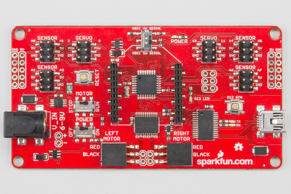
RedBot Mainboard
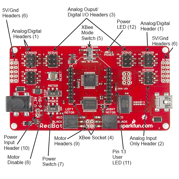
![The RedBot mainboard, labeled for convenient reference]()
The RedBot Mainboard was designed to be as versatile as possible. It has banks of 3-pin I/O break-outs for easily connecting up LEDs, Sensors, or motors. It also has an integrated H-Bridge Driver chip. We have developed an integrated library for the RedBot, if you want to drive the motors manually. Here are the pin outs for the Motor Driver:
LEFT MOTOR:
- Control 1 - Pin 2
- Control 2 - Pin 4
- Motor PWM (Speed) - Pin 5
RIGHT MOTOR:
- Control 1 - Pin 7
- Control 2 - Pin 8
- Motor PWM (Speed) - Pin 6
Here’s a quick tour of the hardware that’s on the board:
Analog/digital headers - These three headers provide one I/O pin, which can be used for analog input as well as digital input or output, as well as 5V power and ground. In addition, the header with A4 and A5 can be used for connecting I2C devices; the RedBot Accelerometer is designed to solder directly to this header, making connecting an accelerometer a snap.
Analog input header - This header provides an additional two analog input pins. These pins can’t be used for digital signals, however.
Analog output/digital header - These two headers provide four pins which can be used for either PWM output or regular digital I/O. Note that the power supply for these headers is connected directly to the battery, providing extra umph for servo motors, but devices expecting 5V should not be connected directly to them!
Wireless Socket - The RedBot has a socket for an XBee module, providing easy wireless interfacing.
XBee Mode Switch A switch allows you to select whether the XBee communicates via the standard serial I/O pins (0 and 1, accessible through the built in Serial command set) or via pins 14 and 15 (A0 and A1), using the SoftwareSerial library. Using the software mode will consume two of your analog inputs, however.
5V / GND Headers - Headers are available to allow the user to tap off the 5V and ground signals.
Power Switch - A power switch puts the board into a very low power consumption mode (microamps or less) allowing you to turn the board off without pulling the power connection.
Motor Disable Switch - A motor disable switch allows you to turn off the motor driver so you can program the board without having it drive all over.
Motor Headers - Headers are available to easily connect up the right and left side motors. The motor control is powered by the TB6612FNG Motor Driver.
Power Input Header - A header has also been provided to allow you to access the input supply, either for purposes of driving additional circuitry or to allow more flexibility than the standard barrel jack does for power sources.
DEBUG LED (pin 13) - An LED is connected to pin 13 to allow basic sanity checks that code is loading and running on the board.
Power LED - A power LED will remain lit whenever the power switch is active.
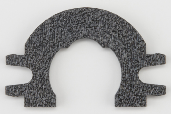
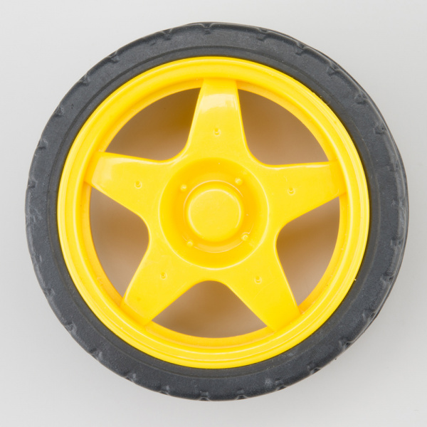
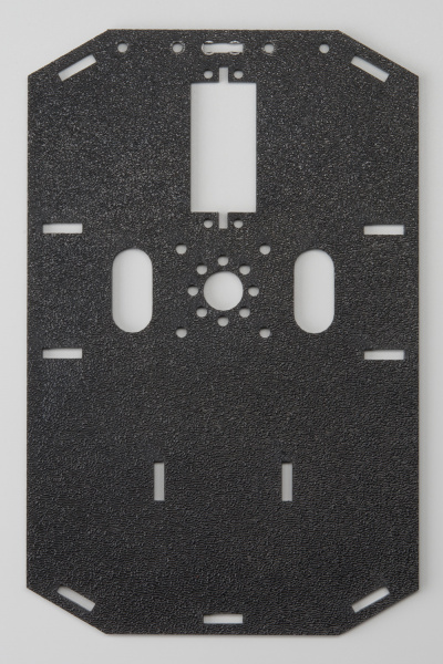
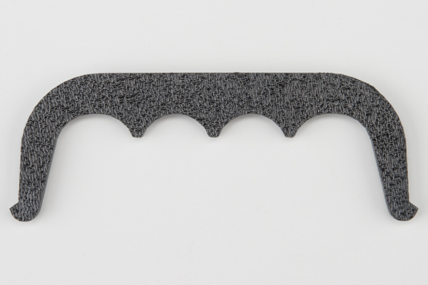
Shadow Chassis
![RedBot Chassis Complete Build]()
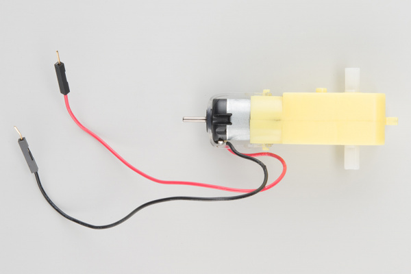
The Shadow Chassis is an economical robot platform with a lot of versatility. It features two gearmotors with 65mm wheels and a caster. The chassis pieces are made of ABS plastic with a wide variety of mounting holes for sensors, controllers, power, etc. Instructions for assembling the chassis can be found here.
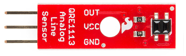
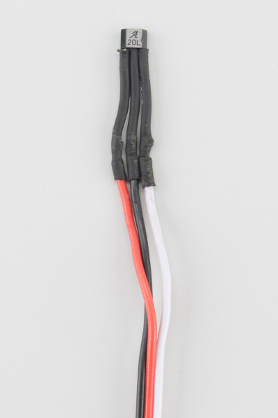
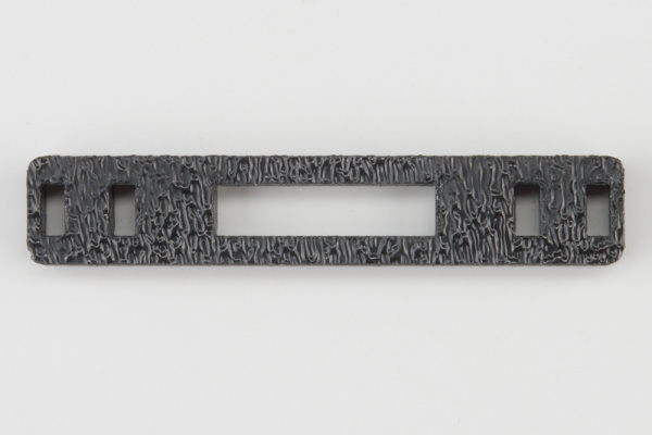
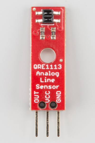
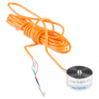
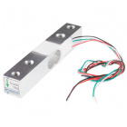
RedBot Line Follower Sensor
![Line sensor]()
The Line Follower sensor is an add-on for your RedBot that gives your robot the ability to detect lines or nearby objects. The sensor works by detecting reflected light coming from its own infrared LED. By measuring the amount of reflected infrared light, it can detect transitions from light to dark (lines) or even objects directly in front of it.
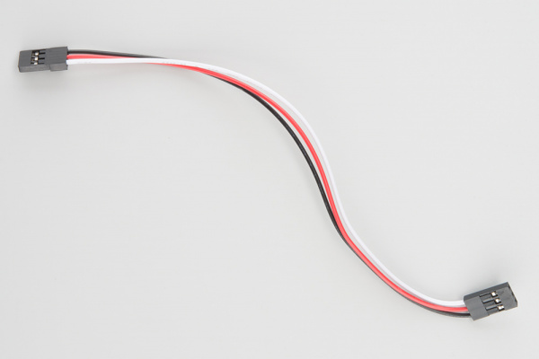
The sensor has a 3-pin header which connects directly to the RedBot Mainboard via female to female jumper wires. Use the included RedBot library to detect lines or objects. A mounting slot lets you easily connect one or more of these to the front or back of your robot chassis.
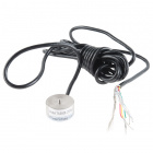
RedBot Accelerometer
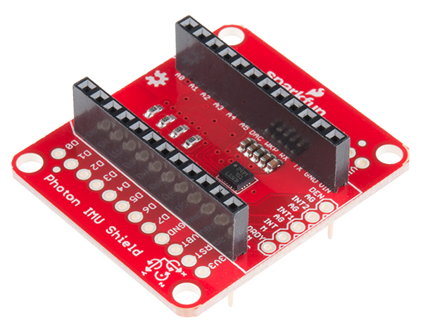
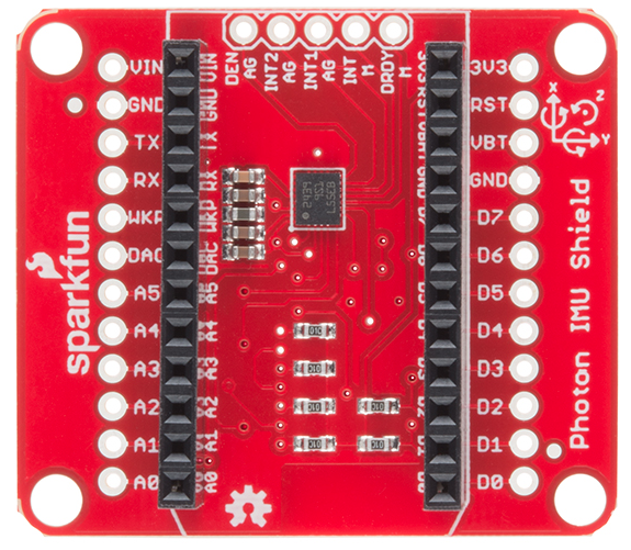
![Accelerometer]()
The Accelerometer sensor is an add-on for your RedBot that provides bump and motion detection. The sensor works by measuring acceleration forces on the x, y, and z axis. By measuring the amount of acceleration (or lack there of) your robot can get a better understanding of its movements.
The sensor has a 2x3 unpopulated footprint which connects directly to the RedBot Mainboard via a female header. You can also solder the sensor directly to the headers on the Mainboard if you wish.
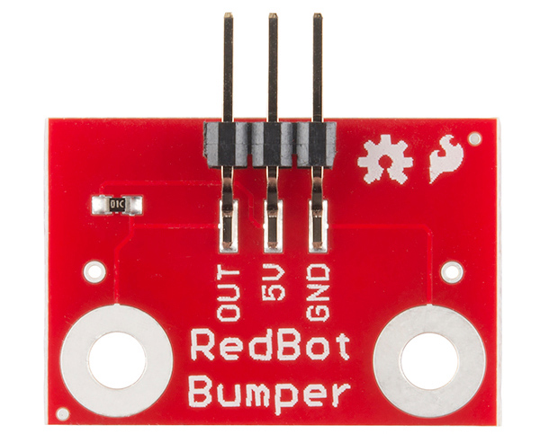
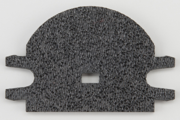
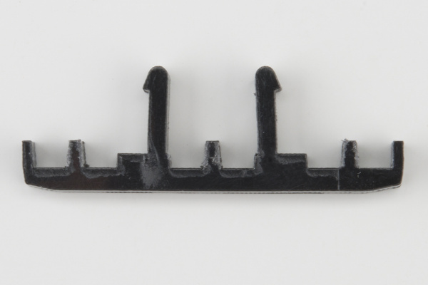
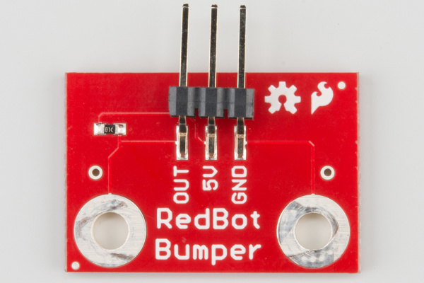
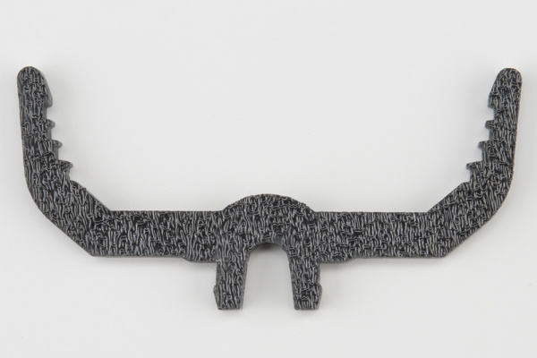
RedBot Whisker Bumper
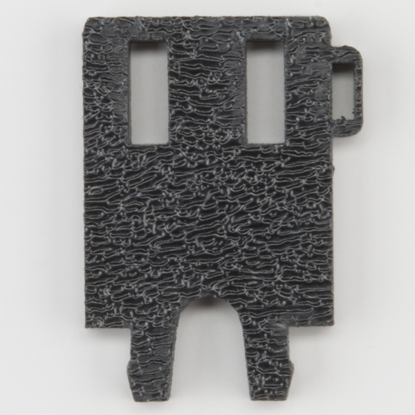
![Bumper board]()
The Whisker Bumper is a very simple sensor comprised of a piece of music wire that closes a contact when bent and a circuit board to interface it to the RedBot. We ship the music wire straight, so you’ll have to bend it to suit your application.
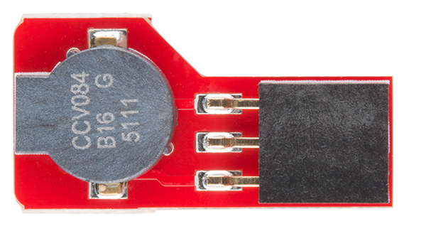
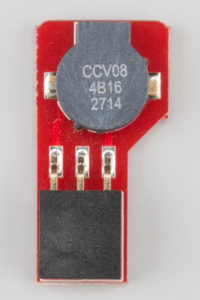
RedBot Buzzer Board
![Buzzer]()
What’s the fun of a robot that doesn’t make beep-beep noises? We’ve made the RedBot Buzzer board to fit nicely on any header on the board, so you can integrate noise with your robot either just for fun or as a nice remote feedback function.
There’s no special library support needed; just use the tone() family of commands already built into Arduino. One note: you can’t use the Buzzer board on pins A6 and A7, as they are analog input-only pins.
RedBot Library Quick Reference
We have written our own library to simplify the programming and interface to the RedBot motors, encoders, sensors, and other peripherals. Here is a quick summary / overview of the RedBot Library, classes, methods, and variables.
RedBotMotors class
RedBotMotors motors;– this creates an instance of the RedBotMotors class. This can only be instantiated once in your code. This allows you to control the motors with simple methods such as:
.drive(motorPower)– this method drives the right side CW and the left side CCW for positive values of motorPower (i.e. drives the RedBot forward), and it does the reverse for negative values of motorPower..pivot(motorPower)– this method spins the entire RedBot CW for positive values of motorPower and CCW for negative values of motorPower..coast()– stops the motors and allows the RedBot to coast to a stop..brake()– applies the brakes using the H-Bridge by shorting out both of the motors. Forces the motors to come to an abrupt stop..leftMotor(motorPower)– controls the leftMotor independantly. Positive values of motorPower spin the motor CW, and negative values spin the motor CCW..leftBrake(motorPower)– applies the brakes the leftMotor..leftCoast(motorPower)– stops the leftMotor allowing it to coast to a stop..rightMotor(motorPower)– controls the rightMotor independantly. Positive values of motorPower spin the motor CW, and negative values spin the motor CCW..rightBrake(motorPower)– applies the brakes the rightMotor..rightCoast(motorPower)– stops the rightMotor allowing it to coast to a stop.
Advanced
If you wish to control the motors independently, the following are the control pins for the left and right motors:
leftMotor_controlPin1 = 2
leftMotor_controlPin2 = 4
leftMotor_motorPwrPin = 5

rightMotor_controlPin1 = 7
rightMotor_controlPin2 = 8
rightMotor_motorPwrPin = 6
The RedBot uses the Toshiba TB6612FNG H-Bridge Motor Driver. The full datasheet is available here.
RedBotEncoder class
RedBotEncoder encoder(leftEncoder, rightEncoder);– this creates a RedBotEncoder object with the left encoder connected to pin leftEncoder and the right encoder connected to pin rightEncoder. This can only be instantiated once in your code.
.clearEnc(LEFT\RIGHT\BOTH)– clears the counter variable for either the LEFT, RIGHT, or BOTH encoders. The labels LEFT, RIGHT, and BOTH are specific types defined in this class.
.getTicks(LEFT\RIGHT)– returns a long integer value representing the number of encoder ticks (counts) for either the LEFT or the RIGHT encoder.
RedBotButton class
RedBotButton button();– Creates an instance of the RedBotButton class on the RedBot. Because the button is hardwired on the RedBot board to pin 12, this initialization is handled inside the library code. This can only be instantiated once in your code.
.read()– returns a boolean value representing the status of the button.
RedBotSensor class
RedBotSensor sensorA(pinNum);– this creates a RedBotSensor object connected to the port (pin) on the RedBot Mainboard. This is primarily used for the line-following sensors, but can be used with any analog sensor. This class can only be instantiated for as many sensors as you have on your RedBot.
.read()– returns an integer value scales from 0 to 255 for the analog voltage read by the sensor. 0 represents 0V and 255 represents 5V.
.setBGLevel()– reads the value of the sensor in it’s ‘nominal’ position. This value is stored as the ‘background’ level.
.setDetectLevel()– reads the value of the sensor in it’s ‘detect’ position. This value is stored as the threshold for a ‘detect’ level.
.check()– returns a boolean value that TRUE if the measured sensor value is greater than ¼ of the difference between the background and the detect levels. Note: This method only works if you have set both the BGLevel and the DetectLevel.
RedBotBumper class
RedBotBumper bumperA(pinNum);– Creates an instance of RedBotBumper object connected to the port (pin) on the RedBot Mainboard. While the RedBotBumper is designed for use with the whisker / bumper switches on the RedBot, it can be used with any digital sensor or switch. This class can only be instantiated for as many digital sensors (bumpers) as you have on your RedBot.
.read()– returns a boolean value for the state of the bumper. It returns TRUE when the bumper switch is closed or connected to GND.
RedBotAccel class
RedBotAccel accel();– Creates an instance of the RedBotAccel object. The RedBot accelerometer uses I2C for communication. Because of this, it needs to be connected to A4/A5 on the RedBot Mainboard. This can only be instantiated once in your code.
.read()– this reads the current values of the accelerometer and stores it into local variables in the library. It does not return any values.
.x– is the raw X-axis accelerometer value read using the .read() method. In general, these values vary from -16000 to +16000. The X-axis is aligned with the FWD/REV direction of the RedBot.
.y– is the raw Y-axis accelerometer value read using the .read() method. In general, these values vary from -16000 to +16000. The Y-axis is aligned with the lateral or RIGHT/LEFT direction of the RedBot.
.z– is the raw Z-axis accelerometer value read using the .read() method. In general, these values vary from -16000 to +16000. The Y-axis is aligned with the UP/DOWN direction of the RedBot.
.angleXZ– is a floating point value for the calculated angle between the X and Z axes of the accelerometer. It calculates the arc tangent between the raw X and raw Z values. On the RedBot, this is the forward / backward tilt.
.angleYZ– is a floating point value for the calculated angle between the Y and Z axes of the accelerometer. It calculates the arc tangent between the raw Y and raw Z values. On the RedBot, this is the side to side tilt.
.angleXY– is a floating point value for the calculated angle between the X and Y axes of the accelerometer. It calculates the arc tangent between the raw X and raw Y values.
RedBotSoftwareSerial class
RedBotSoftwareSerial xBeeRadio();– Creates an instance of the RedBotSoftwareSerial object. This library uses a lot of code from the standard Arduino SoftwareSerial library. The RedBot Mainboard uses pins A0 (14) and A1 (15) for TX and RX when switched to SW_SERIAL.
.begin(baudRate)– opens up the serial communication on the SW_SERIAL TX and RX lines of the RedBot Mainboard at the baudRate. Acceptable baud rates include: 300, 1200, 2400, 4800, 9600, 19200, 28800, 38400, 57600, 115200.
.write()– writes a single bye of data to the software serial port.
.read()– returns a single byte from the software serial port..available()– returns an integer value representing the number of bytes (characters) available for reading from a software serial port.
Experiment 1: Software Install and Basic Test
Install Arduino IDE
In order to get your RedBot up and running, you’ll first need to download the newest version of the Arduino software from www.arduino.cc. This software, known as the Arduino IDE (Integrated Development Environment), will allow you to program the board to do exactly what you want. It’s like a word processor for writing programs. Please visit our Installing Arduino IDE tutorial for step-by-step directions on installing the Arduino IDE.
Connect your RedBot to your computer
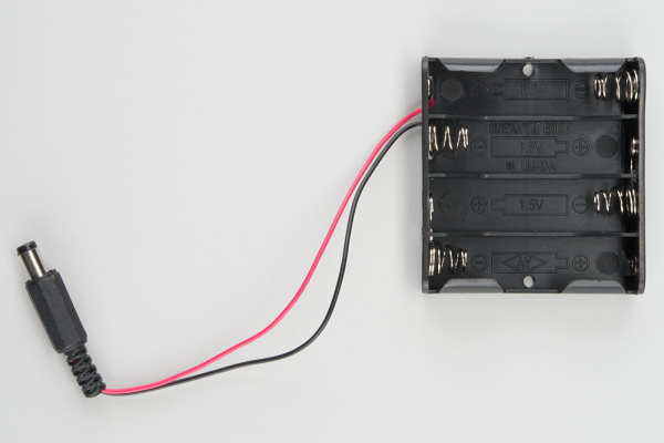
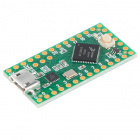
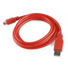
Use a USB miniB cable to connect the RedBot to one of your computer’s USB inputs. Make sure you have the four AA batteries in the battery holder.
![Plug in USB cable]()
Install FTDI drivers
Depending on your computer’s operating system, you will need to follow specific instructions. Please go to How to Install FTDI Drivers for specific instructions on how to install the FTDI drivers onto your RedBot.
Install the RedBot library
A library in Arduino is a set of files containing pre-written code that simplifies instructions and commands to perform certain tasks. We have written a specific library for the RedBot. Make sure you install the RedBot library. You will need it for all the example code. Click the button below to download it.
RedBot Library
Unzip the downloaded file. Copy/Move the RedBot folder to the libraries folder into your Arduino Documents folder. If you need a refresher on how to install an Arduino library, please see our library tutorial.
Example Code
Included in the library are a set of examples for the 9 RedBot Experiments. Click on File > Examples > RedBot > RedBot_Experiments, you should see a list of the 9 Examples we have created.
![RedBot exerpiment examples]()
If you need to find the example code separately, click the button below
RedBot Kit Example Experiments
You can also find the RedBot Kit Experiments example code on the RedBot Github page. To download all the code, click the “Download ZIP” button on the right-hand side of the page.
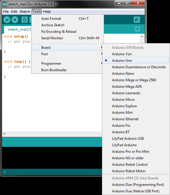
Open the Arduino IDE and select board:
Open the Arduino IDE software on your computer. This step is to set your IDE to identify your RedBot. You will want to select the board, Arduino Uno. To do this, go to Tools > Board > Arduino Uno.
![Select board]()
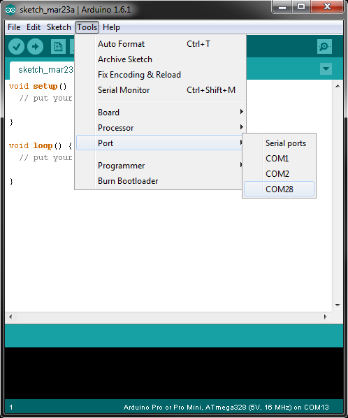
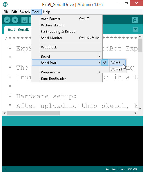
Select your Serial Port
Window users: Select the serial port for the RedBot from the Tools > Port menu. This is likely to be COM3 or higher (COM1 and COM2 are usually reserved for other internal devices). To check, disconnect your RedBot and re-open the menu; the entry that disappears is the one for the RedBot. Reconnect the board, and select that serial port.
![Find serial port in Arduino]()
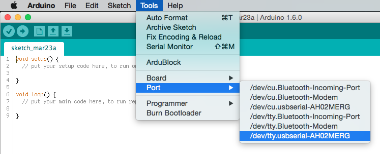
Mac users: Select the serial device of the RedBot from the Tools > Serial Port menu. On the Mac, this should be something with /dev/tty.usbmodem or /dev/tty.usbserial in it. To find out, you can disconnect your RedBot and re-open the menu; the entry that disappears should be the RedBot. Reconnect the board and select that serial port.
![Select serial port in OS X]()
Note: If the Serial Port is not showing up, go back and re-install the FTDI drivers for your machine or try re-starting Arduino.
Experiment 1: Basic Test – Hello World!
Time to make sure the electronics work! The “Hello World” of physical computing is generally a simple blink. On your RedBot Mainboard, there is a debug LED on pin 13. It’s labeled on the board D13 LED.
We are going upload a simple program to the board to make sure everything is up and running.
Go to File > Examples > RedBot_Experiments > Exp1_BasicTest or copy and paste the example code below:
What You Should See
Make sure the battery pack is plugged into the Mainboard, and turn the POWER switch to ON.
![Turn the POWER to ON]()
Click Upload in the Arduino IDE. The code will be compiled and converted into machine langage 1’s and 0’s. You should see two LEDs (TX and RX) blink rapidly back and forth - these indicate data being transmitted and received between the RedBot and your computer. After this is complete, you should see the D13 LED on the RedBot Mainboard LED on and off.
![D13 LED flashing]()
Learn More: LEDs
LEDs – short for light-emitting diodes – are the heart of every good, blinky electronics project. They are perfect for power indicators, debugging, or just adding a little zazz to your project.
LEDs have all sorts of light-related uses. You’re no-doubt used to seeing them in public displays (clocks, traffic lights, and signs) or as energy-efficient light-sources (flashlights, grocery store lighting, and accents), but they also have less obvious uses like infrared remote controls and computer mice.
In fact, recently the Nobel Prize in Physics was recently awarded to Isamu Akasaki, Hiroshi Amano and Shuji Nakamura for the invention of the Blue LED, which allows us to create white light with LEDs!
Code To Note
The RedBot has an LED connected to pin 13. Control of pin 13 can be accessed through the digitalWrite([pin], [HIGH\LOW]) command.
digitalWrite(13, HIGH) puts 5V on pin 13. In this case, this turns the LED on.
digitalWrite(13, LOW) puts 0V on pin 13, and turns the LED off.
The Arduino microcontroller runs at 16 MHz. This means it performs 16 Million operations per second. The digitalWrite() command takes less than 4 uS to execute. In order for us to see the LED turn on, we need to pause or delay the program flow. We do this with the command delay([time_ms]).
In our example, delay(500); 500 indicates the number of milliseconds the program is delayed for.
Going Further
Experiment around with the delay() function to change the rate of the blink. What is the fastest blink that you can still see? 10 ms? 20 ms?
Can you change the blink pattern to resemble a heart-beat? (Hint: You might need to add a second blink sequence to your loop.)
Troubleshooting
My code won’t upload!
- Make sure your USB cable is plugged into both the robot and the computer you’re using to write code.
- Make sure the “POWER” switch is switched to “ON.”
- Double check that you have the right serial port selected under the “Tools” menu. The easiest way to check is to see which item disappears from the menu when you unplug the USB cable, and select that one when you plug the board back in.
- If you have an Xbee module plugged in, make sure the Serial Select switch at the top edge of the board is switched to “XBEE SW SERIAL.”
- Check that you have the right board selected under the “Tools” menu. The RedBot is Arduino Uno-compatible, so select “Arduino Uno” from the list.
My motors aren’t turning!
- This sketch does not turn on the motors; it just blinks. So, the motors should not be spinning.
Experiment 2: Drive Forward
Let’s get your RedBot moving! Let’s start by writing a few lines of code to make your robot drive forward and stop.
To help us out, we are going to utilize parts of the RedBot library. To do this, we need to add a line at the top of our code #include <RedBot.h>. (Remember, Arduino code is case sensitive. This must be typed in exactly the way it’s shown here – otherwise it won’t work.) This “#include” statement will allow us to create a RedBotMotors object that has methods (functions or behaviors) for driving and controlling the RedBot.
RedBotMotors motors;
This line creates an object called motors that allows us to control the right and left motors and drive the robot. See more details below in the Code to Note section.
Before uploading this example code, make sure that the RedBot is in a safe position. The program will start immediately after uploading, and it might drive off your desk, knock over your drink, or stomp through your lunch. We suggest standing the RedBot upright on the flat edge of the rear end so that the wheels are off the table.
Note: When uploading, the power must be on, the motors must be connected, and the board must be powered by a battery. Also, the motor switch should be set to RUN.
Upload this code onto the RedBot.
Go to File > Examples > RedBot_Experiments > Exp2_DriveForward or copy and paste the example code below:
What You Should See
Flip the switch labeled “MOTOR” to “RUN”.
![Flipping switch to RUN]()
Upload the code, and you should see both motors on at full speed for two seconds, and stop. The right motor should spin clockwise (CW) and the left motor should spin counter clockwise (CCW).
Unplug the USB cable from your RedBot and set the RedBot on the floor. Hit the reset button to manually restart your program and watch your RedBot go!
How far did your RedBot move? How long does it drive for? (Can you verify this with a stopwatch?) Be sure to run a few trials. What is the average speed of your robot?
Learn More: Motors
Curious on how motors work? Visit our Motors and Selecting the Right One to learn more about different types of motors and how they work!
Code To Note
Adding the #include <RedBot.h> to the top of your code gives us access to a number of classes, functions, objects, and methods that make controlling the RedBot much easier. The RedBot library has custom routines for creating objects such as:
- RedBotMotors– motor drive class
- RedBotAccel– accelerometer sensors
- RedBotBumper– whisker switch bumpers
- RedBotEncoder– wheel encoder control
- RedBotSensor– general purpose sensors
- RedBotSoftwareSerial– SoftwareSerial for Xbee control
Our focus here is going to be only on the RedBotMotors class. The RedBotMotors class has a number of methods for controlling the motors. In programming, methods are behaviors or questions you ask of an object.
language:c
RedBotMotors motors; // Instantiate the motor control object.
Recall that this line declares an object called motors using the RedBotMotors class. This is sometimes called “instantiating” an object. Now, we can use any of the methods that are a part of this class. To use (or “call”) a method, the command will start with motors. followed by the name of the method. Let’s look at a few examples:
Driving Forward / Reverse
motors.drive([motorPower]) turns both motors. This method takes one input parameter, [motorPower]. [motorPower] can be any integer value from -255 to +255. Values > 0 will cause the robot to drive forward – spinning the right motor clockwise (CW) and the left motor counter-clockwise (CCW) – driving the robot forward. Values < 0 will do the opposite causing the robot to drive in reverse.
language:c
motors.drive(255);  // drives forward at full power.  motors.drive(-255); // drives reverse at full power.
Sometimes running the motors at full power causes the wheels to spin-out. If you notice traction issues, you may want to try playing around with slower speeds.
Stopping
motors.stop() turns off power to both motors and coasts to a stop.
language:c
motors.stop();   // sets the motor speeds to 0 and coasts to a stop.
Sometimes, you might want a more precise stop. the RedBotMotors class also has a brake() method that forces the motors to come to a more abrupt stop.
Try replacing the motors.stop() with motors.brake() in your example code. Measure the distance your robot travels. How much farther does it travel when it “coasts” compared to “braking”?
language:c
motors.brake();       // Stops both motors and applies "brakes" by shorting out the motors
When might you use stop() and when might you want to use brake()?
Going Further
Now that you have control of driving the robot, see if you can get your robot to drive forward for 1 second, stop, and reverse for 1 second. Repeat your test a few times. Does your robot always return to where it started?
How far from your starting point does it return to? What factors might cause it not to come back to it’s starting point?
How might this be useful for robotics applications?
Experiment / Activity
- Adjust the [motorPower] for your robot so that it drives about 2 - 3 feet in 2 seconds. Approximate this. Write down the motorPower here: ______
We’ll use this motorPower later.
- Run a minimum of 5 trials with your robot and measure how far your robot travels in 2 seconds.
- Calculate the average speed of your robot (in inches per second) using the equation:
avgSpeed = distance / time.
Writing your own custom sub-routine \ function - driveDistance()
We’ve already seen two functions used in every Arduino sketch – setup() and loop(). Arduino contains a wealth of built-in functions that are useful for all kinds of things. Visit the Arduino site for a list. In addition to these, you can also easily create your own functions. First, we need to declare & define the function.
When you write your own functions, you make your code neat and easy to re-use. Visit the Arduino FunctionDeclaration page for more information about functions. Every function declaration has the following format:
![Arduino function]()
The return type is void if the function does not return a value or any information. In this case, driveDistance() will simply execute some commands. The functionName will be used in your code to call or reference your function, and the parameters are values or information that you will pass into the function.
In this example, this function will use the the average speed you calculated above to make motion planning easier. It computes the delay used for the driveTime based on a given distance by re-arranging the equation above to: time = distance / avgSpeed
Copy and paste this block of code to the end of your program – after the void loop(){}
language:c
void driveDistance(int distance)
{
// this function takes a distance input parameter and the avgSpeed of your
// RedBot to compute a delayTime for driving forward.
    int avgSpeed = 16;  // average speed in inches per second.

    long driveTime;
    driveTime = (long) 1000 * distance / avgSpeed;
    motors.drive(200);  // make sure you're using the same motorPower as your tests.
    delay(driveTime);
    motors.brake();
}
Now, replace your own drive code with a function call driveDistance(12); Upload and test. Your RedBot should have driven 12 inches. How far did it go? If it drove too far, then adjust the variable avgSpeed until your RedBot is within ½ an inch of 12 inches. Change the driveDistance(12); to driveDistance(24); and test this again. How far did your RedBot go?
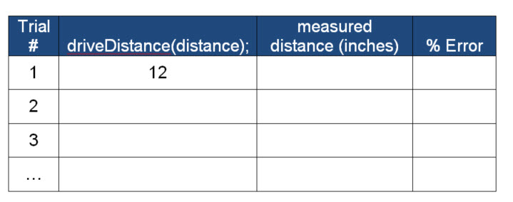
Sample Data Table
Create a data table like this to track your results.
motorPower = ______
avgSpeed = ______
![RedBot speed trials]()
Troubleshooting
Compile Error – ‘RedBotMotors’ does not name a type
language:c
Exp2_DriveForward:18: error: 'RedBotMotors' does not name a type
Exp2_DriveForward.ino: In function 'void setup()':
Exp2_DriveForward:23: error: 'motors' was not declared in this scope
This indicates that the RedBot library is not properly included into your sketch. This is usually a result of one of two things:
- #include <RedBot.h>– this line must be at the top of your code, and RedBot.h must be spelled and capitalized exactly as it is shown here.
- The RedBot library is not in the Arduino libraries folder. Go back to Experiment 1 and make sure that you have properly installed the RedBot library.
My motors aren’t turning!
- Check the “MOTOR” switch on the board and make sure that it’s switched over to RUN.
- Do you have external power connected? The RedBot’s motors need more power than a USB plug can supply, so they won’t run unless a power supply is connected to the barrel jack on the board.
- Make sure that the motors are correctly connected; it may be that you have connected one wire from each board to each power header, or that the wires are plugged into the wrong locations. Match the wire colors to the labels on the board.
My RedBot moves, but spins in a circle!
If the right side and the left side both spin in the same direction (i.e. CCW or CW), then your RedBot will pivot in place. During assembly, it’s important that the motors be mounted on the chassis properly: with the red wire farthest from the underside of the chassis. If you assembled the robot the other way, you can either dis-assemble and flip the motors or flip the wires in the motor headers.
Flipping the wires is usually the easiest fix. Identify which motor is spinning in the wrong direction, and flip the red wire with the black one.
My RedBot is not driving straight! It drives in a curve!
- This is a pretty common thing for the RedBot, and for all robots with independent drive wheels. There are lots of reasons for it, but it’s something that simply must be dealt with.
- First – check to make sure that there is nothing rubbing on either the wheels or on the magnetic motor encoder. Move the wheels out so that they are not rubbing, but still tightly seated into the motor. Any added friction on one side will cause one side to drive faster than the other (resulting it the RedBot pulling to one side.)
- Second – Driving straight requires equal power on both wheels. This requires equal amounts of traction on both wheels. Running the motors up at full power sometimes causes the wheels to “spin out” and lose traction. Try reducing the motorPower to something lower than 255.
- Third – use an encoder to ensure that both wheels turn the same distance each time. “What’s an encoder?” Shucks – we’ll cover encoders later on in Experiment 8.
Experiment 3: Turning
In this experiment, we will look at how to fine-tune the control of the RedBot by controlling the right motor and the left motor separately. We will introduce a few new methods of the RedBotMotor class that will allow us to control the motors separately.
In this experiment, we will break-down the commands for the RedBot to drive forward, turn 90 degrees, drive forward again, and then stop.
Make sure RedBot is in safe location, or standing on the flat back edge of the chassis. This code requires only the most basic setup: the motors must be connected, and the board must be receiving power from the battery pack.
Let’s load this experiment onto the RedBot. Go to File > Examples > RedBot_Experiments > Exp3_Turning or copy and paste the example code below:
What You Should See
After you upload this example code, you should see the wheels spin for a bit, change directions, and then stop. Unplug the USB cable from your RedBot and set the RedBot on the floor. Hit the reset button to manually restart your program. Watch your RedBot go!
On a nice flat surface, your RedBot should drive forward (in a straight line), turn 90 degrees to the right, and then drive forward again. If your RedBot isn’t turning 90 degrees, there are two things you can adjust.
Try changing the turning time by changing the delay(500); The default example is set for 500 ms.
You can also try changing the motorPower during the pivot. Once you have your RedBot making a nice 90 degree turn.
Remember that turning with this system relies on an equal amount of traction on both wheels. Again, if the wheels are slipping or spinning out, you may need to slow down the speed.
Learn More: Turning
The way we turn with a two-wheel differential system is by spinning the right side at a different speed as the left side. In order to pivot to the right, we spin both the right and the left motors in opposite directions. This results in a nice tight turn.
![Pivot right]()
Notice however, that to drive straight, the right side is usually spinning in the same direction as the left side.
![Drive in a straight line]()
While making the motor change directions may result in a tight turn, it is slow. Another way of turning to the right is by only driving the left motor and keeping the other side stopped. This gives us a turn radius pivoting about the non-driven wheel. While the turn may not be as tight, the momentum of the robot is kept going forward.
![Turn right]()
Code To Note
Clockwise or Counter-Clockwise
In the last example, to drive the RedBot forward, we used a single command motors.drive([speed]); Positive speeds cause the RedBot to go forward by spinning the right side clockwise and the left side counter-clockwise.
To control the individual motors, the RedBotMotors class has two methods that are used in this example.
  motors.rightMotor([motorPower]);  // controls the right motor
  motors.leftMotor([motorPower]);   // controls the left motor
Similar to the .drive([motorPower]) method, [motorPower] values can vary from -255 to +255. Positive values spin the motor in the clockwise direction and Negative values spin the motor in the counterclockwise direction.
The RedBot is pretty nimble, so we want to use a lower motorPowers for pivoting. In our example, we set the motorPower to 100 and the delay time to 0.5 seconds. Play around with this until you’re able to get your robot to turn a nice 90 degree turn consistently.
Too abrupt of a turn? How can I turn more gradually? Play around with varying the power to the right side vs. the left side.
setup() vs. loop()
Up until this point, we have always had our code in the setup() portion of the code. Any code that we place in between the curly braces { and } after the setup() runs just once. This is convenient for testing single instructions or routines. But, what if we want our RedBot to repeat a pattern - like doing a figure-8? or a dance?
Any code that we place in the loop() repeats over and over. We have a simple example of a figure-8 pattern. The two forward slashes \\ in front of this code comments the code out from being run. To see un-comment these lines of code, simply remove the two \\.
The RedBot is instructed to turn right and then turn left. Notice that to soften the turn, the motors never change direction. The left motor continues to rotate counter clockwise and the right motor rotates clockwise. The difference in speeds causes the robot to turn.
//  motors.leftMotor(-200);  // Left motor CCW at 200
//  motors.rightMotor(80);   // Right motor CW at 80
//  delay(2000);
//  motors.leftMotor(-80);    // Left motor CCW at 80
//  motors.rightMotor(200);   // Right motor CW at 200
//  delay(2000);
You may need to adjust the speeds and the delay() times to get a good figure-8 pattern.
Going Further
Box step?
Now that you have fine-tuned a 90 degree turn, repeat this four times to see if you can get your RedBot to trace out a box. If you have whiteboard sheets, you can tape a dry-erase marker to the back of the RedBot to trace out your path.
Dance party
Adjust the figure-8 pattern until your RedBot is tracing out figure-8s on the floor. Now, plan out your own dance routine for your robot. See if you can choreograph it to music!
Experiment / Activity
Writing your own custom sub-routine \ function.
Similar to what we did in the DriveForward activity, we will write a sub-routine called turnAngle(). This function will use the the average turningSpeed you calculated above to make motion planning easier.
Copy and paste this block of code to the end of your program – after the void loop(){}
language:c
void turnAngle(int angle)
{
  int turningSpeed = 180; // degreees / second

  long turningTime;
  turningTime = (long) 1000 * angle / turningSpeed;

  motors.rightMotor(-100); // Turn CCW at motorPower of 100
  motors.leftMotor(-100);  // Turn CCW at motorPower of 100
  delay(turningTime);      // turning Time
  motors.brake();     // brake() motors
}
Now, replace your turning code with a function call turnAngle(90); Upload and test. Your RedBot should still be turning 90 degrees. If it’s turning too far or not far enough, then adjust the variable turningSpeed until your RedBot is turning a good 90 degrees. Use this with the driveDistance() function from before to trace out a triangle, a square, and a pentagon.
Troubleshooting
My wheels don’t turn but I hear a high-pitched noise.
The motors may not have enough torque at such a low speed. Try driving the motors at a higher speed, or reducing the weight on the RedBot.
Everytime I plug the USB cable in, the RedBot acts funny for a few seconds! What’s happening?
The RedBot will try to run its code every time it is reset. When you plug something into a computer the computer has to identify what it is. During this period, the computer resets the RedBot controller board multiple times. No harm will come to your RedBot. If it distracts you, switch the motor switch from RUN to STOP and the motors will be disabled.
Experiment 4: Push to Start & Making Sounds (SIK)
Read on if you have the SIK for RedBot or are using the RedBot Buzzer. If not, skip to the next section.
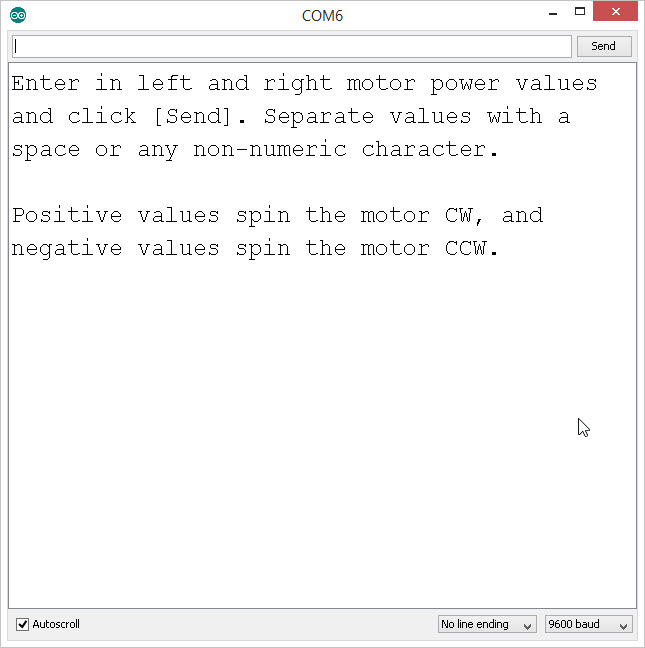
In our past experiments, our RedBot starts running right away after we upload code. Here, we will show an example of how to use the user push button to start our program – and, to make things fun – we’re going to add some noises? After all, what’s a robot without some beep-boop sounds!
Let’s load this experiment onto the RedBot. Go to File > Examples > RedBot_Experiments > Exp4_MakingSounds or copy and paste the example code below:
What You Should See (and Hear)
Your Redbot should make a beep-beep sound and then start spinning the wheels when you press the D12 button next to the USB connector.
![Push D12 on the RedBot Mainboard]()
Code to Note
tone([pin], [freq]) plays a sound of the given frequency on the pin. Since the buzzerPin is set to 9, we can use these commands to play different tones on the buzzer. Rather than just using a blinking LED as an indicator, we can program our RedBot to make sounds at different times to help us know what the robot is doing. This is a way to debug problems just by the sound the robot makes!
language:c
tone(buzzerPin, 1000);  // plays a note of 1 kHz (1000 Hz).
noTone() stops playing a tone on a specific pin.
language:c
noTone(buzzer);  // stops playing the note.
Learn More: Sound
Sound is a longitudinal wave that is caused by vibrations (compressions and expansions) in the air. The Arduino causes sounds by creating a square-wave of a given frequency on the pin. The buzzer reacts to the square-wave by moving the air back and forth creating sound. Because a square-wave is not a pure tone, you will may also hear other harmonics of the base frequency.
A list of notes and their related frequencies can be found here. Can you compose a simple scale? (Hint: The C-Major scale is the easiest, it doesn’t have any sharps or flats.) Human hearing is generally limited between 20 Hz and 20,000 Hz. Can you find where your hearing cuts out? Note: the piezo-buzzer is not capable of producing high fidelity sounds at the low end of the frequency spectrum.
Going Further
Is it hard to remember which frequency corresponds to which note? Download the Music sketch.
RedBot Music Sketch
Unzip it, open it with Arduino, and upload it to your RedBot.
This experiment will play the beginning of “Twinkle Twinkle Little Star” when you press the D12 button. If you look at the code, we use a couple tricks to make things easier.
You will see an extra file in this example called notes.h. This file is a “header” file that is often used to contain extra constants, variables, and sub-routines that are used in your code. notes.h has a list of #define statements that replace noteC4 with 262 (much like a variable, but more efficient).
It also has the length of the notes defined in terms of milliseconds. These are denoted as: WN - whole note, HN - half note, QN - quarter note, EN - eighth note, SN - sixteenth note.
The second trick is a custom function called playNote([note], [duration]). This custom function plays the note using the tone() command and adds a delay(). This simplifies playing notes to just one line of code. For example, to play a middle C for a quarter note, we can type: playNote(noteC4, QN);
What song can you compose? Camptown Races? Amazing Grace? or When the Saints go Marching? Pick a piece to compose as your “theme” song for your RedBot!
Troubleshooting
I don’t hear anything
- If you look at the code, the example program waits for a button press on D12 before doing anything. Press the button and listen.
- Make sure that the buzzer is plugged into the Servo header labeled #9.
Experiment 5: Bumpers (SIK)
Read on if you have the SIK for RedBot or are using the Mechanical Bumpers. If not, skip to the next section.
Now let’s experiment with the whisker bumpers. These super simple switches let you detect a collision before it happens; the whisker will feel a bump just before your robot crashes into it.
One of the most useful elements of the Arduino is its ability to send messages back to a computer over a USB connection. This is accomplished with the “Serial” library, and it allows you to, among other things, report fairly complicated debugging information (reading back variable values, setting multiple different messages to occur under different circumstances, etc).
We’re also going to introduce the concept of “conditional” code - code that only executes when some condition is true. Conditionals are the key to making robots do interesting things; here, we’re going to use the simplest conditional: the if() statement.
Let’s load this experiment onto the RedBot. Go to File > Examples > RedBot_Experiments > Exp5_Bumpers or copy and paste the example code below:
What You Should See
In this experiment, the RedBot should start driving forward until one of the bumpers is hit. When the right side is bumped, the RedBot should reverse and turn the left. When the left side is bumped, the RedBot should reverse and turn right.
Manipulate the timing and the motorPower settings so that your RedBot backs up 12 inches and turns a full 90 degrees after each bump.
Code to Note
Above the setup() and loop(), we declare and initialize two bumper objects using the RedBotBumper class. The initialize statement takes a single parameter indicating which pin the whisker is connected to.
language:c
RedBotBumper lBumper = RedBotBumper(3);  // initializes bumper object on pin 3
RedBotBumper rBumper = RedBotBumper(11); // initializes bumper object on pin 11
The initialize statement automatically sets up the pin with an internal pull-up resistor. This forces the default / nominal state of the input to be HIGH. Not sure what a pull-up resistor is? Check out our Pull-up Resistors tutorial!
lBumper.read() and rBumper.read() returns the state of the bumper. When the RedBot is bumped, the whisker makes contact with a screw bolt that is connected to GND. Therefore, a bump is detected as LOW. We introduce the use of state variables in this example. We read in the state of each bumper and store these in two variables called lBumperState and rBumperState.
language:c
lBumperState = lBumper.read();  // default INPUT state is HIGH, it is LOW when bumped
rBumperState = rBumper.read();  // default INPUT state is HIGH, it is LOW when bumped
Learn More: if() Statements
Want to know how to use logic like a Vulcan? One of the things that makes the RedBot so useful is that it can make complex decisions based on the input it’s getting. For example, you could make a thermostat that turns on a heater if it gets too cold, or a fan if it gets too hot, waters your plants if they get too dry, etc.
Conditional Statements
In order to make these decisions, the Arduino environment provides a set of logic operations that let you make decisions based on conditions or comparisons. Conditional statements should be grouped together using parentheses - e.g. (A == B). These “test” statements or comparisons include:
| Symbol | Name | Description |
| == | IS EQUAL TO? | A == B is true if A and B are the SAME. |
| != | IS NOT EQUAL TO? | (A != B) is true if A and B are NOT THE SAME. |
| > | GREATER THAN | (A > B) is true if A is greater than B. |
| < | LESS THAN | (A< B) is true if A is less than B. |
| >= | GREATER THAN
OR EQUAL TO | (A >= B) is true if A is greater than or equal to B. |
| <= | LESS THAN
OR EQUAL TO | (A <= B) is true if A is less than or equal to B. |
Compound Conditional Statements
Often you might want to string together multiple conditional statements together. The Arduino environment allows us to “chain together” or combine multiple conditional statements with a few symbols. You can combine these symbols to build complex if() statements.
| Symbol | Name | Description |
| && | AND | (condition X) && (condition Y) is true only if BOTH (condition X) and (condition Y) are true. |
| || | OR | (condition X) || (condition Y) is true if condition X is TRUE or condition Y is TRUE or BOTH are TRUE. These are sometimes called "pipes." |
| ! | NOT or INVERSE | !(condition X) is true if (condition X) is false. !(condition X) is false if (condition X) is true. |
For example:
language:c
if ((mode == 1) && ((temperature < threshold) || (override == true)))
{
    digitalWrite(heaterPin, HIGH);
}
…will turn on a heater if the mode varaible is equal to 1 (heating mode) “AND” the temperature is below the threshold, OR if the override variable is set to true. Notice the order of operations are controlled with the parentheses () in these compound conditional statements. Using these logic operators, you can program your RedBoard to make intelligent decisions and take control of the world around it!
Going Further
The current example has the RedBot backing up and turning if either the right or the left bumpers are hit. What should the RedBot do if both bumpers are pressed at the same time? Change the code so that the RedBot backs up and rotates a full 180 degrees when both left and right bumpers are hit.
Troubleshooting
The whiskers aren't triggering anything!
- Check and be sure that they make good contact with the screws when
the whisker bumps into something.
- Make sure that you've got them plugged into the right pins on the
mainboard, and that the other ends plug onto OUT and GND on the
sensor board.
Experiment 6: Line Following with IR Sensors
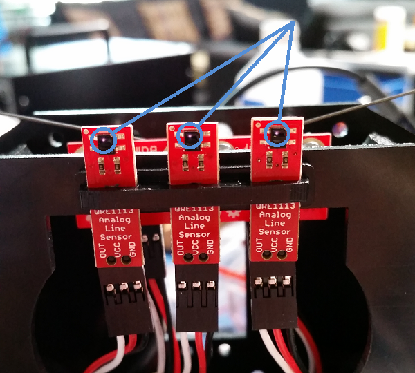
In this experiment, the RedBot will use IR Reflectance sensors to detect characteristics about the surface below the RedBot. The IR Reflectance sensor works by emitting a beam of infrared (IR) light down toward the surface below and measuring the reflected signal. On the IR Reflectance sensor, you will notice two small rectangular shapes. One is the IR transmitter and the other is the detector.
![IR reflectance sensor]()
The IR Reflectance sensors work best when they are close to the surface below the RedBot. The sensor should be about 1/8" above the table. This is an optimal distance for the IR transmitter to illuminate the surface below and measure the reflected light. (Note: Human eyes are non sensitive to IR light, but if you use a CCD camera – like the one in your phone – you can see a small light shining out of the front element)
![IR light in camera]()
Here, you can see a faint pink glow from the IR LED. This is picked up on most digital cameras and cell phones.
Experiment 6.1 – Simple IRSensor Read
This example simply reads and prints the value of the three IR Sensors. Test out different scenarios to characterize the behavior of the IR sensor.
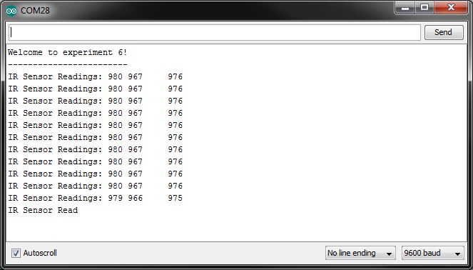
Upload this example code to the RedBot. Go to File > Examples > RedBot_Experiments > Exp6_LineFollowing_IRSensors or copy and paste the example code below. After the code has successfully uploaded, open up the Serial Monitor to view the readings from the sensors.
After uploading this example, leaving the RedBot connected to your computer, set it down on a piece of paper with a dark line (at least ½" wide). You may use a Sharpie Marker, electrical tape, or dark paint. Open up the Serial Monitor (Tools > Serial Monitor) to see the data and sensor readings by the RedBot.
![Readings from IR sensor]()
Sensor Characterization Exercise
The IR Reflectance sensors operate in a pretty short range. They are optimal between 1/8" and 3/16" from the surface. Test this out with your own RedBot.
- Set the robot flat on your desk. What are the nominal values of the three sensors?
- Set the robot down on a piece of white paper. What are the values of the sensors now?
- Making some marks on your paper with different materials: electrical tape, paint, markers, pencils, etc.
- With the robot still sitting on your desk, turn out the lights or throw a blanket over it. What happens to the values of the sensor readings? What do you think is causing this?
- Slowly roll the robot towards the edge of a table. Watch the value as the sensor moves off the edge of the table. What is the sensor value when it rolls off the table?
We can now use these values to program our robot to do things like stay on a table or follow a dark line.
What You Should See
The RedBot won’t do anything on its own with this example. It does, however, report back the sensor readings to the Serial Monitor in Arduino. Click on the Magnifying glass in the upper-right corner to open the Serial Monitor, and watch the values of the line followers change in different situations.
Learn More: Infrared
The IR Reflectance sensor is essentially an IR LED and an IR detector. It works by transmitting a beam of IR light downward toward the surface. If the detector is over a white surface, the reflected light is received by the detector and outputs a LOW signal. When the sensor is over a black surface where the light is absorbed or not reflected, the IR detector outputs a HIGH signal. The IR Sensor module provides an analog value from 0 - 1023 inversely dependent to the amount of reflected IR light.
The analog values read into the Arduino environment vary from 0 to 1023 because Arduino uses a 10-bit Analog-to-Digital Converter (ADC). A value of 0 corresponds to 0 Volts, and 1023 corresponds to 5V read in by the sensor.
Code to Note
To setup communication between the RedBot and your computer, we need to use the Serial object in Arduino. In the setup(), you will see a command: Serial.begin(9600); This initializes the Serial object and determines the data rate (speed) that data will be transmitted and received between the RedBot and the computer. 9600 refers to a baud rate or the number of bis per second. 9600 is a good moderate data rate for most applications. However, other speeds, including 300, 1200, 2400, 4800, 9600, 14400, 19200, 28800, 38400, 57600, and 115200, are supported in Arduino.
language:c
Serial.begin(9600);
To send data from the RedBot to your computer, we have two commands: Serial.print(""); and Serial.println(""); The first command, Serial.print(""); simply prints the text in “ ” or data (in the form of a number or variable) to the Serial bus – this shows up in the Serial monitor. The second command, Serial.println(""); does the same, but adds a carriage-return/line-feed (CRLF) character, moving the cursor to the next line.
language:c
Serial.print("IR Sensor Readings: ");

Serial.println(); // Sends a CRLF character -- moves cursor to next line.
Printing Special Characters
There are a few special characters that can be printed out. These follow all of the standard conventions used in C and C++. A few handy ones include:
| Code | Description |
| \t | TAB character |
| \" | Double quotation mark |
| \' | Single quotation mark |
| \n | CRLF - moves to next line |
RedBot Library
Library support for the line sensor is included in the main RedBot library. The line following sensors will be attached to pins A3, A6, and A7. We will create three objects for each of the three sensors with the following lines of code:
language:c
RedBotSensor IRSensor1 = RedBotSensor(A3);  // initialize a sensor object on A3
RedBotSensor IRSensor2 = RedBotSensor(A6);  // initialize a sensor object on A6
RedBotSensor IRSensor3 = RedBotSensor(A7);  // initialize a sensor object on A7
The RedBotSensor class has only one method of interest to us. It is xxxxxx.read(); This method returns a value from 0 to 1023 based on the input voltage of the sensor. Remember that the xxxxxx represents the name of the object – In this case, IRSensor1, IRSensor2, or IRSensor3.
language:c
Serial.print(IRSensor1.read()); // prints out the sensor value of IRSensor1 to the Serial Monitor
Going Further
Modify the code to make the RedBot drive around and stop before it crosses a black line.
Use the xxxxxx.read() method to check the values and then write some code that will stop the
robot if the level of one of the sensors changes more than a certain amount.
You will need to use an if() statement. Go back to Experiment 5 – Bumpers to remind yourself how to make comparisons and conditional statements within an if() statement.
Let’s take a look at a few basic scenarios.
The center moves off the line and the left sensor is now on the line. Adjust the power to turn / veer left until the center is back on the line.
The center moves off the line and the right sensor is now on the line. Adjust the power to turn / veer right until the center is back on the line.
The RedBot approaches a left turn, the center AND the left are BOTH on the line. Turn 90 degrees to the left.
The RedBot approaches a right turn, the center AND the right are BOTH on the line. Turn 90 degrees to the right.
Play around with these basic ideas to see if you can program your RedBot to:
A) Follow a straight line.
B) Follow a straight line and turn Left or Right.
C) Follow a maze traced out with electrical tape.
Troubleshooting
Nothing is printing in the serial monitor!
- Check to make sure the baud rate is set properly in the serial monitor. There’s a drop-down menu in the lower right corner, and by default, this sketch wants the baud rate at 9600.
I don’t see any change in my sensor values, no matter what I do!
- Double-check your connections.
- Try swapping out the sensor board with one of the others.
Experiment 6.2 – Line Following Example
![Example of line following]()
Here is a quick example of using the line following sensors to follow a dark line on a white background. The algorithm is fairly straight forward. If the center sensor is on the line, the RedBot drives straight (left & right motors are at the same speed). If the right sensor is on the line, we adjust by turning the RedBot to the right (driving the left a little faster and the right a little slower). Similarly, if the left sensor is on the line, the RedBot adjusts by turning to the left (driving the right a little faster and the left a little slower).
This example really only works when the RedBot is moving slowly, and it doesn’t always handle sharp turns well. What can you do to make this example work better?
Experiment 7: Encoder (SIK)
Read on if you have the SIK for RedBot or are using the Wheel Encoder Kit. If not, skip to the next section.
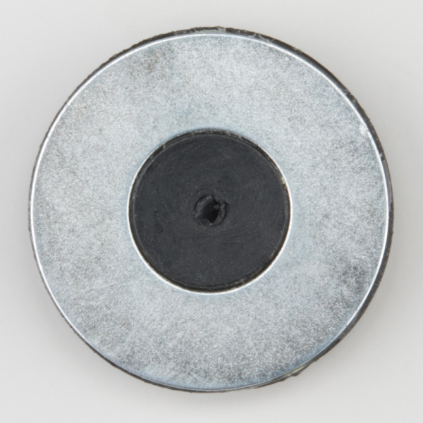
Knowing where your robot is can be very important. The RedBot supports the use of an encoder to track the number of revolutions each wheel has made, so you can tell not only how far each wheel has traveled but how fast the wheels are turning. Included in the SIK for RedBot is a magnetic hall effect sensor and an 8-pole magnetic disk (looks like a washer – but, it’s magnetic!).
This experiment is broken down into three parts: (1) Reading the encoders, (2) Driving a specific distance, and (3) Driving straight.
This first code example is pretty short, but with it we will introduce a how to interface and read the encoder inputs. Go to File > Examples > RedBot_Experiments > Exp7_1_RotaryEncoder or copy and paste the example code below and open up the Serial Monitor.
Experiment 7.1 - Exploring the Encoder
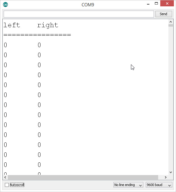
What You Should See
If you open up the Serial Monitor you should see a window like this:
![Arduino Serial Monitor]()
Turn each wheel one complete revolution, and watch what happens. What happens if you reverse directions?
You should see the numbers go up – whether the wheel is turning clock-wise or counter clock-wise. The encoder simply counts the number of times the magnetic poles (N-S) change. The magnet has 8 poles (4 pairs of N-S), so you see 4 counts for every one turn of the magnet. So, why are we seeing more than just 4 counts? Because the motor is connected to a 48:1 gear box, one turn of the wheel is equal to 48 turns of the motor. 48 x (4 magnetic N-S pairs) = 192. Did you see about 192 counts?
Press the reset button to re-start the count at zero. Try it again.
Finally – with the Serial Monitor window still open, push the D12 button on the RedBot. You should see the motors start spinning. You will also see the encoder counts track with the wheels. It should stop after 5 full rotations or at a count of about 960.
Code to Note
RedBotEncoder is another class in the RedBot library. This line initializes the encoder object with the left encoder connected to pin A2 and the right encoder connected to pin 10.
language:c
RedBotEncoder encoder = RedBotEncoder(A2, 10);  // initializes encoder on pins A2 and 10
One of the useful methods in the RedBotEncoder class is encoder.clearEnc([LEFT/RIGHT/BOTH]); This method clears the internal encoder counters for either the LEFT, RIGHT, or BOTH. This is useful for resetting the encoder count just before you start moving.
language:c
encoder.clearEnc(BOTH);  // Reset the counters.
To read the encoder count - also called “ticks” - we use the method encoder.getTicks[LEFT/RIGHT]); This returns a value representing the number of ticks or encoder counts. Because this number can be very large, we use a long variable type for it.
language:c
// store the encoder counts to a variable.
lCount = encoder.getTicks(LEFT);    // read the left motor encoder
rCount = encoder.getTicks(RIGHT);   // read the right motor encoder
Things to try
Looking at the code, we use the motors.brake(); method. Change this to motors.coast(). With motors.coast() the wheels coast and gradually come to a stop. How many more ticks or counts does a coast take compared to a brake()?
Experiment 7.2 - Driving a distance
In this example, we will use the encoder values and the circumference of the wheel to determine how far the RedBot moves.
The standard RedBot chassis has 65 mm (2.56 inch) diameter wheels. The circumference of a circle is equal to π × D, or in this case, approximately 8.04 inches. And using the encoders, one circumference of the wheel (one full rotation) is also equal to 192 ticks of the encoder.
We will use all of this to write a function called driveDistance() that takes two parameters – distance and motorPower to precisely move our robot. We can calculate the exact number of ticks (encoder counts) it will take to move a specific distance.
Go to File > Examples > RedBot_Experiments > Exp7_2_DriveDistance or copy and paste the example code below and open up the Serial Monitor.
What You Should See
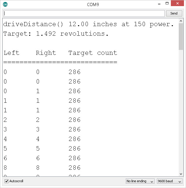
In this example, when you push the D12 button, the RedBot should drive forward 12 inches and stop. If you have the Serial monitor open, you will see this debug information.
![Debug information]()
In the code, given a desired distance, it calculates the number of wheel rotations needed and the target number of encoder ticks (counts). As the wheels spin, it reports back the current count until it reaches its target.
Place the RedBot on a table or flat surface. Push the D12 button. How far did the RedBot move? Repeat this a few times. How far off is your RedBot? Try changing speeds. Is the RedBot more or less accurate when you change the motorPower?
Code to Note
In this example, we created a custom function called driveDistance(); It takes two input parameters – distance and motorPower. If you look at the code, you will see where it calculates the number of revolutions (numRev = distance / wheelCirc;) and where it calculates the target encoder count (targetCount = numRev * countsPerRev;).
language:c
void driveDistance(float distance, int motorPower)
    {
        ...
    }
In this function, we use a while() loop. In this case, the while() loop will repeat over and over so long as rCount is less than targetCount. Inside the loop, we read both the left and the right encoder values, and print these out to the Serial Monitor.
while (rCount < targetCount)
    {
       ...
    }
Did you notice that the right motor doesn’t spin the same speed as the left motor? Sometimes this happens with DC motors. In our next example, we will use the encoders to help us keep the RedBot driving straight.
Things to try
On the line of code that reads driveDistance(12, 150);, try changing the distance to something shorter or longer. Take a tape measure and see how accurate the RedBot is. Try changing the speed. How does the speed affect the accuracy of your driveDistance()?
Finally, you notice that in the while() loop we are only comparing the right encoder count, rCount. We assume that both the left and the right are pretty close – but, try changing the rCount to lCount. How does this affect the behavior of your RedBot? Does it drive farther or shorter? Why?
Experiment 7.3 - Driving a “straight” distance
We have all of this information about how far each of the wheels are moving. We can now drive a precise distance at any speed, but our RedBot still curves a bit to one side or the other. Let’s see if we can use the rCount and lCount information to steer our RedBot straight. Copy and paste the following code into the Arduino window.
/***********************************************************************
 * Exp7_3_DriveStraight -- RedBot Experiment 7.3
 *
 * Knowing where your robot is can be very important. The RedBot supports
 * the use of an encoder to track the number of revolutions each wheels has
 * made, so you can tell not only how far each wheel has traveled but how
 * fast the wheels are turning.
 *
 * This sketch was written by SparkFun Electronics, with lots of help from
 * the Arduino community. This code is completely free for any use.
 *
 * 8 Oct 2013 M. Hord
 * Revised, 31 Oct 2014 B. Huang
 ***********************************************************************/
#include <RedBot.h>
RedBotMotors motors;

RedBotEncoder encoder = RedBotEncoder(A2, 10);
int buttonPin = 12;
int countsPerRev = 192;   // 4 pairs of N-S x 48:1 gearbox = 192 ticks per wheel rev

float wheelDiam = 2.56;  // diam = 65mm / 25.4 mm/in
float wheelCirc = PI*wheelDiam;  // Redbot wheel circumference = pi*D

void setup()
{
  pinMode(buttonPin, INPUT_PULLUP);
  Serial.begin(9600);
}

void loop(void)
{
  // set the power for left & right motors on button press
  if (digitalRead(buttonPin) == LOW)
  {
    driveStraight(12, 150);
  }
}

void driveStraight(float distance, int motorPower)
{
  long lCount = 0;
  long rCount = 0;
  long targetCount;
  float numRev;

  // variables for tracking the left and right encoder counts
  long prevlCount, prevrCount;

  long lDiff, rDiff;  // diff between current encoder count and previous count

  // variables for setting left and right motor power
  int leftPower = motorPower;
  int rightPower = motorPower;

  // variable used to offset motor power on right vs left to keep straight.
  int offset = 5;  // offset amount to compensate Right vs. Left drive

  numRev = distance / wheelCirc;  // calculate the target # of rotations
  targetCount = numRev * countsPerRev;    // calculate the target count

  // debug
  Serial.print("driveStraight() ");
  Serial.print(distance);
  Serial.print(" inches at ");
  Serial.print(motorPower);
  Serial.println(" power.");

  Serial.print("Target: ");
  Serial.print(numRev, 3);
  Serial.println(" revolutions.");
  Serial.println();

  // print out header
  Serial.print("Left\t");   // "Left" and tab
  Serial.print("Right\t");  // "Right" and tab
  Serial.println("Target count");
  Serial.println("============================");

  encoder.clearEnc(BOTH);    // clear the encoder count
  delay(100);  // short delay before starting the motors.

  motors.drive(motorPower);  // start motors

  while (rCount < targetCount)
  {
    // while the right encoder is less than the target count -- debug print
    // the encoder values and wait -- this is a holding loop.
    lCount = encoder.getTicks(LEFT);
    rCount = encoder.getTicks(RIGHT);
    Serial.print(lCount);
    Serial.print("\t");
    Serial.print(rCount);
    Serial.print("\t");
    Serial.println(targetCount);

    motors.leftDrive(leftPower);
    motors.rightDrive(rightPower);

    // calculate the rotation "speed" as a difference in the count from previous cycle.
    lDiff = (lCount - prevlCount);
    rDiff = (rCount - prevrCount);

    // store the current count as the "previous" count for the next cycle.
    prevlCount = lCount;
    prevrCount = rCount;

    // if left is faster than the right, slow down the left / speed up right
    if (lDiff > rDiff)
    {
      leftPower = leftPower - offset;
      rightPower = rightPower + offset;
    }
    // if right is faster than the left, speed up the left / slow down right
    else if (lDiff < rDiff)
    {
      leftPower = leftPower + offset;
      rightPower = rightPower - offset;
    }
    delay(50);  // short delay to give motors a chance to respond.
  }
  // now apply "brakes" to stop the motors.
  motors.brake();
}
Code to Note
In this code, we use the motors.leftDrive() and motors.rightDrive() to independently drive each side. In the while() loop, we calculate a “speed” based on the difference in the current encoder count compared to the last cycle.
If the left difference lDiff is greater than the right difference rDiff, we reduce the leftPower and increase the rightPower. And, if lDiff is less than rDiff, we increaes the leftPower and reduce the rightPower. This is a simple feedback loop that will help keep the RedBot driving straight.
Things to try
Take a look at the last experiment 7.3. There is a function called driveStraight that checks the difference in the lCount and the difference in the rCount from the previous encoder reading. It uses this to add or subtract a power offset to the right or left motors. On the line that reads: int offset = 5; Change the offset to a bigger number. How does this change the behavior of your RedBot.
Going Further
You have learned a lot so far! Encoders are great feedback sensors for robotics. In our earlier examples, when we used delay() and dead reckoning to drive a specific distance, we relied on the batteries maintaining a constant voltage and the motors to behave predictably each time. With encoders, we know exactly how far each wheel rotates.
For a challenge, write your own turn() function that uses the encoders to help the RedBot turn a 90 degree angle. With the encoders, your results should be pretty consistent each time.
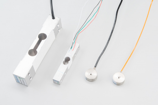
Learn More: RedBot Sensor - Encoder
The wheel encoder on the RedBot is a Hall Effect Sensor that detects changes in magnetic fields. As the round magnetic disk mounted to the back of the drive motors rotates, it moves it’s N/S poles past the sensor. Each transition from N/S is marked as a count. The disk is an 8-pole magnet (4 north-south pairs) and results in 4 ticks or counts for each revolution of the motor.
The motor is mounted inside a 48:1 gearbox. This means that the motor will spin 48 times for one full rotation of the wheel (48 x 4 = 192 counts).
Since the wheel is about 2.5 inches (65mm) in diameter, that corresponds to about eight inches or 200mm traveled per full revolution. So, 192 counts of the encoder is equal to about 8 inches of linear travel.
Now, to forestall angry messages about conversions and precision of measurement (for instance, if you ask Google how many mm are in 2.5 inches, it’ll tell you 63.5, not 65, and the circumference of a 2.5 in diameter is certainly not exactly eight inches), I invite you to consider this your first lesson in precision and tolerance. Given all the tolerances involved in this system, eight inches/200mm per revolution is almost certainly a “good enough” answer, and if you need better than that, you’ll need a more expensive robotics platform.
Troubleshooting
The encoder counts aren’t incrementing!
- Double check the wiring. Make sure that the encoders are plugged into ports A2 and 10 on the RedBot Mainboard.
- Make sure that the magnetic disk is still in place. If it falls off, a little super glue or epoxy will do the trick.
- Make sure that the encoder sensor is bent and next to the magnetic disk.
Experiment 8: Accelerometer
The RedBot Kit comes with an accelerometer board that can be used to detect bumps or to tell whether the robot is on an incline. This example will use the accelerometer as an input to “wind up” the robot.
Experiment 8.1 - Exploring the Accelerometer
Let’s load this experiment onto the RedBot. Go to File > Examples > Exp8_1_AccelerometerRead or copy and paste the example code below.
What You Should See
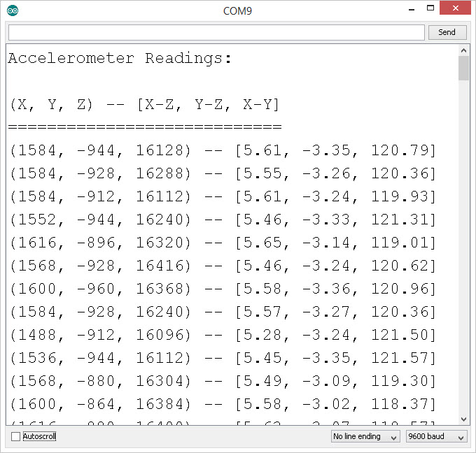
This simple sketch introduces us to the RedBotAccelerometer class object. The RedBotAccelerometer class has a .read() method that reads the current X, Y, and Z accelerometer readings and calculates the X-Z, Y-Z, and X-Z angles. Upload this sketch to your RedBot, open up the Serial Monitor, and rotate/tilt the RedBot around to see how the values change.
![Reading the accelerometer]()
What is the maximum values that you see for any one axis?
Code to Note
RedBotAccel is another class in the RedBot library. This line initializes the accelerometer object. The Accelerometer sensor uses a protocol called I2C. For this, the sensor must be connected to pins A4 & A5 on the RedBot Mainboard. This is why the accelerometer must be plugged into the front-right corner of the RedBot.
language:c
RedBotAccel accelerometer;
The RedBotAccel class has one method (function) that we need to use. It is the .read() method. This sends the commands to the sensor to read the X, Y, and Z axis accelerations and calculate the X-Z, Y-Z, and X-Y angles. The accelerometer works by measuring the vector force of gravity on a small mass in the X, Y, and Z directions. By using the component values of each vector, you can determine the orientation of the RedBot with respect to Earth’s gravitational pull.
language:c
accelerometer.read(); // updates the x, y, and z axis readings on the accelerometer
After we have called the .read() method, the accelerometer values are stored in public variables that are part of the class. These variables are: x, y, z, angleXZ, angleYZ, and angleXY. The variables x, y, and z return an integer that represents the raw accelerometer values. The variables angleXZ, angleYZ, and angleXY return a floating point number representing the angle in each of these planes:
language:c
int xAccel = accelerometer.x;
int yAccel = accelerometer.y;
int zAccel = accelerometer.z;

float XZ = accelerometer.angleXZ;
float YZ = accelerometer.angleYZ;
float XY = accelerometer.angleXY;
The raw x, y, and z readings indicate acceleration along each of these axes. You can see the markings on the sensor indicating the direction. X points in the forward direction, Y points to the left, and Z is straight up. The absolute reading should vary between something close to 16,000 to -16,000, and when the robot is neutral or flat, the reading will be near zero (+/- perhaps 500 counts, depending on how level it is).
Things to Try
Can you figure out what mathematical function is used to calculate the angle in each plane – XZ, YZ, and XY? (Hint: Think back to you triangles and trig identities).
Experiment 8.2 - Wind-up
This is a fun demo that uses the accelerometer reading to detect the tilt / incline of the Redbot. As you tilt the RedBot, the wheels should start to spin. This mimics a “wind-up” toy action. Set it down on the floor and watch it drive slowly to a stop.
Go to File > Examples > RedBot_Experiments > Exp8_2_WindUp or copy and paste the example code below:
What You Should See
If your Redbot is sitting up-right, you should see the Redbot motors start spinning. As you change the incline or tilt of the position of the Redbot, it will change speed. Set the robot on the floor, and it should slow to a stop.
Code to Note
In robotics and electronics, we often have the need to scale our inputs to a different range of values. In Arduino, there is a nifty function called map() that does this for us. map() uses 5 parameters or inputs. map(value, fromLOW, fromHIGH, toLOW, toHIGH). Basically, it scales a value that is in a range of between fromLOW to fromHIGH to a new range that is toLOW to toHIGH. In this example, we are scaling the angle from 0 to 90 degrees to an output value of 0 to 255 for the motorPower.
language:c
motorSpeed = map(XZ, 0, 90, 0, 255);
Things to Try
What other things can we do with the accelerometer? How about a tilt sensor that lights up different LEDs to indicate what direction the RedBot is tilted? How about a sound maker that varies the pitch of the sound based on the angle of the RedBot? You have access to the three independent vectors (X, Y, & Z) and the three relative angles in the X-Z, Y-Z, and X-Y planes. Come up with something fun to do based on the accelerometer readings!
Learn More: Accelerometer
The accelerometer sensor is an add-on for your RedBot that provides bump and motion detection. The sensor works by measuring acceleration forces on the x, y, and z axis. By measuring the amount of acceleration (or lack thereof) your robot can get a better understanding of its movements.
To learn more about accelerometers, please check out our Accelerometer Basics tutorial.
Going Further
Use the accelerometer to start a program. Shut down when things have gone wrong (turned over). After doing that, try to combine what you have learned to make the RedBot start driving around a line when the accelerometer is bumped.
Troubleshooting
The accelerometer values in the Serial window aren’t changing!
Experiment 9: Remote Control
At the heart of almost every robotics project is remote control. Up to this point, we have only looked at autonomous or pre-programmed control of the RedBot. Using a few simple commands, we will setup the RedBot to respond to Serial data that is transmitted from your computer.
Let’s load this experiment onto the RedBot. Go to File > Examples > Exp9_SerialDrive or copy and paste the example code below:
What You Should See
After uploading this sketch, open up the Serial Monitor.
![Remote control with the RedBot]()
In the code, we print out a few lines in the setup() using the Serial.println() command. These are used as user-interface prompts. Type in one or two numbers into the input window and click [Send]. The motors should start spinning. The values that you send to the RedBot will drive the left and the right motors, respectively. What happens when you type in a negative value? How would you stop the motors?
Code to Note
language:c
Serial.begin(9600);
This first command in the setup() starts the Serial communication between the RedBot and your computer. The “9600” specifies the baud rate or speed that you can communicate. Did you notice that the RedBot response lagged a little from when you sent it commands to change speeds? Try changing the baud rate to 57600. Note that when you change the baud rate, you need to re-upload your code and change the speed on the Serial Monitor.
![Changing the baud rate]()
If you forget to change the baud rate in the Serial Monitor, all you’ll see is gobbly-gook. Make sure the baud rate in the Serial Monitor matches what you have in your Serial.begin() in your code.
![Wrong baud]()
language:c
if(Serial.available() > 0)
{
}
In the loop() part of the code, we start with a simple if() conditional statement. Serial.available() returns the number of bytes waiting to be read in. Remember that this is on the RedBot. So, when we type in “-150 150” [Send], there are 8 characters worth of data being sent to the RedBot.
language:c
  leftPower = Serial.parseInt();  // read in the next numeric value
  leftPower = constrain(leftPower, -255, 255);  // constrain the data to -255 to +255

  rightPower = Serial.parseInt();   // read in the next numeric value
  rightPower = constrain(rightPower, -255, 255);  // constrain the data to -255 to +255
Next, we use a nifty function of the Serial object called .parseInt(). This function reads in the next numeric value and converts this to a number. Note that when we pass data back and forth on the Serial Monitor, we generally pass data as ASCII characters. Because these are not actually number values, we need to use this function to read in the data and convert them.
You can use this same method to send any number of data items. For this example, we’re just sending two pieces of data (leftMotor power and rightMotor power). You can use this to signal turning on LEDs, making sounds, or moving motors.
Learn More: Serial
The Serial object in Arduino has many other methods, functions, and features. Serial communication is one of the simplest methods to send data, instructions, and commands between the RedBot and your computer. If you look closely at the RedBot, you should see two lights blinking back and forth whenever data is being sent or received.
One LED represents data being received (RX) and the other represents data being transmitted (TX). For the Arduino, all of this communication happens over two wires (one for RX and one for TX). We can send data at speeds up to 115200 baud (that’s 115200 bytes per second!).
In today’s world of GB/s data rates, this may not seem like that much, but this is remarkably fast given that it’s just being sent over two very thin wires.
Going Further
Want to go wireless? Well – you’ll need a few things to get started. First, you’ll need two XBee Series 1 and an XBee Explorer USB.
The XBee radio modules are ready to go with their default settings. The radios are on a generic network address (3332) and are broadcasting out to any and all radios that are on this network. Note: The default settings will not work in a classroom setting or where there may be more than one set of wireless RedBots.
To start, plug one XBee into the XBee Explorer USB. It is very important to make sure that the pins all line up and the XBee matches the white pentagonal outline on the XBee Explorer. Using a USB cable, connect this to your computer. Your computer may “find a new device” and attempt to install drivers. Allow your computer to complete this process before moving on.
Plug the other XBee into your RedBot. Again, make sure that the pins line up and the XBee matches the white pentagonal outline. Also, check to make sure that the switch next to the XBee header is set to XBEE HW SERIAL.
The RedBot should now be connected to your computer wirelessly: through the two XBees. The XBee Explorer will identify as a different Serial Port on your computer. Go to the Tools > Serial Port menu and change this to the Serial Port for the XBee.
![Select Port for XBee]()
Now, open up the Serial Monitor. Push the [Reset] button on the RedBot, and you should see text come across. Type in a couple numbers and see if your RedBot starts moving. With the default XBee configuration, you can only communicate at 9600 baud.
![Controlling the RedBot wirelessly]()
Notice that this uses a different COM Port.
If you want to use a different baud rate, or you want to run multiple RedBots in a single classroom, you will need to re-configure each of the XBee radios. For this, you can use a program like XCTU. XCTU is a configuration tool made by Digi, the manufacturer of the XBee Wireless modules.
For more information on XBees or wireless projects check out our tutorial on learn.sparkfun.com:
Exploring XBees and XCTU
How to set up an XBee using your computer, the X-CTU software, and an XBee Explorer interface board.
Resources and Going Further
Get moving!
Hopefully, this guide has given you enough information to get started with the RedBot!
Once you’ve mastered the art of line following robots, try you hand at other types of robots.
Resources
GitHub repositories:
Beyond the Tutorial
Here are some guides and projects to get you going with other ideas:
Alternative Arduino Interfaces
We admit the Arduino IDE isn't for everyone. Here are some other options for programming your Arduino boards, including web interfaces and graphical programming languages.
learn.sparkfun.com |CC BY-SA 3.0
| SparkFun Electronics | Niwot, Colorado