Photon Weather Shield Hookup Guide a learn.sparkfun.com tutorial
Available online at: http://sfe.io/t94
Introduction
Have you ever wanted to have your own weather station? Or how about your own thermostat capable of controlling your home climate from the Web? Using the Photon module from Particle coupled with the Photon Weather shield from SparkFun, you can now connect your weather related project to the Internet of Things!

Covered in this Tutorial
This tutorial will cover all the hardware features on the board, all the libraries and firmware you need to communicate with the sensors, how to communicate with said sensors, and how to add additional sensors and parts to create a fully-functional, Internet-connected weather station.
Suggested Materials
I you are looking to just measure Temperature, Humidity, and/or Barometric Pressure (Altitude), you can integrate the Photon Weather Shield into your project right out of the box! No soldering necessary!
The Weather Shield also has numerous optional ports on which other sensors or other devices, such as Bluetooth or XBees, can be added. If you wish to follow along with the weather station project at the end of this tutorial, you can find the parts used in the wish list below.
We really wanted to create a customizable shield for numerous weather project applications. You can add or omit any of the sensors you see throughout this tutorial as well as adding parts not mentioned here.
Suggested Reading
The following are suggestions for other resources to read before getting started with your Photon Weather Shield.
If you have never worked with the Photon or the Core before, we highly recommend visiting the getting started documentation available on the Particle site.
If you are interested in collecting and storing weather data, our Getting started with Phant tutorial is a great place to start.
The Photon Weather Shield borrowed heavily from the Arduino Weather Shield design while also taking customer feedback into consideration to create a more versatile product. There’s lots to be learned from the Hookup Guide for that shield as well.
Our WIMP Weather Station tutorial has lots of great information on how to create a truly weather-proof weather station that can withstand the elements (including wind!). This is a must read if you intend to house your project outdoors.
Check out the Hookup Guides for each of the sensors located on the shield for more information specific to that sensor.
If you are unfamiliar with any of the concepts below, we suggest checking out those tutorials as well.
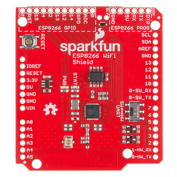
Hardware Overview & Assembly
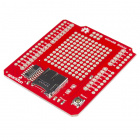
The Photon Weather Shield has a lot of functionality packed into one tiny package. Let’s go over each section of the shield.
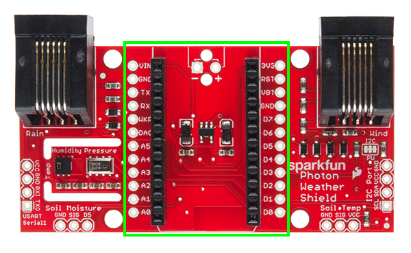
Photon Footprint
Both the Core and the Photon fit right onto the shield. Copper pours underneath the antenna were restricted so as not to interfere with wireless connections. Each pin is also broken out to the sides of the Photon for accessibility. When attaching a Photn, be sure to line up the beveled end of the Photon with the beveled silkscreen on the PCB.
Power
The simplest way to power the shield is to attach a Photon, and then power the Photon through the micro USB connector. This will power the Photon as well as all the components on the shield.

The downside to that power scheme is that micro USB connectors tend to be fragile when put under a lot of mechanical stress, and they can rip right off the PCB if pulled too hard. Thus, we provided a few other options for power connectors. On the underside of the shield, you’ll find a footprint for both an SMD Barrel Jack and a 2-pin, 3.5mm screw terminal. Either of these can be soldered to the PCB and used for alternate power inputs. The maximum voltage supplied on these alternate connectors should not exceed 12V. For a detailed explanation, read on.

Powered through the Barrel Jack.
For the screw terminal, you can solder it to either side of the shield, since it fits underneath the Photon. Be sure to keep track of which pin is (+) and which is (-).

Powered through the Screw Terminal.
On-Board 3.3V Regulator & Power Solder Jumpers
There is also a 3.3V regulator on the shield. If you are powering the Photon through the micro USB connector, this regulator is bypassed. Powering through one of the alternative power connectors mentioned above routes power through the shield’s 3.3V regulator, which is then tied to the 3.3V rail on the Photon, powering it as well.
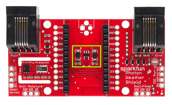
On-board 3.3V regulator and accompanying circuitry.
The main benefit to using the on-board regulator is that is has a higher maximum voltage rating than the regulator located on the Photon. As stated in the Photon datasheet, if power is supplied directly to the VIN pin on the Photon , the voltage should be regulated between 3.6VDC and 5.5VDC. In contrast, the MIC5219 regulator is rated for 2.5VDC to 12VDC, as per its datasheet.
However, if you would rather have the alternative power source route power through the regulator on the Photon (for lower current consumption during sleep perhaps), simply cut the trace on the Power Select jumper (between the VREG and RAW pads), and add a blob of solder between Raw and P_VIN (Photon VIN) pads. Just be sure to not exceed voltages of 5.5-6V once this alteration has been made.


On-Board Sensors
The weather shield comes with two on-board sensors. Together, these two sensors can give you a lot of information about the environmental conditions around you or your project.
HTU21D Humidity & Temperature Sensor
The HTU21D is a low-cost, highly accurate, digital humidity and temperature sensor. This sensor communicates over I2C and comes connected to the Photon’s I2C bus by default, making development a breeze. The PCB around this sensor is milled out and copper pour is restricted in that area to reduce the amount of parasitic heat coming from other components on the shield, including the Photon itself, that may affect your temperature readings.

MPL3115A2 Barometric Pressure
The MPL3115A2 is a MEMS pressure sensor that provides Altitude data to within 30cm. The sensor outputs are digitized by a high resolution 24-bit ADC and transmitted over I2C. Pressure output can be resolved with output in fractions of a Pascal, and Altitude can be resolved in fractions of a meter. The device also provides 12-bit temperature measurements in degrees Celsius. This sensor also communicates over I2C and comes connected to the Photon’s I2C bus by default.

More information on how to use these sensors can be found in the Libraries and IDE section of this tutorial.
RJ-11 Weather Meter Connectors
If you would like to place your Weather Shield outdoors and create a fully-functional weather station, you can grab a set of Weather Meters and connect them to the RJ-11 connectors located on the Weather Shield. With these meters attached, you can measure wind speed, wind direction and rainfall.

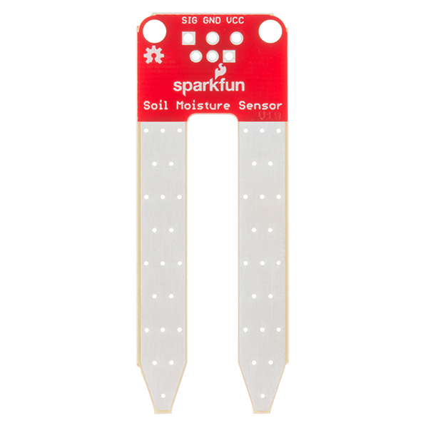
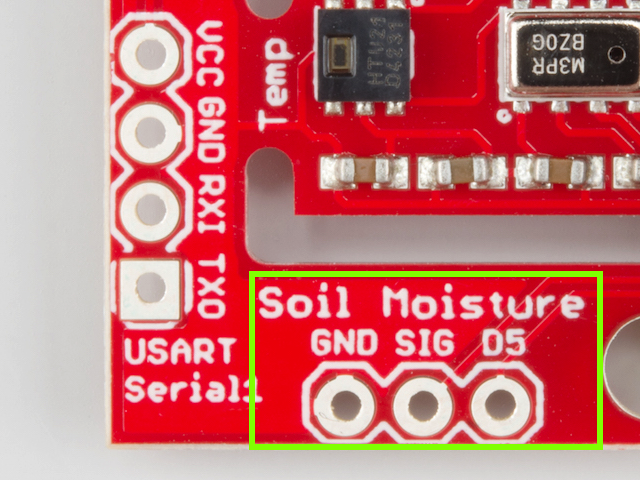
Soil Moisture & Soil/Water Temperature
For those who want to keep track of their houseplant conditions or for those who want to know topsoil conditions in their gardens, the weather shield has an optional port for a soil moisture sensor (Coming Soon!) Leaving the soil moisture sensor powered all the time leads to corrosion of the probes. To account for this, this port breaks out Digital Pin D5 as the power pin for the sensor, allowing the Photon to power the sensor, take a reading, and then disable power, giving the probes a longer lifespan. The moisture level can be read on Analog Pin A1.
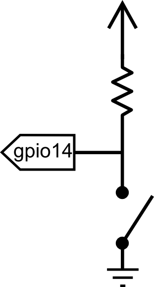
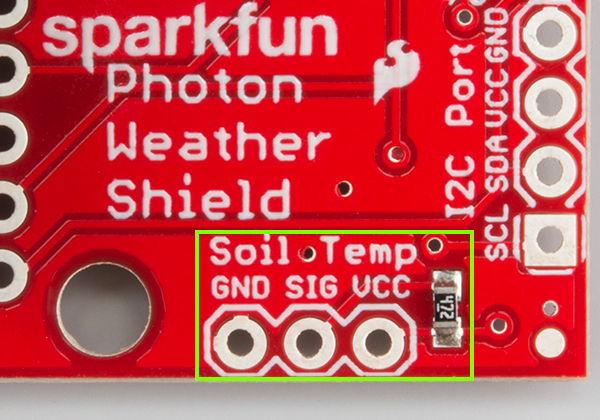
In addition to soil moisture, you can also add a waterproof temperature senor. Whether you have a pond you’d like to monitor near your weather station or you want to know if the ground is still frozen or not, this can be a great addition to any weather station. The waterproof version of the DS18B20 temperature senor is a go-to option for many users looking to sense the temperature of various environments that may not be so kind to electronics. A port for this senors is broken out along with the necessary 4.7K pull-up resistor located between the Vcc and Signal lines. The Signal line is connected to Digital Pin D4. Communicate with this sensor using the OneWire and Dallas Temperature libraries.
Assembly
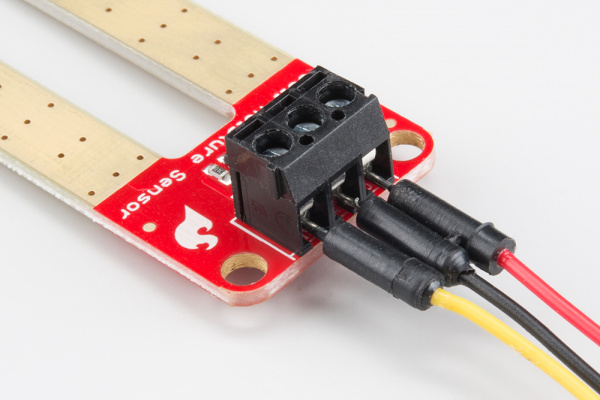
The waterproof temp sensor comes with plenty of cable length and pre-stripped, pre-soldered wires on the end, making assembly straightforward. For the Soil Moisture sensor, you’ll have to get a little more creative. You could always just use some hookup wire. We’ve found that retired cables, such as USB cables, can be sacrificed to make cables for such projects. A black USB cable with the green wire snipped matches the look of the DS18B20 cable quite well.

The snipped USB cable (right) and the DS18B20 cable (left), both secured to standoffs with zip ties.
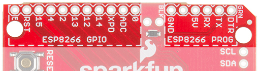
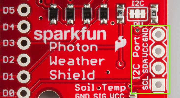
I2C Port
I2C is becoming increasingly popular as a means by which to communicate with sensors. Thus, it made sense to add an I2C port to allow users to add other sensors to their project. One great example would be adding an external light sensor. Since most weather stations need to be enclosed in a weather proof housing, having a light sensor on-board didn’t make much sense. However, adding the I2C port allows one to connect sensors such as the TSL2561 Luminosity Sensor or the ISL29125 RGB Light Sensor along with a whole slew of other I2C sensors.
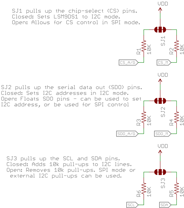
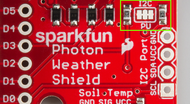
I2C Pull-ups
Many SparkFun I2C Breakouts have solder jumpers for disabling the pull-up resistors necessary on most I2C designs. The Photon Weather Shield is no different. If you already have a sensor that has pull-ups, you can disable them on the shield by cutting the traces with a hobby knife. Or, if you would rather leave the shield as is, you can disable the pull-ups on every I2C you add to the bus. The important thing to remember is that only one device on the bus needs to have its pull-ups active. All others should be disabled.
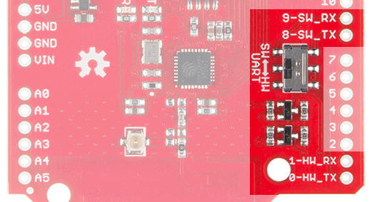
Serial 1 Port
Last but not least, there is another port broken out, this time for the USART Serial 1 port on the Photon. Serial ports are great for debugging. They also allow for various other wireless technologies to be attached for mesh networking or for user feedback via an LCD or other display. Let’s say you wanted additional sensors around you home, well beyond the range of your WiFi signal. You could attach an Xbee Explorer to the Serial 1 port on the Weather shield and have your other node (consisting of a stand-alone XBee or an XBee Arduino combo, for example) out in the field, feeding data back to the Photon, which then sends the collective data to the web.

Another use case is wanting to have your weather station outside while still receiving data on a display indoors somewhere. This could easily be accomplished by attaching a BlueSMiRF Bluetooth module to the Serial 1 port and having another BlueSMiRF attached to a Serial Graphic LCD display installed in your home. We’ll show you how to do exactly that later in this tutorial, amongst many other examples.

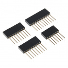
A SparkFun BlueSMiRF Silver connected to the Serial 1 Port using a 6-pin, right angle female header with the outermost pins removed.
The pins on the shield match up with any of our BlueSMiRF modules. For other wireless solutions, you may have to wire each pin manually as they may not match up exactly.
Particle Libraries and the Partilce IDE
The Particle team has created both an online and a desktop version of their programming IDE. The online version is referred to as Particle Build. The desktop version is referred to as Particle Dev. It can be downloaded here. Documentation on how to use Particle Dev can be found here. The libraries and example sketches presented throughout this tutorial will work in both versions, however, the means by which each is accomplished will vary slightly.
When dealing with many libraries, you may find it easier to use the Particle Dev desktop IDE as it is easier to add entire project folders. However, if you prefer to use the online IDE or are using a Linux computer, which does not have a desktop version of the IDE at this time, you can still follow along.
Once you have the IDE of your choice setup, visit GitHub, and download the SparkFun Photon Weather Shield Repository. You can also download the .zip file by clicking the link below.
SparkFun Photon Weather Shield Repository
Once the download is complete, open the folder, and navigate to the Firmware folder. Each example uses a variety of different libraries. There are too many to go over in detail here. However, they are all linked below if you would like to learn more about a given library.
- HTU21D Particle Library
- SparkFun MPL3115A2 Particle Library
- OneWire Particle Library
- Dallas Temperature Particle Library
- SparkFun Phant Particle Library
- SparkFun Serial Graphic LCD Particle Library
Each project folder contains the corresponding library files needed to compile that sketch. It’s redundant as far as storage is concerned, but it makes importing each project folder much easier.
Adding Projects to Particle Dev
To add a project folder to Particle Dev, simply click File -> Add Project Folder, and select the project of your choice.

Adding Projects to Particle Build
Unfortunately, there is no way to import project folders into the online IDE at this time, so each library will need to be added individually. Adding a library in Particle Build requires you to search for that library in their library manager. Once found, you can click the Include In App button to add that library to your project.

Each example will state which libraries are needed for it to work.
Now that you know how to work within the Particle IDE, lets upload some code!
Example 1: Getting Started & Reading the On-Board Sensors
For this first example, we’re going to keep it simple. This code will get data from the two on-board sensors and print that information to the Serial port. Your Photon will need to be plugged into a USB port on your computer in order to read the input in a Serial Terminal. You’ll need a Micro USB cable, which you should have if you bought Photon kit.
This first example will detail how to use each version of the Particle IDE. Each example after this will assume you know how to navigate each.
Particle Dev
Open Particle Dev. Click File -> Add Project Folder. Navigate to where you downloaded the SparkFun Photon Weather Shield repo, and select the ‘SparkFun_Photon_Weather_Basic’ folder. Click open, and the folder will be added to the left hand sidebar. You can also drang and drop folders into the IDE. The .ino file along with the library files will be avaialble here. Double-click the SparkFun_Photon_Weather_Basic.ino file to see the sketch.
Explore the sketch. Read the comments. Make any changes you want. Once you’re ready to upload, you’ll need to first select your target device. Click the crosshair looking symbol on the left hand menu to select your device.

You’ll be presented with a list of all your Particle devices. Select the correct target. Click the circle with a check mark to compile your code and check for any errors.

If everything compiles without error, click the lightning bolt symbol to upload you code.

Particle Build
Create a new App by typing a name in the ‘Current App’ field and pressing ‘Enter’.

When using Particle Build, you’ll need to add each library individually. Search for ‘sparkfun_mpl’ in the “Libraries” tab to find the SparkFun MPL3115A2 Particle Library. Once found, click on the library.

Select INCLUDE IN APP, and add it to your desired code file.

Any sketch using the external libraries needs to have the library “included” first.
Repeat the same process for the HTU21D Particle Library.

What You Should See
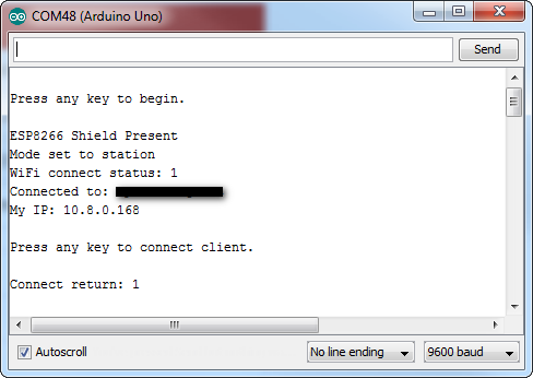
Once everything has uploaded correctly, open your favorite Serial Terminal program at 9600-8-N-1-NONE. Select the serial port your Photon has showed up as, and click connect. You should see something like the following print out in the window.

Example 2: Adding External Senors
This example will show you how to control any and all external senors attached to the Weather Shield including the Soil Moisture Sensor, Waterproof Temperature Sensor, and the Weather Meters.
To start, we’ll just add control of both the Soil sensors to our code, then we’ll add the Weather Meter code.
Soil Senors Example
Particle Dev
Open Particle Dev. Click File -> Add Project Folder. Navigate to where you downloaded the SparkFun Photon Weather Shield repo, and select the ‘SparkFun_Photon_Weather_Basic_Soil’ folder. Click open, and the folder will be added to the left hand sidebar. The .ino file along with the library files will be avaialble here. Double-click the SparkFun_Photon_Weather_Basic_Soil.ino file to see the sketch.
Select your target device, compile and upload the sketch.
Particle Build
Create a new App by typing a name in the ‘Current App’ field and pressing ‘Enter’.
Search for ‘onewire’ in the “Libraries” tab to find the OneWire Particle Library. Once found, click on the library.

Select INCLUDE IN APP, and add it to your desired code file.

Any sketch using the external libraries needs to have the library “included” first.
Repeat the same process for the Dallas Temperature Particle Library, as well as the SparkFun_MPL3115A2 library and HTU21D Library used in the previous example. You should have four libraries total for this example.

What You Should See
Once everything has uploaded correctly, open your favorite Serial Terminal program at 9600-8-N-1-NONE. Select the serial port your Photon has showed up as, and click connect. You should see something like the following print out in the window:

Click for a larger view.
Weather Meters
Building off the last two examples, we can complete the package by adding the weather meter code. The meters do not require any external libraries. However, if you are using the on-board sensors as well as the soil sensors, which is assumed in the example sketch, then you will need the four previous libraries we have used so far: OneWire, DallasTemperature, HTU21D, and the SparkFun_MPL3115A2 libraries.
Particle Dev
Open Particle Dev. Click File -> Add Project Folder. Navigate to where you downloaded the SparkFun Photon Weather Shield repo, and select the ‘SparkFun_Photon_Weather_Basic_Soil_Meters’ folder. Click open, and the folder will be added to the left hand sidebar. The .ino file along with the library files will be avaialble here. Double-click the SparkFun_Photon_Weather_Basic_Soil_Meters.ino file to see the sketch.
Select your target device, compile and upload the sketch.
Particle Build
The easiest way to go about this would be to use the app you made for the soil sensors and copy and paste this example of the previous sketch. Otherwise you’ll have to create a new app and add all the libraries again.
What You Should See
Once again, open your favorite Serial Terminal program at 9600-8-N-1-NONE. Select the serial port your Photon has showed up as, and click connect. You should see something like the following print out in the window:

Click for a larger view.
Example 3: Collecting Weather Data Online
Printing to the Serial Terminal is fun and all, but let’s get this thing on the Internet! One of the most common things you’ll want to do with the weather data you’re collecting is to store it someplace. You’re in luck! With our data.sparkfun.com service, aka Phant, you can store all the weather data on the cloud, for free! You can then pull that data into a multitude of programs and websites to manipulate and visualize your weather data however you like.
This example will show you how to store your weather data on data Phant using the SparkFun Phant Particle Library.
Pushing Data to data.sparkfun.com (Phant)
This example builds off the previous two. You should have the previous four libraries added to your app, as well as a new, fifth library, the SparkFun Phant Particle Library.

If you’re using Particle Dev, there is a project folder labeled SparkFun-Spark-Phant. Add it to Dev to quickly get started with this example. Open the SparkFun-Spark-Phant.ino example sketch.
You’ll need to create a data.sparkfun.com stream if you have not done so already. Details on how to do that can be found in our tutorial. Keep track our your public and private keys as well as the Field labels you choose.
With that info in hand, open the sketch and find the Phant variables. You’ll need to change these to match your stream’s keys.

You’ll also need to add each of the Fields you added when you created your stream. Make sure these match exactly.

What You Should See
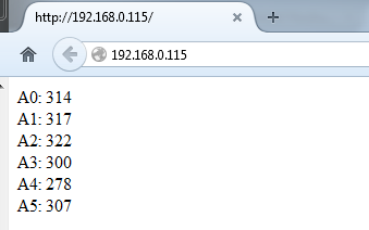
With your stream created and the sketch edited accordingly, you can now upload to the Photon. Once complete, you should begin to see data populate on your stream.

Click for a larger view.
You can now pull that data into any other device or service to organize however you see fit.
Pushing Weather Data to Wunderground
If you would like to upload your weather data to Wunderground, you can follow along with the WIMP Weather Station tutorial to learn how to accomplish the same with your Photon Weather Station.
Example 4: Internet-connected Weather Station
All we’ve learned so far has been to help prepare us for the challenging yet rewarding task of creating your own weather station connect to the Web. This example will build off all the previous examples. We’ll also be adding a Serial Graphic LCD connected to the Weather Shield via a Bluetooth connection so you can collect data online as well as having a monitor indoors that prints live weather data.
Required Materials
To follow along with this example, you’ll need a few more components. There are few different options for creating such a connection.


Configure the BlueSMiRFs to connect to one another automatically at 115200 baud. If you need help, we have a BlueSMiRF tutorial that covers that information. Connect one Bluetooth module to the Serial Graphic LCD Backpack, and connect the other to the Weather Shield. The LCD should also be set to 115200 baud.
A BlueSMiRF connected to the Serial 1 Port using a 6-pin, right angle female header with the outermost pins removed.

The Serial Graphic LCD Backpack connected to one of our discontinued BlueSMiRF modules with RP-SMA. Fortunately, the range on the BlueSMiRF Gold with Chip Antenna is very powerful.
If you’re using Particle Build, grab all the previous libraries plus a new one, the SparkFun Serial Graphic LCD Particle Library.

If you’re using Particle Dev, there is a project folder labeled SparkFun-Spark-Phant_LCD. Add it to Dev to quickly get started with this example. Open the SparkFun-Spark-Phant_LCD.ino example sketch.
What You Should See
If everything works out, you should see weather data print out on the LCD as well as post to Phant.

You now have a Internet-connected weather station! Once you have weather-proofed the electronics, as per our WIMP Weather Station tutorial, place it outside, and take it for a spin.

Resources and Going Further
Here are a few links that should help with any further questions you may have about the Photon Weather Shield:
- SparkFun Photon Weather Shield GitHub Repo– this is where to go for all the example code and hardware files.
- Particle Documentation Pages– go here to set up and configure your Photon (or other Particle devices)
- Particle Community Forum– anything that you couldn’t find in the docs should be easily found in the community forum. If you are having trouble, search this forum first, as many of the answers are there already.
And don’t forget about the other Photon shields in our lineup!


learn.sparkfun.com |CC BY-SA 3.0 | SparkFun Electronics | Niwot, Colorado