Introduction
The SparkFun Inventor’s Kit for Photon, also known as the SIK for Photon, is the latest and greatest in Internet of Things kits. Whether you’re a software developer just getting in to hardware, an electronics engineer learning software, or somewhere in between, this kit will help you get your projects hooked up to the Internet in no time.
For an overview of the Photon RedBoard and a preview of the kinds of experiments you’ll get to build with this kit, check out the video below.
Set Aside Some Time - Each experiment in this kit has two parts, with the second half usually containing an Internet-connected component. Please allow yourself ample time to complete each experiment. You may not get through all the experiments in one sitting. Please understand that the second half of each experiment is bonus material and relies on outside services, websites and technologies, to which some of you may not have access.
Included Materials
Here is a complete list of all the parts included in the SIK for Photon.
![Photon Inventor's Kit Parts]()
The SparkFun Inventor’s Kit for Photon Includes the following:
If, at any time, you are unsure which part a particular experiment is asking for, reference this section.
Suggested Reading
The following links are here to help guide you in your journey through the SIK for the Photon. Referencing these documents throughout this guide will help you get the most out of this kit.
- The Photon RedBoard Hookup Guide - This guide goes over the features of the Photon RedBoard in great detail, from the functions of each pin to a compare and contrast between the Photon RedBoard, the Photon, and the classic Arduino Uno.
- Photon Development Guide - Learn how to develop with your Photon or Photon RedBoard using the three different methods described in this tutorial.
- Getting Started with Particle - The Particle website has tons of great documentation to get you started in the world of IoT development.
Each experiment will also have a Suggested Reading section to aid you in understanding the components and concepts used in that particular experiment.
Using the Kit
Before embarking upon the experiments, there are a few items to cover first. If you have completed one of our other Inventor’s Kits before, you should already be familiar with most of the concepts in this section. If this is your first Inventor’s Kit, please read carefully to ensure the best possible SIK experience.
Photon RedBoard
The SparkFun Photon RedBoard is quite literally the brains of the SIK for Photon. Sporting an ARM Cortex M3 processor and a Broadcom WiFi controller, it is a powerful system rolled into one of the most common form-factors now found in embedded electronics. To learn more about the Photon RedBoard and all its functionality, visit the Photon Redboard Hookup Guide.
Base Plate
Building circuits can be a monumental task when you’ve never done so before. To make circuit development easier, we have included a baseplate onto which you can attach your breadboard and your Photon RedBoard.
To attach the breadboard, peel off the adhesive backing, and place the breadboard on the baseplate, making sure that the SparkFun logo and text on your breadboard all face the same direction.
To attach the Photon RedBoard, use the included screws and screwdriver to attach the board to the baseplate. Again, be sure that the text on the pins matches the directions of the breadboard text and the SparkFun logo. The USB connector should be pointing up when looking directly at the baseplate.
![base plate]()
Breadboard
Solderless breadboards are the go-to prototyping tool for those getting started with electronics. If you have never used a breadboard before, we recommend reading through our How to Use a Breadboard tutorial before starting with the experiments.
How to Use a Breadboard
Welcome to the wonderful world of breadboards. Here we will learn what a breadboard is and how to use one to build your very first circuit.
Jumper Wires
This kit includes twenty 6" long jumper wires terminated as male to male. Multiple jumpers can be connected next to one another on a 0.1" header or breadboard.
![jumpers]()
Each group of jumpers are connected to each other and can either be pulled apart in any quantity or kept whole based on you needs.
![peeling]()
Screwdriver
Last, we’ve included a pocket screwdriver set to aid you in any mechanical portions of this guide. Unscrew the cap on the tail end of the screwdriver to reveal the various tips that can be inserted into the head of the screwdriver.
![alt text]()
You will need to swap out tips for various tasks throughout this guide.
![alt text]()
Using the Particle IDE
If you’ve worked with Arduino or with our SparkFun Inventor’s Kit for Arduino, then you are familiar with the Arduino IDE, short for Integrated Development Environment. Particle has created their own cloud-based IDE, and they have adopted the Arduino language and syntax allowing you to move from an Arduino to the Photon and Photon RedBoard with ease.
Particle has written a great getting started guide for using their Web IDE, called Particle Build. You can read through their documentation by following the link below.
Getting Started with Particle Build
We have also written a Photon Development guide to help aid you in your experience. There are numerous ways to develop with the Photon and Photon RedBoard, and this guide covers the three most common methods: Particle Build, Particle Dev, and ARM GCC.
For the purposes of this guide, we recommend sticking to the online Particle Build IDE. However, once you feel comfortable using the Photon RedBoard, you are free to explore the other methods for development.
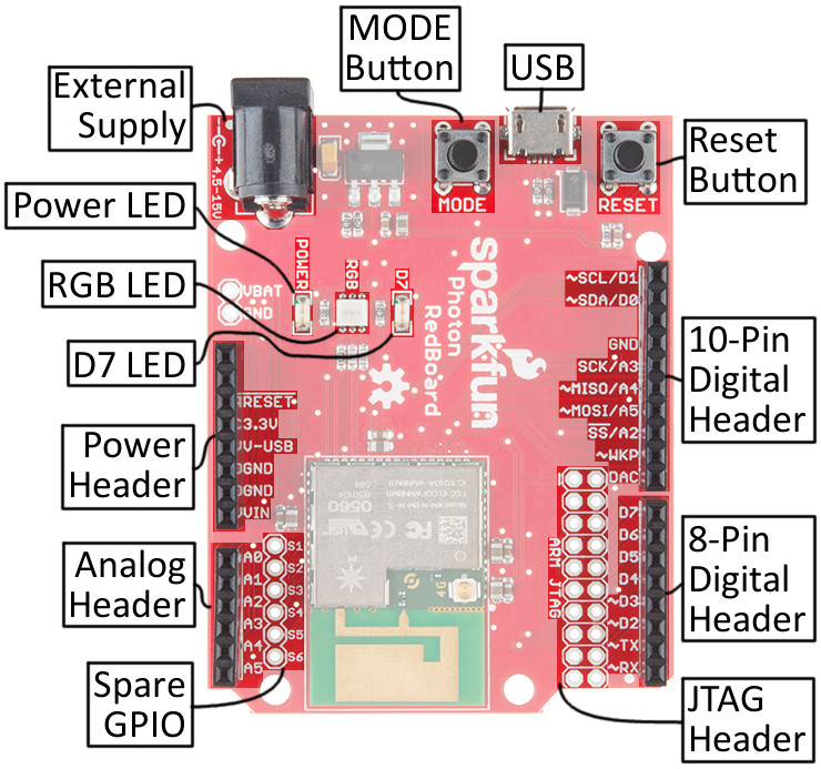
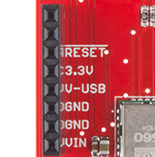
Getting Started with the Photon RedBoard
The Photon RedBoard can be powered over either USB (using the included Micro-B Cable) or with a 4.5-15V barrel jack power supply (like either our 5V and 9V wall warts). To begin using your Photon RedBoard, plug it in!
![USB plugged into Photon RedBoard]()
The red “POWER” LED should illuminate to indicate the Photon RedBoard is on. Once that’s verified, it’s time to set up WiFi.
Configuring WiFi, Connecting to Your Particle Account
To use the Particle cloud – and their online IDE – you’ll need a Particle account. Head over to build.particle.io to sign up, if you haven’t already.
Create a Particle Account!
When you power on a Photon RedBoard for the first time, it should boot up into listening mode– indicated by a blinking, blue LED. It’ll remain in listening mode until configured with your WiFi network and password.
There are a handful of ways to configure a Photon’s WiFi credentials, including with the Particle smartphone app (iOS8+ or Android), or through a serial terminal. Unless you’re very comfortable with serial terminals– or just don’t have a smartphone nearby – we recommend using the app.
Both setup methods are described below, click one of the buttons to expand your section of interest:
Step 1: Download the Particle App
The Partice app is available for both iOS (8.0 and up) and Android phones: iPhone | Android.
Step 2: Follow the in-app directions to connect your Photon
1. After opening the app, press "Get Started", to arrive at the device list screen. Scroll to the bottom and select Setup a Photon...
![]()
Select "Setup a Photon..." to begin setting up your Photon RedBoard.
2. Verify that your Photon RedBoard's RGB LED is blinking blue, then select "READY" on the next screen.
3. Navigate to your phone's WiFi settings and find a network named something like Photon-9XYZ (with a random set of four characters as the suffix). Select it.
![]()
Your Phone should find a network name prefaced with "Photon-", connect to it.
4. Switch back to the Particle app. After a few seconds, the app should present you with a list of WiFi networks. Select the network you want to connect your Photon RedBoard to. On the next screen type in the network's password.
5. The penultimate screen will show the Photon RedBoard's progress as it connects to your WiFi network and the Particle cloud.
6. Finally, create a name for your Photon. You can go with Particle's (wonderfully random) suggestion, or one of your own.
![]()
If, for some reason or another, you can't use the Particle app to commision your Photon RedBoard, one alternative is using a Serial Terminal.
An alternative to this method – one that doesn't require serial terminal-ing – is
Particle CLI. After installing particle CLI you can use the
particle setup command to run through device setup. More information on that
here.
1. Open a serial terminal program (check out our Serial Terminal Basics tutorial for suggestions) to your Photon's serial port. On Windows, the port should look something like COM#. On Mac, the port will be something like /dev/tty.usbmodem####.
2. Type i to get your Photon's Device ID. Copy it down – at least temporarily.
3. Type w to enter WiFi configuration. Then follow along with the prompts to enter you WiFi network's name and password.
![]()
Type 'i' to get your Photon's Device ID, then 'w' to configure its WiFi.
4. Go to the Particle Build IDE. Create an account if you haven't already, or log in.
5. Hop over to the "Devices" tab. Select Add New Device, and paste in your Photon RedBoard's Device ID.
![]()
Paste your Photon's Device ID into the Build IDE.
6. Name your new Photon RedBoard
7. Your Photon RedBoard will initially appear under the "Other" section, but after reloading the IDE, it should find its home under the "P1s" section.
Experiment 1: Hello World, Blink an LED
Some of the experiments will have two parts. The first part, will focus on teaching you about electronic concepts and technologies and how to build a circuit around those. The second part is bonus material showing you how to connect your circuit to the Internet or creating a more complex circuit. You will be able to complete part one of each experiment with the included parts. However, the second half of each experiment relies on outside services, websites and technologies, some of which you may not have access to or may not want to engage in. Should part two of a particular experiment not interest you, you may move on to the next experiment.
Introduction
LEDs (light-emitting diodes) are small, powerful lights that are used in many different applications. To start off the SIK for Photon, we will work on blinking an LED using a digital output. Chances are you have blinked an LED before, or perhaps this is your first time – but have you turned on an LED with the Internet? Blinking an LED is the most basic “Hello World” test for hardware, but now we’re going to be saying “Hello Internet.” This experiment will also walk you through uploading your first sketch with the Particle IDE.
Parts Needed
You will need the following parts:
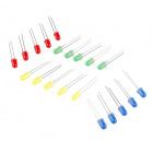
- 1x LED (Choose any color in the bag full of LEDs)
- 1x 330Ω Resistor
- 2x Jumper Wires
Using a Photon by Particle instead or you don't have the kit? No worries! You can still have fun and follow along with this experiment. We suggest using the parts below:
Out of stock
COM-12062
We all know that you can never get too many LEDs. Don't worry, we've got you covered. This is a pack of basic red, yellow, bl…
5In stock
PRT-12795
These are 6" long jumper wires with male connectors on both ends. Use these to jumper from any female header on any board, to…
In stock
COM-11507
1/6 Watt, +/- 5% tolerance PTH resistors. Commonly used in breadboards and perf boards, these 330Ohm resistors make excellent…
1Suggested Reading
Before continuing on with this experiment, we recommend you be familiar with the concepts in the following tutorial:
- What is a Circuit?– This tutorial will explain what a circuit is, as well as discuss voltage in further detail.
- Voltage, Current, Resistance, and Ohm’s Law– Learn the basics of electronics with these fundamental concepts.
- LEDs (Light-emitting Diodes)– LEDs are found everywhere. Learn more about LEDs and why they are used in some many products all over the world.
- Resistors– Why use resistors? Learn more about resistors and why they are important in circuits like this one.
- Polarity– Polarity is a very important characteristic to pay attention to when building circuits.
Hardware Hookup
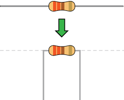
Ready to party? Components like resistors need to have their legs bent into 90° angles in order to correctly fit the breadboard sockets. You can also cut the legs shorter to make them easier to work with on the breadboard.
![Bent resistor]()
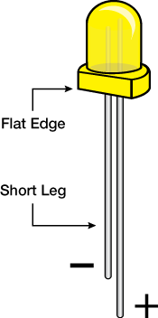
Pay close attention to the LED. The negative side of the LED is the short leg, marked with a flat edge.
![LED drawing]()
Each experiment will have a Fritzing hook-up diagram. Connect the components to the breadboard and Photon RedBoard by following the Fritzing diagram below:
Pay special attention to the component’s markings indicating how to place it on the breadboard. Polarized components can only be connected to a circuit in one direction. Orientation matters for the following component:
LED ![Photon Particle Blink LED]()
Having a hard time seeing the circuit? Click on the Fritzing diagram to see a bigger image.
All jumper wires work the same. They are used to connect two points together. All the experiments will show the wires with different colored insulations for clarity, but using different combinations of colors is completely acceptable.
Be sure to the polarity on the LED is correct. The longer lead should be connected to D0.
Photon Code
Now to the exciting part! You’ll need to go to the Particle Build IDE (preferably on another tab or window) to get started. If you are not familiar with the Particle Build IDE, please refer to the Particle Build IDE documentation or the Particle Build IDE overview in the beginning of this guide.
Using an online IDE might be little different at first for some users, but it ends up being fantastic. You can program your Photon from anywhere in the world as long as you have an Internet connection.
Double check your Photon RedBoard’s RGB LED is breathing cyan. If it is, then your Photon RedBoard is connected to the Internet and ready to go. If your Photon RedBoard is not breathing cyan, please refer to the Connecting your Photon to WiFi documentation. If you go to the navigation bar, click on Devices to see if your Photon RedBoard is connected.
![Screen shot of devices for Photon RedBoard.]()
There will be a breathing cyan dot next to your Photon RedBoard in the Devices section.
For each experiment, we recommend creating a new app. Go to the Code section in the navigation bar on the left. The hit the CREATE NEW APP button. After typing in the name, you can hit enter.
![Name app]()
When you create a new app, particle build creates an .ino file and renames the tab in the Particle Build editor.
Let’s add the code! Copy and paste the code below into the in Particle Build editor. You can simply hit the COPY CODE button below and paste (Right-click then click Paste or Command + V) into the Particle Build Editor.
language:c
/*  SparkFun Inventor's Kit for Photon
    Experiment 1 - Part 1: Hello World Blink an LED
    This sketch was written by SparkFun Electronics
    August 31, 2015
    https://github.com/sparkfun

    This is a simple example sketch that turns on an LED
    for one second, off for one second, and repeats forever.

    Development environment specifics:
    Particle Build environment (https://www.particle.io/build)
    Particle Photon RedBoard
    Released under the MIT License(http://opensource.org/licenses/MIT)
*/

int led = D0; // LED is connected to D0

// This routine runs only once upon reset
void setup()
{
  pinMode(led, OUTPUT); // Initialize D0 pin as output
}

// This routine loops forever
void loop()
{
  digitalWrite(led, HIGH);  // Turn ON the LED
  delay(1000);              // Wait for 1000mS = 1 second
  digitalWrite(led, LOW);   // Turn OFF the LED
  delay(1000);              // Wait for 1 second
}
Once you’ve pasted the code into the window, let’s get in the habit of checking our code. Hit Verify (circle icon with a check mark in the top left of the Particle Build’s IDE navigation bar) to check if there is any errors in the code. Next, hit Save (folder icon) to save our code, so we can come back to the code later if we want to.
Drum roll please! Hit Flash (lightning bolt icon) to load the code onto the Photon RedBoard.
What You Should See
Once you click Flash, you should see your Photon RedBoard flash magenta, followed by green, and then back to breathing Cyan. Now, your LED should be blinking. You’ve just wirelessly programmed your Photon RedBoard to blink an LED, from the cloud!
![Photon RedBoard LED hookup]()
Great job on successfully uploading your first sketch. If you want to learn how blink an LED with the Tinker mobile app, you can head to part 2 of this experiment!
Code to Note
Variables
A variable can be a number, a character, and even a string of characters. We’ll often use variables to store numbers that change, such as measurements from the outside world, or to make a sketch easier to understand (sometimes a descriptive name makes more sense than looking at a number).
Variables can be different “data types”, which is the kind of number we’re using (can it be negative? Have a decimal point?) We’ll introduce more data types later, but for the moment we’ll stick with good old “integers” (called “int” in your sketch). Integers are whole numbers (0, 3, 5643).
You must “declare” variables before you use them, so that the computer knows about them. Here we’ll declare a integer variable, and at the same time, initialize it to specific values. We’re doing this so that further down, we can refer to the pin by name rather than number.
Note that variable names are case-sensitive! If you get an “(variable) was not declared in this scope” error, double-check that you typed the name correctly.
Here we’re creating a variable called “led” of type “int” and initializing it to have the value “0”:
int led = D0;
The Photon RedBoard has digital input/output pins. These pins can be configured as either inputs or outputs. This is declared with a built-in function called pinMode(). The pinMode() function takes two values, which you type in the parenthesis after the function name. The first value is a pin number (or variable representing a pin number), and the second value declares how the pin behaves, usually as some sort of INPUT or OUTPUT.
Here we’ll set up pin 0 (the one connected to a LED) to be an output. We’re doing this because we need to send voltage “out” of the Photon RedBoard to light up the LED.
pinMode(led, OUTPUT);
When you’re using a pin as an OUTPUT, you can command it to be HIGH (output 3.3 volts in this case), or LOW (output 0 volts).
digitalWrite(led, HIGH);
For more info on the types of PinModes available, visit the Particle Documentation.
Comments
There are different ways to make comments in your code. Comments are a great way to quickly describe what is happening in your code.
// This is a comment - anything on a line after "//" is ignored
// by the computer.
/* This is also a comment - this one can be multi-line, but it
must start and end with these characters */
Troubleshooting
Code refuses to flash– Try putting your Photon RedBoard into Safe Mode. Then, hit Flash. Sometimes to get your Photon RedBoard breathing cyan again, unplugging from USB and replugging back can get your board connecting to WiFi again. Please keep in mind if you just starting working with the Photon RedBoard it might take a couple minutes for the firmware to upload when first connected to the Internet.
LED isn’t blinking– Try checking your connections again. Make sure the positive side of the LED is connected to D0. It is really easy to put the jumper wire in the wrong hole on a breadboard.
Photon RedBoard RGB isn’t doing anything– Don’t worry! We have an awesome tech support staff to help you out if there is something wrong. Please contact our tech support team.
Part 2: Blink an LED with Tinker
Tinker is a mobile app for iPhone or Android smartphones that makes it easy to control your digital and analog pins on your Photon or Photon RedBoard.
First you will need to download the app on your smartphone.
iPhone users
Android users
Windows users– Unfortunately, this extra feature is only for iOS and Android devices. Don’t worry, this is the only bonus material that uses with the Tinker app.
Non-smartphone users– Most of us would love to go back the happy memories of not owning a smartphone and not getting 50+ alerts each day. We applaud you! We also might secretly envy you. Unfortunately, this bonus material isn’t going to be your cup of tea. Don’t worry, this is the only bonus material that uses with the Tinker app.
When the app is done installing on your phone, you will need to sign in with your login information (the same as the Particle website). After logging in, you will see a list with all your devices.
![Photon Device ID]()
Clicking on the more icon (three dots) next to the online dot, gives you more options from which to choose. For example, you can rename your board here. We suggest naming your Photon RedBoard with unique names. When you start having a lot of Photons and demos going at once, it is hard to remember which is which.
When clicking on the more icon, do not choose Re-Flash Tinker. At the moment, it will re-flash your board with firmware that isn't the latest and greatest with the Photon RedBoard!
When you click over the name of the Photon RedBoard you want to work with, you will see a new screen with a list of the different pins you can control.
![List of Photon RedBoard pins]()
First, click the circle that is label with D0. Anytime you want to work with a pin, you will need to select it first. You can select multiple pins at a time.
![alt text]()
You’ll notice that you have a couple different options. For this example, we are going to control the LED ON and OFF, by clicking on digitalWrite.
![alt text]()
New Photon Code (There is none!)
What is great about this mobile app, you do not have to do any coding! Once you are signed into Tinker, you can start playing with the pins.
What You Should See
To turn the LED ON/HIGH, click the circle labeled D0 again. It should show the LED turn on.
![alt text]()
To turn the LED OFF/LOW, click the circle labeled D0 again. It should show the LED turn off.
![alt text]()
This is a super fun and easy way to control an LED or any other hardware. To reset all the pins and start fresh, click on the more icon (three dots) on the top right. You will see Reset all pin functions option.
Dig into the app a little bit more! What happens when you click D0 and choose analogWrite? What happens when you select D7 instead? HINT: Take at look at your board!
Troubleshooting
The app froze– If your app ever stops on you, close out the app and reopen. Report bugs to the wonderful Particle team on their forums.
I have a Windows phone– Unfortunately, this extra feature is only for iOS and Android devices. Don’t worry, this is the only bonus material that uses with the Tinker app.
There is a yellow circle and it says it is non-tinker– All Photon RedBoards were shipped out with the latest firmware that works with Tinker. If you get the yellow circle, it means the firmware on your RedBoard was re-flashed with old firmware. You will need to flash with the latest firmware. Please follow the directions here for now. We are working with Particle to make sure the Tinker app is pushing the latest firmware when re-flashing.
Introduction
Now that you have conquered blinking an LED and know what an output is, it is time to learn inputs!
In this circuit, we’ll be introducing one of the most common and simple inputs – a push button – by using a digital input. Just like the LED, the push button is a basic component that is used in almost everything. The way a push button works with your Photon is that when the button is pushed, the voltage goes LOW. You Photon reads this and reacts accordingly. RedBoard Photon has internal pull-ups resistor, which keeps the voltage HIGH when you’re not pressing the button.
Parts Needed
You will need the following parts:
- 1x LED
- 1x Push Button
- 1x 330Ω Resistor
- 4x Jumper Wires
Using a Photon by Particle instead or you don't have the kit? No worries! You can still have fun and follow along with this experiment. We suggest using the parts below:
Out of stock
COM-12062
We all know that you can never get too many LEDs. Don't worry, we've got you covered. This is a pack of basic red, yellow, bl…
5In stock
COM-10302
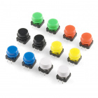
These tactile buttons are great for all sorts of projects. This assortment comes with 2 of each of 6 different colors for a t…
In stock
PRT-12795
These are 6" long jumper wires with male connectors on both ends. Use these to jumper from any female header on any board, to…
In stock
COM-11507
1/6 Watt, +/- 5% tolerance PTH resistors. Commonly used in breadboards and perf boards, these 330Ohm resistors make excellent…
1Suggested Reading
- Switch Basics– The push button is a momentary switch. Momentary switches are switches which only remain in their on state as long as they’re being actuated (pressed, held, magnetized, etc.). Learn more about the different types of switches.
- Pull-up Resistors - Pull-up resistors are very common when using microcontrollers (MCUs) or any digital logic device. This tutorial will explain when and where to use pull-up resistors, then we will do a simple calculation to show why pull-ups are important.
How to use logic like a Vulcan:
One of the things that makes the Photon RedBoard so useful is that it can make complex decisions based on the input it’s getting. For example, you could make a thermostat that turns on a heater if it gets too cold, or a fan if it gets too hot, and it could even water your plants if they get too dry. In order to make such decisions, the particle environment provides a set of logic operations that let you build complex “if” statements. They include:
| == | EQUIVALENCE | A == B is true if A and B are the SAME. |
|---|
| != | DIFFERENCE | A != B is true if A and B are NOT THE SAME. |
|---|
| && | AND | A && B is true if BOTH A and B are TRUE. |
|---|
| || | OR | A || B is true if A or B or BOTH are TRUE. |
|---|
| ! | NOT | !A is TRUE if A is FALSE.!A is FALSE if A is TRUE. |
|---|
You can combine these functions to build complex if() statements. For example:
language:c

if ((mode == heat) && ((temperature < threshold) || (override == true)))
{
digitalWrite(HEATER, HIGH);
}
…will turn on a heater if you’re in heating mode AND the temperature is low, OR if you turn on a manual override. Using these logic operators, you can program your Photon RedBoard to make intelligent decisions and take control of the world around it!
Hardware Hookup
Your kit comes with a bunch of different color push button. All push buttons behave the same, so go ahead and use your favorite color! Add the push button to the same LED circuit from the first experiment. Follow the Fritzing diagram below.
Pay special attention to the component’s markings indicating how to place it on the breadboard. Polarized components can only be connected to a circuit in one direction. Orientation matters for the following component:
LED ![Photon RedBoard Button and LED hook-up]()
Having a hard time seeing the circuit? Click on the Fritzing diagram to see a bigger image.
Photon Code
language:c
/*  SparkFun Inventor's Kit for Photon
    Experiment 2 - Part 1: With a Touch of a Button
    This sketch was written by SparkFun Electronics
    August 31, 2015
    https://github.com/sparkfun

    This is a simple example sketch that turns on an LED
    when pushing down on the push button

    Development environment specifics:
    Particle Build environment (https://www.particle.io/build)
    Particle Photon RedBoard
    Released under the MIT License(http://opensource.org/licenses/MIT)
*/

int led = D0; // LED is connected to D0
int pushButton = D2; // Push button is connected to D2

// This routine runs only once upon reset
void setup()
{
  pinMode(led, OUTPUT); // Initialize D0 pin as output
  pinMode(pushButton, INPUT_PULLUP);
  // Initialize D2 pin as input with an internal pull-up resistor
}

// This routine loops forever
void loop()
{
  int pushButtonState;

  pushButtonState = digitalRead(pushButton);

  if(pushButtonState == LOW){ // If we push down on the push button
    digitalWrite(led, HIGH);  // Turn ON the LED
  }
  else
  {
    digitalWrite(led, LOW);   // Turn OFF the LED
  }

}
What You Should See
When you hold down the push button, those warm fuzzy feelings from the first experiment should happen again, and the LED should shine brightly. The LED will be off when the button is released.
![Photon RedBoard Button Plus LED hookup]()
Press down on the push button to see the LED light up
Code to Note
pinMode(pushButton, INPUT_PULLUP);
The digital pins can be used as inputs as well as outputs. Before you do either, you need to tell the Photon which direction you’re going. Normally, with push buttons we would use a pull-up resistor. However, you can program the Photon RedBoard to use its internal pull-up and pull-down resistors.
pushButtonState = digitalRead(pushButton);
To read a digital input, you use the digitalRead() function. It will return HIGH if there’s 5V present at the pin, or LOW if there’s 0V present at the pin.
if(pushButtonState == LOW)
Because we’ve connected the button to GND, it will read LOW when it’s being pressed. Here we’re using the “equivalence” operator (“==”) to see if the button is being pressed.
Troubleshooting
If nothing is happening when holding down the push button, don’t panic! Double check your jumper wire and LED connections. It is easy to miss a jumper wire or two.
Code refuses to flash – Try putting your Photon RedBoard into safe mode. Then, hit Flash. Sometimes to get your Photon RedBoard breathing cyan again, unplugging from USB and replugging back can get your board connecting to WiFi again. Please keep in mind if you just starting working with the Photon RedBoard it might take a couple minutes for the firmware to upload when first connected to the Internet.
Part 2: Control the Internet with IFTTT and Push Button
Have you ever wanted to control something on the Internet with a touch of a button? How about having a button that orders new laundry detergent when pressed? Okay, that has already been done with Amazon Dash Button. However, you can make one too! For the second part of this experiment, we are going to use IFTTT to send an email when the push button is pressed.
A fun feature of the Photon RedBoard is that it works with Particle’s IFTTT channel. IFTTT is short for “if this then that.” It is a free site that makes connecting different popular apps or products really easy and fast!
Let’s get started!
New Photon Code
language:c
/*  SparkFun Inventor's Kit for Photon
    Experiment 2 - Part 2: Control the Internet with IFTTT and Push Button
    This sketch was written by SparkFun Electronics
    August 31, 2015
    https://github.com/sparkfun

    This is a simple example sketch that sends an email
    with IFTTT when the push button is pressed

    Development environment specifics:
    Particle Build environment (https://www.particle.io/build)
    Particle Photon RedBoard
    Released under the MIT License(http://opensource.org/licenses/MIT)
*/

int led = D0; // LED is connected to D0
int pushButton = D2; // Push button is connected to D2

// This routine runs only once upon reset
void setup()
{
  pinMode(led, OUTPUT); // Initialize D0 pin as output
  pinMode(pushButton, INPUT_PULLUP);
  // Initialize D2 pin as input with an internal pull-up resistor
}

// This routine loops forever
void loop()
{
  int pushButtonState;

  pushButtonState = digitalRead(pushButton);

  if(pushButtonState == LOW){ // If we push down on the push button
    digitalWrite(led, HIGH);  // Turn ON the LED
    Spark.publish("pushButtonState","Pressed",60,PRIVATE);
    // Add a delay to prevent getting tons of emails from IFTTT
    delay(5000);
  }
  else
  {
    digitalWrite(led, LOW);   // Turn OFF the LED
  }

}
Code to Note
Spark.publish("pushButtonState", "Pressed",60,PRIVATE);
What is great about IFTTT is that you do not need a lot of extra code. This is the only piece of code we added. Visit the Spark.publish() page to learn more.
Setup IFTTT
Now that the code is loaded on your Photon RedBoard, we can jump into setting up IFTTT.
Sign up, or log into IFTTT, and activate your account from your email address. For this experiment we are going to create an IF recipe. The IF recipe is connecting two different apps and products in an if this then that statement. Click on My Recipe on the top navigation bar on the IFTTT site.
Follow the 7 steps below to create an IF recipe.
1: This
Click on this
![alt text]()
Find and select the Particle Channel. You will need to connect to the Particle channel.
![alt text]()
2: Choose a Trigger
Selected New event published
![alt text]()
3: Complete Trigger Fields
This is where you will enter the published event name. Type in pushButtonState in the If (Event Name) field. Go ahead and select your personal Photon RedBoard from the drop down menu.
![alt text]()
4: That
Click on the that button and find the Email Channel.
![alt text]()
Remember, your Photon RedBoard has the unique name you gave it and will show up differently then the above image.
![alt text]()
5: Choose an Action
Depending on what Channel you are using, there might be one or more different actions you can choose from. For this experiment, we will send an email.
![alt text]()
6: Complete Action Fields
You can customize what you want to see in the subject and body of your email.
![alt text]()
7: Create and connect
Name your recipe and hit Create Recipe.
![alt text]()
You’ve just created your first IFTTT recipe!
What You Should See
When you push down on the button, an email will send! You might have allow the gearworks of the internet to churn for a minute or two, but you should be able to see a new email. If you don’t feel like waiting, go ahead and click on the refresh-looking icon, named “Check Recipe now”.
You might have noticed there’s a vast amount of options for creating recipes. The possibilities are endless! Using the same code, here are a few more examples on what you can do:
- Post on social media and websites like Facebook, Twitter, Reddit, GitHub, Pinterest, Tumblr, and more!
- There are tons of products you might already use that have their own Channels. Including appliances and other home products
- Send a text message
- Shop at different sites
Troubleshooting
- Not seeing the email? A lot of people have multiple email addresses. Double check the same email you used to sign up for IFTTT. There is a Check Recipe now button for testing your recipes. This can be found under the My Recipes page.
- Still not working? Try redoing the IFTTT recipe again or check for typos.
Experiment 3: Houseplant Monitor
Introduction
This experiment uses a soil moisture sensor to allow you to monitor your houseplants. The first half of the experiment will introduce the concept of Analog Inputs, which allow us to read values that vary between two known thresholds rather than just being a HIGH or LOW digital value. You will use a built in Analog-to-Digital Converter on the Photon RedBoard to read the analog value coming from the soil moisture sensor. In the second half, we will expose that analog variable to the Particle Cloud so that other online applications can request the current moisture content and send you notifications when your plant needs watering.
Parts Needed
You will need the following parts:
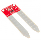
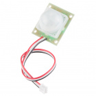
- 1x Soil Moisture Sensor
- 3x Jumper Wire
Using a Photon by Particle instead or you don't have the kit? No worries! You can still have fun and follow along with this experiment. We suggest using the parts below:
In stock
SEN-13322
The SparkFun Soil Moisture Sensor is a simple breakout for measuring the moisture in soil and similar materials. The soil moi…
1In stock
PRT-12795
These are 6" long jumper wires with male connectors on both ends. Use these to jumper from any female header on any board, to…
In stock
PRT-08235
Screw Terminals with 3.5mm pitch pins. Comes in 2 or 3 positions and have the really cool feature of slide-locking together t…
Tools Needed
You will need the screwdriver included in the Photon SIK. Find the second smallest flathead head tip, labeled CR-V 2.0, and insert it into the tip of the screwdriver.
Suggested Reading
Before continuing on with this experiment, we recommend you be familiar with the concepts in the following tutorials:
Hardware Hookup
Hook up your circuit as pictured below:
![Experiment 3 Diagram]()
Having a hard time seeing the circuit? Click on the Fritzing diagram to see a bigger image.
The easiest way to connect the soil moisture sensor to the RedBoard is to insert one end of each jumper wire into the 3-pin screw terminal attached to the soil sensor, and then screw each pin down until the jumper wire is secured and won’t pull out of the screw terminal.
![jumpers screw terminal]()
Photon Code
language:c
/*  SparkFun Inventor's Kit for Photon
    Experiment 3 - Part 1: LED Houseplant Monitor
    This sketch was written by SparkFun Electronics
    Joel Bartlett <joel@sparkfun.com>
    August 31, 2015
    https://github.com/sparkfun/Inventors_Kit_For_Photon_Experiments

    This application monitors the moisture level of your houseplant
    and turns the RGB LED red when the plant needs watered.
    Development environment specifics:
    Particle Build environment (https://www.particle.io/build)
    Particle Photon RedBoard
    Released under the MIT License(http://opensource.org/licenses/MIT)
*/
int val = 0;//variable to store soil value
int soil = A2;//Declare a variable for the soil moisture sensor
int soilPower = D6;//Variable for Soil moisture Power
//Rather than powering the sensor through the V-USB or 3.3V pins,
//we'll use a digital pin to power the sensor. This will
//prevent oxidation of the sensor as it sits in the corrosive soil.

void setup()
{
Serial.begin(9600);   // open serial over USB

pinMode(soilPower, OUTPUT);//Set D7 as an OUTPUT
digitalWrite(soilPower, LOW);//Set to LOW so no power is flowing through the sensor
}

void loop()
{
Serial.print("Soil Moisture = ");
//get soil moisture value from the function below and print it
Serial.println(readSoil());

delay(1000);//take a reading every second
//This time is used so you can test the sensor and see it change in real-time.
//For in-plant applications, you will want to take readings much less frequently.

    //If your soil is too dry, turn on Red LED to notify you
    //This value will vary depending on your soil and plant
    if(readSoil() < 200)
    {
      // take control of the RGB LED
      RGB.control(true);
      RGB.color(255, 0, 0);//set RGB LED to Red
    }
    else
    {
      // resume normal operation
      RGB.control(false);
    }
}
//This is a function used to get the soil moisture content
int readSoil()
{
    digitalWrite(soilPower, HIGH);//turn D6 "On"
    delay(10);//wait 10 milliseconds
    val = analogRead(soil);
    digitalWrite(soilPower, LOW);//turn D6 "Off"
    return val;
}
What You Should See
Once the code is uploaded to your Photon RedBoard, open your favorite Serial Terminal program. Connect to the Photon RedBoard. You should see soil moisture data begin to stream in the window.
![Soil Moisture Readings]()
Pressing your finger across the two prongs at varying pressures results in different moisture readings.
When the sensor detects very little moisture, the RGB LED on the Photon RedBoard will turn Red, notifying you that your plant needs watered. When the moisture level is satisfactory, the LED will breathe cyan, as usual.
![alt text]()
An exposed sensor should read close to zero, producing Red on the RGB LED.
Code to Note
Serial
Among other things, this example introduces serial communication with functions like Serial.begin() and Serial.print(). To initialize a serial interface, call Serial.begin([baud]) where [baud] sets the baud rate of the interface. In this example, we set the baud rate to 9600bps – a reliable (if slow) standard rate – in the setup() function:
language:c
void setup()
{
    ...
    Serial.begin(9600); // Start the serial interface at 9600 bps
    ...
}
To send data out of a serial interface, use either Serial.print(), Serial.println(), or Serial.write(). This example only uses the first two.
language:c
Serial.print("Soil Moisture = ");
//get soil moisture value from the function below and print it
Serial.println(readSoil());
For more information on Serial functions, check out Particle’s reference documentation.
Functions
int readSoil() is a user-made function. As with any other object-oriented language, you can declare your own functions that can be passed and can return different types of variables.
This function has no parameters passed to it, but it does return the soil moisture value as an integer (INT). You can create your own functions to accomplish tasks that you do not want to type out over and over again. Instead, you can call that function anywhere you would have written all that other code.
Troubleshooting
- Configuring the soil sensor can take a little trial and error. Different soils and moisture levels will result in different data. To get good values on which to base your plant’s condition, it best to take a reading when it is is as dry as possible without jeopardizing the plant’s well being. Take another reading after you’ve recently watered the plant to get your upper threshold. You can then adjust the code accordingly.
Part 2: Spark Variables
Being notified visually that your plant needs watered is useful, but what about when you leave for a week? How will you know if your plant is happy and thriving while you’re gone? One way to give you a view into your plants status is to use the spark.variable function, which is a built-in feature of the Particle firmware. This second example will use this feature to allow you to check the status of your plant anywhere that you have an Internet connection.
New Photon Code
Copy, paste and upload this new sketch. You’ll notice not much has changed. The Spark.variable("soil", &soil, INT); line is the only new addition.
language:c
/*  SparkFun Inventor's Kit for Photon
    Experiment 3 - Part 2: Internet Houseplant Monitor
    This sketch was written by SparkFun Electronics
    Joel Bartlett <joel@sparkfun.com>
    August 31, 2015
    https://github.com/sparkfun/Inventors_Kit_For_Photon_Experiments

    This application monitors the moisture level of your houseplant
    and exposes that data to be monitored via the Internet.
    Development environment specifics:
    Particle Build environment (https://www.particle.io/build)
    Particle Photon RedBoard
    Released under the MIT License(http://opensource.org/licenses/MIT)
*/
int val = 0;//variable to store soil value
int soil = A2;//Declare a variable for the soil moisture sensor
int soilPower = D6;//Variable for Soil moisture Power
//Rather than powering the sensor through the V-USB or 3.3V pins,
//we'll use a digital pin to power the sensor. This will
//prevent oxidation of the sensor as it sits in the corrosive soil.

void setup()
{
Serial.begin(9600);   // open serial over USB

pinMode(soilPower, OUTPUT);//Set D7 as an OUTPUT
digitalWrite(soilPower, LOW);//Set to LOW so no power is flowing through the sensor

//This line creates a variable that is exposed through the cloud.
//You can request its value using a variety of methods
Spark.variable("soil", &val, INT);
}

void loop()
{
Serial.print("Soil Moisture = ");
//get soil moisture value from the function below and print it
Serial.println(readSoil());

delay(1000);//take a reading every second
//This time is used so you can test the sensor and see it change in real-time.
//For in-plant applications, you will want to take readings much less frequently.

    //If your soil is too dry, turn on Red LED to notify you
    //This value will vary depending on your soil and plant
    if(readSoil() < 200)
    {
      // take control of the RGB LED
      RGB.control(true);
      RGB.color(255, 0, 0);//set RGB LED to Red
    }
    else
    {
      // resume normal operation
      RGB.control(false);
    }
}
//This is a function used to get the soil moisture content
int readSoil()
{
    digitalWrite(soilPower, HIGH);//turn D6 "On"
    delay(10);//wait 10 milliseconds
    val = analogRead(soil);
    digitalWrite(soilPower, LOW);//turn D6 "Off"
    return val;
}
What You Should See
If you haven’t already, place your sensor in the plant you would like to monitor.
![alt text]()
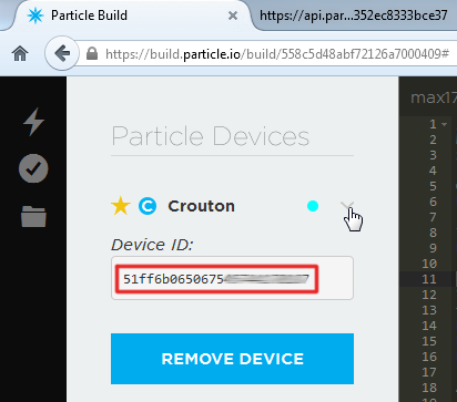
You can open the serial terminal to see the soil moisture value, as in the previous example. However, you can now also request that same value through the web. In order to do so, you’ll need your Photon’s device ID as well as your account’s access token. The device ID can be found in Particle Build by clicking the ‘>’ next to your device name.
![Particle Device ID]()
Find your Device ID under the “Devices” tab, by clicking the carrot next to your Photon.
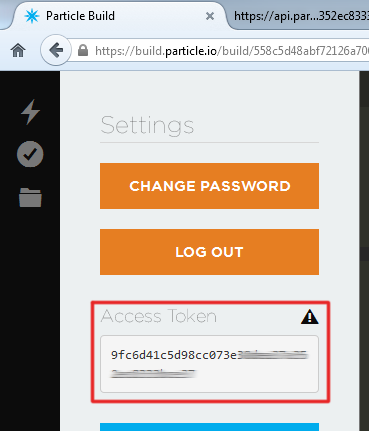
Your access token can be found under the “Settings” tab.
![Access Token]()
Find your access token under the “Settings” tab.
Armed with those long strings of hex characters, open a new browser tab and navigate to:
https://api.particle.io/v1/devices/DEVICE_ID/soil?access_token=ACCESS_TOKEN
Make sure to sub in the proper values for DEVICE_ID and ACCESS_TOKEN.
TIP: You can also use the Name of your device instead of the device ID.
If everything was entered correctly, you should see something like this where ‘result’ is the current value:
![alt text]()
The Spark variable responds with a JSON string including a “result” key and value.
Now, you can create a bookmark using that URL. Every time you refresh that page, you’ll get the current status of your plant! You can expand upon this in many ways. You can use examples from other experiments to get email notifications when your plant needs water, or you could even build an webpage that pulls that value in and displays it in a more visually appealing manner.
Code to Note
The Spark.variable("soil", &val, INT); line is the only new addition to this code, however, it is a very important addition, allowing for other applications to request the soil moisture value. The first parameter is the name of the exposed variable. This will be the name your request in the URL. You can declare up to 10 cloud variables, and each variable name is limited to a max of 12 characters. The second parameter requires a basic understanding of pointers. The ampersand (&) symbol means the address of the variable it precedes, so in this case it’s requesting the value that resides at the memory address allocated to the val variable, which contains the current soil moisture value. The last parameter is the type of variable that will be exposed, in this case an integer. For more info on cloud variables, visit the particle website.
Troubleshooting
- Having issues seeing the online data? Make sure you have grabbed the correct Device ID for the board you are working with. If you have numerous Particle devices associated with your account, it’s easy to get the device ID from device mixed up with that of another. If you see a ‘Permission Denied’ error like the one below, you either have the wrong device ID, or there is a typo in the ID you’re attempting to use.
![alt text]()
- Similarly, you may get an access token error. If so, visit the Settings section of Particle Build, and reset your access token or make sure there is no typos.
![alt text]()
![alt text]()
- If you get a time out error, make sure your device is properly powered and connected to the web.
![alt text]()
Experiment 4: Color Selector
Introduction
In this experiment you’ll learn about analog input and output, the difference between analog and digital, and how to incorporate analog inputs and outputs into your project. We will also touch on some more advanced concepts, like using internal pull-up resistors and integrating with Twitter via IFTTT (If This Than That).
Parts Needed
You will need the following parts:
- 1x Breadboard
- 1x Photon RedBoard
- 1x Potentiometer
- 3x Simon Buttons (Red, Green, and Blue)
- 11x Jumper Wires
Using a Photon by Particle instead or you don't have the kit? No worries! You can still have fun and follow along with this experiment. We suggest using the parts below:
In stock
COM-09806
There are lots of trimpots out there. Some are very large, some so small they require a screwdriver. Here at SparkFun, we jus…
4In stock
COM-10302
These tactile buttons are great for all sorts of projects. This assortment comes with 2 of each of 6 different colors for a t…
In stock
PRT-12795
These are 6" long jumper wires with male connectors on both ends. Use these to jumper from any female header on any board, to…
Suggested Reading
There are a variety of core concepts in electronics that we will be touching on in this circuit, but not discussing in depth. However, we do have some great tutorials that go into more detail about what’s going on behind the scenes.
- Analog vs. Digital - understanding the difference between analog and digital devices is going to be very helpful for this section.
- Pulse-Width Modulation - pulse-width modulation (or PWM) is the way digital microcontrollers simulate analog output.
- Analog to Digital Conversion - knowing how your microcontroller translates between digital and analog signals will help you understand many of the basics covered here.
Hardware Hookup
Connect the components on the breadboard and wire them to the Photon RedBoard as shown below. The red button should go to pin D2, the green button to D3, and the blue button to pin D4. The potentiometer should go to pin A0. Don’t forget to run power (3.3V) and ground (GND) from your Photon to your breadboard.
![alt text]()
Having a hard time seeing the circuit? Click on the Fritzing diagram to see a bigger image.
Digital vs. Analog (A Very Short Summary)
If you haven’t guessed by now, the letter in front of each pin number refers to either D (Digital) or A (Analog) - but how do we know which one to use for each component? Basically, we want to think about the number of states or possible values a part can have: digital parts have only 2 states - ON or OFF (TRUE or FALSE, 1 or 0, etc.), while analog parts can have a range of states or values (think about the brightness of a light, or the volume control on your computer).
So, in general, a smooth range of values means analog, 2 (or more) discrete values means digital. That’s why our buttons, which can only be pressed or not pressed at any given time, are connected to digital pins. Our potentiometer (which is really just a fancy word for dial or knob) can be at a wide range of values, so it gets connected to an analog pin.
Photon RedBoard Code Part 1
If you’re use to Arduino, this part’s a little different. Instead of downloading and installing an IDE, you’ll need to open up an Internet browser and open this link (preferably on another tab or window):
www.particle.io/build
It is a bit of an adjustment at first, but it ends up being fantastic since you can program your Photon RedBoard from anywhere in the world as long as you have an Internet connection.
Now, copy and paste this code into the IDE:
language:c
/*  SparkFun Inventor's Kit for Photon
    Experiment 4 - Part 1
    This sketch was written by SparkFun Electronics
    Ben Leduc-Mills
    August 31, 2015
    https://github.com/sparkfun

    This is an example sketch using buttons and a potentiometer to change the color and brightness of the Photon RedBoard onboard LED.

    Development environment specifics:
    Particle Build environment (https://www.particle.io/build)
    Particle Photon RedBoard
    Released under the MIT License(http://opensource.org/licenses/MIT)
*/
int redButton = D2; // declare variable for red button
int greenButton = D3; // declare variable for green button
int blueButton = D4; // declare variable for blue button

int potentiometer = A0; // declare variable for potentiometer
int colorMode; // declare variable to keep track of color
int potValue = 0; // // declare variable for the value of the potentiometer

void setup() {

    RGB.control(true); // command to control the RGB led on the Photon
    // buttons need an internal pullup resistor - see below for notes
    pinMode(redButton, INPUT_PULLUP);
    pinMode(greenButton, INPUT_PULLUP);
    pinMode(blueButton, INPUT_PULLUP);
    pinMode(potentiometer, INPUT); // potentiometers are an analog input
    colorMode = 0;

}

void loop() {

    // change colorMode variable depending on which button was pressed
    if(digitalRead(redButton) == LOW) { // double equals checks for equality
        colorMode = 1; // single equals is for assigning a new value to the variable
    }

    if(digitalRead(greenButton) == LOW) {
        colorMode = 2;
    }

    if(digitalRead(blueButton) == LOW) {
        colorMode = 3;
    }

    // read from the potentiometer, divide by 16 to get a number we can use for a color value
    potValue = analogRead(potentiometer)/16;
    changeColor(colorMode, potValue); // call changeColor function

}

// changeColor takes a color mode and a potentiometer value and changes the color and brightness of the Photon RGB LED
void changeColor(int _colorMode, int _potValue) {

    if(_colorMode == 1) {
        RGB.color(_potValue, 0, 0);
    }

    if(_colorMode == 2) {
        RGB.color(0, _potValue, 0);
    }

    if(_colorMode == 3) {
        RGB.color(0, 0, _potValue);
    }

    else if(_colorMode == 0) {
        RGB.color(0,0,0);
    }
}
What You Should See
After the you click ‘flash’ and the upload process is complete, you should be able to control the color and brightness of the Photon RedBoard’s onboard LED. The buttons will turn the LED red, green, or blue, and turning the potentiometer will affect the brightness of the LED.
Switching colors:
![alt text]()
Fading:
![alt text]()
Pretty neat, huh? Now, let’s take this circuit and make it a part of the Internet of Things!
Troubleshooting
- If your buttons aren’t working, make sure they are pushed down firmly into the breadboard and that you declared them as
INPUT_PULLUP in your code. - If the LED is still breathing Cyan, double check that you put in the
RGB.control(true); line in your setup() function.
Part 2: Turn on an LED with IFTTT (If This Then That)
IFTTT is a website that uses conditional statements and does very useful things with well known applications, such as Gmail, Craigslist, Twitter, or Facebook. Such as, Tweet a color to your LED– which is what we’re about to do!
Code to Note
RGB.control(true);
You may have noticed by now that there is no LED on your breadboard. Instead, we’re going to take control of the RGB LED on the Photon RedBoard that’s usually reserved for showing the status of the board. We do this by using the built-in RGB library and setting control to us, the user.
pinMode(redButton, INPUT_PULLUP);
Push buttons like the ones we’re using operate by closing or opening a circuit when you push down the button. The Photon can detect this change and report it to us so we know when someone pushes our buttons. Often, buttons are hooked up to the breadboard with a ‘pull-up’ resistor (usually 10KΩ) which in essence pulls the voltage reading from the button to HIGH. This means that when we push the button the value goes LOW, which seems to make sense to us logically. Luckily for us, the Photon has internal pull-up resistors that we can turn on through the code - by changing the pinMode type from the usual INPUT to INPUT_PULLUP.
Photon Code Part 2
Since we’ll be needing IFTTT to communicate with our Photon RedBoard, we’ll need to modify our code. Particle.io has created many useful IoT functions for the Photon RedBoard, and we’ll be using one of them – more specifically Particle.function(). In our case, we’re going to find a way to ‘tweet’ an RGB color value, and have the onboard LED of the Photon RedBoard turn that color.
Go ahead and paste this code into the Particle Build IDE:
language:c
/*  SparkFun Inventor's Kit for Photon
    Experiment 4 - Part 2
    This sketch was written by SparkFun Electronics
    Ben Leduc-Mills
    August 31, 2015
    https://github.com/sparkfun

    This is an example sketch showing how to change the color of the Photon Redboard onboard LED using Twitter and IFTTT (If this then that).

    Development environment specifics:
    Particle Build environment (https://www.particle.io/build)
    Particle Photon RedBoard
    Released under the MIT License(http://opensource.org/licenses/MIT)
*/
//declare the name of our function (and its parameters) at the top of our program
int rgbColor(String val);

//variables for our colors (red, green, blue)
int r,g,b;


void setup() {
    //take control of the Photon RGB LED
    RGB.control(true);
    //register our function in the Particle cloud
    Particle.function("rgbColor", rgbColor);
}

void loop() {
    //don't need to do anything in the loop
}

//our actual function call
//looking for a string of three numbers that represents an RGB color
//e.g. 200,12,42
int rgbColor(String val) {

    //check if incoming string is empty
    if(val.length() > 0) {

        //if not, use indexOf to find the first comma delimiter
        //this string class has no split command
        //more about indexOf: https://docs.particle.io/reference/firmware/photon/#indexof-
        int i = val.indexOf(",");

        //use substring to get the value from the beginning of the string until the first comma
        //then use toInt to convert from a string to an integer
        //which gets us our first number, the r value
        r = val.substring(0,i).toInt();

        //more string manipulation to get our g and b values
        int j = val.indexOf(",", i+1);

        g = val.substring(i+1, j).toInt();

        b = val.substring(j+1, val.length()).toInt();

        //put it all together and make the LED light up
        RGB.color(r, g, b);

        //if we're successful return 1
        return 1;
    }
    //something went wrong
    else return -1;
}
Setup IFTTT
Now that we’ve prepped our code to talk with the IFTTT service, we have to actually sign up for it and create our Internet of Things ‘recipe’. If you’re completing the exercises in order, you will have signed up for IFTTT in the last exercise, if not, go ahead and sign up now.
- Sign up, or log into IFTTT, and activate your account from your email address.
- Create your first recipe:
- Click on the blue lettered: “This”
- Type Twitter into the search bar and click on it
- Connect your Twitter account to IFTTT, hit continue
- On the “Choose a Trigger” page, select “New tweet by @yourtwitter with hashtag”
- For the hashtag, type in #rgb
You should see something like:
![alt text]()
- Click on “Create trigger”
- Click on “That”
- Search for “Particle”, click on it
- Choose “Call a function”, and select the function we put in our photon code: “rgbColor on (your Photon RedBoard’s name)”.
- In the “with input(Function Input)” field, choose TextNoHashtag
You should see:
![alt text]()
- Finally, click on “Create Action” and finally “Create Recipe”
Great! You’ve just created an IFTTT recipe that calls our rgbColor() function whenever we send a tweet with a specific hashtag.
What You Should See
Send a tweet with the hashtag #rgb followed by numbers for red, green, and blue values. You might have to allow the gears of the Internet to churn for a minute or two, but you should eventually see your LED turn on. If you don’t feel like waiting, go ahead and click on the refresh-looking icon in the IFTTT dashboard for your recipe, named “Check Recipe now”.
Your tweet should look something like:
![alt text]()
Code to Note
Particle.function("rgbColor", rgbColor);
Particle.function is a function specifically made for communication with IFTTT. It works as Particle.function(“cloudNickname”, firmwareFunctionName). The cloud name can be maximum 12 characters long. There’s a great write up for this provided by Particle.io, click HERE.
Manipulating groups of words and symbols, or ‘strings’ is a key component in many programs - so much so that Particle has a String ‘class’ - which allows us to use several different pre-built methods for dealing with strings. In fact, use four of them just in this exercise: length(), indexOf(), substring(), and toInt(). More info on these and other useful methods for strings can be found in the Particle docs here.
Troubleshooting
- If the LED is still breathing Cyan, double check that you put in the
RGB.control(true); line in your setup() function. - If the function name doesn’t show up when trying to complete the ‘call a function’ step (6 of 7), make sure your board is plugged in, and that you’ve saved your code in the cloud with the
Particle.function("turnOnLED", LEDstate); line in your code. - If the function still doesn’t show up, you may have to go into IFTTT, delete your Particle channel (and all your recipes), then reconnect the channel and rebuild your recipe from scratch.
Going Further
We’ve just scraped the beginning of analog input (your potentiometer) and analog output (the brightness and colors of the RGB LED). Try changing some of the code to get the red, green, and blue LED’s to mix. Try altering your IFTTT recipe to change the LED color based on a text from your phone, or the temperature in Tahiti. Let us know what you came up with!
Experiment 5: Music Time
Introduction
In this circuit, we’ll again bridge the gap between the digital world and the analog world. We’ll be using a piezo speaker that makes a small “click” when you apply voltage to it (try it!). By itself that isn’t terribly exciting, but if you turn the voltage on and off hundreds of times a second, the piezo speaker will produce a tone. And if you string a bunch of tones together, you’ve got music! This circuit and sketch will play a classic tune. We’ll never let you down!
Parts Needed
You will need the following parts:
- Photon RedBoard, Breadboard, and Base Plate
- 1x Piezo Speaker
- 2x Jumper Wires
Using a Photon by Particle instead or you don't have the kit? No worries! You can still have fun and follow along with this experiment. We suggest using the parts below:
In stock
COM-07950
This is a small 12mm round speaker that operates around the audible 2kHz range. You can use these speakers to create simple m…
5In stock
PRT-12795
These are 6" long jumper wires with male connectors on both ends. Use these to jumper from any female header on any board, to…
Suggested Reading
- tone()– Read up about
tone() to get started on making your own songs!
Let’s Talk More about Polarity
We talked about polarity shortly in the past experiments. In the realm of electronics, polarity indicates whether a circuit component is symmetric or not. A non-polarized component – a part without polarity – can be connected in any direction and still function the way it’s supposed to function. A symmetric component rarely has more than two terminals, and every terminal on the component is equivalent. You can connect a non-polarized component in any direction, and it’ll function just the same.
A polarized component – a part with polarity – can only be connected to a circuit in one direction. A polarized component might have two, twenty, or even two-hundred pins, and each one has a unique function and/or position. If a polarized component was connected to a circuit incorrectly, at best it won’t work as intended. At worst, an incorrectly connected polarized component will smoke, spark, and be one very dead part.
To learn more about polarity, check out our What is Polarity? tutorial!
Hardware Hookup
If the piezo speaker doesn’t easily fit into the holes on the breadboard, try rotating it slightly.
Pay special attention to the component’s markings indicating how to place it on the breadboard. Polarized components can only be connected to a circuit in one direction. Orientation matters for the following component: Piezo Speaker
![RedBoard piezo speaker hookup]()
Having a hard time seeing the circuit? Click on the Fritzing diagram to see a bigger image.
Photon Code
language:c
/*  SparkFun Inventor's Kit for Photon
    Experiment 5 - Part 1: Music Time
    This sketch was written by SparkFun Electronics
    August 31, 2015
    https://github.com/sparkfun/Inventors_Kit_For_Photon_Experiments

    This application plays Rick Astley - Never Gonna Give You Up song
    Development environment specifics:
    Particle Build environment (https://www.particle.io/build)
    Particle Photon RedBoard
    Released under the MIT License (http://opensource.org/licenses/MIT)
*/

const int speakerPin = D2;

// We'll set up an array with the notes we want to play
// change these values to make different songs!

// Length must equal the total number of notes and spaces

const int songLength = 18;

// Notes is an array of text characters corresponding to the notes
// in your song. A space represents a rest (no tone)

char notes[] = "cdfda ag cdfdg gf "; // a space represents a rest

// Beats is an array of values for each note and rest.
// A "1" represents a quarter-note, 2 a half-note, etc.
// Don't forget that the rests (spaces) need a length as well.

int beats[] = {1,1,1,1,1,1,4,4,2,1,1,1,1,1,1,4,4,2};

// The tempo is how fast to play the song.
// To make the song play faster, decrease this value.

int tempo = 150;


void setup()
{
  pinMode(speakerPin, OUTPUT);
}


void loop()
{
  int i, duration;

  for (i = 0; i < songLength; i++) // step through the song arrays
  {
    duration = beats[i] * tempo;  // length of note/rest in ms

    if (notes[i] == ' ')          // is this a rest?
    {
      delay(duration);            // then pause for a moment
    }
    else                          // otherwise, play the note
    {
      tone(speakerPin, frequency(notes[i]), duration);
      delay(duration);            // wait for tone to finish
    }
    delay(tempo/10);              // brief pause between notes
  }

  // We only want to play the song once, so we'll pause forever:
  while(true){}
  // If you'd like your song to play over and over,
  // remove the above statement
}


int frequency(char note)
{
  // This function takes a note character (a-g), and returns the
  // corresponding frequency in Hz for the tone() function.

  int i;
  const int numNotes = 8;  // number of notes we're storing

  // The following arrays hold the note characters and their
  // corresponding frequencies. The last "C" note is uppercase
  // to separate it from the first lowercase "c". If you want to
  // add more notes, you'll need to use unique characters.

  // For the "char" (character) type, we put single characters
  // in single quotes.

  char names[] = { 'c', 'd', 'e', 'f', 'g', 'a', 'b', 'C' };
  int frequencies[] = {262, 294, 330, 349, 392, 440, 494, 523};

  // Now we'll search through the letters in the array, and if
  // we find it, we'll return the frequency for that note.

  for (i = 0; i < numNotes; i++)  // Step through the notes
  {
    if (names[i] == note)         // Is this the one?
    {
      return(frequencies[i]);     // Yes! Return the frequency
    }
  }
  return(0);  // We looked through everything and didn't find it,
              // but we still need to return a value, so return 0.
}
What You Should See
You should see - well, nothing! But you should be able to hear a song. If it isn’t working, make sure you have assembled the circuit correctly and verified and uploaded the code to your board or see the troubleshooting section.
![Photon RedBoard piezo speaker]()
See if you can recreate your favorite songs!
Code to Note
Up until now we’ve been working solely with numerical data, but the Photon RedBoard can also work with text. Characters (single, printable, letters, numbers and other symbols) have their own type, called “char”. When you have an array of characters, it can be defined between double-quotes (also called a “string”), OR as a list of single-quoted characters.
tone(pin, frequency, duration);
One of Photon RedBoard’s many useful built-in commands is the tone() function. This function drives an output pin at a certain frequency, making it perfect for driving piezo speakers. If you give it a duration (in milliseconds), it will play the tone then stop. If you don’t give it a duration, it will keep playing the tone forever (but you can stop it with another function, noTone() ).
Troubleshooting
No Sound - Given the size and shape of the piezo buzzer it is easy to miss the right holes on the breadboard. Try double checking its placement.
Can’t Think While the Melody is Playing - Just pull up the piezo buzzer whilst you think, upload your program then plug it back in.
Feeling Let Down and Deserted - The code is written so you can easily add your own songs.
Experiment 6: Environment Monitor
Introduction
This experiment will hook the Photon up to a temperature/humidity sensor and a photocell to observe lighting conditions. We’ll initially use serial communication to check their readings. Once you’ve gotten a handle on interacting with those sensors, we’ll gather their data and regularly post it to data.sparkfun.com, SparkFun’s free data storage service.
In addition to covering the basics of serial communication, this experiment will also introduce libraries. Libraries are a powerful tool in the Particle IDE. They’re pre-written files of code designed to accomplish certain tasks – like reading a sensor – in a very concise manner. They’ll make your life a lot easier.
![Enivorment Monitor Photo]()
Once the experiment is completed, you’ll have a fully functional environmental data logging station, which can be observed from anywhere in the world!
Parts Needed
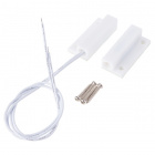
- 1x RHT03 Humidity and Temperature Sensor
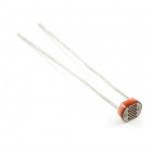
- 1x Mini Photocell
- 1x 330Ω Resistor
- 7x Jumper Wires
Using a Photon by Particle instead or you don't have the kit? No worries! You can still have fun and follow along with this experiment. We suggest using the parts below:
In stock
SEN-10167
The RHT03 (also known by DHT-22) is a low cost humidity and temperature sensor with a single wire digital interface. The sens…
13In stock
SEN-09088
This is a very small light sensor. A photocell changes (also called a [photodetector](http://en.wikipedia.org/wiki/Photodetec…
4In stock
PRT-12795
These are 6" long jumper wires with male connectors on both ends. Use these to jumper from any female header on any board, to…
In stock
COM-11507
1/6 Watt, +/- 5% tolerance PTH resistors. Commonly used in breadboards and perf boards, these 330Ohm resistors make excellent…
1Suggested Reading
- Serial Communication– Serial interfaces allow devices to exchange complex strings of data using just two wires. In this experiment, we’ll use a serial interface between the Photon RedBoard and our computer to check the latest readings from the light and temperature/humidity sensors.
- Serial Terminal Basics– To interact with a serial interface on your computer, you’ll need a serial terminal program. You may already have a serial terminal installed on your computer. If not, check out this tutorial for our recommendations, and a guide to getting started.
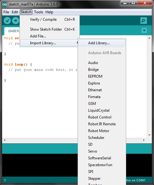
- Including Particle Libraries– Libraries are one of the most powerful tools availabe in the Particle Build IDE. Read through this tutorial to find out how to add a library to your application code.
Hardware Hookup
Hook up your circuit as shown below:
![Environment monitor fritzing diagram]()
The yellow wire running from the photocell to the Photon’s A0 pin carries an analog value relative to the light being sensed. The blue wire, running between the RHT03 sensor and Photon pin D3, is a very precisely-timed digital data interface. The SparkFunRHT03 library simplifies this interface to just a few lines of code.
Both the photocell and the RTH03 need a power supply to be operational. In this circuit, we’re powering both off the Photon’s 3.3V/GND supply.
Photon Code
Copy and paste the code below into a new application – ours is called EnvironmentLoggerSerial:
/////////////////////
// Pin Definitions //
/////////////////////
const int RHT03_DATA_PIN = D3; // RHT03 data pin
const int LIGHT_PIN = A0; // Photocell analog output
const int LED_PIN = D7; // LED to show when the sensor's are being read

///////////////////////////
// RHT03 Object Creation //
///////////////////////////
RHT03 rht; // This creates a RTH03 object, which we'll use to interact with the sensor

unsigned int minimumLight = 65536;
unsigned int maximumLight = 0;
float minimumTempC = 5505;
float maximumTempC = 0;
float minimumTempF = 9941;
float maximumTempF = 0;
float minimumHumidity = 100;
float maximumHumidity = 0;

#define PRINT_RATE 1500 // Time in ms to delay between prints.

void setup()
{
    // Serial.begin() is used to open up a serial interface between the Photon
    // and your computer.
    // The '9600' parameter configures the speed of the interface. This value is
    // called the "baud rate", which is equivalent to bits per second (bps).
    Serial.begin(9600); // Start the serial interface at 9600 bps

    // Using the 'rht' object created in the global section, we'll begin by calling
    // its member function `begin`.
    // The parameter in this function is the DIGITAL PIN we're using to communicate
    // with the sensor.
    rht.begin(RHT03_DATA_PIN);  // Initialize the RHT03 sensor

    // Don't forget to set the pin modes of our analog sensor (INPUT) and the LED (OUTPUT):
    pinMode(LIGHT_PIN, INPUT); // Set the photocell pin as an INPUT.
    pinMode(LED_PIN, OUTPUT); // Set the LED pin as an OUTPUT
    digitalWrite(LED_PIN, LOW); // Initially set the LED pin low -- turn the LED off.
}

void loop()
{
    digitalWrite(LED_PIN, HIGH); // Turn the LED on -- it'll blink whenever the sensor is being read.

    // Use the RHT03 member function `update()` to read new humidity and temperature values from the sensor.
    // There's a chance the reading might fail, so `update()` returns a success indicator. It'll return 1
    // if the update is successful, or a negative number if it fails.
    int update = rht.update();

    if (update == 1) // If the update succeeded, print out the new readings:
    {
        // Use analogRead to get the latest light sensor reading:
        unsigned int light = analogRead(LIGHT_PIN);
        // Do some math to calculate the minimum and maximum light sensor readings we've seen:
        if (light > maximumLight) maximumLight = light;
        if (light < minimumLight) minimumLight = light;

        // The `humidity()` RHT03 member function returns the last successfully read relative
        // humidity value from the RHT03.
        // It'll return a float value -- a percentage of RH between 0-100.
        // ONLY CALL THIS FUNCTION AFTER SUCCESSFULLY RUNNING rht.update()!.
        float humidity = rht.humidity();
        // Do some math to calculate the max/min humidity
        if (humidity > maximumHumidity) maximumHumidity = humidity;
        if (humidity < minimumHumidity) minimumHumidity = humidity;

        // The `tempF()` RHT03 member function returns the last succesfully read
        // farenheit temperature value from the RHT03.
        // It returns a float variable equal to the temperature in Farenheit.
        // ONLY CALL THIS FUNCTION AFTER SUCCESSFULLY RUNNING rht.update()!.
        float tempF = rht.tempF();
        // Do some math to calculate the max/min tempF
        if (tempF > maximumTempF) maximumTempF = tempF;
        if (tempF < minimumTempF) minimumTempF = tempF;

        // `tempC()` works just like `tempF()`, but it returns the temperature value in
        // Celsius.
        // ONLY CALL THIS FUNCTION AFTER SUCCESSFULLY RUNNING rht.update()!.
        float tempC = rht.tempC();
        // Do some math to calculate the max/min tempC
        if (tempC > maximumTempC) maximumTempC = tempC;
        if (tempC < minimumTempC) minimumTempC = tempC;


        // `Serial.print()` is used to send data from the Photon to our computer over the serial interface.
        // The parameter passed to `print()` can be anything from a String, to a constant array of charaters,
        // to a float value, integer, or nearly any other type of variable.
        Serial.print("Light: "); // Print "Light: "
        Serial.print(light); // Print the light reading
        Serial.print(" ("); // Print " ("
        Serial.print(minimumLight); // Print the minimum light reading
        Serial.print('/'); // Print a '/' -- single quotes mean we're only sending one character
        Serial.print(maximumLight); // Print the maximum light reading.
        Serial.println(") (min/max)"); // Finish the line by printing ") (min/max)"
        // The full line will look something like: "Light: 545 (8/791) (min/max)"

        // Print the temperature in °C:
        // Example printout: "Temp: 24.9 °C (23.5/24.5) (min/max)"
        Serial.print("Temp: ");
        Serial.print(tempC, 1); // Printing a float, we can set the precision (number of decimal points) with the second parameter
        Serial.print("");
        // `write()` can be used to write a SINGLE BYTE value over the serial line:
        Serial.write(248); // 248 is the ASCII value for the ° symbol. We're fancy.
        Serial.print("C (");
        Serial.print(minimumTempC, 1);
        Serial.print('/'); // Print a '/'
        Serial.print(maximumTempC, 1);
        Serial.println(") (min/max)");

        // Print the temperature in °F:
        // Example printout: "Temp: 76.1 °F (74.3/76.1) (min/max)"
        Serial.print("Temp: "); // Print "Temp: "
        Serial.print(tempF, 1); // Print the tempF variable -- 1 decimal point
        Serial.print(' ');      // Print a space
        Serial.write(248);      // Print ASCII value 248 (the ° symbol)
        Serial.print("F (");    // Print "F ("
        Serial.print(minimumTempF, 1); // Print minimum temperature -- 1 decimal point
        Serial.print('/');      // Print a '/'
        Serial.print(maximumTempF, 1); // Print maximum temp -- 1 decimal point
        Serial.println(") (min/max)"); // Finsh the line by printing ") (min/max)"

        // Print the relative humidity:
        // Example printout: Humidity: 29.7 % (29.10/41.80) (min/max)
        Serial.print("Humidity: ");
        Serial.print(humidity, 1);
        Serial.print(" %");
        Serial.print(" (");
        Serial.print(minimumHumidity, 1);
        Serial.print("/");
        Serial.print(maximumHumidity, 1);
        Serial.println(") (min/max)");

        Serial.println(); // Print a blank line:
    }
    else // If the update failed, give the sensor time to reset:
    {
        Serial.println("Error reading from the RHT03."); // Print an error message
        Serial.println(); // Print a blank line

        delay(RHT_READ_INTERVAL_MS); // The RHT03 needs about 1s between read attempts
    }
    digitalWrite(LED_PIN, LOW); // Turn the LED off

    delay(PRINT_RATE); // delay for 1s, printing too much will make the output very hard to read.
}
But wait! Don’t try to upload it yet. In fact, if you try to compile, you should get an error, because we need to add the SparkFunRHT03 library.
Click the Libraries icon ![library icon]() on the left. Then click into the search bar and find SparkFunRHT03. Click it to get a description of the library, and options for using it.
on the left. Then click into the search bar and find SparkFunRHT03. Click it to get a description of the library, and options for using it.
![Searching for and including a library]()
Next, click the INCLUDE IN APP button, and select your new application, and verify by selecting ADD TO THIS APP.
![Adding a library to an app]()
Two lines of code should be appended to your application:
language:c
// This #include statement was automatically added by the Particle IDE.
#include "SparkFunRHT03/SparkFunRHT03.h"
That’s the library! Now you can verify and flash.
Including libraries: Unfortunately, there aren't any shortcuts to including libraries in your applications. Simply copying and pasting the #include statement won't actually include the library files in your application. Every time you want to include a library, you'll have to go through the process described above.
What You Should See
After uploading the code, open up a serial terminal to your Photon RedBoard’s port. If you’re on a Windows machine, it should look something like “COMN”. On Mac or Linux, the port should be something like “/dev/tty.usbmodenNNNN”.
Make sure the baud rate is set to 9600. Once the Photon connects (starts pulsing cyan), you should begin to see the light, temperature, and humidity values stream by.
![Example serial monitor output]()
Cover up the light sensor, or shine a flashlight on it. Covering the sensor should make the readings go down – can you get it to 0?
Breathe on the temperature/humidity sensor. Does the temperature value go up? Can you influence the humidity value as well (don’t try too hard – no pouring water on the sensor!)?
Code to Note
Including the SparkFunRHT03 library gives us access to the RHT03 class. To begin using that class, we need to begin by creating an RHT03 object in the global section:
language:c
RHT03 rht; // This creates a RTH03 object, which we'll use to interact with the sensor
rht is the object we’ll use from here on to interact with the sensor. Once that’s set up, we can call rht.begin(<pin>) in the setup() function to initialize the sensor. <pin> should be the Photon digital pin connected to the sensor.
language:c
const int RHT03_DATA_PIN = D3; // RHT03 data pin
...
void setup()
{
    ...
    rht.begin(RHT03_DATA_PIN); // Initialize the RHT03 sensor
    ...
}
Finally, we can read the the temperature and humidity values from the sensor. This is a two-step process: (1) read the sensor to update all values, then (2) using get functions to use the value.
Begin by calling rht.update(). If update() succeeds (indicated by returning a 1), you can call rht.tempF(), rht.tempC(), and rht.humidity() to get the values of interest:
language:c
int update = rht.update(); // Read from the RHT
if (update == 1) // If the update was successful:
{
    float humidity = rht.humidity(); // Read humidity into a variable
    float tempC = rht.tempC(); // Read celsius temperature into a variable
    float tempF = rht.tempF(); // Read farenheit temperature into a variable
    ...
}
Troubleshooting
If your terminal program won’t let you open the serial port – citing an error like: “COM port in use”. Or, if the COM port has disappeared from a selectable list, try following these steps:
- Close the serial terminal program.
- Reset your Photon RedBoard
- Wait for the RedBoard to connect to WiFi
- Open the terminal program back up and try connecting.
If all you see is a stream of “Error reading from the RHT03”, make sure everything is correctly wired up. If you’re still not having any luck with the sensor, consider getting in touch with our tech support team. (It’s normal for the “Error…” output to show up occasionally – the RHT03’s one-wire interface isn’t very robust.)
Part 2: Posting Environment Data to Data.SparkFun.com
As you may have already experienced, using the serial port on a Photon can be very cumbersome. Let’s come up with some way to show off the sensor readings without having to fuss with terminal programs. SparkFun’s Data.SparkFun.com service is a great, FREE, utility for posting, storing, and reading sets of data. It’s powered by Phant, an open-source, Node.js-based tool that can be run on any server or computer.
To get the most out of this example, you should create a data.sparkfun.com data stream of your own. Go to data.sparkfun.com/streams/make, then fill out the form to look something like this:
![Example Phant stream creation]()
Phant Field Names: The most critical box in the Phant stream creation is the "Fields" list. For this example, make sure those five strings are typed exactly as:
humidity, light, station, tempc, and tempf.
After creating the stream, you'll be given a set of keys – long strings of random characters. Don't lose the keys! Either copy them down, or use the "Email me my keys" feature.
New Photon Code
Create a new application, or paste this code over the previous example.
/////////////////////
// Pin Definitions //
/////////////////////
const int RHT03_DATA_PIN = D3; // RHT03 data pin
const int LIGHT_PIN = A0; // Photocell analog output
const int LED_PIN = D7; // LED to show when the sensor's are being read

///////////////////////////
// RHT03 Object Creation //
///////////////////////////
RHT03 rht; // This creates a RTH03 object, which we'll use to interact with the sensor

///////////////////////////////////////////////
// Phant (data.sparkfun.com) Keys and Server //
///////////////////////////////////////////////
// These keys are given to you when you create a new stream:
const char server[] = "data.sparkfun.com"; // Phant destination server
const char publicKey[] = "LQLwdljGJ2TqXgxvAlGv"; // Phant public key
const char privateKey[] = "A1x5rDzw47HWPqyog0lo"; // Phant private key
Phant phant(server, publicKey, privateKey); // Create a Phant object

///////////////////////
// Post Rate Control //
///////////////////////
// data.sparkfun.com limits how often you can post to the service. You are allowed up
// to 100 posts every 15 minutes.
unsigned long lastPost = 0; // lastPost keeps track of the last UNIX time we posted
const unsigned int POST_RATE_S = 60; // This sets the post rate to 60 seconds. Avoid setting it below 10s.

//////////////////////////
// Station Name Globals //
//////////////////////////
String stationName = ""; // String object to keep track of our Photon's name

void setup()
{
    Serial.begin(9600); // Start the serial interface at 9600 bps

    rht.begin(RHT03_DATA_PIN); // Initialize the RHT03 sensor

    pinMode(LIGHT_PIN, INPUT); // Set the photocell pin as an INPUT.
    pinMode(LED_PIN, OUTPUT); // Set the LED pin as an OUTPUT
    digitalWrite(LED_PIN, LOW); // Initially set the LED pin low -- turn the LED off.

    // getDeviceName() -- defined at the bottom of this code -- polls Particle's
    // server to get the name of the Photon running this application.
    getDeviceName(); // Update the stationName String
}

void loop()
{
    // This conditional should only run when the last successful post to Phant
    // was POST_RATE_S (60 seconds) or longer ago.
    // Time.now() returns the current UNIX timestamp (number of seconds since January 1, 1970).
    // It should increase by 1 every second. On a successful POST, we set lastPost equal to Time.now().
    if (lastPost + POST_RATE_S <= Time.now())
    {
        digitalWrite(LED_PIN, HIGH); // Turn the LED on to indicate we're posting
        int update = rht.update(); // Get new values from the RHT03.

        if (update == 1) // If the RHT03 update was successful
        {
            int postResult = 0; // This variable will keep track of whether or not

            //while (postResult <= 0)
            // Phant posts aren't always successful. Our postToPhant() function,
            // defined below, will return 1 if it was successful. Or a negative
            // number if it failed.
            while (postToPhant() <= 0)
            {
                Serial.println("Phant post failed. Trying again."); // Debug statement
                delay(1000); // Delay 1s so we don't flood the server
            }
            // After a successful Phant POST:
            Serial.println("Phant post success!"); // Debug print
            // Set lastPost to current time, so we don't post for another POST_RATE_S seconds:
            lastPost = Time.now();
        }
        else // If the RHT03 update failed:
        {
            delay(RHT_READ_INTERVAL_MS); // Delay to give the sensor time to reset
        }
        digitalWrite(LED_PIN, LOW); // Turn the LED off to indicate we're done posting (/trying to post)
    }
}

// postToPhant() gathers all of our sensor data, bundles it into a Phant post,
// and sends it out to data.sparkfun.com.
// It'll return either 1 on success, or a negative number if the post fails
int postToPhant(void)
{
    Serial.println("Posting to Phant!"); // Debug statement

    // Use phant.add(, ) to add data to each field.
    // Phant requires you to update each and every field before posting,
    // make sure all fields defined in the stream are added here.
    phant.add("humidity", rht.humidity(), 1); // These first three phant adds set a field value to float variable
    phant.add("tempc", rht.tempC(), 1); // The third parameter -- valid for float variables -- sets the number
    phant.add("tempf", rht.tempF(), 1); // of decimal points after the number.
    phant.add("light", analogRead(LIGHT_PIN)); // We can also add an integer
    phant.add("station", stationName); // phant.add(, ) is perfectly valid too!

    // phant.particlePost() performs all of the Phant server connection and HTTP POSTING for you.
    // It'll either return a 1 on success or negative number on fail.
    // It uses the field/value combinations added previously to send Phant its data.
    // MAKE SURE YOU COMMIT A phant.add() FOR EVERY FIELD IN YOUR STREAM BEFORE POSTING!
    return phant.particlePost();
}

///////////////////////////////
// Get Device Name Functions //
///////////////////////////////
// These sets of functions poll Particle's server for the name of our Photon.
// This method is described in Particle's documentation here:
// https://docs.particle.io/reference/firmware/photon/#get-device-name
// Function handlers are used here -- when the Spark.subscribe function
// returns, it will call the nameHandler([topic], [data]) function with our
// Photon's name.
bool validName = false; // Boolean to track if we have a valid name or not

// nameHandler() is a function handler. It's passed to Spark.subscribe() and
// called when that function returns.
// The [data] variable should have the name of our Photon when it's done.
void nameHandler(const char *topic, const char *data)
{
    stationName = String(data);  // Store the name in the stationName global variable
    validName = true; // Set validName to true, so getDeviceName can stop blocking.
}

// getDeviceName manages the spark subscribing and publishing required to get our
// Photon's name. It'll block for up to 30 seconds. On success it'll return a
// positive number. On fail, it'll return 0.
int getDeviceName(void)
{
    Spark.subscribe("spark/", nameHandler);
    Spark.publish("spark/device/name");

    int timeout = 30;
    while ((!validName) && (timeout > 0))
    {
        Serial.println("Waiting for name..." + String(timeout--));
        delay(1000); // Spark.process() is called during delay()
    }

    Serial.println("Station name = " + stationName);

    return timeout;
}
But wait! There’s more! Time to include another library. This time search for the SparkFunPhant library, and include it in your app. If you created a new application, you’ll also need to re-include the SparkFunRHT03 library.
![include the SparkFunPhant library]()
If you created a Phant stream of your own, paste your public and private keys into the publicKey[] and privateKey[] variable values. If you haven’t created your own stream yet, feel free to take ours for a test drive. You can find the stream here. Just please, please don’t abuse it. Don’t set your post rate to faster than 60 seconds, and, once you’ve verified it works, try creating a stream of your own.
What You Should See
After uploading the code, keep an eye on your Photon’s blue, D7 LED. It should illuminate when the device is attempting to send data to data.sparkfun.com, and it’ll turn off when it’s done. To check if your data has been posted to Phant, load up the stream in your web browser (click here if you’re using our test stream). You should see a new row of data at the top, stamped with your Photon’s name, data, and a recent timestamp.
![Example screenshot of data.sparkfun.com]()
Every minute you should see a new row of data appear. Let it run all night! See how cold your room gets. Or find out if anyone’s turning the lights on while you’re sleeping.
Now that your data is on data.sparkfun.com, you can have all sorts of fun with it. For instance, you can load your public key into analog.io– our friends who’ve created a beautiful front-end graphing interface for Phant. Or you can try to create graphs of your own – check out this tutorial using Google Charts.
Code to Note
This application introduces the Phant library, a useful tool to make posting to Phant as painless as can be. To set the Phant library up in your sketch, begin by declaring your keys and the Phant server (data.sparkfun.com):
language:c
const char server[] = "data.sparkfun.com"; // Phant destination server
const char publicKey[] = "LQLwdljGJ2TqXgxvAlGv"; // Phant public key
const char privateKey[] = "A1x5rDzw47HWPqyog0lo"; // Phant private key
Phant phant(server, publicKey, privateKey); // Create a Phant object
The last line there creates a Phant object – phant (lowercase ‘p’) – which we’ll use throughout the rest of the application to send data to Phant. This constructor call gives the Phant object almost everything it needs to know about your Phant stream: the server and the keys.
Posting data to Phant is a two step process: adding field/data combinations, and posting them to the server. To pair your fields with data, call the phant.add(<field>, <value>) function where <field> is a String matching exactly one of the fields in your stream. The <value> part of the Phant post can be almost any data type: in our example we’re adding float’s, ints, and a String.
The entire Phant post takes place in our int postToPhant(void) function:
language:c
int postToPhant(void)
{
    phant.add("humidity", rht.humidity(), 1); // These first three phant.add's pair a field with a float
    phant.add("tempc", rht.tempC(), 1); // The third param - optional for floats - sets the precision
    phant.add("tempf", rht.tempF(), 1); // (the number of decimal points after the number).
    phant.add("light", analogRead(LIGHT_PIN)); // We can also add an integer
    phant.add("station", stationName); // Or add a String is perfectly valid too!

    return phant.particlePost(); // Post our values to the Phant server
}
After you’ve commited an add for every field in your Phant stream, call phant.particlePost() to send them out to the server. This function takes care of the TCP connection, and sends out a valid HTTP POST to the Phant server. When it’s done, it’ll either return a 1 on success, or yield a negative number if it fails.
Troubleshooting
If you’re not seeing any data from your Photon being posted to the stream, it may be failing on the phant.particlePost() function. There are a few reasons the Phant POST might fail:
- No Internet connection – make sure your Photon is pulsing cyan.
- Invalid POST – make sure you have a
phant.add for every field in your stream. Also make sure there aren’t any typos in the field names. - Stream overload – Phant streams on data.sparkfun.com are limited to 300 posts every 15 minutes. Our shared stream is subject to that same limitation. Consider making a stream of your own. It’s free!
We still use serial in this example, but really only for debugging. If you’re still not having any luck, open up your serial port and see what it has to say.
Experiment 7: Automatic Fish Feeder
Introduction
In this experiment, you’ll learn how to control the physical world with digital world using a servo motor. Having the ability to control devices such as motors, relays, actuators, and other moving objects opens up a world of opportunities. For this particular example, you will learn how to control a servo motor with the Photon RedBoard. Once you learn the basics of controlling a servo motor, you’ll automate the task of feeding fish or other small pets by creating an internet-connected auto-feeder.
Parts Needed
You will need the following parts:
- 1x Servo Motor with bag of Motor Mounts and Screws
- 1x Button
- 5x Jumper Wire
Using a Photon by Particle instead or you don't have the kit? No worries! You can still have fun and follow along with this experiment. We suggest using the parts below:
In stock
ROB-09065
Here is a simple, low-cost, high quality servo for all your mechatronic needs. This servo is very similar in size and specifi…
6In stock
COM-10302
These tactile buttons are great for all sorts of projects. This assortment comes with 2 of each of 6 different colors for a t…
In stock
PRT-12795
These are 6" long jumper wires with male connectors on both ends. Use these to jumper from any female header on any board, to…
Along with the parts mentioned above, you will also need a bottle cap or something similar (not included with the Inventor’s Kit) to build your fish feeder. The cap from a water or soda bottle will work best.
![motor mounts]()
The various motor mounts included with your servo motor.
Tools Needed
You will need the screwdriver included in the Photon SIK. If screwing the bottle cap to a servo motor mount proves to be too difficult, you can substitute hot glue or other adhesives to attach the cap the a motor mount.
Suggested Reading
Before continuing on with this experiment, we recommend you be familiar with the concepts in the following tutorials:
- Pulse-width Modulation (PWM) - Pulse-width modulation is the driving force behind how servo motors work and maintain their precision.
- Servo Motor Background - This portion of our Servo Trigger Hookup Guide has a lot of good background information on the theory behind servo motor operation.
- Particle Servo Library - Particle built the servo library into their default functions, so you don’t have to download any extra libraries to use servo motors! Learn about all the functions you can use with Servo.
- Particle Time Library - We will also be using the built-in Particle Time Library to tell our automatic feeder to dispense food at a specific time.
- Particle Cloud Functions - Some of these will be used in the second half of this experiment to expose variables and functions for us to manipulate them over the web.
Hardware Hookup
Hook up your circuit as pictured below:
![Circuit #7]()
Having a hard time seeing the circuit? Click on the Fritzing diagram to see a bigger image.
You can plug the jumper wire ends directly into the servo motor header.
The button will only be used for a brief portion of this experiment. After it has served its use, you can leave out the breadboard entirely. Should you wish to leave your fish feeder intact after you’ve completed all the other experiments, you can hook up the servo to just the Photon RedBoard to make the project more compact.
Photon Code Part 1a
For this experiment, we will need a few different pieces of code. The very first sketch you’ll need to upload will put the servo motor in a known state. When first unpacked, it’s difficult to know what position the servo motor is in, so this sketch moves the motor all the way to the end of its 180° range of motion. Copy and paste the following code into the Particle IDE, and upload it to the Photon RedBoard.
language:c
/*  SparkFun Inventor's Kit for Photon
    Experiment 7 - Part 1a: Servo Motor
    This sketch was written by SparkFun Electronics
    Joel Bartlett <joel@sparkfun.com>
    August 31, 2015
    https://github.com/sparkfun/Inventors_Kit_For_Photon_Experiments

    This application controls a servo with the press of a button.
    Development environment specifics:
    Particle Build environment (https://www.particle.io/build)
    Particle Photon RedBoard
    Released under the MIT License(http://opensource.org/licenses/MIT)
*/
Servo myservo;// create servo object using the built-in Particle Servo Library

int button = D1;    //declare variable for button
int servoPin = D0;  //declare variable for servo
int pos = 0;        //variable to keep track of the servo's position
bool flag = 1;      //variable to keep track of the button presses

// This routine runs only once upon reset
void setup()
{
  Serial.begin(9600);//Start the Serial port @ 9600 baud

  pinMode(button, INPUT_PULLUP);   // sets button pin as input with internal pullup resistor


  myservo.attach(servoPin);  //Initialize the servo attached to pin D0
  myservo.write(180);        //set servo to furthest position
  delay(500);                //delay to give the servo time to move to its position
  myservo.detach();          //detach the servo to prevent it from jittering

}

// This routine loops forever
void loop()
{
    if(digitalRead(button) == LOW) //if a button press has been detected...
    {
      //This is known a s state machine.
      //It will move the servo to the opposite end from where it's set currently
      if(flag == 1)
        pos = 0;
      if(flag == 0)
        pos = 180;

      myservo.attach(servoPin);
      myservo.write(pos);
      delay(500);           //debounce and give servo time to move
      myservo.detach();

      flag = !flag;         //set flag to the opposite of what it's currently set to
      Serial.println(pos);  //prints to the serial port to keep track of the position
    }

}
What You Should See Part 1a
When you first power your Photon RedBoard, give it a few seconds to connect to the web, then you should see the motor move to the 180° position. Once there, it will stay until the button is pressed. Press the button to move it to 0°. Press the button again and it will move back to the first position. The purpose of this code it to give you an idea for the full range of motion for the servo motor and to help you plan out your fish feeder.
![circuit 7]()
Assemble the Fish Feeder
With the above sketch still loaded on your RedBoard, it’s time to build the actual feeding mechanism. Take your bottle cap, and screw (or glue) it onto a motor mount of your choosing. We opted for the single arm in this setup.
![bottle cap motor mount]()
Next, power your RedBoard with the Micro USB cable, if it isn’t already, and open up your favorite Serial Terminal program at 9600 baud. You should now see the position of the servo printed to the screen when the button is pressed.
0
180
0
180
0
180
Hold you servo so that the moving portion is facing you and is on the right-hand side of the motor. Now it’s time to attach the mount to the servo so that the cap dumps your food into the tank. This may take a few tries to get it exactly right.
Move the servo in the 180° position, using the button. Attach the mount by pressing it onto the servo gear until it is snug. We found that positioning the cap at a 45° angle works well as it holds the food and provides a good angle for dumping the food. If you would like to secure your mount with the provided screw, now would be the best time. You may need to screw then unscrew the cap (making holes in it), attach the mount to the servo, screw the mount, then screw the cap back on to the mount.
![hold food]()
With the feeding mechanism attached, press the button again to move into the dumping position (0°). This is your chance to make any adjustments necessary to ensure all of the food gets dumped out.
![dump food]()
If you attached your cap to the motor mount opposite of the image above, you may have to reverse these steps, starting at position 0° and then dumping at 180°.
Photon Code Part 1b
Now, the code will trigger the servo motor at a specific time instead of on a button press. You will need to change the Timezone to your local timezone. You will also need to select an hour and minute at which you’d like your feeder to activate. Copy, paste, and upload the code below.
language:c
/*  SparkFun Inventor's Kit for Photon
    Experiment 7 - Part 1b: Servo Motor with Time
    This sketch was written by SparkFun Electronics
    Joel Bartlett <joel@sparkfun.com>
    August 31, 2015
    https://github.com/sparkfun/Inventors_Kit_For_Photon_Experiments

    This application controls a servo at a specific time.
    Development environment specifics:
    Particle Build environment (https://www.particle.io/build)
    Particle Photon RedBoard
    Released under the MIT License(http://opensource.org/licenses/MIT)
*/
Servo myservo;// create servo object using the built-in Particle Servo Library

int servoPin = D0;  //declare variable for servo

void setup()
{

  myservo.attach(servoPin);  //Initialize the servo attached to pin D0
  myservo.write(180);        //set servo to 180. This position will hold the food
  delay(500);                //delay to give the servo time to move to its position
  myservo.detach();          //detach the servo to prevent it from jittering

  Time.zone(-6);//Set timezone to Mountain Daylight Time (MDT) Spring/Summer
  //Time.zone(-7);//Set timezone to Mountain Standard Time (MST) Fall/Winter
  //Find out your time zone here: http://www.timeanddate.com/time/map/

  Spark.syncTime();//sync with the Particle Cloud's time

}

void loop()
{
  //This if statement checks to see if it is the correct hour and minute of the day to dispense food.
  //The Photon uses 24 hour time so there's no confusion between 1am and 1pm, etc.
  if(Time.hour() == 15 && Time.minute() == 0)  //feed at 3:00pm
  {
    myservo.attach(servoPin);
    myservo.write(0);//set to a zero position. Dumps food
    delay(2000);
    myservo.write(180);//set to a zero position
    delay(500);
    myservo.detach();//detach to keep the servo from jittering

    delay(60000);//wait the rest of the minute out
  }

}
What You Should See Part 1b
Depending on what time you chose in your code, you should see your servo motor turn to the food dumping position at that time and then return to its original position. Before implementing, you should test your code out by entering a time in the not-so-distant future, so you can see the servo move and verify it is working. Once, verified, program the actual feeding time in and integrate it into your fish tank or other habitat.
This code will only get you through one day of feeding. If you will be gone for say three days and want to feed on the second day, you can use the Time.month() and Time.day() functions to check for a specific time on a specific day of the month to feed. Learn more about all of the time functions at Particle.io.
Code to Note
To prepare the Photon RedBoard to control a servo, you must first create a Servo “object” for each servo (here we’ve named it “myservo”), and then “attach” it to a digital pin (here we’re using digital pin D0). This is creating an instance of the Servo class, which is part of the built-in Servo Library.
Servo myservo;
To use the servo after it’s been declared, you must attach it. This tells the Photon to which pin this servo is connected. The detach function relinquishes that pin and stops all signals from being sent to the servo.
myservo.attach(D0);
myservo.detach();
The servo in this kit doesn’t spin all the way around, but they can be commanded to move to a specific position. We use the servo library’s write() command to move a servo to a specified number of degrees(0 to 180). Remember that the servo requires time to move, so give it a short delay() if necessary.
servo.write(180);
delay(500);
The Time library is also built in to the Photon firmware. However, you may have noticed that it does not need to be initialized before it can be used. You can call any of the Time functions at any point in your code. For example, we call Time.zone(-6) without any reference to Time before that.
Troubleshooting
Servo not moving at all - Make sure you have the correct pins in the correct place. Most all servo are color-coded with Red being Power, Black being GND, and White or Yellow being the Signal.
Servo twitching and jittering a lot - If you do not detach your servo after every call, it may twitch and jitter a lot. If this is a problem, add myservo.detach() after every myservo.write() function. Don’t forget to re-attach it before writing it again.
These servos can only withstand a small amount of abuse. If held in a position it doesn’t like for very long, the servo can be permanently damaged. If all the connections are correct, you’re detaching after every servo write, and the servo is still misbehaving, you may have damaged your servo. If your servo arrived in this state, contact our customer service team, and they’ll help you get a replacement.
Part 2: Feed Your Pets from the Internet
Thus far, we’ve only used the web to sync the time on our Photon Redboard. Accurate time is great, but let’s see if we can’t use the Internet more to our advantage. In part 2 of this experiment, you’ll learn how to trigger your auto fish feeder from anywhere in the world as long as it and you have an Internet connection.
New Photon Code
Your circuit will be the same as it was in Part 1, but the code will be slightly different. We’ve added a new line, Spark.function("feed",triggerFeed); and the corresponding function triggerFeed(), explained in the comments below. Copy, paste, and upload the code.
language:c
/*  SparkFun Inventor's Kit for Photon
    Experiment 7 - Part 2: Automatic Fish Feeder
    This sketch was written by SparkFun Electronics
    Joel Bartlett <joel@sparkfun.com>
    August 31, 2015
    https://github.com/sparkfun/Inventors_Kit_For_Photon_Experiments

    This application controls a servo at a specific time and over the web.
    Development environment specifics:
    Particle Build environment (https://www.particle.io/build)
    Particle Photon RedBoard
    Released under the MIT License(http://opensource.org/licenses/MIT)
*/
Serv
Servo myservo;// create servo object using the built-in Particle Servo Library

int servoPin = D0;  //declare variable for servo

int myMinute = 0;  //00
int myHour = 9; //9 am
int myDay = 14;
int myMonth = 8;//August


void setup()
{

  myservo.attach(servoPin);  //Initialize the servo attached to pin D0
  myservo.write(180);        //set servo to 180. This position will hold the food
  delay(500);                //delay to give the servo time to move to its position
  myservo.detach();          //detach the servo to prevent it from jittering

  Time.zone(-6);//Set timezone to Mountain Daylight Time (MDT) Spring/Summer
  //Time.zone(-7);//Set timezone to Mountain Standard Time (MST) Fall/Winter
  //Find out your time zone here: http://www.timeanddate.com/time/map/

  Spark.syncTime();//sync with the Particle Cloud's time

  // We are also going to declare a Spark.function so that we can trigger our feeder from the cloud.
  Spark.function("feed",triggerFeed);
  // When we ask the cloud for the function "feed", it will employ the function triggerFeed() from this app.

}

void loop()
{
  //The Photon uses 24 hour time so there's no confusion between 1am and 1pm, etc.
  //This time we are checking for a specific date and time.
  if(Time.month() == myMonth && Time.day() == myDay) //check the date, if it's not the right day, don't bother with the time.
  {
      if(Time.hour() == myHour && Time.minute() == myMinute) //check the time
      {
        myservo.attach(servoPin);
        myservo.write(0);//set to a zero position. Dumps food
        delay(2000);
        myservo.write(180);//set to a zero position
        delay(500);
        myservo.detach();//detach to keep the servo from jittering

        delay(60000);//wait the rest of the minute out
      }
  }

}


int triggerFeed(String command)
{
/* Spark.functions always take a string as an argument and return an integer.
Since we can pass a string, it means that we can give the program commands on how the function should be used.

In this case, telling the function "feed" will trigger the servo.
Then, the function returns a value to us to let us know what happened.
In this case, it will return 1 if the function was called and -1 if we
received a totally bogus command that didn't do anything.
This does not check for any mechanical failures however. Only code.
*/

    if (command=="feed")
    {
        myservo.attach(servoPin);
        myservo.write(0);//set to a zero position. Dumps food
        delay(2000);
        myservo.write(180);//holding position
        delay(500);
        myservo.detach();
        return 1;
    }
    else
        return -1;
}
What You Should See
When you register a function or variable in the cloud, you’re making a space for it on the internet. There’s a specific address that identifies you and your device. You can send requests, like GET and POST requests, to this URL just like you would with any webpage in a browser.
The code below will give you a webpage from which you can trigger the auto-feeder. Copy and paste the code below into your favorite text editor that can save files as .html.
language:html<!-- Replace your-device-ID-goes-here with your actual device ID
and replace your-access-token-goes-here with your actual access token--><!DOCTYPE><html><body><center><br>
    Feed your pets anywhere you have an Internet connection!<br><br><form name= "input" action="https://api.particle.io/v1/devices/your-device-ID-goes-here/led?access_token=your-access-token-goes-here" method="post"><input type= "submit" name="%" value= "feed" style="height:50px; width:150px"></form></center></body></html>
Edit the code in your text file so that “your-device-ID-goes-here” is your actual device ID, and “your-access-token-goes-here” is your actual access token. These things are accessible through your IDE at build.particle.io. Your device ID can be found in your Devices drawer (the crosshairs) when you click on the device you want to use, and your access token can be found in Settings (the cogwheel).
Open that .html file in a browser. You’ll see a very simple HTML form that allows you to call the triggerFeed functions we exposed earlier.
![Feed Me]()
You’ll get some info back after you submit the page that gives the status of your device and lets you know that it was indeed able to post to the URL. If you want to go back, just click “back” on your browser.
Similarly, you can also call this function by opening a Command Line Terminal and typing
particle call device_name feed feed
Remember to replace device_name with either your device ID or the casual nickname you made for your device when you set it up.
Now, if you need to trigger your autofeeder ahead of schedule for any reason, you can do so with the click of a button on your smartphone or computer.
Code to Note
The Spark.function line is allowing us to “expose” that function to the rest of the Internet. This allows us to trigger the feeder from other mediums such as a webpage or the command line. You can learn more about the Particle Cloud Functions here.
Troubleshooting
- If you cannot get your servo to move via the web or command line interface, you may be calling the wrong device ID. If you have more than one Photon, Photon RedBoard or Core, then it is possible that the device IDs may have been mixed up at some point.
- Another problem could be your access token. If you get an error saying the access token is expired, visit the Particle IDE at build.particle.io and refresh your access token.
Going Further
Need to feed your fish for multiple days? Add a second servo, or grab a continuous rotation servo to create a feeding mechanism that only dispenses a small portion of its food reserves at a time.
You could then try to create a webpage app that allows you to change the feeding time on the fly without having to reprogram your Photon RedBoard.
Experiment 8: Activity Tracker
Introduction
This experiment will get you (or at least your Photon) moving, because we’ll be wiring up a motion-sensing, orientation-finding, 3-axis accelerometer. This experiment serves as an introduction to accelerometers and I2C communication. You’ll also learn about system modes, which allow you to turn WiFi on or off and save loads of battery juice.
![Activity Tracker Photo]()
Parts Needed
- 1x MMA8452Q Accelerometer
- 1x Green Button
- 6x Jumper wires
Using a Photon by Particle instead or you don't have the kit? No worries! You can still have fun and follow along with this experiment. We suggest using the parts below:
In stock
SEN-12756
This breakout board makes it easy to use the tiny MMA8452Q accelerometer in your project. The MMA8452Q is a smart low-power, …
2In stock
COM-10302
These tactile buttons are great for all sorts of projects. This assortment comes with 2 of each of 6 different colors for a t…
In stock
PRT-12795
These are 6" long jumper wires with male connectors on both ends. Use these to jumper from any female header on any board, to…
Suggested Reading
Two big new electronics concepts are introduced in this experiment: Accelerometers and I2C Communication. If you’re interested in learning a lot more about them, check out our tutorials. For now, here’s a quick introduction:
Accelerometers
Accelerometers are movement sensors. They feel acceleration – the rate of change of velocity (how fast something is speeding up or slowing down). They’ve become incredibly common throughout consumer electronics, with a huge range of applications: smartphone’s use them to sense orientation, activity trackers often track steps using an accelerometer, and hard drives use them to sense free-fall (giving them enough time to move and protect delicate parts).
Even if a device isn’t visibly moving, an accelerometer can still give you a lot of information about its orientation. Accelerometers sense the acceleration of gravity, which is a constant, pulling force toward earth. In fact, one of the most common units of acceleration is the g– “gravity” – which is equal to about 9.8 m/s2. An accelerometer sitting flat and motionless, will sense 1g of acceleration towards the ground (usually on the z-axis), and 0g of acceleration in the other two dimensions (x and y).
![MMA8452Q axis orientations]()
There are a huge variety of accelerometers out there. They can monitor anywhere from 1-to-3 axes of acceleration, support various communication interfaces, and host a range of other unique features. In this experiment, we’re using the MMA8452Q– a 3-axis accelerometer with a digital interface. It can be set to sense a maximum of either ±2, 4, or 6 g. It also supports a neat feature called tap, or “pulse” detection.
I2C
The accelerometer we’re using in this experiment communicates over an interface called I2C, short for Inter ICCommunication. I2C is an extremely popular embedded computing communication interface. It’s relatively slow (the Photon and accelerometer communicate at about 400kHz), but only requires two wires for communication. These wires are usually called serial data (SDA) and serial clock (SCL). As you’ll see in the next section, hooking up I2C circuits is as easy as connecting SDA-to-SDA and SCL-to-SCL (don’t forget to power the device too!).
Devices on an I2C bus are called “slaves”, while the lone, controlling component (our Photon RedBoard in this case), is called the “master”. What makes I2C even more powerful is it allows multiple slave devices on a single, two-wire bus. Want to add a pressure sensor to your circuit? Just connect the SDA’s and SCL’s. Each slave device on an I2C bus has a unique address, so they can ignore messages for other devices, and only take action on bytes meant for them.
Hardware Hookup
Here’s the hookup for both parts of this experiment:
![Activity Track fritzing hookup]()
As we mentioned in the I2C section above, an I2C bus is made up of two signals: SDA and SCL. An I2C interface also requires pullup-resistors on those signals, but the breakout board already takes care of that for you.
The button signal is routed to the RedBoard’s D3 pin. We’ll internally pull that pin up, so when the button is inactive it’ll read HIGH. When the button is pressed, D3 will go LOW. We won’t use the button in the first part, but it’ll come in handy later on.
Photon Code
In this experiment, we’ll once again be using the Libraries feature of the Build IDE. To communicate with the accelerometer, we’ll be using the SparkFunMMA8452Q library.
This time, however, we’ll be using another feature of the Libraries tab: examples. Most libraries include at least one example, to help demonstrate their features and usage. To use the SparkFunMMA8452Q library’s example, click USE THIS EXAMPLE (make sure the MMA8452Q-Serial_Example tab is active up top).
![Using a library example]()
The Build IDE will create a new app in your code tab called MMA8452Q-Serial_Example, and it will already have the library included for you.
All you have to do is flash the code!
What You Should See
This part of the experiment is designed to get you familiar with what, exactly, an accelerometer senses. We’ll be reading the acceleration from each of the three axes, then printing those values out to the serial monitor.
Once the Photon begins running the application, open up a serial terminal to view the data. Acceleration sensed on all three axes is displayed at a rate of about 1Hz. There are also some fancy ASCII bar graphs, to visually represent the acceleration values.
![Accelerometer activity printed to serial monitor]()
Sitting flat, you should see about 1 g of acceleration on the z-axis, and nearly 0 g on the x- and y-axes. Carefully – without disturbing any of the wires – tilt your RedBoard and Breadboard around, and monitor the three accelerometer readings. If you flip the board 90°, the z-axis should become 0 g and either x or y will go to 1. Can you tilt the board and get each axis nearly equal?
Code to Note
This example introduces the SparkFunMMA8452Q library. To begin using the library, create an MMA8452Q class object. This’ll often go in the global section of the code:
language:c
// Create an MMA8452Q object, used throughout the rest of the sketch.
MMA8452Q accel; // Default constructor, SA0 pin is HIGH
We’ll use accel from here on to access the accelerometer functions and variables. To initialize the sensor, stick accel.begin() in your setup(). You can give the begin() function two parameters, if you want to configure the sensing range of the accelerometer or the output data rate (ODR).
language:c
// Initialize the accelerometer with begin():
// begin can take two parameters: full-scale range, and output data rate (ODR).
// Full-scale range can be: SCALE_2G, SCALE_4G, or SCALE_8G (2, 4, or 8g)
// ODR can be: ODR_800, ODR_400, ODR_200, ODR_100, ODR_50, ODR_12, ODR_6 or ODR_1
accel.begin(SCALE_2G, ODR_1); // Set up accel with +/-2g range, and slowest (1Hz) ODR
The scale can be set to either ±2, 4, or 8 g, while the output data rate can be set to either 1, 6, 12, 50, 100, 200, 400, or 800 Hz. In our example, the scale is set to its minimum – meaning it’ll have the highest resolution, but be limited to sensing a maximum of ±2 g.
To check if new data is available from the sensor, use the accel.available() function, which will return 1 if there’s data to be read or 0 otherwise.
Once new data is available, call accel.read() to read all acceleration data from the sensor. Then you’ll be able to access any of six class variables: x, y, z– the “raw” 12-bit values from the accelerometer – or cx, cy, and cz, the calculated accelerations in g.
The whole process goes something like this:
language:c
if (accel.available())
{
    accel.read();

    Serial.println("X: " + String(accel.x) + " | " + String(accel.cx, 2) + " g");
    Serial.println("Y: " + String(accel.y) + " | " + String(accel.cy, 2) + " g");
    Serial.println("Z: " + String(accel.z) + " | " + String(accel.cz, 2) + " g");
}
Troubleshooting
Motion and breadboard/jumper circuits aren’t usually a great combination. If your circuit works initially, but mysteriously stops working, a jumper may have been (even briefly) disconnected. Double-check all of your wiring, and restart if anything stops working. Move things around carefully! The base plate is extremely useful for this experiment.
Part 2: Tracking Steps, Publishing Your Acitvity
Accelerometers are commonly used as the motion-sensing foundation of pedometers – step counters. And while the baseplate probably isn’t the most comfortable thing to strap to your belt and walk around with, creating an activity monitor of our own can be a fun exercise. Plus it provides an algorithm you can endlessly try to tweak and perfect.
New Photon Code
Create a new application, and post this code in:
// Pin definitions:
const int BUTTON_PIN = 3; // The Publish button is connected to D3
const int LED_PIN = 7; // The on-board LED is used to indicate status

MMA8452Q accel; // Create an accelerometer object to be used throught the sketch

// stepCount keeps track of the number of steps since the last publish:
unsigned int stepCount = 0;

// To save battery power, we'll put the Photon in SEMI_AUTOMATIC mode.
// So our Photon will not attempt to connect to the Cloud automatically.
// It'll be up to us to issue Particle.connect() commands, when we want
// to connect.
// More on modes here: https://docs.particle.io/reference/firmware/photon/#system-modes
SYSTEM_MODE(SEMI_AUTOMATIC); // Set system mode to SEMI_AUTOMATIC

// We'll use a few booleans to keep track of _if_ we need to publish,
// and if our publish was successful.
bool publishFlag = false;
bool publishSuccess = false;

void setup()
{
    // Begin by turning WiFi off - we're running off batteries, so
    // need to save as much power as possible.
    WiFi.off(); // Turn WiFi off

    // Configure our button and LED pins
    pinMode(LED_PIN, OUTPUT); // LED pin is set as an OUTPUT
    digitalWrite(LED_PIN, HIGH); // Write LOW to set LED off to begin
    pinMode(BUTTON_PIN, INPUT_PULLUP); // Button is configured as input w/ pull-up active

    // Initialize our accelerometer. Set the scale to high-resolution (2g)
    // Set the output data rate to 50Hz.
    accel.begin(SCALE_2G, ODR_50);

    // Next, we'll configure our accelerometer's tap detection interface. This is a
    // very tweak-able function. We can configure the Threshold, time limit, and latency:

    // Pulse threshold: the threshold which is used by the system to detect
    // the start and end of a pulse.
    // Threshold can range from 1-127, with steps of 0.063g/bit.
    //byte threshold = 3; // 3 * 0.063g = 0.189g // This might work better in some cases
    byte threshold = 1; // 2 * 0.063g = 0.063g

    // Pulse time limit: Maximum time interval that can elapse between the start of
    // the acceleration exceeding the threshold, and the end, when acceleration goes
    // below the threshold to be considered a valid pulse.
    byte pulseTimeLimit = 255; // 0.625 * 255 = 159ms (max)

    // Pulse latency: the time interval that starts after first pulse detection, during
    // which all other pulses are ignored. (Debounces the pulses).
    // @50Hz: Each bit adds 10ms (max: 2.56s)
    byte pulseLatency = 64; // 1.25 * 64 = 640ms

    // Use the setupTap function to configure tap detection in our accelerometer:
    accel.setupTap(threshold, threshold, threshold, pulseTimeLimit, pulseLatency);
}

void loop()
{
    // Use the readTap() function to check if a tap was detected:
    byte tap = accel.readTap();
    // readTap will return 1 if there was a tap
    if (tap != 0) // If there was a tap
    {
        stepCount++; // Increment stepCount
        toggleLED(); // Toggle the LED state
    }

    // Next, check if the button was pressed (it's active-low)
    if (digitalRead(BUTTON_PIN) == LOW)
    {   // If the button was pressed
        if (publishFlag == false) // and if we aren't publishing:
        {
            // We're in SEMI_AUTOMATIC system mode, so it's up to us
            // to connecto to the Particle cloud.
            // We've also turned WiFi off, so we'll have to connect to that too.
            WiFi.on();  // Turn WiFi on
            WiFi.connect(); // Connect to our WiFi network
            Particle.connect(); // Connect to the Particle cloud

            digitalWrite(LED_PIN, LOW); // Turn the LED off
            publishFlag = true; // Indicate that we are publishing
        }
    }

    // It takes a few seconds to connect to the Particle cloud.
    // We'll use Particle.connected() to check if we've connected
    // If we're connected, and need to publish:
    if (publishFlag && Particle.connected())
    {
        // Each step usually creates about 2 taps (arm or leg going forward then backward)
        stepCount /= 2; // Dividing by 2 usually makes for a much more accurate step count:

        // Call Particle.publish to push our step count to the web:
        publishSuccess = Particle.publish("Steps", String(stepCount / 2));

        // If the publish was successful
        if (publishSuccess)
        {
            publishFlag = false; // clear the publishFlag
            stepCount = 0; // and reset the step count
        }
        // Allow the Photon some time to Publish before disconnecting
        delay(5000); // Delay 5 seconds
    }

    // If we've successfully published, and are still connected to the Partice cloud
    if (publishSuccess && Particle.connected())
    {
        WiFi.off(); // Turn off WiFi
        publishSuccess = false; // Clear our publishSuccess flag
    }
}

// toggleLED() simply toggles the LED each time it's called. From on to off, or off to on.
void toggleLED()
{
    static bool ledState = true;
    if (ledState)
    {
        digitalWrite(LED_PIN, HIGH);
        ledState = false;
    }
    else
    {
        digitalWrite(LED_PIN, LOW);
        ledState = true;
    }
}
As with the previous part’s code, you’ll need to include the SparkFunMMA8452Q library in this application.
What You Should See
After flashing code to your Photon, remove the USB cable, and plug in a 9V battery via the included 9V-to-Barrel Jack adapter.
Before walking away, open up the Particle Dashboard, and click over to the “Logs” tab. It should be empty for now.
When your Photon boots up, it’ll immediately begin running the application code. You’ll also notice the RGB LED is blinking white-ish, which indicates the device is not connected to the Particle cloud.
Strap your circuit to your belt, or just hold it in your hand, and take about 50 steps. When you want to publish your step count, hit the green button. Your Photon will stop tracking steps while it connects to WiFi and the Particle Cloud, then posts the step count. When the activity publishes, you should see a new row-entry on the dashboard.
![Particle Dashboard]()
After successfully publishing, the Photon RedBoard shuts of WiFi and goes back into step counting mode.
There are a variety of ways to check for published events from your Photon. In raw URL form, you can subscribe to events by directing your browser to a URL like:
https://api.particle.io/v1/devices/DEVICE_ID/events?access_token=ACCESS_TOKEN
Replacing DEVICE_ID with your Photon RedBoard’s device ID (found under the “Devices” tab), and swapping in your access token (in the “Settings” tab) for ACCESS_TOKEN. You’ll initially get a mostly blank page, but as your Photon connects and publishes, new events will pop up:
![HTTP event subscription]()
Those events include your Photon RedBoard connecting, disconnecting, and publishing an event called “Steps”. If you listen for those events, and do some JSON-parsing, you can build a simple HTML/Javascript page to list your step counts.
As a simple example, copy and paste this code into a text editor. Grab your device ID and access token and plug them into the deviceID and accessToken variables (between the quotes).
language:html<!DOCTYPE HTML><html><body><p><p><h3><span id="subscription"></span></h3></p><p>Status: <span id="connectStatus">Nothing yet</span></p><p>Step Counts: <span id="stepList"></span></p><script type="text/javascript">
    function connect()
    {
        var deviceID = ""; // Photon RedBoard device ID
        var accessToken = ""; // Particle account access token

        // Subscribe to any events published by our Photon Device ID:
        var eventSource = new EventSource(
        "https://api.particle.io/v1/devices/" + deviceID + "/events/?access_token=" + accessToken);

        // When the connection opens, it'll publish an "open" event:
        eventSource.addEventListener('open', function(event)
        {
            var subSpan = document.getElementById("subscription");
            subSpan.innerHTML = "Connected. Listening for steps!";
        }, false);

        // If our eventSource fails to connect, it'll give an error:
        eventSource.addEventListener('error', function(event)
        {
            var subSpan = document.getElementById("subscription");
            subSpan.innerHTML = "Not connected :(";
        }, false);

        // Online/offline messages are published as "spark/status" events:
        eventSource.addEventListener('spark/status', function(event)
        {
            var jData = JSON.parse(event.data); // Parse the JSON data
            // Find the "data" key. It'll either be "offline" or "online":
            var statusData = jData.data;
            // Find the "publihsed_at" key, it'll be a timestamp:
            var statusTime = jData.published_at;

            // Put the data we've parsed into the "connectStatus" span:
            var statusSpan = document.getElementById("connectStatus");
            statusSpan.innerHTML = statusData + " (" + statusTime + ")";
        }, false);

        eventSource.addEventListener('Steps', function(event)
        {
            var jData = JSON.parse(event.data); // Parse the JSON data

            var stepCount = jData.data; // Find the "data" key, it'll be the step count
            var stepTime = jData.published_at; // Also get the timestamp from "published_at" key

            // Put the data we've parsed into the "stepList" span:
            var stepsSpan = document.getElementById("stepList");
            stepsSpan.innerHTML = stepsSpan.innerHTML + stepCount + " (" + stepTime + ")" + "<br>";

        }, false);
    }
    window.onload = connect; // Run the connect() function when the page loads
    </script></body></html>
Then open your HTML file with your favorite web browser. And publish some step counts. Eventually your HTML page will begin to fill out:
![An HTML page to listen for published steps]()
System Modes, and Controlling WiFi
Photon System Modes are used to control the Photon RedBoard’s connection to WiFi and the Particle cloud. In this experiment we turn off WiFi whenever it’s not necessary – you don’t need an Internet connection to track steps!
The Photon's WiFi component is a relatively huge power-consumer (pulling, on average, about 50-60mA). That may not be a big deal when it's powered over USB, but when we're operating on battery power, every miliwatt (mW) saved means less money going toward replacing batteries. Turning off WiFi can more than double the amount of time our project can run off a battery.
Control of the Photon’s WiFi connection begins before setup(), by calling the SYSTEM_MODE macro:
language:c
// SEMI_AUTOMATIC mode starts the application up without WiFi, not connected to the
// Particle cloud. Call Particle.connect() manually to connect to WiFi, after that
// Particle.process()'s will be handled for us.
SYSTEM_MODE(SEMI_AUTOMATIC); // Semi-automatic WiFi/cloud mode
SYSTEM_MODE can either be AUTOMATIC, SEMI_AUTOMATIC or MANUAL. AUTOMATIC is the default state, which you should be extremely familiar with by now. The Photon boots up and immediately tries to connect to WiFi and the Cloud before running the sketch.
In SEMI_AUTOMATIC mode, our Photon jumps straight into our application code. It won’t try to connect to the cloud until we call Particle.connect(). While the device is connected, its connection with the cloud is automatically administered, and Particle.disconnect() can be called to disconnect from the Particle cloud.
In addition to the SYSTEM_MODE control, the application also manages our WiFi connection with WiFi.on(), WiFi.connect(), and WiFi.off(). For example, after the button has been pressed, we tell the Photon RedBoard to connect to WiFi and the Particle cloud like this:
language:c
WiFi.on(); // Turn the WiFi module on
WiFi.connect(); // Connect to the pre-set WiFi SSID
Particle.connect(); // Connect to the Particle Cloud
And once we’ve successfully published, WiFi.off() is called to shut the WiFi system down.
It takes some extra planning to use anything but AUTOMATIC mode, but it can result in a big payoff.
Sensing Steps
Before we can publish any step count, we have to sense them. To be honest, pedometer algorithm’s are tough. The MMA8452Q has a neat feature called pulse detection, that we can pigeonhole into our step-counting application. We can set the accelerometer to continuously monitor all three axes for short pulses of motion on any of the three axes, which will be assumed as a step.
To setup pulse or “tap” detection on the MMA8452Q, use the setupTap() function – giving it threshold and timing parameters. We’ll set the threshold to be very low – so just about any movement will create a tap – and set the time window between pulses to about 500ms.
language:c
// Threshold can range from 1-127, with steps of 0.063g/bit.
byte threshold = 1; // 2 * 0.063g = 0.063g (minimum threshold

// Pulse time limit: Maximum time interval that can elapse between the start of
// the acceleration exceeding the threshold, and the end, when acceleration goes
// below the threshold to be considered a valid pulse.
byte pulseTimeLimit = 255; // 0.625 * 255 = 159ms (max)

// Pulse latency: the time interval that starts after first pulse detection, during
// which all other pulses are ignored. (Debounces the pulses).
// @50Hz: Each bit adds 10ms (max: 2.56s)
byte pulseLatency = 64; // 1.25 * 64 = 640ms
accel.setupTap(threshold, threshold, threshold, pulseTimeLimit, pulseLatency);
How fast do you walk? Everyone has a different gait, so you may have to tweak these values to get a more accurate step count.
Code to Note
Particle Publish will be our tool for sharing our step activity with the world. Publish can be used to post named event data to the Particle Cloud, where it can be grabbed by another application and displayed or used otherwise.
In this example, we’re publishing our step data under the “Steps” event name, and including the step count under that data. Just a few lines of code are required to publish, and verify a successful publish:
language:c
// Call Particle.publish to push our step count to the web:
publishSuccess = Particle.publish("Steps", String(stepCount / 2));

// If the publish was successful
if (publishSuccess)
{
    publishFlag = false; // clear the publishFlag
    stepCount = 0; // and reset the step count
}
The Particle Dashboard is an easy tool for viewing your device’s published data. In leiu of anything more complex, we can use that interface to easily monitor the number of steps our RedBoard has taken.
Beyond the Dashboard, once you’ve published your data to the Cloud, there should be no shortage of actions you can take with it. You can set up a webhook, to monitor the event and post its data. Or even configure a second Photon to Subscribe to the event, to track multiple Photon activity monitors.
Troubleshooting
Saving power is great, but it can lead to some headaches if you need to upload new code to the Photon. If your Photon’s WiFi is off, or if it’s not connected to the cloud, you won’t be able to flash new code to it. Thankfully, there’s Safe Mode. By booting your Photon into safe mode, it skips running your application and instead connects to the Particle Cloud and waits for a new program.
To boot into safe mode, hold down both the RESET and MODE buttons. Then release RESET to turn the Photon on. When the RGB LED begins blinking pink-ish, release MODE. Your Photon will run through its WiFi/Cloud connection process, then breathe pink. Once it’s breathing pink, you’ll be able to successfully flash new code to it.
Going Further
There are plenty of projects that can combine motion sensing and the Internet. How about putting this same circuit on top of your dryer– have it alert you when the shaking stops, so you can go grab your clothes before they wrinkle (escaping any potential scolding from your significant other)!
Experiment 9: Home Security
Introduction
Home security and automation are hot topics for IoT (Internet of Things). In this experiment, you will learn how to detect if someone is entering a room. There are a lot of different ways you can detect motion in your home. For this kit, we included both the PIR motion sensor and the Magnetic Door Switch Set. PIR motion sensor is great for when you need to detect motion farther away within a room. The Magnetic Door Switch Set is a small reed switch assembly specifically designed to alert you when doors, drawers, or any other aperture opens.
We are going to show you two different circuits. One for the PIR motion sensor and the other for the Magnetic Door Switch. The code and hook-up for both circuits are fairly similar, so we decided to put both of them in one big experiment about home security.
If you want to have an alarm, add piezo speaker to the experiments below. For the sake of your ears, we are using the onboard LED (D7) to show when motion is detected instead of the piezo speaker. You will thank us later.
Alright, time to learn how to catch anyone who steals cookies out of your cookie jar!
PIR Motion Sensor
PIR (passive infrared) sensor is a simple to use motion sensor. We are going to power it up and wait 1-2 seconds for the sensor to get a snapshot of the still room. If anything moves after that period, the ‘alarm’ pin will go low.
Parts Needed
You will need the following parts:
- Photon RedBoard, Breadboard, and Base Plate
- 1x PIR Sensor
- 1x JST Right Angle Connector - Through-Hole 3-Pin
- 3x Jumper Wires
Using a Photon by Particle instead or you don't have the kit? No worries! You can still have fun and follow along with this experiment. We suggest using the parts below:
In stock
SEN-13285
This is a simple to use motion sensor. Power it up and wait 1-2 seconds for the sensor to get a snapshot of the still room. I…
2In stock
PRT-12795
These are 6" long jumper wires with male connectors on both ends. Use these to jumper from any female header on any board, to…
In stock
PRT-09750
This is a 3-pin, through-hole PH series JST connector. The pins are spaced by 2mm.
We really like the solid locking feeling…
Suggested Reading
- Pull-up Resistors - Pull-up resistors are very common when using microcontrollers (MCUs) or any digital logic device. This tutorial will explain when and where to use pull-up resistors, then we will do a simple calculation to show why pull-ups are important.
PIR Motion Sensor Hardware Hookup
To make it easier to breadboard the PIR motion sensor, you will want to add the JST Right Angle Connector - Through-Hole 3-Pin.
![Connecting the JST connector to the PIR Sensor cable]()
Make sure to push the PIR motion sensor’s JST female connector into the JST right angle connector as much as you can. After you do that, now you are ready to breadboard.
![PIR RedBoard Home Security]()
Having a hard time seeing the circuit? Click on the Fritzing diagram to see a bigger image.
Photon Code
language:c
/*  SparkFun Inventor's Kit for Photon
    Experiment 9 - Part 1: Home Security with PIR
    This sketch was written by SparkFun Electronics
    August 31, 2015
    https://github.com/sparkfun/Inventors_Kit_For_Photon_Experiments

    This application uses a PIR motion sensor to detect motion
    Development environment specifics:
    Particle Build environment (https://www.particle.io/build)
    Particle Photon RedBoard
    Released under the MIT License (http://opensource.org/licenses/MIT)
*/

int pirPin = D0; // PIR is connected to D3
int led = D7;    // Onboard LED is D7

void setup()
{
  pinMode(pirPin, INPUT_PULLUP); // Initialize D3 pin as input with an internal pull-up resistor
  pinMode(led, OUTPUT);          // Initialize D7 pin as output
}


void loop()
{
  int pirValState;

  pirValState = digitalRead(pirPin);

  if(pirValState == LOW){      // Was motion detected
    digitalWrite(led, HIGH);   // Turn ON the LED
    delay(2000); // Wait 1-2 seconds for the sensor to get a snapshot of the still room
  }
  else
  {
    digitalWrite(led, LOW);  // Turn the LED off
  }

}
What You Should See
When you wave your hand over the PIR motion sensor, the onboard LED (D7) will light up!
Get creative and add a piezo speaker! You can be far away and hear an alarm go off if someone sneaks in! Maybe useful in a zombie apocalypse to give you enough time to escape. Might attract attention of more zombies too. We haven’t decided yet.
![Piezo speaker and PIR motion sensor hookup Photon RedBoard]()
Code to Note
if(pirValState == LOW){ // Was motion detected
When motion is detected, the ‘alarm’ pin will go low.
Troubleshooting
- If nothing happens, double check your connections. It is easy to swap the jumper wires for the PIR motion sensor. The white wire on the PIR motion sensor is connected to the GND. Lots of time when we see a black wire, we think it automatically is GND. It is always important to check the datasheets and hook-up guides. Wire colors varies from different manufacturers and don’t always follow the same standards.
Magnetic Door Switch Set
These types of switches are primarily used in home security systems. One half of the assembly set on a window or door frame and the other attached to the window or door itself. When the switch set is separated from each other the contact is broken and triggers an alarm. You can use this set in non-security applications too. For example to trigger a music box to play a song when you open the box.
When each piece comes within 20mm of each other they complete the circuit with the internal reed switches.
Parts Needed
You will need the following parts:
- Photon RedBoard, Breadboard, and Base Plate
- 1x Magnetic Door Switch Set
- 2x Jumper Wires
Using a Photon by Particle instead or you don't have the kit? No worries! You can still have fun and follow along with this experiment. We suggest using the parts below:
In stock
PRT-12795
These are 6" long jumper wires with male connectors on both ends. Use these to jumper from any female header on any board, to…
In stock
COM-13247
This is the Magnetic Door Switch Set, a small reed switch assembly specifically designed to alert you when doors, drawers, or…
Suggested Reading
- Pull-up Resistors - Pull-up resistors are very common when using microcontrollers (MCUs) or any digital logic device. This tutorial will explain when and where to use pull-up resistors, then we will do a simple calculation to show why pull-ups are important.
- Switch Basics - Reed switches open or close when exposed to the presence of a magnetic field. Learn more about different types of switches with this tutorial.
Magnetic Door Switch Set Hookup
You have two parts of the Magnetic Door Switch Set. Set off to the side, the part that does not have the wires. Connect the part that has the wires coming out to the breadboard. It doesn’t matter which wire goes to GND pin or a digital pin. They are interchangeable.
![Home Secruity Reed Switch Photon RedBoard]()
Having a hard time seeing the circuit? Click on the Fritzing diagram to see a bigger image.
Photon Code
language:c
/*  SparkFun Inventor's Kit for Photon
    Experiment 9 - Part 1: Home Security with Magnetic Door Switch Set
    This sketch was written by SparkFun Electronics
    August 31, 2015
    https://github.com/sparkfun/Inventors_Kit_For_Photon_Experiments

    This application uses a Magnetic Door Switch Set to detect motion
    Development environment specifics:
    Particle Build environment (https://www.particle.io/build)
    Particle Photon RedBoard
    Released under the MIT License (http://opensource.org/licenses/MIT)
*/

int magnetPin = D3; // magnet part is connected to D3
int led = D7;     // Onboard LED is D7

void setup()
{
  pinMode(magnetPin, INPUT_PULLUP); // Initialize D3 pin as input with an internal pull-up resistor
  pinMode(led, OUTPUT);           // Initialize D7 pin as output
}


void loop()
{
  int magnetValState;

  magnetValState = digitalRead(magnetPin);

  if(magnetValState == HIGH){      // Was motion detected
    digitalWrite(led, HIGH);     // Turn ON the LED
  }
  else
  {
    digitalWrite(led, LOW);  // Turn the LED off
  }

}
What You Should See
Move the two parts next to each other. The onboard LED (D7) will be off. If you move the parts away from each other the onboard LED will come on.
You can add a piezo speaker as an alarm or play fun songs when something opens.
![Reed Switch with Photon RedBoard hookup]()
Code to Note
if(magnetValState == HIGH){ // Was motion detected
This code is almost identical to the PIR motion sensor. Instead of LOW, we switched it HIGH, so the onboard LED (D7) will only come on when both parts are away from each other.
Troubleshooting
- If your code refuses to flash, try putting your Photon RedBoard into safe mode. Then, hit Flash.
Experiment 10: Pong!
Introduction
In this experiment, we’ll use the OLED Breakout, potentiometer, and a photo resistor to make a game of Pong, where the paddles are controlled by the analog values of the two sensors.
![alt text]()
Parts Needed
You will need the following parts (besides your Photon RedBoard and Breadboard, of course):
- 1x OLED Breakout Board
- 1x Potentiometer
- 1x Photoresistor
- 1x 330 Ohm Resistor
- 15x Jumper Wires
Using a Photon by Particle instead or you don't have the kit? No worries! You can still have fun and follow along with this experiment. We suggest using the parts below:
In stock
SEN-09088
This is a very small light sensor. A photocell changes (also called a [photodetector](http://en.wikipedia.org/wiki/Photodetec…
4Out of stock
LCD-13003
The SparkFun Micro OLED Breakout Board breaks out a small monochrome, blue-on-black OLED. It’s "micro", but it still packs …
13In stock
COM-09806
There are lots of trimpots out there. Some are very large, some so small they require a screwdriver. Here at SparkFun, we jus…
4In stock
COM-08377
1/6th Watt, +/- 5% tolerance PTH resistors. Commonly used in breadboards and perf boards, these 330Ohm resistors make excelle…
Suggested Reading
Hardware Hookup
We’ll be connecting three devices to our Photon RedBoard - the OLED breakout, a trim potentiometer, and a photocell. These last two are analog sensors that are going to act as the paddle controllers for each player, while the OLED screen displays the ball, the paddles, and the score.
![alt text]()
Having a hard time seeing the circuit? Click on the Fritzing diagram to see a bigger image.
The photocell is hooked up to pin A0 and GND though a 330 (NOT 10K) Ohm resistor from one pin, while the other pin is connected to +3.3V. The potentiometer’s middle pin goes to pin A1, while the side pins are connected to GND and 3.3V.
Here’s a handy table for the OLED Breakout connections:
| Photon RedBoard Pin | OLED Breakout Pin | | | A2 | CS | |
| A3 | SCK | |
| A5 | SDI | |
| D5 | D/C | |
| D6 | RST | |
| 3V3 | 3.3V | |
| GND | GND | |
The table and Fritzing image are much more helpful, but if you wanted to see inside the box, here’s a shot of the breadboarded circuit:
![alt text]()
Photon Code
Pong is a great programming exercise for getting used to a new language or environment. There are tons of great pong tutorials out there, so we’re not going to focus too much on the general code beyond the parts that interact with the hardware.
The first thing we need to do after creating a new app is to add the SparkFun OLED library to our sketch. This let’s us draw and write all manner of things to the OLED screen quite easily. First, click on the bookmark icon in the sidebar (it’s the fourth one up from the bottom). Under ‘Community Libraries’, there should be a search box - type in OLED, and you should see the ‘SparkFunMicroOLED’ Library pop up, like so:
![alt text]()
Click on the library name, and then on the big blue button that says “Include in App”. That should cause a line like #include "SparkFunMicroOLED/SparkFunMicroOLED.h" to appear near the top of your sketch. Voila!
Now that you’ve imported the library, you can copy and paste the rest of the code beneath:
language:c
/*  SparkFun Inventor's Kit for Photon
    Experiment 10 - Part 1
    This sketch was written by SparkFun Electronics
    Ben Leduc-Mills
    August 31, 2015
    https://github.com/sparkfun

    This is an example sketch for an analog sensor Pong game.

    Development environment specifics:
    Particle Build environment (https://www.particle.io/build)
    Particle Photon RedBoard
    Released under the MIT License(http://opensource.org/licenses/MIT)
*/
//////////////////////////
// MicroOLED Definition //
//////////////////////////

#define PIN_RESET D6  // Connect RST to pin 6
#define PIN_DC    D5  // Connect DC to pin 5 (required for SPI)
#define PIN_CS    A2 // Connect CS to pin A2 (required for SPI)
//MicroOLED oled(MODE_SPI, PIN_RESET, PIN_DC, PIN_CS);
MicroOLED oled(MODE_SPI, PIN_RESET, PIN_DC, PIN_CS);

//#define SINGLE_PLAYER

const int player1Pin = A1;
#ifndef SINGLE_PLAYER
const int player2Pin = A0;
#endif

/*** Sensor Calibration ****/

int sensor1Calibration = LCDHEIGHT; //photocell w/330
int sensor2Calibration = LCDHEIGHT; //potentiometer

//potentiometer
int sensor1Min = 0;
int sensor1Max = 4096;
//photocell
int sensor2Min = 100;
int sensor2Max = 1000;


/*** Game Settings ***/
const int renderDelay = 16;
const int startDelay = 2000;
const int gameOverDelay = 3000;
const int scoreToWin = 10;

int player1Score = 0;
int player2Score = 0;

const float paddleWidth = LCDWIDTH / 16.0;
const float paddleHeight = LCDHEIGHT / 3.0;
const float halfPaddleWidth = paddleWidth / 2.0;
const float halfPaddleHeight = paddleHeight / 2.0;

float player1PosX = 1.0 + halfPaddleWidth;
float player1PosY = 0.0;
float player2PosX = LCDWIDTH - 1.0 - halfPaddleWidth;
float player2PosY = 0.0;

// This is only used in SINGLE_PLAYER mode:
#ifdef SINGLE_PLAYER
float enemyVelY = 0.5;
#endif


/*** Ball Physics ***/
const float ballRadius = 2.0;
const float ballSpeedX = 1.0;
float ballPosX = LCDWIDTH / 2.0;
float ballPosY = LCDHEIGHT / 2.0;
float ballVelX = -1.0 * ballSpeedX;
float ballVelY = 0;

void setup()
{
// in our setup, we call a few custom functions to get everything ready
  initializeGraphics();
  initializeInput();
  displayGameStart();
  Serial.begin(9600);
}


void loop()
{
  updateGame(); //custom function to advance the game logic
  renderGame(); //custom function to dislay the current game state on the OLED screen
  // print out sensor values via serial so we can calibrate
  Serial.print(analogRead(A0));
  Serial.print("<-A0 | A1-> ");
  Serial.println(analogRead(A1));

  //winning conditions
  if (player1Score >= scoreToWin)
  {
    gameOver(true);
  }
  else if (player2Score >= scoreToWin)
  {
    gameOver(false);
  }
}

//start the OLED and set the font type we want
void initializeGraphics()
{
  oled.begin();
  oled.setFontType(1);
}

//get either 1 or 2 pins ready for analog input
void initializeInput()
{
  pinMode(player1Pin, INPUT);
  #ifndef SINGLE_PLAYER
  pinMode(player2Pin, INPUT);
  #endif
}

//display the start screen
void displayGameStart()
{
  oled.clear(PAGE);
  renderString(20, 10, "Get");
  renderString(10, 30, "Ready!");
  oled.display();
  delay(startDelay);
}

//update the positions of the player paddles and the ball
void updateGame()
{
  updatePlayer1();
  updatePlayer2();
  updateBall();
}

//reset the score, ball position, and paddle positions for a new game
void resetGame()
{
  player2Score = 0;
  player1Score = 0;
  player2PosY = 0.0;
  ballPosX = LCDWIDTH / 2.0;
  ballPosY = LCDHEIGHT / 2.0;
  ballVelX = -1.0 * ballSpeedX;
  ballVelY = 0.0;
}


float clampPaddlePosY(float paddlePosY)
{
  float newPaddlePosY = paddlePosY;

  if (paddlePosY - halfPaddleHeight < 0)
  {
    newPaddlePosY = halfPaddleHeight;
  }
  else if (paddlePosY + halfPaddleHeight > LCDHEIGHT)
  {
    newPaddlePosY = LCDHEIGHT - halfPaddleHeight;
  }

  return newPaddlePosY;
}

void updatePlayer1()
{
  int potVal = analogRead(player1Pin);
  player1PosY = map(potVal, sensor1Min, sensor1Max, 0, sensor1Calibration);
}

void updatePlayer2()
{
  // If it's a single player game, update the AI's position
#ifdef SINGLE_PLAYER
  // Follow the ball at a set speed
  if (player2PosY < ballPosY)
  {
    player2PosY += enemyVelY;
  }
  else if (player2PosY > ballPosY)
  {
    player2PosY -= enemyVelY;
  }

  player2PosY = clampPaddlePosY(player2PosY);
#else  // Else if this is multiplayer, get player 2's position
  int lightVal = analogRead(player2Pin);
  player2PosY = map(lightVal, sensor2Min, sensor2Max, 0, sensor2Calibration);
  //Serial.println(player2PosY);
#endif
}

void updateBall()
{
  ballPosY += ballVelY;
  ballPosX += ballVelX;

  // Top and bottom wall collisions
  if (ballPosY < ballRadius)
  {
    ballPosY = ballRadius;
    ballVelY *= -1.0;
  }
  else if (ballPosY > LCDHEIGHT - ballRadius)
  {
    ballPosY = LCDHEIGHT - ballRadius;
    ballVelY *= -1.0;
  }

  // Left and right wall collisions
  if (ballPosX < ballRadius)
  {
    ballPosX = ballRadius;
    ballVelX = ballSpeedX;
    player2Score++;
  }
  else if (ballPosX > LCDWIDTH - ballRadius)
  {
    ballPosX = LCDWIDTH - ballRadius;
    ballVelX *= -1.0 * ballSpeedX;
    player1Score++;
  }

  // Paddle collisions
  if (ballPosX < player1PosX + ballRadius + halfPaddleWidth)
  {
    if (ballPosY > player1PosY - halfPaddleHeight - ballRadius &&
        ballPosY < player1PosY + halfPaddleHeight + ballRadius)
    {
      ballVelX = ballSpeedX;
      ballVelY = 2.0 * (ballPosY - player1PosY) / halfPaddleHeight;
    }
  }
  else if (ballPosX > player2PosX - ballRadius - halfPaddleWidth)
  {
    if (ballPosY > player2PosY - halfPaddleHeight - ballRadius &&
        ballPosY < player2PosY + halfPaddleHeight + ballRadius)
    {
      ballVelX = -1.0 * ballSpeedX;
      ballVelY = 2.0 * (ballPosY - player2PosY) / halfPaddleHeight;
    }
  }
}


void renderGame()
{
  oled.clear(PAGE);

  renderScores(player1Score, player2Score);
  renderPaddle(player1PosX, player1PosY);
  renderPaddle(player2PosX, player2PosY);
  renderBall(ballPosX, ballPosY);

  oled.display();
  delay(renderDelay);
}

void renderString(int x, int y, String string)
{
  oled.setCursor(x, y);
  oled.print(string);
}

void renderPaddle(int x, int y)
{
  oled.rect(
    x - halfPaddleWidth,
    y - halfPaddleHeight,
    paddleWidth,
    paddleHeight);
}

void renderBall(int x, int y)
{
  oled.circle(x, y, 2);
}

void renderScores(int firstScore, int secondScore)
{
  renderString(10, 0, String(firstScore));
  renderString(LCDWIDTH - 14, 0, String(secondScore));
}

void gameOver(bool didWin)
{
  if (didWin)
  {
#ifdef SINGLE_PLAYER
    renderString(20, 10, "You");
    renderString(20, 30, "Win!");
#else
    renderString(0, 10, "Playr 1");
    renderString(15, 30, "Wins");
#endif
  }
  else
  {
#ifdef SINGLE_PLAYER
    renderString(20, 10, "You");
    renderString(15, 30, "Lose!");
#else
    renderString(0, 10, "Playr 2");
    renderString(15, 30, "Wins");
#endif
  }

  oled.display();
  delay(gameOverDelay);

  // Get ready to start the game again.
  resetGame();
  displayGameStart();
}
What You Should See
After successfully flashing the code onto your Photon RedBoard, you should see the words ‘Get Ready!’ on the OLED screen, followed soon after by the familiar Pong game screen. If you’ve calibrated your sensors well, you should be able to move each paddle up and down to defend your side. After a player wins, the game should start all over again.
If you turn the potentiometer or place your hand over the photocell, the paddles should move up and down, allowing you to play a game of Pong:
![alt text]()
Code to Note
Whew! That’s a lot of code to digest all at once. Let’s look at a few of the key sections that make this work.
Defining our pin assignments and declaring our OLED object happens right at the top:
language:c
#define PIN_RESET D6  // Connect RST to pin 6
#define PIN_DC    D5  // Connect DC to pin 5 (required for SPI)
#define PIN_CS    A2 // Connect CS to pin A2 (required for SPI)
MicroOLED oled(MODE_SPI, PIN_RESET, PIN_DC, PIN_CS);

//#define SINGLE_PLAYER

const int player1Pin = A1; //connected to potentiometer
#ifndef SINGLE_PLAYER
const int player2Pin = A0; //connected to photocell
#endif
This is also where we decide a few important things: which communication mode we’re using - SPI in our case means we put MODE_SPI as that first variable in the MicroOLED object. Below that, we’re also deciding if we want a 1 player or 2 player game. To make the game one player, simply uncomment the //#define SINGLE_PLAYER line.
The next section is crucial - it’s where we ‘calibrate’ our sensors, by telling the program what we expect the minimum and maximum values for each sensor to be. Changes are you’ll have to run the program first and look at the serial monitor while testing your sensors to get a good ‘sense’ of the value ranges.
language:c
/*** Sensor Calibration ****/

int sensor1Calibration = LCDHEIGHT; //photocell w/330
int sensor2Calibration = LCDHEIGHT; //potentiometer

//potentiometer
int sensor1Min = 0;
int sensor1Max = 4096;
//photocell
int sensor2Min = 100;
int sensor2Max = 1000;
For example, if you’re in a very brightly lit room, your photocell will get a wider range of values than if you’re in a dimly lit place – but we still want the paddle to move the entire range of the screen, which is why we save the LCDHEIGHT value to a separate variable to use later on.
After we set a number of global variables that control things like how fast the ball moves and what number each game goes until (the winning number), we’re on to our setup() and loop() functions.
language:c
void setup()
{
  // in our setup, we call a few custom functions to get everything ready
  initializeGraphics();
  initializeInput();
  displayGameStart();
  Serial.begin(9600);
}

void loop()
{
  updateGame(); //custom function to advance the game logic
  renderGame(); //custom function to dislay the current game state on the OLED screen
  // print out sensor values via serial so we can calibrate
  Serial.print(analogRead(A0));
  Serial.print("<-A0 | A1-> ");
  Serial.println(analogRead(A1));

  //winning conditions
  if (player1Score >= scoreToWin)
  {
    gameOver(true);
  }
  else if (player2Score >= scoreToWin)
  {
    gameOver(false);
  }
}
You’ll notice that we make use of a lot of custom functions in order to keep our main setup and loop short and readable. In the setup(), we call a few functions that help start up the OLED screen, initialize our input pins, display the start screen, and open up serial communication. The loop() is simply updating the game state, displaying that state, checking to see if anyone won, and ending the game if so. Dig into all of these functions to get a better sense of how the game works!
Troubleshooting
The main challenge (besides being good at Pong) is making sure your sensor inputs are calibrated to the point where each paddle covers the entire height of the OLED screen. Checking the serial monitor while testing your sensors is the best way to get an idea of what the range for each sensor is.
Part 2: Scoreboard!
What does every serious Pong competition need? A scoreboard, that’s what! In this half of the exercise, we’re going to use Particle.variable() with the Particle Cloud API to create a web page that stores our Pong scores locally (i.e., without a database) in HTML 5 localData, displays them in a table, and updates when a new score in ready.
![alt text]()
Photon Code
Here’s the new code that goes on the Photon RedBoard - in reality, there are just a few changes. We’ll go over them in the next section, but this is the complete sketch on the Photon side.
language:c
/*  SparkFun Inventor's Kit for Photon
    Experiment 10 - Part 2
    This sketch was written by SparkFun Electronics
    Ben Leduc-Mills
    August 31, 2015
    https://github.com/sparkfun

    This is an example sketch for an analog sensor Pong game, with
    an html/javascript scoreboard.

    Development environment specifics:
    Particle Build environment (https://www.particle.io/build)
    Particle Photon RedBoard
    Released under the MIT License(http://opensource.org/licenses/MIT)
*/

//////////////////////////
// MicroOLED Definition //
//////////////////////////

#define PIN_RESET D6  // Connect RST to pin 6
#define PIN_DC    D5  // Connect DC to pin 5 (required for SPI)
#define PIN_CS    A2 // Connect CS to pin A2 (required for SPI)
//MicroOLED oled(MODE_SPI, PIN_RESET, PIN_DC, PIN_CS);
MicroOLED oled(MODE_SPI, PIN_RESET, PIN_DC, PIN_CS);


//#define SINGLE_PLAYER

const int player1Pin = A1;
#ifndef SINGLE_PLAYER
const int player2Pin = A0;
#endif

/*** Sensor Calibration ****/

int sensor1Calibration = LCDHEIGHT; //photocell w/330
int sensor2Calibration = LCDHEIGHT; //potentiometer

//potentiometer
int sensor1Min = 0;
int sensor1Max = 4096;
//photocell
int sensor2Min = 100;
int sensor2Max = 1000;


/*** Game Settings ***/
const int renderDelay = 16;
const int startDelay = 2000;
const int gameOverDelay = 3000;
const int scoreToWin = 10;

int player1Score = 0;
int player2Score = 0;

const float paddleWidth = LCDWIDTH / 16.0;
const float paddleHeight = LCDHEIGHT / 3.0;
const float halfPaddleWidth = paddleWidth / 2.0;
const float halfPaddleHeight = paddleHeight / 2.0;

float player1PosX = 1.0 + halfPaddleWidth;
float player1PosY = 0.0;
float player2PosX = LCDWIDTH - 1.0 - halfPaddleWidth;
float player2PosY = 0.0;

// This is only used in SINGLE_PLAYER mode:
#ifdef SINGLE_PLAYER
float enemyVelY = 0.5;
#endif


/*** Ball Physics ***/
const float ballRadius = 2.0;
const float ballSpeedX = 1.0;
float ballPosX = LCDWIDTH / 2.0;
float ballPosY = LCDHEIGHT / 2.0;
float ballVelX = -1.0 * ballSpeedX;
float ballVelY = 0;


//score keeper
char postScore[64];

//game ID
int gameID = 0;


void setup()
{
  // in our setup, we call a few custom functions to get everything ready
  //here's our call to Particle.variable - we're just sending a string called 'data' out to the cloud
  Particle.variable("data", &postScore, STRING);
  initializeGraphics();
  initializeInput();
  displayGameStart();
  Serial.begin(9600);
}


void loop()
{
  updateGame(); //custom function to advance the game logic
  renderGame(); //custom function to dislay the current game state on the OLED screen

  //winning conditions
  if (player1Score >= scoreToWin)
  {
    gameOver(true);
  }
  else if (player2Score >= scoreToWin)
  {
    gameOver(false);
  }
}

//start the OLED and set the font type we want
void initializeGraphics()
{
  oled.begin();
  oled.setFontType(1);
}

//get either 1 or 2 pins ready for analog input
void initializeInput()
{
  pinMode(player1Pin, INPUT);
  #ifndef SINGLE_PLAYER
  pinMode(player2Pin, INPUT);
  #endif
}

//display the start screen
void displayGameStart()
{
  oled.clear(PAGE);
  renderString(20, 10, "Get");
  renderString(10, 30, "Ready!");
  oled.display();
  delay(startDelay);
}

//update the positions of the player paddles and the ball
void updateGame()
{
  updatePlayer1();
  updatePlayer2();
  updateBall();
}

//reset the score, ball position, and paddle positions for a new game
void resetGame()
{
  player2Score = 0;
  player1Score = 0;
  player2PosY = 0.0;
  ballPosX = LCDWIDTH / 2.0;
  ballPosY = LCDHEIGHT / 2.0;
  ballVelX = -1.0 * ballSpeedX;
  ballVelY = 0.0;
}


float clampPaddlePosY(float paddlePosY)
{
  float newPaddlePosY = paddlePosY;

  if (paddlePosY - halfPaddleHeight < 0)
  {
    newPaddlePosY = halfPaddleHeight;
  }
  else if (paddlePosY + halfPaddleHeight > LCDHEIGHT)
  {
    newPaddlePosY = LCDHEIGHT - halfPaddleHeight;
  }

  return newPaddlePosY;
}

void updatePlayer1()
{
  int potVal = analogRead(player1Pin);
  player1PosY = map(potVal, sensor1Min, sensor1Max, 0, sensor1Calibration);
}

void updatePlayer2()
{
  // If it's a single player game, update the AI's position
#ifdef SINGLE_PLAYER
  // Follow the ball at a set speed
  if (player2PosY < ballPosY)
  {
    player2PosY += enemyVelY;
  }
  else if (player2PosY > ballPosY)
  {
    player2PosY -= enemyVelY;
  }

  player2PosY = clampPaddlePosY(player2PosY);
#else  // Else if this is multiplayer, get player 2's position
  int lightVal = analogRead(player2Pin);
  player2PosY = map(lightVal, sensor2Min, sensor2Max, 0, sensor2Calibration);
  //Serial.println(player2PosY);
#endif
}

void updateBall()
{
  ballPosY += ballVelY;
  ballPosX += ballVelX;

  // Top and bottom wall collisions
  if (ballPosY < ballRadius)
  {
    ballPosY = ballRadius;
    ballVelY *= -1.0;
  }
  else if (ballPosY > LCDHEIGHT - ballRadius)
  {
    ballPosY = LCDHEIGHT - ballRadius;
    ballVelY *= -1.0;
  }

  // Left and right wall collisions
  if (ballPosX < ballRadius)
  {
    ballPosX = ballRadius;
    ballVelX = ballSpeedX;
    player2Score++;
  }
  else if (ballPosX > LCDWIDTH - ballRadius)
  {
    ballPosX = LCDWIDTH - ballRadius;
    ballVelX *= -1.0 * ballSpeedX;
    player1Score++;
  }

  // Paddle collisions
  if (ballPosX < player1PosX + ballRadius + halfPaddleWidth)
  {
    if (ballPosY > player1PosY - halfPaddleHeight - ballRadius &&
        ballPosY < player1PosY + halfPaddleHeight + ballRadius)
    {
      ballVelX = ballSpeedX;
      ballVelY = 2.0 * (ballPosY - player1PosY) / halfPaddleHeight;
    }
  }
  else if (ballPosX > player2PosX - ballRadius - halfPaddleWidth)
  {
    if (ballPosY > player2PosY - halfPaddleHeight - ballRadius &&
        ballPosY < player2PosY + halfPaddleHeight + ballRadius)
    {
      ballVelX = -1.0 * ballSpeedX;
      ballVelY = 2.0 * (ballPosY - player2PosY) / halfPaddleHeight;
    }
  }
}


void renderGame()
{
  oled.clear(PAGE);

  renderScores(player1Score, player2Score);
  renderPaddle(player1PosX, player1PosY);
  renderPaddle(player2PosX, player2PosY);
  renderBall(ballPosX, ballPosY);

  oled.display();
  delay(renderDelay);
}

void renderString(int x, int y, String string)
{
  oled.setCursor(x, y);
  oled.print(string);
}

void renderPaddle(int x, int y)
{
  oled.rect(
    x - halfPaddleWidth,
    y - halfPaddleHeight,
    paddleWidth,
    paddleHeight);
}

void renderBall(int x, int y)
{
  oled.circle(x, y, 2);
}

void renderScores(int firstScore, int secondScore)
{
  renderString(10, 0, String(firstScore));
  renderString(LCDWIDTH - 14, 0, String(secondScore));
}

// OK - here's the new bit
void gameOver(bool didWin)
{
  //at the end of a game, increment the gameID by 1
  gameID += 1;
  //now, send out the player 1 score, player 2 score, and the game ID
  //we do this by using 'sprintf', which takes a bunch of random data types (in our case, integers),
  //and puts them all into a nicely formatted string - which is exactly what our Particle.variable is supposed to be
  sprintf(postScore, "{\"player1Score\":%d, \"player2Score\":%d, \"gameID\":%d}", player1Score, player2Score, gameID);
  //give us a sec, and start a new game
  delay(1000);

  if (didWin)
  {
#ifdef SINGLE_PLAYER
    renderString(20, 10, "You");
    renderString(20, 30, "Win!");
#else
    renderString(0, 10, "Playr 1");
    renderString(15, 30, "Wins");
#endif
  }
  else
  {
#ifdef SINGLE_PLAYER
    renderString(20, 10, "You");
    renderString(15, 30, "Lose!");
#else
    renderString(0, 10, "Playr 2");
    renderString(15, 30, "Wins");
#endif
  }

  oled.display();
  delay(gameOverDelay);

  // Get ready to start the game again.
  resetGame();
  displayGameStart();
}
HTML Code
This is where the real action is happening for this exercise - on the web. We’ll be using a combination of good ol' HTML, the HTML 5 localStorage ability, and some basic javaScript to create a page that reads the values of our Particle.variable, stores them (without using a database), displays them in a table, and checks every 15 seconds for a new score to come in.
Create a new html file in your favorite text editor, save it as ‘experiment10.html’ and paste in the code below (doesn’t matter where you save it, just remember where it is):
language:javascript<!DOCTYPE html><html><head><meta charset=utf-8 /><META HTTP-EQUIV="refresh" CONTENT="15"><!-- refresh our page every 15 seconds --><!--
SparkFun Inventor's Kit for Photon
  Experiment 10 - Part 2
  This sketch was written by SparkFun Electronics
  Ben Leduc-Mills
  August 31, 2015
  https://github.com/sparkfun

  This is an example sketch for an analog sensor Pong game, with
  an html/javascript scoreboard.

  Development environment specifics:
  Particle Build environment (https://www.particle.io/build)
  Particle Photon RedBoard
  Released under the MIT License(http://opensource.org/licenses/MIT)
--><title>SparkFun Photon SIK Experiment 10 - Part 2</title></head><body><div style="height:300px;overflow:auto;"><!-- make a div set to overflow so our table scrolls --><table id="scorekeeper"> <!-- table id - important soon --></table></div><FORM> <!-- form button to clear data if we want --><INPUT TYPE="button" onClick="handlers.clearAppData()" VALUE="Clear Scores"></FORM><!-- javascript starts here --><script type="text/javascript">

            //object to contain our data
            var app = {
                scores: [{
                }]
            };

            //to keep track of game number - don't want to record the same game more than once
            var gameNum =0;

            //set of functions to handle getting and setting the local storage data from our api call
            //thanks to stackoverflow user bundleofjoy(http://stackoverflow.com/users/1217785/bundleofjoy) for the inspiration
            var handlers = {

                //make an api call and save new data from our Particle sketch into our local storage object
                saveData: function () {
                    var xmlhttp = new XMLHttpRequest();

                    // IMPORTANT: replace this with your device name, Particle.variable name, and your access token!
                    var url = "https://api.particle.io/v1/devices/{your device name}/{your Particle.variable name}?access_token={your access_token}";
                    xmlhttp.open("GET", url, true);
                    xmlhttp.send();


                    xmlhttp.onreadystatechange = function(){
                        if(xmlhttp.readyState == 4 && xmlhttp.status == 200) {
                            var data = JSON.parse(xmlhttp.responseText);
                            var result = decodeURI(data.result);

                            //parse our json object
                            var p = JSON.parse(result);

                            //check if the latest game number from Particle is greater than what we last stored locally
                            //if so, add a new score to our scores array
                            if(p.gameID > gameNum){
                                console.log("saved new");
                                app.scores.push({player1Score: p.player1Score, player2Score: p.player2Score, gameID: p.gameID});
                                localStorage.setItem("app", JSON.stringify(app));
                                gameNum = p.gameID;

                            }

                        }
                    }
                },

                //get the data currently stored in our HTML 5 localStorage object
                getData: function () {
                    // Retrieves the object app from localStorage
                    var retrievedObject = localStorage.getItem("app");
                    var savedData = JSON.parse(retrievedObject);

                    //if there's something in saved data, let's grab it!
                    if(savedData !== null){

                        //and put the data into something we can see on the page (our table)
                        handlers.displayTable();

                        //let's also update our local gameID variable with the latest gameID
                        for(scores in savedData) {
                        var current = savedData.scores.length-1;
                        gameNum = savedData.scores[current].gameID;
                    }
                  }

                  return savedData;
                },

                //deletes all our local data
                clearAppData: function (event) {
                    localStorage.clear();
                    return false;
                },

                //displays our data in an html table
                displayTable: function() {
                    var retrievedObject = localStorage.getItem("app");
                    var savedData = JSON.parse(retrievedObject);
                    var out = "<th>Game Number</th><th>Player 1 Score</th><th>Player 2 Score</th>";

                    //iterate through all the scores in our saved data and put them into one long string
                    for(var i = 1; i < savedData.scores.length-1; i++) {
                        out += "<tr>" + "<td>";
                        out += savedData.scores[i].gameID+ "</td>";
                        out += "<td>" + savedData.scores[i].player1Score+ "</td>";
                        out += "<td>" + savedData.scores[i].player2Score + "</td>";
                        out +=  "</tr>"
                    }

                    console.log(out);
                    //put that long string into our table using out table's id property
                    document.getElementById('scorekeeper').innerHTML = out;
                }

            };

        //when the window loads (like on refresh), this gets called
        window.onload = function () {
            //get data from localStorage
            var saved = handlers.getData();
            //check if its null / undefined
            if ([null, undefined].indexOf(saved) === -1) {

                //it's not null/undefined - data exists!
                console.log("Data exists. Here's the data : ", saved);
                //set your "app" to data from localStorage
                app = saved;

                handlers.saveData();

            } else {
                //localStorage is empty
                console.log("Data does not exist, save to localStorage");
                //so, save incoming data in localStorage
                handlers.saveData();
            }
        };</script></body></html>
What You Should See
Plug in your Photon RedBoard, and make sure it’s running Pong and posting a JSON object to the URL you specified. Now, if you open the HTML file in your browser of choice (the URL might be something like ‘file://localhost/Users/User1/Desktop/Experiment10.html’ on a mac), you should see something like this:
![alt text]()
If the page is blank, give it a minute or two - the updates are sometimes a little out of sync with what the Pong game is currently doing (and remember, it only posts new data after a game has been won or lost).
The page will refresh every 15 seconds, check for a new score, add it if there is one, and show it to you. You can push the ‘clear scores’ button to empty the scores table, though to reset the gameID you’ll have to restart your Photon.
Sweet! Now, as long as your Photon is online you can point your friends to a live scoreboard of your match scores.
Code to Note: Photon Part 2
Some important bits have changed, so pay attention.
//score keeper
char postScore[64];

//game ID
int gameID = 0;
We add to variable at the top of our code to contain postScore[] a character array that we will register as our Particle.variable(), and gameID, which we will use as a unique identifier for each game played.
In setup(), we register our postScore[] variable so we can access from the cloud:
Particle.variable("data", &postScore, STRING);
That first argument (“data” in our case) is what we will use in the Particle api to retrieve our info - but it could be called anything.
Now for the fun part - formatting our data to a string to be accessed by the Particle cloud API.
// OK - here's the new bit
void gameOver(bool didWin)
{
  //at the end of a game, increment the gameID by 1
  gameID += 1;
  //now, send out the player 1 score, player 2 score, and the game ID
  //we do this by using 'sprintf', which takes a bunch of random data types (in our case, integers),
  //and puts them all into a nicely formatted string - which is exactly what our Particle.variable is supposed to be
  sprintf(postScore, "{\"player1Score\":%d, \"player2Score\":%d, \"gameID\":%d}", player1Score, player2Score, gameID);
Read the comments for a better idea of what’s going on, or if you’re feeling very adventurous, check out the c++ reference page for sprintf.
Code to Note: HTML
Ok, so it looks like a mess of gibberish right now - that’s fine. The most important thing is that you find the URL variable and change it to match your credentials. It looks like this (should be around line 39):
var url = "https://api.particle.io/v1/devices/{your device name}/{your Particle.variable name}?access_token={your access_token}";
The parts in curly brackets {} are the parts you need to replace. If even one thing is off, none of this will work. Computers are pretty finicky that way, trust me. A great way to check is to paste your URL in a browser (make sure your Photon code is uploaded and your Photon RedBoard is plugged in first) - you should see that URL return a JSON object (it’s a nice way of organizing data for the web). It might look something like this (I took bits out for privacy):
{"cmd": "VarReturn","name": "data","result": "{\"player1Score\":10, \"player2Score\":2, \"gameID\":1}","coreInfo": {"last_app": "","last_heard": "2015-08-26T21:35:28.021Z","connected": true
}
If you see something like, you’re all set - if not, check your credentials and try again.
Troubleshooting
Granted, this is a rather complicated experiment (I’m not even sure that anyone had done this with a Photon yet when we wrote this). Being comfortable with HTML and javaScript is obviously a big help here. Here are a few links that might help you out (they helped me out, anyway) while looking through the code and comments:
Going Further
There is SO much potential to go further with this project. Display the data with the last game played at the top of the table. Add some CSS and make it look pretty. Keep track of player 1 wins vs. player 2 wins over time. Calculate the average margin of victory. Visualize the scores in a graph over time. So. Many. Possibilities. Please share with us if you make some improvements!
Experiment 11: OLED Apps - Weather & Clock
Introduction
This experiment will re-visit a hardware component you should already be familiar with: buttons. But the method we use to interact with the buttons in this experiment will be wholly different. We’re going to use hardware interrupts to be instantly notified if a button is pressed.
Combining the buttons with an OLED – user input with user interface – allows us to create an endless variety of interactive applications. In this experiment – using hardware interrupts as a foundation – we’ll create a simple clock, complete with stopwatch and timer. Then – once you’re comfortable with external interrupts – we’ll connect the same circuit to the Internet to create a fully functional weather forecasting application. You’ll never have to listen to that weather reporter again!
![OLED weather app photo]()
Parts Needed
- 1x MicroOLED Breakout
- 3x Buttons: green, yellow & blue
- 15x Jumper Wires
Using a Photon by Particle instead or you don't have the kit? No worries! You can still have fun and follow along with this experiment. We suggest using the parts below:
Out of stock
LCD-13003
The SparkFun Micro OLED Breakout Board breaks out a small monochrome, blue-on-black OLED. It’s "micro", but it still packs …
13In stock
COM-10302
These tactile buttons are great for all sorts of projects. This assortment comes with 2 of each of 6 different colors for a t…
In stock
PRT-12795
These are 6" long jumper wires with male connectors on both ends. Use these to jumper from any female header on any board, to…
Suggested Reading
External interrupts are used in these experiments to read the state of our buttons. An interrupt is a program flow-control trick microprocessors use to execute a routine outside the loop(), whenever a pin’s digital state changes.
Implementing an interrupt requires three parameters:
- Pin– Most of the Photon RedBoard’s pins can be used to generate an interrupt. All of them except D0 and A5.
- Event– When a digital pin changes state it either rises (goes from HIGH to LOW) or falls (goes from LOW to HIGH). An interrupt can be set to trigger on either of those events or both.
- Interrupt routine– An interrupt service routine (ISR) is a function defined in your code – with no parameters, and no return value – that immediately runs whenever an interrupt event triggers.
Interrupts can trigger at almost any moment in the run cycle of an application, whether it’s between a couple lines of code in your loop(), or during a function call. Even a delay() function can be paused by an interrupt. Once an interrupt has fired, and its ISR has run its course, your application code will continue running from where it was interrupted.
Hardware Hookup
Hook up your circuit as shown below (if you still have the OLED hooked up from the last experiment, don’t change a thing there, just add the buttons):
![OLED Apps circuit diagram]()
Most of that wire-jungle is devoted to the Micro OLED’s SPI interface. It’s critical that the three hardware SPI pins – SCK/A3, MISO/A4, and MOSI/A5 – not be relocated.
Our three button signals are all routed to Photon pins capable of handling external interrupts. We’ll configure these pins with internal pull-up resistors, so when the button is pressed down, the pin will read as LOW.
Photon Code
Create a new application – we call ours DigitalWatch– and paste the code below into it:
language:c
#include "math.h"

/////////////////
// Button Pins //
/////////////////
#define MODE_GREEN_PIN   D2
#define STOP_BLUE_PIN    D3
#define START_YELLOW_PIN D4

//////////////////////////
// MicroOLED Definition //
//////////////////////////
#define PIN_OLED_RST D6  // Connect RST to pin 6
#define PIN_OLED_DC  D5  // Connect DC to pin 5 (required for SPI)
#define PIN_OLED_CS  A2  // Connect CS to pin A2 (required for SPI)
MicroOLED oled(MODE_SPI, PIN_OLED_RST, PIN_OLED_DC, PIN_OLED_CS);

// Set your Time zone below, adjust from UTC.
// E.g. -6.0 is mountain time in the United Sates,
// -4.0 would be eastern, -7.0 pacific
#define TIME_ZONE -6.0 // Mountain time (Niwot, CO; SparkFun HQ!)

////////////////////////////
// CLock Mode Definitions //
////////////////////////////
#define NUM_CLOCK_STATES 3 //total number of clock modes
// The clockStates enum defines our three clock modes, and their order
enum clockStates {
    MODE_CLOCK,     // Simple 24-hour clock
    MODE_STOPWATCH, // Stopwatch
    MODE_TIMER      // Egg timer
};
int clockState = MODE_CLOCK; // clockState keeps track of our current mode

/////////////////////////
// StopWatch Variables //
/////////////////////////
unsigned long stopWatchStart = 0; // Keeps track of the stopwatch start time
unsigned long stopWatchStop = 0; // Keeps track of the stopwatch stop time
bool stopWatchRunning = false; // Boolean so we know if the stopwatch is running or not
unsigned long runTime; // A varaible we'll use to calculate how long the stopwatch has been running

/////////////////////
// Timer Variables //
/////////////////////
bool settingTimer = true; // Boolean to track whether the timer is being set or not
unsigned long timerTime;  // Variable to keep track of when the timer ends

///////////////////////////////
// Button Debounce Variables //
///////////////////////////////
// debounceTime defines the number of milliseconds that must pass between
// button presses.
#define debounceTime 100 // 100ms debounce time
unsigned int lastPressTime = 0; // keeps track of the last time a button was pressed

// ISR: startWatch() -- called whenever the yellow button is pressed.
// This function starts the stopwatch, if it's in that mode.
// If it's in timer mode, pressing the yellow button will allow you to set the time.
void startWatch()
{
    if (softwareDebounce()) // If the button hasn't been pressed in debounceTime ms
    {
        if (clockState == MODE_STOPWATCH) // If we're in stopwatch mode
        {
            if (!stopWatchRunning) // And if the stopwatch is stopped
            {
                // Set the stopWatchRunning flag to true. The loop() will see that
                // next time through, and begin running the watch.
                stopWatchRunning = true;
                // Depending on whether the stopwatch has been paused or reset, we need to
                // modify the stopWatchStart value.
                if (stopWatchStop == stopWatchStart) // If the stopwatch has been reset
                    stopWatchStart = millis(); // stopwatch start time is just millis()
                else // If it was paused, but then re-started
                    stopWatchStart += millis() - stopWatchStop; // artificially increase start time by the amount paused
            }
            else
            {
                // Going Further: Add splits, pressing run while running starts a new lap
            }
        }
        else if (clockState == MODE_TIMER) // If we're in timer mode
        {
            // Both blue and yellow buttons need to be pressed to activate
            // setting timer mode
            noInterrupts(); // Turn off interrupts briefly
            if (digitalRead(STOP_BLUE_PIN) == LOW) // Check if the other button is pressed
                settingTimer = true; // Switch to setting the timer mode
            interrupts(); // re-enable interrupts
        }
    }
}

// ISR: stopWatch() -- called when the blue button is pressed.
// This function stops the stop watch, if it's running.
// If the stopwatch is not running, it resets the stopwatch.
void stopWatch()
{
    if (softwareDebounce()) // If the button hasn't been pressed in debounceTime ms
    {
        if (clockState == MODE_STOPWATCH) // And we're in stopwatch mode
        {
            if (stopWatchRunning) // If the stopwatch is runinng, we need to stop it
            {
                stopWatchStop = millis(); // Store the stop time
                stopWatchRunning = false; // Set the stopWatchRunning flag to false
                // Next time loop() looks at the at boolean, it'll stop the watch.
            }
            else // If already stopped, reset the stopwatch
            {
                stopWatchStart = millis(); // Set the stopwatch start time to now
                stopWatchStop = stopWatchStart; // reset the stop time.
            }
        }
        else if (clockState == MODE_TIMER) // Otherwise, if we're in timer mode
        {
            // Both blue and yellow buttons need to be pressed to activate
            // setting timer mode
            noInterrupts(); // Turn off interrupts briefly
            if (digitalRead(START_YELLOW_PIN) == LOW) // Check if the other button is pressed
                settingTimer = true; // Switch to setting the timer mode
            interrupts(); // Re-enable interrupts
        }
    }
}

// ISR: changeMode is attached to the MODE_PIN interrupt. It is configured to be called
// any time the pin falls (when the button is pressed).
void changeMode()
{
    // softwareDebounce() helps "debounce" our button pin. When a button is pressed,
    // signal noise, and mechanical imperfections can make it rise and fall many times
    // before holding low.
    // softwareDebounce() filters out the high-frequency button-press noise, so the ISR
    // only runs once when the button is pressed.
    if (softwareDebounce())
    {
        // Increment clockState by one, then use the mod operation (%)
        // to roll back to 0 if we increment past a defined state.
        // E.g., NUM_CLOCK_STATES is 3, so clockState will go 0, 1, 2, 0, 1, 2, ...
        clockState = (clockState + 1) % NUM_CLOCK_STATES;
    }
}

void setup()
{
    pinMode(MODE_GREEN_PIN, INPUT_PULLUP); // Setup the MODE_PIN as an input, with pull-up.
    // Since it has a pull-up, the MODE_PIN will be LOW when the button is pressed.
    // Attach an interrupt to MODE_PIN, `changeMode` will be the name of the ISR,
    // setting the event to RISING means the ISR will be triggered when the button is released
    attachInterrupt(MODE_GREEN_PIN, changeMode, RISING);

    pinMode(START_YELLOW_PIN, INPUT_PULLUP); // Set the yellow button pin as an input, with pull-up
    attachInterrupt(START_YELLOW_PIN, startWatch, FALLING); // Call startWatch ISR whenever the pin goes low

    pinMode(STOP_BLUE_PIN, INPUT_PULLUP); // Set the blue button as an input, with pull-up
    attachInterrupt(STOP_BLUE_PIN, stopWatch, FALLING); // Call stopWatch ISR whenever the button is pressed

    // Call the interrupts() function to enable interrupts.
    // The opposite of interrupts() is noInterrupts(), which disables external interrupts.
    interrupts();

    oled.begin(); // Initialize the OLED

    Time.zone(TIME_ZONE); // Set up the timezone
}

// loop() looks at the clockState variable to decied which digital watch
// function to draw on the screen.
void loop()
{
    unsigned int h, m, s, ms; // Misc. variables used throughout the switch

    switch (clockState) // Check the value of clockState
    {
    case MODE_CLOCK: // If we're in clock mode:
        // Call the displayClock function (defined later), with the current
        // hour, minute, and second from the Time class.
        displayClock(Time.hour(), Time.minute(), Time.second());
        break;
    case MODE_STOPWATCH: // If we're in stopwatch mode:
        if (stopWatchRunning) // And if the stopwatch is running
        {
            // Calculate the most up-to-date run time:
            runTime = millis() - stopWatchStart;
        }
        else // If the stopwatch is stopped
        {
            // Calculate the total run time:
            runTime = stopWatchStop - stopWatchStart;
        }
        // runTime is the number of MILLISECONDS that the stopwatch has run
        // Let's calculate that out to  hours, minutes, seconds, and miliseconds
        h = runTime / (60 * 1000 * 60); // 3600000 milliseconds in an hour
        runTime -= h * (60 * 1000 * 60); // subtract the number of hour-milliseconds out
        m = runTime / (60 * 1000); // 60000 milliseconds in a minute
        runTime -= (60 * 1000) * m; // subtract the number of minute-milliseconds out
        s = runTime / 1000; // 1000 milliseconds in second
        runTime -= (1000 * s); // subtract the number of second-milliseconds
        ms = runTime; // We're left with the number of milliseconds
        // Call the displayStopwatch() function (defined later) to
        // draw a stopwatch:
        displayStopWatch(h, m, s, ms);
        break;
    case MODE_TIMER: // Finally, if we're in timer mode
        if(settingTimer) // and if we're setting the timer
        {
            setTimer(); // Call setTimer() (defined below)
        }
        else // If the timer's already set, draw the time left
        {
            if (timerTime >= Time.now()) // If we haven't hit the alarm time yet
            {
                s = timerTime - Time.now(); // calculate the amount of seconds left in our timer
                h = (s / 60) / 60; // Use that value to find the number of hours left, if any
                m = (s / 60) % 60; // Then find the number of minutes left
                s = s % 60; // Then find the number of seconds left
                // Call the displayTimer() function, defined later to draw the timer.
                displayTimer(h, m, s);
            }
            else // If our timer has run out
            {
                displayAlert(); // Display an alarm!
            }
        }
        break;
    }
}

// displayClock draws the current hour and minute in a HH:MM format.
// Our large font doesn't leave room for seconds, so we'll use seconds to
// blink the colon.
void displayClock(unsigned int hours, unsigned int minutes, unsigned int seconds)
{
    oled.clear(PAGE); // Clear the display
    oled.setFontType(3); // Switch to the large-number font
    oled.setCursor(0, 0); // Set the cursor to top-left

    // printWithLeadZero adds as many '0''s as required to fill out a number's
    // digit count. E.g., if hours = 7, this will print "07"
    // The second parameter defines the number of digits a number should fill.
    printWithLeadZero(hours, 2); // Print two-characters for hours

    // Next the colon (:), or not.
    if ((seconds % 2) == 0) // If seconds is even
        oled.print(":");    // Print a colon
    else                    // Otherwise
        oled.print("");    // Print a spaces

    // Another printWithLeadZero, this time for minutes.
    printWithLeadZero(minutes, 2);

    oled.display(); // Update the display
}

// displayStopWatch draws the number of hours, minutes, seconds, and milliseconds
// passed since the stopwatch started.
void displayStopWatch(unsigned int hour, unsigned int min, unsigned int sec, unsigned int ms)
{
    oled.clear(PAGE); // Clear the display
    oled.setFontType(2); // Set the font to big, seven-segment-style numbers
    oled.setCursor(0, 0); // Set the cursor to top-left
    printWithLeadZero(hour, 2); // Print the hour, with an extra '0' if necessary
    oled.print('.'); // Print a '.' (':' isn't specified in this font)
    printWithLeadZero(min, 2); // Print the minute value

    // Now move the cursor down a little more than the next line.
    oled.setCursor(0, oled.getFontHeight() + 3);
    oled.print('.'); // Print another '.'
    printWithLeadZero(sec, 2); // Print seconds, with lead zero if necessary

    oled.setFontType(1); // Change the font to medium-size
    printWithLeadZero(ms, 3); // Print the number of milliseconds (this time with 3 digits)

    oled.display(); // Update the display
}

void setTimer()
{
    unsigned int hour = 0;  // variable to keep track of timer hours
    unsigned int minute = 0; // variable to keep track of timer minutes

    // We're not going to use interrupts this time. Just going to
    // poll for button presses
    // To disable interrupts, call the noInterrupts() function.
    noInterrupts(); // Disable interrupts

    // Wait for both blue and yellow buttons to be released
    while (!digitalRead(STOP_BLUE_PIN) || !digitalRead(START_YELLOW_PIN))
        Particle.process(); // Maintain the cloud connection

    // Loop forever, until the green button is pressed.
    while(digitalRead(MODE_GREEN_PIN))
    {
        // If the yellow button is pressed (allowing for the software debounce)
        if (!digitalRead(START_YELLOW_PIN) && softwareDebounce())
            hour = (hour + 1) % 99; // Increment the hour value, don't let it go above 99
        // If the blue button is pressed (plus debounce time)
        if (!digitalRead(STOP_BLUE_PIN) && softwareDebounce())
            minute = (minute + 1) % 60; // Increment the minute value (don't exceed 60)

        // Draw the time we're setting:
        oled.clear(PAGE); // Clear display
        oled.setFontType(1); // Medium size font
        oled.setCursor(0, 0); // top-left cursor
        oled.print("TimerSt"); // Print a different heading, to show it's the setting timer mode
        oled.line(0, oled.getFontHeight(), oled.getLCDWidth(), oled.getFontHeight());

        oled.setFontType(2); // Medium-size 7-segment display font
        oled.setCursor(0, (oled.getLCDHeight() / 2));
        printWithLeadZero(hour, 2); // Draw the hours, with leading 0
        oled.print(".");
        printWithLeadZero(minute, 2); // Draw the minutes, with a leading 0
        oled.display(); // Update the display

        Particle.process(); // Maintain cloud connection
    }
    // Wait for the green button to be released (go HIGH)
    while (digitalRead(MODE_GREEN_PIN) == LOW)
        Particle.process(); // Maintain the cloud connection

    // Calculate the timerTime, in seconds, based on current time (Time.now())
    timerTime = Time.now() + (hour * 60 * 60) + (minute * 60);

    // We may have entered this mode accidentally. If the timer hasn't been set
    // Don't start it.
    if (timerTime != Time.now())
        settingTimer = false; // remain in setting timer mode

    interrupts(); // re-enable interrupts
}

// If hour is 0, then it'll draw HH:MM.
// If hour is greater than 0, it'll draw MM:SS
void displayTimer(unsigned int hour, unsigned int min, unsigned int sec)
{
    unsigned int first, second; // variables to track first and second digit
    // Figure out if we need to draw HH:MM or MM:SS
    if (hour != 0)
    {
        first = hour;
        second = min;
    }
    else
    {
        first = min;
        second = sec;
    }

    oled.clear(PAGE); // Clear display

    oled.setFontType(1); // Medium font
    oled.setCursor(0, 0); // Top-left cursor
    oled.print(" Timer "); // Draw "timer" heading
    oled.line(0, oled.getFontHeight(), oled.getLCDWidth(), oled.getFontHeight()); // Then a line

    oled.setFontType(2); // Medium, 7-segment number font
    oled.setCursor(0, (oled.getLCDHeight() / 2)); // Set cursor below about the middle-left
    printWithLeadZero(first, 2); // Print the first number
    // If we're display HH:MM, we'll blink the decimal point every other second:
    if (((Time.second() % 2) == 0) || hour == 0)
        oled.print(".");
    else // If we're displaying MM:SS, always display the .
        oled.print("");
    printWithLeadZero(second, 2); // Print the second number
    oled.display(); // Update the display
}

// Display an alarm, if the timer has ended.
void displayAlert()
{
    oled.clear(PAGE);  // Clear display
    oled.setFontType(1); // Medium size font (7 columns, 3 rows)
    oled.setCursor(0, 0); // Top-left cursor
    oled.print("!!!!!!!");
    oled.print("!ALARM!");
    oled.print("!!!!!!!");
    oled.display(); // update display
}

// Prints as many lead zero's as necessary given a number 'n', and a
// number of 'digits' it should fill out.
// E.g. printWithLeadZero(42, 3) will print "042"
// printWithLeadZero(7, 2); will print "07"
void printWithLeadZero(unsigned int n, int digits)
{
    for (int i=1; i<digits; i++) // Cycle through digit-1 times
    {
        if (n < (pow(10, i))) // If a number is less than 10^i
            oled.print("0"); // Print a leading zero
    }
    oled.print(n); // print the rest of the number
}

// softwareDebounce keeps our button from "bouncing" around. When a button is
// pressed, the signal tends to fluctuate rapidly between high and low.
// This function filters out high-frequency button presses, limiting
// them to debounceTime ms.
bool softwareDebounce()
{
    // If it's been at least debounceTime ms since the last press
    if (millis() > (debounceTime + lastPressTime))
    {
        lastPressTime = millis(); // update lastButtonPush
        return true;
    }
    // Otherwise return false.
    return false;
}
Before uploading the application, change the TIME_ZONE variable towards the top of the application to your location’s time zone, adjusted from UTC.
Include the SparkFunMicroOLED Library
To use the Micro OLED display, we’ll take advantage of the SparkFunMicroOLED library. Click over to the “Libraries”, search for SparkFunMicroOLED, and click INCLUDE IN APP.
![Including the SparkFunMicroOLED library]()
Then click on your new DigitalWatch application, and click ADD TO THIS APP. An #include "SparkFunMicroOLED/SparkFunMicroOLED.h" line should be added to the top of your application.
What You Should See
The application begins in our digital clock state. Not much to see here, aside from the colon blinking every second. The current time is fetched from the Time.hour(), Time.minute() and Time.second() functions, so it should be well-synced with the Internet clock.
Press the green button to switch to the next clock display: a stopwatch. In this mode, the yellow button starts the counter, and the blue button stops and resets it.
Clicking mode again will set the clock into timer mode. Increment the number of hours by clicking the yellow button, and increment minutes by clicking blue. When your timer is all set, click the green button to start it. Now what this clock is really missing is a buzzer. Try adding one from experiment 5.
To set the timer, press both the yellow and blue buttons simultaneously to enter time-setting mode again.
Code to Note
Using External Interrupts
There are three external interrupts used in this application – one for each button. Implementing an interrupt is a two-step process: attaching the interrupt to a pin, and creating an ISR. To attach the interrupt, call the attachInterrupt() function, which takes three parameters:
- Pin number: The pin number being monitored for state change.
- ISR name: The specific name of the interrupt function to be called when an interrupt ocurrs.
- Event: The pin-change event, which can be
RISING, FALLING, or CHANGE. If set to change, the ISR will trigger whenever the pin state rises or falls.
For example, to attach an interrupt on the green, mode-changing pin, we call this attachInterrupt() function:
language:c
setup()
{
    ...
    pinMode(MODE_GREEN_PIN, INPUT_PULLUP); // Setup the MODE_PIN as an input, with pull-up.
    // Since it has a pull-up, the MODE_PIN will be LOW when the button is pressed.
    // Attach an interrupt to MODE_PIN, `changeMode` will be the name of the ISR,
    // setting the event to RISING means the ISR will be triggered when the button is released
    attachInterrupt(MODE_GREEN_PIN, changeMode, RISING);

    pinMode(START_YELLOW_PIN, INPUT_PULLUP); // Set the yellow button pin as an input, with pull-up
    attachInterrupt(START_YELLOW_PIN, startWatch, FALLING); // Call startWatch ISR whenever the pin goes low
    ...
}
Then, outside the setup() and loop() functions, we create an ISR with the same name as that in the ISR, changeMode.
language:c
// changeMode is attached to the MODE_PIN interrupt. It is configured to be called
// any time the pin falls (when the button is pressed).
void changeMode()
{
    // softwareDebounce() helps "debounce" our button pin. When a button is pressed,
    // signal noise, and mechanical imperfections can make it rise and fall many times
    // before holding low.
    // softwareDebounce() filters out the high-frequency button-press noise, so the ISR
    // only runs once when the button is pressed.
    if (softwareDebounce())
    {
        // Increment clockState by one, then use the mod operation (%)
        // to roll back to 0 if we increment past a defined state.
        // E.g., NUM_CLOCK_STATES is 3, so clockState will go 0, 1, 2, 0, 1, 2, ...
        clockState = (clockState + 1) % NUM_CLOCK_STATES;
    }
}
Note that our ISR doesn’t have any parameters, and it doesn’t return anything. Instead we usually use global variables to have our interrupts control the application.
Troubleshooting
If the buttons aren’t behaving as you’d like them to – whether they’re too sensitive, or not sensitive enough – you can try modifying the debounceTime variable near the top of the code. This sets the amount of milliseconds that must pass between button triggers.
Most of the time-keeping mechanisms in our clock are cloud-based. That means they’re very accurate, but won’t work if the Photon RedBoard isn’t connected to the Internet. If your Photon RedBoard’s LED isn’t pulsing cyan, that may be the reason your clock isn’t working (the dangers of Internet-ing everything!).
Part 2: Weather Forecasting Application
Now that you know a thing-or-two about hardware interrupts – and you’ve got a working OLED and button circuit – time to take it to the Internet! We’ve got components wired up to combine a user-interface (UI) with user-input, let’s use them to create a Weather Forecast App.
This experiment uses the OpenWeatherMapAPI, culling the amazing weather database for weather forecasts for anywhere in the world. With a simple HTTP GET request, we can find out the temperature, humidity, pressure, precipitation, wind, and other weather data, then display that data on the Micro OLED. And that weather data can be a current forecast, or future (hourly or daily) guesstimate.
Pre-Experiment Setup
To customize your experiment, there are a few pieces of data you’ll need to gather and stuff in your code.
Find Your City’s Geographic Coordinates
To predict the weather in your city, you’ll need to know its geographic coordinates. Don’t know your city’s latitude and longitude offhand? Use Google Maps. Here’s how:
- Go to Google Maps
- Search, scroll, or navigate to your location
- Right click, select “What’s here?”
- Check out the info card under the search box
![Grabbing the lat and lon from google maps]()
If you’re curious what the weather at SparkFun HQ is, you can use lat, long = 40.090554, -105.184861.
Get an OpenWeatherMap API Key
To gather data from OpenWeatherMap, you’ll need an API key – a unique hashed string that identifies you. The key is free, but it limits you to 1,200 API calls per minute. Don’t spam their server!
Getting an OpenWeatherMap API key is simple:
- Register on the OpenWeatherMap sign up page
- You’ll need to create a username/password, and supply your email address
- Find the API key under the “Setup” tab in your account
![Getting an OpenWeatherMap API Key]()
Currently the experiment does work without an API key, but it’s best to go about this on the up-and-up.
New Photon Code
Here’s the main application code. Create a new application – we’ve titled ours OLED-WeatherApp– and paste this in.
language:c
////////////////////////////
// Button Pin Definitions //
////////////////////////////
#define GREEN_BUTTON  D2 // Green button switches through display pages
#define BLUE_BUTTON   D3 // Blue button updates future forecast
#define YELLOW_BUTTON D4 // Yellow butotn updates current forecast

//////////////////////////
// MicroOLED Definition //
//////////////////////////
#define PIN_OLED_RST D6 // Connect RST to pin 7 (req. for SPI and I2C)
#define PIN_OLED_DC  D5 // Connect DC to pin 3 (required for SPI)
#define PIN_OLED_CS  A2 // Connect CS to pin A2 (required for SPI)
MicroOLED oled(MODE_SPI, PIN_OLED_RST, PIN_OLED_DC, PIN_OLED_CS);

//////////////////////////////
// OpenWeatherMap Variables //
//////////////////////////////
// OpenWeathermap API key. Get one (for free) by signing up here:
//                   http://home.openweathermap.org/users/sign_up
const String OPENWEATHER_API_KEY = "";
// Forecast location declaration (currently set for Niwot, CO - SparkFun HQ!):
const float LATITUDE = 40.090554; // Weather forecast location's latitude
const float LONGITUDE = -105.184861; // Weather forecast location's longitude
// Create an OpenWeather object, giving it our API key as the parameter:
OpenWeather weather(OPENWEATHER_API_KEY);

///////////////////////////
// Future Forecast Order //
///////////////////////////
// These variables control how many future forecasts our app will do, and their order.
const int FUTURE_FORECAST_NUM = 6; // Number of future forecasts
// forecastOrder defines the order of forecasts. Each value is the number of
// hours in the future to forecast. It should be multiples of 3. Once you get
// to 24, it should be multiples of 24.
const int forecastOrder[FUTURE_FORECAST_NUM] = {3, 6, 9, 24, 48, 72};
// forecastOrderIndex keeps track of our position in the forecastOrder array
volatile int forecastOrderIndex = FUTURE_FORECAST_NUM - 1;

///////////////////////////////
// Display Mode Page Control //
///////////////////////////////
// This enum defines all of our display modes and their order.
enum t_displayModes {
    DISPLAY_BIG_3,                    // avg temperature, humidity, and pressure
    DISPLAY_TEMPERATURES,             // min, max, and avg temperatures
    DISPLAY_WIND,                     // any wind conditions, speed, and direction.
    DISPLAY_PRECIPITATION,            // precipitation (if any)
    DISPLAY_WEATHER_CONDITION_NAME,   // descripton of the weather
    DISPLAY_WEATHER_CONDITION_SYMBOL, // a graphic for the weather
    DISPLAY_UPDATE_TIME               // the forecast's time
};
const int NUM_DISPLAY_MODES = 7; // Number of values defined in enum above
volatile int displayMode = NUM_DISPLAY_MODES - 1; // Keeps track of current display page
#define DISPLAY_UPDATE_RATE 10 // Cycle display every 10 seconds
int lastDisplayUpdate = 0; // Stores time of last display update

/////////////////////
// Interrupt Flags //
/////////////////////
// These boolean flags help us keep track of what needs to happen after
// we execute an ISR.
volatile bool doUpdateWeather = true; // If true, loop should update the current weather
volatile bool doFutureUpdate = false; // If true, loop should update future weather
volatile bool doUpdateDisplay = false; // If true, loop should update the display

///////////////////////////////
// Software Debounce Control //
///////////////////////////////
unsigned long lastButtonPush = 0; // Stores the time of the last button press
const int BUTTON_DEBOUNCE_TIME = 200; // Minimum time (in ms) between button presses

// ISR: updateWeather - sets a flag to have loop() get the current weather
// forecast. Also prints a message to the OLED to indicate as much.
void updateWeather()
{
    // softwareDebounce() (defined at the bottom of the application code)
    // makes sure button presses can only occur every BUTTON_DEBOUNCE_TIME ms.
    if (softwareDebounce())
    {
        oled.clear(PAGE); // Clear the display
        oled.setFontType(0); // Smallest font
        oled.setCursor(0, 0); // Cursor to top-left
        // multiLinePrint takes a long string, and tries to break it into multiple
        // lines - split by spaces in the string.
        multiLinePrint("Updating Current Weather!");
        oled.display(); // Update the display

        // Now set doUpdateWather to true, so our loop() knows to get the
        // current weather update next time it runs through.
        doUpdateWeather = true;
        // Play with displayMode's value so the app doesn't skip to the
        // next page.
        displayMode = (displayMode + FUTURE_FORECAST_NUM - 1) % FUTURE_FORECAST_NUM;
    }
}

// ISR: updateFuture - sets a flag to have loop() get a future forecast
// Also prints a message to the OLED to indicate as much.
void updateFuture()
{
    if (softwareDebounce()) // If it's been BUTTON_DEBOUNCE_TIME since the last press
    {

        forecastOrderIndex = (forecastOrderIndex + 1) % FUTURE_FORECAST_NUM;

        oled.clear(PAGE); // Clear the display
        oled.setFontType(0); // Set font to smallest type
        oled.setCursor(0, 0); // Set cursor to top-left
        multiLinePrint("Updating Future Forecast!"); // Print the message
        oled.println(); // Print a blank line
        // Now let's print the future time in hours or days of the forecast:
        if (forecastOrder[forecastOrderIndex] < 24) // Less than 24 hours?
            oled.println(String(forecastOrder[forecastOrderIndex]) + " hrs"); // Print # of hours
        else // Otherwise
            oled.println(String(forecastOrder[forecastOrderIndex] / 24) + " day(s)"); // Print number of days
        oled.display(); // Update the display

        // Now set doFutureUpdate to true, so our loop() knows to get the
        // future weather update next time it runs through.
        doFutureUpdate = true;
        // Play with displayMode's value so the app doesn't skip to the
        // next page.
        displayMode = (displayMode + FUTURE_FORECAST_NUM - 1) % FUTURE_FORECAST_NUM;
    }
}

// ISR: forwardDisplayMode - cycles through pages in the display.
void forwardDisplayMode()
{
    if (softwareDebounce()) // If it's been BUTTON_DEBOUNCE_TIME since the last press
    {
        // set doDisplayUpdate flag, so loop() knows to update the display
        // next time through.
        doUpdateDisplay = true;
    }
}

void setup()
{
    // Set up our button pin modes, and tie them to interrupts.
    // For all of these buttons, set the interrupt event to RISING.
    // Since they're active-low, that'll mean they trigger when
    // the button is released.
    // YELLOW_BUTTON: updates the current weather forecast
    pinMode(YELLOW_BUTTON, INPUT_PULLUP);
    attachInterrupt(YELLOW_BUTTON, updateWeather, RISING);
    // BLUE_BUTTON: updates a future weather forecast
    pinMode(BLUE_BUTTON, INPUT_PULLUP);
    attachInterrupt(BLUE_BUTTON, updateFuture, RISING);
    // GREEN_BUTTON: cycles our display to the next page
    pinMode(GREEN_BUTTON, INPUT_PULLUP);
    attachInterrupt(GREEN_BUTTON, forwardDisplayMode, RISING);

    // OpenWeatherMap configuration: set the units to either IMPERIAL or METRIC
    // Which will set temperature values to either farenheit or celsius
    weather.setUnits(IMPERIAL); // Set temperature units to farenheit

    // Display set up:
    oled.begin(); // Initialize the display.
    oled.clear(PAGE); // Clear the display
    oled.setFontType(0); // Set font to smallest type
    oled.setCursor(0, oled.getLCDHeight()/2); // Set font cursor to middle-left
    oled.println("Connecting"); // Display the start-up message
    oled.display(); // Update the display
}

// loop() is mostly just a series of flag checks. If a flag was set by an interrupt,
// loop() has to take an action, make sure to clear the flag afterwards.
void loop()
{
    // If the yellow button is pressed and released, doUpdateWeather should be
    // true. If it is, we'll try to update the weather.
    if (doUpdateWeather)
    {
        // Use the OpenWeather class's current(<lat>, <lon>) function to
        // update the current weather forecast.
        // If current() succeeds, it'll return 1, and update a number of
        // get function return values we can then use.
        if (weather.current(LATITUDE, LONGITUDE))
        {
            // Clear the doUpdateWeather flag, so this doesn't run again
            // until the button is pressed.
            doUpdateWeather = false;
            // Set the doUpdateDisplay flag, so loop() updates the display
            // when it gets to that point.
            doUpdateDisplay = true;
        }
        else
        {   // If the weather update fails
            delay(1000); // Delay 1 second
            // Dont' clear the doUpdateWeather flag, so we'll try again
        }
    }

    // If the blue button is pressed and released, doFutureUpdate should be
    // true. If it is, we'll try to update the future forecast.
    if (doFutureUpdate)
    {
        // Future forecasts can either be daily or hourly. If our position in
        // the forecastOrder array points to a number less than 24 hours do an hourly forecast
        if (forecastOrder[forecastOrderIndex] < 24)
        {
            // To do an hourly forecast use the hourly(<lat>, <lon>, <hours/3>) function.
            // We can only forecast in 3-hour intervals. So, for example, to forecast out
            // 9 hours, call hourly(LATITUDE, LONGITUDE, 3); where 3 = 9/3
            if (weather.hourly(LATITUDE, LONGITUDE, (forecastOrder[forecastOrderIndex] / 3) + 1))
            {
                // If the hourly forecast succeeds
                doFutureUpdate = false; // Clear the doFutureUpdate flag
                doUpdateDisplay = true; // Set the doUpdateDisplay flag
            }
            else
            {
                // If the hourly forecast failed
                delay(1000); // Delay 1 second, then try again next time through the loop()
            }
        }
        else
        {
            // Daily forecasts can be scraped using the daily(<lat>, <lon>, <days - 1>) funciton.
            // If you want today's daily forecast (different from current) call daily(LATITUDE, LONGITUDE, 1);
            // For tomorrow's forecast, call daily(LATITUDE, LONGITUDE, 2), etc.
            // Since forecastOrder points to a number of hours, divide them by 24 to get the days
            if (weather.daily(LATITUDE, LONGITUDE, (forecastOrder[forecastOrderIndex] / 24) + 1))
            {
                // If the daily forecast succeeds:
                doFutureUpdate = false; // Clear the doFutureUpdate flag
                doUpdateDisplay = true; // Set the doUpdateDisplay flag
            }
            else
            {
                // If the daily update fails
                delay(1000); // delay for 1 second, then try again.
            }
        }
    }

    // There are two cases where we need to update the app's display:
    //  1. If the doUpdateDisplay was set by an interrupt or other function.
    //  2. Every DISPLAY_UPDATE_RATE seconds, the display will cycle itself
    if ((Time.now() >= (lastDisplayUpdate + DISPLAY_UPDATE_RATE)) || doUpdateDisplay)
    {
        // Increment displayMode, next time through a new page will be displayed:
        displayMode = (displayMode + 1) % NUM_DISPLAY_MODES;

        updateWeatherDisplay(); // This function draws the active weather data page

        // Update lastDisplayTime, so we don't come back for DISPLAY_UPDATE_RATE seconds
        lastDisplayUpdate = Time.now();
        doUpdateDisplay = false; // Clear the doUpdateDisplay flag, in case that's what triggerd
    }

    displayProgressBar(); // Draws a progress bar at the bottom of the screen
}

// updateWeatherDisplay uses the displayMode variable to draw one of our weather
// apps pages of data.
void updateWeatherDisplay()
{

    oled.clear(PAGE); // clear the display, our display functions won't

    switch (displayMode)
    {
    case DISPLAY_BIG_3: // Display temperature, humidity, and pressure
        displayBig3();
        break;
    case DISPLAY_TEMPERATURES: // Displays average, min, and max temps
        displayTemperatures();
        break;
    case DISPLAY_WIND: // Displays any wind characteristics
        displayWind();
        break;
    case DISPLAY_PRECIPITATION: // Displays any rain/snow
        displayPrecipitation();
        break;
    case DISPLAY_WEATHER_CONDITION_NAME: // Displays weather conditions
        displayWeatherConditionName();
        break;
    case DISPLAY_WEATHER_CONDITION_SYMBOL: // Displays weather picture
        displayWeatherConditionSymbol();
        break;
    case DISPLAY_UPDATE_TIME: // Displays the forecast update time
        displayUpdateTime();
        break;
    }

    oled.display(); // Actually draw the display (our display functions won't)
}

void displayBig3()
{
    oled.setCursor(0, 0); // Set the cursor to top-left
    oled.setFontType(1); // Set font size to "medium"
    // To get the latest temperature, humidity, and pressure values
    // from our OpenWeather class. Use the temperature(), humidity(),
    // and pressure() functions.
    oled.println(String(weather.temperature(), 1) + " F"); // Print temperature
    oled.println(String(weather.humidity()) + "% RH"); // Print humidity
    oled.println(String((unsigned int) weather.pressure()) + "hPa"); // Print pressure
}

void displayTemperatures()
{
    // printHeading is defined toward the bottom of the application code.
    // It prints a title with a line under it. It returns the vertical cursor position
    int cursorY = printHeading("   Temps  "); // Print Temps, with a line under it

    oled.setFontType(0); // set font size to smallest
    oled.setCursor(0, cursorY); // Set cursor for the rest of our text

    // The average, maximum, and minimum forecast temperatures can be retreived
    // using the temperature(), maxTemperature(), and minTemperature() functions.
    // All three return float values.
    oled.print("Avg: " + String(weather.temperature(), 1)); // Print average temperature

    cursorY += oled.getFontHeight() + 1;
    oled.setCursor(0, cursorY); // Move the cursor a little more than one character-height down
    oled.print("Max: " + String(weather.maxTemperature(), 1)); // Print maximum temperature

    cursorY += oled.getFontHeight() + 1;
    oled.setCursor(0, cursorY); // Move the cursor a little more than one character-height down
    oled.print("Min: " + String(weather.minTemperature(), 1)); // Print minimum temperature
}

void displayWind()
{
    int cursorY = printHeading("   Wind   "); // Print the "Wind" heading

    oled.setFontType(0); // Smallest font
    oled.setCursor(0, cursorY); // Use return from printHeading to set our cursor Y position

    // The wind forecast includes wind speed (in meters per second), direction, and a
    // descriptive name (like "light breeze"). To get those values call either:
    // - windSpeed() -- a float variable, e.g. 3.14
    // - windDirection() -- a String variable, e.g. "W", or "SE"
    // - windName() -- a String variable, e.g. "light breeze"

    // Print wind speed and compass direction
    oled.print(String(weather.windSpeed(), 2) + ' ' + weather.windDirection());

    cursorY += oled.getFontHeight() + 3;
    oled.setCursor(0, cursorY); // Move cursor down font height + 3.
    multiLinePrint(weather.windName()); // Print the wind's description
}

void displayPrecipitation()
{
    int cursorY = printHeading("  Precip  "); // Print "precip" heading

    oled.setFontType(1); // Medium-size font
    oled.setCursor(0, cursorY); // Set cursor based on return from printHeading

    // To get the precipitation forecast, call precipitationType(), which may return
    // "Rain", "Snow", or NULL if there is not precipitation in the forecast
    // If there is precipitation, you can find the amount by calling
    // precipitationValue(), which returns a the amount of precipitation in mm (?)
    if (weather.precipitationType() == NULL)
    {
        // If there is no precipitation forecasted, print "None"
        oled.print(" None  ");
    }
    else
    {
        // If precip is forecasted, use multiLinePrint to print the type
        // of precip (rain, snow, etc.)
        multiLinePrint(weather.precipitationType());
        // Then print the amount forecasted:
        oled.print(String(weather.precipitationValue(), 2) + "mm");
    }
}

void displayWeatherConditionName()
{
    int cursorY = printHeading("Conditions"); // Print "conditions" heading.

    oled.setFontType(0); // Smallest font
    oled.setCursor(0, cursorY); // Cursor just below heading line

    // Weather conditions, like "light rain", "haze", "broken clouds", etc.
    // can be retrieved using the conditionName() function, which returns a String
    multiLinePrint(weather.conditionName()); // Print condition name broken up by space
}

// Draw bitmap based on weather condition code.
// More info here: http://openweathermap.org/weather-conditions
void displayWeatherConditionSymbol()
{
    // There are tons of weather condition codes defined by OpenWeatherMap. Listed here:
    // http://openweathermap.org/weather-conditions
    // E.g. 211=thunderstorm, 781=tornado, 800=clear sky
    // Groupings of weather ID's all map to a certain picture.
    // use the conditionID() function to get the weather code, an integer
    int weatherCode = weather.conditionID();

    // Then map that integer to a weather symbol to be drawn
    if ((weatherCode >= 200) && (weatherCode <= 232)) // Thunderstorm
        oled.drawBitmap(bmp_thunderstorm);
    else if ((weatherCode >= 300) && (weatherCode <= 321)) // Drizzle
        oled.drawBitmap(bmp_shower_rain);
    else if ((weatherCode >= 500) && (weatherCode <= 531)) // Rain
        oled.drawBitmap(bmp_shower_rain);
    else if ((weatherCode >= 600) && (weatherCode <= 622)) // Snow
        oled.drawBitmap(bmp_snow);
    else if ((weatherCode >= 701) && (weatherCode <= 781)) // Atmosphere
        oled.drawBitmap(bmp_haze);
    else if (weatherCode == 800) // Clear sky
        oled.drawBitmap(bmp_clear_sky);
    else if (weatherCode == 801) // Few clouds
        oled.drawBitmap(bmp_few_clouds);
    else if (weatherCode == 802) // Scattered clouds
        oled.drawBitmap(bmp_scattered_clouds);
    else if ((weatherCode == 803) || (weatherCode == 804)) // Broken or overcast
        oled.drawBitmap(bmp_broken_clouds);
    else
    {
        //! TODO: could be tornado, tropical storm, hurricane, cold, hot, windy
        // hail, calm, breezy, gales, storms.
        // Use the LCDAssistant program to make more bitmaps.
    }
}

void displayUpdateTime()
{
    int cursorY = printHeading(" Time/Day "); // Print time/day heading

    oled.setFontType(0); // Smallest font
    oled.setCursor(0, cursorY); // Cursor just below the heading line

    // The day of a weather forecast can be retreived using the getDate()
    // function, which is a string.
    // It'll be in the formware of YYYY-MM-DD, e.g. 2015-09-04
    // 10 characters! perfect for the 0 font.
    oled.print(weather.getDate());  // Print the date

    cursorY += oled.getFontHeight() + 3;
    oled.setCursor(0, cursorY); // Move text cursor down a little extra

    // The time of a weather forecast is available with the getTime() funciton.
    // This function also returns a String, in the format of HH:MM:SS,
    // e.g. 18:42:00
    oled.println(weather.getTime()); // Print the forecast time
}

// This is a handy function that takes a long-ish string, finds the spaces
// and prints each word line-by-line.
// It's not smart enough to print two small words on the same line, but it could be!
void multiLinePrint(String s)
{
    String split = s; // We'll continut to split the split String until it's just one word

    // Loop until the our split String is small enough to fit on a single line.
    // Divide the LCD's pixel width (64) by the width of a character+1 to get
    // characters per line.
    while (split.length() >= (oled.getLCDWidth() / (oled.getFontWidth() + 1)))
    {
        // Use the indexOf String function to find a space (' ').
        int space = split.indexOf(' ');
        if (space > 0) // If there is a space, indexOf will return it's position.
        {
            // print from the beginning of our split string to the character
            // before the space.
            oled.println(split.substring(0, space));
        }
        else // Otherwise, if there is no space, it'll return a negative number
        {    // If there are no spaces left
            break;  // break out of the while loop
        }
        // Shorten up the split string, get rid of everything we've printed,
        // plus the space. Then loop back through.
        split = split.substring(space + 1);
    }
    // Print the last bit of the split string.
    oled.println(split);
}

// Print heading takes a string, prints it out at the top of the display,
// then prints a line under that string.
// It'll return the y-cursor position 3 pixels under the line.
int printHeading(String heading)
{
    oled.setFontType(0); // Smallest font type
    oled.setCursor(0, 0); // Top-left cursor position
    oled.print(heading); // Print the heading text

    int vPos = oled.getFontHeight() + 3; // Calculate the y-value of our line
    oled.line(0, vPos, oled.getLCDWidth(), vPos); // Draw the line horizontally

    return vPos + 3; // Return the y-cursor position
}

// This function draws a line at the very bottom of the screen showing how long
// it'll be before the screen updates.
void displayProgressBar()
{
    // Use lastDisplayUpdate's time, the current time (Time.now()) and the
    // total time per page (DISPLAY_UPDATE_RATE) to calculate what portion
    // of the display bar needs to be drawn.
    float percentage = (float)(Time.now() + 1 - lastDisplayUpdate) / (float)DISPLAY_UPDATE_RATE;
    // Mutliple that value by the total lcd width to get the pixel length of our line
    int progressWidth = percentage * oled.getLCDWidth();
    // the y-position of our line should be at the very bottom of the screen:
    int progressY = oled.getLCDHeight() - 1;

    // First, draw a blank line to clear any old lines out:
    oled.line(0, progressY, oled.getLCDWidth(), progressY, BLACK, NORM);
    // Next, draw our line:
    oled.line(0, progressY, progressWidth, progressY);
    oled.display(); // Update the display
}

// softwareDebounce keeps our button from "bouncing" around. When a button is
// pressed, the signal tends to fluctuate rapidly between high and low.
// This function filters out high-frequency button presses, limiting
// them to BUTTON_DEBOUNCE_TIME ms.
bool softwareDebounce()
{
    // If it's been at least BUTTON_DEBOUNCE_TIME ms since the last press
    if (millis() > (lastButtonPush + BUTTON_DEBOUNCE_TIME))
    {
        lastButtonPush = millis(); // update lastButtonPush
        return true;
    }
    // Otherwise return false.
    return false;
}
Include the SparkFunMicroOLED Library
You’re probably used to this now. Follow the same set of steps from the first part of this experiment to include the SparkFunMicroOLED library into your application. It should add a…
#include "SparkFunMicroOLED/SparkFunMicroOLED.h"`
…line to the top of your application.
Adding Additional Files
Let’s throw another wrench into this experiment. Instead of including another library to handle the OpenWeatherMap API – but to still keep our main main code as clean as possible – let’s add additional files to our application.
To add additional files to an application, click the “+” icon in the very upper-right-hand corner of the code window.
![Adding files to an application]()
After clicking the plus, two new tabs will appear at the top of the code window – one .cpp and one .h file. Name these files “OpenWeatherMap”.
![New files created]()
Then, paste this code into OpenWeatherMap.h
language:c
/*  OpenWeatherMap.h
    Jim Lindblom <jim@sparkfun.com>
    August 31, 2015

    This is a simple library for interacting with the
    OpenWeatherMap API:
    http://openweathermap.org/api

    Development environment specifics:
    Particle Build environment (https://www.particle.io/build)
    Particle Photon

    Distributed as-is; no warranty is given.
*/

#include "application.h"

enum t_forecast_type {
  CURRENT_FORECAST,
  HOURLY_FORECAST,
  DAILY_FORECAST
};

struct t_forecast_symbol {
  int number;
  String name;
};

struct t_forecast_precip {
  String value;
  String type;
};

struct t_forecast_wind {
  String dirDeg;
  String dirCode;
  String dirName;
  String speedValue;
  String speedName;
};

struct t_forecast_temperature {
  String value;
  String minT;
  String maxT;
  String nightT;
  String eveT;
  String mornT;
  String unit;
};

struct t_forecast_pressure {
  String unit;
  String value;
};

struct t_forecast_humidity {
  String value;
  String unit;
};

struct t_forecast_clouds {
  String value;
  String all;
  String unit;
};

struct t_current_visibility {
  String value;
};

struct t_forecast {
  t_forecast_type type;
  String day;
  t_forecast_symbol symbol;
  t_forecast_precip precip;
  t_forecast_wind wind;
  t_forecast_temperature temperature;
  t_forecast_pressure pressure;
  t_forecast_humidity humidity;
  t_forecast_clouds clouds;
  t_current_visibility vis;
};

enum t_forecast_units
{
  IMPERIAL,
  METRIC
};

// Bitmaps downloaded/converted here: http://luc.devroye.org/fonts-71141.html
// http://luc.devroye.org/KickstandApps-WeatherIcons-2013.png

const uint8_t bmp_few_clouds [] = {
0x00, 0x00, 0x00, 0x00, 0x00, 0x00, 0x00, 0x00, 0x00, 0x00, 0x00, 0x00, 0x00, 0x00, 0x00, 0x00,
0x00, 0x00, 0x00, 0x00, 0x00, 0x00, 0x00, 0x00, 0x00, 0x00, 0x00, 0x00, 0x00, 0x00, 0x00, 0x00,
0xF0, 0xFF, 0xFF, 0xFC, 0xF0, 0x00, 0x00, 0x00, 0x00, 0x00, 0x00, 0x00, 0x80, 0xC0, 0xE0, 0xF0,
0xF8, 0x78, 0x00, 0x00, 0x00, 0x00, 0x00, 0x00, 0x00, 0x00, 0x00, 0x00, 0x00, 0x00, 0x00, 0x00,
0x00, 0x00, 0x00, 0x00, 0x00, 0x00, 0x00, 0x00, 0x00, 0x00, 0x00, 0x00, 0x00, 0x00, 0x00, 0x00,
0x00, 0x00, 0x00, 0x03, 0x07, 0x1F, 0x3E, 0x7E, 0x7C, 0x3C, 0x18, 0x00, 0x80, 0xC0, 0xE0, 0xF0,
0xF0, 0xF9, 0x78, 0x78, 0x78, 0x78, 0x78, 0x78, 0x78, 0x78, 0xF0, 0xF0, 0xE1, 0xE3, 0xC7, 0x87,
0x03, 0x00, 0x00, 0x00, 0x00, 0x80, 0x80, 0x80, 0x80, 0x80, 0x80, 0x80, 0x00, 0x00, 0x00, 0x00,
0x00, 0x00, 0x00, 0x00, 0x00, 0x00, 0x00, 0x00, 0x00, 0x00, 0x00, 0x00, 0x00, 0x00, 0x00, 0xC0,
0xE0, 0xF0, 0xF8, 0xF8, 0x7C, 0x3C, 0x3E, 0x1E, 0x1F, 0x0F, 0x0F, 0x0F, 0x0F, 0x0F, 0x0F, 0x0F,
0x1F, 0x1E, 0x3E, 0x3C, 0x7C, 0xF8, 0xF0, 0xE0, 0xC0, 0x80, 0x00, 0x01, 0x03, 0x07, 0x3F, 0xFF,
0xFF, 0xFC, 0xC0, 0x00, 0x03, 0x0F, 0x0F, 0x0F, 0x07, 0x03, 0x03, 0x01, 0x00, 0x00, 0x00, 0x00,
0x00, 0x00, 0x00, 0x00, 0x00, 0x80, 0xE0, 0xF0, 0xF8, 0xFC, 0x3E, 0x3E, 0x1E, 0x1F, 0x0F, 0x0F,
0x0F, 0x07, 0x01, 0x00, 0x00, 0x00, 0x00, 0x00, 0x00, 0x00, 0x00, 0x00, 0x00, 0x00, 0x00, 0x00,
0x00, 0x00, 0x00, 0x00, 0xC0, 0xE0, 0xE3, 0xF7, 0xFF, 0xFF, 0xFF, 0xF8, 0xF0, 0xF0, 0xFE, 0xFF,
0xFF, 0x9F, 0x01, 0x00, 0xE0, 0xF8, 0xF8, 0xF8, 0xF0, 0xE0, 0xC0, 0xC0, 0x00, 0x00, 0x00, 0x00,
0x00, 0x00, 0x00, 0x00, 0x7E, 0xFF, 0xFF, 0xFF, 0xC3, 0x00, 0x00, 0x00, 0x00, 0x00, 0x00, 0x00,
0x00, 0x00, 0x00, 0x00, 0x00, 0x00, 0x00, 0x00, 0x00, 0x00, 0x00, 0x00, 0x00, 0x00, 0x00, 0x00,
0x00, 0x00, 0x00, 0x00, 0x00, 0x01, 0x01, 0x01, 0x00, 0x00, 0x00, 0x00, 0x00, 0x01, 0x03, 0x07,
0xFF, 0xFF, 0xFF, 0xFC, 0x00, 0x00, 0x00, 0x00, 0x00, 0x00, 0x00, 0x00, 0x00, 0x00, 0x00, 0x00,
0x00, 0x00, 0x00, 0x00, 0x00, 0x01, 0x07, 0x0F, 0x1F, 0x3F, 0x7C, 0x7C, 0x78, 0xF8, 0xF0, 0xF0,
0xF0, 0xF0, 0xF0, 0xF0, 0xF0, 0xF0, 0xF0, 0xF0, 0xF0, 0xF0, 0xF0, 0xF0, 0xF0, 0xF0, 0xF0, 0xF0,
0xF0, 0xF0, 0xF0, 0xF0, 0xF0, 0xF0, 0xF0, 0xF0, 0xF0, 0xF0, 0xF0, 0xF0, 0xF0, 0x78, 0x7C, 0x7E,
0x3F, 0x1F, 0x0F, 0x03, 0x00, 0x00, 0x00, 0x00, 0x00, 0x00, 0x00, 0x00, 0x00, 0x00, 0x00, 0x00
};

const uint8_t bmp_clear_sky [] = {
0x00, 0x00, 0x00, 0x00, 0x00, 0x00, 0x00, 0x00, 0x00, 0x00, 0x00, 0x00, 0x00, 0x00, 0x00, 0x00,
0x00, 0x00, 0x00, 0x00, 0x00, 0x00, 0x00, 0x00, 0x00, 0x00, 0x00, 0x80, 0xFE, 0xFE, 0xFC, 0xF0,
0x80, 0x00, 0x00, 0x00, 0x00, 0x00, 0x00, 0x00, 0x80, 0xC0, 0xE0, 0xF0, 0x78, 0x00, 0x00, 0x00,
0x00, 0x00, 0x00, 0x00, 0x00, 0x00, 0x00, 0x00, 0x00, 0x00, 0x00, 0x00, 0x00, 0x00, 0x00, 0x00,
0x00, 0x00, 0x00, 0x00, 0x00, 0x00, 0x00, 0x00, 0x00, 0x00, 0x00, 0x00, 0x00, 0x00, 0x00, 0x07,
0x0E, 0x3E, 0x7C, 0xFC, 0x7C, 0x38, 0x00, 0x80, 0xC0, 0xE0, 0xE0, 0xF0, 0xF1, 0xF1, 0x79, 0x78,
0x78, 0x78, 0x78, 0x78, 0xF0, 0xF0, 0xF0, 0xE3, 0xC3, 0xC7, 0x87, 0x07, 0x00, 0x00, 0x00, 0x00,
0x00, 0x00, 0x80, 0x80, 0x80, 0x80, 0x80, 0x00, 0x00, 0x00, 0x00, 0x00, 0x00, 0x00, 0x00, 0x00,
0x00, 0x00, 0x00, 0x00, 0x00, 0x00, 0x00, 0x00, 0x00, 0x80, 0x80, 0x80, 0xC0, 0xC0, 0xC0, 0xE0,
0xE0, 0x00, 0x00, 0x00, 0xC0, 0xFC, 0xFE, 0xFF, 0x1F, 0x07, 0x03, 0x01, 0x00, 0x00, 0x00, 0x00,
0x00, 0x00, 0x00, 0x00, 0x00, 0x00, 0x01, 0x03, 0x07, 0x3F, 0xFF, 0xFE, 0xF8, 0x80, 0x00, 0x07,
0x1F, 0x1F, 0x0F, 0x07, 0x07, 0x03, 0x01, 0x00, 0x00, 0x00, 0x00, 0x00, 0x00, 0x00, 0x00, 0x00,
0x00, 0x00, 0x00, 0x00, 0x00, 0x00, 0x00, 0x00, 0x00, 0x01, 0x01, 0x01, 0x03, 0x03, 0x03, 0x07,
0x07, 0x00, 0x00, 0x00, 0x03, 0x1F, 0x7F, 0xFF, 0xFC, 0xF0, 0xC0, 0x80, 0x80, 0x00, 0x00, 0x00,
0x00, 0x00, 0x00, 0x00, 0x00, 0x80, 0xC0, 0xC0, 0xF0, 0xFE, 0xFF, 0x7F, 0x1F, 0x01, 0x00, 0xE0,
0xF8, 0xF8, 0xF0, 0xE0, 0xE0, 0xC0, 0x80, 0x00, 0x00, 0x00, 0x00, 0x00, 0x00, 0x00, 0x00, 0x00,
0x00, 0x00, 0x00, 0x00, 0x00, 0x00, 0x00, 0x00, 0x00, 0x00, 0x00, 0x00, 0x00, 0x00, 0x00, 0xE0,
0x70, 0x7C, 0x3E, 0x3F, 0x3E, 0x1C, 0x00, 0x00, 0x01, 0x03, 0x07, 0x07, 0x8F, 0x8F, 0x8F, 0x0F,
0x1E, 0x0E, 0x0F, 0x0F, 0x0F, 0x0F, 0x07, 0xC7, 0xC3, 0xE1, 0xE0, 0xE0, 0x00, 0x00, 0x00, 0x00,
0x00, 0x00, 0x01, 0x01, 0x01, 0x01, 0x01, 0x00, 0x00, 0x00, 0x00, 0x00, 0x00, 0x00, 0x00, 0x00,
0x00, 0x00, 0x00, 0x00, 0x00, 0x00, 0x00, 0x00, 0x00, 0x00, 0x00, 0x00, 0x00, 0x00, 0x00, 0x00,
0x00, 0x00, 0x00, 0x00, 0x00, 0x00, 0x00, 0x00, 0x00, 0x00, 0x00, 0x01, 0x7F, 0x7F, 0x3F, 0x0F,
0x01, 0x00, 0x00, 0x00, 0x00, 0x00, 0x00, 0x00, 0x01, 0x03, 0x07, 0x0F, 0x1E, 0x00, 0x00, 0x00,
0x00, 0x00, 0x00, 0x00, 0x00, 0x00, 0x00, 0x00, 0x00, 0x00, 0x00, 0x00, 0x00, 0x00, 0x00, 0x00
};

const uint8_t bmp_scattered_clouds [] = {
0x00, 0x00, 0x00, 0x00, 0x00, 0x00, 0x00, 0x00, 0x00, 0x00, 0x00, 0x00, 0x00, 0x00, 0x00, 0x00,
0x00, 0x00, 0x00, 0x80, 0x80, 0xC0, 0xE0, 0xE0, 0xF0, 0xF0, 0xF0, 0xF0, 0xF8, 0xF8, 0xF8, 0xF8,
0xF8, 0xF8, 0xF8, 0xF8, 0xF0, 0xF0, 0xF0, 0xF0, 0xE0, 0xE0, 0xC0, 0xC0, 0x80, 0x00, 0x00, 0x00,
0x00, 0x00, 0x00, 0x00, 0x00, 0x00, 0x00, 0x00, 0x00, 0x00, 0x00, 0x00, 0x00, 0x00, 0x00, 0x00,
0x00, 0x00, 0x00, 0x00, 0x00, 0x00, 0x00, 0x00, 0x00, 0x80, 0x80, 0xC0, 0xC0, 0xC0, 0xE0, 0xF8,
0xFC, 0xFE, 0xFF, 0x7F, 0x1F, 0x0F, 0x0F, 0x07, 0x03, 0x03, 0x01, 0x01, 0x01, 0x01, 0x00, 0x00,
0x00, 0x00, 0x00, 0x01, 0x01, 0x01, 0x03, 0x03, 0x07, 0x07, 0x0F, 0x1F, 0x3F, 0xFF, 0xFE, 0xFC,
0xF8, 0xF0, 0xC0, 0x00, 0x00, 0x00, 0x00, 0x00, 0x00, 0x00, 0x00, 0x00, 0x00, 0x00, 0x00, 0x00,
0x00, 0x00, 0xC0, 0xF0, 0xF8, 0xFC, 0xFE, 0xFF, 0x3F, 0x1F, 0x1F, 0x0F, 0x0F, 0x07, 0x07, 0x07,
0x07, 0x03, 0x00, 0x00, 0x00, 0x00, 0x00, 0x00, 0x00, 0x00, 0x00, 0x00, 0x00, 0x00, 0x00, 0x00,
0x00, 0x00, 0x00, 0x00, 0x00, 0x00, 0x00, 0x00, 0x00, 0x00, 0x40, 0xE0, 0xF0, 0xF0, 0xF1, 0xFF,
0xFF, 0xFF, 0xFF, 0xFF, 0xFC, 0xF8, 0xF8, 0xF0, 0xF0, 0xE0, 0xE0, 0xC0, 0x80, 0x00, 0x00, 0x00,
0x00, 0xFF, 0xFF, 0xFF, 0xFF, 0xFF, 0x01, 0x00, 0x00, 0x00, 0x00, 0x00, 0x00, 0x00, 0x00, 0x00,
0x00, 0x00, 0x00, 0x00, 0x00, 0x00, 0x00, 0x00, 0x00, 0x00, 0x00, 0x00, 0x00, 0x00, 0x00, 0x00,
0x00, 0x00, 0x00, 0x00, 0x00, 0x00, 0x00, 0x00, 0x00, 0x00, 0x00, 0x00, 0x01, 0x03, 0x01, 0x01,
0x00, 0x00, 0x00, 0x00, 0x00, 0x01, 0x01, 0x03, 0x07, 0x0F, 0xFF, 0xFF, 0xFF, 0xFE, 0xFC, 0xE0,
0x00, 0x07, 0x1F, 0x3F, 0xFF, 0xFF, 0xFE, 0xF8, 0xF0, 0xE0, 0xC0, 0x80, 0x80, 0x80, 0x00, 0x00,
0x00, 0x00, 0x00, 0x00, 0x00, 0x00, 0x00, 0x00, 0x00, 0x00, 0x00, 0x00, 0x00, 0x00, 0x00, 0x00,
0x00, 0x00, 0x00, 0x00, 0x00, 0x00, 0x00, 0x00, 0x00, 0x00, 0x00, 0x00, 0x00, 0x00, 0x00, 0x00,
0x00, 0x00, 0x00, 0x00, 0x80, 0x80, 0x80, 0xC0, 0xE0, 0xF0, 0xFF, 0xFF, 0xFF, 0x7F, 0x3F, 0x03,
0x00, 0x00, 0x00, 0x00, 0x00, 0x01, 0x03, 0x03, 0x07, 0x07, 0x0F, 0x0F, 0x0F, 0x1F, 0x1F, 0x1F,
0x1F, 0x1F, 0x1F, 0x1F, 0x1F, 0x1F, 0x1F, 0x1F, 0x1F, 0x1F, 0x1F, 0x1F, 0x1F, 0x1F, 0x1F, 0x1F,
0x1F, 0x1F, 0x1F, 0x1F, 0x1F, 0x1F, 0x1F, 0x1F, 0x1F, 0x1F, 0x1F, 0x1F, 0x1F, 0x1F, 0x1F, 0x1F,
0x1F, 0x1F, 0x1F, 0x1F, 0x1F, 0x1F, 0x0F, 0x0F, 0x0F, 0x07, 0x03, 0x03, 0x00, 0x00, 0x00, 0x00
};

const uint8_t bmp_broken_clouds [] = {
0x00, 0x00, 0x00, 0x00, 0x00, 0x00, 0x00, 0x00, 0x00, 0x00, 0x00, 0x00, 0x00, 0x00, 0x00, 0x00,
0x00, 0x00, 0x00, 0x00, 0x00, 0x00, 0x00, 0x00, 0x00, 0x00, 0x00, 0x00, 0x00, 0x00, 0x00, 0x00,
0x80, 0xC0, 0xC0, 0xE0, 0xE0, 0xE0, 0xF0, 0xF0, 0xF0, 0xF0, 0xF0, 0xF0, 0xE0, 0xE0, 0xE0, 0xE0,
0xC0, 0x80, 0x80, 0x00, 0x00, 0x00, 0x00, 0x00, 0x00, 0x00, 0x00, 0x00, 0x00, 0x00, 0x00, 0x00,
0x00, 0x00, 0x00, 0x00, 0x00, 0x00, 0x00, 0x00, 0x00, 0x00, 0x00, 0x00, 0x00, 0x00, 0x00, 0x00,
0x00, 0x00, 0x00, 0x00, 0x00, 0x00, 0x80, 0xC0, 0xE0, 0xF0, 0xF0, 0xF0, 0x78, 0x7C, 0x7E, 0x1F,
0x0F, 0x07, 0x03, 0x01, 0x01, 0x00, 0x00, 0x00, 0x00, 0x00, 0x00, 0x00, 0x00, 0x01, 0x01, 0x03,
0x03, 0x0F, 0x1F, 0xFF, 0xFC, 0xF8, 0xE0, 0x80, 0x80, 0x00, 0x00, 0x00, 0x00, 0x00, 0x00, 0x00,
0x00, 0x00, 0x00, 0x00, 0x00, 0x00, 0x00, 0x00, 0x00, 0x00, 0x00, 0x00, 0x00, 0x80, 0xC0, 0xE0,
0xE0, 0xF0, 0xF0, 0x78, 0x7E, 0x7F, 0x7F, 0x7F, 0x7B, 0x79, 0x70, 0xF0, 0xF0, 0xF0, 0xE0, 0xC0,
0xC0, 0x80, 0x00, 0x00, 0x00, 0x00, 0x00, 0x00, 0x00, 0x00, 0x00, 0x00, 0x00, 0x00, 0x00, 0x00,
0x02, 0x07, 0x0F, 0x07, 0x07, 0x07, 0x07, 0x07, 0x07, 0x0F, 0x1F, 0xFE, 0xFC, 0xF8, 0xC0, 0x00,
0x00, 0x00, 0x00, 0x80, 0xC0, 0xE0, 0xF0, 0xF8, 0x78, 0x78, 0x3C, 0x3E, 0x3F, 0x0F, 0x07, 0x03,
0x01, 0x00, 0x00, 0x00, 0x00, 0x00, 0x00, 0x00, 0x00, 0x00, 0x00, 0x00, 0x00, 0x01, 0x81, 0x87,
0xCF, 0xFF, 0xFE, 0xFC, 0xF0, 0xE0, 0xE0, 0xE0, 0xE0, 0xE0, 0xE0, 0xE0, 0xE0, 0xE0, 0xE0, 0xE0,
0xE0, 0xE0, 0xE0, 0xE0, 0xE0, 0xE0, 0xE0, 0xE0, 0xE0, 0xF0, 0xF8, 0x7F, 0x3F, 0x1F, 0x03, 0x00,
0x00, 0x00, 0xFF, 0xFF, 0xFF, 0x03, 0x01, 0x00, 0x00, 0x00, 0x00, 0x00, 0x00, 0x00, 0x00, 0x00,
0x00, 0x00, 0x00, 0x00, 0x00, 0x00, 0x00, 0x00, 0x00, 0x00, 0x00, 0x00, 0x00, 0x01, 0x01, 0x03,
0x07, 0x03, 0x03, 0x03, 0x03, 0x03, 0x03, 0x07, 0x0F, 0xFF, 0xFF, 0xFD, 0xE1, 0x01, 0x01, 0x01,
0x01, 0x01, 0x01, 0x01, 0x01, 0x01, 0x01, 0x01, 0x00, 0x00, 0x00, 0x00, 0x00, 0x00, 0x00, 0x00,
0x00, 0x00, 0x03, 0x0F, 0x1F, 0x3F, 0x3E, 0x78, 0x78, 0x70, 0xF0, 0xF0, 0xF0, 0xF0, 0xF0, 0xF0,
0xF0, 0xF0, 0xF0, 0xF0, 0xF0, 0xF0, 0xF0, 0xF0, 0xF0, 0xF0, 0xF0, 0xF0, 0xF0, 0xF0, 0xF0, 0xF0,
0xF0, 0xF0, 0xF0, 0xF0, 0xF0, 0xF0, 0x70, 0x78, 0x7C, 0x3F, 0x1F, 0x0F, 0x01, 0x00, 0x00, 0x00,
0x00, 0x00, 0x00, 0x00, 0x00, 0x00, 0x00, 0x00, 0x00, 0x00, 0x00, 0x00, 0x00, 0x00, 0x00, 0x00
};

const uint8_t bmp_shower_rain [] = {
0x00, 0x00, 0x00, 0x00, 0x00, 0x00, 0x00, 0x00, 0x00, 0x00, 0x00, 0x00, 0x00, 0x00, 0x00, 0x00,
0x00, 0x00, 0x00, 0x80, 0xC0, 0xE0, 0xF0, 0xF8, 0x78, 0x7C, 0x3C, 0x1E, 0x1E, 0x1E, 0x1E, 0x1E,
0x1E, 0x1E, 0x1E, 0x1E, 0x1E, 0x3C, 0x3C, 0x7C, 0xF8, 0xF0, 0xF0, 0xE0, 0x80, 0x00, 0x00, 0x00,
0x00, 0x00, 0x00, 0x00, 0x00, 0x00, 0x00, 0x00, 0x00, 0x00, 0x00, 0x00, 0x00, 0x00, 0x00, 0x00,
0x00, 0x00, 0x00, 0x00, 0x00, 0x00, 0x00, 0x00, 0x00, 0x80, 0xC0, 0xF0, 0xF8, 0xF8, 0x7C, 0x3E,
0x1E, 0x1E, 0x1F, 0x1F, 0x0F, 0x07, 0x01, 0x00, 0x00, 0x00, 0x00, 0x00, 0x00, 0x00, 0x00, 0x00,
0x00, 0x00, 0x00, 0x00, 0x00, 0x00, 0x00, 0x00, 0xC0, 0xC1, 0xE7, 0xFF, 0xFF, 0xFF, 0xFC, 0xF0,
0xE0, 0xE0, 0xC0, 0xC0, 0x80, 0x00, 0x00, 0x00, 0x00, 0x00, 0x00, 0x00, 0x00, 0x00, 0x00, 0x00,
0x00, 0x00, 0x00, 0x00, 0x00, 0x00, 0x00, 0x00, 0x18, 0xFF, 0xFF, 0xFF, 0xC7, 0x00, 0x00, 0x00,
0x00, 0x00, 0x00, 0x00, 0x00, 0x00, 0x00, 0x80, 0x80, 0x00, 0x00, 0x00, 0x00, 0x00, 0x00, 0x00,
0x00, 0x00, 0x00, 0x00, 0x00, 0x00, 0x00, 0x80, 0x80, 0x01, 0x01, 0x01, 0x01, 0x00, 0x00, 0x01,
0x01, 0x01, 0x03, 0x0F, 0xFF, 0xFF, 0xFE, 0xF0, 0x00, 0x00, 0x00, 0x00, 0x00, 0x00, 0x00, 0x00,
0x00, 0x00, 0x00, 0x00, 0x00, 0x00, 0x00, 0x00, 0x00, 0x01, 0x07, 0x0F, 0x1F, 0x3F, 0x7C, 0x78,
0xF8, 0xF0, 0x00, 0x00, 0x00, 0x00, 0x7F, 0xFF, 0xFF, 0x7F, 0x00, 0x00, 0x00, 0x00, 0xF8, 0xFC,
0xFC, 0xF8, 0x00, 0x00, 0x00, 0x00, 0x7F, 0xFF, 0xFF, 0x7F, 0x00, 0x00, 0x00, 0x00, 0xF0, 0xF0,
0xF0, 0xF8, 0x7C, 0x3F, 0x3F, 0x1F, 0x07, 0x01, 0x00, 0x00, 0x00, 0x00, 0x00, 0x00, 0x00, 0x00,
0x00, 0x00, 0x00, 0x00, 0x00, 0x00, 0x00, 0x00, 0x00, 0x00, 0x00, 0x00, 0x00, 0x00, 0x00, 0x00,
0x00, 0x00, 0x00, 0x00, 0x00, 0x00, 0xE0, 0xF0, 0xF0, 0xF0, 0x00, 0x00, 0x00, 0x00, 0x03, 0x87,
0x87, 0x07, 0x00, 0x00, 0x00, 0x00, 0xE0, 0xF0, 0xF0, 0xE0, 0x00, 0x00, 0x00, 0x00, 0x00, 0x00,
0x00, 0x00, 0x00, 0x00, 0x00, 0x00, 0x00, 0x00, 0x00, 0x00, 0x00, 0x00, 0x00, 0x00, 0x00, 0x00,
0x00, 0x00, 0x00, 0x00, 0x00, 0x00, 0x00, 0x00, 0x00, 0x00, 0x00, 0x00, 0x00, 0x00, 0x00, 0x00,
0x00, 0x00, 0x00, 0x00, 0x00, 0x00, 0x0F, 0x1F, 0x1F, 0x0F, 0x00, 0x00, 0x00, 0x00, 0x7F, 0xFF,
0xFF, 0x7F, 0x00, 0x00, 0x00, 0x00, 0x0F, 0x1F, 0x1F, 0x0F, 0x00, 0x00, 0x00, 0x00, 0x00, 0x00,
0x00, 0x00, 0x00, 0x00, 0x00, 0x00, 0x00, 0x00, 0x00, 0x00, 0x00, 0x00, 0x00, 0x00, 0x00, 0x00
};

const uint8_t bmp_thunderstorm [] = {
0x00, 0x00, 0x00, 0x00, 0x00, 0x00, 0x00, 0x00, 0x00, 0x00, 0x00, 0x00, 0x00, 0x00, 0x00, 0x00,
0x00, 0x00, 0x00, 0x80, 0xC0, 0xE0, 0xF0, 0xF8, 0x78, 0x7C, 0x3C, 0x1E, 0x1E, 0x1E, 0x1E, 0x1E,
0x1E, 0x1E, 0x1E, 0x1E, 0x1E, 0x3C, 0x3C, 0x7C, 0xF8, 0xF0, 0xF0, 0xE0, 0x80, 0x00, 0x00, 0x00,
0x00, 0x00, 0x00, 0x00, 0x00, 0x00, 0x00, 0x00, 0x00, 0x00, 0x00, 0x00, 0x00, 0x00, 0x00, 0x00,
0x00, 0x00, 0x00, 0x00, 0x00, 0x00, 0x00, 0x00, 0x00, 0x80, 0xC0, 0xF0, 0xF8, 0xF8, 0x7C, 0x3E,
0x1E, 0x1E, 0x1F, 0x1F, 0x0F, 0x07, 0x01, 0x00, 0x00, 0x00, 0x00, 0x00, 0x00, 0x00, 0x00, 0x00,
0x00, 0x00, 0x00, 0x00, 0x00, 0x00, 0x00, 0x00, 0xC0, 0xC1, 0xE7, 0xFF, 0xFF, 0xFF, 0xFC, 0xF0,
0xE0, 0xE0, 0xC0, 0xC0, 0x80, 0x00, 0x00, 0x00, 0x00, 0x00, 0x00, 0x00, 0x00, 0x00, 0x00, 0x00,
0x00, 0x00, 0x00, 0x00, 0x00, 0x00, 0x00, 0x00, 0x18, 0xFF, 0xFF, 0xFF, 0xC7, 0x00, 0x00, 0x00,
0x00, 0x00, 0x00, 0x00, 0x00, 0x00, 0x00, 0x00, 0x00, 0x00, 0x00, 0x00, 0x00, 0x00, 0x00, 0x00,
0x00, 0x00, 0x00, 0x00, 0x00, 0x00, 0x00, 0x00, 0x00, 0x01, 0x01, 0x01, 0x01, 0x00, 0x00, 0x01,
0x01, 0x01, 0x03, 0x0F, 0xFF, 0xFF, 0xFE, 0xF0, 0x00, 0x00, 0x00, 0x00, 0x00, 0x00, 0x00, 0x00,
0x00, 0x00, 0x00, 0x00, 0x00, 0x00, 0x00, 0x00, 0x00, 0x01, 0x07, 0x0F, 0x1F, 0x3F, 0x7C, 0x78,
0xF8, 0xF0, 0xF0, 0xF0, 0x00, 0x00, 0x00, 0x00, 0x00, 0x00, 0xF0, 0xFC, 0xFC, 0x0C, 0x00, 0x00,
0x00, 0x80, 0xE0, 0xF8, 0x7C, 0x1C, 0x0C, 0x00, 0x00, 0x00, 0x00, 0x00, 0xF0, 0xF0, 0xF0, 0xF0,
0xF0, 0xF8, 0x7C, 0x3F, 0x3F, 0x1F, 0x07, 0x01, 0x00, 0x00, 0x00, 0x00, 0x00, 0x00, 0x00, 0x00,
0x00, 0x00, 0x00, 0x00, 0x00, 0x00, 0x00, 0x00, 0x00, 0x00, 0x00, 0x00, 0x00, 0x00, 0x00, 0x00,
0x00, 0x00, 0x00, 0x00, 0x00, 0x00, 0x00, 0x00, 0x10, 0x1F, 0x9F, 0xFF, 0xF8, 0xF8, 0xC0, 0xE0,
0xF2, 0x7B, 0x3F, 0x1F, 0x0E, 0x06, 0x02, 0x00, 0x00, 0x00, 0x00, 0x00, 0x00, 0x00, 0x00, 0x00,
0x00, 0x00, 0x00, 0x00, 0x00, 0x00, 0x00, 0x00, 0x00, 0x00, 0x00, 0x00, 0x00, 0x00, 0x00, 0x00,
0x00, 0x00, 0x00, 0x00, 0x00, 0x00, 0x00, 0x00, 0x00, 0x00, 0x00, 0x00, 0x00, 0x00, 0x00, 0x00,
0x00, 0x00, 0x00, 0x00, 0x00, 0x00, 0x00, 0x00, 0x00, 0x78, 0x3F, 0x1F, 0x0F, 0x07, 0x03, 0x01,
0x00, 0x00, 0x00, 0x00, 0x00, 0x00, 0x00, 0x00, 0x00, 0x00, 0x00, 0x00, 0x00, 0x00, 0x00, 0x00,
0x00, 0x00, 0x00, 0x00, 0x00, 0x00, 0x00, 0x00, 0x00, 0x00, 0x00, 0x00, 0x00, 0x00, 0x00, 0x00
};

const uint8_t bmp_snow [] = {
0x00, 0x00, 0x00, 0x00, 0x00, 0x00, 0x00, 0x00, 0x00, 0x00, 0x00, 0x00, 0x00, 0x00, 0x00, 0x00,
0x00, 0x00, 0x00, 0x80, 0xC0, 0xE0, 0xF0, 0xF8, 0x78, 0x3C, 0x3C, 0x1E, 0x1E, 0x1E, 0x1E, 0x1E,
0x0E, 0x1E, 0x1E, 0x1E, 0x1E, 0x3E, 0x3C, 0x7C, 0xF8, 0xF0, 0xF0, 0xE0, 0x80, 0x00, 0x00, 0x00,
0x00, 0x00, 0x00, 0x00, 0x00, 0x00, 0x00, 0x00, 0x00, 0x00, 0x00, 0x00, 0x00, 0x00, 0x00, 0x00,
0x00, 0x00, 0x00, 0x00, 0x00, 0x00, 0x00, 0x00, 0x00, 0x80, 0xC0, 0xF0, 0xF8, 0xF8, 0x7C, 0x3E,
0x1E, 0x1E, 0x1F, 0x0F, 0x0F, 0x07, 0x01, 0x00, 0x00, 0x00, 0x00, 0x00, 0x00, 0x00, 0x00, 0x00,
0x00, 0x00, 0x00, 0x00, 0x00, 0x00, 0x00, 0x00, 0xC0, 0xE1, 0xE7, 0xFF, 0xFF, 0xFF, 0xFC, 0xF0,
0xE0, 0xE0, 0xC0, 0xC0, 0x80, 0x00, 0x00, 0x00, 0x00, 0x00, 0x00, 0x00, 0x00, 0x00, 0x00, 0x00,
0x00, 0x00, 0x00, 0x00, 0x00, 0x00, 0x00, 0x00, 0x18, 0xFF, 0xFF, 0xFF, 0xC7, 0x00, 0x00, 0x00,
0x00, 0x00, 0x00, 0x00, 0x00, 0x00, 0x00, 0x00, 0x00, 0x00, 0x00, 0x00, 0x00, 0x00, 0x00, 0x00,
0x00, 0x80, 0x00, 0x00, 0x00, 0x00, 0x00, 0x00, 0x00, 0x01, 0x01, 0x01, 0x00, 0x00, 0x00, 0x01,
0x01, 0x01, 0x03, 0x0F, 0xFF, 0xFF, 0xFE, 0xF0, 0x00, 0x00, 0x00, 0x00, 0x00, 0x00, 0x00, 0x00,
0x00, 0x00, 0x00, 0x00, 0x00, 0x00, 0x00, 0x00, 0x00, 0x01, 0x07, 0x0F, 0x1F, 0x3F, 0x7C, 0x78,
0xF8, 0xF0, 0xF0, 0xF0, 0x00, 0x00, 0x00, 0x00, 0x00, 0x00, 0x00, 0x30, 0x30, 0x37, 0xBE, 0xFC,
0x7E, 0x7F, 0xD9, 0x98, 0x18, 0x08, 0x00, 0x00, 0x00, 0x00, 0x00, 0x00, 0xF0, 0xF0, 0xF0, 0xF0,
0xF0, 0xF8, 0x7C, 0x3F, 0x3F, 0x1F, 0x07, 0x01, 0x00, 0x00, 0x00, 0x00, 0x00, 0x00, 0x00, 0x00,
0x00, 0x00, 0x00, 0x00, 0x00, 0x00, 0x00, 0x00, 0x00, 0x00, 0x00, 0x00, 0x00, 0x00, 0x00, 0x00,
0x00, 0x00, 0x00, 0x00, 0x00, 0xC0, 0xC0, 0x00, 0x80, 0xC0, 0x80, 0x00, 0x00, 0x00, 0x03, 0x01,
0x00, 0x00, 0x01, 0x01, 0x00, 0x80, 0x80, 0x98, 0xF8, 0xE0, 0xE0, 0xF8, 0x98, 0x80, 0x80, 0x00,
0x00, 0x00, 0x00, 0x00, 0x00, 0x00, 0x00, 0x00, 0x00, 0x00, 0x00, 0x00, 0x00, 0x00, 0x00, 0x00,
0x00, 0x00, 0x00, 0x00, 0x00, 0x00, 0x00, 0x00, 0x00, 0x00, 0x00, 0x00, 0x00, 0x00, 0x00, 0x00,
0x00, 0x00, 0x06, 0x66, 0x76, 0x3F, 0x1F, 0x7E, 0xFF, 0x0D, 0x0C, 0x08, 0x00, 0x00, 0x00, 0x00,
0x00, 0x00, 0x00, 0x00, 0x00, 0x01, 0x01, 0x1D, 0x0F, 0x07, 0x07, 0x0F, 0x1D, 0x01, 0x01, 0x00,
0x00, 0x00, 0x00, 0x00, 0x00, 0x00, 0x00, 0x00, 0x00, 0x00, 0x00, 0x00, 0x00, 0x00, 0x00, 0x00
};

const uint8_t bmp_haze [] = {
0x00, 0x00, 0x00, 0x00, 0x00, 0x00, 0x00, 0x00, 0x00, 0x00, 0x00, 0x00, 0x00, 0x80, 0x80, 0x80,
0x00, 0x00, 0x00, 0x00, 0x00, 0x00, 0x00, 0x00, 0x00, 0x00, 0x00, 0x00, 0x00, 0x80, 0xF0, 0xFE,
0xFF, 0xFC, 0xE0, 0x00, 0x00, 0x00, 0x00, 0x00, 0x00, 0x00, 0x00, 0x00, 0x00, 0x00, 0x00, 0x00,
0x00, 0x80, 0x80, 0x00, 0x00, 0x00, 0x00, 0x00, 0x00, 0x00, 0x00, 0x00, 0x00, 0x00, 0x00, 0x00,
0x00, 0x00, 0x00, 0x00, 0x00, 0x00, 0x00, 0x00, 0x00, 0x00, 0x00, 0x00, 0x00, 0x01, 0x07, 0x1F,
0x7F, 0xFE, 0xFE, 0xFC, 0x78, 0x30, 0x00, 0x00, 0x00, 0x80, 0x80, 0xC0, 0xC0, 0xC3, 0xC3, 0xC3,
0xC3, 0xC3, 0xC3, 0xC0, 0xC0, 0x80, 0x80, 0x00, 0x00, 0x00, 0x10, 0x38, 0x78, 0xFC, 0xFE, 0xFF,
0x3F, 0x0F, 0x03, 0x00, 0x00, 0x00, 0x00, 0x00, 0x00, 0x00, 0x00, 0x00, 0x00, 0x00, 0x00, 0x00,
0x00, 0x00, 0x00, 0x00, 0x80, 0x80, 0x80, 0x80, 0x80, 0x80, 0x80, 0x80, 0x80, 0x80, 0x00, 0x00,
0x00, 0x01, 0xC0, 0xE0, 0xF8, 0xFC, 0xFE, 0x7F, 0x3F, 0x1F, 0x0F, 0x0F, 0x07, 0x07, 0x07, 0x07,
0x07, 0x07, 0x07, 0x07, 0x07, 0x0F, 0x1F, 0x1F, 0x7F, 0xFE, 0xFC, 0xF8, 0xF0, 0xE0, 0x81, 0x00,
0x00, 0x00, 0x00, 0x80, 0x80, 0x80, 0x80, 0x80, 0x80, 0x80, 0x80, 0x80, 0x00, 0x00, 0x00, 0x00,
0x00, 0x00, 0x00, 0x00, 0x03, 0x03, 0x07, 0x07, 0x0F, 0x0F, 0x1F, 0x1F, 0x1F, 0x07, 0x00, 0x00,
0x00, 0xFE, 0xFF, 0xFF, 0xFF, 0xFF, 0x01, 0x00, 0x00, 0x00, 0x00, 0x00, 0x00, 0x00, 0x00, 0x00,
0x00, 0x00, 0x00, 0x00, 0x00, 0x00, 0x00, 0x00, 0x00, 0x00, 0x07, 0xFF, 0xFF, 0xFF, 0xFF, 0xF8,
0x00, 0x00, 0x00, 0x1F, 0x1F, 0x1F, 0x0F, 0x0F, 0x07, 0x07, 0x07, 0x03, 0x01, 0x00, 0x00, 0x00,
0x00, 0x00, 0x00, 0x00, 0x00, 0x00, 0x00, 0x00, 0x30, 0x30, 0x30, 0x30, 0x30, 0x30, 0x30, 0x30,
0x30, 0x31, 0x31, 0x31, 0x31, 0x31, 0x30, 0x30, 0x30, 0x30, 0x30, 0x30, 0x30, 0x30, 0x30, 0x30,
0x30, 0x30, 0x30, 0x30, 0x30, 0x30, 0x30, 0x30, 0x30, 0x30, 0x31, 0x31, 0x31, 0x31, 0x31, 0x30,
0x30, 0x30, 0x30, 0x30, 0x30, 0x30, 0x30, 0x30, 0x00, 0x00, 0x00, 0x00, 0x00, 0x00, 0x00, 0x00,
0x00, 0x00, 0x00, 0x00, 0x00, 0x00, 0x00, 0x00, 0x00, 0x00, 0x00, 0x07, 0x07, 0x07, 0x07, 0x07,
0x07, 0x07, 0x67, 0xE7, 0xE7, 0xE7, 0xE7, 0xE7, 0xE7, 0xE7, 0xE7, 0xE7, 0xE7, 0xE7, 0xE7, 0xE7,
0xE7, 0xE7, 0xE7, 0xE7, 0xE7, 0xE7, 0xE7, 0xE7, 0xE7, 0xE7, 0xE7, 0xE7, 0xE7, 0xE7, 0x47, 0x07,
0x07, 0x07, 0x07, 0x07, 0x07, 0x02, 0x00, 0x00, 0x00, 0x00, 0x00, 0x00, 0x00, 0x00, 0x00, 0x00
};


class OpenWeather
{
public:
  OpenWeather();
  OpenWeather(String apiKey);

  int current(float latitude, float longitude);
  int current(String cityName);
  int current(uint32_t cityID);

  int hourly(float lat, float lon, unsigned int tripleHours);
  int hourly(String cityName, unsigned int tripleHours);
  int hourly(uint32_t cityID, unsigned int tripleHours);

  int daily(float lat, float lon, unsigned int days);

  void setUnits(t_forecast_units units);

  float temperature();
  float maxTemperature();
  float minTemperature();
  unsigned int humidity();
  float pressure();

  String getDate();
  String getTime();

  float windSpeed();
  String windDirection();
  String windName();

  float precipitationValue();
  String precipitationType();

  int conditionID();
  String conditionName();

  t_forecast forecast;

private:
  String _apiKey;
  t_forecast_units _units;

  int currentForecast(String location);
  int hourlyForecast(String location, unsigned int count);
  int dailyForecast(String location, unsigned int count);

  String parseXML(String * search, String tag, String attribute);
  int tagIndex(String * xml, String tag, bool start);

  void printDebug();
};
And paste this code into OpenWeatherMap.cpp
language:c
/*  OpenWeatherMap.cpp
    Jim Lindblom <jim@sparkfun.com>
    August 31, 2015

    This is a simple library for interacting with the
    OpenWeatherMap API:
    http://openweathermap.org/api

    Development environment specifics:
    Particle Build environment (https://www.particle.io/build)
    Particle Photon

    Distributed as-is; no warranty is given.
*/

#include "OpenWeatherMap.h"

String weatherServer = "api.openweathermap.org";

OpenWeather::OpenWeather()
{
  _apiKey = NULL;
  _units = IMPERIAL;
}

OpenWeather::OpenWeather(String apiKey)
{
  _apiKey = apiKey;
}

void OpenWeather::setUnits(t_forecast_units units)
{
  _units = units;
}

int OpenWeather::current(float lat, float lon)
{
  return currentForecast("lat=" + String(lat) + "&lon=" + String(lon));
}

int OpenWeather::current(String cityName)
{
  return currentForecast("q=" + cityName);
}

int OpenWeather::current(uint32_t cityID)
{
  return currentForecast("id=" + String(cityID));
}

int OpenWeather::hourly(float lat, float lon, unsigned int tripleHours)
{
  return hourlyForecast("lat=" + String(lat) + "&lon=" + String(lon), tripleHours);
}

int OpenWeather::hourly(String cityName, unsigned int tripleHours)
{
  return hourlyForecast("q=" + cityName, tripleHours);
}

int OpenWeather::hourly(uint32_t cityID, unsigned int tripleHours)
{
  return hourlyForecast("id=" + String(cityID), tripleHours);
}

int OpenWeather::daily(float lat, float lon, unsigned int days)
{
  if (days > 10)
    return -1;
  return dailyForecast("lat=" + String(lat) + "&lon=" + String(lon), days);
}

float OpenWeather::temperature()
{
  return forecast.temperature.value.toFloat();
}

float OpenWeather::maxTemperature()
{
  return forecast.temperature.maxT.toFloat();
}

float OpenWeather::minTemperature()
{
  return forecast.temperature.minT.toFloat();
}

unsigned int OpenWeather::humidity()
{
  return forecast.humidity.value.toInt();
}

float OpenWeather::pressure()
{
  return forecast.pressure.value.toFloat();
}

String OpenWeather::getDate()
{
  int timeStart = forecast.day.indexOf('T');

  return forecast.day.substring(0, timeStart);
}

String OpenWeather::getTime()
{
  if (forecast.type == DAILY_FORECAST)
    return NULL;

  int timeStart = forecast.day.indexOf('T');
  return forecast.day.substring(timeStart + 1);
}

float OpenWeather::windSpeed()
{
  return forecast.wind.speedValue.toFloat();
}

String OpenWeather::windDirection()
{
  return forecast.wind.dirCode;
}

String OpenWeather::windName()
{
  return forecast.wind.speedName;
}

String OpenWeather::precipitationType()
{
  if ((forecast.precip.type == "no") || (forecast.precip.type == NULL))
  {
    return NULL;
  }
  return forecast.precip.type;
}

float OpenWeather::precipitationValue()
{
  return forecast.precip.value.toFloat();
}

int OpenWeather::conditionID()
{
  return forecast.symbol.number;
}

String OpenWeather::conditionName()
{
  return forecast.symbol.name;
}

int OpenWeather::currentForecast(String location)
{
  /////////////////////////////////////////
  // Connect to client and send HTTP GET //
  /////////////////////////////////////////
  TCPClient client;
  if (client.connect(weatherServer, 80))
  {
      client.print("GET /data/2.5/weather?");
      client.print(location);
      client.print("&mode=xml");
      if (_apiKey != NULL)
        client.print("&APPID=" + _apiKey);
      if (_units == IMPERIAL)
        client.print("&units=imperial"); // Change imperial to metric for celsius (delete this line for kelvin)
      else if (_units == METRIC)
        client.print("&units=metric");
      client.println(" HTTP/1.0");
      client.println("Host: " + weatherServer);
      client.println("Content-length: 0");
      client.println();
  }
  else
  {
      return 0;
  }

  ///////////////////////////////////////
  // Wait for Response, Store in Array //
  ///////////////////////////////////////
  String rsp;
  int timeout = 1000;
  while ((!client.available()) && (timeout-- > 0))
    delay(1);
  if (timeout <= 0)
    return 0;
  while (client.available())
  {
    char c = client.read();
    rsp += c;
  }

  ////////////////
  // Disconnect //
  ////////////////
  client.stop();
  Serial.println("Response: ");
  Serial.println(rsp);

  //////////////////////////////
  // Sort Data into Variables //
  //////////////////////////////
  forecast.temperature.value = "" + parseXML(&rsp, "temperature", "value");
  forecast.temperature.minT = "" + parseXML(&rsp, "temperature", "min");
  forecast.temperature.maxT = "" + parseXML(&rsp, "temperature", "max");
  forecast.temperature.unit = "" + parseXML(&rsp, "temperature", "unit");
  forecast.humidity.value = "" + parseXML(&rsp, "humidity", "value");
  forecast.humidity.unit = "" + parseXML(&rsp, "humidity", "unit");
  forecast.pressure.value = "" + parseXML(&rsp, "pressure", "value");
  forecast.pressure.unit = "" + parseXML(&rsp, "pressure", "unit");
  forecast.wind.speedValue = "" + parseXML(&rsp, "speed", "value");
  forecast.wind.speedName = "" + parseXML(&rsp, "speed", "name");
  forecast.wind.dirDeg = "" + parseXML(&rsp, "direction", "value");
  forecast.wind.dirCode = "" + parseXML(&rsp, "direction", "code");
  forecast.wind.dirName = "" + parseXML(&rsp, "direction", "name");
  forecast.clouds.all = "" + parseXML(&rsp, "clouds", "value");
  forecast.clouds.value = "" + parseXML(&rsp, "clouds", "name");
  forecast.vis.value = "" + parseXML(&rsp, "visibility", "value");
  forecast.precip.value = "" + parseXML(&rsp, "precipitation", "value");
  forecast.precip.type = "" + parseXML(&rsp, "precipitation", "mode");
  forecast.symbol.number = parseXML(&rsp, "weather", "number").toInt();
  forecast.symbol.name = "" + parseXML(&rsp, "weather", "value");
  forecast.day = "" + parseXML(&rsp, "lastupdate", "value");
  forecast.type = CURRENT_FORECAST;

  //printDebug();

  return 1;
}

int OpenWeather::hourlyForecast(String location, unsigned int count)
{
  /////////////////////////////////////////
  // Connect to client and send HTTP GET //
  /////////////////////////////////////////
  TCPClient client;
  if (client.connect(weatherServer, 80))
  {
      client.print("GET /data/2.5/forecast?");
      client.print(location);
      client.print("&cnt=" + String(count));
      client.print("&mode=xml");
      if (_apiKey != NULL)
        client.print("&APPID=" + _apiKey);
      if (_units == IMPERIAL)
        client.print("&units=imperial"); // Change imperial to metric for celsius (delete this line for kelvin)
      else if (_units == METRIC)
        client.print("&units=metric");
      client.println(" HTTP/1.0");
      client.println("Host: " + weatherServer);
      client.println("Content-length: 0");
      client.println();
  }
  else
  {
      return 0;
  }

  ///////////////////////////////////////
  // Wait for Response, Store in Array //
  ///////////////////////////////////////
  String rsp;
  unsigned int forecastCount = 0;
  int timeout = 1000;
  while ((!client.available()) && (timeout-- > 0))
    delay(1);
  if (timeout <= 0)
    return 0;
  while (client.available())
  {
    char c = client.read();
    rsp += c;
    if (rsp.indexOf("</time>") > 0)
    {
      forecastCount++;
      if (forecastCount < count)
      {
        rsp = NULL; // Clear out response
      }
      else
      {
        break;
      }
    }
  }

  ////////////////
  // Disconnect //
  ////////////////
  client.stop();
  Serial.println("Response: ");
  Serial.println(rsp);

  forecast.day = "" + parseXML(&rsp, "time", "from");
  forecast.symbol.number = parseXML(&rsp, "symbol", "number").toInt();
  forecast.symbol.name = "" + parseXML(&rsp, "symbol", "name");
  forecast.precip.value = "" + parseXML(&rsp, "precipitation", "value");
  forecast.precip.type = "" + parseXML(&rsp, "precipitation", "type");
  forecast.wind.dirDeg = "" + parseXML(&rsp, "windDirection", "deg");
  forecast.wind.dirCode = "" + parseXML(&rsp, "windDirection", "code");
  forecast.wind.dirName = "" + parseXML(&rsp, "windDirection", "name");
  forecast.wind.speedValue = "" + parseXML(&rsp, "windSpeed", "mps");
  forecast.wind.speedName = "" + parseXML(&rsp, "windSpeed", "name");
  forecast.temperature.value = "" + parseXML(&rsp, "temperature", "value");
  forecast.temperature.minT = "" + parseXML(&rsp, "temperature", "min");
  forecast.temperature.maxT = "" + parseXML(&rsp, "temperature", "max");
  forecast.temperature.nightT = "" + parseXML(&rsp, "temperature", "night");
  forecast.temperature.eveT = "" + parseXML(&rsp, "temperature", "eve");
  forecast.temperature.mornT = "" + parseXML(&rsp, "temperature", "morn");
  forecast.pressure.unit = "" + parseXML(&rsp, "pressure", "unit");
  forecast.pressure.value = "" + parseXML(&rsp, "pressure", "value");
  forecast.humidity.value = "" + parseXML(&rsp, "humidity", "value");
  forecast.humidity.unit = "" + parseXML(&rsp, "humidity", "unit");
  forecast.clouds.value = "" + parseXML(&rsp, "clouds", "value");
  forecast.clouds.all = "" + parseXML(&rsp, "clouds", "all");
  forecast.clouds.unit = "" + parseXML(&rsp, "clouds", "unit");
  forecast.type = HOURLY_FORECAST;

  //printDebug();

  return 1;
}

int OpenWeather::dailyForecast(String location, unsigned int count)
{
  /////////////////////////////////////////
  // Connect to client and send HTTP GET //
  /////////////////////////////////////////
  TCPClient client;
  if (client.connect(weatherServer, 80))
  {
      client.print("GET /data/2.5/forecast/daily?");
      client.print(location);
      client.print("&cnt=" + String(count));
      client.print("&mode=xml");
      if (_apiKey != NULL)
        client.print("&APPID=" + _apiKey);
      if (_units == IMPERIAL)
        client.print("&units=imperial"); // Change imperial to metric for celsius (delete this line for kelvin)
      else if (_units == METRIC)
        client.print("&units=metric");
      client.println(" HTTP/1.0");
      client.println("Host: " + weatherServer);
      client.println("Content-length: 0");
      client.println();
  }
  else
  {
      return 0;
  }

  ///////////////////////////////////////
  // Wait for Response, Store in Array //
  ///////////////////////////////////////
  String rsp;
  unsigned int forecastCount = 0;
  int timeout = 1000;
  while ((!client.available()) && (timeout-- > 0))
    delay(1);
  if (timeout <= 0)
    return 0;
  while (client.available())
  {
    char c = client.read();
    rsp += c;
    if (rsp.indexOf("</time>") > 0)
    {
      forecastCount++;
      if (forecastCount < count)
      {
        rsp = NULL; // Clear out response
      }
      else
      {
        break;
      }
    }
  }

  ////////////////
  // Disconnect //
  ////////////////
  client.stop();
  Serial.println("Response: ");
  Serial.println(rsp);

  forecast.day = "" + parseXML(&rsp, "time", "day");
  forecast.symbol.number = parseXML(&rsp, "symbol", "number").toInt();
  forecast.symbol.name = "" + parseXML(&rsp, "symbol", "name");
  forecast.precip.value = "" + parseXML(&rsp, "precipitation", "value");
  forecast.precip.type = "" + parseXML(&rsp, "precipitation", "type");
  forecast.wind.dirDeg = "" + parseXML(&rsp, "windDirection", "deg");
  forecast.wind.dirCode = "" + parseXML(&rsp, "windDirection", "code");
  forecast.wind.dirName = "" + parseXML(&rsp, "windDirection", "name");
  forecast.wind.speedValue = "" + parseXML(&rsp, "windSpeed", "mps");
  forecast.wind.speedName = "" + parseXML(&rsp, "windSpeed", "name");
  forecast.temperature.value = "" + parseXML(&rsp, "temperature", "day");
  forecast.temperature.minT = "" + parseXML(&rsp, "temperature", "min");
  forecast.temperature.maxT = "" + parseXML(&rsp, "temperature", "max");
  forecast.temperature.nightT = "" + parseXML(&rsp, "temperature", "night");
  forecast.temperature.eveT = "" + parseXML(&rsp, "temperature", "eve");
  forecast.temperature.mornT = "" + parseXML(&rsp, "temperature", "morn");
  forecast.pressure.unit = "" + parseXML(&rsp, "pressure", "unit");
  forecast.pressure.value = "" + parseXML(&rsp, "pressure", "value");
  forecast.humidity.value = "" + parseXML(&rsp, "humidity", "value");
  forecast.humidity.unit = "" + parseXML(&rsp, "humidity", "unit");
  forecast.clouds.value = "" + parseXML(&rsp, "clouds", "value");
  forecast.clouds.all = "" + parseXML(&rsp, "clouds", "all");
  forecast.clouds.unit = "" + parseXML(&rsp, "clouds", "unit");
  forecast.type = DAILY_FORECAST;

  //printDebug();

  return 1;
}

String OpenWeather::parseXML(String * search, String tag, String attribute)
{
    int tagStart = tagIndex(search, tag, 1);
    int tagEnd = tagIndex(search, tag, 0);
    if (tagStart >= 0)
    {
      int attributeStart = search->indexOf(attribute, tagStart);
      if ((attributeStart >= 0) && (attributeStart < tagEnd)) // Make sure we don't get value of another key
      {
        attributeStart = search->indexOf("\"", attributeStart);
        if (attributeStart >= 0)
        {
            int attributeEnd = search->indexOf("\"", attributeStart + 1);
            if (attributeEnd >= 0)
            {
                return search->substring(attributeStart + 1, attributeEnd);
            }
        }
      }
    }

    return NULL;
}

int OpenWeather::tagIndex(String * xml, String tag, bool start)
{
  String fullTag = "<";
  if (start)
  {
    fullTag += tag;
    fullTag += ' '; // Look for a space after the tag name
  }
  else
  {
    fullTag += '/';
    fullTag += tag;
    fullTag += '>';
  }

  return xml->indexOf(fullTag);
}

void OpenWeather::printDebug()
{
  Serial.println("=====================================================");
  Serial.print("day: "); Serial.println(forecast.day);
  Serial.print("symbol.number: "); Serial.println(forecast.symbol.number);
  Serial.print("symbol.name: "); Serial.println(forecast.symbol.name);
  Serial.print("precip.value: "); Serial.println(forecast.precip.value);
  Serial.print("precip.type: "); Serial.println(forecast.precip.type);
  Serial.print("wind.dirDeg: "); Serial.println(forecast.wind.dirDeg);
  Serial.print("wind.dirCode: "); Serial.println(forecast.wind.dirCode);
  Serial.print("wind.dirName: "); Serial.println(forecast.wind.dirName);
  Serial.print("wind.speedValue: "); Serial.println(forecast.wind.speedValue);
  Serial.print("wind.speedName: "); Serial.println(forecast.wind.speedName);
  Serial.print("temperature.value: "); Serial.println(forecast.temperature.value);
  Serial.print("temperature.minT: "); Serial.println(forecast.temperature.minT);
  Serial.print("temperature.maxT: "); Serial.println(forecast.temperature.maxT);
  Serial.print("temperature.unit: "); Serial.println(forecast.temperature.unit);
  Serial.print("pressure.unit: "); Serial.println(forecast.pressure.unit);
  Serial.print("pressure.value: "); Serial.println(forecast.pressure.value);
  Serial.print("humidity.value: "); Serial.println(forecast.humidity.value);
  Serial.print("humidity.unit: "); Serial.println(forecast.humidity.unit);
  Serial.print("clouds.value: "); Serial.println(forecast.clouds.value);
  Serial.print("clouds.all: "); Serial.println(forecast.clouds.all);
  Serial.print("vis.value: "); Serial.println(forecast.vis.value);
  Serial.println("=====================================================");
}
If you click back to the main application code, and scroll to the top, you’ll notice it automatically added:
language:c
// This #include statement was automatically added by the Particle IDE.
#include "OpenWeatherMap.h"
Such convenience!
Adding additional, external source files is a great way to functionally separate parts of your code, without having to go through the library-including process.
Add your OpenWeather API Key and Latitude/Longitude
Last thing before weather forecasting! There are three variables in the main source file to change. First, copy your OpenWeatherMap API key, and paste it into the OPENWEATHER_API_KEY String near the top of the code – between the quotes.
language:c
// Example: Defining an OpenWeatherMap API key as a String
const String OPENWEATHER_API_KEY = "42tHisISaNeXampLEApIKey123456890";
Then, get your latitude and longitude, and paste it into the LATIITUDE and LONGITUDE variables right below the API key.
language:c
// Example: Defining the lat and long as float variables:
const float LATITUDE = 40.090554;
const float LONGITUDE = -105.184861;
Edits done! Flash away!
What You Should See
When the code begins to run, your Photon RedBoard will connect to the OpenWeatherMap server, and gather all of the data it can regarding the current weather forecast. There’s a lot of data to display! It’s not all going to fit on the MicroOLED. Initially the “big 3” pieces of weather data will be displayed: temperature, relative humidity, and pressure.
The app is configured to cycle the display every 10 seconds – the progress of that 10-second cycle is displayed by the line at the bottom of the display. If you’ve read everything you can on the current screen, press the green button to cycle to the next one.
To refresh the current weather forecast, click the yellow button.
Our application can also predict the weather! To see into the future, click the blue button. The first blue button click will get the forecast for 3 hours from now. The same display cycle will occur, this time with data for 3 hours from now. Successive blue button clicks will forecast the weather 6, then 9 hours, then 1, 2, and 3 days.
Don't spam the buttons! Each time you click the blue or yellow buttons, the Photon will request a weather forecast from the OpenWeatherMap server. There are limits to how often your free API key can make requests of the OpenWeatherMap server. Don't exceed it!
Code to Note
We’ve written a simplified class to interact with the OpenWeatherMap API and server called OpenWeather. That’s what’s included in the two OpenWeatherMap extra files. To use the class, begin by creating an OpenWeather object, like this:
language:c
// Create an OpenWeather object, giving it our API key as the parameter:
OpenWeather weather(OPENWEATHER_API_KEY);
The OpenWeatherMap API allows you to get the current weather status, or a future forecast– hours or days from now. To gather the current forecast for a set location, there are a few options:
language:c
// To get the weather for a latitude/longitude location:
weather.current(float latitude, float longitude); // Get the weather at a specific latitude and longitude.

// To get a weather update for a city name, call current(String cityName).
// cityName can be the lone name of a city, e.g. "Denver"
// or it can be a "city,countrycode", like "Denver,US"
weather.current(String cityName); // Get the weather for a specific city name or city/country code.

// Or, to be really specific about it, pass the current function your city ID.
// WHich can be grabbed from here: http://bulk.openweathermap.org/sample/
weather.current(uint32_t cityID);
Once you’ve made a call to the weather.current() function – and it succeeds, returning a 1 – you can use a number of get functions to read the temperature, humidity, precipitation forecast and more. Some examples include:
language:c
float temperature = weather.temperature(); // Get the average temperature
unsigned int humidity = weather.humidity(); // Get the relative humidity %
float pressure = weather.pressure(); // Get the pressure, in hPa

float windSpd = weather.windSpeed(); //get the wind speed in mps
String windDir = weather.windDirection(); // Get wind compass direction, like "S", "NW", etc.
String windDescription = weather.windName(); // Get the wind description, like "Breezy"

String precipType = precipitationType(); // Get the type of precipitation "NONE", "Rain", "snow"
float precipAmount = weather.precipitationValue(); // Get amount of precip in mm
There are a few more, like weather.conditionName(), which are all demonstrated in the experiment code. Check through the comments to see how they’re used.
Alternatively, if you want to forecast future weather, call either hourly() or daily(), which each have an extra parameter defining the time of the forecast. For example:
language:c
// Get the hourly forecast in three-hour intervals:
weather.hourly(LATITITUDE, LONGITUDE, 2); // Get forecast 6 hours from now

// Get a daily forecast:
weather.daily(LATITUDE, LONGITUDE, 2); // Get tomorrow's weather forecast
Then use the same variable-getting functions to grab temperature, humidity, pressure, and the rest of the forecast.
Troubleshooting
To help diagnose any issues, Serial.println()’s are scattered through the program. If you’re having any trouble, try opening a serial port to see what your Photon says.
If you’ve made it past the first part of the experiment, you should have already verified the OLED and button circuits are working. Is weather data not being displayed? Maybe your Photon RedBoard isn’t able to communicate with the OpenWeatherMap server. Try checking the status of the OpenWeatherMap server is it down for just you?.
Appendix: Troubleshooting
Flashing in Safe Mode
Are you having trouble flashing new code to your Photon? Try booting it up into safe mode, and flashing again.
To put your Photon RedBoard into safe mode:
- Hold down RESET and MODE.
- Release RESET, but continue holding MODE down.
- When the RGB LED blinks pink, release the MODE button.
The Photon RedBoard will dance through its WiFi and Particle Cloud connecting process. Once connected, it will begin to breathe pink, indicating it’s in safe mode.
In safe mode, the Photon won’t run your application. All it does is maintain its connection to the Particle Cloud. Find out more about safe mode in Particle’s Device Mode documentation.
If safe mode works, but uploading in run mode didn’t, double check your application code to make sure there aren’t any infinite loops. The Photon RedBoard maintains its communication with the Particle cloud during delay() calls, or at the end of a loop(). If you have any while(1)-type loops in your code, sprinkle a Particle.process() in to avoid any future flashing troubles.
Modifying the WiFi Configuration
If you’ve taken your Photon RedBoard somewhere new, and need to connect it to a different WiFi network, you can use the MODE button to enter new WiFi settings.
Restting the WiFi credentials will not erase your application!
To erase stored WiFi credentials while the Photon is running, hold down the MODE button until the RGB LED begins to blink blue. At this point, the Photon will be back in listening mode. You can use the Particle app, serial terminal, or Particle CLI to update your WiFi credentials.
If, for any reason, the above method isn’t working for you, try following these steps to get into listening mode:
- Hold down RESET and MODE.
- Release RESET, but continue holding MODE down.
- When the RGB LED blinks white, release the MODE button.
- It’ll take about 10 seconds before it blinks white. The RGB will blink pink, yellow, and green before then.
Serial Monitor Locked Out
If your terminal program won’t let you open the serial port – citing an error like: COM port in use. Or if the COM port has disappeared from a selectable list, try following these steps:
- Close the serial terminal program.
- Reset your Photon RedBoard
- Wait for the Photon RedBoard to connect to WiFi
- Open the terminal program back up and try connecting.
This usually occurs when the Photon RedBoard resets while the terminal program is still open and connected. If you’re uploading a new program to the Photon RedBoard, or just hitting the RESET button, manually disconnect your serial port before doing so.
Serial Monitor Pausing
In some cases, particularly on Windows machines, your Photon or Photon RedBoard may cause your serial terminal to quit unexpectedly. The board will begin sending data to the serial port once it has an Internet connection, and the serial termninal may not be able to handle the incoming data.
To pause the sending of data until a serial connection has been made AND until the user sends any key press to the Photon RedBoard, add this code to your setup():
language:c
// Make sure your Serial Terminal app is closed before powering your device
// Now open your Serial Terminal, and hit any key to continue!
Serial.println("Press any key to begin");
//This line pauses the Serial port until a key is pressed
while(!Serial.available()) Particle.process();
It is worth noting that this line used to be: while(!Serial.available()) SPARK_WLAN_Loop();. Should you ever come across an example using that line, you will need to update it to the Spark.proccess() line above.
Firmware Updates
Periodically, Particle will release firmware updates for the Photon RedBoard’s P1 module. These usually include bug fixes, or other changes that’ll make your life easier.
You can use the Build IDE to view and control what firmware you’re writing for. Navigate over to the device tab, and click the carrot next to your Photon. A dropdown will indicate the firmware you’re building for. The latest is always recommended.
![Selecting the firmware]()
If you want to get a jump on running the latest firmware, the easiest method for updating to it is to go through Particle’s command line interface – Particle CLI.
With Particle CLI installed, place your Photon into DFU mode, by performing the MODE/RESET device mode switch and releasing MODE when the RGB blinks yellowish-orange. Then issue this command on the command line:
particle update
That’s it! Your computer will download the latest firmware, then flash it over USB to your Photon RedBoard.
Resources and Going Further
Congratulations on making it through Inventor’s Kit for Photon Experiment Guide! Hopefully you’ve got a solid grasp on the fundamentals of electronics as well as how to get them interacting with the Internet world at large. All of the experiments and circuits in this guide are available in our Inventor’s Kit for Photon GitHub Repository.
Inventor's Kit for Photon GitHub Repository
If you’ve found any bugs in the code, or want to add some suggestions, consider filing an issue there.
As you venture out into creating Photon projects of your own, remember that you’re not alone! There are loads of resources available, should you need them:
Going Further
We encourage you to check out all of the development environment options available for the Photon RedBoard. Check out our Photon Development Guide for more information on using the Particle Build IDE, or a custom ARM-GCC environment:
And there are loads of other SparkFun tutorials that might help inspire your next project, including:
Are You Okay? Widget
Use an Electric Imp and accelerometer to create an "Are You OK" widget. A cozy piece of technology your friend or loved one can nudge to let you know they're OK from half-a-world away.
learn.sparkfun.com |CC BY-SA 3.0
| SparkFun Electronics | Niwot, Colorado