Quantcast
Channel: SparkFun Tutorials
Viewing all 1123 articles
Browse latest View live

MIDI Tutorial

$
0
0

MIDI Tutorial a learn.sparkfun.com tutorial

Available online at: http://sfe.io/t408

Introduction

Perhaps you’ve seen the plug on the back of something. In today’s world of micro-USB and thunderbolt connections, it’s a rather large circular connector, about ½" in diameter, with five electrical connections. There are often two or three of these plugs in a row.

MIDI ports

This is the Musical Instrument Digital Interface (MIDI) plug. Musical instruments use these ports to communicate performance data, but the protocol has also been extended to related devices, such as stage lighting and recording studio equipment.

MIDI itself is a relatively simple serial communication standard, but it can be daunting because there’s a lot of terminology. In the following sections, we’ll do our best to explain the terminology, while exploring the finer technical details.

Background

MIDI is built atop some concepts we’ve explored in more detail in other tutorials.

History

To lend some context to MIDI, it helps to look at what came before, and understand the problem it was intended to solve.

Proprietary Analog Systems

The earliest commercial synthesizers were large analog systems, made up of individual modules that got plugged together to configure the sound. One classic example of this sort of synth is the Moog Modular.

Moog Modular Synthersizer

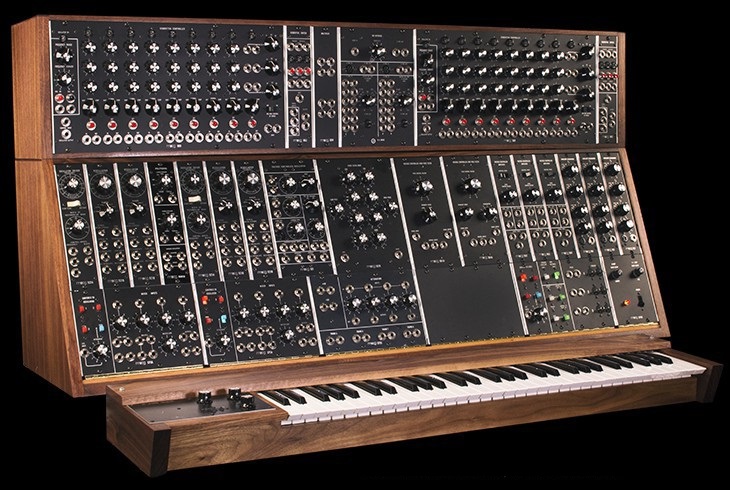
The Moog System 35 Modular Synthesizer (Photo Courtesy Moog Music)

On these systems, the configuration of the patch cables, knobs, and switches determined what sort of sound was created. Even today, the configuration for a sound on a synthesizer is called a patch, though it might not involve any cables or plugs.

The signals between the modules were all analog, using voltages to represent musical parameters. One voltage might control the pitch, another the timbre, and a third the amplitude. Within the system, the signaling between the modules was standardized, so all of the modules were intercompatible.

The voltage compatibility didn’t always translate to other vendors. Each manufacturer implemented their own variant of the analog interface, tailored to their specific needs. There was little agreement as to how the interface worked. While instruments could be connected, there was no guarantee that they would respond the same way. There were simply too many permutations to allow easy communication.

In the late 1970’s, Herbie Hancock was exploring the possibilities of synthesizers, and had a live rig that incorporated instruments from many different manufacturers. He wanted to be able to play any of them from a single custom keyboard.

Herbie Hancock's Sunlight

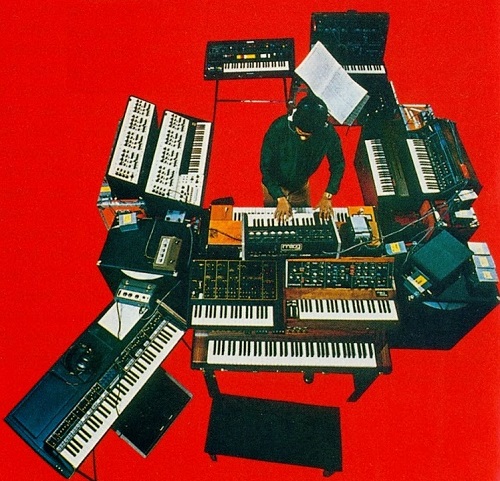
The Back Cover of Herbie Hancock’s 1978 record Sunlight

Bryan Bell, Herbie’s sound technician, designed and built a system to interface those synths, as well as manage storing and loading patches. It was expensive and primitive, but it proved the value of the underlying concepts.

Introducing Digital Systems

By the end of the 70’s, many synthesizers contained a digital microprocessor, controlling the analog circuitry, and implementing features such as automatic tuning, pattern generation (arpeggiation and sequencing), and sound storage. Roland introduced the short-lived Digital Control Bus (DCB) to allow interconnection of their synthesizers, and DIN-SYNC to synchronize drum machines, but neither was widely adopted.

In the early 1980’s, following on the concepts of DCB and DIN-SYNC, Roland joined with manufacturers, including Sequential Circuits, and Oberheim, to co-develop a new standard for connecting synthesizers. MIDI was introduced at the 1983 NAMM trade show, where a Sequential Prophet 600 interfaced with a Roland Juno 106.

MIDI gained popularity as the personal computer caught on. It was state of the art in 1984, when the Apple II and Commodore 64 were the height of home computing. As technology raced on, digital audio has become commonplace, and MIDI has been adapted and extended several times. While most modern computers lack an actual MIDI port, USB is easy to convert to MIDI with an adapter.

MIDI Devices

Before we get into the details of the protocol, let’s look at some of the devices that incorporate MIDI and introduce the terminology surrounding them.

Keyboard Synthesizer

The most obvious MIDI device is the ordinary keyboard synthesizer. For the purposes of this tutorial, we’ll be calling anything that can generate sound a synthesizer or tone generator. From a general perspective, the specific method used to generate the sound is unimportant, and there are many subtle distinctions that differentiate between instruments.

Kurzweil K2000

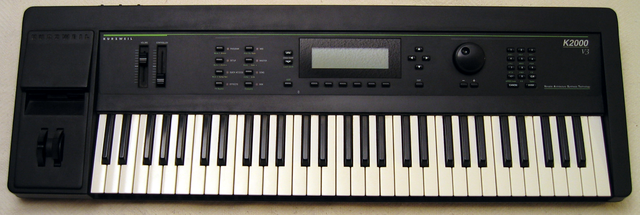
Kurzweil K2000 Synthesizer (Image courtesy wikimedia commons)

The keyboard synthesizer typically has a piano keyboard (called the controller), and an internal tone generator, which could be analog, digital, or even mechanical. The player presses a key, and the synth produces a sound in response.

Depending on the underlying technology, a synthesizer can be:

  • Monophonic - capable on playing a single note at a time, like woodwind or brass instruments.
  • Polyphonic - capable of playing multiple notes simultaneously, like a guitar, piano or organ. The number of simultaneous sounds is often limited, specified as the number of voices it can generate.
  • Multitimbral - a polyphonic synthesizer that is capable of playing different sounds simultaneously. Multitimbral instruments often have different modes for using these sounds:
    • Layering simply lets the performer play the multiple sounds at the same time, in unison.
    • A keyboard split assigns different voices to different regions of the keyboard. One example is a string bass on the left side of the keyboard, and a piano on the right side.
    • A velocity split changes sounds depending on how hard the keyboard is struck. A soft touch could result in a glass harmonica sound, while a harder hit might elicit a pyrophone.

The controller and sound generator functions don’t need to be bundled in the same unit, though. They could also be separate components.

Standalone Sound Generators

Standalone MIDI sound generators, also known as sound modules, are instruments that generate sound, but have no on-board provision for playing. They can take many forms, the two most common might be the tabletop module

Moog Minitaur

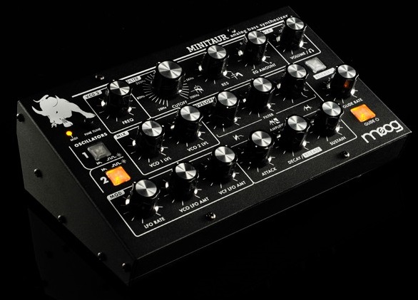
Moog Minitaur Module(image courtesty Moog Music)

and the rack-mount unit.

Toland D550 Rackmount

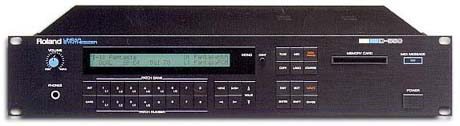
Roland D550 Rackmount Synthesizer (Image courtesy wikimedia commons)

One other type of synthesizer we’ll include in this category is the virtual or software synthesizer, a piece of software running on a computer. There are many virtual synthesizers available today, including emulations of classic, vintage instruments, and complex types of sound generation that might be impractical as dedicated standalone devices.

While the shapes differ, they are functionally equivalent. They receive commands on their MIDI input, and respond by generating sounds. They are usually used with a computer sequencer or an external MIDI controller.

Standalone Controllers

The flip-side of the standalone sound generator is the standalone MIDI controller. The most common is probably the MIDI keyboard controller.

alt text

This offers a set of piano keys, sometimes grouped with extra knobs, wheels or levers. It doesn’t generate any sound on its own, instead sending MIDI messages to an external tone generator.

MIDI controllers have evolved significantly in recent years, particularly as virtual instruments have proliferated. A MIDI controller allows the player to access settings using physical controls. They can turn a physical knob instead instead of reaching for the mouse. A wide variety of controllers are now available, reflecting many different musical applications. These include electronic drumsets, saxophones, mixing consoles, and DJ turntables.

alt text

A keyboard controller and a tabletop drum-pad controller

Drum Machine

A drum machine contains two major elements: a sound generator, and a sequencer.

alt text

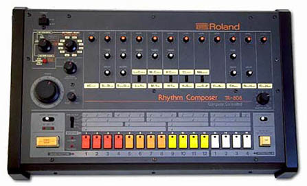
The Roland TR-808 drum machine (Image courtesy wikimedia commons)

The sound generator portion is similar to those described above, a synthesizer tailored to making drum and percussion sounds.

The sequencer is used to capture and play back drum beats, triggering the associated sound generator. Some sequencers are read-only, only playing back prerecorded rhythms – remember the “cha-cha”, “tango” and “merengue” buttons on your grandparents' parlor organ? Most drum machines are programmable, allowing the user to create their own rhythms, although the specific programming interface varies widely.

Computers

MIDI has grown up alongside the personal computer, and PCs frequently feature MIDI interfaces. MIDI was hidden in the 15-pin joystick interface on older PC soundcards, broken out to 5-pin DIN connectors with a pigtail adapter. Of course, the 15-pin joystick plug has disappeared, and joysticks now connect via USB. Conveniently enough, USB also defines a MIDI device class, so MIDI is available on modern computers.

We mentioned virtual instruments above, but there are many other types of MIDI application for the PC. Whether it’s connected with an actual MIDI port, or via USB, the personal computer is capable of running programs to serve a number of different MIDI functions.

  • Like the drum machine, a sequencer program records MIDI messages and plays them back, possibly also allowing the user to edit and rearrange the MIDI data. Sequencers take many forms, from the very simple to the extremely sophisticated.
  • Notation programs allow the user to compose music by writing in musical notation on the staff, then print the resulting scores.
  • A patch editor serves as an onscreen substitute control panel for a synthesizer. Editors are especially popular for instruments with only a small LCD for accessing the internal parameters, as the PC GUI can display the sonic parameters much more clearly.
  • The librarian is used to load, save, and organize the sounds on an instrument.

These features may all be combined in a single application. A modern sequencer might also host virtual instruments, be able to edit and organize patches, as well as record and edit MIDI and digital audio.

Other Applications

MIDI sometimes pops up on devices that aren’t strictly musical instruments. One common application is controlling stage lighting, although large light systems are more commonly controlled via the DMX-512 serial protocol.

Musicians are also a creative bunch of people. There are many examples of people building unique instruments, enabled by the ubiquity of MIDI.

The MIDI Standard

The MIDI standard is maintained by the MIDI Manufacturers Association (MMA), who have an online presence at MIDI.org. The MIDI specification itself is a printed document, available from the MMA for $60. This is a substantial document, which provides in-depth descriptions of many aspects of the protocol.

MIDI Specification Book

If you’re casually experiementing with MIDI, there are plenty of reference materials available online. However, if you’re serious about making MIDI instruments, this document is worth having. Joining the MMA as a manufacturer also grants you a System Exclusive ID code.

Hardware & Electronic Implementation

MIDI Hardware

One of the design goals of MIDI was that it needed to be relatively inexpensive. When MIDI was created, most electronic instruments were already built around a microprocessor system, so MIDI was defined as a micro-to-micro digital communication buss. One goal was that the hardware for the interface would only increase the bill of materials cost by about $5, which, by comparison to the rest of the parts, was an insignificant cost.

Physical Implementation

Since electronic musical instruments already feature a number of plugs and connections, MIDI specifies one that wasn’t commonly in use at the time: the circular 5-pin DIN connector. A unique connector was selected so things couldn’t be misconnected.

5-pin DIN Connector

Note that the pins on the connector are numbered out of order – it’s as if two more pins were added between the pins of a 3-pin connector. To help keep it straight, the numbers are frequently embossed in the plastic of the connector.

To plug into that connector, you need a MIDI cable.

MIDI Cable

While the connectors have five pins, only three of them are used. If you want to wire your own MIDI cable, you’ll need two male, 5-pin DIN connectors and a length of shielded, twisted-pair (STP) cable.

A MIDI cable is connected as follows:

MIDI Cable Wiring
First ConnectorCableSecond Connector
Pin 1No ConnectionPin 1
Pin 2ShieldPin 2
Pin 3No ConnectionPin 3
Pin 4Voltage Reference LinePin 4
Pin 5Data LinePin 5

The spec defines a maximum cable length of 50 feet (15 meters).

Note: If you're looking for a 5-pin DIN cable with all five pins connected, you don't want a regular MIDI cable, as there's no guarantee that all of the pins are connected. You need a 5-Pin DIN cable. In a pinch, you can substitute a 5-pin DIN cable for a MIDI cable, but not the other way around.

Electronic Implementation

The MIDI spec contains a recommended circuit for the ports, illustrated below.

MIDI Ports Schematic

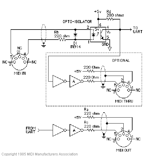
MIDI Standard Hardware (Courtesy MIDI.org)

There are three sections to this circuit.

MIDI Input

The top portion of the schematic is the MIDI input. It’s the most sophisticated part of the circuit, because it calls for an opto-isolator. The reference design specifies the long obsolete Sharp PC-900; modern designs frequently use the 6N138.

Opto-isolators are an interesting component, frequently used in interface circuitry. They allow data to be transmitted without forming an electrical connection. Internally, the incoming signal blinks an LED. The light is picked up by a phototransistor, which converts the signal back into an electronic signal. The LED and phototransistor are physically separated by a short distance. In the photo below, the gap is filled with translucent plastic.

Opto Internals

Opto-isolator internals

We’ll explain more about how the optoisolator works below, but first we need a MIDI output to connect to it.

MIDI Out

At the bottom of the schematic is the transmitting hardware, behind the MIDI Out jack. The hardware is relatively simple – the UART transmit line simply runs to a pair of logic inverters. On older microcontrollers, the I/O pins were relatively weak, and couldn’t source or sink enough current to light the LED in the optocoupler. The pair of inverters are an inexpensive way to increase the signal drive strength.

Modern microcontrollers, like the Atmel AVR, have much more robust pin circuitry. They are capable of lighting the LEDs directly, but the buffer is still sensible. Because the connector goes to the outside world, it’s possible that it could be shorted, connected incorrectly, or experience an ESD event. The buffer is a piece of inexpensive sacrificial circuitry, akin to a fuse, which can be replaced more easily than the processor.

MIDI Thru [sic]

At the center of the schematic, within the dashed line, is the MIDI thru port. You’ll notice that it’s effectively a copy of the MIDI out port, but it’s connected to the data line on the MIDI input – it transmits a copy of the incoming data, allowing multiple instruments to be daisy-chained. We’ll go into more detail about it’s usage in the topologies section.

MIDI Ports In Practice

Not every MIDI device includes all of the ports. Some devices only need to transmit or receive, only requiring a MIDI Out or In, respectively.

The MIDI thru port is also optional, sometimes omitted to reduce size or cost.

The implementation of the MIDI thru port is also subject to interpretation. While the spec calls for the hardware implementation shown above, it isn’t always followed. Some instruments use a second UART to re-transmit bytes from the input. This adds latency, which can cause timing problems in long daisy chains.

Logical Signaling

There are two signals in the schematic above that leave the page, marked “TO UART” and “FROM UART.”

UART stands for “Universal Asynchronous Receiver/Transmitter”. It is a piece of digital hardware that transports bytes between digital devices, commonly found as a peripheral on computer and microcontroller systems. It is the device that underlies a serial port, and it is also used by MIDI.

If you’re not familiar with the basics of UARTs, you can come up to speed with our Serial Communication tutorial.

The UART signals in the schematic above are at logic levels. When it is idle, it sits at a logic high state. Each byte is prefaced with a start bit (always zero), followed by 8 data bits, then one stop bit (always high). MIDI doesn’t use parity bits.

Serial Byte Breakdown

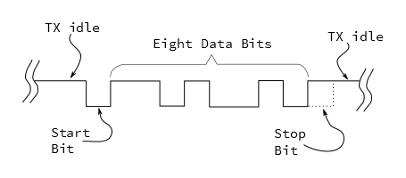
MIDI uses a clock rate of 31,250 bits per second. To send an 8-bit byte, it needs to be bookended with start and stop bits, making ten bits total. That means a byte takes about 320 microseconds to send, and the maximum throughout on a MIDI connection is 3,125 bytes per second. The average MIDI message is three bytes long, taking roughly one millisecond to transmit.

When MIDI was new, most synthesizers used discrete, external UART chips, such as the 16550 or the 8250. UARTs have since moved into the microcontroller, and they are a very common peripheral on AVR, PIC and ARM chips. UARTs can also be implemented in firmware, such as the Software Serial library for Arduino.

We’ll go into much more detail about what the bytes mean and how to interpret them in the next section.

From Output to Input

Before we move on to the messaging portion of the protocol, let’s analyze the circuit formed when an output is plugged into an input. Below we see a simplified diagram, showing an output port connected to its corresponding input.

Sending Logic High

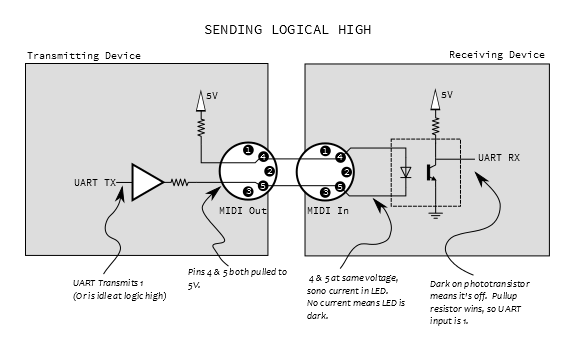
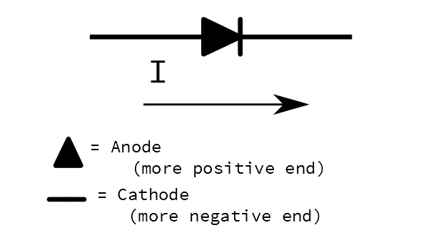
At the output, pin 4 is pulled high through a small resistor, and pin 5 is the buffered UART transmit line. On the input, these lines are tied to the anode and cathode of the LED in the opto-isolator. Since the UART output is high when not transmitting, both pins 4 and 5 will be at the same voltage, no current flows through the LED, thus it is not illuminated. When the LED is dark, the phototransistor is off, and the UART receives the voltage through the pullup, resulting in a logic one.

When the UART starts transmitting a byte, the start bit will pull pin 5 low, and current flows through the LED, illuminating it. When the LED is on, the phototransistor turns on, swamping the pullup, pulling the UART input to ground, and signaling a zero.

Sending Logic Low

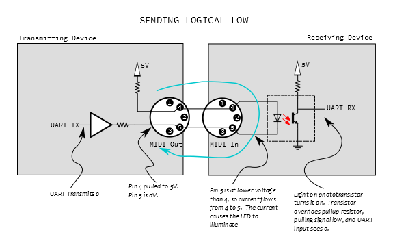
We should note here that the LED is electrically a part of the transmitting circuit. Current flows out of the transmitter, through the LED, and back to the transmitter, forming a current loop (illustrated in blue, above). There is no actual electrical connection between the transmitter and receiver, only the optical path inside the optoisolator. This is useful in helping to avoid ground loops.

Messages

As stated in earlier sections, the overarching goal of MIDI was to allow different devices to communicate, speaking a well-defined protocol. The protocol revolves around a stream of small messages. Most messages are between one and four bytes long, although some can be longer, and some information requires groups of messages.

MIDI messages fall into several categories, such as performance messages (“the performer pressed the middle C key”), information about the sounds being played (“change from the piano sound to the organ sound”), and other musical data, such as metronome or real-time clocks.

A quick word about written numbers: In the following sections, we'll be using both decimal and hexadecimal notation to represent numbers. Decimal numbers will be written normally, and the hex will be prefixed with `0x`. If you're new to hexadecimal, you can learn more about it in this tutorial .

Status or Data?

In the previous section, we discussed the UART configuration for MIDI – 31,250 bits per second, 8 data bits per byte, and 1 stop bit. MIDI uses those 8 data bits to the fullest extent!

Within a byte, each bit may be either a 0 or 1.

Bits in a Byte

One Eight-Bit Byte

Some bytes are further divided into nybbles, or 4-bit chunks. Each nybble is identified by its position within the byte. When written in hexidecimal, each nybble is represented by a character. The left hand character (made up of the higher-value bits) is known as the most-significant nybble, and the right-hand character is known as the least-significant nybble.

Nybbles in a Byte

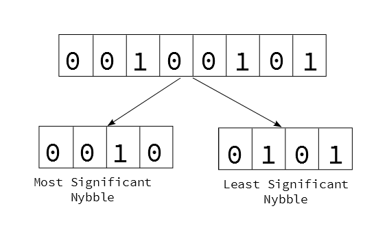
Byte divided into nybbles

Bytes of MIDI messages are divided into 2 major categories, based on the setting of the most significant bit.

Status Byte Determination

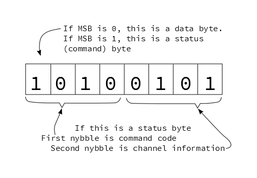
Status Byte Dissection

If the first bit is high (values between 0x80 and 0xff), it denotes a status byte. Status bytes are the commands of the MIDI stream.

  • Status bytes are further subdivided by nybble. The first nybble specifies the command type, and the second nybble specifies which the channel the command applies to.
  • There are only eight bit combinations with the MSB set (0x8 to 0xf), therefore there are eight possible status commands.
  • The 4 bits in the channel nybble are all usable, giving MIDI 16 possible channels.

If the first bit is low (values between 0x00 and 0x7f), it is a data byte, indicating parameters that correspond to a previous status byte. Because the MSB must be zero (otherwise they’d become status bytes), the data is limited to 7-bits, or the range from 0 to 127 (0x0 to 0x7f).

Statuses & Corresponding Data

Let’s look at the status bytes. We’ll start with a list, then explore each in the following sections.

MIDI Status Messages
Message TypeMS NybbleLS NybbleNumber of
Data Bytes
Data Byte 1 Data Byte 2
Note Off0x8Channel2Note NumberVelocity
Note On0x9Channel2Note NumberVelocity
Polyphonic Pressure0xAChannel2Note NumberPressure
Control Change0xBChannel2Controller NumberValue
Program Change0xCChannel1Program Number-none-
Channel Pressure0xDChannel1Pressure-none-
Pitch Bend0xEChannel2Bend LSB
(7-bits)
Bend MSB
(7-bits)
System0xFfurther specificationvariablevariablevariable

The messages with the channel number in the second nybble of the status byte are known as channel messages. Channels are often used to separate individual instruments – channel one could be a piano, two a bass, and so on. This allows a single MIDI connection to carry information for multiple destinations simultaneously. Each sound would be played by sending messages with the apprppriate value in the channel nybble.

Channel numbering leads to some confusion. With 4 bits, there are 16 possible binary values, 0 through 15 (0x0 through 0xF). Since most people start counting at one rather than zero, MIDI devices commonly (but not always) internally add an offset of one to the binary value, resulting in the range 1 to 16. If you're having trouble getting a system to communicate, you might try adjusting channels up or down by one.

Since they’re very useful, and easy to implement, we’re going to start with two of the most common types of messages: Note On/Off and System Realtime.

Note Off (0x80), Note On (0x90)

The meaning of Note On and Off messages is reasonably obvious. When a key on a keyboard is pressed, it sends a Note On message, and it sends a Note Off when the key is released. On and Off messages are also sent by other types of controllers, such as drum pads, and MIDI wind instruments.

When a synthesizer receives a Note On, it starts generating sound; the Note Off instructs it to stop.

Note On and Off are each comprised of three bytes

0xnc, 0xkk, 0xvv

Where

  • n is the command (note on (0x9) or off(0x8))
  • c is the channel (1 to 16)
  • kk is the key number (0 to 127, where middle C is key number 60)
  • vv is the striking velocity (0 to 127)

Velocity is most commonly measured using a pair of switches under each key, which are slightly offset from each other. As the key is pressed, one switch closes before the other. By measuring the time between the two switch closures, it can determine how quickly the key was moving. Some instruments don’t measure velocity, and instead transmit a fixed value for that byte, such as 0x40 (64).

We said these are simple on the surface, but there are a couple of tricky shortcuts that complicate the situation.

Running Status

In order to transmit fewer bytes, and free up some bandwidth on the connection, MIDI uses a form of shorthand. When the same status byte would be transmitted repeatedly, the protocol uses the notion of Running Status, where only the first status byte is transmitted, and successive messages simply transmit new data bytes. For example, three Note On messages would usually be:

0x90, 0x3C, 0x40
0x90, 0x3D, 0x40
0x90, 0x3E, 0x40

Using running status, the second and third status bytes are omitted:

0x90, 0x3C, 0x40, 0x3D, 0x40, 0x3E, 0x40

Although we’re illustrating this in the context of Note On/Off messages, it can apply to any status. When a new status byte arrives, it replaces the previous running status.

Implicit Note Off

To make more effective use of running status, MIDI uses a Note On command with a velocity of zero as an alias for a Note Off. For example, starting with this on/off pair

0x90, 0x3C, 0x40
0x80, 0x3C, 0x40

We can change the off byte (0x80) into an on (0x90) with zero velocity

0x90, 0x3C, 0x40
0x90, 0x3C, 0x00

Since it is now two Note On messages in a row, we can apply running status, remove the second command, and save the transmission of one byte

0x90, 0x3C, 0x40, 0x3C, 0x00

When implicit note off is used, the implied Note Off doesn’t have a velocity value. While Note Off velocity is frequently not implemented, there are times that it is an important element of a performance. In those situations, the instruments need to support it, and it might need to be explicitly enabled, often in a configuration menu.
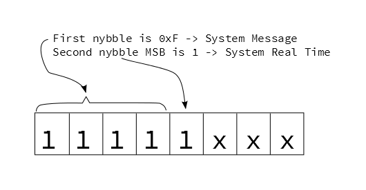

System Real Time

Another useful category is System Real Time messages. These are denoted when the MSB of the second nybble of the status byte is set (values from 0xF8 to 0xFF).

System Realtime Bit

These messages are all one byte long. They’re mostly used to synchronize sequencers, acting as a high-resolution metromone.

System Real Time Messages
TypeStatus ByteUsage
Timing Clock 0xF8 These messages represent metronimic timing, transmitted at a rate of 24 per quarter note. The actual rate is dependent on the tempo of the song.
Undefined0xF9
Start0xFA Start playing from the beginning
Continue0xFB Start playing from where last stopped
Stop 0xFC Stop playing
Undefined 0xFD
Active Sense 0xFE An optional "keep alive" message that, when implemented, can be used to detect if a transmitter has been accidentally unplugged. A transmitter sends them every 300 milliseconds. If the messages stop flowing, the recipient times out, and cleans up by stopping sequences and turning off notes that would otherwise be stuck on.
System Reset 0xFF A "panic switch" that instructs to receiver to reset to power-up condition.

Because system real time messages are one byte long, they have no data bytes, and are therefore not status bytes. They can be transmitted without interrupting running status.

Advanced Messages

This section of the tutorial is going to get deeper into MIDI messages. If that seems daunting, feel free to skip ahead to the next section, and refer back to this page when you're ready.

Polyphonic Pressure (0xA0) and Channel Pressure (0xD0)

Some MIDI controllers include a feature known as Aftertouch. While a key is being held down, the player can press harder on the key. The controller measures this, and converts it into MIDI messages.

Aftertouch comes in two flavors, with two different status messages.

The first flavor is polyphonic aftertouch, where every key on the controller is capable of sending its own independent pressure information. The messages are of the following format:

0xnc, 0xkk, 0xpp
  • n is the status (0xA)
  • c is the channel nybble
  • kk is the key number (0 to 127)
  • pp is the pressure value (0 to 127)

Polyphonic aftertouch is an uncommon feature, usually found on premium quality instruments, because every key requires a separate pressure sensor, plus the circuitry to read them all.

Much more commonly found is channel aftertouch . Instead of needing a discrete sensor per key, it uses a single, larger sensor to measure pressure on all of the keys as a group. The messages omit the key number, leaving a two-byte format

0xnc, 0xpp
  • n is the status (0xD)
  • c is the channel number
  • pp is the pressure value (0 to 127)

Pitch Bend (0xE0)

Many keyboards have a wheel or lever towards the left of the keys for pitch bend control. This control is usually spring-loaded, so it snaps back to the center of it’s range when released. This allows for both upward and downward bends.

Pitch Bend Wheel

The wheel sends pitch bend messages, of the format

0xnc, 0xLL, 0xMM
  • n is the status (0xE)
  • c is the channel number
  • LL is the 7 least-significant bits of the value
  • MM is the 7 most-significant bits of the value

You’ll notice that the bender data is actually 14 bits long, transmitted as two 7-bit data bytes. This means that the recipient needs to reassemble those bytes using binary manipulation. 14 bits results in an overall range of 214, or 0 to 16,383. Because it defaults to the center of the range, the default value for the bender is halfway through that range, at 8192 (0x2000).


Control Change (0xB0)

In addition to pitch bend, MIDI has provisions for a wider range of expressive controls, sometimes known as continuous controllers, often abbreviated CC. These are transmitted by the remaining knobs and sliders on the keyboard controller shown below.

Continuous Controllers

These controls send the following message format:

0xnc, 0xcc, 0xvv
  • n is the status (0xB)
  • c is the MIDI channel
  • cc is the controller number (0-127)
  • vv is the controller value (0-127)

Each of the controllers in the picture above is configured to send a different controller number.

Typically, the wheel next to the bender sends controller number one, assigned to modulation (or vibrato) depth. It is implemented by most instruments.

The remaining controller number assignments are another point of confusion. The MIDI specification was revised in version 2.0 to assign uses for many of the controllers, as shown on pages 2 and 3 of this document. However, this implementation is not universal, and there are ranges of unassigned controllers.

On many modern MIDI devices, the controllers are assignable. On the controller keyboard shown in the photos, the various controls can be configured to transmit different controller numbers. The flip-side is also often true – controller numbers can be mapped to particular parameters. Virtual synthesizers frequently allow the user to assign CCs to the on-screen controls. This is very flexible, but it might require configuration on both ends of the link and completely bypasses the assignments in the standard.


Program Change (0xC0)

Most synthesizers have patch storage memory, and can be told to change patches using the following command:

0xnc, 0xpp
  • n is the status (0xc)
  • c is the channel
  • pp is the patch number (0-127)

This allows for 128 sounds to be selected, but modern instruments contain many more than 128 patches. Controller #0 is used as an additional layer of addressing, interpreted as a “bank select” command. Selecting a sound on such an instrument might involve two messages: a bank select controller message, then a program change.


System Messages (0xF0)

The final status nybble is a “catch all” for data that doesn’t fit the other statuses. They all use the most significant nybble of 0xF, with the least significant nybble indicating the specific category.

We covered system realtime messages in the previous section. The messages are denoted when the MSB of the second nybble is 1. When that bit is a 0, the messages fall into two other subcategories.

System Common

If the MSB of the second second nybble is not set, this indicates a System Common message. Most of these are messages that include some additional data bytes.

System Common Messages
TypeStatus ByteNumber of
Data Bytes
Usage
Time Code Quarter Frame 0xF1 1 Indicates timing using absolute time code, primarily for synthronization with video playback systems. A single location requires eight messages to send the location in an encoded hours:minutes:seconds:frames format*.
Song Position 0xF2 2 Instructs a sequencer to jump to a new position in the song. The data bytes form a 14-bit value that expresses the location as the number of sixteenth notes from the start of the song.
Song Select 0xF3 1 Instructs a sequencer to select a new song. The data byte indicates the song.
Undefined 0xF4 0
Undefined 0xF50
Tune Request 0xF60 Requests that the reciever retune itself**.
*MIDI Time Code (MTC) is significantly complex, and beyond the scope of this tutorial. If you need to know the finer points of MTC, you should probably have your own copy of the MIDI Specification!

**While modern digital instruments are good at staying in tune, older analog synthesizers were prone to tuning drift. Some analog synthesizers had an automatic tuning operation that could be initiated with this command.
System Exclusive

If you’ve been keeping track, you’ll notice there are two status bytes not yet defined: 0xf0 and 0xf7.These are used by the System Exclusive message, often abbreviated at SysEx. SysEx provides a path to send arbitrary data over a MIDI connection. There is a group of predefined messages for complex data, like fine grained control of MIDI Time code machinery. SysEx is also used to send manufacturer defined data, such as patches, or even firmware updates.

System Exclusive messages are longer than other MIDI messages, and can be any length. The messages are of the following format:

0xF0, 0xID, 0xdd, ...... 0xF7

The message is bookended with distinct bytes.

  • It opens with the Start Of Exclusive (SOX) data byte, 0xF0.
  • The next one to three bytes after the start are an identifier.
    • Values from 0x01 to 0x7C are one-byte vendor IDs, assigned to manufacturers who were involved with MIDI at the beginning.
    • If the ID is 0x00, it’s a three-byte vendor ID - the next two bytes of the message are the value.
    • ID 0x7D is a placeholder for non-commercial entities.
    • ID 0x7E indicates a predefined Non-realtime SysEx message.
    • ID 0x7F indicates a predefined Realtime SysEx message.
  • After the ID is the data payload, sent as a stream of bytes.
  • The transfer concludes with the End of Exclusive (EOX) byte, 0xF7.

The payload data must follow the guidelines for MIDI data bytes – the MSB must not be set, so only 7 bits per byte are actually usable. If the MSB is set, it falls into three possible scenarios.

  1. An End of Exclusive byte marks the ordinary termination of the SysEx transfer.
  2. System Real Time messages may occur within the transfer without interrupting it. The recipient should handle them independently of the SysEx transfer.
  3. Other status bytes implicitly terminate the SysEx transfer and signal the start of new messages.

Troubleshooting Tip: Some inexpensive USB-to-MIDI interfaces aren’t capable of handling messages longer than four bytes. If you’re having trouble with SysEx transfers when using such an interface, it might be useful to inspect the messages on the bus with an application like MIDI Ox.


Implementation chart

With all of these different messages, MIDI has become somewhat dialectic – not every unit implements every message. A simple controller-to-synthesizer link might only need to use note on and off messages, while an on-stage pyrotechnic controller might completely ignore note messages, requiring time code, and specific SysEx commands to arm the smokebombs and flashpots.

To help the user understand what messages a specific device uses, the manual often includes a table that indicates what it can send and receive.

MIDI implementation chart

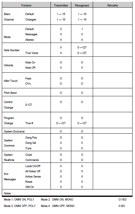
AKAI MPC500 MIDI Implementation, courtesy Akaipro.com

The chart above shows a typical implementation chart for an instrument. It tells us some notable things about the MIDI dialect spoken by this device:

  • This device transmits Note On velocity, but not note Off velocity.
  • It also uses polyphonic and/or channel aftertouch (you can select which in a configuration menu).

Topologies

Now that we’ve looked at the types of devices that offer MIDI, and the messages they use, let’s look at some of the ways they can be deployed.

Case #1: Daisy Chain

The simplest connection topology is the daisy chain, where one transmitter is connected to one or more receivers.

Daisy Chain

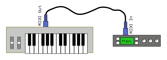
In this example, the MIDI out of a controller is connected to the MIDI in of a tone generator module. It allows the player to use the keys on the controller to play sounds from the module. The controller sends note-on, note-off and controller messages, to be interpreted into sound by the module. The communication path is unidirectional.

If the module is multitimbral, it can be set to respond on several MIDI channels, allowing the player to switch between sounds by changing the transmission channel.

We can add more downstream modules using the thru ports on the interceding devices. Thru transmits a copy of the messages received by the in port.

Daisy Chain

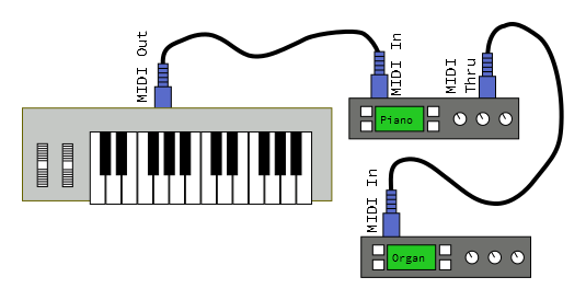
Depending on how the controller and modules are configured, there are several possibilities.

  • The modules could simply all respond together, in unison.
  • Each module could be set to respond on a different MIDI channel. By changing the channel that the controller sends, the modules can be played individually.
  • Each module could be configured to respond to particular key or velocity ranges, forming splits and layers.

Case #2: Synchronization

In this example, we want to build a percussion ensemble by connecting drum machines together.

Sync'd Drum Machines

The drum machine on the left will serve as the master clock, and the one on the right is set to receive clock messages (sometimes called clock slave or external sync mode). When the operator presses “play” on the left machine, both machines will start playing. As the tempo of the left machine is adjusted, both machines accelerate and decelerate together.

System realtime messages keep the machines in sync.

  • A start (0xFA) byte is sent to initiate playing, from the beginning of the sequence.
  • Clock (0xF8) bytes are sent regularly, serving as a shared metronome.
  • A stop (0xFC) byte halts playback.
  • Continue (0xFB) can be used to start the sequence from where it was last stopped.

Clocks may be transmitted while stopped – this allows tempo indicator LEDs to continue flashing at the correct rate.

Case #3: Computer Sequencer

The last topology we’ll look at adds a personal computer in the middle of a daisy chain.

Daisy Chain With Computer

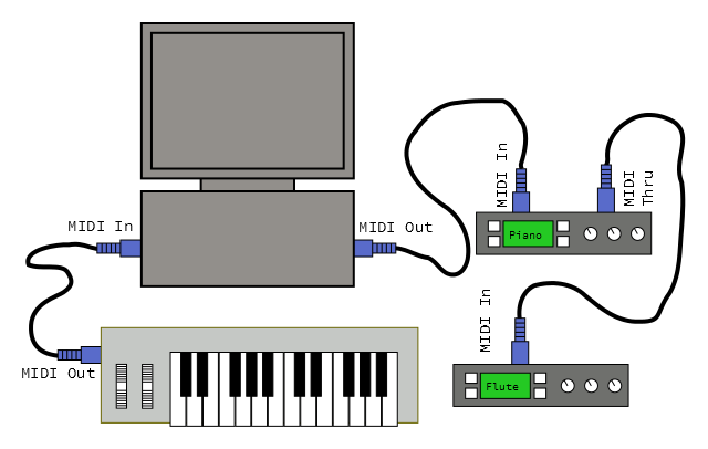
The MIDI controller keyboard is connected to the computer, and the sound generators are connected downstream from the computer. Adding a computer in the middle of the chain allows a lot of power and flexibility. MIDI sequencer software allows the user to record performances from the controller, play them back on the sound modules, and edit or arrange them into songs. Sequencers usually have tracks, which allow multiple performances to be layered. The construction of such a layered performance is known as overdubbing.

While the sequencer is recording, it receives note on and off messages from the controller. It stores them in memory, simultaneously transmitting them to the sound modules, so the performer can hear what they are playing.

During playback, the MIDI controller is unused, and the computer plays the recorded messages, again triggering the tone modules.

Implementing MIDI

Working with MIDI messages directly is much easier if you have a strong grasp on usingbinary operators to manipulate bytes. You can use bitwise AND and OR operations to mask off the status bit, and extract the channel nybble value. Bitwise-shifts are useful to manipulate the 14-bit bender data.

The code snippets below were written for Arduino. You’ll notice that bytes are transmitted using the Serial.write() method, which transmits the raw binary data, rather than converting it into a string like Serial.print() does. We’re also using the Arduino-defined byte data type, which is defined as an unsigned 8-bit value. This allows us to properly access the status bit, whereas the char type is signed – doing binary operations on signed values sometimes leads to subtle errors in the manipulating the MSB.

The software examples below are intentionally incomplete, as we’ll introduce a more complete and user-friendly option below.

Message Generation

To send a MIDI message, simply send the appropriate bytes in the right order.

System Realtime messages are the easiest to send, just feed the byte to the output.

language:c
void send_sys_rt(byte rt_byte)
{
    // We are assuming that the input is in a valid range:
    //  System RT bytes are betwen 0xF8 and 0xFF.
    //
    // More realistic code might validate each input and return an error if out of range

    Serial.write(rt_byte);
}

Channel messages are a little more complex. To form the first byte, you’d set the MS nybble to the status value, then subtract one from the channel, and put that value in the channel nybble. Send the first byte, then follow it with the appropriate number of data bytes. This snippet also includes running status – the sender keeps track of the last status byte sent in a global varible.

language:c
static byte last_status = 0;

void send_channel_message(byte command,
                          byte channel,
                          int num_data_bytes,
                          byte * data)
{
    // We are assuming that all of the inputs are in a valid range:
    //  Acceptable commands are 0x80 to 0xF0.
    // Channels must be between 1 and 16.
    // num_data_bytes should be either 1 or 2
    // data should be an array of 1 or 2 bytes, with each element constrained
    // to the 0x0 to 0x7f range.
    //
    // More realistic code might validate each input and return an error if out of range

    byte first;

    // Combine MS-nybble of command with channel nybble.
    first = (command & 0xf0) | ((channel - 1) & 0x0f);

    if(first != last_status)
    {
        Serial.write(first);
        last_status = first;
    }

    // Then send the right number of data bytes
    for(int i = 0; i < num_data_bytes; i++)
    {
        Serial.write(data[i]);
    }
}

Finally, sending system exclusive messages requires sending an identifier and data payload that are both of variable length. It must begin and also end with the proper status bytes.

language:c
void send_system_expusive(int num_id_bytes,
                          byte * id,
                          int num_data_bytes,
                          byte * data)
{
    // We are assuming that all of the inputs are in a valid range:
    // num_id_bytes should be either 1 or 3
    // num_data_bytes is not constrained, but a practical limitation might be 1000 bytes.
    // Id and data values should be constrained to the 0x0 to 0x7f range.
    //
    // More realistic code might validate each input and return an error if out of range


    // send start-of-exclusive
    Serial.write(0xF0);

    // Then send the identifier bytes
    for(int i = 0; i < num_data_bytes; i++)
    {
        Serial.write(data[i]);
    }
    // Then send the right number of data bytes
    for(int i = 0; i < num_data_bytes; i++)
    {
        Serial.write(data[i]);
    }

    // send end-of-exclusive
    Serial.write(0xF7);

}

Message Parsing

Receiving and parsing the incoming MIDI stream requires more sophistication. While features like running status, implicit note off and active sense are optional from the sender, the receiver needs to be prepared to deal with them.

A simplified finite state machine for parsing MIDI is shown below.

MIDI Bubble Diagram

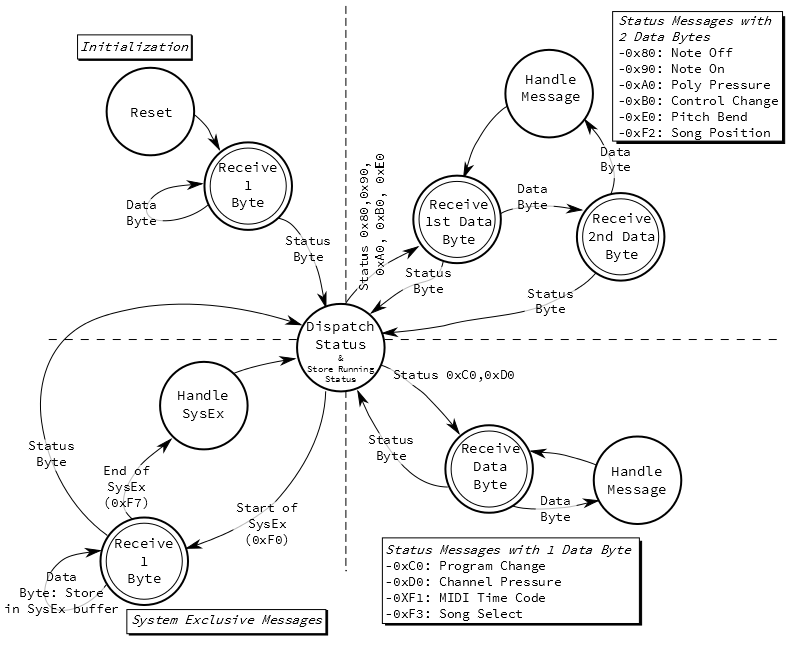
There are a few things to note

  • The system initializes and starts receiving bytes. Until it sees a status byte, the input is meaningless and is discarded. Realistically, status bytes occur fairly frequently, so this state is a temporary condition.
  • The “Dispatch Status” state decides how to handle messages based on how long they are.
    • Most status messages have one or two bytes of data.
    • System Exclusive messages can be any length, with the end marked by a “end of exclusive” byte.
  • Running status is handled by the Dispatch Status state, in conjunction with the status handling branches.
    • Dispatch Status stores the status byte, so it can be recalled when running status is used.
    • When the one-byte and two-byte branches of the FSM see repeated data bytes, they repeatedly apply the stored status.
  • At any point that the FSM is expecting a data byte, a new status could arrive instead. The previous status is discarded, and the new status dispatched instead.

You’ll notice that all of the “receive bytes” states are illustrated with a double-circle. This is shorthand for more sophisticated behavior. As we discussed previously, system realtime bytes can occur at any point. We could be expecting the velocity byte of a Note On message and get a clock byte instead. The clock is allowed to non-disruptively interrupt the parsing. The details of the receive states are shown below.

Realtime Handling Within Receive States

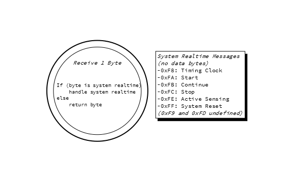
From the perspective of the parsing FSM, system realtime bytes don’t count as data or status bytes, they just get handled as they arrive.

The diagram shown above illustrates how to decode the bytes in the MIDI stream, but it doesn’t make any implication about how the receiver will respond to them. The verb “handle” is intentionally vague, as each type of device might respond differently.

Arduino Library

The FSM above is pretty complicated. Writing and debugging it means developing a pretty serious piece of software.

But there’s an easier way. Github user FortySevenEffects has written an Arduino MIDI library that makes reading and writing MIDI messages much easier. The library is flexible, and it can be configured to fit different applications.

  • It can use hardware or software serial ports (leaving the hardware serial port for printing debug messages!).
  • Incoming messages can be received by polling, or callbacks for specific messages can be installed.
  • The library can filter for messages on a specific midi channel, or receive on all channels.
  • It implements an optional “soft thru” port that can be configured to echo the input back to the output port.

It also has detailed documentation in doxygen format.

For some practical examples that demonstrate this library, take a look at the hookup guide for the SparkFun MIDI Shield.

Devising Your Own Implementation Chart

In the messages section, we discussed the MIDI implementation chart. If you’re implementing a MIDI device, you should consider writing your own chart, so you know what messages to handle. Most devices won’t implement every message, and for messages it does implement, it may still choose to ignore some. For instance, a tone generator will handle note on and off messages, but only those on its MIDI channel. For statuses that are not needed, you can simply discard the messages.

If you elect to discard messages, it’s advisable that you still handle the System Reset message (0xff) - it’s used as a “panic switch” in situations that you need things to be silent, ASAP!

Other MIDI Technologies

In addition to the communication protocol, MIDI also specifies some related technologies, with the goal of achieving greater intercompatibility. MIDI has been extended several times, to clarify parts of the messaging protocol, and to help standardize areas related to electronic musical instruments. While not an exhaustive list, we’ll discuss a couple of the common extensions below.

Standard MIDI Files

As MIDI sequencers caught on, people wanted to be able to move their song data between different sequencers. Each sequencer implemented a proprietary file format – some were able to import data from others, but it was far from universal.

The Standard MIDI File was specified as the lingua franca for sequence data interchange. The files use the SMF extension.

SMF has been widely adopted, across many operating systems. Media player programs can play them back, while full-fledged sequencers can import, edit and export SMFs.

General MIDI

Moving sequence data between platforms brings along a related problem: the MIDI communication protocol does not specify how instruments interpret patch changes, associate instruments with MIDI channels, nor implement multitimbrality. General MIDI adds some standardization to those parameters, so that different instruments will respond similarly.

General MIDI defines a standard sound set – a mapping of program change commands to specific sound patches. On all MIDI channels except 10, Program #1 would always be a grand piano patch, #2 a “bright piano”, and so on.

Channel 10 is reserved for drums, and the mapping of drum sounds to the keyboard was also defined.

General MIDI also specifies that a supporting instrument need to simultaneously allow voices on all 16 channels, and provide at least 24 voices of polyphony.

Instruments that support the General MIDI features display the General MIDI logo.

GM Logo

The General MIDI Logo

A sequence composed for the General MIDI sound set (likely stored an an SMF) will play back similarly on any General MIDI instrument. Of course, even with the standardization, there will be some variation between instruments.

General MIDI was also common on PC soundcards with an onboard wavetable synthesizer. This was playable as an instrument in itself and also used by video game soundtracks. Cell phones also feature a GM sound generator, and can use SMF files as ringtones. Today, computers and cell phones are capable of handling audio files for video game soundtracks and sound effects, and the General MIDI/SMF pairing is becoming less common.

Shortcomings

MIDI was quite successful in solving the initial problem: synthesizers from different manufacturers can communicate performance information. A performer can connect MIDI instruments, and they respond similarly. Simply being able to do that was revolutionary, and paved the way for widespread adoption of MIDI.

It’s popularity has been a mixed blessing. As MIDI caught on, it’s been revised and extended, gaining features far beyond the initial intent. In hindsight, some of these features might be overly cumbersome or anachronistic. For example, we can ship files to and from MIDI instruments using SysEx messages, but today it might be easier to build an instrument that accepts SD cards or USB thumb drives.

Let’s examine a couple of the more common complaints.

The Piano Keyboard

MIDI is based on a digital representation of the piano keyboard, and it works well for instruments that ordinarily feature a keyboard. Note on and off commands have an obvious correspondence to actuating piano keys. How they relate to how other instruments is less obvious.

As one specific example, translating a guitar performance into MIDI data is particularly tricky. Accurately converting the vibrations of a guitar string into MIDI note numbers is much harder than simply noticing that a switch has closed. While there are commercial MIDI guitars around, they’re best approached as a unique instrument, not a simple replacement for a guitar.

The piano keyboard is also intrinsically linked to the 12-tone western chromatic scale. How scales from other cultures translate into MIDI is not always obvious. There are System Exclusive messages that transmit alternate tuning information, but their implementation is uncommon.

Digital limitations

MIDI was designed using digital technology that was inexpensive the early 1980’s. More than 30 years later, it’s still being used. Many other digital technologies from that era have since disappeared – remember 5 ¼" floppy disks and monochrome, text only displays?

Computer networking has matured considerably during those 30 years. When compared to modern protocols like Ethernet or USB, MIDI is extremely primitive. The links are unidirectional, there is no provision for data integrity checking, such as a checksum or CRC, and addresses (channels) must be manually configured. The 31,250 bits-per-second links are also comparatively slow.

The flip side of this coin is that that MIDI is easy to implement on a modest microcontroller system. Serial port peripherals are found on many MCUs. The low data rate means that it’s hard to overwhelm a receiver with too much data. Since the messages are small, storing them doesn’t require much memory.

Within the messages, there are many places where the underlying data formats are also constrained.

With four bits of channel data, a MIDI buss supports a maximum of 16 channels. The usual workaround for this is to run more than one buss.

Many of the values sent by MIDI are constrained: key numbers, continuous controllers, and aftertouch values are all 7-bits long, allowing a range from 0 to 127, which can be too coarse for some parameter values. MIDI has provisions for pairing continuous controllers as an MSB and LSB to form 14-bit values, but in practice this is uncommon.

In examining the output of one commercial keyboard controller, the bender was actually only sending seven bits of data, left justified in the 14-bits of the bender messages. Moving the wheel slowly results in audible stairstepping. This is probably the resolution of the underlying ADC, an onboard peripheral of the system’s MCU.

MIDI just didn’t leave itself much room to grow.

Updates and Alternatives

The path MIDI is on has forked. The first branch keeps the message format of MIDI but transports them with newer technologies. The other branch opts to invent technologies that address the bottlenecks we explored in the last section. Below, we’ll touch on some of the more prevalent technologies from both branches.

MIDI on Newer Transports

USB was intended to replace the confusing array of ports on the back of older PCs. At one time, each peripheral attached to a PC used different connectors; the keyboard, mouse, modem, printer and joystick all had unique plugs. USB was designed as a single hot-swappable connector that could serve all of those functions. USB became commonplace in the early 2000’s.

In addition to the preipherals mentioned above, the USB specification include a device class for MIDI ports.

At around the same time, Firewire (AKA IEEE-1394) was also deployed. It was a similar to USB, but targeted at higher bandwidth multimedia applications. As a multimedia-oriented interface, MIDI was a natural fit. In the initial deployments, Firewire had the advantage of much higher bandwidth than USB – 400 Mbit/S for 1394, vs. 12 Mbit/S for USB.

The USB and Firewire implementations of MIDI are similar. The UART and DIN connectors are replaced with the respective buss interface and plug. The messages exchanged, however, are still MIDI messages, wrapped up as USB or Firewire transactions. The MIDI messaging is essentially unchanged. This allows for backwards compatibility, but does nothing to address the shortcomings of MIDI.

These adapted protocols ultimately met quite different fates.

USB is used widely, and continues to evolve. In the USB 2.0 revision, a 480 MBit/S high-speed option was added, addressing the speed advantage that 1394 had over USB. Many newer MIDI devices feature a USB port instead of (or in addition to) regular MIDI ports. There are also standalone USB-to-MIDI interface adapters, for backwards compatibility.

USB-to-MIDI Box

USB to MIDI adapter

Apple was the driving force behind Firewire, but they have more recently switched to theThunderbolt andLightning interfaces. As a result, Firewire is declining in populatiry.

Web MIDI

Introcuced by the World Wide Web Consortium as part of HTML5, Web MIDI is an extension of HTML that allows web pages to access MIDI devices on a user’s PC. The page can discover MIDI ports, then use them as inputs and outputs.

The synthesizer below is an example of a Web MIDI application. It uses Web MIDI to discover the MIDI ports on the PC. Once the user selects a port, the synthesizer is playable from an attached MIDI controller. It uses the Web Audio API to generate sounds.

Web MIDI Screenshot

If you want to try it for yourself, click here.

Along with several demonstrations of Web MIDI and Web Audio, this example comes from webaudiodemos.appspot.com. The author, Chris Wilson, hosts the source in his GitHub repositories.

Other Standards

While MIDI is being adapted to new uses, sometimes it’s easier to start with a blank slate.

Soundfonts and Downloadable Sounds

Growing on the ideas that lead to GM, Soundfonts are files that allow for the interchange of sound data between synthesizers. Rather than just using a number to request a type of sound, the sample data and related parameters are all sent together, making the sound itself transportable.

The SoundFont was developed my E-Mu Systems and Creative Labs, first implemented by the SoundBlaster AWE32 soundcard. The Downloadable Sound (DLS) is a similar concept for sound data transport adopted by the MMA.

DMX-512

Some vendors adapted MIDI to control stage lights, but it’s a secondary use of the protocol. MIDI has no intrinsic messages or structures to represent lighting-related information, and the defined maximum cable length of 50 feet is too short for large lighting rigs.

DMX-512 was specified in 1986 as a lighting control protocol. Like MIDI, it uses a unidirectional daisy-chain of devices. Unlike MIDI, it uses a differential RS-485 electrical interface, allowing for much longer cable runs. It also uses a very different address scheme, supporting up to 512 devices on a single bus.

DMX Network

The messaging protocol on the chain is actually much simpler than MIDI. The controller bursts out a stream of bytes, up to 512 bytes long. Each device on the bus has a configured address, and the address instructs which byte in the burst is meant for it.

DMX Byte Stream

A simple light fixture might receive a single byte controlling brightness, while a motorized fixture might receive many bytes, to control panning, color, brightness, cucoloris selection, and other effects.

Open Sound Control (OSC)

Over the years, there have been many attempts to unseat MIDI. A number of new protocols have been proposed, but most didn’t catch on.

One notable exception is Open Sound Control (OSC).

OSC is a project of the UC Berkeley Center for New Music and Audio Technology (CMNAT). Compared to MIDI, it works at a very high level and leverages modern networking and data-structure practices. The usual transport is Ethernet, though it can be adapted to use SLIP over serial ports. The data structures are hierarchical and open-ended.

The OSC page on Wikipedia has lists of hardware and software that implement OSC.

OSC may suffer the reverse problem of MIDI: whereas MIDI is tightly constrained and messages are standardized, OSC is extremely open, allowing different instances to specify their own dialects, with less regard for interoperability. SYN is a proposed common dialect to be used between controllers and synthesizers.

Resources and Going Further

Resources

If you’re interested in building your own MIDI system, we have some products to help you get started.

  • If you want to build your own MIDI device, you can start with the Arduino-compatible MIDI Shield. The hookup guide for the shield has several example sketches.
  • If the shield is overkill, we’ve also got the raw MIDI connector.
  • If you’d like to skip the DIN connectors altogether, the FreeSoC2 and Teensy both offer class-compliant USB-MIDI endpoint implementations.
  • Dr. Bleep added MIDI to the second revision of the Bleep Drum.

Going Further

  • MIDI.org is the official website of the MIDI Manufacturer’s Association.
  • If you’re doing MIDI with an Arduino, the 47 Effects MIDI library handles the messaging layer for you. It’s user friendly and very configurable.
  • MIDI devices have long been a mainstay of DIY microcontroller projects. The MIDIbox is a platform for building a wide variety of MIDI devices.
  • Some ponderings on the finite state machine.
  • The MIDI Article at Wikipedia.
  • If you’re really serious about MIDI, you might want a printed copy of the Complete MIDI 1.0 Detailed Specification.

learn.sparkfun.com |CC BY-SA 3.0 | SparkFun Electronics | Niwot, Colorado


LSM303C 6DoF Hookup Guide

$
0
0

LSM303C 6DoF Hookup Guide a learn.sparkfun.com tutorial

Available online at: http://sfe.io/t418

Introduction

The LSM303C is a 6 degrees of freedom (6DOF) inertial measurement unit (IMU) in a sigle package. It houses a 3-axis accelerometer, and a 3-axis magnetometer. The range of each sensor is configurable: the accelerometer’s scale can be set to ±2g, ±4g, ±6g, or ±8g, and the magnetometer has full-scale range of ±16 gauss.

LSM303C Breakout

LSM303C Breakout Board

The LSM303C supports I2C and SPI. This tutorial focuses on using this device in I2C mode, but will briefly describe how to use SPI.

Covered In This Tutorial

First we’ll introduce you to the breakout board. Then we’ll switch over to example code and show you how to interface with the board using an Arduino and our SparkFun LSM303C 6 DOF IMU Breakout Arduino Library.

The tutorial is split into the following sections:

Required Materials

This tutorial explains how to use the LSM303C Breakout Board with an Arduino. To follow along, you’ll need the following materials:

The LSM303C is a 2.5V device! Supplying voltages greater than 4.8V can permanently damage the IC. InvenSense recommends running from 1.9V to 3.6V. As long as your Arduino has a 3.3V supply output, you shouldn't need any extra level shifting. See our [logic level tutorial](tutorials/62) for more info if you aren't using a 3.3V system.

Suggested Reading

If you’re not familiar with some of the concepts below, we recommend checking out that tutorial before continuing on.

Hardware Overview

The Pinout

The LSM303C 6 DOF Breakout has 10 plated through hole connections.

LSM303C BOB top view

Top View of LSM303C Breakout Board

The following table summarizes all of the plated through hole connections on the breakout board:

Pin LabelPin FunctionNotes
GNDGround reference+0V
VDD_IOPower supply for I/O pins1.71V up to VDD + 0.1V
SDA/
SDI/
SDO
I2C serial data
SPI serial data input
3-wire interface serial data output
ST calls the second serial interface SPI, but it's really a half-duplex variant that uses the same pin for MISO and for MOSI. Note that all 3 data signals are the same pin.
SCL/
SCLK
I2C serial clock
SPI serial port clock
100 or 400 kHz I2C
Up to 10 MHz SPI
INT_XLAccelerometer interrupt signalThe functions, the threshold and the timing of this interrupt are configurable.
DRDYData readyConfigurable output to indicate when accelerometer or magnetometer data is ready.
CS_XLAccelerometer: SPI enable
I2C/SPI mode selection
1: SPI idle mode / I2C communication enabled;
0: SPI communication mode / I2C disabled
VDD Power supply1.9V to 3.6V
CS_MAGMagnetometer: SPI enable
I2C/SPI mode selection
1: SPI idle mode / I2C communication enabled;
0: SPI communication mode / I2C disabled
INT_MAG Magnetometer interrupt signalThe functions, the threshold and the timing of this interrupt are configurable.

Power Supply

The LSM303C breakout has three power supply plated thru-hole connections: a 0V reference (GND), a core supply (VDD), and an IO supply (VDD_IO). The core of the IC can be powered from 1.9-3.6V. The IO must be given a potential of at least 1.71V up to the core supply voltage plus 0.1V. This dual supply setup eliminates the need for external voltage level translation. A 3.3V rail can power most of the device while still being able to communicate with a 1.8V processor without drawing all of its power from that lower voltage rail.

Communication

The LSM303C communicates over I2C or ‘SPI’ using the same plated thru-hole connections. The implementation of ‘SPI’ on the LSM303C isn’t standard; it’s a half-duplex variant. Standard SPI has a MOSI and a MISO signal. Both of these are found on the single SDA/SDI/SDO connection. The more common Arduino variants don’t have hardware that directly supports this, so we are bit banging in our library. Your system may be compatible, so we didn’t add external components to get the hardware to work with the Atmel SPI hardware. This connection is also used as the SDA connection for I2C. Testing showed that the implementation of this IO acts like an open-drain like is common with I2C. This means that a pull-up resistor is needed for both SPI and I2C. The breakout includes this pull-up. Both communication modes share the same clock line (SCL/SCLK).

The LSM303C is implemented as two separate cores on the same die. The accelerometer and magnetometer have their own chip select lines. In I2C mode, they have their own unique addresses. The accelerometer is at 0x1D, and the magnetometer is at 0x1E.

Interrupts

There are a variety of interrupts on the LSM303C. The system can be configured to generate an interrupt signal for free-fall, motion detection and magnetic field detection. The actual function of the two interrupt pins (INT_XL & INT_MAG) are highly configurable through either the I2C or SPI interfaces. They can be active high or low, latching or non-latching, etc. This advanced topic won’t be covered in this hookup guide. Please reference the datasheet for more information.

The Jumper

In many cases, especially Arduino related, you won’t have multiple lower voltage rails. For these cases we’ve included SJ2. Your board comes with this jumper closed with a trace by default. This connects VDD_IO and VDD.

VDD & VDD_IO jumper

Closeup of voltage jumper

The intention of this jumper is to allow the end user to power use the board and begin developing right out of the box. To disable any of these jumpers, whip out your handy hobby knife, and carefully cut the small traces between the two pads. You may then connect VDD_IO to whatever power rial you desire.

Hardware Assembly

I2C Example

The basic use case for the LSM303C requires 4 connections to the µController or µProcessor; power, ground, I2C clock and data. The following images shows how we used a SparkFun FTDI Basic Breakout, and an 3.3V Arduino Pro Mini to power and interface to a LSM303C 6 DOF Breakout board.

LSM303C and Arduino Mini

An LSM303C wired up to and Arduino Pro Mini for the MinimalistExample (IIC)

Make connections to the breakout anyway that makes you happy. The board in the above photo has a straight header soldered to it. We could have used a right angle header, or wire, etc. Please note that different mounting orientations will alter the orientation of the axes. Make sure your code matches the physical orientation for your projects.

For this demo, we made the following connections:

Arduino Pro MiniLSM303C BreakoutNotes
VCCVDD+3.3V
GNDGND+0V
SDASDA/SDI/SDOSerial data @ +3.3V CMOS logic
SCLSCL/SCLKSerial clock @ +3.3V CMOS logic

The whole system in our testing was powered via USB through the FTDI basic.

USB to FTDI to Pro Mini to I2C LSM303C Breakout Fritzing diagram

Electrical connections for demo

SPI Example

Four hardware changes need to be made to interface the sensor using SPI. Move the SDA/SDI/SDO connection from SDA on the Arduino Pro Mini to digital pin 10, move the SCK/SCLK connection from SCL on the Arduino Pro Mini to digital pin 11, and add the two chip select lines.

Arduino Pro MiniLSM303C BreakoutNotes
VCCVDD+3.3V
GNDGND+0V
Digital 10SDA/SDI/SDOSerial data @ +3.3V CMOS logic
Digital 11SCL/SCLKSerial clock @ +3.3V CMOS logic
Digital 12CS_XLAccelerometer chip select @ +3.3V CMOS logic
Digital 13CS_MAGMagnetometer chip select @ +3.3V CMOS logic

SPI Hookup

Example of a Pro Mini wired up for SPI


USB to FTDI to Pro Mini to SPI LSM303C Breakout Fritzing diagram

Connecting for SPI interface

Installing the Arduino Library

Download and Install the Library

Visit the GitHub repository to download the most recent version of the libraries, or click the link below:

Download the LSM303C Arduino Libraries

For help installing the library, check out our Installing an Arduino Library tutorial. You might find it easier to use the Arduino IDE library manager if you are running a modern release, but feel free to use any method in the tutorial.

The example Arduino code allows you to do things like read the magnetometer in all 3 axis, read the accelerometer in all 3 axis, and read the temperature of the die in Fahrenheit and Celsius.

Running the Minimalist Example

Now, you can now run the example sketches. Open File ⇒ Examples ⇒ SparkFun LSM303C 6 DOF IMU Breakout ⇒ MinimalistExample. This sketch is a simple as possible other than a little error checking.

The setup function configures the Arduino’s serial port to 115200 baud and configures the LSM303C to some reasonable defaults.


LSM303C myIMU;

void setup()
{
  Serial.begin(115200);
  if (myIMU.begin() != IMU_SUCCESS)
  {
    Serial.println("Failed setup.");
    while(1);
  }
}

The loop function sequentially prints out the x, y, and z vales measured by the accelerometer, then the gyroscope, and then the magnetometer. This is followed up by the temperature of the die in degrees Celsius and Fahrenheit. All values are rounded to 4 digits past the decimal point.


void loop()
{
  //Get all parameters
  Serial.print("\nAccelerometer:\n");
  Serial.print(" X = ");
  Serial.println(myIMU.readAccelX(), 4);
  Serial.print(" Y = ");
  Serial.println(myIMU.readAccelY(), 4);
  Serial.print(" Z = ");
  Serial.println(myIMU.readAccelZ(), 4);

  // Not supported by hardware, so will return NAN
  Serial.print("\nGyroscope:\n");
  Serial.print(" X = ");
  Serial.println(myIMU.readGyroX(), 4);
  Serial.print(" Y = ");
  Serial.println(myIMU.readGyroY(), 4);
  Serial.print(" Z = ");
  Serial.println(myIMU.readGyroZ(), 4);

  Serial.print("\nMagnetometer:\n");
  Serial.print(" X = ");
  Serial.println(myIMU.readMagX(), 4);
  Serial.print(" Y = ");
  Serial.println(myIMU.readMagY(), 4);
  Serial.print(" Z = ");
  Serial.println(myIMU.readMagZ(), 4);

  Serial.print("\nThermometer:\n");
  Serial.print(" Degrees C = ");
  Serial.println(myIMU.readTempC(), 4);
  Serial.print(" Degrees F = ");
  Serial.println(myIMU.readTempF(), 4);

  delay(1000);
}

Here is some sample output:


Accelerometer:
 X = 56.7017
 Y = 42.7856
 Z = 946.2891

Gyroscope:
 X = nan
 Y = nan
 Z = nan

Magnetometer:
 X = -0.2051
 Y = 0.0527
 Z = 0.0742

Thermometer:
 Degrees C = 24.5000
 Degrees F = 76.1000

You may have noticed that gyro data is printed despite there not being a gyro on this board. If a value is not available, the library functions will return nan (not a number). In this case the LSM303C doesn’t have a gyroscope, but it still returns a value for a consistent IMU interface. Any IMU library that implements the SparkFunIMU abstract class can be swapped out without having to change the code that uses the library. If at some point in the future it is determined that a project needs more or less degrees of freedom (and is coded with error checking) the code change is trivial. Change #include “SparkFunLSM303C.h” to #include “SparkFun<some other sensor>.h”, and LSM303C myIMU; to <some other sensor> myIMU. If for whatever reason the sensor doesn’t have valid data ready for a sensor that does exist, it will also return nan. This indicates that the value is undefined.

Running the Configure Example

By default, the easy to configure example is configured exactly the same as the minimalist example. Here is the code that differentiates the two examples, the setup:


void setup() {
  Serial.begin(115200);

  if (myIMU.begin(
  ///// Interface mode options
    //MODE_SPI,
    MODE_I2C,

  ///// Magnetometer output data rate options
    //MAG_DO_0_625_Hz,
    //MAG_DO_1_25_Hz,
    //MAG_DO_2_5_Hz,
    //MAG_DO_5_Hz,
    //MAG_DO_10_Hz,
    //MAG_DO_20_hZ,
    MAG_DO_40_Hz,
    //MAG_DO_80_Hz,

  ///// Magnetic field full scale options
    //MAG_FS_4_Ga,
    //MAG_FS_8_Ga,
    //MAG_FS_12_Ga,
    MAG_FS_16_Ga,

  ///// Magnetometer block data updating options
    //MAG_BDU_DISABLE,
    MAG_BDU_ENABLE,

  ///// Magnetometer X/Y axes ouput data rate
    //MAG_OMXY_LOW_POWER,
    //MAG_OMXY_MEDIUM_PERFORMANCE,
    MAG_OMXY_HIGH_PERFORMANCE,
    //MAG_OMXY_ULTRA_HIGH_PERFORMANCE,

  ///// Magnetometer Z axis ouput data rate
    //MAG_OMZ_LOW_PW,
    //MAG_OMZ_MEDIUM_PERFORMANCE,
    MAG_OMZ_HIGH_PERFORMANCE,
    //MAG_OMZ_ULTRA_HIGH_PERFORMANCE,

  ///// Magnetometer run mode
    MAG_MD_CONTINUOUS,
    //MAG_MD_SINGLE,
    //MAG_MD_POWER_DOWN_1,
    //MAG_MD_POWER_DOWN_2,

  ///// Acceleration full scale
    ACC_FS_2g,
    //ACC_FS_4g,
    //ACC_FS_8g,

  ///// Accelerometer block data updating
    //ACC_BDU_DISABLE,
    ACC_BDU_ENABLE,

  ///// Enable X, Y, and/or Z axis
    //ACC_DISABLE_ALL,
    //ACC_X_ENABLE,
    //ACC_Y_ENABLE,
    //ACC_Z_ENABLE,
    //ACC_X_ENABLE|ACC_Y_ENABLE,
    //ACC_X_ENABLE|ACC_Z_ENABLE,
    //ACC_Y_ENABLE|ACC_Z_ENABLE,
    ACC_X_ENABLE|ACC_Y_ENABLE|ACC_Z_ENABLE,

  ///// Accelerometer output data rate
    //ACC_ODR_POWER_DOWN
    //ACC_ODR_10_Hz
    //ACC_ODR_50_Hz
    ACC_ODR_100_Hz
    //ACC_ODR_200_Hz
    //ACC_ODR_400_Hz
    //ACC_ODR_800_Hz
    ) != IMU_SUCCESS)
  {
    Serial.println("Failed setup.");
    while(1);  // Stop here
  }
}

This setup function exposes all of the configuration options necessary to read the magnetometer and accelerometer. See the datasheet for more advanced configuration. To change a configuration option, uncomment the desired option in that section, and remove or comment out all other options in that section. For example, if you wanted to use the SPI interface, you would change that section to look like the following.


  ///// Interface mode options
    MODE_SPI,
    //MODE_I2C,

After uploading the sketch, open the serial monitor or your favorite terminal emulator and you should start seeing something similar to the following repeating over and over once per second.


Accelerometer:
 X = 64.5752
 Y = 31.4941
 Z = 943.1152

Magnetometer:
 X = -0.2085
 Y = 0.0425
 Z = 0.0972

Thermometer:
 Degrees C = 25.3750
 Degrees F = 77.6750

In the setup that this data capture came from, the breakout board was sitting roughly flat on a desk. This orients the z-axis parallel to the earths gravitational field of 1,000 mg. This is seen by the z-axis value of around 943. If the LSM303C were in free fall, the z-axis component would be 0 g, because it wouldn’t be accelerating. Since the sensor isn’t in free fall, it is measuring an effective acceleration of 1 g in the positive z direction up out of the table.

More Library Details

Common IMU Interface

This library does the C++ ‘equivalent’ of implementing a common interface or template. It does this by implementing the pure virtual methods of the SparkFunIMU class. This strays from the pure definition of an abstract because not all of the methods are purely virtual. We’ve strayed from this to give unimplemented methods a default behavior. In less technical terms, we’ve provided a common set of basic functions that any IMU should have.


virtual float readGyroX()  { return NAN; }
virtual float readGyroY()  { return NAN; }
virtual float readGyroZ()  { return NAN; }
virtual float readAccelX() { return NAN; }
virtual float readAccelY() { return NAN; }
virtual float readAccelZ() { return NAN; }
virtual float readMagX()   { return NAN; }
virtual float readMagY()   { return NAN; }
virtual float readMagZ()   { return NAN; }
virtual float readTempC()  { return NAN; }
virtual float readTempF()  { return NAN; }

The LSM303C provides useful definitions for all of these methods except for the ones that read the gyroscope, since the LSM303C doesn’t have a gyroscope. If you were to call readGyroX(), the default definition would be used, and it would return Not ANumber (NAN). This is useful because, if you write your code to use these functions and later decide to use a different IMU that also implements this interface, you only have to change a few words, and all of the code will work with the new sensor.

LSM303C Types

This library is written a little to the computer science object-oriented, encapsulation-type safety side, and a little less to the code size or speed optimized side. To provide type safety and improve readability, LSM303CTypes.h was written. In this header file, many types are defined, all registers are defined to types with descriptive names. As are all of the values you might want to write to the registers. Here is a simple example:


typedef enum
{
  ACC_I2C_ADDR = 0x1D,
  MAG_I2C_ADDR = 0x1E
} I2C_ADDR_t

The first keyword there, typedef, is used in C and C++ to define more complex types out of existing types. In this case a type named I2C_ADDR_t is defined to be an enumeration with the enum keyword. An enumeration is a list of explicitly named integral type constants. They are guarenteed to be a variable large enough to hold an int type, but what they really are depends on the compiler. For avr-gcc there are compiler switches that can change the actual value used. In this case there are two valid values for a variable of type I2C_ADDR_t; ACC_I2C_ADDR and MAG_I2C_ADDR. ACC_I2C_ADDR is short for “accelerometer (Inter-Integrated Circuit (I2C) address”. Arduino will interrpret that value to be 0x1D.

Consider the following two function prototypes:


uint8_t  I2C_ByteWrite(I2C_ADDR_t, uint8_t, uint8_t);
uint8_t  I2C_ByteWrite(int, uint8_t, uint8_t);

Both versions of that function are capable of accepting the values 0x1D and 0x1E. The main difference is that the first prototype is type safe. The first parameter has to be of type I2C_ADDR_t. This type only has two valid values, ACC_I2C_ADDR and ACC_I2C_ADDR. If you try and pass any other value without explicitly casting it your code won’t compile. You cannot make a mistake that can be loaded onto your Arduino. The avr-gcc toolchain that comes with the Arduino IDE will not let you make that mistake.

The first parameter of the second function prototype can be any int, including the values 0x1D and 0x1E, but not limited to those valid values. Sure your code could handle unexpected values, but what should it do about it? Strobe out an error message in Morse code on an LED? Lock up? This type unsafe code can allow runtime errors to get onto your microcontroller and cause strange bugs. The configure example was designed to show all of the common options, so referencing this header isn’t typically needed. The extra complexity is ‘hidden’ away where you only see it if you go looking for it.

Debug Macros

Also in the library is a header file named DebugMacros.h. As the name suggests this files contains the definitions of 4 macro functions used for debugging. This is a very simple tool hacked together for the use in developing this library, but is useful none the less. They don’t follow the GNU coding style (case), so they blend in more like standard functions in an attempt to hide the complexity from the beginner programmer.

PrototypeDescription
debug_print(msg, ...)Prints a labeled debug message to the serial monitor.
This macro function prepends the name of function & '::' to what Serial.print would do.
E.g. loop::Debug message
debug_prints(msg, ...)Very similar to the above function except it's shorter. No function label here.
Basically the same function as Serial.print().
debug_println(msg, ...)Very similar to the first macro function except it appends a newline character.
debug_printlns(msg, ...)Basically Serial.println(). No function label here.

These macro functions have a few advantages over the built in serial printing functions. The first is that all you have to do is change a single character to turn all of your debug statements on or off. They will be completely removed from the compiled code if turned off. This is done by defining DEBUG to be 1 (or non-zero) to enable the debug output. If DEBUG is defined to be 0, all of the debug_print<options> statements will be removed from the code by the preprocessor before compilation. The place to define the DEBUG macro is at the top of SparkFunLSM303C.cpp.

Another useful trick they can be used for is generating something similar to a stack trace. To do this, simply add debug_print(EMPTY); to each function. Pretend that there are a bunch of functions defined. Here is a stripped down code example:


void loop()
{
  debug_print(EMPTY);  // This is kind of unnecessary
  level_1_funct();
}

void level_1_funct(void)
{
  debug_print(EMPTY);
  level_2_funct();
}

void level_2_funct(void)
{
  debug_println("Example error message");
}

Running the sketch containing this code would produce the following output:

loop::level_1_funct::level_2_funct::Example error message

Along with the message saying what went wrong the code provides an in order list of all of the functions that called it. This is helpful for tracing back where the error occurred. It tells all of the recent functions involved. This isn’t as useful as a real stack trace, but it’s worth the 20 lines of code.

Resources & Going Further

Hopefully that info dump was enough to get you rolling with the LSM303C. If you need any more information, here are some more resources:

Going Further

Now that you’ve got the LSM303C up-and-running, what project are you going to incorporate motion-sensing into? Need a little inspiration? Check out some of these tutorials!

  • Dungeons and Dragons Dice Gauntlet– This project uses an accelerometer to sense a “rolling the dice” motion. You could swap in the LSM303C to add more functionality – like compass-based damage multipliers!
  • Are You Okay? Widget– Use an Electric Imp and accelerometer to create an “Are You OK” widget. A cozy piece of technology your friend or loved one can nudge to let you know they’re OK from half-a-world away.
  • Leap Motion Teardown– An IMU sensor is cool, but image-based motion sensing is the future. Check out this teardown of the miniature-Kinect-like Leap Motion!
  • Pushing Data to Data.SparkFun.com– Need an online place to store your IMU data? Check out data.sparkfun.com! This tutorial demonstrates how to use a handful of Arduino shields to post your data online.

learn.sparkfun.com |CC BY-SA 3.0 | SparkFun Electronics | Niwot, Colorado

Light Up Pennant with E-Textiles

$
0
0

Light Up Pennant with E-Textiles a learn.sparkfun.com tutorial

Available online at: http://sfe.io/t427

Introduction

Here’s a fun way to decorate a game room, classroom, or office - a twinkling pennant. Rather than walk you step-by-step through one project, we’ll be showing you some general tips for creating your own unique pennant with a few different types of LilyPad components.

alt text

Suggested Reading

This is a beginner to intermediate project, depending on the type of hardware you choose. You should be comfortable sewing a LilyPad LED using conductive thread.

Here are a few tutorials we suggest reading before you begin:

Materials and Tools

This project is pretty open ended - like a choose your own adventure! If you’d like to go with a non-programming project, we recommend using a LilyTwinkle or LilyTiny (you can always reprogram them later). You can also create this project using a LilyPad Arduino Simple Board and LEDs (or any additional LilyPad components you’d like). Choose one of the following options for your project:

Option A: Protosnap LilyTwinkle

The Protosnap LilyTwinkle is a great choice if you’d like a twinkling effect and the ability to test out the circuit before you get to sewing.

ProtoSnap - LilyTwinkle

DEV-11590
$19.95
1

Option B: LilyTiny

The LilyTiny is pre-programmed with four different modes to choose from - blink, heartbeat, breathing, and random fade, depending on which numbered petal you sew the LEDs to.

Option C: LilyPad Arduino

For the most flexibility in your project’s behavior, try programming a LilyPad Arduino Simple Board to light LEDs up in a twinkle, blink, or whatever pattern you choose. We will not be covering the programming side of things in this tutorial, for an introduction to programming take a look at one of our Programming tutorials.

Additional Supplies:

  • Felt pennant - either store bought or hand cut. We found the pennants used in this tutorial at a craft store for 99 cents each.
  • Scissors
  • Hot Glue Gun
  • Optional: Heat-N-Bond and iron for adhering shapes and letters
  • Insulating material (examples: acrylic/fabric paint, fabric glue, iron-on interfacing, or extra fabric)
  • Decorative craft supplies: extra felt, fabric, embroidery floss, beads, jewels, etc.

Step 1: Design Time

Time to get creative and decide what image you’d like to light up. Take time to sketch out ideas or collect pieces of felt, fabric, or other crafts to help you devise an interesting design. There are lots of photos online of retro pennants for sports teams to help inspire you if you are looking for a vintage style.

Planning Tips:

  • Decide if you want to see the components and stitching - strategic use of lettering or shapes can cover up the LilyPad pieces and let only the light from the LED shine through.

  • Leave enough room to sew - plan your design with enough space to attach components without crowding them too close together and risking conductive thread short circuits.

  • Lay out the pieces of your project first before attaching anything to the felt - this allows you to move things around and redesign as needed.

  • Leave easy access to the battery and/or power switch. For projects using a LilyPad Coin Cell Battery Holder - Switched, you’ll need to leave some room on the side to slide the battery in/out when replacing. For LilyPad Arduino Simple projects, the battery can stay attached, but make sure to leave space to plug in the FTDI to recharge and access to the slide switch on the LilyPad for powering on/off.


An example of a brainstorming sketch:

alt text


For the example circuit diagrams in this tutorial, we’ll be using this key:

alt text

Protosnap LilyTwinkle Example

Maya chose to make a pennant with the University of Colorado Buffaloes logo sparkle using the ProtoSnap LilyTwinkle. Here’s the layout she used to plan around the buffalo’s outline. She also decided to put the battery holder on the back of the pennant, making sure there was enough space to sew without hitting the LilyTwinkle or LEDs on the reverse side.

alt text

alt text

LilyTiny Example

Angela decided to use the LilyTiny’s breathing fade mode programmed on petal 0 to light up a robot’s eyes. She planned her circuit with two LEDs attached to one petal to make them light up at the same time. She also planned the battery holder to be attached to the reverse side of the felt.

alt text

alt text

alt text

LilyPad Arduino Example

For her mountain scene pennant, Maya planned the LEDs to light up the peaks and the LilyPad Arduino to be on the reverse side of the felt, again for easy access. She designed as much of the stitching as possible to be hidden by the felt mountain cut outs she created.

alt text

alt text

Step 2: Attach Components

Once you’ve settled on a final design layout, arrange your components on the felt. Make sure to double check that the positive (+) side of the LED is set up to connect to a numbered petal on the LilyTwinke, LilyTiny, or LilyPad Arduino, and the negative (-) sides are arranged to easily connect to the negative petal on the boards.

If you’d like to double check everything before sewing, use alligator clips to connect the components together and power up. Make sure to remove the battery before you begin sewing with conductive thread.

alt text

Using a small dab of hot glue, attach the components in place on the felt so they don’t move around while you sew. Be careful not to accidentally fill the sewing holes with glue, especially on smaller components like the LilyPad LEDs.

alt text

To help plan your stitching, use tailor’s chalk or a pen to draw stitch lines.

alt text

Step 3: Conductive Thread Connections

Make sure to unplug any power source or battery while sewing with conductive thread to avoid accidental short circuits.

alt text

Carefully sew the connections you planned, making sure to loop snugly around the sewing holes at least four times for a good electrical connection.

alt text

Step 4: Power It Up

Once all the stitching is done, check for any loose knot tails or places where the conductive thread may be accidentally touching components or other stitches. After everything checks out, insert (or plug in) the battery for the project and power it up using the ON/OFF slide switch. Examine your project for any LEDs that are not lighting up properly and recheck your connections if necessary.

alt text

alt text

Step 5: Decoration and Finishing Touches

Add some felt loops for authentic pennant feel and hang on a wall or use a wooden dowel to make a wave-able piece of team spirit.

alt text

For extra protection of your project, or if there are any spots on where thread is exposed and could use some insulation, take a look at our Insulation Techniques for e-Textiles. Since this project will most likely be hanging on a wall and not being worn, you will not have to worry as much about the project bending and short circuiting. Be aware if you plan to hang it near any metallic surface, the exposed thread or components could touch the metal and short circuit.

Resources and Going Further

Now that you’ve finished up a decorative project, how about trying a costume or wearable project?


learn.sparkfun.com |CC BY-SA 3.0 | SparkFun Electronics | Niwot, Colorado

SparkFun Line Follower Array Hookup Guide

$
0
0

SparkFun Line Follower Array Hookup Guide a learn.sparkfun.com tutorial

Available online at: http://sfe.io/t410

Introduction

The Line Follower Array is is an array of eight IR sensors that are configured and read as digital bits! In our laboratories, the RedBot shadow chassis was used as a test platform, but this product was designed as an add-on for any bot. The array features visible LEDs, so you can see what the robot sees, brightness control right on the board, and an I2C interface for reading and power control.

alt text

Features

  • 8 sensor eyes (QRE1113, like in our line sensor breakout)
  • I2C interface
  • Adjust IR brightness on the fly with a knob
  • Switch IR on and off with software
  • Switch visual indicators on and off with software
  • Invert dark/light sight with software
  • Based on the SX1509 I/O expander

Covered In this Tutorial

This tutorial will help get the line follower array connected to your bot with the Arduino IDE over I2C. It is split into the following sections:

Suggested Reading

The array acts as a stand alone I2C device pretty well. If you want to learn more about I2C or are using the RedBot kits, check out this additional material.

  • I2C Communication– The array is controlled over an I2C interface. Learn what that is here.
  • RedBot Experiment Guide– Using the RedBot with red or black chassis? Work through some experiments first in order to get going.
    • Line following experiment– One of the experiments for the RedBot is line following with only three sensors. Working through this experiment revels why eight sensors is better.
  • Counting and Converting in Binary– The sensors correspond to bit positions in a byte. Rusty on conversions? Take a look here.

Hardware Overview

The array PCB has a few pieces to note.

alt text

  1. IR brightness control and indicator – The IR PWR led shows the strength of the IR LEDs. Brighter means more IR emitted.
  2. Polarity marking– Shows getPosition() polarity.
  3. Robot vision indicators– See what the IR sensors are picking up. Note: these are not inverted by the library’s set/clearInvertBits() functions. Usage covered in Setting the Brightness
  4. Digital interface– Described in the Assembly section.
  5. I2C pull option jumper– Defaulted to 3.3V pull-up. Can be converted to 5V if necessary. See Setting the Jumpers.
  6. Mounting holes– The inner two holes fit the Shadow chassis. Others are general purpose.
  7. The IR transducers– These emit and detect IR radiation.
  8. I2C address selection– Set the jumpers in accordance with the table for a desired address.

Electrical Specifications

ParameterConditonsMinTyp.Max
Supply Current
Vcc = 5.0v
Strobing disabled
25

185
mA
Vcc = 5.0v
Strobing enabled
Running ‘MostBasicFollower’
16100160mA
Read Cycle TIme
Vcc = 5.0v
Strobing Enabled

3.2
ms
Vcc = 5.0v
Strobing Disabled
250us

Setting the Jumpers

The array has two configurable options: I2C address and I2C pull-up voltage.

I2C address

alt text

If you need to change the address of the array, move the solder jumper to set A0 and A1. The silkscreen table gives a reference. Seen in the photo, the default address is 0x3E. For example, if you want to use address 0x70, move A1 to the ‘1’ position and leave A0 at ‘0’.

I2C pull-up voltage

alt text

The I2C bus of the array is pulled up to 3.3V by default. This should work for 3.3V and 5V boards, but if you need to change it explicitly to 5V, cut the copper bridge and add a solder jumper to the “5V” side. The other jumper is included if you need to disconnect the I2C bus from the pull-ups entirely. This will only be used in specific situations, for instance if the microcontroller side has strong pull-ups and the array’s resistors need to be disabled.

Assembly

Assembly is super easy! Make the following connections with your microcontroller.

Signal/Description
Line Follower
Silkscreen
RedBot Mainboard
Silkscreen
RedBoard
Silkscreen
Power - 5v DC
5V
5V5V
GroundGNDGNDGND
I2C Data
SDA/A4A4A4 or SDA
I2C Clock
A5/SCL
A5A5 or SCL
INT(*)NCNCNC

* Note: INT pin is not required but can be connected to any input if the interrupt functionality is programmed into the SX1509 expander.

alt text

Using I2C via pins A4 and A5.

alt text

Using I2C via the dedicated SDA and SCL pins.

alt text

Connections are pin compatible with the RedBot Mainboard.

Mechanical Attachment to a Shadow Chassis

Attaching to the Shadow Chassis happens through the slot where the original three line following sensors were placed. Put 4-40 hardware through the array and hold with a finger. Hold the bolts through the slot in the shadow chassis, thumb on the 4-40 nuts, then make the electrical connections.

alt text

Hold the bolts in place with a finger

alt text

Thumb on the attaching nuts, then torque by hand or with a screwdriver

alt text

Make the electrical connections

Installing the Arduino Library

The sensor bar is basically an I2C expander with sensors, but to simplify implementation we’ve created a set of drivers to collect the data in a convenient way. Visit the GitHub repository to download the most recent version of the library, or click the link below:

Download the Line Follower Array Arduino Library

For help installing the library, check out our How To Install An Arduino Library tutorial. You’ll need to move the SparkFun_Line_Follower_Array_Arduino_Library folder into a libraries folder within your Arduino sketchbook.

Run a test example

To verify that your hookup works, load up the “RedBot Line Follower Bar Arduino Library\ReadBarOnly” by going to File>Examples>RedBot Line Follower Bar Arduino Library>ReadBarOnly.

The default values set by this sketch should work for a fresh, out-of-the-box sensor. Set the baud rate to 9600, and run the sketch. You should see the Arduino output data every second in a few different formats. If the sketch only says that the IC communication failed, double check your wiring connections.

Setting the Brightness

The knob on the sensor array is used to set the brightness of the IR LEDs. Because silly humans can’t see IR, the “IR PWR” LED is provided to give feedback for how bright the LEDs are operating, and to indicate that the regulator is functioning. This indicates what the brightness will be even if the IR illuminators are disabled in firmware.

Remember: Brighter is not always better. Calibrate your robot in the field before running.

Follow these three steps to configure the IR brightness.

Step 1: Turn the brightness down until light areas stop picking up.

alt text

Vision indicators will show above light areas when the shouldn’t. Notice B7 and B0 have illuminated.

Step 2: Turn the brightness up until dark areas start falsely picking up.

alt text

Vision indicators above dark areas will stop showing. Notice B3 has stopped illuminating

Step 3: Set the brightness somewhere between those two points.

alt text

B3 and B4 are illuminated over the line and knob’s arrow now shows a setting between the two limits. It’s ready to follow!

Core Functions of the Arduino Library

The basic library has the following parts

Object construction

Each instance of the SensorBar library needs to be constructed in the global scope for all to access.

Arguments:

Pass the device address in HEX ( unsigned 8 bit ).

Example:

For the default address of 0x3E:

SensorBar mySensorBar( 0x3E );

begin()

Use begin to start the sensor bar’s I2C expander. This use Wire.h under the hood.

begin() takes no arguments.

Return:

Returns success message (unsigned 8 bit).

returns 1 if it was able to communicate with the sensor bar or 0 if it had troubles. In the example ReadBarOnly the sketch is held if the sensor did not respond.

After .begin(); has been run, the sensor bar is ready to start reading data. Place it in the setup() section to run once.

Example:

language:c
uint8_t returnStatus = mySensorBar.begin();
if(returnStatus)
{
  Serial.println("sx1509 IC communication OK");
}
else
{
  Serial.println("sx1509 IC communication FAILED!");
}
Serial.println();

getRaw()

Get a reading from the array as a single 8 bit word where each bit represents an IR sensor. If the sensor’s lights show: ON, ON, ON, ON, OFF, ON, ON, ON, this function will return 0xF7 matching the bit positions on the silkscreen. If InvertBits has been set though, the result will be 0x08.

Notice that the silkscreen labels b7 through b0 represent the same bits of this raw data.

getRaw() takes no arguments.

Return:

Returns the states of the IR detectors, as bits of a byte (unsigned 8 bit).

Example:

language:c
//Get the data from the sensor bar.
uint8_t rawValue = mySensorBar.getRaw();

Get the states and place in the temporary variable rawValue

getPosition()

Use to get the data as as a vector to the average of detected points. Returns a signed 8 bit number, -127 to 127.

For example, if the center two bits (b4 and b3) detect line, the average will be 0, or centered. If the left four (b7 through b4) detect line, the result will be an average to the left (-79). If only the left most sensor detects line, b7, the result will be -127. Use the silkscreen axis on the sensor bar to assist interpretation.

Note that if InvertBits does not match the line/field colors, the result of getPosition() will not have meaning. This is because multiple detected positions get averaged to come up with a vector, and an inverted setting means basically all the positions are detected and average near zero (center).

getPosition() takes no arguments.

Return:

Position as a signed 8 bit integer, ranged: -127 to 127.

Example:

language:c
//Print the position
Serial.print("Position (-127 to 127): ");
Serial.println(mySensorBar.getPosition());

getDensity()

Use to get the number of sensors that are detecting a line.

This is useful for detecting validity of the perceived line or to detect stop conditions, such as if the robot has been picked up.

getDensity() takes no arguments.

Return:

Returns an 8-bit unsigned integer ranged 0 through 8.

Example:

language:c
//Print the density
Serial.print("Density, bits detected (of 8): ");
Serial.println(mySensorBar.getDensity());

setBarStrobe() and clearBarStrobe()

Use to turn on and off the bar’s IR strobing to save power.

Note: If BarStrobe is set, the feedback indicators only show the value during the time the robot is actively reading the line, but it can save a bunch of power.

setBarStrobe() and clearBarStrobe take no arguments and return void.

Example:

language:c
//For this demo, the IR will only be turned on during reads.
mySensorBar.setBarStrobe();
//Other option: Command to run all the time
//mySensorBar.clearBarStrobe();

Also note that a read operation takes 2-3x longer with BarStrobe set, as the library has to enable and disable the LEDs. If extremely rapid reads are required, clear the BarStrobe.

setInvertBits() and clearInvertBits()

Use to reverse the perceived line/field color scheme. With inversion cleared, the sensor is looking for a dark line on light background. With inversion set, it looks for a light line on a dark background.

Note: The bar's vision indicators are NOT reversed by this function, only how the library uses the data.

setInvertBits() and clearInvertBits() take no arguments and return void.

Example:

language:c
//Default dark on light surface
mySensorBar.clearInvertBits();
//Other option: light line on dark
//mySensorBar.setInvertBits();

Extra Library Function: The Circular Buffer

The arduino library actually contains two classes. The first (discussed above) does all the reading and configuration of the actual sensor. The second is a data structure for creating and holding a buffer of data.

The structure is a circular buffer where, when full, new data overwrites the oldest data and all access to the data is referenced from the newest piece of data.

Object Construction

Construct the buffer objects in the global scope.

Arguments:

Pass the maximum size of the buffer to create. Argument is type unsigned 16 bit integer, but size must be limited to the size of memory available.

getPosition() takes no arguments.

Example:

language:c
#define CBUFFER_SIZE 100

//...

CircularBuffer positionHistory(CBUFFER_SIZE);

getElement()

Read the data in the buffer at some depth from newest.

Arguments:

Pass the element number to get as unsigned 16 bit integer. The newest element is referenced as 0.

Return:

Element value as signed integer.

pushElement()

Add a new piece of data to the buffer.

Arguments:

Pass the value to push into the buffer as signed 16 bit integer.

pushElement returns void.

Example:

language:c
//Read data from the sensor and put it in the buffer.
positionHistory.pushElement( mySensorBar.getPosition());

averageLast()

Average some number of the most recent entries.

Arguments:

Pass number of elements to average as unsigned 16 bit integer.

Return:

The mathematical average of the newest elements as signed 16 bit integer.

Example:

language:c
//Get an average of the last 'n' readings
int16_t avePos = positionHistory.averageLast( 10 );

recordLength()

recordLenght() takes no arguments.

Return:

Number of elements currently in the buffer.

When working with a partially filled buffer, this will report how many entries have been pushed in. When the buffer is full, this reports the total size of the buffer.

Example Sketches

ReadBarOnly

This example exists to show all the forms of data collection that can be done with the library.

To use the sketch, select it from the ‘examples’ menu and load it onto an Uno compatible board. Open a serial terminal at 9600 baud and text of the raw data, position, and density should appear. Otherwise, it will proclaim that the communication has failed.

alt text

A properly running sketch reporting that the line is centered

alt text

If the sensor did not connect properly, the example will let you know

MostBasicFollower

This is an demonstration of line following capabilities using the RedBot mainboard and either chassis. It was designed for a dark line of about ¾ inch width (spray paint or electrical tape) on a light background.

The sketch can navigate curved corners but not 90 degree corners! It’s up to you to find a way to make it navigate. Also, this was designed to stop if the line is lost. There must be a way to seek partial line segments…

This example is being used in our demo video.

This sketch has a little state machine inside that reads the line, then goes to a state that calls drive functions, depending on some condition. It was designed to be simple on purpose. It’s up to you to make a better system!

alt text

The basic state machine inside the sketch.

This blog post State Machines: blink.ino learns to snooze may help if you need a refresher on state machines.

AveragingReadBarOnly

This sketch was written to demonstrate how to get a pseudo-high resolution output from the array. Load the sketch and open a serial terminal at 115200 baud. The ‘*’ is drawn on a scale as a rolling average filter of the getPosition() data.

It also allows you to look back in time to see what the robot previously went over.

alt text

Output of the AveragingReadBarOnly sketch while the sensor was swept over a line. Notice the averaging has produced a output that has a resolution higher than the physical sensor resolution.

This works by creating a circular buffer which stores fresh getPosition() data at a regular intervals, and by averaging the newest 10 entries in the buffer.

The buffer class is included as an extra with the library. See The Circular Buffer section.

Resources and Going Further

Here are a few line following resources:

  • SX1509 Hookup Guide– You can treat the array as a SX1509 breakout board, use those drivers and fine tune your operation if you like.
  • SX1509 Datasheet– This datasheet describes the full operation of the I2C expander.
  • PID tutorial– Our Educator’s pick for following lines with a PID (proportional, integral, differential) algorithm.

Happy line-following!


learn.sparkfun.com |CC BY-SA 3.0 | SparkFun Electronics | Niwot, Colorado

Touch Potentiometer Hookup Guide

$
0
0

Touch Potentiometer Hookup Guide a learn.sparkfun.com tutorial

Available online at: http://sfe.io/t188

Introduction

The Touch Potentiometer, or Touch Pot for short, is an intelligent, linear capacitive touch sensor that implements potentiometer functionality with 256 positions. It can operate as a peripheral to a computer, embedded microcontroller or in a stand-alone capacity. The Touch Potentiometer provides both a dual-channel analog and PWM output for direct control of other circuitry. Configurable analog and PWM transfer functions support a wide variety of applications.

alt text

The SparkFun Touch Potentiometer front and back

Note: This product is a collaboration with danjuliodesigns. A portion of each sales goes back to them for product support and continued development.

Recommended Materials

This tutorial will go over numerous examples of how to us the Touch Potentiometer. The materials needed to follow along with each example will be listed at the beginning of that example’s section.

Suggested Reading/Viewing

First and foremost, Dan Julio of danjuliodesigns has written an amazing user manual for the Touch Potentiometer. Most of the information you need to know about the Touch Pot can be found in that document including maximum power ratings, dimensional drawing, and very detailed operational instructions. You can download the manual via the link below or you can always grab the most up-to-date version from his website.

Touch Potentiometer User Manual

To better understand the Touch Potentiometer and how it functions, it will help to have a good understanding of the following concepts. If there’s any you are unfamiliar with, visit the corresponding tutorial first, then head on back.

  • Resistors - The section on potentiometers is of particular interest.
  • Serial Communication - The Touch Pot uses Serial Communication to talk to the utility used to configure the board.
  • I2C - The Touch Pot uses I2C Communication to communicate with embedded microcontrollers or with other Touch Pots on the bus.
  • Pulse-width Modulation - The Touch Pot has a PWM output for interfacing with lighting systems or other controllers that accept PWM inputs.
  • Hexadecimal and Binary are used a lot when diving in to the operation of the Touch pot.
  • The Touch Pot relies on Capacitive Sensing to detect changes to its current setting. Check out the video below for a detailed breakdown of how Cap Sensing works and different methods of detecting cap sense.

Board Overview

There are several different ways to interface to the Touch Potentiometer. This section will briefly cover each of these methods. Most of this information can be found in the user manual.

Board Overview

Digital I/O

The Touch Potentiometer Digital IO connections consist of the VIN and Ground power signals for the micro-controller and digital portion of the AD5262, a TTL-level serial interface, an I2C interface, and the PWM output. The Touch Potentiometer communicates to a host device using TTL-level serial interface or an I2C interface. Both interfaces are active simultaneously. The serial interface operates at 9600 baud. The I2C interfaces is a 7-bit slave with a maximum clock rate of 100 kHz. It does not support General Call or 10-bit addressing.

Pin LabelFunction
GNDGround
VIN+5-12 Volt power input
SDAI2C SDA (Data)
SCLI2C SCL (Clock)
RXSerial TTL RX Input
TXSerial TTL TX Output
PWMPulse-width Modulation Output

Power

The Touch Pot has a 5V LDO voltage regulator (Vreg) to allow the board to be powered from external sources that are larger than 5V (great for lighting and audio systems that require 9-12V). The VIN pin can be powered with any voltage between 4.6-12V. The datasheet for the Vreg can be found here.

Important Note about Power Supplies

The capacitive sensors may be adversely affected by electrical noise. They are sensitive to 50 and 60-Hz energy that may be coupled through power supplies with inadequate line filtering or configurations with a ground loop (for example, a system that has a DC power supply and is also connected to a computer with its own power supply). It may be necessary to include an AC line filter in front of some cheap switch-mode power supplies to eliminate ground loop conditions.

Serial Communication

A computer with a USB interface and terminal emulator program can access the Touch Potentiometer using the serial interface connected to a USB-to-serial device like a FTDI Basic Breakout Board or a micro-controller like the 5V Pro Micro that has both a USB interface with Communications Device Class (CDC) support and a serial port. The Touch Potentiometer serial interface operates at 5V logic levels with a data rate of 9600 baud, eight data bits, no parity and one stop bit (8N1).

I2C Communication

The Touch Pot communicates over I2C just as any other I2C sensor would. It supports 7-bit addressing and a maximum transfer rate of 100 kHz. It may be connected to a 5V Arduino I2C peripheral (A4/A5) directly. Level translators should be used for 3.3V Arduino boards (or other 3.3V micro-controllers). The Touch Potentiometer activates weak pull-ups on its I2C signals, so pull-up resistors are not necessary for short connections (a few inches). Pull-up resistor values of 4.7k&ohm; to 10k&ohm; may be used.

The default I2C address is 0x08. There are 64 available I2C addresses. The Touch Pot uses two consecutive I2C addresses, which is why only 64 are available. Details on changing that address in the utility app and on the fly will discussed later in the tutorial.

Pulse-width Modulation

The PWM output generates a signal with a duty-cycle that is proportional to the current Touch Potentiometer value. A value of zero results in a PWM output of 0% duty cycle (off). A value of 255 (full-scale) results in a PWM output of nearly 100% duty cycle (on).

Analog I/O

The Touch Potentiometer Analog IO signals consist of the [AD5262] wiper and wiper power supply signals. The AD5262 supports two separate digital 20k&ohm; potentiometers, each with two terminals and a wiper connection. They have their own power supply connections allowing the voltage levels on the potentiometers to exceed the +5 volt logic power supply (see important note below).

Pin LabelFunction
A1, A2A Terminals for potentiometer 1 and 2
W1, W2Wiper Terminals for potentiometer 1 and 2
B1, B2B Terminals for potentiometer 1 and 2
V+Positive Power Supply. Connected at the factory to the 5V logic signal by jumper J1. With J1 removed this may be connected to a positive voltage up to 15V. Note the sum of |V-| + |V+| must be 15V or less.
V-Negative Power Supply. Connected at the factory to ground by jumper J2. With J2 removed this may be connected to a negative voltage down to -5V. Note the sum of |V-| + |V+| must be 15V or less.

Current Limitations: The maximum amount of current allowed through the A or B to W pins is 5mA continuous, 20 mA intermittent.
Important Notes about V+ and V-

Care must be taken with V+ and V- to prevent damage to the ICs on the Touch Potentiometer.

1. V+ and V- must always be connected to power and should be powered before or at the same time voltages appear on the A, B and W signals and 5V input.

2. By default, V+ is connected to 5V with jumper J1 and V- is connected to ground with jumper J2. Voltages on the A, B and W signals should not exceed the range of 0 - 5V with these jumpers installed. Remove these jumpers by removing the solder blob if a different power supply will be connected to V+ and/or V-.

3. The maximum voltage potential between V- and V+ is 15 volts. V- maximum is -5V. V+ maximum is 15V.

4. Electrical noise on V- and V+ may be coupled into the signal passing through the potentiometer. A power supply connected to V- and V+ may require additional filtering to eliminate this noise.

Calibration/Configuration Button

The Touch Pot has a button located on the backside that allows the user to change both the I2C address on the fly as well as calibrate the capacitive touch sensor on the fly. As indicated by the silkscreen near the button, three rapid, successive presses will enter I2C address change mode, and four presses will start the calibration process. The presses have to be complete within 2 seconds, or they are ignored

Touch Pot Utility App

Dan Julio has created a desktop application that communicates with the Touch Pot over a serial connection. From this utility app you can change configuration settings, alter LED behavior, calibrate the capacitive touch sensor, view current readings in jabber mode, and much more.

You can download the utility, known as tputil, from danjuliodesigns.com. Versions for Windows, Mac and Linux are all available.

In order to communicate between the Touch Pot and tputil, you’ll need to create a serial connection. The easiest way to do this is to solder some headers onto the Touch Pot. You’ll need some form of TTL-to-USB converter such as our USB to TTL Serial Cable or something like an FTDI Basic with some male-to-female jumper wires.

Make your connections as follows:

TTL-to_USB DeviceTouch Potentiometer
GNDGND
VCCVIN
TXRX
RXTX

USB to TTL Cable in action

Touch Potentiometer connected to computer via a USB to TTL Serial Cable. (Note: the logic levels on this cable are 3.3V but work well enough.)

Once the Touch Pot is connected, open the tputil. Select the correct serial port, and click connect. Once connected, you can alter a variety of settings for the Touch Pot.

alt text

Checking the Jabber check box will display the current value of the senor. Sliding your finger along the sensor will change this value in real time. Other setting such as LED behavior can be altered here. The PWM output can be set to linear or non-linear for lighting systems. The analog output can be set to Log instead of Linear for audio systems.

alt text

The Configure tab offers lots of options such as calibration of the cap sense, factory reset, changing the I2C address, and getting the current EEPROM and sensor values.

More details about the functionality that the utility app provides access to can be found under the Operation section of the User Manual.

Example 1: PWM Lighting Controller

This example will demonstrate how to use the PWM output on the Touch Potentiometer to control an LED lighting system.

Many LED lighting systems use constant current power supplies, such as our PicoBuck and FemtoBuck LED Drivers. These drivers usually have a PWM input, allowing you to fade the LEDs on or off. The best part: there is no programming necessary.

Hardware Hookup

Before making any connections, you’ll need to decide how you want your lighting system to behave. The PicoBuck has three, independently-controlled channels capable of handling PWM signals, whereas the FemtoBuck has only one channel and one PWM input. For this example, all three inputs on a PicoBuck were tied together so that all three channels would fade in unison. You can leave each channel separate, which is great for RGB color blending systems, but you’ll need a Touch Pot for each individual channel in that scenario or a way to switch between channels.

The Touch Pot works best as a lighting dimmer control when the PWM output set to Non-linear. This can be accomplished in the tputil app mentioned in the previous section.

Connecting the Touch Pot to the PicoBuck only requires two wires. Ground needs to connect to ground on the opposite board. The PWM output pin on the Touch Pot connects to the three input pins on the PicoBuck (IN1, IN2, and IN3) that are tied together, as mentioned above.

Touch Pot and PicoBuck

Here is a wiring diagram showing how this would look with a FemtoBuck. The same would apply to the PicoBuck; just tie the three PWM pins together.

alt text

Note: You could also power the Touch Pot with the 12V supply, since it has the 5V LDO regulator on it. However, if you’re powering you’re LEDs with more than 12V, you’ll need the secondary 5V-12V supply for the Touch Pot.

Last, you’ll need to power both the Touch Pot and the Constant Current Driver. The Driver will accept voltages up to 36V, but 12V will be more common. You will also need to power the Touch Pot with 5V. You can use two separate power supplies, such as a 5V and 12V wall adapter, or you can find a dual-voltage supply. We offer a 12V/5V power supply. However, we DO NOT recommend using this power supply with the Touch Potentiometer. This power supply lacks proper filtering and tends to wreak havoc on the Touch Potentiometer. For a more robust lighting system, we recommend getting a decent power supply such as a Meanwell.

Once everything is connected, you should be able to apply power to the Touch Pot and the LED Driver. Everything should power on, and the Touch Pot should start in the ‘off’ position. Run your finger along the capacitive touch strip, and watch the LEDs fade on and off.

alt text

You can read more about the PWM capabilities of the Touch Pot here.

Example 2: Analog Volume Controller

The next example will show how to use the Analog Potentiometer functionality of the Touch Pot to control both the left and right volume for an audio amplifier. This example will be using the SparkFun Audio Amplifier Kit. The same hookup could be used with the SparkFun Mono Audio Amp Breakout as well.

Hardware Hookup

If you have not done so already, you’ll need to build the Audio Amp Kit. Be sure to omit the two PTH Potentiometers included in the kit.

The analog transfer function of the Touch Pot can be set to Logarithmic for a more realistic volume control Non-linear. This can be accomplished in the tputil app mentioned previously.

Next, connect the Analog Potentiometer pins on the Touch Pot to the Audio Amp pins where the PTH potentiometers would have been. There are two channel, each consisting of an A, W and B. We’ll consider A as ‘+’, W as Wiper and B as ‘-’. One the PCB, these inputs map like this:

alt text

Here is a look at the underside of the connections.

alt text

And from the top…

alt text

Once both volume channels are connected, we’ll need to provide power to the Amp and the Touch Pot. Since the Touch Pot has a 5V LDO voltage regulator, we can use the same power supply to power both the Amp and the Touch Pot. A supply between the range of 9V-12V should be used to power both. Power routed from the input can be seen in the image below.

alt text

Last, you’ll need to connect some wires for audio in and audio out. This can be achieved several different ways. The speakers can be attached directly to the amp, or an audio output cable can be attached, as was the case in our example. You can use an audio input cable on the input side. This allows for phones, MP3 players and other 3.5mm jack-type devices to play music through this setup.

With everything connected, apply power. You should see the Amp and the Touch Pot power on. Connect a speaker and an audio source, play some tunes and use the Touch Pot to control the volume!

alt text

Complete Audio setup.

You can read more about the analog output capabilities in the User Manual.

Example 3: Interfacing with Microcontrollers

The first two examples showed how you can use the Touch Pot right out of the box, no programming necessary. This example will show you how to connect the Touch Pot to a microcontroller. It will also cover how to add more than one Touch Pot to an I2C bus. For an example of interfacing the Touch Pot to a computer over serial, visit the User Manual

Hardware Hookup

This example uses a Pro Micro 5V to communicate with the Touch Pot over I2C. The connections between the two are as follows:

Fritzing Image

You should end up with something that looks like this:

Pro MIcro Touch Pot Powered

Note: The white and blue wires are connected to the serial interface to allow the Pro Micro to talk to the tputil as well using a different sketch, tp_test_sketch, found on danjuliodesign.com.

If you have not used a Pro Micro before, you should visit the Hookup Guide. In particular, you’ll need to install some additional drivers and add the board definitions for the Pro Micro to the Arduino IDE. The Hookup guide covers this for both Windows and Mac and Linux users. Alternatively, you could use any microcontroller that has I2C and Serial communications.

Once the Pro Micro is setup in the Arduino IDE, select the correct board (Pro Micro) and serial port.

board selection

Then, upload the following code to the Pro Micro:

language:c
/*
 * Simple Touch Potentiometer Example with Arduino
 *
 * Reads the pot value and controls the brightness of the Arduino LED on
 * Digital Pin 13.  Also logs new values to the serial port.  Utilizes
 * both the direct and indirect command interface forms.
 *
 * Assumes Touch Pot is at I2C Address 8
 *
 * Released into the public domain by Dan Julio.  This software is supplied on an as-is
 * basis and no warranty as to its suitability for any particular purpose is either made
 * or implied.  danjuliodesigns, LLC. will not accept any claim for damages howsoever
 * arising as a result of use or failure of this software.
 */
#include "Wire.h"

int i2cAddr = 8; // Direct access at i2cAddr, indirect registers at i2cAddr+1

uint8_t prevValue;
uint8_t curValue;

void setup() {
  Serial.begin(115200);
  Wire.begin();
  pinMode(13, OUTPUT);

  // Demonstrate access to Touch Potentiometer registers
  WriteTpReg(1, 128); // set to 50% by writing to register 1
  curValue = ReadTpReg(1); // read back value just set

  // Set Arduino LED PWM to match
  analogWrite(13, curValue);
  prevValue = curValue;
}

void loop() {
  delay(50);  // Read ~20 times/second

  // Demonstrate direct access to Touch Potentiometer value
  curValue = ReadTpValue(); // faster I2C access than register read
  if (curValue != prevValue) {
    analogWrite(13, curValue);
    Serial.println(curValue);
    prevValue = curValue;
  }
}

// Write a Touch Potentiometer register
void WriteTpReg(uint8_t addr, uint8_t data) {
  Wire.beginTransmission(i2cAddr+1);
  Wire.write('W');
  Wire.write(addr);
  Wire.write(data);
  Wire.endTransmission();
}

// Get the Touch Potentiometer value
uint8_t ReadTpValue() {
  Wire.requestFrom(i2cAddr, 1);
  if (Wire.available()) {
    return Wire.read();
  } else {
    return 0;
  }
}

// Read a Touch Potentiometer register
uint8_t ReadTpReg(uint8_t addr) {
  Wire.beginTransmission(i2cAddr+1);
  Wire.write('R');
  Wire.write(addr);
  Wire.endTransmission();

  Wire.requestFrom(i2cAddr+1, 1);
  if (Wire.available()) {
    return Wire.read();
  } else {
    return 0;
  }
}

Once that is uploaded, open your favorite Serial Terminal at 115200 baud. As you slide your finger along the capacitive touch strip ion the Touch Pot, you should see the current PWM value print out on the terminal.

Serial Terminal Print out

Multiple Touch Potentiometers

Building on this same example, we can add a second Touch Pot to the I2C bus. You can use the SMD pads found on the back of the Touch Pot to solder a second Touch Pot to the first.

2 Touch Pots

In order for this to work, you’ll need to change the I2C address on one of the Touch Pots. This can be accomplished through the TP Utility app, or it can be changed on the fly by pressing the button on the back of the Touch Pot three times.

You will see the all the LEDs on the Touch Pot blink three times, indicating you are in address change mode. As you slide your finger along the sensor, the LEDs will change. They are telling you the address in binary. Holding the Touch Pot sideways, with the PTH holes on the left, you will see every combination of numbers between 0b01 and 0b64.

You can repeat this process adding up to 64 Touch Pots on a single I2C bus.

More information on interfacing to microcontrollers through the I2C port can be found in the User Manual.

Resources and Going Further

Thanks for reading! Here are all the resources mentioned throughout the tutorial.

For more Capacitive Touch fun, check out the other great SparkFun tutorials.

MPR121 Hookup Guide

How to get started using the MPR121 for capacitive touch sensing with your Arduino.

AT42QT1010 Capacitive Touch Breakout Hookup Guide

Learn how to use the simple AT24QT1010 Capacitive Touch Breakout.
New!

Touch Potentiometer Hookup Guide

Learn how to use the SparkFun Touch Potentiometer to control lighting, volume or other inputs in your daily life.

Bare Conductive Musical Painting

Learn how to make a musical painting using the Bare Conductive Touch Board and Conductive Paint.

learn.sparkfun.com |CC BY-SA 3.0 | SparkFun Electronics | Niwot, Colorado

SparkFun BME280 Breakout Hookup Guide

$
0
0

SparkFun BME280 Breakout Hookup Guide a learn.sparkfun.com tutorial

Available online at: http://sfe.io/t419

Introduction

The BME280 Breakout Board is the easy way to measure pressure and humidity, and without taking up a lot of room. It gives you easy to solder 0.1" headers, runs I2C or SPI, takes measurements at less than 1mA and idles less than 5uA (yes, microamps!).

The BME280 can be used to take pressure, humidity, and temperature readings. Use the data to get relative altitude changes, or absolute altitude if the locally reported barometric pressure is known.

alt text

The BME280 Breakout Board.

Ranges:

  • Temp: -40C to 85C
  • Humidity: 0 - 100% RH, =-3% from 20-80%
  • Pressure: 30,000Pa to 110,000Pa, relative accuracy of 12Pa, absolute accuracy of 100Pa
  • Altitude: 0 to 30,000 ft (9.2 km), relative accuracy of 3.3 ft (1 m) at sea level, 6.6 (2 m) at 30,000 ft.

Covered In This Tutorial

This tutorial gives you all you need to get going with the BME280. First we’ll take a look at the IC and hardware, then we’ll use the SparkFun BME280 Arduino library to get data out of it by SPI or I2C.

The tutorial is split into the following pages:

Required Materials

Get the datasheet and application notes now. Keep a copy to refer to once you get off the charted path.

This tutorial explains how to use the BME280 Breakout Board with an RedBoard (or Arduino). To follow along, you’ll need the following materials:

The BME280 is a 3.3V device! Supplying voltages greater than ~3.6V can permanently damage the IC. As long as your Arduino has a 3.3V supply output, and you're OK with using I2C, you shouldn't need any extra level shifting. But if you want to use SPI, you may need a Logic Level Converter.

If you use a 3.3V-based micro – like the Arduino Pro 3.3V or 3.3V Pro Mini– there is no need for level shifting.

Suggested Reading

Connection of the BME280 uses some basic concepts shared by a lot of our products. If you want to get more familiar with these basic tasks, these articles can help you out.

If the concepts of pressure are weighing on you, check out these links.

Hardware Overview

The Front Side

The BME280 Breakout board has 10 pins, but no more than 6 are used at a single time.

alt text

Use one header for I2C connections, or the other for SPI connections – no need to use both!

The left side of the board are power, ground, and I2C pins.

Pin LabelPin FunctionNotes
GNDGround0V voltage supply.
3.3vPower SupplySupply voltage to the chip. Should be regulated between 1.8V and 3.6V.
SDADataI2C: Serial data (bi-directional)
SCLSerial ClockI2C serial clock.

The remaining pins are broken out on the other side. These pins break out SPI functionality and have another power and ground.

Pin&nbspLabelPin FunctionNotes
GNDGround0V voltage supply.
3.3vPower SupplySupply voltage to the chip. Should be regulated between 1.8V and 3.6V.
SCKClockClock line, 3.6V max
SDOData outData comming out of the BME280
SDIData inData going into the BME280, 3.6V max
!CSChip Select (Slave Select)Active low chip select, 3.6V max

The Back Side

alt text

On the other side of the board you’ll find all the configuration jumpers. Pull-ups can be left connected even when using SPI mode, so you’ll probably never have to touch these. If you do, here’s what they’re for.

Jumper LabelJumper FunctionNotes
ADR:I2C AddressSelect between addresses 0x77 (default, '1' side) and 0x76 by slicing the trace and bridging the '0' side. Controls the least significant bit.
CS PUSPI chip select pull-upConnects a 4.7k resistor to the CS line to make sure it is idle high. Can be disconnected by slicing between the jumper pads.
I2CI2C pull-upsConnects the I2C pull-up resistors to 3.3V. Cut the trace to disconnect them if necessary.

Assembly

Attaching the headers

The board comes without headers. Regular wires can be soldered in, but for a more configurable breadboard experience you may want to attach headers.

alt text

Use a breadboard to align and hold the pins


alt text

Prepare to solder


alt text

Solder on the pins


For generic operation solder both headers (left). If you only need I2C (middle), or SPI (right), only attach those headers.


I2C Connection

The sensor pulls the I2C lines to 3.3V, so they can be directly connect to the redboard’s A4/A5 pins, or the SDA/SCL pins (as long as they’re configured by Wire). Make sure to power the sensor from 3.3v! The power and ground pins are connected, so you only need to connect to one side.

alt text

Diagram showing I2C connection to the BME280. You could also use the dedicated SDA and SCL lines found on most Arduino boards.

SPI Connection

The SPI connection isn’t quite straightforward when connected to a RedBoard. The Logic Level Converter is required to bridge between the 3.3v requirement of the BME280 and the 5v IO of the RedBoard. 3.3v microcontrollers such as the fabulous Teensy 3.2 can be directly connected.

alt text

Diagram showing SPI connection to the BME280

Installing the Arduino Library

We’ve created an Arduino library to get the BME280 operational with arduino IDE compatible boards. Before we get in to what the library does, obtain a copy of it.

Download the Github repository

Visit the GitHub repository to download the most recent version of the library, or click the link below:

Download the SparkFun BME280 Arduino Library

Use the library manager / install in the Arduino IDE

For help installing the library, check out our How To Install An Arduino Library tutorial.

If you don’t end up using the manger, you’ll need to move the SparkFun_BME280_Arduino_Library folder into a libraries folder within your Arduino sketchbook.

Functions of the Arduino Library

The basic library has the following parts

Construction

Example:

BME280 mySensor;

In the global scope, construct your sensor object (such as mySensor or pressureSensorA) without arguments.

Object parameters and setup()

Rather that passing a bunch of data to the constructor, configuration is accomplished by setting the values of the BME280 type in the setup() function. They are exposed by being public: so use the myName.aVarable = someValue; syntax.

Settable variables of the class BME280:

//Main Interface and mode settings
uint8_t commInterface;
uint8_t I2CAddress;
uint8_t chipSelectPin;

uint8_t runMode;
uint8_t tStandby;
uint8_t filter;
uint8_t tempOverSample;
uint8_t pressOverSample;
uint8_t humidOverSample;

An example configuration setup()

language:c
#include <stdint.h>
#include "SparkFunBME280.h"

#include "Wire.h"
#include "SPI.h"

//Global sensor object
BME280 mySensor;

void setup()
{
    //***Driver settings********************************//
    //commInterface can be I2C_MODE or SPI_MODE
    //specify chipSelectPin using arduino pin names
    //specify I2C address.  Can be 0x77(default) or 0x76

    //For I2C, enable the following and disable the SPI section
    mySensor.settings.commInterface = I2C_MODE;
    mySensor.settings.I2CAddress = 0x77;

    //For SPI enable the following and dissable the I2C section
    //mySensor.settings.commInterface = SPI_MODE;
    //mySensor.settings.chipSelectPin = 10;


    //***Operation settings*****************************//

    //runMode can be:
    //  0, Sleep mode
    //  1 or 2, Forced mode
    //  3, Normal mode
    mySensor.settings.runMode = 3; //Forced mode

    //tStandby can be:
    //  0, 0.5ms
    //  1, 62.5ms
    //  2, 125ms
    //  3, 250ms
    //  4, 500ms
    //  5, 1000ms
    //  6, 10ms
    //  7, 20ms
    mySensor.settings.tStandby = 0;

    //filter can be off or number of FIR coefficients to use:
    //  0, filter off
    //  1, coefficients = 2
    //  2, coefficients = 4
    //  3, coefficients = 8
    //  4, coefficients = 16
    mySensor.settings.filter = 0;

    //tempOverSample can be:
    //  0, skipped
    //  1 through 5, oversampling *1, *2, *4, *8, *16 respectively
    mySensor.settings.tempOverSample = 1;

    //pressOverSample can be:
    //  0, skipped
    //  1 through 5, oversampling *1, *2, *4, *8, *16 respectively
    mySensor.settings.pressOverSample = 1;

    //humidOverSample can be:
    //  0, skipped
    //  1 through 5, oversampling *1, *2, *4, *8, *16 respectively
    mySensor.settings.humidOverSample = 1;
    delay(10);  //Make sure sensor had enough time to turn on. BME280 requires 2ms to start up.         Serial.begin(57600);

    Serial.print("Starting BME280... result of .begin(): 0x");
    //Calling .begin() causes the settings to be loaded
    Serial.println(mySensor.begin(), HEX);

}

begin();

In the above example, begin is used to start the sensor. Begin takes no arguments and returns ID word. The basic routine it follows is like this:

  • Starts up the wiring library if necessary, though #include "Wire.h" and #include "SPI.h" may be needed in your sketch.
  • Configures the CS pin as output if necessary.
  • Concatenates the calibration words as specified by Bosch.
  • Applies user settings to the configuration registers in the BME280.
  • Returns the ID register (should read 0x60).

To use it, call mySensor.begin(); or assign the output to something like uint8_t myReturnedValue = mySensor.begin();

.begin() Needs to be run once during the setup, or after any settings have been modified. Additionally, your sketch should wait for greater than 2 ms before you take data in order to let the sensor's configuration take place.

reset()

Send the reset word to the BME280. Afterwards, you’ll have to run begin() again.

Reset takes no arguments and returns void.

readTempC()

Use to get the temperature in Celsius, as a float. Takes no arguments and returns a floating point.

example: float myVar = mySensor.readTempC();

readTempF()

Use to get the temperature in Fahrenheit, as a float. Takes no arguments.

example: float myVar = mySensor.readTempF();

readFloatPressure()

Use to get pressure in units of kiloPascals, as a float. Takes no arguments.

example: float myVar = mySensor.readFloatPressure();

readFloatAltitudeMeters()

Use to get altitude in units of meters, as a float. This function calculates based off the measured pressure. Takes no arguments.

example: float myVar = mySensor.readFloatAltitudeMeters();

readFloatAltitudeFeet()

Use to get altitude in units of feet, as a float. This function calculates based off the measured pressure. Takes no arguments.

example: float myVar = mySensor.readFloatAltitudeFeet();

readFloatHumidity()

Use to get humidity in % relative, as a float. Takes no arguments.

example: float myVar = mySensor.readFloatHumidity();

Example Sketches

The examples are selectable from the drop-down menu in the arduino IDE, or they will run stand-alone if you put the contents of the libraries /src dirctory in with the example.ino file.

All of the examples default to 57600 baud.

I2C_and_SPI_Multisensor.ino

This example configures one BME280 on the SPI bus and another on the I2C bus. Then it gets the data and outputs from both sensors every second. If you only have 1 sensor connected the other channel reports garbage, so this can be a good troubleshooting and starting place.

alt text

Example output – shown is the configuration plus the first 3 sample readings

CSV_Output.ino

If you want to use the BME280 to record data as a function of time, this example is for you! It outputs text as CSV (comma separated vales) that can be copy-pasted into a textfile or spreadsheet app for graphing.

A note on accuracy: This sketch use “delay(50);” to wait 50ms between reads. The units of the ‘sample’ column are in (50ms + time-to-read) periods.

alt text

Example output – Shows the first few lines of the generated CSV.

In order to demonstrate the operation, the BME280 is connected with fine hookup wires that are then placed in a bottle and pressurized with breath.

alt text

alt text

The environmental test chamber! IT’S SCIENCE!

Data is collected from the event, and then a graph is made. To do this, the un-needed columns were deleted, and the pressure was scaled to kPa.


alt text

Example graph of pressure and humidity - shown after the data was loaded into OpenOffice Calc

I2C_ReadAllData.ino

Here’s an example that prints out the registers as well as the internally concatenated calibration words. It can be used to check the state of the BME280 after a particular configuration or can be implanted in your own sketch where you need to debug.

alt text

Example output – shows the full contents of memory, even those not specified in the datasheet

I2C_DeltaAltitude.ino

This example allows you to take measurements of change in altitude. It configures the BME280 with a lot of oversampling and also uses a software filter giving accurate but slow performance.

The sketch uses an additional button to zero the altitude. Push and hold until the average reaches zero.

alt text

After the sensor was zeroed out on the floor and moved to a desk hight, the output displays the rough height of the desk!

Product Video Sketches

The library also has a subfolder in the examples folder that contains the sketches used in the product video. They’re modifications of the basic examples with a LCD added on. They are not covered by this tutorial.

Resources and Going Further

Resources

Going Further

Hopefully this guide has gotten your BME280 operational. What will it become? Weather monitoring? Flight control on a quadcopter? Terrarium climate control?

To get you thinking, here are a few articles to browse.

Let us know what your BME280 becomes!

Check out these other great weather related tutorials.

TMP006 Hookup Guide

How to get started reading temperature with the TMP006 sensor.

MS5803-14BA Pressure Sensor Hookup Guide

Breakout of MS5803-14BA Pressure Sensor

Weather Shield Hookup Guide

Read humidity, pressure and luminosity quickly and easily. Add wind speed, direction and rain gauge for full weather station capabilities.

Photon Weather Shield Hookup Guide

Create Internet-connected weather projects with the SparkFun Weather Shield for the Photon.

learn.sparkfun.com |CC BY-SA 3.0 | SparkFun Electronics | Niwot, Colorado

Choosing a LilyPad Arduino for Your Project

$
0
0

Choosing a LilyPad Arduino for Your Project a learn.sparkfun.com tutorial

Available online at: http://sfe.io/t438

Introduction

You are ready for your first programmed LilyPad project, but which LilyPad Arduino do you choose? In this guide, we’ll go over the features of each of the Arduinos in the LilyPad line and their strengths and weaknesses.

alt text

We've put together a quick feature comparison chart below. For more detailed technical specs, check out the LilyPad Arduinos at the bottom of the page on our Arduino Buying Guide.
BoardMicrocontrollerDigital I/O PinsAnalog Input PinsProgramming InterfaceBattery Attachment
LilyPad Arduino SimpleATMega32894FTDIJST Connector
LilyPad Arduino USBATmega32U494USBJST Connector
LilyPad Arduino SimpleSnapATMega32894FTDIBuilt in LiPo
LilyPad Arduino 328 Main BoardATMega328146FTDISew Tabs

Suggested Reading

If you have never worked with LilyPad or other wearable technology before, you may find the following resources useful.

LilyPad Arduino Simple Board

alt text

Features:

  • 5 Digital I/O pins
  • 4 Analog pins
  • ATmega328
  • Built-in ON/OFF switch
  • Built-in power supply socket (JST connector) for a 3.7V LiPo battery and charging circuit (no additional battery charger needed)
  • Simplified layout with less pins, giving more space for sewing or less complex projects

The LilyPad Arduino Simple Board is one of our most popular for beginner Arduino projects because of its spacious layout. It is easier to identify pins and has more room for stitching without the risk of accidentally touching other pins on the board. The built-in battery port makes it easy to choose a LiPo battery that suits the run time requirements of your project and recharge the battery by simply plugging the board into a USB port on your computer or 5V wall charger.

The LilyPad Arduino Simple Board needs a LilyPad FTDI Basic Breakout and USB Mini-B Cable in order to connect to a computer and upload code.

LilyPad Arduino USB - ATmega32U4 Board

alt text

Features:

  • 5 Digital I/O pins
  • 4 Analog pins
  • ATMega32U4
  • Built-in ON/OFF switch
  • Built-in power supply socket (JST connector) for a 3.7v LiPo battery and charging circuit (no additional battery charger needed)
  • Simplified layout with less pins, giving more space for sewing or less complex projects
  • Micro USB connection instead of FTDI header pins

The LilyPad Arduino USB is similar to the LilyPad Arduino Simple Board, but uses a different chip - the ATMega32U4, which has built-in USB support. If the FTDI header pins on other LilyPad Arduinos feel too bulky or FTDI Boards are often lost or misplaced, this board is a great alternative.

Note: the digital I/O pin layout is slightly different than the LilyPad Arduino Simple - the USB uses pins 2 and 3 instead of 5 and 6.

The LilyPad Arduino USB needs a Micro USB Cable in order to connect to a computer and upload code.

LilyPad Arduino SimpleSnap

alt text

Features:

  • 5 Digital I/O pins
  • 4 Analog pins
  • ATmega328
  • Built-in ON/OFF switch
  • Built-in LiPo battery and charging circuit
  • Simplified layout with less pins, giving more space for sewing or less complex projects
  • Built-in snaps for quick attachment/detachment to multiple projects

The LilyPad Arduino SimpleSnap is similar to the LilyPad Simple Board, except for two major differences: a built-in rechargeable 110mAh LiPo battery and female snap connectors. This board requires connection to a SimpleSnap Protoboard or an arrangement of sew-on fabric snaps so that the board is removable from a project. This gives you the ability to swap out the LilyPad Arduino to reprogram and share in multiple projects.

The LilyPad Arduino Simple Board needs a LilyPad FTDI Basic Breakout and USB Mini-B Cable in order to connect to a computer and upload code.

LilyPad Arduino 328 Main Board

alt text

Features:

  • 14 Digital I/O pins
  • 6 Analog pins
  • ATmega328

The LilyPad Arduino 328 Main Board has all of the ATmega 328 pins available for connecting to a wearable project. This board is recommended if your project needs access to more analog input pins than the other LilyPad Arduino offerings. Unlike the others, it does not have a battery port – you will need to stitch a power supply to the + and - pins on the board. We recommend the LilyPad Simple Power board to provide a LiPo connection and charging circuit to your project.

The LilyPad Arduino Simple Board needs a LilyPad FTDI Basic Breakout and USB Mini-B Cable in order to connect to a computer and upload code.

LilyPad ProtoSnap Kits

If you are looking for a kit that includes sensors and LEDs with a LilyPad Arduino, SparkFun offers two development kits:

ProtoSnap - LilyPad Development Board

The ProtoSnap - LilyPad Development Board is a way to prototype with LilyPad Arduino and components that are pre-wired together. After uploading code to the LilyPad Arduino, you can easily snap apart the components and sew them into a project.

alt text

Features:

  • LilyPad Arduino Simple Board
  • FTDI Basic Breakout
  • 3.7v LiPo Battery
  • Pre-wired components: light sensor, temperature sensor, buzzer, vibe motor, 5 LEDs, tri-color LED, slide switch, button
  • Conductive thread bobbin
  • Needle set
The ProtoSnap - LilyPad Development Board needs a USB Mini-B Cable in order to connect to a computer and upload code.

ProtoSnap - LilyPad Development Board Simple

The ProtoSnap - LilyPad Development Board Simple is similar to the Development Board, but with less components pre-wired to the Arduino.

alt text

Features:

  • LilyPad Arduino Simple Board
  • FTDI Basic Breakout
  • 3.7v LiPo Battery
  • Pre-wired components: buzzer, 4 LEDs
  • Conductive thread bobbin
  • Needle set
The ProtoSnap - LilyPad Development Board Simple needs a USB Mini-B Cable in order to connect to a computer and upload code.

Resources and Going Further

Now that you’ve decided on the ‘brain’ for your project, here are some tutorials to get you started creating:


learn.sparkfun.com |CC BY-SA 3.0 | SparkFun Electronics | Niwot, Colorado

Preassembled 40-pin Pi Wedge Hookup Guide

$
0
0

Preassembled 40-pin Pi Wedge Hookup Guide a learn.sparkfun.com tutorial

Available online at: http://sfe.io/t432

Introduction

The preassembled 40-pin Pi Wedge is the newest member in our Pi Wedge family. It’s an excellent way to get those pesky Pi pins broken out to a breadboard so that they can easily be used.

alt text

The Pi Wedge in a breadboard

This Pi Wedge is compatible with members of the Pi family with 40-pin GPIO headers, including

It adapts the 40-pin GPIO connector on recent Pis to a breadboard-friendly form factor and rearranges the pins by similar function. Also, the GPIO pins are arranged in ascending order.

This version also comes fully assembled – no soldering is required!

alt text

The Pi Wedge, shown with a Pi B+.

Covered in This Tutorial

But before you begin, check out these links and brush up on topics you may not be familiar with:

Suggested Reading

Suggested Viewing

Background

In the process of developing projects like the Twitter Monitor and Great American Tweet Race around the Raspberry Pi, we found that we were experiencing some growing pains when trying to expand the Pi into a prototype that involved external hardware.

Bob Pease would be proud

There’s a Pi somewhere in this ratsnest

The Raspberry Pi Model B+ has a 40-pin connector that provides access to several communication interfaces, plus GPIO and power. But the connector doesn’t have detailed labeling, and the native pin arrangement is somewhat scattershot. Pins used for similar functions aren’t always grouped together, and power and ground pins are interspersed with no obvious pattern.

The pins also don’t translate to a solderless breadboard very easily. Our first projects used a bunch of F-M jumper wires that we just plugged into the header. They involved a lot of “ratsnest jiggling” when things stopped working.

Bootstrapping

In addition to the physical issues of using the I/O connector, getting started with a brand new Raspberry Pi B+ always seems to involve a chicken-and-egg situation. We just want to SSH into it, so we can use the command line. But in order to SSH to it, we need to know it’s IP address…and of course, the IP address is most easily learned by running ifconfig on the command line.

The Solution

alt text

Meet the 40-Pin Pi Wedge

The Pi Wedge B+ connects to the 40-pin GPIO connector, and breaks out the pins in a breadboard-friendly arrangement and spacing. It adds a pair of decoupling capacitors on the power supply lines, and it makes the initial bringup process easier - you can plug an FTDI Basic module into the serial port.

Assembly

Contents

The Preassembleed Pi Wedge comes with the Wedge PCB, and a 40-pin ribbon cable.

Connection

The 40-pin ribbon cable is used to connect the wedge to the Pi. This cable is polarized. On the Pi Wedge PCB end, the tooth on the cable will interface with the notch in the shrouded header.

alt text

Inserting the ribbon cable

The header on the Pi B+ itself doesn’t have anything to help guarantee the alignment. You’ll need to take care that it gets connected properly. Pin 1 on the Pi is marked with a dog-eared corner on the silkscreened rectangle. The ribbon cable connector is embossed with (a barely visible) small triangle that marks pin 1. The first pin is also coded on the wire, such as the red markings in the photo below (though it may also be another color, such as black or dark blue).

alt text

Proper pin-1 orientation

The FTDI connector also needs to be aligned correctly. Be sure to match up the “grn” and “blk” markings on both boards.

alt text

Proper 3.3V FTDI-Basic orientation

In the next section, we’ll explore how the signals from the Pi are mapped to the Wedge.

Pin Mapping

Changes With the B+

When the Raspberry Pi foundation introduced the B+, they expanded the GPIO header from 26 to 40 pins. These changes have been carried forward by the A+ and Pi 2 Model B. The connector adds nine more GPIO pins plus the ID_SC and ID_SD pins to identify external peripherals, which you can learn more about in our SPI and I2C tutorial.

Signal Location

The Pi Wedge reorganizes the I/O pins on the Pi, putting similar functions on adjacent pins. The SPI, I2C and UART signals are all grouped near each other.

alt text

Functional Groupings

The pins are labeled, though the labels are short, to fit the space available on the PCB. The UART, SPI and I2C pins are marked with their communication bus functions, but they are also available as GPIO pins when configured in that mode.

The following table denotes the assignment of signals on the Pi Wedge, including the peripheral and alternate GPIO assignments where appropriate.

FunctionGPIO#FunctionGPIO#
GPIO 17GPIO18
GPIO 16GPIO19
GPIO 13GPIO 20
GPIO 12GPIO 21
GPIO 6GPIO 22
GPIO 5GPIO 23
GPIO 4GPIO 24
SPI CE 1GPIO 7GPIO 25
SPI CE 0GPIO 8GPIO 26
SPI MOSIGPIO 10GPIO 27
SPI MISOGPIO 9SCLGPIO 3
SPI CLKGPIO 11SDAGPIO 2
UART RXIGPIO 15ID SCGPIO 0
UART TXIGPIO 14ID SDGPIO 1
5V5V
3.3V3.3V
GROUNDGROUND

Pi Wedge B+ Pin-Function mapping

Logic Levels And Power

Logic Levels

The Pi uses 3.3V logic levels, which are not 5V tolerant. Many peripheral devices are capable of running at 3.3V, but in the case that you need to interface with 5V devices, use a level shifter, such as the TXB0104 breakout.

Communications

The signals on the 6-pin FTDI header are also limited to 3.3V logic levels. Be sure to use it with a 3.3V FTDI module, and not a 5V one.

Power

Understanding the Pi’s power supply is critical to using it successfully, particularly when building it into a larger system.

The Raspberry Pi B+ is more efficient than it’s predecessors, as it replaces the former chain of linear power regulators with switching regulators.

The most recently published schematics are for the Raspberry Pi B+, and we’re assuming that the Pi2 model B and A+ are similar. Inspecting those schematics, we see that 5V comes into the the board via connector J1 - it’s a micro USB connector, but only the power and ground pins are connected. The 5V coming from this connector passes through a fuse and a transistor circuit that protects against power polarity mishaps, then continues around the board without any further regulation. The 5V connections on the Pi Wedge come straight from this line.

On the B+, the 5V goes to a dual switching regulator that further reduces it to 3.3V, and 1.8V. The regulated 3.3V is present on the I/O connector.

Power Regulation

There are several power strategies that can be applied in a Pi deployment, depending on the overall needs and availability.

Power Through the GPIO Connector

The most obvious strategy for powering small external circuits is to get power directly from the GPIO connector. To power small circuits on your breadboard, you can run jumpers from the 5V or 3.3V and Ground pins on the wedge to the power rails on the breadboard.

alt text

Jumpering power to the breadboard rails

While this is the most immediate way to access power, it only extends to small circuits. The B+ itself is limited to 2A total from the 5V line, most of which is needed by the B+ itself. The stated limit for the 3.3V pins is 50 mA.

If you’re developing external circuitry, and the Pi resets when you’re testing it, you may be exceeding the current limits. We saw this exact situation arise as we added SPI controlled 7-segment LED displays - if we illuminated one too many segments, the system crashed. For circuits with higher power draw, we’ll need to explore some alternatives.

Daisy Chaining

The next power option is to connect each section of the circuit directly to the power supply. This means that the peripherals aren’t constrained by the current limits of the fuses and regulators on the Pi itself.

daisy chained power

The peripherals are powered directly by the supply directly

For peripherals that use 5V logic, they should also include 3.3V/5V logic level translation.

Back Power Through J8

As described above, a simple deployment can power peripherals via the 5V and 3.3V pins of J8, but it’s also possible to apply power to the Pi via those lines. The Pi Foundation call this “back powering”, and they have a number of recommendations for it’s implementation.

Backpowering

The first recommendation is to duplicate the fuse and MOSFET + BJT power protection circuit as seen on the Pi itself. This circuit is a variant on the “ideal diode” circuit.

Ideal Diode

It serves several purposes:

  • Under ordinary circumstances, with power coming in via the micro-USB plug, the MOSFET is biased fully on, so there is only minimal voltage drop across it, where a typical Schottky or Silicon diode would drop 0.3V or more.
  • Second, it prevents power from flowing if the power polarity at the micro-USB plug is incorrect.
  • Third, if the board is powered via J8, it prevents power from being drawn from J1, to prevent contention if two supplies are present at the same time.

The other recommendation is that the HAT needs to be able to provide 5V, +/- 5%, with at least 1.3 A available for the Pi.

Resources & Going Further

Going Further

If you want more detailed information about the Wedge and the interfaces it breaks out, check out the following materials:

  • To take a closer look at programming for the I/O on a Pi, in both Python and C, take a look at our Raspberry gPIo tutorial.
  • If you want to use the synchronous serial interface broken out by the wedge, you can learn more in out I2C & SPI tutorial
  • The design files for the PCB, and some WiringPi software examples can be found in the 40-pin Pi Wedge GitHib repository.

Resources

For more information about the Raspberry Pi B+ and the software described here, please visit their sites.

If you have any problems or questions, our technical support department can help. Please don’t hesitate to contact us. We also love to hear about your projects!


learn.sparkfun.com |CC BY-SA 3.0 | SparkFun Electronics | Niwot, Colorado


Raspberry Pi 2 Starter Kit Hookup Guide

$
0
0

Raspberry Pi 2 Starter Kit Hookup Guide a learn.sparkfun.com tutorial

Available online at: http://sfe.io/t394

Introduction

There’s a lot of Raspberry Pi information going around lately. Whether it’s Pi A, A+, B, B+, or Pi 2 B, any forum will have thousands of people giving all the answers possible to a problem. Though most methods work for any version, it can be tough to decide which information to choose. This is a reference of what is known to work for the Pi 2 and specifically, the Raspberry Pi 2 Starter Kit bundle.

alt text

Covered in This Tutorial

Materials Required

There are a few methods to getting the RPi 2 running. You can operate the pi from its own peripherals or you can use another computer with a serial link. Once any link is established, you can connect it to any network with DHCP hosting and use Telnet/SSH to operate the Pi.

Using the Pi 2 as a desktop:

  • Pi 2 Starter kit -or- Pi 2 Accessory Kit and your own Pi
  • USB Mouse
  • USB Keyboard
  • HDMI monitor/TV/adapted VGA

Configuring through the serial port / using Telnet/SSH:

  • Pi 2 Starter kit -or- Pi 2 Accessory Kit and your own Pi
  • 2nd computer with available USB port
  • Terminal software such as HyperTerm or Tera Term

You’ll also need an internet connection to get resources! This link can be wired or wifi, and must be available for the Pi.

Suggested Reading and Video

Assembly

The Pi is pretty straight-forward and easy to put together, but in the event that something doesn’t look right this section will give you an idea of what it is supposed to look like.

alt text

Unbox and gather these components before beginning the assembly

  1. Snap the pi into the base of the ‘tin’, snap on the top part

    alt text

    Fit the Pi into the base of the tin

    alt text

    Make sure the Pi is fully seated. Check that the PCB is evenly recessed about the parameter.

    alt text

    Click the two halves together/center>

  2. Add the SD card

    alt text

    Installing an SD card – make sure the “cliky pen” action of the card is in the depressed position prior to adding power

    alt text

    The microSD card should be flush with the side of the case when inserted properly.

  3. Connect the ribbon cable to the Pi – notice that the pin 1 marking is very subtle. Orient the red stripe on the cable towards the SD card. Alternately, pin 1 can be identified by finding the missing/beveled corner of the header’s silkscreen, on the pi.

    alt text

    The pin 1 location and silkscreen is the same between the Pi B+ ad Pi B. This image shows a partially inserted ribbon cable without the case in the way.

    alt text

    The ribbon cable is orinted with the red “pin 1” marking towards the SD card slot

  4. Attach the ribbon cable to the wedge. Pin 1 is towards the FTDI adapter

    alt text

    Socket the end of the ribbon cable into the Wedge. It is keyed, but each end of the cable is different. Make sure the ribbon extends away from the breadboard connection.

  5. Socket the wedge into your breadboard

    alt text

    Wedge inserted in breadboard.

  6. Attach the FTDI connector matching “GRN” to “GRN” between the boards

    alt text

    The FTDI serial adapter is connected matching GRN and BLK connections

  7. Add the Edimax WiFi dongle, any USB

    alt text

    Inserting the Edimax wireless dongle. In this picture, the Edimax is fully seated.

  8. Attach desired consumer computer equipment

    alt text

    The fully assembled kit. Additional to the kit, user supplied monitor, mouse, and keyboard are shown. This Pi is now a desktop computer.

First Boot

Before you apply power for the first time, run through this pre-flight checklist.

  • Is the micro SDcard installed and depressed?
  • If using a monitor (stand-alone PC usage),
    • Is the HDMI attached and the monitor powered on?
    • Are the mouse and keyboard plugged in?
    • Are the mouse and keyboard standard USB, not wireless?
  • If using serial
    • Is the wedge and ribbon cable connected and secure?
    • Is the FTDI “BLK to BLK” and “GRN to GRN”?
    • Is the FTDI connected to your computer with a USB cable?
    • Is your terminal software configured to 115200 baud?
  • Lastly, is the whole setup secure on your desk and not liable to jump onto the floor at the first touch?

Ok, you’re ready to apply the power to the Pi.

Power Adapter Requirement! Make sure the power being supplied is from a the included 5V, 2A power supply and not your USB connection. The USB most likely won’t have enough current supplying capacity and will result in a brown-out of the Pi that can damage it, and will likely mess up the files on your SD card.

What to expect on first boot with a monitor

First you should see a color chart that indicates the Pi has power and is doing something, but doesn’t have software loaded yet. Next, the Pi “Hold shift to enter setup” screen appears briefly. Holding shift lets you get in and do Noobs level maintenance which is not covered by this guide.

Next, linux starts booting and the log rolls down the screen. After it’s gotten the system loaded, the raspi-config text window pops up and asks you questions. The card comes pre-expanded to fill the space so no actions need to be taken to get straight to a prompt, just select “Finish”.

alt text

This dialog is used to configure the basic linux experience - for now select “Finish”. If settings need to be changed later, it can be invoked later by running “sudo raspi-config”.

After that, you will be auto-logged in as user “pi”, password “raspberry”.

If the screen remained dark, check out the troubleshooting section of this hookup guide – it shows a method of manually invoking the raspiConfig. With some monitors this can happen, but, usually after it’s fixed, it’s no problem until SDcards, power, or monitor changes.

What to expect on first boot with only serial

Without a monitor, the first boot should happen with a serial connection to monitor what is going on.

First boot instructions for serial:

  1. Open up a serial terminal and configure to 115200 buad.
  2. Send a few characters out the port and watch the FTDI. One of the LEDs should flash with each character.
  3. Plug in the micro usb power to the Pi.

Now, the boot log should start scrolling as the system boots.

This time, no raspi-config tool pops up, and you are not auto-logged in. Log in with “pi” and “raspberry” to get to a prompt.

Note: If, from here, an HDMI cable and monitor is attached, the raspi-config dialog may appear, though in a really big graphical mode. This is because audo-detecting your monitor is part of the boot routine. Without it, the graphics mode has defaulted to the most compatible, and lowest, resolution.

Methods of working with the Pi

Once the Pi is configured, there are a few methods of using it depending on if you want to use it like a desktop or manage it remotely.

This section covers using the Pi in the following ways

  • Using HDMI-out – Operate your Pi like a desktop computer.
  • Using the serial terminal – Operate through a serial link to another computer.
  • Using SSH – Operate through a network linked to another computer.

Using HDMI-out

This is the easiest method and is great if you have a HDMI monitor lying around. After the system boots, log in with “pi” as the user name and “raspberry” as the password. Then, enter startx to enter a graphical environment where you are presented with a desktop-type menu driven operating system.

If you need to get back to text land, you can either

  • log off through the Task Bar Menu – drops back to the shell, closing down the X window system
  • open xterm from the Task Bar – opens a shell in a graphical window
  • Use CTRL-ALT-1 through CTRL-ALT-8 – gives you a number of shells, with 7 being the graphic environment (if loaded).

Remember, shutdown with the menu item or enter sudo shutdown -h now from a shell, and wait for the system to halt, before removing power.

Using the serial terminal without a monitor

Connect the FTDI to the mini-usb cable and plug into a usb port on your computer.

Set the serial settings to 115200 baud, 8 bit, no parity, 1 stop and no flow control.

Power on the pi – wait 45 seconds for boot (30 second boot time plus margin).

alt text

Everythings A-OK on my end, Captain

From here, you can’t use startx because there is no graphic driver through the serial terminal. However, you can configure your wireless/lan, use apt-get to get programs, do all your coding and operate the Pi’s hardware.

If you don’t see a login, start troubleshooting.

Using SSH

A good way to operate a Pi is to attach it to the local network somewhere, then manage it from another computer connected to that network.

Note: This method relies on a local internet connection. Work through the configuration process with the monitor/mouse/keyboard or serial terminal (described below), then come back here.

To do this, download PuTTY or a similar SSH terminal for your system and connect to the Internet port used by the pi. The TTY interface gives you a serial interface but with colors that make it a little nicer to use.

alt text

A PuTTY terminal looks nicer than serial and can be used over networks

To obtain your IP, get to a terminal, and use the command ifconfig.

With Ethernet and wireless attached, ifconfig returns something like the following. If it looks similar but the IP addresses aren’t present, that link hasn’t been established.

pi@raspberrypi:~$ ifconfig
eth0      Link encap:Ethernet  HWaddr b8:a8:3b:56:1a:f7
        inet addr:14.7.3.188  Bcast:14.7.3.255  Mask:255.255.255.0
        UP BROADCAST RUNNING MULTICAST  MTU:1500  Metric:1
        RX packets:3026 errors:0 dropped:0 overruns:0 frame:0
        TX packets:462 errors:0 dropped:0 overruns:0 carrier:0
        collisions:0 txqueuelen:1000
        RX bytes:229516 (224.1 KiB)  TX bytes:60888 (59.4 KiB)

lo        Link encap:Local Loopback
        inet addr:127.0.0.1  Mask:255.0.0.0
        UP LOOPBACK RUNNING  MTU:65536  Metric:1
        RX packets:8 errors:0 dropped:0 overruns:0 frame:0
        TX packets:8 errors:0 dropped:0 overruns:0 carrier:0
        collisions:0 txqueuelen:0
        RX bytes:1104 (1.0 KiB)  TX bytes:1104 (1.0 KiB)

wlan0     Link encap:Ethernet  HWaddr 74:df:21:5b:a3:9c
        inet addr:32.8.0.142  Bcast:32.8.0.255  Mask:255.255.255.0
        UP BROADCAST RUNNING MULTICAST  MTU:1500  Metric:1
        RX packets:120 errors:0 dropped:40 overruns:0 frame:0
        TX packets:12 errors:0 dropped:4 overruns:0 carrier:0
        collisions:0 txqueuelen:1000
        RX bytes:20955 (20.4 KiB)  TX bytes:9956 (9.7 KiB)

Now that I know that my Ethernet is on IP 14.7.3.188 and my wireless on 32.8.0.142, I can enter it into the PuTTY configuration window to begin the session. From here, it just works like the serial link!

alt text

Configuring PuTTY

Configuring the Pi

This section goes over configuring the keyboard, ethernet, and wireless (Edimax) modules.

Configuring the keyboard layout

The raspbian distribution comes defaulted to European hardware. For us Yanks, we find the “ (quotation mark) symbol is replaced by @ (commercial at) and our number sign # is replaced by the european pound sign £. This can made it aggravating when trying to #define things. Invoke the config tool with "sudo raspi-config” and take the following actions.

Set the default locale for the system

  • Select “Internationalisation Options”
  • Select “Change Locale”
  • Deselect en_GB.UTF-8 UTF-8
  • Select en_US.UTF-8 UTF-8, (Ok)
  • Set default to en_US.UTF-8, (Ok)

Change the keyboard layout– from the Internationalisation Options menu,

  • Change Keyboard Layout
  • Leave set as: Generic 105-key (Intl) PC (Ok)
  • Select Other (Ok)
  • Select English (US) (Ok)
  • Select English (US) (Ok)
  • Select default (Ok)
  • Select No compose key (Ok)
  • Set Ctrl+Alt+Bksp function (Ok)

Finish with the dialog and get back to the shell

Try the “ and # keys at the prompt. It may be necessary to restart the pi at this point.

Configuring the Internet interfaces

A single configuration file, interfaces, configures both wired and wireless devices. Settings that work for the EdiMax 7811Un card were found in a blog post by Jason Theobald. His configuration also enables DHCP listening for the wired connection, which is what we want for most networks.

sudo nano /etc/network/interfaces

replace “nano” with “leafpad” if you are in x and prefer graphics

auto lo
iface lo inet loopback
iface eth0 inet dhcp

allow-hotplug wlan0
auto wlan0

iface wlan0 inet dhcp
   wpa-ssid "Your Network SSID"
   wpa-psk "Your Password"
A note on DHCP: The Ethernet port is default configured to manual IP configuration. Make sure the eth0 line specifies the dhcp rather than manual ("iface eth0 inet dhcp") if you plan on using the wired port.

Applying the changes ( turning it off and then back on again )

The link should be cycled for the new configuration to take. Rather than shutting down the pi and restarting, use ‘ifdown’ and ‘ifup’ to bring the link down and back up.

For wireless connections, use

sudo ifdown wlan0

and

sudo ifup wlan0

For wired connections, use

sudo ifdown eth0

and

sudo ifup eth0

Reading inputs and Toggling the LEDs

This section contains instructions for getting the software necessary to compile programs that use the GPIO, then redirects to our Raspberry gPIo tutorial.

Getting WiringPi for Using C++

The wiringPi library is required to operate the GPIO with C++. There are two methods to get it. Either way, it will have to be built before use.

Get From the WiringPi Website

The first way to obtain it is to download from a direct link to the WiringPi website: http://wiringpi.com/download-and-install/.

Get Using Git (Preferred)

Another way to obtain it is through apt-get to obtain git, then by using git to get the repository.

  • Install Git – Enter sudo apt-get install git-core
  • Git the wiringPi repo – Enter sudo git clone git://git.drogon.net/wiringPi

This will make a folder in your current directory called wiringPi.

Build WiringPi

However it was obtained, the first step is to build the WiringPi library. The source comes with a script to do all this for you.

  • Go to the wiringPi directory – Enter cd wiringPi
  • build the wiringPi resources – Enter sudo ./build

This builds the helper files, modifies some paths in linux and gets wiringPi ready to rock.

At this point, the library should work. Try it out

  • Enter gpio readall

A ascii table of pins and states should appear.

Getting Python

Raspian comes with Python pre-installed. Continue to the gPIo tutorial to find out how to use it.

Using the GPIO.

This excellent tutorial on the INs, OUTs, and PWMs of GPIO with the Pi platform. It includes operation of the Pi 2 Model B!

New!

Raspberry gPIo

October 29, 2015

How to use either Python or C++ to drive the I/O lines on a Raspberry Pi.

Troubleshooting

Uh oh! Something must have gone wrong. Here’s the common problems I ran into.

The serial is garbage!

alt text

Here, I have selected the wrong settings and see these funny small 2’s.

alt text

I change the settings to be correct, but the problem isn’t solved.

alt text

Now, with the correct settings, the formatting looks OK but the characters are all wrong!

One thing that can happen while trying to find out the serial settings is that, after trying a few, even the correct settings show garbage. What happens is that with the wrong settings, some of the transmitted characters get time-scaled and resemble terminal control characters. These characters end up telling the server side to change its behavior! If the screen formatting looks OK but the characters are all garbage, this is probably what is up. Either close and re-open the serial terminal program or send terminal reset (Reset terminal and reset remote title for Tera Term) if available.

alt text

Resetting both ends of the terminal link gets everything looking good

Monitor remains blank after inserting a card

I’ve found that when working with SD cards and another computer, sometimes I plug the card into the pi but it the monitor never comes up. In the few cases I’ve seen the activity lights by pin 1 of the ribbon connector are active but no display appears.

If this is the case,

  • First try resetting the pi.

If that doesn’t work,

  • Log in through another computer with the serial interface.
  • Invoke the raspi-config dialog with “sudo raspi-config”
  • Expand the partition – even if has been done before!
  • Finish the dialog and reboot.

This has solved the problem every time.

Starting from a blank microSD card

With any development, things can go pear-shaped. Sometimes it can be good to just start from a known state and try again. The process isn’t covered by this guide, but the raspberrypi folks have done an excellent job at documenting it. These two steps can get you back to the beginning.

  1. Download the NOOBS image. As of this writing, it’s at version 1.4.2.
  2. Follow the official installation instructions.

Performing a full system upgrade

Once connected to the internet, it can be a good idea update all the packages that are currently installed. Usually, new packages replace old ones that are faulty, but sometimes new packages have bugs on their own. If your current system is stable and all the funtions are good, maybe don’t upgrade. If you’re starting a frest project though, get everthing up-to-date before you start putting in the work.

Enter the following commands in the shell (process takes about 10 minutes)

  • sudo apt-get update– go fetch the latest package information.
  • sudo apt-get upgrade– And answer Y. Upgrades all the packages. This stage will take a while.
  • sudo shutdown -r now– Reboot the machine.

Resources and Going Further

You’ve completed boot-camp for the Pi 2. Hopefully your Pi is screaming along, toggling outputs and is chomping through all your available bandwidth. The kit has been designed to give you everything you need to start a project…

Now get out there and make us proud!

Here are some links to our other Pi resources.

Need some inspiration?


learn.sparkfun.com |CC BY-SA 3.0 | SparkFun Electronics | Niwot, Colorado

Raspberry Pi SPI and I2C Tutorial

$
0
0

Raspberry Pi SPI and I2C Tutorial a learn.sparkfun.com tutorial

Available online at: http://sfe.io/t449

Introduction

There are many peripherals that can be added to a microprocessor over the I2C and SPI serial interfaces. These include atmospheric sensors, EEPROMS, and severaltypes of display.

alt text

The Pi Wedge helps access the I2C and SPI signals.

This tutorial will walk you through getting the I2C and SPI interfaces of your Raspberry Pi working. These interfaces aren’t enabled by default, and need some extra configuration before you can use them.

Recommended Reading

Before we get started, you might want to review some related background material.

  • I2C is a useful bus that allows data exchange between microcontrollers and peripherals with a minimum of wiring.
  • SPI is a cousin of I2C with similar applications.
  • We’ll be using the wiringPi library to interface with these buses.

Background & Software Setup

The Raspberry Pi has three types of serial interface on the GPIO header. You’re probably already familiar with the UART serial port, which allows you to open a login session from a serial terminal application, such as PuTTY.

The other two serial interfaces are the Serial Peripheral Interface (SPI) and Inter-Integrated-Circuit bus (I2C). SPI on the Pi allows for up to two attached devices, while I2C potentially allows for many devices, as long as their addresses don’t conflict.

Software Details

The software landscape for the Raspberry Pi has evolved considerably since the introduction of the Pi. Many different operating systems have been ported to the Pi, and the device driver infrastructure has also changed quite a bit.

For this tutorial, we’ll be using a recent version of Raspbian (installed via NOOBS), and the wiringPi I/O library.

With the implementation of device tree overlays in Raspbian, some of the specific interface enablement details have changed. If you’re working with an older install, it might be worth backing up your SD card, and starting with a fresh install.

OS and Library Install

If you’re starting from scratch, with a blank SD card, you’ll want to install Raspbian. If you’ve already got a working Raspbian system, skip ahead to step 3.

  1. Download the NOOBS image. As of this writing, it’s at version 1.4.2.
  2. Follow the official installation instructions.
  3. Follow the Wiring Pi Instructions to get git, update and upgrade your Rasbpian packages, then install WwiringPi.

Be patient – each of these steps takes a while.

Once you’ve got wiringPi installed, run the gpio commands shown below.

>gpio -v>gpio readall

It should respond with some information about the wiringPi version and the Pi that its running on, then draw a table illustrating the configuration for the pins in the 40-pin connector.

The I2C and SPI interfaces each require some additional configuration and initialization, which we’ll cover in later sections.

Connecting To The Ports

Before we get into the configuration and software examples, lets locate the pins used by each of these interfaces.

If you’re directly connecting to the pins on the Pi, they’re a little disorganized. I2C.1 is near one end, while SPI and I2C.0 are in the middle of the header. If you’re connecting to these pins, be sure to count carefully.

alt text

Pi Serial Bus Pins

The Pi Wedge adapter PCB rearranges the pins, and labels them clearly. We’ll be using the Wedge for the following examples.

alt text

Wedge Serial Bus Pins

SPI on Pi

Configuration

The SPI peripheral is not turned on by default. To enable it, do the following.

  1. Run sudo raspi-config.
  2. Use the down arrow to select 9 Advanced Options
  3. Arrow down to A6 SPI.
  4. Select yes when it asks you to enable SPI,
  5. Also select yes when it asks about automatically loading the kernel module.
  6. Use the right arrow to select the <Finish> button.
  7. Select yes when it asks to reboot.

alt text

Raspi-config for SPI

The system will reboot. When it comes back up, log in and enter the following command

>ls /dev/*spi*

The Pi should respond with

/dev/spidev0.0  /dev/spidev0.1

These represent SPI devices on chip enable pins 0 and 1, respectively. These pins are hardwired within the Pi. Ordinarily, this means the interface supports at most two peripherals, but there are cases where multiple devices can be daisy-chained, sharing a single chip enable signal.

Programming Example

Required Materials

The Serial 7-Segment display is particularly useful for testing serial interfaces, because it can accept command from a UART, SPI, or I2C.

Connections

The display was connected to the Pi, via the Pi Wedge, as follows.

Rabpberry Pi SignalSerial 7-seg Signal
GNDGND
3.3VVCC
CE1SS (Shift Select)
SCKSCK
MOSISDI
MISOSDO

The test hardware looked like this.

alt text

Serial 7-Segment connections for SPI

Sample Program

language:c
/******************************************************************************
i2ctest.cpp
Raspberry Pi I2C interface demo
Byron Jacquot @ SparkFun Electronics>
4/2/2014
https://github.com/sparkfun/Pi_Wedge

A brief demonstration of the Raspberry Pi I2C interface, using the SparkFun
Pi Wedge breakout board.

Resources:

This example makes use of the Wiring Pi library, which streamlines the interface
to the the I/O pins on the Raspberry Pi, providing an API that is similar to the
Arduino.  You can learn about installing Wiring Pi here:
http://wiringpi.com/download-and-install/

The wiringPi SPI API is documented here:
https://projects.drogon.net/raspberry-pi/wiringpi/spi-library/

The init call returns a standard file descriptor.  More detailed configuration
of the interface can be performed using ioctl calls on that descriptor.
See the wiringPi SPI implementation (wiringPi/wiringPiSPI.c) for some examples.
Parameters configurable with ioctl are documented here:
http://git.kernel.org/cgit/linux/kernel/git/torvalds/linux.git/tree/Documentation/spi/spidev

Hardware connections:

This file interfaces with the SparkFun Serial 7 Segment display:
https://www.sparkfun.com/products/11629

The board was connected as follows:
(Raspberry Pi)(Serial 7 Segment)
GND  -> GND
3.3V -> Vcc
CE1  -> SS (Shift Select)
SCK  -> SCK
MOSI -> SDI
MISO -> SDO

To build this file, I use the command:
>  g++ spitest.cpp -lwiringPi

Then to run it, first the spi kernel module needs to be loaded.  This can be
done using the GPIO utility.
> gpio load spi> ./a.out

This test uses the single-segment mode of the 7 segment display.  It shifts a
bit through the display characters, lighting a single character of each at a
time.

Development environment specifics:
Tested on Raspberry Pi V2 hardware, running Raspbian.
Building with GCC 4.6.3 (Debian 4.6.3-14+rpi1)

This code is beerware; if you see me (or any other SparkFun employee) at the
local, and you've found our code helpful, please buy us a round!

Distributed as-is; no warranty is given.
******************************************************************************/

#include <iostream>
#include <errno.h>
#include <wiringPiSPI.h>
#include <unistd.h>

using namespace std;

// channel is the wiringPi name for the chip select (or chip enable) pin.
// Set this to 0 or 1, depending on how it's connected.
static const int CHANNEL = 1;

int main()
{
   int fd, result;
   unsigned char buffer[100];

   cout << "Initializing"<< endl ;

   // Configure the interface.
   // CHANNEL insicates chip select,
   // 500000 indicates bus speed.
   fd = wiringPiSPISetup(CHANNEL, 500000);

   cout << "Init result: "<< fd << endl;

   // clear display
   buffer[0] = 0x76;
   wiringPiSPIDataRW(CHANNEL, buffer, 1);

   sleep(5);

   // Do a one-hot bit selection for each field of the display
   // It displays gibberish, but tells us that we're correctly addressing all
   // of the segments.
   for(int i = 1; i <= 0x7f; i <<= 1)
   {
      // the decimals, colon and apostrophe dots
      buffer[0] = 0x77;
      buffer[1] = i;
      result = wiringPiSPIDataRW(CHANNEL, buffer, 2);

      // The first character
      buffer[0] = 0x7b;
      buffer[1] = i;
      result = wiringPiSPIDataRW(CHANNEL, buffer, 2);

      // The second character
      buffer[0] = 0x7c;
      buffer[1] = i;
      result = wiringPiSPIDataRW(CHANNEL, buffer, 2);

      // The third character
      buffer[0] = 0x7d;
      buffer[1] = i;
      result = wiringPiSPIDataRW(CHANNEL, buffer, 2);

      // The last character
      buffer[0] = 0x7e;
      buffer[1] = i;
      result = wiringPiSPIDataRW(CHANNEL, buffer, 2);

      // Pause so we can see them
      sleep(5);
   }

   // clear display again
   buffer[0] = 0x76;
   wiringPiSPIDataRW(CHANNEL, buffer, 1);

}

When you built wiringPi, you might have noticed the statement about how to compile applications against it.

NOTE: To compile programs with wiringPi, you need to add:
    -lwiringPi
to your compile line(s) To use the Gertboard, MaxDetect, etc.
code (the devLib), you need to also add:
    -lwiringPiDev
to your compile line(s).

Thus, we compile using the command.

>g++ spitest.cpp -lwiringPi -o spitest

Which generates an executable spitest. When we run ./spitest, it will exercise each of the segments of the display. It illuminates a segment in each digit for 5 seconds, before moving to the next segment. It takes about 40 seconds overall.

I2C on Pi

Configuration

Like the SPI peripheral, I2C is not turned on by default. Again, we can use raspi-config to enable it.

  1. Run sudo raspi-config.
  2. Use the down arrow to select 9 Advanced Options
  3. Arrow down to A7 I2C.
  4. Select yes when it asks you to enable I2C
  5. Also select yes when it tasks about automatically loading the kernel module.
  6. Use the right arrow to select the <Finish> button.
  7. Select yes when it asks to reboot.

alt text

Raspi-config for I2C

The system will reboot. when it comes back up, log in and enter the following command

>ls /dev/*i2c*

The Pi should respond with

/dev/i2c-1

Which represents the user-mode I2C interface.

Utilities

There is a set of command-line utility programs that can help get an I2C interface working. You can get them with the apt package manager.

sudo apt-get install -y i2c-tools

In particular, the i2cdetect program will probe all the addresses on a bus, and report whether any devices are present.

pi@raspberrypi:~/$ i2cdetect -y 1
     0  1  2  3  4  5  6  7  8  9  a  b  c  d  e  f
00:          -- -- -- -- -- -- -- -- -- -- -- -- --
10: -- -- -- -- -- -- -- -- -- -- -- -- -- -- -- --
20: -- -- -- -- -- -- -- -- -- -- -- -- -- -- -- --
30: -- -- -- -- -- -- -- -- -- -- -- -- -- -- -- --
40: -- -- -- -- -- -- -- -- -- -- -- -- -- -- -- --
50: -- -- -- -- -- -- -- -- -- -- -- -- -- -- -- --
60: 60 -- -- -- -- -- -- -- -- -- -- -- -- -- -- --
70: -- -- -- -- -- -- -- --

This map indicates that there is a preipheral at address 0x60. We can try to read and write its registers using the i2cget, i2cset and i2cdump commands.

Programming Example

Required Materials

Connections

The display was connected to the Pi, via the Pi Wedge, as follows.

Rabpberry Pi SignalMCP4725
GNDGND
3.3VVCC
SCLSCL
SDASDA

The test hardware looked like this.

alt text

ADC on a Breadboard

Example Program

The following code writes successive values to the DAC, producing an sawtooth wave at its output pin.

language:c
/******************************************************************************
i2ctest.cpp
Raspberry Pi I2C interface demo
Byron Jacquot @ SparkFun Electronics>
4/2/2014
https://github.com/sparkfun/Pi_Wedge

A brief demonstration of the Raspberry Pi I2C interface, using the SparkFun
Pi Wedge breakout board.

Resources:

This example makes use of the Wiring Pi library, which streamlines the interface
the the I/O pins on the Raspberry Pi, providing an API that is similar to the
Arduino.  You can learn about installing Wiring Pi here:
http://wiringpi.com/download-and-install/

The I2C API is documented here:
https://projects.drogon.net/raspberry-pi/wiringpi/i2c-library/

The init call returns a standard file descriptor.  More detailed configuration
of the interface can be performed using ioctl calls on that descriptor.
See the wiringPi I2C implementation (wiringPi/wiringPiI2C.c) for some examples.
Parameters configurable with ioctl are documented here:
http://git.kernel.org/cgit/linux/kernel/git/torvalds/linux.git/tree/Documentation/i2c/dev-interface

Hardware connections:

This file interfaces with the SparkFun MCP4725 breakout board:
https://www.sparkfun.com/products/8736

The board was connected as follows:
(Raspberry Pi)(MCP4725)
GND  -> GND
3.3V -> Vcc
SCL  -> SCL
SDA  -> SDA

An oscilloscope probe was connected to the analog output pin of the MCP4725.

To build this file, I use the command:
>  g++ i2ctest.cpp -lwiringPi

Then to run it, first the I2C kernel module needs to be loaded.  This can be
done using the GPIO utility.
> gpio load i2c 400> ./a.out

This will run the MCP through its output range several times.  A rising
sawtooth will be seen on the analog output.

Development environment specifics:
Tested on Raspberry Pi V2 hardware, running Raspbian.
Building with GCC 4.6.3 (Debian 4.6.3-14+rpi1)

This code is beerware; if you see me (or any other SparkFun employee) at the
local, and you've found our code helpful, please buy us a round!

Distributed as-is; no warranty is given.
******************************************************************************/

#include <iostream>
#include <errno.h>
#include <wiringPiI2C.h>

using namespace std;

int main()
{
   int fd, result;

   // Initialize the interface by giving it an external device ID.
   // The MCP4725 defaults to address 0x60.
   //
   // It returns a standard file descriptor.
   //
   fd = wiringPiI2CSetup(0x60);

   cout << "Init result: "<< fd << endl;

   for(int i = 0; i < 0x0000ffff; i++)
   {
      // I tried using the "fast write" command, but couldn't get it to work.
      // It's not entirely obvious what's happening behind the scenes as
      // regards to endianness or length of data sent.  I think it's only
      // sending one byte, when we really need two.
      //
      // So instead I'm doing a 16 bit register access.  It appears to
      // properly handle the endianness, and the length is specified by the
      // call.  The only question was the register address, which is the
      // concatenation of the command (010x = write DAC output)
      // and power down (x00x = power up) bits.
      result = wiringPiI2CWriteReg16(fd, 0x40, (i & 0xfff) );

      if(result == -1)
      {
         cout << "Error.  Errno is: "<< errno << endl;
      }
   }
}

Build it and link it to wiringPi using the following command.

 g++ i2ctest.cpp -lwiringPi -o i2ctest

When you run i2ctest, the DAC will produce an analog sawtooth wave for a few seconds.

alt text

Waveform as measured at the OUT pin

I2C-0 on 40-pin Pi Boards

An Extra I2C bus?

As part of the B+ improvemets, the Raspberry Pi Foundation has standardized the interface to add-on boards, in what they call the “Hardware Added On Top” (HAT) specification. It standardizes the physical form factor for add-on boards, and includes a provision for the B+ to automatically identify and initialize HATs at startup. It uses an I2C bus to read a description from an EEPROM on the HAT, similar to cape identification on the Beagle Bone Black.

This capability has been carried forward on the A+ and Pi 2 Model B as well. This I2C bus is found on the ID_SC and ID_SD pins (pins 27 and 28 of the 40-pin connector) - but before you get too excited about adding peripherals on that bus, observe the note in the schematic for that port.

B+ GPIO Pinout

Schematic snippet for 40-Pin GPIO connector (J8).

This is further clarified in the HAT design guide

On a Model B+, GPIO0 (ID_SD) and GPIO1 (ID_SC) will be switched to ALT0 (I2C-0) mode and probed for an EEPROM. These pins will revert to inputs once the probe sequence has completed.

The only allowed connections to the ID_ pins are an ID EEPROM plus 3.9K pull up resistors. Do not connect anything else to these pins!

It’s only there to talk to EEPROMs at addresses 0x50 during boot time. User access at runtime is problematic. If you want a general purpose I2C bus on the B+, you’ll need to use I2C-1, on pins 3 and 5 of the 40-pin connector, marked SDA and SCL on the Pi Wedge.

Enabling I2C-0

I2C-0 is disabled by default. To enable it, you’ll need to manually edit the configuration file.

Edit /boot/config.txt, and add the following line. If you previously used raspi-config to enable I2C-1 and SPI, you’ll see similar entries near the bottom of the vile.

dtparam=i2c_vc=on

With that enabled, restart your Pi (sudo reboot). When it’s back up, you’ll know it’s been activated is you’ve got a filesystem node at /dev/i2c-0.

EEPROM Diagnostic Tools

Alongside the HAT design guide, there is a directory with some software tools for working with HAT EEPROMs. To use them, download them then make them from the command line.

We’ll explore how they’re used below.

Testing I2C-0

With the information above, we grabbed a 24LC256 EEPROM chip, and wired it to our Pi. We strapped all of the address pins to ground, which puts it at address 0x50, which we were able to confirm with i2cdetect.

alt text

EEPROM on breadboard

Pull the EEPROM utilities mentioned above. The file test_settings.txt is a human-readable example of an EEPROM file. For testing purposes, we edited this file, changing the vendor and product fields to relevant information.

The text file itself needs to be processed into a binary format before it can be written to the EEPROM. The eepmake utility handles this conversion.

./eepmake  test_settings.txt test.eep

With the binary test.eep in hand, it can be programmed using the eepflash.sh script. It takes a number of parameters, which are explained if you run it with the -h flag. When writing the EEPROM, you’ll also have to approve of the operation by typing the full word yes when it prompts (a simple y is not acceptable). eepflash.sh will print out the status of the write – the 118 bytes written matches the length of the test.eep file we generated above.

sudo sh ./eepflash.sh -w -f=test.eep -t=24c256
This will disable the camera so you will need to REBOOT after this process completes.
This will attempt to write to i2c address 0x50. Make sure there is an eeprom at this address.
This script comes with ABSOLUTELY no warranty. Continue only if you know what you are doing.
Do you wish to continue? (yes/no): yes
Writing...
0+1 records in
0+1 records out
118 bytes (118 B) copied, 2.33811 s, 0.1 kB/s
Done.

As advised by that output, it is time to reboot.

When the system comes back up, you should have some new filesystem nodes at /proc/device-tree/hat

pi@raspberrypi /proc/device-tree/hat $ ls -al
total 0
drwxr-xr-x  2 root root  0 Oct 27 20:16 .
drwxr-xr-x 15 root root  0 Oct 27 20:16 ..
-r--r--r--  1 root root  4 Oct 27 20:16 name
-r--r--r--  1 root root 21 Oct 27 20:16 product
-r--r--r--  1 root root  7 Oct 27 20:16 product_id
-r--r--r--  1 root root  7 Oct 27 20:16 product_ver
-r--r--r--  1 root root 37 Oct 27 20:16 uuid
-r--r--r--  1 root root 24 Oct 27 20:16 vendor

If we inspect the contents of those notes, we see the values that we put in the test_settings.txt file:

pi@raspberrypi/proc/device-tree/hat $ cat vendor
SparkFun Electronics

pi@raspberrypi /proc/device-tree/hat $ cat product
EEPROM Testing

Troubleshooting

If you’ve gone through raspi-config and enabled the SPI/I2c from ‘Advanced Options’, yet the devices are not in the device tree, don’t lose hope. There are two files that should be examined. We found that somtimes the raspi-config utility doesn’t solve the problem, depending on what version of Pi, where raspbian was sourced from, and when the last update has occurred.

Check /boot/config.txt

Sometimes the raspi-config tool will incorrectly edit /boot/config.txt while selecting the advanced settings. What happens is an erroneous control-char is placed in the file.

# NOOBS Auto-generated Settings:
hdmi_force_hotplug=1
config_hdmi_boost=4
overscan_left=24
overscan_right=24
overscan_top=16
overscan_bottom=16
disable_overscan=0^Mdtparam=spi=on
dtparam=i2c_arm=on

After configuration with raspi-config, /boot/config.txt contains a strange ^M character

Fix the line breaking in the file so it looks something like this:

# NOOBS Auto-generated Settings:
hdmi_force_hotplug=1
config_hdmi_boost=4
overscan_left=24
overscan_right=24
overscan_top=16
overscan_bottom=16
disable_overscan=0
dtparam=spi=on
dtparam=i2c_arm=on

Check /etc/modules

If they are not present, add the following to the end of /etc/modules

spi-dev
i2c-dev

Reboot the system

After checking the files, reboot by issuing sudo reboot or sudo shutdown -r now.

Resources & Going Further

Resources

  • If you’re really curious about the nitty-gritty internal details of I2C and SPI, you might want to read the source code of Wiring Pi, which you can clone from here.
  • Additionally, you can learn about the Linux underpinnings of these interfaces documented at kernel.org. The SPI documentation seems to be more complete than its I2C sibling.
  • If the example code here isn’t working, you should check for updated versions on the 40-pin Pi Wedge GitHub Repository.
  • The way that I2C and SPI devices are enabled in Raspbian has changed significantly in recent revisions. This forum post explains how to re-enable the interfaces if they disappeared in an upgrade.
  • The HAT specifications and related information are hosted on GitHub. If you’re designing a HAT, you’ll want to start by reading the HAT Design Guide, and possibly perusing the B+ addons forum.
  • Filezilla is a convenient FTP & SFTP client, which is useful for getting files to and from a Pi.
  • PuTTY is a terminal program that has serial, telnet and SSH modes.

Going Further

  • The Pi gPIo tutorial explains how to use the digital I/O pins on your Pi.
  • The Pi Wedge gives you a convenient way to access the SPI and I2C interfaces on your Pi.

For more information about the Raspberry Pi and the software described here, please visit their sites.

If you have any problems or questions, our technical support department can help. Please don’t hesitate to contact us. We also love to hear about your projects!


learn.sparkfun.com |CC BY-SA 3.0 | SparkFun Electronics | Niwot, Colorado

MLX90614 IR Thermometer Hookup Guide

$
0
0

MLX90614 IR Thermometer Hookup Guide a learn.sparkfun.com tutorial

Available online at: http://sfe.io/t450

Introduction

Is your IC too hot to touch? (Too scared to even chance it?) Need to monitor for temperature transients so you can flip a fan on or off? Just want to create your own, hackable non-contact thermometer? Sounds like a job for the Melexis MX90614 Infrared Thermometer!

Infrared Thermometer - MLX90614

SEN-09570
$19.95
3

Or if you want an IR thermometer integrated into an Arduino-compatible evaluation board, check out the SparkFun IR Thermometer Evaluation Board.

SparkFun IR Thermometer Evaluation Board - MLX90614

SEN-10740
$49.95

The IR Thermometer Evaluation Board is equipped with an MLX90614-ABB – a simple-to-use, but very powerful single-zone infrared thermometer, capable of sensing object temperatures between -70 and 380°C. Using SMBus – an I2C-like interface – to communicate with the chip means you only need to devote two wires from your microcontroller to interface with it.

Covered In This Tutorial

This tutorial aims to quickly familiarize you with the MLX90614 IR thermometer and demonstrate how to interface it with an Arduino. It covers hookup of both the bare sensor (to an Arduino) and the SparkFun MLX90614 Evaluation Board. It dips into theory, paraphrases some datasheet tables, demonstrates example circuits, and introduces a new Arduino library.

The tutorial is split into the following sections:

  • MLX90614 Overview– A brief introduction to IR thermometer theory and the MLX90614’s specifications and interfaces.
  • Evaluation Board Overview– A quick rundown of the evaluation board’s features.
  • Hardware Hookup– How to create a circuit around the bare sensor and/or interface with the evaluation board.
  • MLX90614 Arduino Library– Installing and using the SparkFunMLX90614 infrared thermometer library.

Suggested Reading

This tutorial builds on a few lower-level concepts. If you’re unfamiliar with these topics, consider checking out those tutorials first:

What is an Arduino?

What is this 'Arduino' thing anyway?

Pulse-width Modulation

An introduction to the concept of pulse width modulation.

Integrated Circuits

An introduction to integrated circuits (ICs). Electronics' ubiquitous black chips. Includes a focus on the variety of IC packages.

I2C

An introduction to I2C, one of the main embedded communications protocols in use today.

MLX90614 Overview

Internally, the MLX90614 is a pairing of two devices: an infrared thermopile detector and a signal-conditioning application processor.

Per the Stefan-Boltzman law, any object that isn’t below absolute zero (0°K) emits (non-human-eye-visible) light in the infrared spectrum that is directly proportional to its temperature. The special infrared thermopile inside the MLX90614 senses how much infrared energy is being emitted by materials in its field of view, and produces an electrical signal proportional to that.

MLX90614 internal block diagram

MLX90614 internal block digram showing the thermopile (MLX81101) and ASSP (MLX90302) (from datasheet page 10).

That voltage produced by the thermopile is picked up by the application processor’s 17-bit ADC, then conditioned before being passed over to a microcontroller.

MLX90614 Pinout

The MLX90614 comes in a TO-39 “can” package with four legs: two for power, and two for the SMBus interface. A “notch” on the package helps to indicate which pin is which.

MLX90614 pinout

MLX90614 pinout – note the notch to help indicate pin 1 (from datasheet page 5).

Capabilities

The MLX90614 produces two temperature measurements: an object and an ambient reading. The object temperature is the non-contact measurement you’d expect from the sensor, while the ambient temperature measures the temperature on the die of the sensor. The ambient can be useful to calibrate the data, but the real meat of our readings will come from the object temperature measurement.

The object temperature measurements can range from -70 to 382.2 °C (-94 to 719.96 °F), while the ambient temperature reading ranges from -40 to 125 °C.

Both the ambient temperature and object temperatures have a resolution of 0.02 °C.

MLX90614BAA

There are many varieties of the MLX90614 out there, each suffixed with three letters. The different sensor options vary by operating voltage, number of IR thermopiles, and whether they filter inside our outside the sensor. We’re carrying the MLX90614BAA, which is rated for a 3V operating voltage with a single infrared sensor and an internal filter.

Operating voltage

The variant also determines the field of view, which on the MLX90614BAA is 90°.

Field of view table

Speaking of which…

Field of View – Distance vs. Spot Diameter

An IR thermometer’s field-of-view (FOV) is a critical property to be aware of. It determines the relationship between the distance from an object and the area of space being observed. The MLX90614’s field of view is cone-shaped – its sensing area is very narrow if it’s near the object, but gets increasingly wider as it moves farther away.

The MLX90614BAA has a relatively wide field-of-view angle: 90°. That means for every 1cm you move away from an object, the sensing area grows by 2cm. If you’re one foot away from an object (30.48cm), the sensing area will be two feet (60.96cm).

Output Interfaces

The MLX90614 supports two interfaces – though you’ll need one to access the other. The two-wire SMBus interface is the primary means for communicating with the IR sensor. Once you’ve set up an SMBus interface, you can later configure the MLX90614 to produce a pulse-width modulated (PWM) signal representing the measured temperature(s).

SMBus (I2C)

The sensor is configured and read from over a 2-wire SMBus interface – very similar, and nearly functionally equivalent to I2C. The two signals – SDA and SCL – carry the data and clock signals respectively. A master device controls the clock, while the data signal is bi-directionally controlled.

I2C circuit

Every MLX90614 has a default I2C address of 0x5A, but that address can be re-written – one of the major features supported by the device. By reconfiguring the address of an MLX90614, you can add multiple devices (up to 127!) to the same bus to get a larger temperature map.

One last bit to note about the SMBus interface – every read or write transmission should be completed with an 8-bit CRC (CRC-8-CCITT) check using a x8+x2+x1+x0 polynomial – handy for that extra bit of data-confidence.

PWM & “Thermal Relay”

The MLX90614’s data can also be read via a PWM interface. In this use case just one wire is required to read from the sensor: SDA. To use the PWM interface, the MLX90614 has to be configured over the SMBus to produce it.

The PWM output can be difficult to use with a microcontroller, but it is very powerful if you want to use the MLX90614 to directly control a relay or other externally triggered device.

MLX90614 PWM circuit example

By configuring the sensor’s range – setting minimum and/or maximum temperature values – the PWM output can be turned into a “thermal relay” signal. The PWM signal will be low unless the the object temperature exceeds the set threshold.


For a more exhaustive overview of the MLX90614, check out the datasheet.

Evaluation Board Overview

The SparkFun IR Thermometer Evaluation Board wires the MLX90614 up to an ATmega328 microprocessor so you can quickly begin developing with the sensor instead of fussing with wires and breadboards.

Evaluation board product shot

The ATmega328 on the Evaluation Board comes pre-programmed with UART-based example code, and an Arduino bootloader. After monitoring the temperature over the serial interface, you can use that same serial port to upload code of your own!

The Pinout

A pair of headers on opposite sides of the evaluation board break out a handful of microprocessor signals and power busses, and the ATmega’s SPI interface is available on the ICSP header:

evaluation board pinout

The pins are all labeled on the bottom side of the board, in case you don’t want to refer back to this picture.

Pin LabelEquivalent Arduino PinNotes
Serial Programming/Interface Header
GNDGround (0v)
GNDGround (0v)
VCCVoltage supply input
TX1UART input
RX0UART output
DTRAuto-reset control from FTDI programmer
GPIO/Power Header
3.3V3.3V3.3V supply (regulated from the VCC input)
GNDGNDGround (0v)
PC0A0Analog input and/or digital in/out
PC1A1Analog input and/or digital in/out
PC2A2Analog input and/or digital in/out
PC3A3Analog input and/or digital in/out
SDAA4Serial data line to MLX90614 – more devices can be added to I2C bus.
SCLA5Serial clock to MLX90614 – more devices can be added to I2C bus.
ICSP Header
RSTResetArduino active-low reset
GNDGNDGround (0v)
SCK13SPI clock and/or digital in/out
MOSI11SPI master-out/slave-in and/or digital in/out
MISO12SPI master-in/slave-out and/or digital in/out
VCC3.3V3.3V supply (regulated from the VCC input)

The extra GPIO allow you to build the “Evaluation Board” into a project centerpiece. With seven unused GPIO you can hookup Serial 7-Segment Displays, LCDs, or many other components. Plus, the I2C can be expanded with additional senors – whether it’s a light sensor or a motion sensor.

Example using the MLX90614 Eval board

Wire the MLX90614 Evaluation Board up to a Micro OLED Breakout to create a portable IR Thermometer.

LED Indicators

The evaluation board has a green LED wired up to digital pin 8 (PB0). The LED is active-low, so writing the pin LOW will turn the LED on, and HIGH will turn it off.

The nearby red power LED should illuminate whenever the board is powered.

Hardware Hookup

Hooking up the MLX90614

If you’re not using the SparkFun Evaluation Board, you can wire the MLX90614 up to just about any Arduino-compatible microcontroller (or, really, any µC with an I2C interface). Power the sensor using the 3.3V rail, wire up SDA-to-SDA and SCL-to-SCL, and add 4.7kΩ pull-up resistors to the two I2C signals.

Example hookup

MLX90614 PinArduino PinNote
VDD3.3VNearby 0.1µF decoupling capacitor
VSS0VNearby 0.1µF decoupling capacitor
SDA/PWMSDA (A4)Pulled up to 3.3V via a 4.7kΩ Resistor
SCLSCL (A5)Pulled up to 3.3V via a 4.7kΩ Resistor

Use the “notch” on the sensor to help identify which pin is which.

Hooking Up the IR Thermometer Evaluation Board

To use the evaluation board, you’ll need to solder something to at least the 6-pin serial header. We like right-angle male headers for this purpose, but straight headers may also work.

Headers soldered to the board

While you’re at it, you may also want to solder headers to the GPIO header and/or the ICSP header – just in case you want to interface with the SPI interface or analog inputs.

Connecting an FTDI Basic

The easiest way to interact with the MLX90614 Evaluation Board is via a 3.3V FTDI Basic Breakout or a 3.3V I/O FTDI Cable, which both provide power and set up a serial interface between the eval board and your computer.

FTDI plugged into board

Take care to match up the “GRN” and “BLK” labels (or the green and black wires of the FTDI cable) between the two devices! Also note that the FTDI can supply, at most, about 50mA. That’ll be enough for this board, but if you add more devices to the circuit, you may need to add a separate power source.

The FTDI also sets up a programming interface – using the pre-programmed serial bootloader and the Arduino IDE.

Using the Pre-Programmed Firmware

The IR Thermometer Breakout board ships with simple example code, allowing you to quickly test the functionality of the MLX90614. The demo code outputs the ambient and object temperatures over the serial interface at 38400 bps.

To view the output, open a serial terminal of your choice (if you don’t already have one, check out our Serial Terminal Basics tutorial for suggestions). And set the baud rate to 38400 bps (8 data bits, no parity, 1 stop bit). You should see the object temperature readings stream by every second-or-so.

Serial output example

The “STAT” LED should also blink every time new data is produced.

Once you’ve gotten a handle on that, check out the next section to start writing your own IR thermometer-interfacing code!

MLX90614 Arduino Library

Using an Arduino to interact with the sensor is almost as easy as hooking it up, thanks to our IR Thermometer Arduino library.

Download and Install the Arduino Library

Download the library from our GitHub repository, or click the button below to download a ZIP file.

Download the SparkFun IR Thermometer Arduino Library!

To add the library to your Arduino sketchbook, open the IDE, navigate to Sketch>Include Library>Add .ZIP Library… and select the ZIP folder you just downloaded.

If you’re using an older version of the IDE, or need help installing the library, check out our How To Install an Arduino Library tutorial.

Setting Up the Evaluation Board in Arduino

If you’re using the SparkFun IR Thermometer Evaluation Board, set the Arduino board to Arduino Pro or Pro Mini, ATmega328 (3.3V, 8MHz).

Setting the correct board in Arduino

First, navigate to the Tools> Board and select Arduino Pro or Pro Mini. Then go to Tools> Processor and select ATmega328 (3.3V, 8MHz).

Run the MLX90614_Serial_Demo Example

The SparkFun MLX90614 Arduino includes a handful examples, which demonstrate everything from reading the sensor’s values to adjusting emissivity, to modifying the 7-bit address.

Open the most basic example by navigating to File>Examples>SparkFun MLX90614>MLX90614_Serial_Demo.

Opening the MLX90614_Serial_Demo

Upload the sketch, then open your serial monitor, setting the baud rate to 9600 bps. You should see both the ambient temperature and the object temperature begin to stream by.

Serial terminal demo

Try aiming the sensor at objects you have lying around. How hot is that soldering iron? Or shine it in your ear to make sure you don’t have a fever!

Taking my temperature with the MLX90614

96.4°F. Uh oh. Either a doctor visit is in my future, or I need to fuss with emissivity settings.

Using the MLX90614 Library

There are a few lines of code you’ll probably stick in every MLX90614-interfacing code you’ll write. To begin, include the SparkFunMLX90614 library and Wire. In that same global area, you may want to define an IRTherm object to be used throughout the rest of the sketch.

language:c
#include <Wire.h> // Include Wire.h - Arduino I2C library
#include <SparkFunMLX90614.h> // Include IR thermometer library

IRTherm temp; // Create an IRTherm object called temp

Then, usually in the setup() function, initialize the sensor by calling begin(). This function optionally takes a parameter – the 7-bit address of your sensor – but if left empty it assumes the address is set to the default (0x5A). Unless you want to use the default units of Celsius, also consider calling the setUnit() function to change the units to either Kelvin or Farenheit.

language:c
temp.begin(); // Initialize I2C library and the MLX90614
temp.setUnit(TEMP_F); // Set units to Farenheit (alternatively TEMP_C or TEMP_K)

Getting values out of the sensor is a two-step process: read from the sensor then get the updated values. To read from the sensor, call the read() function, which will return 1 on success (or 0 if it fails). If the read() function succeeds, you can grab the updated ambient and object temperatures using the ambient() and object() functions:

language:c
if (temp.read()) // Read from the sensor
{ // If the read is successful:
  float ambientT = temp.ambient(); // Get updated ambient temperature
  float objectT = temp.object(); // Get updated object temperature
  Serial.println("Ambient: " + String(ambientT));
  Serial.println("Object: " + String(objectT));
  Serial.println();
}

These values will already be converted to the units you set using the setUnit() function.

To find out more about the SparkFunMLX90614 library, check out some of the other examples in the library! Or read through the (exhaustive) comments in the header file

Resources & Going Further

Here are a few resources you may find handy as you continue building your IR thermometer-based project:

If you want to continue your SparkFun tutorial-reading journey, here are a few related tutorials you may enjoy:

TMP006 Hookup Guide

How to get started reading temperature with the TMP006 sensor.

Weather Station Wirelessly Connected to Wunderground

Build your own open source, official Wunderground weather station that updates every 10 seconds over Wifi via an Electric Imp.

Photon Weather Shield Hookup Guide

Create Internet-connected weather projects with the SparkFun Weather Shield for the Photon.

SHT15 Humidity and Temperature Sensor Hookup Guide

The SHT15 Humidity and Temperature sensor is an easy to use, digital, temperature and humidity sensor all in one tiny package.

learn.sparkfun.com |CC BY-SA 3.0 | SparkFun Electronics | Niwot, Colorado

Raspberry gPIo

$
0
0

Raspberry gPIo a learn.sparkfun.com tutorial

Available online at: http://sfe.io/t424

Introduction

Relative to its size the Raspberry Pi is a powerhorse of a computer – it can drive HDMI displays, process mouse, keyboard, and camera inputs, connect to the Internet, and run full-featured Linux distributions. But it’s more than just a small computer, it’s a hardware prototyping tool! The Pi has bi-directional I/O pins, which you can use to drive LEDs, spin motors, or read button presses.

This tutorial applies to the Raspberry Pi Model B, the Raspberry Pi Model B+ and the new Raspberry Pi 2 Model B.

Pi and Pi Wedge

Example Pi Wedge on a model B

Driving the Raspberry Pi’s I/O lines requires a bit of programming. Programming in what language? Take your pick! A quick glance at the Raspberry Pi GPIO examples shows that there are dozens of programming-language-choices. We’ve pared that list down, and ended up with two really solid, easy tools for driving I/O: Python and C (using the WiringPi library).

If you’ve never driven an LED or read in a button press using the Raspberry Pi, this tutorial should help to get you started. Whether you’re a fan of the easily-readable, interpretive scripting language Python or more of a die-hard C programmer, you’ll find a programming option that suits our needs.

Covered In This Tutorial

In this tutorial we’ll show two different approaches to reading and driving the Raspberry Pi’s GPIO pins: python and C. Here’s a quick overview of what’s covered:

  • GPIO Pinout– An overview of the Pi’s GPIO header.
  • Python API and Examples
    • RPi.GPIO API– An overview of the Python functions you can use to drive GPIO.
    • RPi.GPIO Example– An example Python script that shows off both input and output functionality.
  • C (and WiringPi) API and Examples
    • WiringPi Setup and Test– How to install WiringPi and then take it for a test drive on the command line.
    • WiringPi API– An overview of the basic functions provided by the WiringPi library.
    • WiringPi Example– A simple example program that shows off WiringPi’s input and output capabilities.
  • Using an IDE– How to download and install Geany. Our favorite IDE for programming on the Raspberry Pi.

Each programming language has it’s share of pros and cons. Python is easy (especially if your a programming novice) and doesn’t require any compilation. C is faster and may be easier for those familiar with the old standby.

What You’ll Need

Here’s a wishlist-full of everything we used for this tutorial.

Some further notes on that bill of materials:

  • Your Raspberry Pi should have an SD card with Raspbian installed on it. Check out our How to Install Raspbian tutorial for help with that.
  • We’re also assuming you have the necessary mouse, keyboard and display hooked up to your Pi.
  • Your Pi will need an Internet connection to download WiringPi. You can use either Ethernet or WiFi (check out our Raspberry Pi WiFi tutorial for help with that.
  • The Pi Wedge isn’t quite required, but it does make life a lot easier. If you want to skip the breakout, you can instead use Male-to-Female jumpers to connect from Pi to breadboard.
  • Of course, feel free to swap in your preferred button and LEDs.

Suggested Reading

This tutorial will assume you have Raspbian installed on your Raspberry Pi. Raspbian is the most popular, well-supported Linux distribution available for the Pi. If you don’t have Raspbian set up, check out our Setting Up Raspbian tutorial before continuing down this rabbit hole.

Other, more general purpose tutorials you might be interested in reading include:

  • Pulse-Width Modulation– You can use PWM to dim LEDs or send signals to servo motors. The RPi has a single PWM-capable pin.
  • Light-Emitting Diodes (LEDs)– To test the output capabilities of the Pi, we’ll be driving a lot of LEDs.
  • Switch Basics– And to test inputs to the Pi, we’ll be using buttons and switches.
  • Pull-Up Resistors– The Pi has internal pull-up (and pull-down) resistors. These are very handy when you’re interfacing buttons with the little computer.

Suggested Viewing

Check out our Raspberry Pi video tutorials if you want a more visual introduction to the Pi!

GPIO Pinout

The Raspberry Pi offers up its GPIO over a standard male header on the board. Over the years the header has expanded from 26 pins to 40 pins while maintaining the original pinout.

alt text

Header configuration for early and late model Pi computers

If you’re coming to the Raspberry Pi as an Arduino user, you’re probably used to referencing pins with a single, unique number. Programming the Pi’s hardware works much the same, each pin has its own number…and then some.

There are (at least) two, different numbering schemes you may encounter when referencing Pi pin numbers: (1) Broadcom chip-specific pin numbers and (2) P1 physical pin numbers. You’re usually free to use either number-system, but many programs require that you declare which scheme you’re using at the very beginning of your program.

Here’s a table showing all 26 pins on the P1 header, including any special function they may have, and their dual numbers:

alt text

Element14 pin description, annotated


Wedge SilkPython (BCM)WiringPi GPIONameP1 Pin NumberNameWiringPi GPIOPython (BCM)Wedge Silk


3.3v DC Power125v DC Power


SDA
8GPIO02 (SDA1, I2C)345v DC Power


SCL
9GPIO03 (SCL1, I2C)56Ground


G447GPIO04 (GPIO_GCLK)78GPIO14 (TXD0)15
TXO


Ground910GPIO15 (RXD0)16
RXI
G17170GPIO17 (GPIO_GEN0)1112GPIO18 (GPIO_GEN1)118G18
G27272GPIO27 (GPIO_GEN2)1314Ground


G22223GPIO22 (GPIO_GEN3)1516GPIO23 (GPIO_GEN4)423G23


3.3v DC Power1718GPIO24 (GPIO_GEN5)524G24
MOSI
12GPIO10 (SPI_MOSI)1920Ground


MISO
13GPIO09 (SPI_MISO)2122GPIO25 (GPIO_GEN6)625G25


(no worky 14)GPIO11 (SPI_CLK)2324GPIO08 (SPI_CE0_N)10
CD0


Ground2526GPIO07 (SPI_CE1_N)11
CE1
IDSD
30ID_SD (I2C ID EEPROM)2728ID_SC (I2C ID EEPROM)31
IDSC
G05521GPIO052930Ground


G6622GPIO063132GPIO122612G12
G131323GPIO133334Ground


G191924GPIO193536GPIO162716G16
G262625GPIO263738GPIO202820G20


Ground3940GPIO212921G21

This table shows the Pi pin header numbers, element14 given names, wiringPi numbers, Python numbers, and related silkscreen on the wedge.

Note: The Broadcom pin numbers above relate to Pi Model 2 and later only. If you have an older Rev1 Pi, check out this link for your Broadcom pin numbers.

As you can see, the Pi not only gives you access to the bi-directional I/O pins, but also Serial (UART), I2C, SPI, and even some PWM (“analog output”).

Hardware Setup

To get a head start you can assemble the circuit now. We’ll use this setup for both the C and Python examples. We’ll use two LEDs to test the output functionality (digital and PWM), and a button to test the input.

alt text

connections to original pi


alt text

connections to the pi B + and pi 2 B

Our two LEDs are connected to the Pi’s GPIO 18 and GPIO 23– those are the Broadcom chip-specific numbers. If you’re basing your wiring off the P1 connector pin numbers, that’d be pins 12 and 16.

The button is connected to Broadcom GPIO 17, aka P1 pin 11.

If you have Pi Wedge, the hookup should be pretty straight-forward. It’ll look a little something like this when you’re done:

alt text

If you don’t have a Pi Wedge, male-to-female jumper wires help to make an easy transition from Pi to breadboard.

Python (RPi.GPIO) API

We’ll use the RPi.GPIO module as the driving force behind our Python examples. This set of Python files and source is included with Raspbian, so assuming you’re running that most popular Linux distribution, you don’t need to download anything to get started.

On this page we’ll provide an overview of the basic function calls you can make using this module.

Setup Stuff

In order to us RPi.GPIO throughout the rest of your Python script, you need to put this statement at the top of your file:

language:Python
import RPi.GPIO as GPIO

That statement “includes” the RPi.GPIO module, and goes a step further by providing a local name – GPIO– which we’ll call to reference the module from here on.

Pin Numbering Declaration

After you’ve included the RPi.GPIO module, the next step is to determine which of the two pin-numbering schemes you want to use:

  1. GPIO.BOARD– Board numbering scheme. The pin numbers follow the pin numbers on header P1.
  2. GPIO.BCM– Broadcom chip-specific pin numbers. These pin numbers follow the lower-level numbering system defined by the Raspberry Pi’s Broadcom-chip brain.

If you’re using the Pi Wedge, we recommend using the GPIO.BCM definition – those are the numbers silkscreened on the PCB. The GPIO.BOARD may be easier if you’re wiring directly to the header.

To specify in your code which number-system is being used, use the GPIO.setmode() function. For example…

language:Python
GPIO.setmode(GPIO.BCM)

…will activate the Broadcom-chip specific pin numbers.

Both the import and setmode lines of code are required, if you want to use Python.

Setting a Pin Mode

If you’ve used Arduino, you’re probably familiar with the fact that you have to declare a “pin mode” before you can use it as either an input or output. To set a pin mode, use the setup([pin], [GPIO.IN, GPIO.OUT] function. So, if you want to set pin 18 as an output, for example, write:

language:Python
GPIO.setup(18, GPIO.OUT)

Remember that the pin number will change if you’re using the board numbering system (instead of 18, it’d be 12).

Outputs

Digital Output

To write a pin high or low, use the GPIO.output([pin], [GPIO.LOW, GPIO.HIGH]) function. For example, if you want to set pin 18 high, write:

language:Python
GPIO.output(18, GPIO.HIGH)

Writing a pin to GPIO.HIGH will drive it to 3.3V, and GPIO.LOW will set it to 0V. For the lazy, alternative to GPIO.HIGH and GPIO.LOW, you can use either 1, True, 0 or False to set a pin value.

PWM (“Analog”) Output

PWM on the Raspberry Pi is about as limited as can be – one, single pin is capable of it: 18 (i.e. board pin 12).

To initialize PWM, use GPIO.PWM([pin], [frequency]) function. To make the rest of your script-writing easier you can assign that instance to a variable. Then use pwm.start([duty cycle]) function to set an initial value. For example…

language:Python
pwm = GPIO.PWM(18, 1000)
pwm.start(50)

…will set our PWM pin up with a frequency of 1kHz, and set that output to a 50% duty cycle.

To adjust the value of the PWM output, use the pwm.ChangeDutyCycle([duty cycle]) function. [duty cycle] can be any value between 0 (i.e 0%/LOW) and 100 (ie.e 100%/HIGH). So to set a pin to 75% on, for example, you could write:

language:Python
pwm.ChangeDutyCycle(75)

To turn PWM on that pin off, use the pwm.stop() command.

Simple enough! Just don’t forget to set the pin as an output before you use it for PWM.

Inputs

If a pin is configured as an input, you can use the GPIO.input([pin]) function to read its value. The input() function will return either a True or False indicating whether the pin is HIGH or LOW. You can use an if statement to test this, for example…

language:Python
if GPIO.input(17):
    print("Pin 11 is HIGH")
else:
    print("Pin 11 is LOW")

…will read pin 17 and print whether it’s being read as HIGH or LOW.

Pull-Up/Down Resistors

Remember back to the GPIO.setup() function where we declared whether a pin was an input or output? There’s an optional third parameter to that function, which you can use to set pull-up or pull-down resistors. To use a pull-up resistor on a pin, add pull_up_down=GPIO.PUD_UP as a third parameter in GPIO.setup. Or, if you need a pull-down resistor, instead use pull_up_down=GPIO.PUD_DOWN.

For example, to use a pull-up resistor on GPIO 17, write this into your setup:

language:Python
GPIO.setup(17, GPIO.IN, pull_up_down=GPIO.PUD_UP)

If nothing is declared in that third value, both pull-resistors will be disabled.

Etc.

Delays

If you need to slow your Python script down, you can add delays. To incorporate delays into your script, you’ll need to include another module: time. This line, at the top of your script, will do it for you:

language:Python
include time

Then, throughout the rest of your script, you can use time.sleep([seconds]) to give your script a rest. You can use decimals to precisely set your delay. For example, to delay 250 milliseconds, write:

language:Python
time.sleep(0.25)

The time module includes all sorts of useful functions, on top of sleep. Check out the reference here.

Garbage Collecting

Once your script has run its course, be kind to the next process that might use your GPIOs by cleaning up after yourself. Use the GPIO.cleanup() command at the end of your script to release any resources your script may be using.

Your Pi will survive if you forget to add this command, but it is good practice to include wherever you can.


Now then. Lets incorporate everything we learned here into an example script to try everything out.

Python (RPi.GPIO) Example

Follow along as we use the basic RPi.GPIO functions from the last page to create a simple example GPIO script.

1. Create a File

To begin, we need to create a Python file. You can do this through the GUI-based file explorer. Or, if you want a terminal-based solution, open up LXTerminal, and navigate to a folder you’d like the file to live (or create one). And create a new folder with these commands:

pi@raspberrypi ~/code $ mkdir python
pi@raspberrypi ~/code $ cd python

Create a file – we’ll call ours “blinker” – and terminate it with a .py extension. Then open it up in your favorite text editor. Nano works, as does Pi’s default GUI text editor, Leafpad.

pi@raspberrypi ~/code/python $ touch blinker.py
pi@raspberrypi ~/code/python $ leafpad blinker.py &

That’ll open up a blank text file (the “&” will open it in the background, leaving the terminal in place for future use). Time for some code!

2. Codify

Here’s an example sketch that incorporates everything we learned on the last page. It does a little input and output, and even handles some PWM. This assumes you’ve set up the circuit as arranged on the Hardware Setup page.

language:Python
# External module imports
import RPi.GPIO as GPIO
import time

# Pin Definitons:
pwmPin = 18 # Broadcom pin 18 (P1 pin 12)
ledPin = 23 # Broadcom pin 23 (P1 pin 16)
butPin = 17 # Broadcom pin 17 (P1 pin 11)

dc = 95 # duty cycle (0-100) for PWM pin

# Pin Setup:
GPIO.setmode(GPIO.BCM) # Broadcom pin-numbering scheme
GPIO.setup(ledPin, GPIO.OUT) # LED pin set as output
GPIO.setup(pwmPin, GPIO.OUT) # PWM pin set as output
pwm = GPIO.PWM(pwmPin, 50)  # Initialize PWM on pwmPin 100Hz frequency
GPIO.setup(butPin, GPIO.IN, pull_up_down=GPIO.PUD_UP) # Button pin set as input w/ pull-up

# Initial state for LEDs:
GPIO.output(ledPin, GPIO.LOW)
pwm.start(dc)

print("Here we go! Press CTRL+C to exit")
try:
    while 1:
        if GPIO.input(butPin): # button is released
            pwm.ChangeDutyCycle(dc)
            GPIO.output(ledPin, GPIO.LOW)
        else: # button is pressed:
            pwm.ChangeDutyCycle(100-dc)
            GPIO.output(ledPin, GPIO.HIGH)
            time.sleep(0.075)
            GPIO.output(ledPin, GPIO.LOW)
            time.sleep(0.075)
except KeyboardInterrupt: # If CTRL+C is pressed, exit cleanly:
    pwm.stop() # stop PWM
    GPIO.cleanup() # cleanup all GPIO

After you’ve typed all of that in (don’t forget your whitespace!) save.

Running the Script

The RPi.GPIO module requires administrator privileges, so you’ll need to tag a sudo on to the front of your Python script call. To run your “blinker.py” script, type:

pi@raspberrypi ~/code/python $ sudo python blinker.py

With the code running, press the button to turn on the digital LED. The PWM-ing LED will invert its brightness when you press the button as well.

Example python terminal

Press CTRL+C to cleanly exit the script.

C (WiringPi) Setup

Python is a great GPIO-driving option, especially if you’re used to it. But if you’re a rickety old programmer, unfamiliar with the whitespace-driven scripting language, and would rather live within the happy confines of C, then let me introduce the WiringPi library.

1) Install Wiring Pi

WiringPi is not included with Raspbian, so, to begin, you’ll need to download and install it. That means your Pi will need a connection to the Internet – either via Ethernet or WiFi.

Once your Pi is Internet-enabled, visit the WiringPi homepage for instructions on downloading and installing the library.

We highly recommend using Git to download the latest version. As long as you have Git installed, these commands should be all you need to download and install WiringPi:

pi@raspberrypi ~/code $ git clone git://git.drogon.net/wiringPi
pi@raspberrypi ~/code $ cd wiringPi
pi@raspberrypi ~/code/wiringPi $ git pull origin
pi@raspberrypi ~/code/wiringPi $ cd wiringPi
pi@raspberrypi ~/code/wiringPi/wiringPi $ ./build

2) Test Wiring Pi

WiringPi is awesome because it’s actually more than just a C library, it includes a command-line utility as well! You can test your installation of WiringPi with the gpio utility.

Open up a terminal, and try some of these system calls:

pi@raspberrypi ~/code $ gpio -g mode 18 output
pi@raspberrypi ~/code $ gpio -g write 18 1
pi@raspberrypi ~/code $ gpio -g write 18 0

As long as your LED is still connected to pin 18 it should blink on and off following the last two commands.

Or, to test the button, type:

pi@raspberrypi ~/code $ gpio -g mode 17 up
pi@raspberrypi ~/code $ gpio -g read 17

Either 0 or 1 will be returned, depending on whether the button is pressed or not. Try typing that last line again while pressing the button.

The gpio utility, as stated in the manual, is a “swiss army knife” command-line tool. We highly recommend checking out the man page (type man gpio) to discover everything it can do.


If you’re ready to get on with some C-style programming, head over to the next page. We’ll overview some of the most useful functions provided by the WiringPi library.

C (WiringPi) API

On this page we’ll discuss some of the most useful functions provided by the WiringPi library. It’s tailored to look a lot like Arduino, so if you’ve done any Arduino programming some of this may look familiar.

Setup Stuff

To begin, you’ll need to include the library. At the beginning of your program, type:

language:c
#include <wiringPi.h>

After you’ve included the library, your first steps should be to initialize it. This step also determines which pin numbering scheme you’ll be using throughout the rest of your program. Pick one of these function calls to initialize the library:

language:c
wiringPiSetup(); // Initializes wiringPi using wiringPi's simlified number system.
wiringPiSetupGpio(); // Initializes wiringPi using the Broadcom GPIO pin numbers

WiringPi’s simplified number system introduces a third pin-numbering scheme. We didn’t show it in the table earlier, if you want to use this scheme, check out their pins page for an overview.

Pin Mode Declaration

To set a pin as either an input or output, use the pinMode([pin], [mode]) function. Mode can be either INPUT, OUTPUT, or PWM_OUTPUT.

For example, to set pin 22 as an input, 23 as an output, and 18 as a PWM, write:

language:c
wiringPiSetupGpio()
pinMode(17, INPUT);
pinMode(23, OUTPUT);
pinMode(18, PWM_OUTPUT);

Keep in mind that the above example uses the Broadcom GPIO pin-numbering scheme.

Digital Output

The digitalWrite([pin], [HIGH/LOW]) function can be used to set an output pin either HIGH or LOW. Easy enough, if you’re an Arduino user.

To set pin 23 as HIGH, for example, simply call:

language:c
digitalWrite(23, HIGH);

PWM (“Analog”) Output

For the lone PWM pin, you can use pwmWrite([pin], [0-1023]) to set it to a value between 0 and 1024. As an example…

language:c
pwmWrite(18, 723);

…will set pin 18 to a duty cycle around 70%.

Digital Input

If you’re an Arduino veteran, you probably know what comes next. To read the digital state of a pin, digitalRead([pin]) is your function. For example…

language:c
if (digitalRead(17))
    printf("Pin 17 is HIGH\n");
else
    printf("Pin 17 is LOW\n");

…will print the status of pin 22. The digitalRead() function returns 1 if the pin is HIGH and 0 if it’s LOW.

Pull-Up/Down Resistors

Need some pull-up or pull-down resistors on your digital input? Use the pullUpDnControl([pin], [PUD_OFF, PUD_DOWN, PUD_UP]) function to pull your pin.

For example, if you have a button on pin 22 and need some help pulling it up, write:

language:c
pullUpDnControl(17, PUD_UP);

That comes in handy if your button pulls low when it’s pressed.

Delays

Slowing down those blinking LEDs is always useful – assuming you actually want to differentiate between on and off. WiringPi includes two delay functions to choose from: delay([milliseconds]) and delayMicroseconds([microseconds]). The standard delay will halt the program flow for a specified number of milliseconds. If you want to delay for 2 seconds, for example, write:

language:c
delay(2000);

Or you can use delayMicroseconds() to get a more precise, microsecond-level delay.


Now that you know the basics, let’s apply them to an example piece of code.

C (WiringPi) Example

The intention of WiringPi is to make your I/O code look as Arduino-ified as possible. However keep in mind that we’re no longer existing in the comfy confines of Arduino – there’s no loop() or setup(), just int main(void).

Follow along here as we create an example C file, incorporate the WiringPi library, and compile and run that program.

Create blinker.c

Using the terminal, navigate to a folder of your choice and create a new file – “blinker.c”. Then open that file in a text editor (Nano or Leafpad are included with Raspbian).

pi@raspberrypi ~/code $ mkdir c_example
pi@raspberrypi ~/code $ cd c_example
pi@raspberrypi ~/code/c_example $ touch blinker.c
pi@raspberrypi ~/code/c_example $ leafpad blinker.c &

The commands above will open your “blinker.c” file in Leafpad, while leaving your terminal functioning – in-directory – in the background.

Program!

Here’s an example program that includes a little bit of everything we talked about on the last page. Copy and paste, or write it yourself to get some extra reinforcement.

language:c
#include <stdio.h>    // Used for printf() statements
#include <wiringPi.h> // Include WiringPi library!

// Pin number declarations. We're using the Broadcom chip pin numbers.
const int pwmPin = 18; // PWM LED - Broadcom pin 18, P1 pin 12
const int ledPin = 23; // Regular LED - Broadcom pin 23, P1 pin 16
const int butPin = 17; // Active-low button - Broadcom pin 17, P1 pin 11

const int pwmValue = 75; // Use this to set an LED brightness

int main(void)
{
    // Setup stuff:
    wiringPiSetupGpio(); // Initialize wiringPi -- using Broadcom pin numbers

    pinMode(pwmPin, PWM_OUTPUT); // Set PWM LED as PWM output
    pinMode(ledPin, OUTPUT);     // Set regular LED as output
    pinMode(butPin, INPUT);      // Set button as INPUT
    pullUpDnControl(butPin, PUD_UP); // Enable pull-up resistor on button

    printf("Blinker is running! Press CTRL+C to quit.\n");

    // Loop (while(1)):
    while(1)
    {
        if (digitalRead(butPin)) // Button is released if this returns 1
        {
            pwmWrite(pwmPin, pwmValue); // PWM LED at bright setting
            digitalWrite(ledPin, LOW);     // Regular LED off
        }
        else // If digitalRead returns 0, button is pressed
        {
            pwmWrite(pwmPin, 1024 - pwmValue); // PWM LED at dim setting
            // Do some blinking on the ledPin:
            digitalWrite(ledPin, HIGH); // Turn LED ON
            delay(75); // Wait 75ms
            digitalWrite(ledPin, LOW); // Turn LED OFF
            delay(75); // Wait 75ms again
        }
    }

    return 0;
}

Once you’ve finished, Save and return to your terminal.

Compile and Execute!

Unlike Python, which is an interpreted language, before we can run our C program, we need to build it.

To compile our program, we’ll invoke gcc. Enter this into your terminal, and wait a second for it to finish compiling:

pi@raspberrypi ~/code/c_example $ gcc -o blinker blinker.c -l wiringPi

That command will create an executable file – “blinker”. The “-l wiringPi” part is important, it loads the wiringPi library. A successful compilation won’t produce any messages; if you got any errors, try to use the messages to track them down.

Type this to execute your program:

pi@raspberrypi ~/code/c_example $ sudo ./blinker

The blinker program should begin doing it’s thing. Make sure you’ve set up the circuit just as modeled on the hardware setup page. Press the button to blink the LED, release to have it turn off. The PWM-ing LED will be brightest when the button is released, and dim when the button is pressed.


If typing all of that code in a bland, black-and-white, non-highlighting editor hurt your brain, check out the next page where we introduce a simple IDE that makes your programming more efficient.

Using an IDE!

Thus far we’ve been using simple text-editors – Leafpad or Nano – to write our Python and C programs. So seasoned programmers are probably missing a whole lot of features assumed of even the most basic editors: auto-tabbing, context-highlighting, even automated building. If you want to incorporate any of those features, we recommend using an IDE (integrated development environment). One of our favorite Pi IDE’s is Geany, here’s how to get it up and running.

Download and Install Geany

Geany isn’t included with Raspbian, so you’ll need an Internet connection to download it. You can use the magical apt-get utility to install it with this command:

pi@raspberrypi ~/code $ sudo apt-get update
pi@raspberrypi ~/code $ sudo apt-get install geany

Once installed, you can run Geany by going to the “Start” menu, and looking under the “Programming” tab.

Opening Geany

Or, from the terminal, you can type sudo geany. You can even open a file in Geany, directly from the command line. To open our previous C file, for example, type sudo geany blinker.c.

Using Geany…

Once Geany is running, you can create a new file by going to File > New. Saving the file as either “.c” or “.py” (or any other common language file extension) will immediately inform Geany what kind of language you’re working with, so it can start highlighting your text.

Geany can be used with most languages, including the Python and C examples we’ve just examined. Some tweaks to the default IDE options are necessary, though. Here’s an overview of using Geany with each language.

…with C and WiringPi

Let’s recreate our WiringPi Example with Geany. Open the “blinker.c” created earlier within the confines of Geany. You should immediately be presented with some very pleasant color-coding.

Geany with a C file

Before trying to compile the code, though, you’ll need to tweak some of the build options. Go up to Build and Set Build Commands. Inside the “Compile” and “Build” text blocks, tack this on to the end of the default command: -l wiringPi. That will load the wiringPi library.

Build options example

While you’re here, add “sudo” to the beginning of your execute command. Make sure your build commands look like the window above and click “OK”.

Once you’ve adjusted that setting, you should be ready to go. Click the Build menu, then click Build (or click the red cinder-block-looking icon up top). Upon building, the IDE will switch focus to the bottom “Compiler” tab, and relay the results of your compilation. If the build was successful, go ahead and run with it.

To run your built file, click Build>Execute (or click the gear icon up top). Executing will bring up a new terminal window, and start your program running. You can stop the program by pressing CTRL+C in the terminal window.

…with Python

You can also use Geany with Python. To test it out, go ahead an open up the “blinker.py” file we created earlier. As with the C file, you’ll be greeted with some pleasnt context highlighting.

Geany with a Python file

No building required with Python! Once you’re script is written, simply click the “Execute” gear up top. Again, running will produce a separate terminal to pop up. To exit, simply press CTRL+C.


Geany has tons of features beyond what we’ve covered here. Check out the tabs at the bottom. Check out the menus up top. Experiment and see how the IDE can make your programming life easier!

Resources & Going Further

Now that you know how to blink your Pi’s LEDs, check out some of these resources for going further:

  • RPi Low-level peripherals– A Wiki with tons of details on using the Raspberry Pi’s GPIO peripherals.
  • WiringPi Hompeage– The home of WiringPi and a variety of other Raspberry-Pi-related tools. Check it out!
  • RPi.GPIO Homepage– Home of the Raspberry Pi GPIO python module. Great source for API and documentation.

If you’re looking for some project inspiration, here are some more SparkFun tutorials where you’ll be able to leverage your newfound Pi programming skills:


learn.sparkfun.com |CC BY-SA 3.0 | SparkFun Electronics | Niwot, Colorado

EL Wire Light-Up Dog Harness

$
0
0

EL Wire Light-Up Dog Harness a learn.sparkfun.com tutorial

Available online at: http://sfe.io/t60

Introduction

Whether it’s to keep Fido (or in my case, Marley) visible on an adventure or as an awesome all-year-round costume, a light up dog harness is an excellent accessory for your favorite pup.

alt text

EL wire is a great option for wearable lights. It stays cool, is flexible, and comes in lots of different colors. This design uses the SparkFun EL Sequencer to automatically turn on EL wire when it is sufficiently dark outside, so you don’t have to worry about locating Mr. Dog to turn the on system.

Materials

Here is a list of all the parts and tools used in making this project.

Electronics

alt text

Harness Materials

alt text

  • Dog harness
    • A vest or backpack will also work
  • Waterproof jacket w/ pocket(s)
  • Optional: Tupperware or other sealable plastic container

Tools

alt text

  • Safety goggles
  • Soldering Iron
  • Wire Cutter/Stripper
  • Epoxy (waterproof)
  • Scissors
  • Needle + thread OR fabric adhesive
  • Optional: Velcro

Recommended Reading

If you are new to electronics, EL wire, or the EL Sequencer, or would like more information on the main components in this project, check out this tutorial:

As this design also uses a lithium ion battery, I also recommend reading this tutorial to give you an overview on proper care and handling of lithium batteries.

Assembly

CAUTION: Although it is low current, EL wire runs on high voltage AC (100 VAC). There are exposed connections on the EL Sequencer board so BE CAREFUL when handling the board. Always double (and triple) check that the power switch is OFF before touching any part of the board. For final projects, it is recommended to coat all exposed connections in epoxy, hot glue, electrical tape, or other insulating material.

  1. Test the EL Sequencer with EL wire. Connect EL Wire, inverter, and battery to EL sequencer. Turn on power switch and check that the EL wire turns on (should be blinking). You can connect, and control, up to 8 different strands of EL wire.

    alt text
  2. Solder header pins onto 5V FTDI pinholes on the EL Sequencer.

    alt text
  3. Solder header pins to the “GND,” “VCC,” and “A2” pinholes EL Sequencer (right side).

    alt text
  4. Solder male end of breadboard wires to ambient light sensor. Coat exposed metal on the sensor in epoxy (do not coat actual sensor).

    Note: Recommended to solder the pins on the bottom of the sensor so that the sensor can more easily be attached to the harness (found this out the hard way..).

    alt text
  5. Attach EL wire to harness.

    alt text

    Sew EL wire onto harness with dental floss for a strong, durable bond. Can also use an appropriate fabric adhesive.

    alt text

    For straps/buckles: leave about 1" of unadhered EL wire on either side of the strap/buckle.

    You can either wrap the ELwire for its entire length, or cut it and insulate the ends.

    alt text

  6. Make a durable pouch for the electronics.

    For a waterproof pouch, cut out a pocket in a waterproof jacket. I also included a small tuperware container to house the electronics in the pouch to further insulate and protect them from weather and dog conditions.

    alt text
  7. Attach electronics pouch to harness.

    Sew pouch onto top side of harness, or wherever is comfortable and practical for your pup. Recommended to put harness on dog to find a suitable location for the pouch.

    alt text

  8. Cut small holes on underside of pouch for the EL wire JST connector and the light sensor wires.

    alt text
  9. Attach and secure light sensor to harness. Recommended to put harness on pooch and mark location for light sensor so that it faces upward.

    There was an ideal flap in the rainjacket pocket for me to cut a hole, push the sensor through, and epoxy the other side. You can also use velcro or sew the light sensor onto the pocket or harness, just be sure that it stays stationary and won’t get covered when the dog is moving.

    alt text
  10. If using tuperware, cut or drill holes in tuperware for EL wire JST connector and light sensor wires.

    If you are not using tuperware, it is recommended to cushion the electronics and/or epoxy all connections (except the JST connectors) to protect them from your dog’s antics.

    alt text

  11. Connect EL wire and light sensor to EL Sequencer (through holes in the tuperware), then epoxy the holes to keep wires in place and maintain a waterproof seal.

    alt text

Programming

Now it’s time to program the electronics.

Connect EL Sequencer to computer via 5V FTDI BOB or cable.

Program the EL Sequencer using the Arduino platform; the EL Sequencer runs an ATmega 328p at 8 MHz and 3.3V.

Write a program to read in the analog value of the ambient light sensor, turn on the appropriate EL wire channels at a value that corresponds to low light, and turn off once the light sensor value is above the low light threshold.

Below is a sample Arduino sketch with a preset light threshold:

language:c
// EL Wire Dog Harness Program
// Turn EL wire on when ambient light is low.
// JenFoxBot
// Based on test sketch by Mike Grusin, SparkFun Electronics

void setup() {
  Serial.begin(9600);
  // The EL channels are on pins 2 through 9
  // Initialize the pins as outputs
  pinMode(2, OUTPUT);  // channel A
  pinMode(3, OUTPUT);  // channel B
  pinMode(4, OUTPUT);  // channel C
  pinMode(5, OUTPUT);  // channel D
  pinMode(6, OUTPUT);  // channel E
  pinMode(7, OUTPUT);  // channel F
  pinMode(8, OUTPUT);  // channel G
  pinMode(9, OUTPUT);  // channel H
  // We also have two status LEDs, pin 10 on the Escudo,
  // and pin 13 on the Arduino itself
  pinMode(10, OUTPUT);
  pinMode(13, OUTPUT);
  pinMode(A2, INPUT);
}

void loop()
{
  int x,status;

  //If ambient lighting is too low, turn on EL wire
  if(analogRead(A2) < 50){
    digitalWrite(2, HIGH); //turn EL channel on
    delay(1000); //wait 1 second

    //Keep EL wire on until light sensor reading is greater than 50
    if(analogRead(A2) > 50){
      digitalWrite(2, LOW); //turn EL channel off
      delay(10);
    }

    Serial.println(analogRead(A2)); // Use this to check value of ambient light

    digitalWrite(10, status);   // blink both status LEDs
    digitalWrite(13, status);
  }
}

Check that the EL wire turns on when the ambient light is low and turns off in bright light.

The Final Product

Place EL Sequencer, inverter, and battery inside the pouch (and tupperware). Connect all components to the EL Sequencer and turn it on using battery power. Test it in low and bright light to ensure that it functions properly.

alt text

If system works as expected, put on dog and go exploring! As an added bonus, you can use the electronics pouch to store other small, non-magnetic items. Enjoy!

alt text

alt text

And here’s a video of it in action.

Resources and Going Further

Thanks for reading! Enjoy these other SparkFun Tutorials.


learn.sparkfun.com |CC BY-SA 3.0 | SparkFun Electronics | Niwot, Colorado

LilyPad Reed Switch Hookup guide

$
0
0

LilyPad Reed Switch Hookup guide a learn.sparkfun.com tutorial

Available online at: http://sfe.io/t446

Introducing the LilyPad Reed Switch

The LilyPad Reed Switch is a simple breakout for a reed switch that will make it easy to use in e-textiles circuits in exactly the same manner that you can currently use the LilyPad Button and Switch. In order to make it more durable for wearable use, we’ve used a different style of reed switch, which is insulated. This means that the same glass switch is encased in black plastic, making it much more difficult to break, but it works in exactly the same manner.

LilyPad Reed Switch

Materials

To follow along with this tutorial, we recommend the following materials:


You’ll also need a pair of scissors and some fabric to sew your circuit onto.

materials photo

Suggested Reading

Here are a few other examples of switches in action:

What is a Reed Switch?

Before we learn how to use the LilyPad Reed Switch, let’s learn how reed switches work.

A reed switch is a simple mechanical switch that is activated via a magnet. Two thin pieces of metal inside are nearly, but not quite, touching. When the device is exposed to a magnetic field, the two ferrous materials inside the switch pull together, and the switch closes.

You can learn more about momentary switches over at our Switch Basics tutorial.

Reed Switch Varieties

From top to bottom: A glass PTH reed switch, an insulated plastic PTH reed switch, and a reed switch designed for doors and windows. If you look closely at the center of the top, glass switch, you can see the metal arms inside.

Designing a Reed Switch Circuit

Heads up! We try to keep the backs of LilyPad boards smooth and free of components and solder joints to protect the fabric of your projects, but, in this case, it wasn't possible. As a result, there are two cut pins poking out of the back of the board, as seen below.

alt text

If the board is going to sit directly on top of a delicate fabric, we recommend covering these pins with something that will blunt the pins and not damage the cloth. Hot glue, puff paint, and sugru are all potential solutions. Feel free to leave yours in the comments!

Once you’ve covered the pins, go ahead and line up your components, pointing the positive and negative pins of the battery pack towards the positive and negative pins of the LED, and placing the reed switch lengthwise between them, separating the positives.

alt text

Sew down both positive sewtaps on the battery holder, going around the outside with your stitches. Don’t wrap your thread over the top of the board! From there, stitch up to the first side of the reed switch (either one is fine, this is a non-polarized component!), and sew that down as well. Knot and cut your thread.

alt text

With new thread, sew down the second half of the switch and connect it to the positive sew tap of the LED, then knot and cut again.

alt text

With new thread once again, sew down the negative pin of the LED, stitch down to the negative side of the battery pack, and sew down both negative sew taps, again stitching around the board to connect them rather than in a straight line across the board. This prevents the battery from sitting on top of the connecting thread, which could cause a short circuit.

alt text

Slide the battery into the battery holder, make sure that the slide switch it turned to “on”, and approach the reed switch with a magnet. The light should turn on when it is near (it doesn’t need to be touching if it’s a strong magnet), and off when it’s far.

alt text

Resources and Going Further

Now that you’ve tried out a simple circuit, you can try integrating the reed switch into a more complex assembly, triggering a reaction from an MP3 board, a microcontroller, or something else entirely! A reed switch is a great, simple, inexpensive way to react to proximity, so it’s very versatile.

Here are some good places to start:

Need some more E-Textiles action? Check out these other great SparkFun Tutorials:

Firefly Jar Assembly Guide

Make a soft circuit firefly jar with conductive thread, LEDs, and the LilyTwinkle!

ELastoLite Hookup Guide

Everything you need to setup a circuit using ELastoLite super flexible EL Panels from Oryon Technologies.

Light Up Silk Flower Corsage

Combine a silk flower with a built-in RGB LED and some LilyPad Switches to create a customizable accessory.
New!

LilyPad Reed Switch Hookup guide

A guide to using the LilyPad Reed Switch breakout in your projects.

learn.sparkfun.com |CC BY-SA 3.0 | SparkFun Electronics | Niwot, Colorado

MAX31855K Thermocouple Breakout Hookup Guide

$
0
0

MAX31855K Thermocouple Breakout Hookup Guide a learn.sparkfun.com tutorial

Available online at: http://sfe.io/t331

Introduction

The MAX31855K Thermocouple Breakout is a simple 14-bit resolution, SPI-compatible, serial interface thermocouple digitizer that makes reading a wide range of temperatures possible. We’ve broken this device out on a breakout board along with all the necessary componets to make using it a breeze!

MAX6675 Breakout

This breakout is designed to be used in conjunction with a k-type thermocouple such as this one shown below.

k-type thermocouple

SparkFun’s type K thermocouple

In this tutorial we’re going to get you familiar with the workings of the MAX31855K. We’ll go over how to hook it up to a our 3.3V Arduino Pro Mini, but you can use this breakout board with nearly limitless other options. Anything that can communicate over SPI™ will do. It can be as ‘simple’ as a custom set of logic gates, most micros, or as complicated as yours server’s motherboard. Make sure you are using 3.3V, or level shifting into the range 3.0V to 3.6V. We’ll close the tutorial out with some example Arduino code.

Suggested Materials

To follow along with this tutorial, you’ll need the following:

Arduino Pro Mini 328 - 3.3V/8MHz

DEV-11114
$9.95
21
SparkFun FTDI Basic Breakout - 3.3V

DEV-09873
$14.95
23
SparkFun Thermocouple Breakout - MAX31855K

SEN-13266
$14.95
Thermocouple Type-K - Glass Braid Insulated (Bare Wire)

SEN-00251
$13.95
1

Alternatively, you may use this thermocouple probe in conjunction with the thermocouple connector

Thermocouple Type-K - Stainless Steel

SEN-13715
$4.95
Thermocouple Connector - PCC-SMP-K

PRT-13612
$3.95

To connect the breakout to the microcontroller, you will likely want some male headers, or you could use a few pieces of wire.

Additionally, you may want the following:

Tools

In order to get a good, solid, electrically-sound connection to the breakout boards, you’ll need to solder to the pins. That means you’ll need at least a basic soldering iron as well as solder. Check out our how to solder tutorial for help, if this is you first time soldering.

You will also need the following supplies, but very well might already have them, or something equivalent laying around:

Wire Strippers - 30AWG (Hakko)

TOL-12630
$9.95
Soldering Iron - 30W (US, 110V)

TOL-09507
$9.95
2
Flush Cutters - Hakko

TOL-11952
$6.95
13
Solder Lead Free - 15-gram Tube

TOL-09163
$3.5
1

Suggested Reading

These boards aren’t too hard to use. If you’ve done anything with Arduino before, you’ll be prepared to work with the WS2812. If you’re not exactly sure what this “Arduino” thing is, or if you’re not familiar with the topics below, consider reading their tutorials:

Brief Theory of Operation

Roughly a couple hundred years ago, a man named Thomas Seebeck discovered the principal that thermocouples use. He noticed that if you take two wires made of dissimilar metals, connect them at the two ends, and make a temperature gradient between one end and the other, a voltage potential formed, and current flowed. One junction is held in the environment where the temperature of interest exists. This is known as the hot junction. The other junction is referred to as the cold junction.

thermocouple schematic

K-type thermocouple with cold junction spread for voltage measurement

There are many types of thermocouples, which mainly differ by the types of metals used in the two wires. The most common general purpose thermocouple is type K. They are made out of chromel and alumel. These two alloys produce a potential of approximately 41.276 µV/°C. The MAX31855K uses this linear approximation to calculate the temperature.

k-type linear approximation of voltage

The thermocouple’s hot junction can be read from -200°C to +700°C with an accuracy of ±2°C. The cold junction is inside the MAX31855K and can only range from -20°C to +85°C while maintaining ±2°C accuracy. The MAX31855K constantly measures the temperature of the cold junction using an internal temperature-sensing diode. The internal 14-bit ADC uses the above equation, the voltage across the internal diode, and the amplified voltage of the thermocouple to solve for the hot junction temperature.

The calculated temperature is clocked out the SO pin in a SPI compatible format. This pin is similar to the MISO pin (Master In, Slave Out) of SPI, except it is read only, no Master In. When not feeding out data, this pin is tri-stated and will ingnore any inputs from the master. A reading of 0b 0000 0000 0000 corresponds to 0°C. Whereas 0b 01 1001 0000 0000 corresponds to a measured temperature of +1600.00°C, and 0b 11 1100 0001 1000 corresponds to a measured temperature of -250.00°C.

Hardware Hookup

Now, let’s dive in and see how to connect the Thermocouple Breakout.

Solder/Wire Breakout

The first assembly step is creating a reliable, electrical connection from the breakout to your control board. You’ll need to solder either headers or wires to your breakout boards, deciding if straight or right-angle headers or wire work best for you.

If you’re going to stick the breakout board into a breadboard, other prototyping board, or an Arduino Pro Mini, straight male headers might be the best choice. You might want to solder some right angle headers to the short edge of the Pro Mini so it’s easy to plugin the FTDI Basic.

Select a Power Source

The MAX31855K requires from +3.0V to +3.6V (+3.0V nominal). Since the MAX31855K only draws 1.5 mA maximum, this tutorial will use D14 for power. This lets use line up all of the SPI™ and power pins on one compact row. One could also power the board from any similar power supply.

Connecting an Arduino

This hookup is fairly straightforward. We need so little power, we can connect the breakout to the sequential pins D10-A1. Since the MAX31855K is read-only, pin D11(MOSI) isn’t connected on the breakout board & can be used for other functions such as SS for a second thermocouple board.Make your connections as follows:

Thermocouple Breakout PinArduino PinFunction
GNDA1Ground
VCCA0Digital pin set to 3.3V in
SCKD13Clock
SOD12Serial Data Out
NCNC (D11)No Connect (can float on D11 for easy hookup)
CSD10Chip Select

Image of pins used in example code

Pins used in example code

Connecting a Type K Thermocouple

As covered in the previous section, potentials are formed due to a temperature gradient between junctions of dissimilar metals. We want to minimize the number of these junctions ideally down to two: the hot at the end of the thermocouple, and the cold at the MAX31855K. Every connection in addition to these can skew the reading. The breakout board is designed to accept a standard thermocouple connector, for convenience and compatibility with probes you may already own. These connectors aren’t necessary, and you could solder a thermocouple directly into the through holes labeled ‘+’ and ‘-’.

If you decide to solder the thermocouple directly to the breakout board, it is recommended that the thermocouple be mounted for strain relief to avoid breaking the thin wires. Notches have been provided in the PCB opposite the header for this purpose. One could wrap the thermocouple around this part of the board and squirt on some hot glue, or a zip-tie can be wrapped around the notches to hold the thermocouple. These zip-tie notches can also be used to attach the board to your project.

USB to FTDI to Pro Mini to MAX31855K breakout to k-type thermocouple Fritzing diagram

What your circuit might look like if you solder the thermocouple directly to the PCB.

If you opted for the connector, your circuit will look more like this:

USB to FTDI to Pro Mini to MAX31855K breakout to k-type thermocouple

USB cable to an FTDI basic, into a Pro Mini, connected to MAX31855K w/ type K thermocouple

For ease of use in this particular application, I chose to solder female headers to all holes on the top of the Arduino. I also soldered a male header to the bottom of the breakout board.

Mounting Options

There is no need to mount the breakout board, but we have provided several ways to make it easy. Hot-glue and double-sided foam tape work, as always. We also provided notches for zip-ties. Grab a zip-tie, loop it around the PCB and any object, and pull it tight. There are also notched out holes for our standard standoffs and screws. find or make two holes 20 mm apart, center-to-center, and screw the board down. These same notches can also be used for a zip-tie, some conductive thread, or let your imagination go wild!

Bottom of MAX21855K Thermocouple Breakout

Bottom view of PCB showing pin header and notches

Reading the Temperature

Installing the Library

The library for this product is written to be compatible with Arduino IDE versions 1.5 and greater (1.6.x). The Arduino SPI library has changed in these versions, and our library relies on the more recent version. Since you are required to be running a recent version of the IDE we can use the handy new Library Manager feature. It is found in the ‘Sketch’ menu under ‘Include Library’, ‘Manage Libraries…’

Manage libraries menu option

Arduino 1.5+ Library Manager Menu Option

When you open the Library Manager you will find a large list of libraries ready for one-click install. To find the library for this product, search for ‘k type’ or ‘digitizer’, and the library you want will likely be the only option. Click on that library, and the ‘Install’ button will appear. Click that button, and the library should install automatically. When installation finishes, close the Library Manager.

Example library in library manager

Library in the Library Manager, Ready to be Installed

Now that the library is installed, an example sketch can be found in the ‘Examples’ submenu. Open this example.

Example sketch

Example Sketch

language:cplusplus
/**************** MAX31855K_Thermocouple_Digitizer_Example.ino *****************
 *                                                                             *
 * MAX31855K Thermocouple Breakout Example Code                                *
 * brent@sparkfun.com                                                          *
 * March 26th 2015                                                             *
 * https://github.com/sparkfun/MAX31855K_Thermocouple_Digitizer                *
 *                                                                             *
 * Use the "serial monitor" window to read a temperature sensor.               *
 *                                                                             *
 * Circuit:                                                                    *
 * MAX31855K breakout attached to the following pins                           *
 *  SS:   pin 10                                                               *
 *  MOSI: pin 11 (NC)                                                          *
 *  MISO: pin 12                                                               *
 *  SCK:  pin 13                                                               *
 *  VCC:  pin 14                                                               *
 *  GND:  pin 15                                                               *
 *                                                                             *
 *                                                                             *
 * Development environment specifics:                                          *
 * 1.6.4                                                                       *
 * Arduino Pro Mini 328 3.3V/8MHz                                              *
 *                                                                             *
 * This code is beerware; if you see me (or any other SparkFun employee) at    *
 * the local, and you've found our code helpful, please buy us a round!        *
 * Distributed as-is; no warranty is given.                                    *
 ******************************************************************************/

#include <SparkFunMAX31855k.h> // Using the max31855k driver
#include <SPI.h>  // Included here too due Arduino IDE; Used in above header

// Define SPI Arduino pin numbers (Arduino Pro Mini)
const uint8_t CHIP_SELECT_PIN = 10; // Using standard CS line (SS)
// SCK & MISO are defined by Arduiino
const uint8_t VCC = 14; // Powering board straight from Arduino Pro Mini
const uint8_t GND = 15;

// Instantiate an instance of the SparkFunMAX31855k class
SparkFunMAX31855k probe(CHIP_SELECT_PIN, VCC, GND);

void setup() {
  Serial.begin(9600);
  Serial.println("\nBeginning...");
  delay(50);  // Let IC stabilize or first readings will be garbage
}

void loop() {
  float temperature = probe.readCJT();

  // Read methods return NAN if they don't have a valid value to return.
  // The following conditionals only print the value if it's not NAN.
  if (!isnan(temperature)) {
    Serial.print("CJT is (˚C): ");
    Serial.println(temperature);
  }

  // Read the temperature in Celsius
  temperature = probe.readTempC();
  if (!isnan(temperature)) {
    Serial.print("Temp[C]=");
    Serial.print(temperature);
  }

  // Read the temperature in Fahrenheit
  temperature = probe.readTempF();
  if (!isnan(temperature)) {
    Serial.print("\tTemp[F]=");
    Serial.print(temperature);
  }

  // Read the temperature in Kelvin
  temperature = probe.readTempK();
  if (!isnan(temperature)) {
    Serial.print("\tTemp[K]=");
    Serial.print(temperature);
  }

  // Read the temperature in Rankine
  temperature = probe.readTempR();
  if (!isnan(temperature)) {
    Serial.print("\tTemp[R]=");
    Serial.println(temperature);
  }

  delay(750);
}

MAX31855K_Thermocouple_Digitizer_Example.ino

Code To Note

language:cplusplus
// Define SPI Arduino pin numbers (Arduino Pro Mini)
const uint8_t CHIP_SELECT_PIN = 10; // Using standard CS line (SS)
// SCK & MISO are defined by Arduiino
const uint8_t VCC = 14; // Powering board straight from Arduino Pro Mini
const uint8_t GND = 15;

This block of code, found above the setup function in the main sketch, is where you will configure the pins used to communicate with the MAX31855K breakout. If you are using another board, or another power supply, you will want to edit these!

Warning: Even if you don't plan to use D10 as the chip select pin, the Arduino SPI library will set it as an output anyway. If it ever becomes a low input the Arduino will turn into a SPI slave and cannot communicate with the MAX31855K.

Serial.begin(9600);

Before using the serial monitor, you must call Serial.begin() to initialize it. 9600 is the “baud rate”, or communications speed. When two devices are communicating with each other, both must be set to the same speed.

float temperature = probe.readCJT();

All of the temperature reading functions return floating point values. Floating point numbers are any number that isn’t a whole integer number. ‘1’ is and integer, while ‘1.01’ is a floating point number. One special floating point number is NaN, or Not aNumber. It represents things that aren’t real numbers such as 0/0 (divide by zero is ‘undefined’). If a temperature reading function returns NAN it means that a real temperature wasn’t read, and it’s time to check your hardware.

Running The Code

At this point the hardware should be correctly connected, the library should be installed, and the example sketch should be opened. Select the correct serial port in the ‘Port’ submenu of the ‘Tools’ menu. Click the ‘Upload’ button, or sleect ‘Upload’ in the ‘Sketch’ menu. The code should compile and be uploaded to the Arduino. Once the code upload finishes verifying, open the serial monitor (found in the ‘Tools’ menu).

What You Should See

You should be able to read the temperature your thermocouple is detecting on the serial monitor in the Arduino IDE. If it isn’t working, make sure you have assembled the circuit correctly and verified and uploaded the code to your board.

Example of what you should see in the Arduino IDE’s serial monitor:

language:cplusplus
Beginning...
CJT is (˚C): 25.94
Temp[C]=26.50   Temp[F]=79.70   Temp[K]=299.65  Temp[R]=539.37
...
...
...

Beginning... only prints once to mark the beginning of the code running. The next two lines show the Cold Junction Temperature (CJT), followed by the thermocouple measurement in a handful of common units. The CJT is the temperature of the breakout board, and the other temperature reading is that of the tip of your thermocouple. These two lines of temperature readings should be updated and reprinted every ¾ of a second.

Troubleshooting

Nothing Seems to Happen

This program has no outward indication it is working. To see the results, you must open the Arduino IDE’s serial monitor.

Gibberish is Displayed

This happens because the serial monitor is receiving data at a different speed than expected. To fix this, click the pull-down box that reads “*** baud” and change it to “9600 baud”.

Temperature Value is Unchanging

Try pinching the sensor with your fingers to heat it up or pressing a bag of ice against it to cool it down. Boiling water should be about 100°C, while ice should be about 0°C.

Resources and Going Further

Thanks for reading. Here are some resources you may find handy:

Check out these other great tutorials from SparkFun.

Vernier Photogate

Vernier Photogate Timer -- using the Serial Enabled LCD Kit.

H2OhNo!

Learn all about microcontrollers and basic electronics with the H2OhNo! water alarm and development board.

Vernier Shield Hookup Guide

A guide to using the Vernier Shield

FLIR Lepton Hookup Guide

See the invisible world of infrared radiation using the FLIR Dev Kit and Raspberry Pi.

learn.sparkfun.com |CC BY-SA 3.0 | SparkFun Electronics | Niwot, Colorado


ESP8266 Thing Development Board Hookup Guide

$
0
0

ESP8266 Thing Development Board Hookup Guide a learn.sparkfun.com tutorial

Available online at: http://sfe.io/t445

Introduction

The ESP8266 is a cost-effective, and very capable WiFi-enabled microcontroller. Like any microcontroller, it can be programmed to blink LEDs, trigger relays, monitor sensors, or automate coffee makers, and with an integrated WiFi controller, the ESP8266 is a one-stop shop for almost any Internet-connected project. To top it all off, the ESP8266 is incredibly easy-to-use: firmware can be developed in Arduino and uploaded over a simple, serial interface.

To take advantage of all of those benefits, we’ve created the ESP8266 Thing Development Board– an ESP8266 development board, with an integrated FTDI USB-to-Serial chip.

ESP8266 Thing Development Board

The ESP8266 Thing Development Board breaks out all of the module’s pins, and the USB-to-serial converter means you don’t need any peripheral components to program the chip. Just plug in a USB cable, download the Arduino board definitions, and start IoT-ing.

Covered in this Tutorial

This tutorial will help you get your ESP8266 Thing Development Board from zero to Internet-controlled blinking. It’s split into the following sections:

Required Materials

Beyond the ESP8266 Thing Development Board itself, all you should need to get started is a micro-B USB Cable, which will deliver power the board and set up our USB programming interface.

Depending on how you want to use the board, you may also want to add male headers, female headers, or hedge your bets with 10-pin stackable headers.

Break Away Headers - Straight

PRT-00116
$1.5
18
Female Headers

PRT-00115
$1.5
5
USB microB Cable - 6 Foot

CAB-10215
$4.95
5
Arduino Stackable Header - 10 Pin

PRT-11376
$0.5
1

Suggested Reading

Before continuing on with this tutorial, you may want to familiarize yourself with some of these topics if they’re unfamiliar to you:

Hardware Overview

The ESP8266 Thing Development Board is a relatively simple board. The pins are broken out to two parallel, breadboard-compatible rows. The USB connector sits next to an optional power supply input, and an ON/OFF switch – controlling power to the ESP8266 – sits next to that. And LEDs towards the inside of the board indicate power, charge, and status of the IC.

ESP8266 Dev Board top view

This section provides a quick overview of the Thing Dev Board’s main components.

Serial and I2C Header

The header on the left provides an interface for serial, I2C, and power:

Pin LabelESP8266 I/O Function(s)Notes
GNDGround (0V).
3V33.3V
2GPIO2, SDACan either be used as ESP8266 GPIO2 or I2C serial data (SDA).
14GPIO14, SCL, SCLKCan either be used as ESP8266 GPIO14 or I2C serial clock (SCL).
Also used as the SPI clock (SCLK).
RSTThe ESP8266's active-low reset input. The board includes a 10kΩ pull-up resistor on this pin.
TXGPIO7, TX1ESP8266 UART1 data output.
RXGPIO8, RX1ESP8266 UART1 data input.
5VUSB supply output. If USB is connected, this pin will supply about 4.8V.
NCNot connected to anything.
GNDGround (0V).

The top portion of this header breaks out the ESP8266’s I2C interface, a popular interface for a variety of sensors including motion sensor, light sensor, digital-to-analog converter, or OLED display, I2C is often the protocol of choice.

If you need the extra I/O, instead of I2C, the SDA and SCL pins can be used as GPIO 2 and 14 respectively. The SCL pin also serves as the clock (SCLK) for the ESP8266’s SPI interface.

The lower part of the header breaks out one of the ESP8266’s serial UARTs. This serial port is used to program the thing, so be careful using it for other tasks.

General I/O Header

The rest of the power, control, and I/O pins are broken out on the other side of the board. They are:

Pin LabelESP8266 I/O FunctionNotes
GNDGround (0V).
VINUSB connected: ~5V output
Can alternatively be used as a voltage supply input to the 3.3V regulator.
5GPIO5This pin is also tied to the on-board LED.
0GPIO0
4GPIO4
13GPIO13, MOSIHardware SPI MOSI
12GPIO12, MISOHardware SPI MISO
16GPIO16, XPDCan be connected to reset to wake the ESP8266 from deep sleep mode.
ADCA0A 10-bit ADC with a maximum voltage of 1V.
15GPIO15

External Power Supply

If your project requires a power source other than USB, the Thing Dev Board includes footprints for a 2-pin JST, 2-pin 3.5mm screw terminal, or a simple 0.1"-pitch 2-pin header.

Power input

You can supply anywhere between 3.3V and 6V into these inputs to power the board.

Note: Unlike the original ESP8266 Thing, the ESP8266 Thing Development Board does not have a built-in LiPo charger. A LiPo battery can be connected into a populated JST connector, but you'll need to add some extra circuitry to charge it.

Power-Saving Jumpers

A pair of jumpers on the back of the board can be used to help reduce the Thing’s power consumption.

ESP8266 Thing Dev bottom

Jumper LabelDefault SettingNotes
SLEEP-ENOpenConnects GPIO16 (XPD) to the ESP8266's RST pin &ndash.
PWR-LEDClosedCompletes the power LED indicator circuit.

The SLEEP-EN jumper connects GPIO16 (which has the XPD functionality) to the ESP8266’s reset input. This connection is required if you want the ESP8266 to automatically wake itself from deep sleep.

sleep jumper installed

The SLEEP_EN jumper set: enables using and waking up from deep sleep mode, but disables programming.

To use the jumper solder a 2-pin male header and slide a 2-pin jumper on and off. This is a through-hole jumper only, because you’ll need to remove the jumper to program the ESP2866.

The PWR-LED jumper allows you to disable the power LED. The LED will normally pull about 7mA, which is a ton compared to the ESP8266’s 10’s of µA consumption in sleep mode.

To disable the power LED, slice the interconnecting trace with your handy hobby knife.

Selecting the Antenna

The Thing Dev Board’s default WiFi antenna is a PCB trace antenna based on this TI app note. It’s cost-effective and actually works really well!

If you need to connect a more sensitive antenna, or need to route outside an enclosure, a U.FL connector is also available on the board, but isn’t connected by default to the ESP8266’s antenna pin. To connect this antenna to the chip, you’ll need to swap the jumper by removing the solder blob and pushing it over to the other side.

connecting an external antenna

Antenna-select jumper set to U.FL, and an external attached.

Then attach a U.FL WiFi antenna of your choice. Our adhesive antenna or a U.FL-to-RP-SMA adapter/2.4GHz Duck Antenna combo are good options.

Hardware Setup

To use any of the Thing Dev Board’s GPIO pins, you’ll need to solder something to the board. If you’ve never soldered before, this is a great time to start! These solder points are easy, through-hole pins, check out our How to Solder - Through-hole Soldering for help getting started.

What, exactly, you solder to the board depends on how you’ll use it in your project. There are a variety of header options, including stackable headers, straight male headers, or straight female headers.

Stackable Headers make it convenient to both breadboard the Thing Dev Board and jumper wire out of it.

stackable headers soldered to esp8266

And, of course, wire can be soldered to any of the pins that have a long way to connect to something.

Powering the Thing Development Board

The easiest way to power the Thing Dev Board is by connecting a USB cable to the micro-B USB jack. The other end of the USB cable can be connected to your computer or a USB wall wart. After powering the board, make sure the ON/OFF switch is slid into the “ON” position, and you should see the “PWR” LED illuminate.

Power the board with a USB cable

Alternatively, you can solder a variety of connectors into the VIN position to run the board on some other power supply. For example, you could solder a 2-pin JST connector and mate the board with a 2xAA Battery Holder to power your project.

power the board with a battery

(A pair of AA batteries may slightly underpower the 3.3V regulator, but the board should still provide more than the 1.8V required for the ESP8266.)

Driver Install: If you've never used an FTDI device, you may need to install drivers on your computer before you can program the ESP8266. For help with that, follow along with our How to Install FTDI Drivers tutorial.

We have installation directions documented for all major operating systems:

WindowsMacLinux

Setting Up Arduino

There are a variety of development environments that can be equipped to program the ESP8266. You can go with a simple Notepad/gcc setup, fine-tune an Eclipse environment, or use a virtual machine provided by Espressif. If you’re just getting started, though, we recommend the comfy confines of the Arduino IDE.

The amazing ESP8266 community has cooperatively created an ESP8266 addon for the IDE, which is what we'll focus on using throughout this tutorial. This ESP8266 addon for Arduino is based on the amazing work by Ivan Grokhotkov and the rest of the ESP8266 community. Check out the ESP8266 Arduino GitHub repository for more information.

Installing the Addon With the Arduino Boards Manager

With the release of Arduino 1.6.4, adding third party boards to the Arduino IDE is easily achieved through the board manager. If you’re running an older version of Arduino (1.6.3 or earlier), we recommend upgrading now. As always, you can download the latest version of Arduino from arduino.cc.

To begin, you’ll need to point the Arduino IDE board manager to a custom URL. Open up Arduino, then go to the Preferences (File>Preferences). Then, towards the bottom of the window, paste this URL into the “Additional Board Manager URLs” text box:

http://arduino.esp8266.com/stable/package_esp8266com_index.json

You can add multiple URLs by clicking the window icon, and pasting in one URL per line.

Adding Board Manager URL to Arduino preferences

Hit OK. Then navigate to the Board Manager by going to Tools>Boards>Boards Manager. Look for esp8266. Click on that entry, then select Install.

Installing additional boards from Board Manager

The board definitions and tools for the ESP8266 include a whole new set of gcc, g++, and other reasonably large, compiled binaries, so it may take a few minutes to download and install (the archived file is ~110MB). Once the installation has completed, an Arduino-blue “INSTALLED” will appear next to the entry.

Selecting the ESP8266 Thing Board

With the Board addon installed, all that’s left to do is select “SparkFun ESP8266 Thing” from the Tools>Boards menu.

Board selection

Then select your FTDI’s port number under the Tools>Port menu.

Upload Blink

To verify that everything works, try uploading the old standard: Blink. But instead of blinking pin 13, toggle pin 5, which is attached to the onboard LED.

language:c
#define ESP8266_LED 5

void setup()
{
  pinMode(ESP8266_LED, OUTPUT);
}

void loop()
{
  digitalWrite(ESP8266_LED, HIGH); // LED off
  delay(500);
  digitalWrite(ESP8266_LED, LOW); // LED on
  delay(500);
}

If the upload fails, first make sure the ESP8266 Thing is turned on – the red “PWR” LED should be illuminated.

Faster Uploads! The serial upload speed defaults to 115200 bps, which is reliable, but can feel a bit slow. You can increase the upload speed by a factor of about 8 by selecting 921600 under the Tools>Upload Speed menu.

This faster upload speed can be slightly less reliable, but will save you loads of time!

There are still some bugs to be fleshed out of the esptool, sometimes it may take a couple tries to successfully upload a sketch. If you’re still not having any luck uploading, try turning the board on then off, or unplug then replug the USB cable. If you still have trouble, get in touch with our amazing tech support team.

Example Sketch: Posting to Phant

When we develop Internet-enabled development platforms, our version of “Hello, world” is posting to data.sparkfun.com– our free online data storage service running our open-source Phant software.

Here’s a simple example sketch that posts four values to a test stream. Feel free to use that stream temporarily to make sure your Thing Dev Board is working (don’t abuse it please!).

Install the Phant Library! This example makes use of the SparkFun Phant Arduino library, to make assembling Phant POSTs as easy as possible.

The Phant library can be installed using Arduino's Library Manager. Go to the Sketch>Include Library>Manage Libraries..., then search for "Phant" to find the library. Install the latest version (or at least 2.2.0).


Or you can grab the Phant library from our phant-arduino repository, and follow along with our Installing an Arduino Library for help installing the library.

Copy the code below, or download the example sketch.

Before uploading your code to the Thing, make sure you modify the WiFiSSD and WiFiPSK variables, setting them to the SSID and password of your WiFi network. The rest of the sketch should just work.

language:c
// Include the ESP8266 WiFi library. (Works a lot like the
// Arduino WiFi library.)
#include <ESP8266WiFi.h>
// Include the SparkFun Phant library.
#include <Phant.h>

//////////////////////
// WiFi Definitions //
//////////////////////
const char WiFiSSID[] = "WiFi_Network";
const char WiFiPSK[] = "WiFi_Password";

/////////////////////
// Pin Definitions //
/////////////////////
const int LED_PIN = 5; // Thing's onboard, green LED
const int ANALOG_PIN = A0; // The only analog pin on the Thing
const int DIGITAL_PIN = 12; // Digital pin to be read

////////////////
// Phant Keys //
////////////////
const char PhantHost[] = "data.sparkfun.com";
const char PublicKey[] = "wpvZ9pE1qbFJAjaGd3bn";
const char PrivateKey[] = "wzeB1z0xWNt1YJX27xdg";

/////////////////
// Post Timing //
/////////////////
const unsigned long postRate = 60000;
unsigned long lastPost = 0;

void setup()
{
  initHardware(); // Setup input/output I/O pins
  connectWiFi(); // Connect to WiFi
  digitalWrite(LED_PIN, LOW); // LED on to indicate connect success
}

void loop()
{
  // This conditional will execute every lastPost milliseconds
  // (assuming the Phant post succeeded).
  if ((lastPost + postRate <= millis()) || lastPost == 0)
  {
    Serial.println("Posting to Phant!");
    if (postToPhant())
    {
      lastPost = millis();
      Serial.println("Post Suceeded!");
    }
    else // If the Phant post failed
    {
      delay(500); // Short delay, then try again
      Serial.println("Post failed, will try again.");
    }
  }
}

void connectWiFi()
{
  byte ledStatus = LOW;
  Serial.println();
  Serial.println("Connecting to: " + String(WiFiSSID));
  // Set WiFi mode to station (as opposed to AP or AP_STA)
  WiFi.mode(WIFI_STA);

  // WiFI.begin([ssid], [passkey]) initiates a WiFI connection
  // to the stated [ssid], using the [passkey] as a WPA, WPA2,
  // or WEP passphrase.
  WiFi.begin(WiFiSSID, WiFiPSK);

  // Use the WiFi.status() function to check if the ESP8266
  // is connected to a WiFi network.
  while (WiFi.status() != WL_CONNECTED)
  {
    // Blink the LED
    digitalWrite(LED_PIN, ledStatus); // Write LED high/low
    ledStatus = (ledStatus == HIGH) ? LOW : HIGH;

    // Delays allow the ESP8266 to perform critical tasks
    // defined outside of the sketch. These tasks include
    // setting up, and maintaining, a WiFi connection.
    delay(100);
    // Potentially infinite loops are generally dangerous.
    // Add delays -- allowing the processor to perform other
    // tasks -- wherever possible.
  }
  Serial.println("WiFi connected");
  Serial.println("IP address: ");
  Serial.println(WiFi.localIP());
}

void initHardware()
{
  Serial.begin(9600);
  pinMode(DIGITAL_PIN, INPUT_PULLUP); // Setup an input to read
  pinMode(LED_PIN, OUTPUT); // Set LED as output
  digitalWrite(LED_PIN, HIGH); // LED off
  // Don't need to set ANALOG_PIN as input,
  // that's all it can be.
}

int postToPhant()
{
  // LED turns on when we enter, it'll go off when we
  // successfully post.
  digitalWrite(LED_PIN, LOW);

  // Declare an object from the Phant library - phant
  Phant phant(PhantHost, PublicKey, PrivateKey);

  // Do a little work to get a unique-ish name. Append the
  // last two bytes of the MAC (HEX'd) to "Thing-":
  uint8_t mac[WL_MAC_ADDR_LENGTH];
  WiFi.macAddress(mac);
  String macID = String(mac[WL_MAC_ADDR_LENGTH - 2], HEX) +
                 String(mac[WL_MAC_ADDR_LENGTH - 1], HEX);
  macID.toUpperCase();
  String postedID = "ThingDev-" + macID;

  // Add the four field/value pairs defined by our stream:
  phant.add("id", postedID);
  phant.add("analog", analogRead(ANALOG_PIN));
  phant.add("digital", digitalRead(DIGITAL_PIN));
  phant.add("time", millis());

  // Now connect to data.sparkfun.com, and post our data:
  WiFiClient client;
  const int httpPort = 80;
  if (!client.connect(PhantHost, httpPort))
  {
    // If we fail to connect, return 0.
    return 0;
  }
  // If we successfully connected, print our Phant post:
  client.print(phant.post());

  // Read all the lines of the reply from server and print them to Serial
  while(client.available()){
    String line = client.readStringUntil('\r');
    //Serial.print(line); // Trying to avoid using serial
  }

  // Before we exit, turn the LED off.
  digitalWrite(LED_PIN, HIGH);

  return 1; // Return success
}

After loading the code onto your Thing, it will begin to run. The status LED connected to pin 5 will initially blink at about 2 Hz. After the Thing connects to your network, the green LED will turn solid and post to the test stream. At that point the LED will go dark, only blinking every 60s-or-so as the Thing posts to Phant again.

If the LED never stops blinking, your Thing is probably having trouble connecting to the WiFi network. Make sure the SSID and PSK variables are set correctly.

Four values are posted to the Phant stream: the reading from the ADC pin, a digital reading from pin 12, the Thing’s ID (“Thing” appended with the last two MAC bytes), and a time variable loaded from the millis() function. Load up the test stream to check for your Thing’s signature there!

Screenshot of data stream

Example screenshot from our communal data.sparkfun.com stream.

Read through the comments in the code to get a line-by-line breakdown of what’s going on in the sketch. Then try creating a stream of your own, see what other data you can log!

Example Sketch: Web Server

The previous example uses the ESP8266 in web client mode. If we instead use the ESP8266 as a web server, you can use a web browser to control the ESP8266’s LED, or read the status of its GPIO’s.

This section provides two web server examples. The first example sets the ESP8266 up as a WiFi station, connecting to a WiFi router like the previous example. The other example sets the ESP8266 up as a WiFi access point, so you can use a WiFi-enabled device to connect directly to the little WiFi chip.

Station (and mDNS) Web Server

To begin, let’s connect the Thing Dev Board back up to the WiFi access point you used in the previous example. Here’s some example code setting up a web server and pointing a local mDNS domain of “thing.local” to your ESP8266. Make sure you adjust the values for WiFiSSID and WiFiPSK.

language:c
#include <ESP8266WiFi.h>
#include <ESP8266mDNS.h>

//////////////////////
// WiFi Definitions //
//////////////////////
const char WiFiSSID[] = "WiFiSSID";
const char WiFiPSK[] = "WiFiPSK";

/////////////////////
// Pin Definitions //
/////////////////////
const int LED_PIN = 5; // Thing's onboard, green LED
const int ANALOG_PIN = A0; // The only analog pin on the Thing
const int DIGITAL_PIN = 12; // Digital pin to be read

WiFiServer server(80);

void setup()
{
  initHardware();
  connectWiFi();
  server.begin();
  setupMDNS();
}

void loop()
{
  // Check if a client has connected
  WiFiClient client = server.available();
  if (!client) {
    return;
  }

  // Read the first line of the request
  String req = client.readStringUntil('\r');
  Serial.println(req);
  client.flush();

  // Match the request
  int val = -1; // We'll use 'val' to keep track of both the
                // request type (read/set) and value if set.
  if (req.indexOf("/led/0") != -1)
    val = 1; // Will write LED high
  else if (req.indexOf("/led/1") != -1)
    val = 0; // Will write LED low
  else if (req.indexOf("/read") != -1)
    val = -2; // Will print pin reads
  // Otherwise request will be invalid. We'll say as much in HTML

  // Set GPIO5 according to the request
  if (val >= 0)
    digitalWrite(LED_PIN, val);

  client.flush();

  // Prepare the response. Start with the common header:
  String s = "HTTP/1.1 200 OK\r\n";
  s += "Content-Type: text/html\r\n\r\n";
  s += "<!DOCTYPE HTML>\r\n<html>\r\n";
  // If we're setting the LED, print out a message saying we did
  if (val >= 0)
  {
    s += "LED is now ";
    s += (val)?"off":"on";
  }
  else if (val == -2)
  { // If we're reading pins, print out those values:
    s += "Analog Pin = ";
    s += String(analogRead(ANALOG_PIN));
    s += "<br>"; // Go to the next line.
    s += "Digital Pin 12 = ";
    s += String(digitalRead(DIGITAL_PIN));
  }
  else
  {
    s += "Invalid Request.<br> Try /led/1, /led/0, or /read.";
  }
  s += "</html>\n";

  // Send the response to the client
  client.print(s);
  delay(1);
  Serial.println("Client disonnected");

  // The client will actually be disconnected
  // when the function returns and 'client' object is detroyed
}

void connectWiFi()
{
  byte ledStatus = LOW;
  Serial.println();
  Serial.println("Connecting to: " + String(WiFiSSID));
  // Set WiFi mode to station (as opposed to AP or AP_STA)
  WiFi.mode(WIFI_STA);

  // WiFI.begin([ssid], [passkey]) initiates a WiFI connection
  // to the stated [ssid], using the [passkey] as a WPA, WPA2,
  // or WEP passphrase.
  WiFi.begin(WiFiSSID, WiFiPSK);

  // Use the WiFi.status() function to check if the ESP8266
  // is connected to a WiFi network.
  while (WiFi.status() != WL_CONNECTED)
  {
    // Blink the LED
    digitalWrite(LED_PIN, ledStatus); // Write LED high/low
    ledStatus = (ledStatus == HIGH) ? LOW : HIGH;

    // Delays allow the ESP8266 to perform critical tasks
    // defined outside of the sketch. These tasks include
    // setting up, and maintaining, a WiFi connection.
    delay(100);
    // Potentially infinite loops are generally dangerous.
    // Add delays -- allowing the processor to perform other
    // tasks -- wherever possible.
  }
  Serial.println("WiFi connected");
  Serial.println("IP address: ");
  Serial.println(WiFi.localIP());
}

void setupMDNS()
{
  // Call MDNS.begin(<domain>) to set up mDNS to point to
  // "<domain>.local"
  if (!MDNS.begin("thing"))
  {
    Serial.println("Error setting up MDNS responder!");
    while(1) {
      delay(1000);
    }
  }
  Serial.println("mDNS responder started");

}

void initHardware()
{
  Serial.begin(9600);
  pinMode(DIGITAL_PIN, INPUT_PULLUP);
  pinMode(LED_PIN, OUTPUT);
  digitalWrite(LED_PIN, HIGH);
  // Don't need to set ANALOG_PIN as input,
  // that's all it can be.
}

After uploading, find a device on the same WiFi network, and point it to one of these locations (the links below will only work if your device is on the same network):

Turning an LED on in the web browser

The ESP8266 should server a web page, even if it’s as simple as ensuring its LED is on.

Access Point (AP) Web Server

Not only can the ESP8266 connect to a WiFi network and interact with the Internet, but it can also set up a network of its own, allowing other devices to connect directly to it. This example demonstrates how to turn the ESP8266 into an access point (AP), and serve up web pages to any connected client.

Copy and paste the code from below, or download it here.

language:c
#include <ESP8266WiFi.h>

//////////////////////
// WiFi Definitions //
//////////////////////
const char WiFiAPPSK[] = "sparkfun";

/////////////////////
// Pin Definitions //
/////////////////////
const int LED_PIN = 5; // Thing's onboard, green LED
const int ANALOG_PIN = A0; // The only analog pin on the Thing
const int DIGITAL_PIN = 12; // Digital pin to be read

WiFiServer server(80);

void setup()
{
  initHardware();
  setupWiFi();
  server.begin();
}

void loop()
{
  // Check if a client has connected
  WiFiClient client = server.available();
  if (!client) {
    return;
  }

  // Read the first line of the request
  String req = client.readStringUntil('\r');
  Serial.println(req);
  client.flush();

  // Match the request
  int val = -1; // We'll use 'val' to keep track of both the
                // request type (read/set) and value if set.
  if (req.indexOf("/led/0") != -1)
    val = 1; // Will write LED high
  else if (req.indexOf("/led/1") != -1)
    val = 0; // Will write LED low
  else if (req.indexOf("/read") != -1)
    val = -2; // Will print pin reads
  // Otherwise request will be invalid. We'll say as much in HTML

  // Set GPIO5 according to the request
  if (val >= 0)
    digitalWrite(LED_PIN, val);

  client.flush();

  // Prepare the response. Start with the common header:
  String s = "HTTP/1.1 200 OK\r\n";
  s += "Content-Type: text/html\r\n\r\n";
  s += "<!DOCTYPE HTML>\r\n<html>\r\n";
  // If we're setting the LED, print out a message saying we did
  if (val >= 0)
  {
    s += "LED is now ";
    s += (val)?"off":"on";
  }
  else if (val == -2)
  { // If we're reading pins, print out those values:
    s += "Analog Pin = ";
    s += String(analogRead(ANALOG_PIN));
    s += "<br>"; // Go to the next line.
    s += "Digital Pin 12 = ";
    s += String(digitalRead(DIGITAL_PIN));
  }
  else
  {
    s += "Invalid Request.<br> Try /led/1, /led/0, or /read.";
  }
  s += "</html>\n";

  // Send the response to the client
  client.print(s);
  delay(1);
  Serial.println("Client disonnected");

  // The client will actually be disconnected
  // when the function returns and 'client' object is detroyed
}

void setupWiFi()
{
  WiFi.mode(WIFI_AP);

  // Do a little work to get a unique-ish name. Append the
  // last two bytes of the MAC (HEX'd) to "ThingDev-":
  uint8_t mac[WL_MAC_ADDR_LENGTH];
  WiFi.softAPmacAddress(mac);
  String macID = String(mac[WL_MAC_ADDR_LENGTH - 2], HEX) +
                 String(mac[WL_MAC_ADDR_LENGTH - 1], HEX);
  macID.toUpperCase();
  String AP_NameString = "ThingDev-" + macID;

  char AP_NameChar[AP_NameString.length() + 1];
  memset(AP_NameChar, 0, AP_NameString.length() + 1);

  for (int i=0; i<AP_NameString.length(); i++)
    AP_NameChar[i] = AP_NameString.charAt(i);

  WiFi.softAP(AP_NameChar, WiFiAPPSK);
}

void initHardware()
{
  Serial.begin(115200);
  pinMode(DIGITAL_PIN, INPUT_PULLUP);
  pinMode(LED_PIN, OUTPUT);
  digitalWrite(LED_PIN, HIGH);
  // Don't need to set ANALOG_PIN as input,
  // that's all it can be.
}

After uploading this sketch, find another device that you can connect to a WiFi network – phone, laptop, etc. Look for a network called “ThingDev-XXXX”, where XXXX is the last 2 bytes of the Thing Development Board’s MAC address.

Connecting to the Thing AP

The sketch sets the network’s password to “sparkfun”.

After connecting to your ESP8266’s AP network, load up a browser and point it to 192.168.4.1/read (unfortunately, mDNS doesn’t work in AP mode). The Thing Dev Board should serve up a web page showing you its ADC and digital pin 12 readings:

The Thing serving up a web page

After that, give 192.168.4.1/led/0 and 192.168.4.1/led/1 a try.

As always, check through the code comments to get a line-by-line breakdown of what’s going on.

The previous example is great for showing the nuts-and-bolts behind using HTTP to toggle outputs or read inputs. But if you’re looking for a much simpler solution, we recommend checking out Blynk.

Blynk is a smartphone application that allows you to easily create “apps” that interact with Internet-connected hardware. It works with a wide variety of hardware platforms, including the Photon, Raspberry Pi, Arduino/Ethernet Shield, and, of course, the ESP8266. Here’s a quick how-to on Blynk:

Get the App and Arduino Library

The Blynk app is available for both iOS and Android devices. Click one of the buttons below to get started downloading the app:

Blynk for iOSBlynk for Android

After downloading the app, create an account and log in. Welcome to Blynk!

Blank Blynk app

You’ll also need to install the Blynk Arduino Library, which helps generate the firmware running on your ESP8266. Download the latest release from Blynk’s GitHub repo.

If you download the ZIP file, you can use Arduino’s “Add ZIP library” feature to easily import it into your Arduino sketchbook.

Including a library ZIP file

Create a Blynk Project

Next, click the “Create New Project” in the app to create a new Blynk app. Give it any name you please, just make sure the “Hardware Model” is set to ESP8266.

Creating a new project

The Auth Token is very important – you’ll need to stick it into your ESP8266’s firmware. For now, copy it down or use the “E-mail” button to send it to yourself.

Add Widgets to the Project

Then you’ll be presented with a blank new project. To open the widget box, click in the project window to open.

Blynk widget box

Add a Button, then click on it to change its settings. Buttons can toggle outputs on the ESP8266. Set the button’s output to gp5, which is tied to an LED on the Thing Dev Board. You may also want to change the action to “Switch.”

Blynk LED button

Upload the Blynk Firmware

Now that your Blynk project is set up, open Arduino and navigate to the ESP8266_Standalone example in the File>Examples>Blynk>BoardsAndShields menu.

Opening the ESP8266 example

Before uploading, make sure to paste your authoriazation token into the auth[] variable. Also make sure to load your WiFi network settings into the Blynk.begin(auth, "ssid", "pass") function.

Then upload!

Run the Project

After the app has uploaded, open the serial monitor, setting the baud rate to 9600. Wait for the “Ready (ping: xms).” message.

Blynk serial port messages

Then click the “Run” button in the top right corner of the Blynk app. Press the button and watch the LED!

Using blynk to control the esp8266

Then add more widgets to the project. They should immediately work on the ESP8266 without uploading any new firmware.

Blynk example project

You can add analog output sliders, digital input monitors, and analog input gauges.

Using the ESP8266 in Arduino

If you’ve used Arduino in the past, there will be some new programming schemes to get used to in ESP8266 land. Here are a few of the most common gotchyas. For a more comprehensive reference, check out the ESP8266 Arduino Reference page.

Pin Mappings

As with any other Arduino, the pin mappings printed on the board match the pin you read or write to. The TX and RX pins can be referenced as 7 and 8 respectively.

ESP8266 Thing Dev Board Arduino pinout

There’s only one analog input pin, labeled ADC. To read the ADC pin, make a function call to analogRead(A0). Remember that this pin has a weird maximum voltage of 1V – you’ll get a 10-bit value (0-1023) proportional to a voltage between 0 and 1V.

All digital pins are also capable of PWM “analog” output. Use analogWrite([pin], [value]) with a value between 0 and 1023 to dim LEDs with a 1kHz PWM signal.

Yielding

This is one of the most critical differences between the ESP8266 and a classic Arduino microcontroller. The ESP8266 runs a lot of utility functions in the background – keeping WiFi connected, managing the TCP/IP stack, and performing other duties – blocking these functions from running can cause the ESP8266 to crash and reset itself. To avoid these mysterious resets, avoid long, blocking loops in your sketch.

If you have a long loop in your sketch, you can add a delay([milliseconds]) call within, to allow the critical background functions to execute. The ESP8266’s delay() funciton, while of course delaying for a set number of milliseconds, also makes a quick call to the background functions.

The ESP8266 Arduino libraries also implement a yield() function, which calls on the background functions to allow them to do their thing. As an example, if your sketch is waiting for someone to press a button attached to pin 12, creating a loop like this will keep the ESP8266 from crashing:

language:c
pinMode(12, INPUT_PULLUP); // Set pin 12 as an input w/ pull-up
while (digitalRead(12) == HIGH) // While pin 12 is HIGH (not activated)
    yield(); // Do (almost) nothing -- yield to allow ESP8266 background functions
Serial.println("Button is pressed!"); // Print button pressed message.

ESP8266WiFi Class

This is the ESP8266, so the WiFi class will probably be included in just about every sketch there is. If you’ve used the Arduino WiFi library before, the ESP8266 WiFi library will be very similar, there’s just a few key differences:

  • To include the ESP8266 WiFi library call #include <ESP8266WiFi.h>not<WiFi.h>.
  • To connect to a network, like the normal WiFi library, call WiFi.begin(NetworkSSID, NetworkPassword). You can also set the ESP8266 up as a WiFi access point by calling WiFi.softAP(AP_SSID, AP_Password).
  • To set the ESP8266’s mode, which can be access point (AP), station (STA), or combo (the ESP8266 can do both at the same time!), call WiFi.setMode([mode]) with either WIFI_AP, WIFI_STA, or WIFI_STA_AP as the parameter.

The examples earlier in this tutorial should have demonstrated all of these differences.

Libraries Available/Not Available and the Differences

A lot of the core Arduino libraries have been re-written to work for the ESP8266, including:

  • Wire– The ESP8266 should work with any I2C sensor you can throw at it – just use the same Wire API calls you’re used to. There are a few differences:
    • Pin definition: The ESP2866 doesn’t actually have any hardware I2C pins – those labeled on the Thing are the default, but you can actually use any two pins as SDA and SCL. Calling Wire.begin() will assume pins 2 and 14 are SDA and SCL, but you can manually set them to any other pin by calling Wire.begin([SDA], [SCL]).
  • SPI– The ESP8266 Thing can control an SPI bus using function calls made standard by the Arduino SPI library.
    • An additional function to set the frequency – SPI.setFrequency([frequency])– is added. You may need to call that in your setup to slow the clock down from its default value. For example, SPI.setFrequency(1000000) will set the SPI clock to 1MHz.
    • The MISO, MOSI, and SCLK SPI pins are hard-coded and can’t be moved, they are:
Pin NumberSPI Function
12MISO
13MOSI
14 (SCL)SCLK
15CS

Deep Sleep

The ESP8266 has a pretty decent low-power sleep mode – operating around 70µA. To put the ESP8266 to sleep, use the ESP.deepSleep(<microseconds>) function.

language:c
ESP.deepSleep(30000000); // Sleep 30 seconds

For it to wake itself back up, the ESP8266 requires an external connection between pin 16 and its RST pin. Use the handy “Sleep-EN” jumper to set this connection up.

Resources & Going Further

An astoundingly awesome community has grown around the ESP8266. We owe them big time for the amazing Arduino addon they’ve cooperatively built. For all of your ESP8266 needs, we recommend checking out the esp8266.com Community Forum. In addition to that, here are a few ESP8266-related resources we’ve found incredibly helpful:

The ESP8266 Thing is open source hardware! If you need, or just want to look at, the PCB design files, you can find them in our ESP8266 Thing Development Board GitHub repository.

Going Further

Need a little project inspiration, now that you’ve got your ESP8266 Thing up-and-running? Maybe some of these related SparkFun tutorials will help spur some ideas:

Weather Station Wirelessly Connected to Wunderground

Build your own open source, official Wunderground weather station that updates every 10 seconds over Wifi via an Electric Imp.

Are You Okay? Widget

Use an Electric Imp and accelerometer to create an "Are You OK" widget. A cozy piece of technology your friend or loved one can nudge to let you know they're OK from half-a-world away.

Pushing Data to Data.SparkFun.com

A grab bag of examples to show off the variety of routes your data can take on its way to a Data.SparkFun.com stream.

Using AT&T's M2X With the CC3000

A set of tutorials and examples to show how to connect an Arduino and CC3000 to AT&T's M2X data streams. We show how to post, fetch, and delete data. The final lesson is controlling an LED from an M2X stream.

With its deep sleep ability, the Thing is a great foundation for a WiFi-based weather station, or a friendly, huggable, interactive plushy.


learn.sparkfun.com |CC BY-SA 3.0 | SparkFun Electronics | Niwot, Colorado

SAMD21 Mini/Dev Breakout Hookup Guide

$
0
0

SAMD21 Mini/Dev Breakout Hookup Guide a learn.sparkfun.com tutorial

Available online at: http://sfe.io/t454

Introduction

If you’re ready to step up your Arduino game from older 8-bit/16MHz microcontrollers, the ATSAMD21 is an awesome alternative. The ATSAMD21G18 is an ARM Cortex M0+, 32-bit microcontroller that can run at up to 48MHz, and it comes complete with 256KB of flash memory and 32KB of SRAM. Plus, best of all, it’s fully supported in the Arduino IDE!

SparkFun has come up with two new breakout boards for the ATSAMD21G18, both coming in familiar shapes. There’s the full-size, Arduino-shaped SAMD21 Dev Breakout.

SparkFun SAMD21 Dev Breakout

DEV-13672
$24.95

And the minuscule, Pro Mini-shaped SAMD21 Mini Breakout.

SparkFun SAMD21 Mini Breakout

DEV-13664
$19.95

Both boards have similar feature sets – they equip the ATSAMD21G18 with a USB interface for programming and power, then surround it with an RTC crystal, 600mA 3.3V regulator, and a variety of other components. The Dev Breakout’s extra PCB real-estate leaves room for extra GPIO and an integrated LiPo charger.

Tutorial Scope

This tutorial covers, from the ground up, all things ATSAMD21 and the SparkFun Mini and Dev Breakout boards. It’s split into a number of pages, including:

Materials

In addition to either of the SAMD21 Breakout Boards, you’ll also need a Micro-B Cable (as if you don’t already have dozens in your USB cable drawer!). That’s all you’ll need to get started. But…

Eventually you’ll want to solder something to the board. If you don’t already have soldering tools, a soldering iron and some solder may also come in handy. You can choose your own adventure when it comes to soldering connectors into the boards. Any of these headers (or wire) may come in handy:

Break Away Headers - Straight

PRT-00116
$1.5
18
Female Headers

PRT-00115
$1.5
5
Hook-Up Wire - Assortment (Solid Core, 22 AWG)

PRT-11367
$16.95
6
Arduino Stackable Header - 6 Pin

PRT-09280
$0.5

If you have a SAMD21 Dev Board, you can take advantage of its LiPo charger with a single-cell Lithium Polymer battery, and/or solder a PTH Barrel Jack in to power it with a 5V Wall Adapter.

Suggested Reading

Before continuing on with this tutorial, you may want to familiarize yourself with some of these topics if they’re unfamiliar to you:

How to Solder - Through-hole Soldering

New to electronics and soldering? Have you soldered before but need a refresher? This tutorial with cover everything you need to know about through-hole soldering.

Analog to Digital Conversion

The world is analog. Use analog to digital conversion to help digital device interpret the world.

What is an Arduino?

What is this 'Arduino' thing anyway?

Installing Arduino IDE

A step-by-step guide to installing and testing the Arduino software on Windows, Mac, and Linux.

SAMD21 Overview

Atmel’s ATSAMD21 (the ATSAMD21G18A to be exact) is a 32-bit ARM Cortex-M0+ microcontroller, which means it’s world’s different from the 8-bit AVR’s you may be familiar with. Comparing the SAMD21 against our old favorite – the ATmega328P– isn’t very fair, but we’re going to do it anyway.

FeatureATSAMD21G18AATmega328P
ArchitectureARM Cortex-M0+AVR
Bus Size32-bit8-bit
Max CPU Speed48MHz20MHz
Flash256KB32KB
SRAM32KB2KB
EEPROM32KB (emulated in Flash)1KB
Voltage Range1.62-3.63V1.8-5.5V
GPIO Count3823
ADC Channels148
ADC Resolution12-bit10-bit
Digital-to-Analog Converter (DAC)YesNo
USB ControllerYesNo
Direct Memory Access (DMA)12 ChannelsNo
Peripheral Touch ControllerYesNo
Inter-IC Sound I2SYesNo

Okay…mercy rule. This isn’t to say there aren’t benefits to the ATmega328’s: they’re well-documented, have huge support in the community, are simpler to wrap your head around, and can operate at 5V. There’ll always be a place in the world for the ATmega328P, but – especially as price point’s get closer – there are many good reasons to consider the SAMD21.

This page will discuss some of the features that make the SAMD21G18 a unique step above the ATmega328P.

ARM Cortex-M0, 32-bit, 48MHz, Lots of Memory

If you’ve ever run into the program storage limits of an Arduino Uno, felt hampered by an Arduino Pro Mini’s 8MHz operating speed, or had to troubleshoot those mysterious dynamic memory (SRAM) stack overflows, you may know why the SAMD21’s larger memory-capacities are so exciting.

The SAMD21’s 256KB of flash means you shouldn’t ever have to worry about fitting your compiled sketch into a tight 32KB space. That extra flash can be used to store large, user-defined blocks of data as well, with libraries like FlashStorage.

SAMD21 Memory Map

The memory map of an ATSAMD21, complete with 0x40000 (262,144) bytes of code memory!

The SAMD21 will process your instructions much faster too. Not only can it run at more than double the speed of an AVR, but it’s also helped by the 32-bit architecture. While the AVR has to divide processing of large data types into 8-bit sections, the SAMD21 can process large blocks of data in single, fell swoops.

SERCOM – Configurable Serial Ports

One of the most unique features of the SAMD21 is SERCOM – a set of six configurable serial interfaces that can be turned into either a UART, I2C master, I2C slave, SPI master or SPI slave.

Each SERCOM provides for a lot of flexibility: the ports can be multiplexed, giving you a choice of which task each pin is assigned. Here’s an overview of which pins can be configured to which SERCOM interface (the pins names have been Arduino-ified):

SERCOM0SERCOM1SERCOM2SERCOM3SERCOM4SERCOM5
PAD0A3D4RTC1D11D4MISOD11SDAMISOA1SDAA5
PAD1A4D3RTC2D13D3D38D13SCLD38A2SCLRXLED
PAD2D9D1SWCLKD10D1D38D10D6USB_D-MOSID2D30USB_D-
PAD3D9D0SWDIOD12D0D5D12D7USB_D+SCLKD5D31USB_D+
Arduino DefaultDev OnlyIn-Use

In the Arduino IDE, SERCOM0 and SERCOM5 are assigned to UARTs (laying claim to pins 0, 1, 30, and 31 respectively), SPI defaults to SERCOM4 (pins MISO, MOSI, and SCLK), and I2C is SERCOM3 (SDA and SCL). That leaves SERCOM1 and SERCOM3 that you can bend to your will – make pins 3 and 4 I2C, or turn pins 10-13 back into SPI (like the good, old days).

With the ability to create multiple UARTs or other serial interfaces, you may never have to bitbang SPI, or debug around SoftwareSerial again!

USB Controller

Like the ATmega32U4 on the Arduino Leonardo and SparkFun Pro Micro, the ATSAMD21 is equipped with an integrated USB controller. It can be used as either a USB device or host.

In device mode, the SAMD21 can emulate a keyboard, mouse, or joystick, work as a mass storage device, or communicate as if it were a serial port. Device mode is a critical part of the SAMD21’s USB-programmability. It configures itself as a USB CDC (communication device class), so your computer can talk to it as if it were a serial port.

As a USB host, the SAMD21 can connect up to a keyboard or mouse, or even save data to a USB flash drive. It takes some extra power-supply-planning to get the SAMD21 to work as a USB host, but it can be a rewarding component of your project.

Clocks – RTC and Timer-Counter

Almost every pin on the SAMD21 is tied to a timer-counter, which means you’ll see a lot more PWM-capable I/O pins. In fact, all digital pins besides D2 and D7 can be used with the analogWrite function. You’ll have plenty of options for dimming LEDs or controlling motor drivers.

Real time clocks (RTC) can be critical components in projects that need precise time-keeping – whether it’s for creating a digital clock or a controlled PID loop. While the ATmega328 does have an RTC, you’ll need to sacrifice clock cycles for time-keeping, by swapping out the 16MHz crystal for one running at 32.768kHz. The SAMD21 has a separate real-time clock system, powered by an on-board 32.768kHz crystal, and it still clocks the processor at 48MHz.

Analog-to-Digital and Digital-to-Analog Converters (ADC & DAC)

The SAMD21G18 has 14 total ADC input pins, each with 12-bit resolution. That increased resolution means every bit between 0 and 4095, represents about 0.806mV (assuming the processor is powered at 3.3V), allowing for more sensitive voltage measurements. Analog reference pins are also available, if you need to further fine-tune the ADC system.

The SAMD21 also features a digital-to-analog converter (DAC) output, for creating truly analog signals. The DAC has up to 10-bit resolution, and can convert up to 350,000 samples per second (350ksps). The analog output pin is shared with the Arduino “A0” pin – it’s the only one you get, so use it wisely!

SAMD21 Dev Breakout Overview

Before we get into programming the SAMD21, this page briefly covers some of the features built into the SAMD21 Dev Breakout. If you’re reading this guide with a mind toward the Mini Breakout, consider skipping ahead to the Mini Breakout overview.

I/O Pins

If you’ve used any Arduino before, this pinout shouldn’t surprise you – the layout meets the Arduino 1.0 footprint standard, including a separate SPI header and additional I2C header. For a quick reference, consult our graphical datasheet, which exhaustively shows the capability of each I/O pin and some of the other features on the board.

Arduino pinout reference

All PWM-capable pins are indicated with a tilde (~) adjacent to the pin-label. Speaking of “analog output”, true analog output is available on the A0 pin – indicated with a shared DAC label.

In addition to the standard I/O footprints, the board also breaks out a few additional pins towards the inside of the board. These pins can be referenced in Arduino by the adjacent silkscreen number (30, 31, and 38).

The Cortex Single-Wire Debugger (SWD) pins – SWCLK and SWDIO – don’t have Arduino-style reference numbers, though they can be used as GPIO pins.

3.3V! When you start interfacing the SAMD21's I/O pins with external sensors and other components, keep in mind that each I/O will produce, at most, 3.3V for a high-level output.

When configured as an input, the maximum input voltage for each I/O is 3.6V (VDD+0.3V). If you're interfacing the SAMD21 with 5V devices, you may need some level shifters in between.

Supplying Power

Power can be supplied to the SAMD21 Breakout through either USB, a single-cell (3.7-4.2V) lithium-polymer battery, or an external 5V source. Each of the power supply inputs are available on the top edge of the board (the VIN pin on the power header can also be used).

Dev board power inputs

The USB jack is of the micro-B variety. It should work with one of the many USB phone-charging cables you have lying around, or one of our Micro-B cables. You can plug the other end into a computer USB port, or use a USB Wall Adapter. The USB supply input includes a 500mA PTC resettable fuse – if something on or connected to the breakout fails, it should help protect your supply from damage.

Wall Adapter Power Supply - 5V DC 2A (Barrel Jack)

TOL-12889
$5.95
7
USB microB Cable - 6 Foot

CAB-10215
$4.95
5
Wall Adapter Power Supply - 5V DC 2A (USB Micro-B)

TOL-12890
$5.95
5
DC Barrel Power Jack/Connector

PRT-00119
$1.25
1

The unpopluated supply input fits our PTH Barrel Jack connector, which would go well with a 5V, Center-Positive Wall Adapter.

Find out more about powering the SAMD21 off a lithium-polymer battery – and charging that battery – in the LiPo charger section below.

The on-board AP2112K 3.3V regulator is low-noise, low-dropout, and can supply up to 600mA, but has a maximum input voltage of 6V. Try not to use any supply larger than 5V.

Current Capabilities

Depending on the task it’s given, the SAMD21’s core will usually consume between 3-17mA. There should be plenty of juice left from the 600mA 3.3V regulator to power other sensors or components off the Breakout’s 3.3V supply rail.

Each I/O pin can sink up to 10mA and source up to 7mA, with one caveat: each cluster of I/O is limited to sourcing 14mA or sinking 19.5mA. The GPIO clusters are:

ClusterGPIOCluster Supply (Pin)Cluster Ground (Pin)
1SWCLK, SWDIOVDDIN (44)GND (42)
230, 31
(USB_HOST_EN, TX_LED)
VDDIN (44)
VDDIO (36)
GND (42)
GND (35)
3D2, D5, D6, D7, D10, D11, D12, D13, D38
SCL, SDA, MISO, SCK, MOSI
(USB_D-, USB_D+)
VDDIO (36)
VDDIO (17)
GND (35)
GND (18)
4D0, D1, D3, D4VDDIO (17)GND (18)
5A1, A2, A3, A4
D8, D9
VDDANA (6)GNDANA (5)
6A0, A5, AREF
(RX_LED, RTC1, RTC2)
VDDANA (6)GNDANA (5)

So, for example, if you’re sourcing current to four LEDs tied to pins 0, 1, 3, and 4 (cluster 4), the sum of that current must be less than 14mA (~3.5mA per LED).

LEDs

Speaking of LEDs, the SAMD21 Dev Breakout has a lot of them: a power indicator, pin 13 “status” LED, USB transmit and receive LED indicators, and a battery charge status indicator.

Dev Board LEDs

The blue LED driven by the Arduino’s pin 13 is actually sourced through an N-channel MOSFET, so less of our precious cluster-current is eaten up. The LED still turns on when you write the pin HIGH and off when pin 13 is LOW.

The RX and TX LEDs indicate activity on the USB serial port while the Arduino is being programmed via bootloader. They are also addressable within an Arduino sketch, using the macros PIN_LED_RXL and PIN_LED_TXL. These LEDs are active-low, so writing the pin HIGH will turn the LED off.

The charge LED is controlled by the board’s integrated MCP73831 battery charger. If a battery is connected and 5V supplied (via USB or the external jack), it will illuminate when a battery is being charged and should turn off once fully-charged.

Single-Cell Lithium-Polymer (LiPo) Battery Charger

The SAMD21 touts many low-power features, so using it in battery-powered projects should be a common occurence. We’ve integrated our standard 2-pin JST connector, and a single-cell USB battery charger into the board. Any of our single-cell lithium polymer batteries can be used to power the board.

Polymer Lithium Ion Battery - 2000mAh

PRT-08483
$12.95
12
Polymer Lithium Ion Battery - 400mAh

PRT-10718
$6.95
11
Polymer Lithium Ion Battery - 110mAh

PRT-00731
$6.95
5
Polymer Lithium Ion Battery - 1000mAh

PRT-00339
$9.95
10

To charge the battery, simply connect USB or a 5V supply while the battery is also connected.

Charging a LiPo battery

The “Charge” LED should illuminate while the battery is charging, and it should eventually turn off once fully juiced up.

Configuring Battery Charge Current

The MCP73831's charge current is configured by a resistor value between 66kΩ and 2kΩ, to charge the battery at a rate between 15mA and 500mA, respectively. By default, the board is configured to charge the battery at around 250mA.

Most batteries shouldn't be charged at a rate over 1C (for example, a 110mAh battery's 1C charge current would be 110mA). If you need to adjust the charge current, we've added pads for a through-hole resistor. This resistor can be added in parallel with the 3.9kΩ resistor already on board, or SJ1 (highlighted below) can be cut on the backside to remove that resistor from the circuit.

If you need a smaller charge current, SJ1 must be cut, before adding a resistor. Increasing the charge current can be achieved by adding a resistor in parallel. Here are a few resistor value/charge current examples:

Charge Current (ICharge)Total Resistance (RProg)Parallel Resistor
40mA25kΩNo, must cut SJ1
100mA10kΩNo, must cut SJ1
400mA2.5kΩ6.9kΩ
500mA2kΩ4.1kΩ

The charge current is calculated as:

ICharge = 1000/RProg

RProg is the total programming resistor resistance, which may include the 3.9kΩ resistor in parallel.

Cortex SWD Debug Port

If you really want to step your SAMD21-development game up, consider grabbing an ARM debugger/programmer and interfacing it with the SAMD21’s Cortex Debug port.

Cortex debug port

These pins break out the Cortex Debug Port– a single-wire debug (SWD) interface – to a standardized 10-pin, 0.5"-pitch connector.

These connectors aren't currently in the SparkFun catalog, but are widely available. Digikey sells polarized and non-polarized connectors that work well.

Any ARM debugger/programmer should work with this port – just make sure the interface cable is pin-compatible. We highly recommend the awesome, multi-architecture-supporting Atmel JTAG ICE.

SAMD21 Mini Breakout Overview

This page focuses on the features of the SAMD21 Mini Breakout. No, you’re not experiencing Déjà vu, a lot of this information is copied over from the previous section. If you’ve already learned everything you need to know about your SAMD21 Dev Breakout, skip ahead to the hardware setup section.

I/O Pins

We’ve pinned the Mini Breakout to match – as much as possible – our faithful Pro Mini and Pro Micro. The I/O and voltage rails are all broken out to a pair of breadboard-compatible headers. Power can be supplied, and the board can be programmed, through the micro-B USB connector.

Here’s an overview of the pin breakouts. For more information, consult our graphical datasheet, which exhaustively shows the capability of each I/O pin, and some of the other features on the board.

SAMD21 Mini Breakout overview

Components on the top side of the board didn’t leave room to label each-and-every pin. If you need a quick pin-number reference, flip the board over:

Back of the SAMD21 Mini Breakout

The standard I2C pins – SDA and SCL – are broken out to the inner area of the board, and the Single-Wire Debug (SWD) pins – SWCLK and SWDIO – are accessible via the 10-pin Cortex Debug port (though you may want to consider leaving those free for debugging).

3.3V! When you start interfacing the SAMD21's I/O pins with external sensors and other components, keep in mind that each I/O will produce, at most, 3.3V for a high-level output.

When configured as an input, the maximum input voltage for each I/O is 3.6V (VDD+0.3V). If you're interfacing the SAMD21 with 5V devices, you may need some level shifters in between.

Supplying Power

Power can be supplied to the SAMD21 Mini Breakout through either USB or the VIN/GND pins.

SAMD21 Mini Breakout Supply inputs

The USB jack is of the micro-B variety, it should work with one of the many USB phone-charging cables you have lying around, or one of our Micro-B cables. You can plug the other end into a computer USB port, or use a USB Wall Adapter. The USB supply input includes a 500mA PTC resettable fuse – if something on or connected to the breakout fails, it should help protect your supply from damage.

USB microB Cable - 6 Foot

CAB-10215
$4.95
5
Wall Adapter Power Supply - 5V DC 2A (USB Micro-B)

TOL-12890
$5.95
5
Screw Terminals 2.54mm Pitch (2-Pin)

PRT-10571
$0.75
1

The VIN and GND pins are spaced by a standard 0.1" (2.54mm). If you want an easy way to connect or remove power, our 2.54mm Pitch 2-Pin Screw Terminals play the part well.

If you supply power via the VIN pin, make sure the voltage level is somewhere between 3.5 and 6V. The on-board AP2112K 3.3V regulator is low-noise, low-dropout, and can supply up to 600mA, but has a maximum input voltage of 6V.

Current Capabilities

Depending on the task it’s given, the SAMD21’s core will usually consume between 3-17mA. There should be plenty of juice left from the 600mA 3.3V regulator to power other sensors or components off the Breakout’s 3.3V supply rail.

Each I/O pin can sink up to 10mA and source up to 7mA, with one caveat: each cluster of I/O is limited to sourcing 14mA or sinking 19.5mA. The GPIO clusters are:

ClusterGPIOCluster Supply (Pin)Cluster Ground (Pin)
1SWCLK, SWDIOVDDIN (44)GND (42)
230, 31
(USB_HOST_EN, TX_LED)
VDDIN (44)
VDDIO (36)
GND (42)
GND (35)
3D2, D5, D6, D7, D10, D11, D12, D13, D38
SCL, SDA, MISO, SCK, MOSI
(USB_D-, USB_D+)
VDDIO (36)
VDDIO (17)
GND (35)
GND (18)
4D0, D1, D3, D4VDDIO (17)GND (18)
5A1, A2, A3, A4
D8, D9
VDDANA (6)GNDANA (5)
6A0, A5, AREF
(RX_LED, RTC1, RTC2)
VDDANA (6)GNDANA (5)

So, for example, if you’re sourcing current to four LEDs tied to pins 0, 1, 3, and 4 (cluster 4), the sum of that current must be less than 14mA (~3.5mA per LED).

LEDs

SAMD21 Mini Breakout has four LEDs occupying the corners of the board. There is a power indicator, a pin 13 “status” LED, and USB transmit and receive LED indicators.

SAMD21 Mini Breakout LED locations

The blue LED driven by the Arduino’s pin 13 is actually sourced through an N-channel MOSFET, so less of our precious cluster-current is eaten up. The LED still turns on when you write the pin HIGH and off when pin 13 is LOW. Unfortunately, the MOSFET’s gate is floating, so if the Arduino pin is set as an input you may still see the LED turn on.

The RX and TX LEDs – though not yet fully implemented – indicate activity on the USB serial port as the Arduino is being programmed via bootloader. They are also addressable within an Arduino sketch, using the macros PIN_LED_RXL and PIN_LED_TXL. These LEDs are active-low, so writing the pin HIGH will turn the LED off.

Cortex SWD Debug Port

If you want to step your SAMD21-development game up, consider grabbing an ARM debugger/programmer and interfacing it with the SAMD21’s Cortex Debug port.

SAMD21 Mini Breakout cortex debug port

These pins break out the Cortex Debug Port– a single-wire debug (SWD) interface – to a standardized 10-pin, 0.5"-pitch connector.

These connectors aren't currently in the SparkFun catalog, but are widely available. Digikey sells non-polarized connectors that work well. (Polarized connectors are a little too big to fit around the other components.)

Any ARM debugger/programmer should work with this port – just make sure the interface cable is pin-compatible. We highly recommend the awesome, multi-architecture-supporting Atmel JTAG ICE.

Hardware Setup

To power the SAMD21 Breakout board, just plug it into a USB port on your computer. The red power LED indicator should immediately turn on, followed shortly-thereafter by a blinking blue LED on pin 13.

SAMD21 boards plugged in

Windows Driver Installation

After plugging the board in, Windows will try – and fail – to search the Internet for drivers. Click the button below to download the drivers.

Download the SparkFun SAMD21 Windows Drivers

Then follow the steps below to install the drivers:

  1. After downloading, extract the ZIP folder and copy down the location of the sparkfun.inf and sparkfun.cat files.
  2. Open your Device Manager
    • In Windows 8 or 10, simply search for "Device Manager" and select the Windows app
    • See Window's resources for Windows 7.
    • (Start > Run >"devmgmt.msc", should work on almost any version of the OS.)
  3. In the Device Manager, expand the "Other devices" tree -- you should see an entry for "Unknown Device", Right-click and select Update Driver Software...

  4. Select Browse my computer for driver software. On the next screen
  5. Paste the directory location of your sparkfun.inf and sparkfun.cat files into the search location. Then hit "Next".
  6. Click "Install" when the next pop-up questions if you want to install the driver.
  7. The driver installation may take a moment, when it's done you should be greeted with a "successfully updated your driver software" message!
  8. Mac and Linux

    Mac and Linux users shouldn’t need to download any drivers. The device should show up as a serial port as soon as it’s plugged in to your computer.

    Soldering Tips

    You can set the SAMD21 Boards up – and start programming them – without connecting anything besides a USB cable, but you’re not going to get far without soldering something to them. That something can be headers (male, female, right-angle or more) or just plain-old wire.

    Break Away Headers - Straight

    PRT-00116
    $1.5
    18
    Female Headers

    PRT-00115
    $1.5
    5
    Hook-Up Wire - Assortment (Solid Core, 22 AWG)

    PRT-11367
    $16.95
    6
    Arduino Stackable Header - 6 Pin

    PRT-09280
    $0.5

    If you’re using a Mini Breakout, a pair of 12-pin male headers work well to keep the board breadboard-friendly. A 2-pin female header can be soldered to the inner I2C pins – though you may have to trim the bottom side of the shroud to avoid the ATSAMD21’s pins.

    SAMD21 Mini Board assembled

    SAMD21 Mini Breakouts assembled with male headers and 6-pin stackable headers. Female headers have to be trimmed a bit to avoid components.

    Two pairs of 6-pin stackable headers can also maintain breadboard-compatibility while allowing your to jumper straight out of the board. To use these headers, you’ll have to shave a bit of the bottom edge of the shroud to avoid bumping up against the outer LEDs.

    If you’re using the Dev Breakout, you can keep it Arduino-shield-compatible by soldering a handful of female headers into the 6-, 8-, and 10-pin headers. Then solder some 3-pin male headers into the SPI port.

    SAMD21 Dev Board assembled

    Finish it off by adding a PTH Barrel Jack and a set of standoffs and ¼" 4-40 screws.

    Setting Up Arduino

    While the SAMD21 alone is powerful enough, what truly makes it special is its growing support in the Arduino IDE. With just a couple click’s, copies, and pastes, you can add ARM Cortex-M0+-support to your Arduino IDE. This page will list every step required for getting SparkFun SAMD21 Breakout support into your Arduino IDE.

    Update Arduino! This setup requires at least Arduino version 1.6.4 or later. We've tested it on 1.6.5 and the latest version – 1.6.6.

    If you're running an older version of Arduino, consider visiting arduino.cc to get the latest, greatest release.

    Install Arduino SAMD Boards

    First, you’ll need to install a variety of tools, including low-level ARM Cortex libraries full of generic code, arm-gcc to compile your code, and bossa to upload over the bootloader. These tools can be downloaded and installed alongside Arduino’s board definitions for the Arduino Zero.

    To install the Arduino Zero board definitions, navigate to your board manager (Tools>Board>Boards Manager…), then find an entry for Arduino SAMD Boards (32-bits ARM Cortex-M0+). Select it, and install the latest version – 1.6.2.

    Installing the Arduino SAMD boards

    Downloading and installing the tools may take a couple minutes – arm-gcc in particular will take the longest, it’s about 250MB unpacked.

    Once installed, Arduino-blue “Installed” text should appear next to the SAMD boards list entry.

    Install SparkFun Board Definition

    Now that your ARM tools are installed, one last bit of setup is required to add support for the SparkFun SAMD boards. First, open your Arduino preferences (File>Preferences). Then find the Additional Board Manager URLs text box, and paste the below link in:

    https://raw.githubusercontent.com/sparkfun/Arduino_Boards/master/IDE_Board_Manager/package_sparkfun_index.json

    alt text

    Then hit “OK”, and travel back to the Board Manager menu. You should (but probably won’t) be able to find a new entry for SparkFun SAMD Boards. If you don’t see it, close the board manager and open it again. ¯\(ツ)/¯.

    Installing the SparkFun SAMD Boards

    This installation should be much faster; you’ve already done the heavy lifting in the previous section.

    Select the Board and Serial Port

    Once the board is installed, you should see a new entry in your Tools>Board list for the SparkFun SAMD21 Breakout (Native USB Port).

    SparkFun SAMD21 Breakout board menu entry

    Finally, select your SAMD21 Board’s port. Navigate back up to the Tool>Port menu. The port menu may magically know which of your ports (if you have more than one) are the SAMD21 board. On a Windows machine, the serial port should come in the form of “COM#”. On a Mac or Linux machine, the port will look like “/dev/cu.usbmodem####”.

    Selecting the SAMD21 Board port

    Select it!

    Upload Blink

    As with any development board, if you can blink an LED, you’re well on your way to controlling the rest of the world. Since the SAMD21 Boards have 3 user-controllable LEDs, let’s blink them all!

    Mini Breakout with all LEDs on

    The RX and TX LEDs are on pins 25 and 26, respectively. The LED attached to pin 13 has the bonus of being PWM-capable, which means you can use analogWrite(<pin>, <0-255>) to control the brightness.

    Here’s a quick example sketch to blink the LEDs and make sure your environment is properly set up. Copy and paste from below, and upload!

    language:c
    const int BLUE_LED = 13; // Blue "stat" LED on pin 13
    const int RX_LED = PIN_LED_RXL; // RX LED on pin 25, we use the predefined PIN_LED_RXL to make sure
    const int TX_LED = PIN_LED_TXL; // TX LED on pin 26, we use the predefined PIN_LED_TXL to make sure
    
    bool ledState = LOW;
    
    void setup()
    {
      pinMode(BLUE_LED, OUTPUT);
      pinMode(RX_LED, OUTPUT);
      pinMode(TX_LED, OUTPUT);
      digitalWrite(RX_LED, HIGH);
      digitalWrite(TX_LED, HIGH);
    }
    
    void loop()
    {
      // Toggle RX and TX LED's
      ledState = !ledState;
      digitalWrite(RX_LED, ledState);
      digitalWrite(TX_LED, !ledState);
    
      // Ramp the blue LED up:
      for (int i=0; i<256; i++)
      {
        analogWrite(BLUE_LED, i);
        delay(2);
      }
      delay(50);
      // Ramp the blue LED down:
      for (int i=255; i>=0; i--)
      {
        analogWrite(BLUE_LED, i);
        delay(2);
      }
      delay(50);
    }

    After hitting the “Upload” button, wait a handful of seconds while the code compiles and sends. While the code uploads, you should see the yellow and green LEDs flicker.

    Upload Troubles: If you see a No device found on cu.usbmodem#### error, try uploading once again and it should succeed.

    mac upload fails

    This issue has been most noticeable on Macs. After resetting the board into the bootloader, the delay before attempting an upload isn't long enough. After the first upload try, you should see the yellow "RX" LED illuminate – usually indicating the board has reset into bootloader mode. Another upload try should take.

    Until solved, you may have to deal with either double-upload-clicking, or resetting the board into bootloader before uploading.

    If your SAMD21 board still won't take your code, consult our Troubleshooting section.

    Once you’ve verified that the IDE is all set up, you can start exploring the world of the ATSAMD21! Continue on for a few examples, which help show what makes the SAMD21 unique.

    Example Sketch: Serial Ports

    One of the SAMD21’s most exciting features is SERCOM – its multiple, configurable serial ports. The Arduino IDE equips the SAMD21 with two hardware serial ports, by default, plus a third “USB serial port” for communicating between the serial monitor.

    Each of these serial ports has a unique Serial object which you’ll refer to in code:

    Serial ObjectSerial PortRX PinTX Pin
    SerialUSBUSB Serial (Serial Monitor)
    SerialHardware Serial Port 03130
    Serial1Hardware Serial Port 101

    There are a couple critical things to notice here. First of all, if you’re trying to use the Serial Monitor to debug, you’ll need to use SerialUSB.begin(<baud>) and SerialUSB.print(). (Thankfully find/replace exists for adjusting example code.)

    Also, the Serial USB port isn’t broken out on the Mini Breakout. If you want to use the pins 0/1 serial port, you’ll need to replace Serial calls with Serial1.

    Here’s a quick example demonstrating the differences between Serial Monitor and Serial1. It is designed to route data from Serial1 to the Serial Monitor, and vice-versa.

    language:c
    void setup()
    {
      SerialUSB.begin(9600); // Initialize Serial Monitor USB
      Serial1.begin(9600); // Initialize hardware serial port, pins 0/1
    
      while (!SerialUSB) ; // Wait for Serial monitor to open
    
      // Send a welcome message to the serial monitor:
      SerialUSB.println("Send character(s) to relay it over Serial1");
    }
    
    void loop()
    {
      if (SerialUSB.available()) // If data is sent to the monitor
      {
        String toSend = ""; // Create a new string
        while (SerialUSB.available()) // While data is available
        {
          // Read from SerialUSB and add to the string:
          toSend += (char)SerialUSB.read();
        }
        // Print a message stating what we're sending:
        SerialUSB.println("Sending " + toSend + " to Serial1");
    
        // Send the assembled string out over the hardware
        // Serial1 port (TX pin 1).
        Serial1.print(toSend);
      }
    
      if (Serial1.available()) // If data is sent from device
      {
        String toSend = ""; // Create a new string
        while (Serial1.available()) // While data is available
        {
          // Read from hardware port and add to the string:
          toSend += (char)Serial1.read();
        }
        // Print a message stating what we've received:
        SerialUSB.println("Received " + toSend + " from Serial1");
      }
    }

    Then try typing something into the serial monitor. Even with nothing connected to the hardware serial port, you should see what you typed echoed back at you.

    Example serial monitor

    You can further test this sketch out by connecting an FTDI Basic or any other serial device to the SAMD21’s pins 0 (RX) and 1 (TX). Data sent from the FTDI should end up in your Serial Monitor, and data sent to your Serial Monitor will route over to the FTDI.

    GPS and serial LCD connected to the SAMD21's hardware UART

    To take it even further, try a GPS module to test RX, and a Serial LCD to test TX.

    Example Sketch: Analog Input and Output

    While it still has PWM-based “analog outputs”, the SAMD21 also features true analog output in the form of a digital-to-analog converter (DAC). This module can produce an analog voltages between 0 and 3.3V. It can be used to produce audio with more natural sound, or as a kind of “digital potentiometer” to control analog devices.

    The DAC is only available on the Arduino pin A0, and is controlled using analogWrite(A0, <value>). The DAC can be set up to 10-bit resolution (making sure to call analogWriteResolution(10) in your setup), which means values between 0 and 1023 will set the voltage to somewhere between 0 and 3.3V.

    In addition to the DAC, the SAMD21’s ADC channels also stand apart from the ATmega328: they’re equipped with up to 12-bit resolution. That means the analog input values can range from 0-4095, representing a voltage between 0 and 3.3V. To use the ADC’s in 12-bit mode, make sure you call analogReadResolution(12) in your setup.

    Serial Plotting the DAC

    The Serial Plotter in this example requires Arduino 1.6.6 or later. Visit arduino.cc to get the latest, greatest version.

    Here’s an example that demonstrates both the 10-bit DAC and the 12-bit ADC. To set the experiment up, connect A0 to A1– we’ll drive A0 with an analog voltage, then read it with A1. It’s the simplest circuit we’ve ever put in a tutorial:

    A0 jumped to A1

    Jumping a temporary connection between A0 (our DAC) and A1.

    Then copy and paste the code below into your Arduino IDE, and upload!

    language:c
    // Connect A0 to A1, then open the Serial Plotter.
    
    #define DAC_PIN A0 // Make code a bit more legible
    
    float x = 0; // Value to take the sin of
    float increment = 0.02;  // Value to increment x by each time
    int frequency = 440; // Frequency of sine wave
    
    void setup()
    {
      analogWriteResolution(10); // Set analog out resolution to max, 10-bits
      analogReadResolution(12); // Set analog input resolution to max, 12-bits
    
      SerialUSB.begin(9600);
    }
    
    void loop()
    {
      // Generate a voltage value between 0 and 1023.
      // Let's scale a sin wave between those values:
      // Offset by 511.5, then multiply sin by 511.5.
      int dacVoltage = (int)(511.5 + 511.5 * sin(x));
      x += increment; // Increase value of x
    
      // Generate a voltage between 0 and 3.3V.
      // 0= 0V, 1023=3.3V, 512=1.65V, etc.
      analogWrite(DAC_PIN, dacVoltage);
    
      // Now read A1 (connected to A0), and convert that
      // 12-bit ADC value to a voltage between 0 and 3.3.
      float voltage = analogRead(A1) * 3.3 / 4096.0;
      SerialUSB.println(voltage); // Print the voltage.
      delay(1); // Delay 1ms
    }
    

    This sketch produces a sine wave output on A0, with values ranging from 0 to 3.3V. Then it uses A1 to read that output into its 12-bit ADC, and convert it into a voltage between 0 and 3.3V.

    You can, of course, open the serial monitor to view the voltage values stream by. But if the the sine wave is hard to visualize through text, check out Arduino’s new Serial Plotter, by going to Tools>Serial Plotter.

    Opening the Serial Plotter

    And take in the majesty of that sine wave.

    Sine wave plotted in Plotter

    Example Sketch: Real-Time Clock

    Both of the SAMD21 boards have a 32.768kHz crystal connected to their external clock source, and the chips themselves have built-in features that make time-keeping with an RTC super-easy.

    RTCs are a critical component for any project that needs a precise idea of how much time has passed. There are all sorts of applications that can take advantage of accurate time-keeping, including web security, data logging, and of course DIY alarm clocks!

    Install the RTCZero Library

    To use the RTC in Arduino, you'll first have to install the RTCZero library. This library can be downloaded using Arduino's library manager.

    In Arduino, navigate to Sketch> Include Library> Manage Libraries.... In the library manager that pops up, search for "RTCZero", and install the latest version.

    Once you’ve installed the RTCZero library, copy and paste our RTCSerialAlarm sketch from below. No extra components are required, though it’s easy to imagine adding displays of all varieties, and/or buttons to set the time and alarm.

    language:c
    #include <RTCZero.h> // Include RTC library - make sure it's installed!
    
    RTCZero rtc; // Create an RTC object
    byte lastSecond = 60;
    byte alarmMinute = 1; // Minutes after clock starts to sound alarm
    bool alarmTriggered = false;
    
    void setup()
    {
      SerialUSB.begin(9600);
      while (!SerialUSB) ; // Wait for Serial monitor to open
    
      byte hour = prompt("Hour", 0, 23); // Get the hour
      byte minute = prompt("Minute", 0, 59); // Get the minute
      byte second = prompt("Second", 0, 59); // Get the second
      byte day = prompt("Day", 0, 31); // Get the day
      byte month = prompt("Month", 0, 12); // Get the month
      byte year = prompt("Year (YY)", 0, 99); // Get the year
    
      SerialUSB.println("Press any key to begin");
      while (!SerialUSB.available()) ; // Wait for keypress to start clock
    
      rtc.begin(); // To use the RTC, first begin it
      rtc.setTime(hour, minute, second); // Then set the time
      rtc.setDate(day, month, year); // And the date
      SerialUSB.println("RTC Started!");
    
      SerialUSB.println("Setting alarm for " + String(alarmMinute) + " minute(s).");
      SerialUSB.println();
      byte alarmHour = hour + ((alarmMinute + minute) / 60);
      alarmMinute = (alarmMinute + minute) % 60;
    
      // To set an alarm, use the setAlarmTime function.
      rtc.setAlarmTime(alarmHour, alarmMinute, second);
      // After the time is set, enable the alarm, configuring
      // which time values you want to trigger the alarm
      rtc.enableAlarm(rtc.MATCH_HHMMSS); // Alarm when hours, minute, & second match
      // When the alarm triggers, alarmMatch will be called:
      rtc.attachInterrupt(alarmMatch);
    }
    
    void loop()
    {
      // If the second value is different:
      if (lastSecond != rtc.getSeconds())
      {
        printTime(); // Print the time
        lastSecond = rtc.getSeconds(); // Update lastSecond
    
        if (alarmTriggered) // If the alarm has been triggered
        {
          SerialUSB.println("Alarm!"); // Print alarm!
        }
      }
    }
    
    void printTime()
    {
      // Use rtc.getDay(), .getMonth(), and .getYear()
      // To get the numerical values for the date.
      SerialUSB.print(rtc.getDay()); // Print day
      SerialUSB.print("/");
      SerialUSB.print(rtc.getMonth()); // Print Month
      SerialUSB.print("/");
      SerialUSB.print(rtc.getYear()); // Print year
      SerialUSB.print("\t");
    
      // Use rtc.getHours, .getMinutes, and .getSeconds()
      // to get time values:
      SerialUSB.print(rtc.getHours()); // Print hours
      SerialUSB.print(":");
      if (rtc.getMinutes() < 10)
        SerialUSB.print('0'); // Pad the 0
      SerialUSB.print(rtc.getMinutes()); // Print minutes
      SerialUSB.print(":");
      if (rtc.getSeconds() < 10)
        SerialUSB.print('0'); // Pad the 0
      SerialUSB.print(rtc.getSeconds()); // Print seconds
      SerialUSB.println();
    }
    
    void alarmMatch()
    {
      // This function is called when the alarm values match
      // and the alarm is triggered.
      alarmTriggered = true; // Set the global triggered flag
    }
    
    // Helper function to prompt for a value, and return
    // it if it's within a valid range.
    byte prompt(String ask, int mini, int maxi)
    {
      SerialUSB.print(ask + "? ");
      while (!SerialUSB.available()) ; // Wait for numbers to come in
      byte rsp = SerialUSB.parseInt();
      if ((rsp >= mini) && (rsp <= maxi))
      {
        SerialUSB.println(rsp);
        return rsp;
      }
      else
      {
        SerialUSB.println("Invalid.");
        return mini;
      }
    }

    Once uploaded, open the serial monitor, and follow along with the prompts to enter the time and date. Then press another key to start running the clock!

    Example serial monitor from RTC sketch

    After a minute, the alarm will trigger. You’ll need to call disableAlarm() to turn it off. How about adding a button to disable it!?

    For help using the RTCZero library, read through the comments in the sketch, or consult Arduino’s reference page.

    Troubleshooting

    If you’ve used an Arduino Leonardo or SparkFun Pro Micro, you may be familiar with some of the common issues that arise when a USB-based chip also doubles as its own USB-to-Serial converter and programmer. This page lists a few tips, tricks, and work-arounds if an issue is getting in the way of your ATSAMD21 exploring.

    Double-Tapping Into the Bootloader

    This isn't necessarily troubleshooting, but this is a handy tool for any issues you may encounter. The ATSAMD21's USB bootloader is what allows us to load code over a simple USB interface -- it's a small bit of firmware that lives "beneath" your Arduino sketch. The Arduino IDE should reset your SAMD21 board into bootloader mode milliseconds before it begins uploading new code.

    You can manually enter bootloader mode by rapidly double-tapping the reset button. (After hitting the reset button once, you have about half a second to hit it again to enter bootlaoder mode.)

    Reset button locations

    You'll know the SAMD21 has entered bootloader mode when the yellow RX LED lights up and remains illuminated. The chip will remain in bootloader mode until power cycles or reset is hit again (once).

    Dual Serial Ports

    One global issue to be aware of is that each SAMD21 Board appears to your computer as two USB devices, and your computer will assign two different port numbers to your SAMD21 Board – one for the bootloader, the other for the sketch.

    When you hit upload, the Arduino IDE will reset your SAMD21 board, then look for a new COM port to enumerate on your computer, which it assumes is the bootloader device. After some time waiting, if it doesn’t see a new port appear, Arduino will try sending code to the port you’ve selected.

    Serial Port Not Appearing in Port Menu

    If your SAMD21 board is plugged in – power LED illuminated – but it isn’t appearing in your Arduino port list, first of all, make sure you have the drivers installed (Windows computers only). Then follow these steps to see if you can get the port back:

    1. Close all Arduino windows. (Don’t forget to save!)
    2. Unplug SAMD21 Board from your computer.
    3. Wait a few seconds for the device to be detached.
    4. Plug SAMD21 Board back in.
    5. Open Arduino back up, check the Ports menu again.

    Upload Fails or Freezes

    If a sketch upload is taking longer than usual, or fails entirely, try resetting into the bootloader and uploading directly there. If the SAMD21 is in bootloader mode, you may need to re-select your port– this time selecting the bootloader port.

    Closing the serial monitor before uploading may also make for more reliable uploading.


    If resetting the Arduino IDE, or forcing the SAMD21 Board into bootloader mode isn’t helping to solve your problem, it may be an issue we haven’t encountered yet. Please contact our technical support team, and we’ll be happy to help!

    Resources & Going Further

    There is a wealth of information out there, whether you’re looking for datasheets, schematics, or design files. Here are a few links you might find handy:

    It’s a brave new world out there – Arduinos and ARMs working together! What are you going to create with your powerful, new SAMD21 Breakout? Looking for some inspiration, check out these tutorials!

    Arduino Shields

    All things Arduino Shields. What they are and how to assemble them.

    Using GitHub to Share with SparkFun

    A simple step-by-step tutorial to help you download files from SparkFun's GitHub site, make changes, and share the changes with SparkFun.

    Connecting Arduino to Processing

    Send serial data from Arduino to Processing and back - even at the same time!

    Data Types in Arduino

    Learn about the common data types and what they signify in the Arduino programming environment.

    learn.sparkfun.com |CC BY-SA 3.0 | SparkFun Electronics | Niwot, Colorado

Discrete Semiconductor Kit Identification Guide

Next: LilyPad Buzzer Hookup Guide
Previous: SAMD21 Mini/Dev Breakout Hookup Guide
$
0
0

Discrete Semiconductor Kit Identification Guide a learn.sparkfun.com tutorial

Available online at: http://sfe.io/t423

Overview

Let’s start with a couple of definitions.

Discrete
1. Separate; distinct; individual; non-continuous.
2. That can be perceived individually and not as connected to, or part of something else.
3. (electrical engineering) Having separate electronic components, such as individual resistors and inductors — the opposite of integrated circuitry.
Discreet
1. Respectful of privacy or secrecy; quiet; diplomatic.
2. Not drawing attention, anger or challenge; inconspicuous.

Usage notes
Do not confuse with discrete.

Courtesy Wiktionary.org

Background

If you do anything with electronics, you’re probably already using transistors, but you’re probably using them in large, highly-integrated clusters. For example, the ATMega328P (the main chip on the RedBoard and ProMini) contains hundreds of thousands of them. They’re tiny, encaplsulated in plastic, and already configured to be used as a microcontroller.

But sometimes you only need one…and if you don’t have one handy, it can be inconvenient to have to go and order a single transistor.

alt text

What’s in the Discretes Kit?

The Discrete Semiconductor Kit addresses your basic discrete semiconduictor needs. It’s got PNP and NPN bipolar transistors, N-channel and P-channel MOSFETs, diodes, adjustable voltage references, and adjustable voltage regulators.

This guide will walk you through identifying each of these components.

Background Materials

Kit Contents

alt text

Spilled Onto The Workbench

List of contents

You will find the following parts in the kit.

Discrete Semiconductor Kit Bill Of Materials
QuantityPart Number
& Link toDatasheet
TypeMarking
252N3904NPN Transistor2N3904
252N3906PNP Transistor2N3906
105LN01SPN-channel MOSFETYB
105LP01SPP-Channel MOSFETXB
201N4148Silicon Diode4148
201N4004Power Diode1n4004
5TL431AVoltage ReferenceTL431A
5LM317LVoltage RegulatorLM317LZ

A lot of these parts look very similar. The “marking” column above indicates the designation that you’ll find printed in the part itself. With the exception of the MOSFETs, the marking usually contains a version of the part number. Some parts may also have additional symbols or printing, indicating things like the manufacturer and date of production.

The BJTs, voltage references and regulators are all the common TO-92 form factor, with a body about the size of a pencil eraser, and three protruding legs. The MOSFETs are the slightly smaller SC-72 (AKA “Single SPA”) package.

alt text

Comparison of TO-92 and SC-72 Packages

The polarity of these devices is important, and usually referenced by pin number.

To identify the pins, hold the device so that the marking side is factng you, and the legs are pointing downwards. From left to right, the pins are numbered 1, 2 and 3. The function assigned to each pin depends on the device, and we’ll cover that for each part in its respective section.

alt text

TO-92 Pin Numbering

Specifications

Because discrete semiconductors are a basic building block of electronic circuits, they have much more detailed specifications than other components. A critical parameter in one application might be nonsensical in another. This makes it hard to present an abbreviated synopsis of part specs. Rather than listing some parameters inline, we’ve instead decided to make it easy to access the parametric information, by linking the part numbers in the table above table to the corresponding datasheets.

Diodes

The diodes are the simplest semiconductors in the kit, each with two leads. They are both silicon diodes, generally similar, but with different maximum voltage and current specs.

Power Diodes

The 1N4004 power diodes are black cylinders with grey markings, and they’re larger than the small signal diodes. There are 20 of them in the kit. The marking “1N4004” is printed on the body.

alt text

1N4004

Since these are power diodes, they can withstand high voltage and current. They are rated to 400V maximum reverse voltage, and and average rectified current output of 1A. The forward voltage required to turn them on is a touch high, at a maximum of 1 Volt. Casual testing of the forward drop on the workbench revealed the actual forward voltage to be somewhat lower, around 0.7 V.

Power diodes are typically used as bridge rectifiers in power supplies.

Small Signal Diodes

There are also 20 pieces of the 1N4148 small signal diode. It is smaller than the power diodes, with an orange glass body, again with a stripe at one end.

alt text

1N4148

“4148” is printed on the body of the diode, but because the body is clear, the number can be hard to see.

These diodes are suited for applications that don’t require high voltage or current. They’re rated to 100V maximum reverse voltage, and average forward current of 200 mA. Like the power diodes, the stated max forward voltage is 1V, but typically measures closer to 0.65V. Typical applications include diode logic or precision rectifiers.

Diode Polarity

The polarity of both diodes is indicated with a stripe on one end of the body. The stripe corresponds to the line in the schematic symbol, indicating the cathode. The other end (no stripe) is the anode, indicated by the triangle in the schematic symbol.

alt text

Diode Polarity

Once the forward voltage is exceeded, current flows through a diode from anode to cathode. This leads us to some mnemonic devices for remembering with terminal is which.

  • The line in the schematic symbol, and printed on the body, is the cathode. The line a similar to a minus sign, because this will be the more negative end of the diode.
  • The triangle in the schematic symbol is the Anode, the letter “A” makes a triangle.
  • The triangle in the symbol also matches the arrowhead we draw to represent current flow.

alt text

Remembering How a Diode is Drawn

Transistors

Biploar Junction Transistors

The ordinary transistor is the Bipolar Junction Transistor. Electrical engineers often abbreviate the name to the initialism “BJT.” This kit contains 25 pieces each of the 2n3904 and 2n3906 BJTs. These are ubiquitous “jellybean” parts, usable for many general purpose transistor circuits.

If you look in a book of basic transistor circuits, there’s a good chance you will run across the 2N3904 and its complement, the 2N3906. They have been in production for a long time, and are very useful generic transistors.

2N3904 NPN

alt text

The 2N3904 is clearly labeled.

The pinout is fairly straightforward:

  1. Emitter
  2. Base
  3. Collector

2N3904s are easy to use on the breadboard, because the base is in the middle – the schematic symbol and the part itself correspond.

2N3906 PNP

The 2N3906 is the PNP complement of the 2N3904.

alt text

Also Clearly Marked.

The pin order 2N3904 and 2N3906 is easy to remember because they’re the same. Just memorize the letters “EBC.”

Even though the pins are in the same order, keep in mind that the emitter flips around between the NPN and PNP variants! You can consider the 2N3906 as the mirror-image of the 2N3904.

MOSFETs

The MOSFETs in the kit are smaller than the other transistors - the body is about half the size. Being smaller, there’s less room to print on them, so the part numbers are a terse code.

5LN01SP N-Channel MOSFET

alt text

YB is not so obvious

The letters “YB” on the package are the identifier. The other marking on the part in the photo is a lot number or date code, which isn’t particularly meaningful if you don’t know how to decode it.

The pinout is

  1. Source
  2. Gate
  3. Drain

5LP01SP P-Channel MOSFET

Due to the underlying semiconductor physics involved, P-channel MOSFETs are less common than N-channel. The 5Lx01SP family is somewhat unique in that it includes a P-channel variant, which is a reasonable complement for its N-channel sibling.

alt text

“XB” not XBee

Again, the markings on the part are somewhat cryptic – the “XB” printed on the body is the identifier.

The pinout matches its N-channel cousin (source, gate, drain). Like the BJTs, these MOSFETs have the same pinout, but the polarity is reversed.

While the 5LP01SP is intended as a complement for the 5LN01SP, its specs aren’t a perfect mirror-image. Its transconductance is lower, gate capacitance is higher, and switching time slower. These differences may not be significant in typical applications.

Voltage Devices

We’re actually cheating the definition of discrete a little bit with the next two components. They’re both actually integrated circuits!

They’re still in TO-92 packages, though. The first is actually a general purpose replacement for Zener diodes. The second is a voltage regulator – again, not discrete, but very handy to have around.

TL431A Voltage Reference

When we were selecting parts for this kit, we thought it might be nice to have some Zener diodes – but there was no agreement as to the Zener voltage. What we really wanted was an adjustable Zener Diode: enter the TL431A voltage reference. It functions similarly to a Zener diode, but the voltage is set using external resistors.

alt text

TL431A

The output voltage can be varied between 2.5V and the power supply voltage, up to 36V. Like a Zener Shunt, it requires a resistor in series with the cathode.

Zener shunt circuits are useful when you want to generate a stable and constant voltage but the input voltage varies. For instance, the RedBoard can accept between 7 and 15VDC on its barrel jack. If we need to derive a stable reference voltage from that, that most obvious approach would be to use a voltage divider, but we’d find that the resulting voltage would vary in relation to the input voltage. A Zener shunt (or active voltage reference) is a way of deriving an input-independent reference voltage.

Polarity

The TL431A has three terminals, the reference voltage, anode, and cathode. The anode and cathode terminology is borrowed from Zener diodes.

Just a reminder -- when we use Zener diodes as voltage references, we're taking advantage of their reverse breakdown voltage. Stated more simply, we're biasing them backwards, with the more positive voltage applied to the cathode.

This will make more sense as we explore the following examples.

Sample Circuits

The simplest TL431A circuit requires a single resistor on the cathode. The reference pin is tied to the cathode, and the output is taken from the cathode. The result is 2.5V at the cathode, regardless of the input voltage.

alt text

The input resistor shown in the diagram above needs to be selected to bias the TL431A with at least 1 mA. You can find a maximal value using the formula Rin = (Vin-Vout)/0.001. Typical applications use values between 150 &ohm; and 10K&ohm; For use as an unloaded voltage reference, the input resistor is relatively noncritical, though if significant current is being supplied, a smaller resistor will dissipate less power.

Varying the output voltage requires two more resistors.

alt text

You can make a variable voltage reference if you use a potentiometer for R1, as shown in Figure 10 of the datasheet.

You'll notice that the first circuit is actually the extreme case of the second circuit. R1 is 0, and R2 is infinity, the R1/R2 term becomes 0, and the output becomes Vout = (2.5V * 1) or simply 2.5V.

The output of the TL431A is best suited as a reference for other circuitry (such as comparators or analog-to-digital converters), and not particularly suited for powering external circuitry. While it creates a stable output voltage, it requires the cathode resistor, which will dissipate heat if the load draws very much current. The adjustable voltage regulator is a similar integrated circuit that bypasses this limitation.

LM317L Voltage Regulator

The LM317L is similar to the TL431A, but it’s intended to be used as part of a power supply.

alt text

LM317L

You’ll notice the marking on the part in the photo has an extra suffix of “Z”, which indicates a TO-92 body, packaged as loose pieces (as opposed to on tape).

The configuration of the LM317L is also similar to the LT431A, with a pair of resistors setting the output voltage. You’ll notice that it doesn’t require a resistor on the input like the TL431A did.

alt text

In this circuit, it’s worth noting the capacitors from the input to ground and the output to ground. The datasheet states

An input capacitor is not required, but it is recommended, particularly if the regulator is not in close proximity to the power-supply filter capacitors.

An output capacitor improves transient response, but it not needed for stability.

It goes on to recommend values of 0.1uF for the input capacitor, and 1uF for the output.

The LM317L is rated to supply up to 100 mA. If you need more current, consider stepping up the the LM317L’s larger brother, the TO-220-cased LM317. If you add a large heatsink, you can draw significantly more current from it.

Resources and Going Further

Resources

Going Further


learn.sparkfun.com |CC BY-SA 3.0 | SparkFun Electronics | Niwot, Colorado

LilyPad Buzzer Hookup Guide

Next: LilyPad Light Sensor Hookup Guide
Previous: Discrete Semiconductor Kit Identification Guide
$
0
0

LilyPad Buzzer Hookup Guide a learn.sparkfun.com tutorial

Available online at: http://sfe.io/t439

Introduction

The LilyPad Buzzer lets you create different noises using code when attached to a LilyPad Arduino. Send the buzzer a series of tones, and you can make musical melodies, special effect sounds, alarms, and more. This buzzer isn’t very loud, but will be audible in close range to your projects. In this tutorial, we’ll demonstrate how to hook up to a LilyPad Arduino and how to use the tone() function in Arduino to make sounds.

The LilyPad Buzzer is different than a speaker that plays audio, if you are looking to make a project that loads and plays music, we recommend the LilyPad MP3.

For this tutorial, we'll be using CodeBender - you can follow along with the coding enviroment in the tutorial or copy and paste the code into your Arduino IDE.

alt text

To follow along with the code examples, we recommend:

Suggested Reading

To add this component to a project, you should be comfortable sewing with conductive thread and uploading code to your LilyPad Arduino. Here are some tutorials to review before working with the buzzer:

Attaching to a LilyPad Arduino

The LilyPad Buzzer has two sew tabs: Power (+) and Ground (-). Connect + to any digital I/O pin on a LilyPad Arduino and - to the - pin on the Arduino. To follow along with the code examples in this tutorial, connect the buzzer to a LilyPad Arduino as shown below. Alligator clips are useful for making temporary connections while prototyping until you are ready to sew the board into a project. When you are finished prototyping, replace the alligator clips with conductive thread traces.

alt text

If using the LilyPad Arduino Simple, LilyPad Arduino SimpleSnap, or LilyPad Main Board, connect to Pin 5.
If using the LilyPad Arduino USB, connect to Pin 2
.

alt text

If following along with a LilyPad Development Simple the buzzer is pre-wired to Pin 9.

alt text

If following along with a LilyPad Development Board the buzzer is pre-wired to Pin 7.

Making Sounds

Inside the buzzer is a coil of wire and a small magnet. When current flows through this coil, it becomes magnetized and pulls towards the magnet, which makes a tiny “click”. When done thousands of times per second, the clicks create tones. We can use commands in Arduino to click the buzzer at specific frequencies, which we hear as different pitches. To create a musical note, we’ll need two things: a pitch and a duration.

A tone’s pitch is what we perceive when we think of a note as being very high (screams, forks scratching plates, etc.) versus very low (like earth-rumbling bass). The pitch of a tone is very closely related to the frequency played through a speaker. If we toggle a pin from HIGH-to-LOW then LOW-to-HIGH 440 times per second, for example, it produces a 440 Hz (hertz) frequency - a “middle A” pitch. Humans can hear frequencies ranging from 20 (low-pitch, bass) to 20,000 Hz (high-pitch, “ow, my ears”).

We can also program the duration of a tone - the length of time a pitch is played. In our program, we’ll use the delay function to set the duration. Playing a tone with Arduino is very easy. Just give it a pitch, and it will start toggling the output pin for you. Much like analog output, you can set it and forget it; the tone won’t stop playing until you tell it to.

- excerpt from The Digital Sandbox Arduino Companion

Playing Notes

Upload the following code to your LilyPad Arduino, making sure to select the correct LilyPad board from the drop down menu below. The LilyPad Arduino Simple, LilyPad Arduino, and LilyPad Development Board, and Development Board Simple all use a LilyPad ATmega 328. Choose LilyPad Arduino USB if using a LilyPad Arduino USB.

Don't forget to select the Serial Port that your LilyPad is connected to.

If prototyping with a LilyPad Development Board Simple, change buzzerPin to 9.
If prototyping with a LilyPad Development Board, change buzzerPin to 7.

Upload this code to your LilyPad Arduino and listen - the code plays a scale. To make the notes, we give the tone function two pieces of information - the pin the buzzer is attached to and the frequency we want to play -tone(pin, frequency). To make a note last a certain amount of time, we use a delay() in between notes. At the top of the sketch we created variables for musical notes with the frequency in hertz. To make a pause or rest, we can use the noTone() function followed by a delay.

Try using the tone() and noTone() functions to compose a simple song. One drawback of this code is that the sounds never stop. Next we’ll learn how to trigger sounds with an input so they are not constantly playing.

Triggering Sounds

For this example, we’ll make the song play only after a trigger is pressed. We can use alligator clips to make a quick and easy switch, or hook up a LilyPad Button or home-made button to the LilyPad Arduino. For LilyPad Development Board users, a button is pre-wired to pin A5.

alt text

Here we’ll use an if() statement to check if the button is pressed. If yes, we’ll call a function we created to play a song, and if not noTone() will keep the buzzer from making noise. To keep the code easier to read/more organized, we’ve created a function to hold the song we’re composing called playSong(). We’ve also added an additional variable called buttonState to store the readings from the button pin.

After uploading the code, press the alligator clip connected to the input (buttonPin) to the alligator clip connected to the negative pin on the LilyPad. You should hear a sound play.

We can also take a look at the button press readings in the Serial Monitor. Click the Connect button on the Serial Monitor window below (or the magnifying glass icon if working in the Arduino IDE). You should begin seeing some values - the first is printing the number in the buttonState variable. If the button is not pressed, the value will show as 1. If pressed, it will read 0. We also print a message saying if the button is pressed or not.

If your button isn’t behaving, take a look at a way of debouncing input readings with this tutorial.

Learn more about buttons and switches in our Switch Basics tutorial.

Sewing Into a Project

We mentioned at the beginning of this tutorial that the buzzer isn’t washable. Here are some methods for adding the buzzer to a project so it is detachable.

Sewable Snaps

alt text

Create a detachable buzzer patch by stitching the buzzer to a small piece of cloth or felt with size 1/0 sewable snaps on either side. You will need two pairs of snaps for this method. We used a male snap attached to the positive side of the buzzer and a female snap on the negative side to avoid accidentally plugging the buzzer in backwards. Stitch the snaps with conductive thread as you would any other LilyPad component (3-4 stitches) for a good electrical connection.

Materials needed:

  • Small piece of felt/fabric (at least 1" x 2")
  • Small needle
  • Conductive thread
  • (2) pairs of size 1/0 sew-on snaps

alt text

Soldered Snaps

alt text

Size 4/0 sew-on snaps are the perfect size for soldering directly to the buzzer’s sew tabs. Carefully solder the snaps to the tabs and use conductive thread to sew the mating snaps to the project. You will need to use a small needle to get through the small snap holes.

Materials needed:

  • Soldering iron and solder
  • Small needle
  • Conductive thread
  • (2) pairs of size 4/0 sew-on snaps

alt text

Adding a Switch

To quickly shut off the sound in your project during debugging (or as an optional feature), we recommend adding a switch in line with the buzzer. Stitch the switch in between the assigned pin on the LilyPad Arduino and the positive tab on the buzzer. This allows the other features of the project project to still function while muting the sound from the buzzer.

alt text

Project Examples

Interactive Stuffed Monster from Sew Electric

This project from Sew Electric is a singing and glowing monster that responds to touch. It uses the LilyPad Buzzer to play a song when you complete a circuit by touching conductive material on the monster’s hands. For full project instructions, you’ll need a copy of the book.

alt text

alt text

Fabric Piano from Sew Electric

Another project from Sew Electric is soft piano that plays different tones when you press on the keys. It can also be connected to a computer to play music through application for your Mac or PC. For full project instructions, you’ll need a copy of the book.

alt text

Musical Bracelet

You are not limited to just using a button or a switch to trigger sounds from the buzzer, here’s an example of a wearable light-controlled musical instrument or Opto-Theremin. Control tones on the buzzer by covering the LilyPad Light Sensor. This project uses a switch to mute the buzzer when no sound is wanted.

alt text

alt text

Resources and Going Further


learn.sparkfun.com |CC BY-SA 3.0 | SparkFun Electronics | Niwot, Colorado

LilyPad Light Sensor Hookup Guide

Next: Shapeoko Assembly Guide
Previous: LilyPad Buzzer Hookup Guide
$
0
0

LilyPad Light Sensor Hookup Guide a learn.sparkfun.com tutorial

Available online at: http://sfe.io/t411

Introduction

The LilyPad Light Sensor is an e-textile friendly version of the Ambient Light Sensor Breakout. If you’ve used the breakout in a project before, the hookup and code will be very similar. You will need to connect to a LilyPad Arduino or other microcontroller to read the sensor values and use in your code.

This sensor outputs an analog value from 0 to 5V. In bright light (full daylight) this sensor will output 5V, and if completely covered will output 0V. In a typical indoor lighting situation, the sensor will output from around 1 to 2V.

For this tutorial, we'll be using CodeBender - you can follow along with the coding enviroment in the tutorial or copy and paste the code into your Arduino IDE.

alt text

To follow along with the code examples, we recommend:

Suggested Reading

To add this sensor to a project, you should be comfortable sewing with conductive thread and uploading code to your LilyPad Arduino. Here are some tutorials to review before working with this sensor:

Attaching to a LilyPad Arduino

The LilyPad Light Sensor has three sew tabs - Power (+), Ground (-), and Signal (S). The signal tab should be connected to an analog tab on the LilyPad Arduino.

To follow along with the code examples in this tutorial, connect the light sensor to a LilyPad Arduino as shown below. Use alligator clips to temporarily connect Signal to A3 on a LilyPad Arduino, - to - on the LilyPad, and + to A5. If following along with a ProtoSnap - LilyPad Development Board, the sensor is pre-wired to A6. When you are finished prototyping, replace the alligator clips with conductive thread traces.

alt text

Connecting to a LilyPad Arduino Simple Board

alt text

Attaching to a ProtoSnap - LilyPad Development Simple

alt text

Using the pre-wired light sensor on the ProtoSnap - LilyPad Development Board

Reading Values in Serial Monitor

After connecting the light sensor, let’s take a look at the values it reads under different lighting conditions. For this we’ll use analogRead() and Serial.print().

Upload the following code to your LilyPad Arduino, making sure to select the correct LilyPad board from the drop down menu below. The LilyPad Arduino Simple, LilyPad Arduino, and LilyPad Development Board, and Development Board Simple all use a LilyPad ATmega 328. Choose LilyPad Arduino USB if using a LilyPad Arduino USB.

Don't forget to select the Serial Port that your LilyPad is connected to.

If prototyping with a LilyPad Development Board, change sensorPin to A6.

After uploading the sketch, click connect on the Serial Monitor below (or open up the Serial Monitor window if programming in the Arduino IDE). Numbers should begin to stream by. Observe how the numbers change as the ambient light changes. Use your hand to cover the sensor or a flashlight to shine more light on it. Next we’ll be using these values to control behaviors in our code.

Using Values to Trigger Behaviors

Next, we’ll make some decisions in the code based on the light sensor’s readings. This example code creates a simple automatic night light that turns on an LED when it’s dark.

We’ll use the analogRead() function to get data from the light sensor and compare it to a variable we set for darkness level. When the readings from the light sensor fall below our threshold set for dark, it will turn on the LED.

You can hook up a LilyPad LED to pin 5 or use the built-in LED attached to pin 13.

If your light sensor isn’t triggering correctly, check the output of the Serial Monitor to see if there’s a better value for the dark variable than what is set in the example code.

Project Examples

Light Sensitive Hat

Let your geek shine with this hat that blinks when the lights go down.

alt text

alt text

Musical Bracelet

Combining the sensor with a LilyPad Buzzer can create interesting interactive projects, for example this wearable light-controlled musical instrument or Opto-Theremin. Control tones on the buzzer by covering the LilyPad Light Sensor.

alt text

alt text

Twinkling Prom Dress

This prom dress project featured in this video uses an initial threshold setting and light sensor to trigger some LilyPad Pixel Boards.

EL Wire Light-Up Dog Harness

This project uses the Ambient Light Sensor Breakout, but you could easily use the LilyPad Light Sensor in its place. Create a harness for your dog that lights up when it gets dark.

New!

EL Wire Light-Up Dog Harness

October 30, 2015

Learn how to create a light-up dog harness using EL wire for when you need to take your four-legged friend for a walk in the dark.

Resources and Going Further

Here are some resources for planning a project with the light sensor:


learn.sparkfun.com |CC BY-SA 3.0 | SparkFun Electronics | Niwot, Colorado

Remove ADS
Viewing all 1123 articles
Browse latest View live


<script src="https://jsc.adskeeper.com/r/s/rssing.com.1596347.js" async> </script>