Introduction
The SparkFun Inventor’s Kit for Intel® Edison, otherwise known as the Edison SIK, introduces the Edison as a powerful Internet of Things (IoT) platform. The experiments contained within these pages will guide you through programming the Edison using JavaScript and controlling various electronics. Whether you are new to electronics and JavaScript or are looking to take your skills to the next level (to the “cloud!”), this kit is a great starting point.
Set Aside Some Time - Please allow yourself ample time to complete each experiment. You may not get through all the experiments in one sitting. Each experiment also contains suggestions on project ideas and taking the examples to the next level. We suggest that you challenge yourself and try some of them!
Included Materials
Here is a complete list of all the parts included in the Edison SIK.
![Inventor's Kit for Intel Edison components]()
The SparkFun Inventor’s Kit for Intel® Edison includes the following:
If, at any time, you are unsure which part a particular experiment is asking for, reference this section.
Suggested Reading
The following links may help guide you in your journey through the Edison SIK.
Each experiment will also have a Suggested Reading section to aid you in understanding the components and concepts used in that particular experiment.
NOTE: If you would like to see all of the example code in one place, it can be found on GitHub! Just click the button below to be taken to the GitHub repository and click the link to Download ZIP.
Edison SIK Example Code
Using the Kit
Before exploring the experiments, there are a few items to cover first. If you have completed one of our other Inventor’s Kits before, you should already be familiar with most of the concepts in this section. If this is your first Inventor’s Kit, please read this part carefully to ensure the best possible SIK experience.
Intel® Edison
The Intel® Edison acts as the brain for the kit. The Edison sports a dual-core, 500 MHz Atom Z34XX processor, 1 GB of RAM, and 4 GB of onboard flash storage. It has built-in WiFi and Bluetooth. Those are some impressive statistics, but what does that mean? Well, the Edison is a complete computer in a tiny package. It is even capable of running a Linux operating system! To learn more about the Edison, visit the Edison Getting Started Guide.
Edison Getting Started Guide
An introduction to the Intel® Edison. Then a quick walk through on interacting with the console, connecting to WiFi, and doing...stuff.
Breadboard
Solderless breadboards are the go-to prototyping tool for those getting started with electronics. If you have never used a breadboard before, we recommend reading through our How to Use a Breadboard tutorial before starting with the experiments.
How to Use a Breadboard
Welcome to the wonderful world of breadboards. Here we will learn what a breadboard is and how to use one to build your very first circuit.
Jumper Wires
This kit includes thirty 7" long jumper wires terminated as male to male. You can use these to connect terminal strips on a solderless breadboard or connect them to the header on the ADC Block.
![M/M jumper wires]()
Screwdriver
We’ve included a pocket screwdriver to aid you in any mechanical portions of this guide. Note that the screwdriver bit can be pulled out from the plastic handle. The bit can be turned around and inserted back into the handle if you need to choose between a Phillips or a flathead driver.
![SparkFun Mini Screwdriver]()
USB Ports
The Edison Base Block has 2 USB ports.
![USB ports on the Edison Base Block]()
- Console - This port is attached to an FTDI chip that converts USB signals to serial. This allows you to connect to a serial terminal on the Edison. Only the USB microB cable (the 6-foot cable) can fit into this port.
- OTG - OTG stands for On-the-Go, and it means that the Edison can act as a USB host or a USB device. You may plug either the USB microB cable (for using the Edison as a USB device) or the 4-inch USB microA cable (for using the Edison as a USB host) into this port.
Building the Block Stack
Before we can use the Edison in any of our circuits, we must first attach it to the Blocks in the kit. The Blocks stack in a particular order to work best with the kit.
Parts needed
You will need the following parts:
- 1x Intel® Edison
- 1x ADC Block
- 1x Base Block
- 1x GPIO Block
- 1x Edison Hardware Pack
Don't have the kit? No worries! You can still have fun and follow along with these experiments. We suggest using the parts below:
In stock
DEV-13045
The Intel® Edison is an ultra small computing platform that will change the way you look at embedded electronics. Each Ediso…
9In stock
DEV-13038
The Intel® Edison is an ultra small computing platform that will change the way you look at embedded electronics. Each Ediso…
3In stock
DEV-13024
The Intel® Edison is an ultra small computing platform that will change the way you look at embedded electronics. Each Ediso…
15In stock
DEV-13327
The Intel® Edison is an ultra small computing platform that will change the way you look at embedded electronics. Each Ediso…
In stock
COM-13187
This is a Hardware Pack for the Intel® Edison, with this set you will be provided with increased mechanical strength for sta…
7Attach the Edison to the ADC Block
Open the Edison Hardware Pack. Put 2 screws through the mounting holes in the Edison, such that the screws' heads are facing up (we’ll call “up” the surface of the Edison with the “Intel® Edison” logo).
![Screws through the Edison]()
Attach 2 standoffs to the screws sticking out the bottom of the Edison. Use the pocket screwdriver to carefully tighten the screws.
![Standoffs on the Edison]()
Snap the Edison into the socket on the ADC Block. Make sure that the bottoms of the standoffs are protruding through the mounting holes on the ADC Block.
![Edison and ADC Block]()
Screw 2 nuts onto the standoffs, securing the Edison to the ADC Block. You can use the pocket screwdriver to hold the screws in place while you tighten the nuts. Go slowly! The nuts can be tightened by hand, but it requires some finesse as they are quite small.
![Nuts tightened on ADC Block]()
Attach the Base Block
Put 4 screws through the mounting holes on the corners of the ADC Block, such that the screws' heads are facing up (the same direction as the screws securing the Edison).
![Screws in the ADC Block]()
Attach 4 standoffs to those screws. Use the pocket screwdriver to carefully tighten the screws.
![Standoffs on the ADC Block]()
Snap the ADC Block (which has the Edison on top) into the socket on the Base Block. Make sure that the bottoms of the standoffs are protruding through the mounting holes on the Base Block.
![Base Block attached to stack]()
Attach the GPIO Block
Attach 4 standoffs to the bottoms of the standoffs that are protruding from the mounting holes on the Base Block.
![Standoffs attached to Base Block]()
Snap the Base Block (which has the ADC and Edison mounted on top) into the socket on the GPIO Block. Make sure that the bottoms of the standoffs are protruding through the mounting holes on the GPIO Block.
![GPIO Block attached to stack]()
Screw the remaining 4 nuts onto the standoffs, securing the entire stack of Blocks together.
![Nuts tightened on GPIO Block]()
Flip the entire stack around, and make sure it is in the following order:
- Edison
- ADC Block
- Base Block
- GPIO Block
![Full Edison Block stack]()
Installing the Intel® XDK IoT Edition
The Intel® XDK is Intel’s integrated development environment (IDE) for creating, testing, and deploying mobile apps. We will be using the XDK IoT Edition, which was specifically designed to help users develop Node.js and HTML5 applications for the Intel® Edison and Intel® Galileo.
![XDK Project view]()
NOTE: You will need to sign up for an
Intel® Developer Zone Account to use the XDK. If you would prefer not to use the XDK, you can program Node.js applications directly in the Edison (you will just miss out on cool things like code completion, and you might have to skip some of the phone app exercises.). Visit
Appendix B: Programming Without the XDK to learn how.
Download the Installer
The easiest way to install the XDK is to use the Intel® Edison Integrated Installer. This contains the XDK, drivers, and Flashing Tool (to update the Edison Firmware). Follow the link below and download the Installer for your operating system:
Intel® Edison Integrated Installer
WARNING: Make sure you do not have any Edisons plugged in to your computer for the installation!
Windows
Run the Installer that you just downloaded. You will see a splash screen as it unzips and prepares to install.
![XDK Splash Screen]()
Once you get the “Welcome to Intel® Edison” screen, click Next. You might get a screen telling you to install “Java SE Runtime.” Just ignore it, as we will not be developing in Java (JavaScript is not the same as Java!).
![Ignore the warning about installing Java]()
Click Next to continue the installation process. The ubiquitous License Agreement will pop up. Feel free to read it (or not).
![Eek! A EULA!]()
Select I accept the terms of the license and click Next. You will then be presented with options to install. Deselect Update Image (we will do that separately in the next section), deselect Arduino Software, and select Intel® XDK IoT Edition.
![We want to install the XDK IoT Edition]()
Click Next. On the next screen, make sure that you have enough space to install the programs. Leave the installation directory as default.
![Installation directory for the XDK]()
Click Next, verify that the installation summary looks correct, and click Next again. Wait a few minutes while the installation completes.
NOTE: The installation process might attempt to install other drivers and programs. Accept all the defaults and choose to install additional programs. This is especially true on Windows where the Installer will want to install drivers, which are necessary for deploying code to the Edison. This includes things like "FTDI Drivers" and the "Phone Flash Tool Lite." Also, if the installation seems to have frozen, check for new windows that may have been opened.
Once the installation process is done, you will see a “Complete” window.
![XDK installation is complete]()
Click Finish. If the Intel® Phone Flash Tool Lite opened during the process, you can leave it open if you wish (we will use it in the next section).
The installer or drivers may ask you to restart your computer.
OS X
The OS X Installer link will download a .tar.gz file. Double-click on that file to extract it. Double-click on the extracted file to run the installer.
![Downloaded XDK IoT Edition]()
Follow the prompts, clicking Next to advance to the next screen. Accept the End User License Agreement when prompted. On the Installation summary screen, click Customize Installation.
![Customize XDK IoT Edition install]()
Keep the destination folder (/Applications) at the default and click Next. You will be presented with the option to select the components to install. Deselect Arduino Software, and select Intel® XDK IoT Edition.
![Select the right options for the Edison installer]()
Click Next and deselect Update firmware image (we will do that manually in the next section).
![Do not update the Edison firmware now]()
Click Next and then Install. Wait while the installer downloads. You will then be prompted to install the Phone Flash Tool Lite.
![Install the Phone Flash Tool Lite]()
Click Continue and follow the prompts. Once the XDK has finished installing, the XDK can be found under Applications.
![The XDK can be found in Applications in OS X]()
Linux
Download the installer, double-click on the file to extract it, and navigate into the directory that it creates.
![Install script for XDK]()
Double-click on the install.sh script (select Run if prompted) to begin the installer.
![Install as root for XDK]()
If you want the XDK to be available to all users, select Install as root. Otherwise, select Install as root using sudo. Accept the terms of the End User License Agreement, and accept all defaults until you are presented with a summary screen.
![Customize installation on XDK]()
Click Customize installation, and accept the default installation directory on the next screen. You will be presented with some installation options.
![Select to install the XDK]()
Deselect Arduino Software, and select Intel® XDK IoT Edition. Click Next.
![Do not update firmware for the Edison]()
Deselect Update firmware image, and click Next. There is a chance that your system might be missing some dependencies (e.g. “Dependencies not resolved”).
![Phone Flash Tool Lite dependencies not resolved]()
If so, you will need to open a command prompt and install them using apt-get. For example, I am missing fping, gdebi, and p7zip-full. So, I entered the following commands:
sudo apt-get update
sudo apt-get install fping gdebi p7zip-full
Wait for those to finish installing, and click Re-check on the missing dependencies screen. You should be good to install.
![XDK Installer summary]()
Click Install and wait for the installation to complete (clicking to accept any defaults on prompts). The XDK IoT Edition can be found in /usr/share/applications when the installation is complete.
![XDK in installation directory]()
NOTE: If the Phone Flash Tool Lite failed to install, you can install it manually by following
these instructions.
Updating the Edison Firmware
Most Edisons will ship with an older firmware (perhaps many months out of date). They will either contain bugs or simply not work with the latest version of the XDK IoT Edition. To remedy this problem, we highly recommend updating the firmware on the Edison.
To begin, download the latest firmware. Navigate to Intel’s site using the link below and click to download the latest release of the Yocto complete image.
Intel® Downloads Page
![Intel downloads page]()
In this example, the latest firmware is “Release 2.1 Yocto complete image”
Once the download is complete, locate the file on your computer, and unzip it.
Updating the Firmware with the Phone Flash Tool
If it is not open already, open the Intel® Phone Flash Tool Lite program that we installed in the last section.
[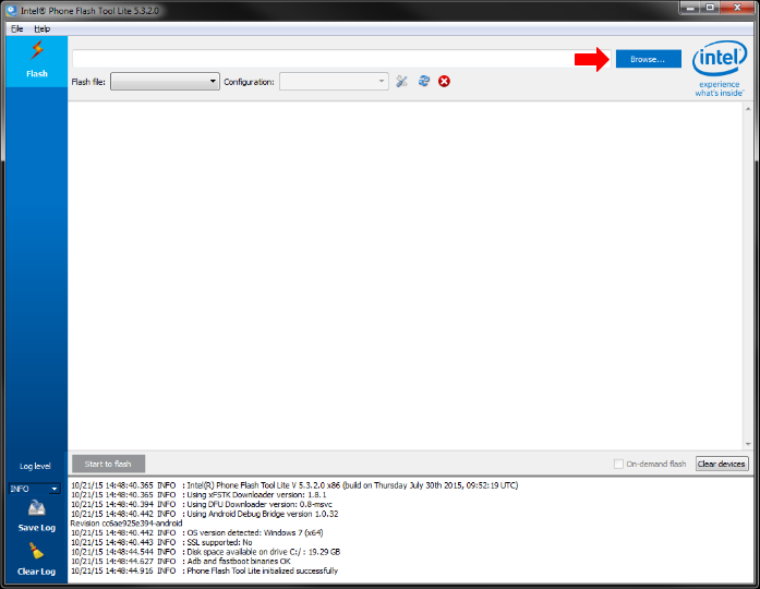]()
Click Browse, and navigate to the unzipped Edison firmware directory. Locate the FlashEdison.json file, and click Open. This will load the firmware into the Phone Flash Tool.
[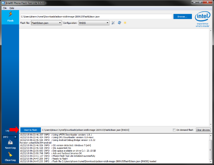]()
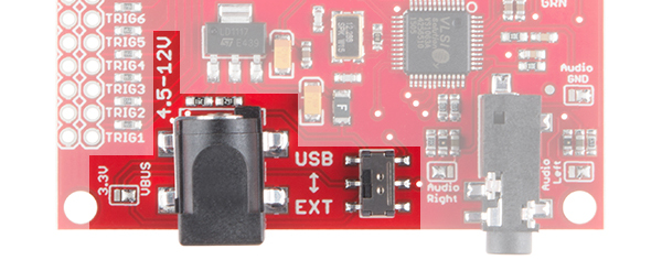
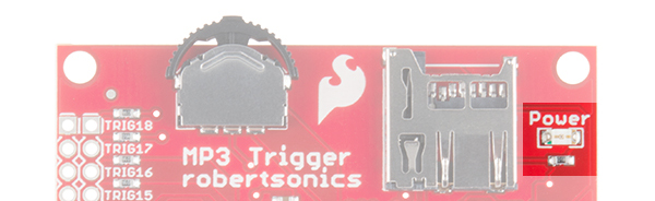
Click the Start to flash button. The Phone Flash Tool will tell you to plug in your Edison. Plug the USB micro cable into the OTG Port on the Base Block, and plug the other end into an open USB port of your computer.
![Edison Base Block OTG USB port]()
The Phone Flash Tool should begin to flash the Edison with a new firmware image.
![Flashing the Edison's firmware]()
The updating process can take anywhere from 5-10 minutes. We recommend
making a sandwich and catching up on web comics in that time. The Edison will restart once or twice after the installation is complete. Wait at least
2 more minutes after the update to allow the Edison to finish rebooting. Do not unplug the Edison in that time!
That’s it! You should see a “Flash success” message in the Phone Flash Tool. If this worked, you can close the Phone Flash Tool Lite, and move on to the next section.
![Successful firmware update in the Edison]()
NOTE: If the Edison failed to flash, try the process again from the beginning. Close the Flash Tool Lite and unplug the Edison. Start the Flash Tool Lite again. This might take a few tries. If that still does not work, try the
Manual Firmware Update method.
Using the XDK
If you have used other Integrated Development Environments before, the Intel® XDK IoT Edition might look familiar. If not, no worries! We will walk you through how to use the XDK (don’t worry, it’s not very complicated). If you would like to take a look at Intel’s official documentation on the XDK, it can be found here:
Intel® XDK IoT Edition Guide
Starting the XDK for the First Time
Start the Intel® XDK IoT Edition program, and you should be presented with a login screen.
![XDK login or account creation screen]()
Click Sign Up if you do not already have an Intel Developer Zone Account, and follow the on-screen instructions to create a new account. You will need to accept another Terms and Conditions statement.
The Welcome Screen
Once you have created an account (or not), you will be presented with the welcome screen. In this screen, you can choose an existing project to work on or create a new one.
![XDK welcome screen annotated]()
Click the image above for a larger view.
Creating a Project
To familiarize ourselves with the XDK IDE, we will create a blank project. Click on Templates under the Internet of Things Embedded Application tab. You will see a number of different templates appear that will help you get started with your IoT program. Select the Blank Template.
![Selecting a template in the XDK]()
Click Continue, and you will be presented with a pop-up window to name your project. You can name it anything you want, as we are just using it to explore the IDE right now. To keep all my XDK projects together, I like to use the prefix “XDK_”. I will use “XDK_Blank” for this example.
![Creating a new project in the XDK]()
Click Create. The project screen will greet you with a mostly empty JavaScript file.
NOTE: You might be asked to take a quick tour of the XDK when you first create a project. Feel free to do it or skip it.
The Project Screen
![XDK project screen annotated]()
We use the XDK to write code. There are several tools available that help us do that: code examples, syntax completion, a debugging interface, and so on. Once we have finished writing code, we click the Upload button to send that code to the Edison. The Run button then tells the Edison to run the code we just sent to it.
By default, the Yocto image on the Edison contains an “XDK Daemon.” A daemon is a computer program that runs in the background (at least according to Wikipedia). The XDK Daemon begins running as soon as the Edison boots and listens for a connection from a host computer (i.e. one running the XDK IoT Edition). It knows how to receive and store new code, and it will accept commands from the host computer to run, stop, and debug that program.
NOTE: You can click the word PROJECTS at the top-left of the window to return to the navigation screen.
Connecting to WiFi
We will want connect our Edison to a local WiFi network if we want to program it using the XDK or complete some of the experiments that require Internet access.
NOTE: Alternatively, you can use a USB Network to program the Edison from the XDK. Refer to
Appendix C to see how to use a USB network with your Edison. Note that without a WiFi connection, you will not be able to complete the exercises that require Internet access.
Connecting Over Serial
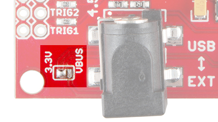
Unplug the USB cable from the OTG port on the Base Block, and plug it into Console port.
![Edison Base Block Console USB port]()
If it is not already open, start the XDK, and create a blank project (like we did in Using the XDK). Click on the Serial Terminal tab.
![Serial terminal in XDK]()
At the very bottom, click the drop-down list for Port and select the Edison device. This will change depending on the operating system. For example, it might be /dev/tty.usbserial-A402IXA0 in OS X, /dev/ttyUSB0 in Linux, or COM78 in Windows. Note that in Windows, you want COMxx[FTDI], not the Standard Serial Port option.
![Selecting a serial terminal in XDK]()
Make sure that the Baud Rate is 115200, Data Bits is 8, Stop Bits is 1, and Parity is “none.” Click Connect, and you should see the Edison’s terminal login appear.
![Connecting to Edison's serial terminal with the XDK]()
Getting on the Internet
Click in the Serial Terminal window and log in to the Edison:
Username: root
Hit ‘enter’ (there is no password). You should be presented with a root command prompt.
![Logging in as root]()
Enter configure_edison --setup. You will be walked through a series of steps. The first will ask you to create a password.
![Configure the Edison]()
We definitely recommend you set a password! It can be anything you want, so long as you can remember it. If you don’t set a password, evil hackers might be able to control your lights from their car. Or read your emails. That would be bad.
Press ‘enter’ and enter your password again. On the next screen, you will be asked to rename the Edison. You can give it a unique name or just press ‘enter’ to keep the default name. I shall call mine squishy.
![My Edison called squishy]()
The Edison will ask you to confirm the name. Type ‘y’ and press ‘enter’. You will then be asked to set up WiFi. Enter ‘y’ again.
![Yes, we want to set up WiFi on the Edison]()
Wait while the Edison scans for networks. You will then be presented with a list of available networks.
![Available WiFi access points]()
Type the number of the network you would like to join and press ‘enter’. Enter ‘y’ to accept the network, and enter the password for that network.
![Enter the password for the WiFi network]()
The Edison should automatically connect to the network. Enter ping 8.8.8.8 to try pinging one of Google’s Public DNS servers.
![Successful pings from the Edison]()
You should see a few responses in the form of “bytes received from 8.8.8.8.” Press ‘ctrl+c’ to stop the pinging. You can get the IP address of the Edison by entering ifconfig.
![Edison ifconfig]()
Under the wlan0 entry, make a note of the inet addr. In my case, it is 10.8.0.171. You can use this to connect to your Edison manually from the IoT Device drop-down menu if, for example, the Bonjour service is not running (if you ran the Installer and accepted all the defaults, Bonjour should have been installed).
NOTE: If you restart your Edison, it should auto-connect to the last network you set. However, you might not get the same IP address. We recommend connecting over serial and typing
ifconfig to see that address if you need it. You can also give your Edison a static IP address, if you so desire. See
here to lear more about networking in Linux.
Experiment 1: Hello, World!
Introduction
We realize that starting with “Hello, World!” is a cliché in the programming world, but it really is the perfect starting place with the XDK and Edison. We spent quite some time installing the XDK, flashing new firmware, and configuring the Edison. We can test all these things with one line of code!
Parts Needed
You will need the Edison and Block stack that we constructed in Building the Block Stack section.
Suggested Reading
- JavaScript Syntax– Whether you are new to JavaScript or a seasoned developer, you might want to look at how JavaScript statements are structured. For example, JavaScript uses semicolons.
- Oject-Oriented Programming (OOP)– JavaScript relies on objects to get work done. Reading about the history of OOP might be enlightening and entertaining.
Concepts
A Very Light Introduction to Objects
In JavaScript almost everything is an object. What is an object? In the real world, an object is just another word for a thing. A dog, for example, is a type of object.
![A dog object]()
A dog has properties, such as a breed, a fur color, a name, and so on. Dogs can also do things, like bark, sleep, play, etc.
OK, so how does this translate to the programming world? In most object-oriented languages, an object is a collection of data (bytes stored somewhere on the computer) that has been grouped together and wrapped up in a way that makes for easy access. If we wanted to make a JavaScript version of our dog, we might write something like:
language:javascript
var dog = {
    name: "Roland",
    color: "fawn",
    bark: function() {
        console.log("woof");
    }
};
In this example, we created a variable (as noted by the keyword var) called dog. A variable is a way to store things. In this case, we are storing our object (a collection of properties) in a storage container called dog.
All of the properties for this object are defined between the outside set of curly braces {}. We create a property called name and assign it the value "Roland". If we wanted to get the name of our dog object, we could access that property with:
language:javascript
dog.name;
Calling dog.name results in “Roland”.
In addition to our name and color properties, we also defined a function as a property. If we called
language:javascript
dog.bark();
the dog would do something. Functions are actions! They cause the object to do something. The parentheses () after dog.bark let us know that it is a function. They can also be used to pass parameters to the function, which we will see in a minute. Because bark() is a function inside an object, it is known as a method (functions not part of objects are just called functions).
If we dig into the bark() method, we see that it contains console.log("woof");. console is a special object that is known by most implementations of JavaScript (i.e. it is an object that always exists when we run the program). .log() is a method of the console object. By calling console.log() we can print something to the screen (assuming we have access to some kind of text output console).
"woof" is a parameter, which is a value that is passed to a function. In this case, “woof” is a string (as noted by the double quotes), which is a collection of characters. The function then, ideally, uses that value in its own code. In this case, console.log("woof") prints the word woof to the screen.
Ultimately, calling dog.bark(); prints woof to the screen.
This might be a lot to take in, but never fear! We will revisit these concepts over the course of these experiments. For now, know that objects are containers for properties and methods. We will be using the special console object to output text to the screen.
Hardware Hookup
We won’t need any new hardware. Just connect the USB cable from your computer to the Console Port on the stack you made in Building the Block Stack.
![Edison Base Block USB Console port]()
The Code
Open the XDK, and create a new project. Use the Blank Template, and give it an appropriate name (we’ll call this one “XDK_Hello”). If you need a refresher on creating projects, see Using the XDK.
NOTE: The Edison is remotely programmable, but your host computer must be on the same network (
subnet) as the Edison if you want to use the XDK (i.e. both your computer and Edison are connected to the same WiFi network). Alternatively, you can use a USB cable to create a
USB network between your computer and the Edison.
The first thing we want to do is connect to our Edison. To do that, click the drop-down list by IoT Device, and select your Edison device.
![Select Edison device]()
NOTE: If the Edison device does not appear automatically (e.g. you don't have Bonjour installed), then you can select
Add Manual Connection and fill in the IP address of the Edison you got from
Connecting to WiFi.
You should be presented with a connection screen. Type in the password you set for the Edison in the Password field.
![IoT Device connection screen]()
Click Connect. If you get presented with a message claiming that the “Intel XDK Daemon is old” or that you need to sync clocks with the Edison, choose to Update the Dameon or Sync as appropriate and follow the prompts.
![What do you mean my XDK daemon is old?]()
Once you have updated, synced, and connected, you should see a message in the console of the Intel XDK IoT tab.
![XDK connected to Edison]()
In main.js, add the following line:
language:javascript
console.log("Hello, World!");
Find and click the Upload button.
![Upload code to the Edison]()
If you are presented with a message exclaiming that you have “Modified Project Files,” click Save and Proceed.
In the console, you should see the message “Upload Complete.” Press the Run button.
![Run code on the Edison]()
What You Should See
The phrase “Hello, World!” should appear in the console.
![Edison Hello World]()
If you see this, feel free to celebrate. We’ll wait a moment while you do that.
Why is this simple phrase monumental? Well, it means all our preparing and configuring worked! We wrote a simple program, sent it to the Edison, and had the Edison run it. Cool.
Code to Note
The Console Object
console is a special object that has been pre-defined elsewhere in our JavaScript environment. It outputs to standard output, which is a text display device (real or virtual) for most computer systems.
The Edison relies on Node.js to run JavaScript programs. More information about the console object can be found in the official documentation.
Methods
We mentioned methods briefly in our introduction to objects. In this exercise, we used the .log() method, which takes input in the form of a string (a parameter) and displays it on a new line in the console. The Node.js documentation contains a section on .log().
Comments
There are different ways to make comments in your code. Comments are a great way to quickly describe what is happening in your code.
// This is a comment - anything on a line after "//" is ignored by the computer.
/* This is also a comment - this one can be multi-line, but it
must start and end with these characters */
Troubleshooting
- The Edison won’t connect– This is possible if the Edison is not powered or configured properly. See the “Edison won’t connect” section in the Appendix A: Troubleshooting.
- Code will not upload– Make sure the Edison is on the same network as your computer and you have selected your Edison from the IoT Device drop-down menu in the XDK.
- Nothing prints on the console– Make sure that the Edison is connected. Additionally, if you see any errors on the console, read them carefully, as they will often tell where to look in your code (for example, you might have forgotten the quotation marks around “Hello, World!”).
- Nothing works!– Don’t worry! We have an awesome tech support staff to help you out if there is something wrong. Please contact our tech support team.
Going Further
Now that you see how to connect your Edison to the XDK, upload code, and run a program, we will move on to more advanced topics including connecting other pieces of hardware to the Edison Block stack. After each experiment, we will give you a few challenges to try on your own as well as some suggested reading.
Challenges
- Remember the description of the dog object in the beginning of this chapter? Copy the definition of the dog object (the snippet of JavaScript code) into the XDK. Write some code that has the dog bark (e.g. you will see woof appear in the console). Hint: you will need to use
console.log(). - Using the same dog object example, print out the dog’s name and color to the console.
Digging Deeper
Introduction
In the previous exercise, we tested the connection to the Edison and showed that we could upload code. Now, we can move on to more interesting circuits and examples. In this section, we introduce the humble push button. We connect it to one of the Edison’s general-purpose input/output (GPIO) pins and write some code that does something whenever the button is pushed.
This experiment has 2 parts. Both parts use the same hardware, but each has its own code. We recommend you try them both to get an understanding of the different ways to use button pushes.
Parts Needed
In addition to the Edison and Block Stack, you will need the following parts:
- 1x Breadboard
- 1x Push Button
- 1x 1kΩ Resistor
- 4x Jumper Wires
![1k resistor]()
The 1kΩ resistor has the color bands brown, black, red, gold
Using the Edison by itself or don't have the kit? No worries! You can still have fun and follow along with this experiment. We suggest using the parts below:
In stock
COM-10969
Resistors are a good thing, in fact, they're actually crucial in a lot of circuit designs. The only problem seems to be that …
65In stock
DEV-13045
The Intel® Edison is an ultra small computing platform that will change the way you look at embedded electronics. Each Ediso…
9In stock
PRT-12002
This is your tried and true white solderless breadboard. It has 2 power buses, 10 columns, and 30 rows - a total of 400 tie i…
17In stock
PRT-00116
A row of headers - break to fit. 40 pins that can be cut to any size. Used with custom PCBs or general custom headers.
**Fea…
18In stock
PRT-11026
If you need to knock up a quick prototype there's nothing like having a pile of jumper wires to speed things up, and let's fa…
18In stock
PRT-00115
Single row of 40-holes, female header. Can be cut to size with a pair of wire-cutters. Standard .1" spacing. We use them exte…
5In stock
DEV-13038
The Intel® Edison is an ultra small computing platform that will change the way you look at embedded electronics. Each Ediso…
3In stock
DEV-13024
The Intel® Edison is an ultra small computing platform that will change the way you look at embedded electronics. Each Ediso…
15In stock
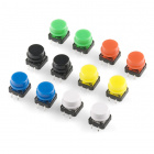
COM-10302
These tactile buttons are great for all sorts of projects. This assortment comes with 2 of each of 6 different colors for a t…
Suggested Reading
Concepts
Functions
We mentioned briefly in the last section that functions are pieces of code that do things. To make this more clear, a function is a block of code created to perform a particular task. Functions are useful because they can be written once and called many, many times from other parts of code (we call this code reuse).
In our two code examples below, we will write our own functions and then call them. In JavaScript, functions looks like this:
language:JavaScript
function doSomething( /* parameters */ ) {
    /* Things happen here */
}
We know it is a function because we used the function keyword. Thanks for making this explicit, JavaScript. We can also have 0 to any number of parameters in our function. Parameters are variables that are used to store pieces of information passed to the function. For example:
language:JavaScript
function saySomething(thing) {
    console.log(thing);
}

saySomething("Hi");
We first created a function that outputs something to the console. In this case, the function accepts the parameter thing, which becomes a variable. We can access the contents of that variable by writing thing.
Then, we call our function by writing saySomething(). In between the parentheses, we wrote the string "Hi". This string is passed to the saySomething() function as a parameter and assigned to the variable thing. We then print the contents of thing (“Hi” in this example) to the console.
If we wanted to print something else, we could write saySomething("Something else");. And that’s a simple form of code reuse!
Libraries
![A particularly grand library]()
OK, not THAT kind of library
Libraries are pieces of code that have been packaged up for easy reuse. Often, they are written by someone else (or a group of people).
Node.js (the runtime environment that runs our code on the Edison) uses modules, which are very similar to libraries. Modules are just other pieces of code that we can reuse in our code. In these experiments, we rely heavily on MRAA, which is a library (and subsequent Node.js module) created by Intel and allows us to easily communicate with the hardware pins on the Edison.
We can import the MRAA module with the line
language:JavaScript
var mraa = require('mraa');
With that, all the objects, variables, and functions in the MRAA module are loaded into the variable mraa. We can access those objects, variables, and functions by calling mraa. For example, mraa.Gpio() creates a new GPIO pin that we can access.
The Pull-Up Resistor
We can use a resistor to set a default state of a pin on a microcontroller (or, in this case, the Edison). The pull-up resistor, specifically, sets the state of the pin to a voltage (VCC in the diagram below). For our circuit, we will be using 3.3V as the high voltage. Low will be ground (GND or 0V).
![Example of a pull-up resistor]()
When the switch (or button) is open (as in the diagram), the input pin is VCC. Because little or no current flows through R1, the voltage at the pin is the same (or very nearly the same) as VCC. We will say that the pin is in the “high state” or “logic ‘1’”.
When the switch (or button) is closed, the input pin is the same voltage as GND (0V). The switch creates a short circuit to GND, which causes some current to flow from VCC, through R1, to GND. However, because of the short circuit, the input pin has the same voltage as GND. We will say that the pin is in the “low state” or “logic ‘0’”.
Hardware Hookup
Your kit comes with a bunch of different color push button. All push buttons behave the same, so go ahead and use your favorite color! Follow the Fritzing diagram below.
NOTE: We are using GP14 on the GPIO Block, which connects to GPIO pin 14 on the Edison's 70-pin Hirose connector (see
here for the pinout). However, the MRAA library uses a different numbering scheme. GP14 is actually pin 36 according to MRAA. The GPIO pin to MRAA pin mapping can be found in
Appendix E: MRAA Pin Table. Find the GPIO number you are using on the left-most column and lookup the MRAA number on the next column. The MRAA number is what you will use in software.
Fritzing Diagram
![Edison SIK button Fritzing]()
Having a hard time seeing the circuit? Click on the Fritzing diagram to see a bigger image.
Tips
The leads across each other on the push buttons are always connected to each other. The leads on the same side are only connected when button is pressed.
![Push button connections]()
Part 1: Polling
The Code
language:JavaScript
/*jslint node:true, vars:true, bitwise:true, unparam:true */
/*jshint unused:true */
// Leave the above lines for propper jshinting

/**
 * SparkFun Inventor's Kit for Edison
 * Experiment 2 - Part 1: Pushing Some Buttons
 * This sketch was written by SparkFun Electronics
 * October 27, 2015
 * https://github.com/sparkfun/Inventors_Kit_For_Edison_Experiments
 *
 * This is a simple example program that displays the state of a button
 * to the console.
 *
 * Released under the MIT License(http://opensource.org/licenses/MIT)
 */

// Import the MRAA module
var mraa = require('mraa');

// Set up a digital input/output on MRAA pin 36 (GP14)
var buttonPin = new mraa.Gpio(36);

// Set that pin as a digital input (read)
buttonPin.dir(mraa.DIR_IN);

// Call the periodicActivity function
periodicActivity();

// This function is called forever (due to the setTimeout() function)
function periodicActivity() {

    // Read the value of the pin and print it to the screen
    var val = buttonPin.read();
    console.log('Button is ' + val);

    // Wait for 250 ms and call this function again
    setTimeout(periodicActivity, 250);
}
What You Should See
Try pushing the button.
![Button connected to the Edison]()
The console should start outputting “Button is 1”, which means that the pin connected to the button is currently in the high state (3.3V, logic ‘1’). When you push the button (hold it down for a second), the console should show “Button is 0”, which means that the pin is in the low state (0V, logic ‘0’).
![Polling button output]()
Code to Note
In JavaScript, functions are objects. Say what? I know it is weird to think about, but they are. The good news is that we can pass functions (like objects) as parameters to other functions. For example, we pass periodicActivity (a function) to setTimeout (another function), which causes periodicActivity to be called every 250 ms (in this example).
Additionally, note that we told MRAA that we want to use pin 36. Pin 36 is defined by MRAA and mapped to GP14, which is the pin definition according to the Edison hardware. Knowing which MRAA pin maps with which GP pin can be confusing, so we crated a nice table in Appendix E. The Edison pinout can be found here.
Part 2: Interrupt Service Routine
The Code
language:JavaScript
/*jslint node:true, vars:true, bitwise:true, unparam:true */
/*jshint unused:true */
// Leave the above lines for propper jshinting

/**
 * SparkFun Inventor's Kit for Edison
 * Experiment 2 - Part 2: Interrupt Service Routine
 * This sketch was written by SparkFun Electronics
 * October 27, 2015
 * https://github.com/sparkfun/Inventors_Kit_For_Edison_Experiments
 *
 * This is a simple example program that prints an incrementing number
 * to the console every time a button is pushed.
 *
 * Released under the MIT License(http://opensource.org/licenses/MIT)
 */

// Import the MRAA module
var mraa = require('mraa');

// Set up digital input on MRAA pin 36 (GP14)
var buttonPin = new mraa.Gpio(36);
buttonPin.dir(mraa.DIR_IN);

// Global counter
var num = 0;

// Our interrupt service routine
function serviceRoutine() {
    num++;
    console.log("BOOP " + num);
}

// Assign the ISR function to the button push
buttonPin.isr(mraa.EDGE_FALLING, serviceRoutine);

// Do nothing while we wait for the ISR
periodicActivity();
function periodicActivity() {
    setTimeout(periodicActivity, 1000);
}
What You Should See
You should not see anything when you first run the program. Press the button, and the word “BOOP” should appear along with a number. Press the button again, and that number should increment by 1.
![Boop]()
Code to Note
Interrupt service routines (ISRs) are important in the world of embedded electronics. It is very similar to JavaScript’s notion of event-driven programming. When a user or some other external force performs an action, the program responds. In this case, whenever a button was pushed, the serviceRoutine() function gets called.
As in the previous polling example, we use a function as a parameter. We pass the function serviceRoutine to the buttonPin.isr() function. We use mraa.EDGE_FALLING to declare that serviceRoutine should be called whenever the pin’s voltage goes from high (3.3V) to low (0V).
Troubleshooting
- The Edison won’t connect– This is possible if the Edison is not powered or configured properly. See the “Edison won’t connect” section in the Appendix A: Troubleshooting.
- Nothing happens when the button is pushed– Double-check the wiring. Often, a jumper wire is off by 1 hole!
Going Further
Challenges
- Add a second button so that when the first button is pushed, it prints “BOOP” to the console, and when the second button is pushed, it prints “BEEP” to the console.
- You might have noticed that pushing the button on the second example causes more than one “BOOP” to appear (if not, try pushing the button many times to see if you can get more than one “BOOP” to appear per button push). This is a phenomenon known as bouncing. Modify the Part 2 example to prevent this from happening (known as debouncing).
Digging Deeper
Experiment 3: Blinky
Introduction
Often, blinking an LED is the first step in testing or learning a new microcontroller: a veritable “Hello, World!” of embedded electronics. However, the GPIO Block requires that we introduce a new component, the transistor, into the mix. As a result, we saved the blinky example for the third experiment.
We will connect an LED to the Edison (using the GPIO Block and a transistor). With some JavaScript, we can control that LED by turning it on and off.
Parts Needed
In addition to the Edison and Block Stack, you will need the following parts:
- 1x Breadboard
- 1x RGB LED
- 1x NPN Transistor
- 1x 1kΩ Resistor
- 1x 100Ω Resistor
- 5x Jumper Wires
![100 Ohm resistor]()
The 100Ω resistor has the color bands brown, black, brown, gold
![1k resistor]()
The 1kΩ resistor has the color bands brown, black, red, gold
Using the Edison by itself or don't have the kit? No worries! You can still have fun and follow along with this experiment. We suggest using the parts below:
In stock
COM-10969
Resistors are a good thing, in fact, they're actually crucial in a lot of circuit designs. The only problem seems to be that …
65In stock
DEV-13045
The Intel® Edison is an ultra small computing platform that will change the way you look at embedded electronics. Each Ediso…
9In stock
PRT-12002
This is your tried and true white solderless breadboard. It has 2 power buses, 10 columns, and 30 rows - a total of 400 tie i…
17In stock
PRT-00116
A row of headers - break to fit. 40 pins that can be cut to any size. Used with custom PCBs or general custom headers.
**Fea…
18In stock
PRT-11026
If you need to knock up a quick prototype there's nothing like having a pile of jumper wires to speed things up, and let's fa…
18In stock
PRT-00115
Single row of 40-holes, female header. Can be cut to size with a pair of wire-cutters. Standard .1" spacing. We use them exte…
5In stock
DEV-13038
The Intel® Edison is an ultra small computing platform that will change the way you look at embedded electronics. Each Ediso…
3In stock
DEV-13024
The Intel® Edison is an ultra small computing platform that will change the way you look at embedded electronics. Each Ediso…
15In stock
COM-09264
Ever hear of a thing called RGB? Red, Green, Blue? How about an RGB LED? These 5mm units have four pins - Cathode is the long…
2In stock
COM-00521
These are very common, high quality BJT NPN transistors made by ST Micro.
**Datasheet: **[2N3904](http://www.sparkfun.com/da…
Suggested Reading
Concepts
The Transistor
The GPIO Block is not capable of sourcing more than a few milliamps, which is not enough to fully light up an LED. To do that, we will use a transistor. A transistor is a device that can be used to amplify or switch electrical current. We will be using a bipolar junction transistor (BJT), which allows current to flow through the collector and emitter pins whenever a (much smaller) current flows into the base pin.
In this experiment, we will connect the base of the BJT to GP12 on the GPIO Block. When the GP12 pin goes high (3.3V), this causes a little bit of current to flow from GP12 through the base, which turns the transistor on. This allows current to flow from the 3.3V supply (also on the GPIO Block), through the collector, and out the emitter. This current then flows through the 100Ω resistor and LED, turning the LED on.
![Transistor switch for LED]()
We can calculate the amount of current flowing through the LED, as we want to make sure it is not over 20mA, as per the RGB LED datasheet. To do that, we need to figure out what the voltage drop across the 100Ω resistor. Starting with 3.3V, we can determine that the voltage across the collector and emitter (Vce) is 0.2V (Vce(sat) in the datasheet) when the transistor is fully on. Again from the LED’s datasheet, we see that that typical drop across the red LED is 2V. As a result, the voltage drop across the resistor can be calculated:
![Calculating the voltage drop across the resistor]()
Knowing that the drop across the resistor is 1.1V, we can use Ohm’s Law (V = I x R) to calculate the current flowing through the resistor:
![Finding the current through the resistor]()
![Current through limiting resistor]()
How to Use Logic Like a Vulcan
One of the things that makes the Edison so useful is that it can make complex decisions based on the input it’s getting. For example, you could make a thermostat that turns on a heater if it gets too cold, or a fan if it gets too hot, and it could even water your plants if they get too dry. In order to make such decisions, JavaScript provides a set of logic operations that let you build complex “if” statements. They include:
| == | EQUIVALENCE | A == B is true if A and B are the SAME. |
|---|
| != | DIFFERENCE | A != B is true if A and B are NOT THE SAME. |
|---|
| && | AND | A && B is true if BOTH A and B are TRUE. |
|---|
| || | OR | A || B is true if A or B or BOTH are TRUE. |
|---|
| ! | NOT | !A is TRUE if A is FALSE.!A is FALSE if A is TRUE. |
|---|
You can combine these functions to build complex if() statements. For example:
language:c

if ((mode == heat) && ((temperature < threshold) || (override == true))) {
    turnOnHeater();
}
…will turn on a heater if you’re in heating mode AND the temperature is low, OR if you turn on a manual override. Using these logic operators, you can program your Edison to make intelligent decisions and take control of the world around it!
In addition to the comparator ‘==’ and ‘!=’, JavaScript also has the strict comparators ‘===’ and ‘!==’ where the two values being compared need to be the same type (e.g. both a string). See this page to learn more about JavaScript comparators.
Hardware Hookup
Fritzing Diagram
![Red LED with Edison Fritzing]()
Having a hard time seeing the circuit? Click on the Fritzing diagram to see a bigger image.
Tips
RGB LED
You can use a set of needle nose pliers to bend the LED’s leads and a pair of cutters to fit the LED in the breadboard. Note that there is a flat side on the plastic ring around the bottom of the LED. This denotes the side with the pin that controls the red color. See this tutorial to learn more about polarity.
![Common cathode RGB LED]()
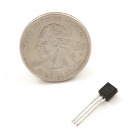
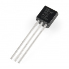
NPN Transistor
WARNING: The 2N3904 transistor and TMP36 temperature sensor look very similar! Examine the flat face of the
TO-92 packages very carefully and find one that says
2N 3904.
Note that the flat face with the ‘N’ of the transistor in the Fritzing diagram matches up with the flat face (with the writing) of the physical part. With the flat edge facing you, the pins are as follows:
![Annotated 2N3904 NPN transistor]()
The Code
language:JavaScript
/*jslint node:true, vars:true, bitwise:true, unparam:true */
/*jshint unused:true */
// Leave the above lines for propper jshinting

/**
 * SparkFun Inventor's Kit for Edison
 * Experiment 3: Blinky
 * This sketch was written by SparkFun Electronics
 * October 29, 2015
 * https://github.com/sparkfun/Inventors_Kit_For_Edison_Experiments
 *
 * Blink an LED connected to GP12 (need a transistor if using the Base Block).
 *
 * Released under the MIT License(http://opensource.org/licenses/MIT)
 */

// Import the MRAA module
var mraa = require('mraa');

// Set up a digital output on MRAA pin 20 (GP12)
var ledPin = new mraa.Gpio(20);
ledPin.dir(mraa.DIR_OUT);

// Global variable to remember the LED state
var led = 0;

// Call this function over and over again
periodicActivity();
function periodicActivity() //
{
    // Switch state of LED
    if (led === 0) {
        led = 1;
    } else {
        led = 0;
    }

    // Turn the LED on
    ledPin.write(led);

    // Wait for 500 ms and call this function again
    setTimeout(periodicActivity, 500);
}
What You Should See
Upload and run the program. The LED should start flashing red.
![Edison flashing an LED]()
Code to Note
After we declare the ledPin as an output with mraa.DIR_OUT, we create the variable led that stores the state of the led (‘1’ for on and ‘0’ for off). Because this variable (and similarly mraa and ledPin) is declared outside of any object or function, they are considered global variables, which means they can be accessed by any function, object, etc. in the entire program. In most programming circles, using global variables is considered very bad practice. However, we rely on them in most of our examples because:
- JavaScript makes creating and accessing global variables very easy. This is not a legitimate excuse, but it does make the examples easier to follow.
- Most of the examples are simple, 1-file programs where we can keep track of all the global variables. Global variables are still used by embedded programmers, as most embedded programs are relatively small and they allow for different types of CPU, RAM, or storage optimization.
Troubleshooting
- The Edison won’t connect– This is possible if the Edison is not powered or configured properly. See the “Edison won’t connect” section in the Appendix A: Troubleshooting.
- The LED doesn’t flash– Once again, check the wiring. Make sure you are connecting the base of the transistor to GP12 (through a 1kΩ resistor). Additionally, you can add some
console.log() statements in the code to see if certain parts are being executed.
Going Further
Challenges
- Make the LED turn on for 1 second and off for 1 second.
- Make the LED turn on for 200 ms and off for 1 second.
- Add a button (like in the previous experiment). Create a program such that the LED turns on only when the button is pushed.
Digging Deeper
Experiment 4: Email Notifier
Introduction
While flashing an LED is not the most interesting activity, we could use the LED as a way to notify us if something is happening. For example, we could turn on an LED if we have a new email. That way, we would know that we needed to check our inbox!
To do this, we will have the Edison log in to an email account, read the number of unread emails, and turn on an LED if it is over 0.
NOTE: This example shows how to connect to
Gmail and
Yahoo mail servers. If you are not using one of those, you still might be able to connect (see
here for a list of IMAP servers), but only Gmail and Yahoo have been tested. Also, you will need to enter your username and password as plain text into the code. It's a fun project, but you don't have to do it if you are not comfortable with that!
Parts Needed
We’ll be using the same circuit as in the previous example, so you don’t need to build anything new! In addition to the Edison and Block Stack, you will need the following parts:
- 1x Breadboard
- 1x RGB LED
- 1x NPN Transistor
- 1x 1kΩ Resistor
- 1x 100Ω Resistor
- 5x Jumper Wires
Using the Edison by itself or don't have the kit? No worries! You can still have fun and follow along with this experiment. We suggest using the parts below:
In stock
COM-10969
Resistors are a good thing, in fact, they're actually crucial in a lot of circuit designs. The only problem seems to be that …
65In stock
DEV-13045
The Intel® Edison is an ultra small computing platform that will change the way you look at embedded electronics. Each Ediso…
9In stock
PRT-12002
This is your tried and true white solderless breadboard. It has 2 power buses, 10 columns, and 30 rows - a total of 400 tie i…
17In stock
PRT-00116
A row of headers - break to fit. 40 pins that can be cut to any size. Used with custom PCBs or general custom headers.
**Fea…
18In stock
PRT-11026
If you need to knock up a quick prototype there's nothing like having a pile of jumper wires to speed things up, and let's fa…
18In stock
PRT-00115
Single row of 40-holes, female header. Can be cut to size with a pair of wire-cutters. Standard .1" spacing. We use them exte…
5In stock
DEV-13038
The Intel® Edison is an ultra small computing platform that will change the way you look at embedded electronics. Each Ediso…
3In stock
DEV-13024
The Intel® Edison is an ultra small computing platform that will change the way you look at embedded electronics. Each Ediso…
15In stock
COM-09264
Ever hear of a thing called RGB? Red, Green, Blue? How about an RGB LED? These 5mm units have four pins - Cathode is the long…
2In stock
COM-00521
These are very common, high quality BJT NPN transistors made by ST Micro.
**Datasheet: **[2N3904](http://www.sparkfun.com/da…
Suggested Reading
Concepts
External Modules
In the previous few examples, we have been relying on the MRAA module to control various hardware from the Edison. MRAA comes pre-installed on the Edison, so we did not have to perform any extra steps to install it. However, in this example, we will use node-imap, which contains several useful functions for connecting to Internet Message Access Protocol (IMAP) servers and retrieving email.
If we were to log in to the Edison via SSH or serial terminal, we could install Node.js packages (e.g. modules) using the npm command (e.g. npm install imap). However, with the XDK, we can tell the IDE to install necessary modules automatically whenever we upload code. This is accomplished by adding the library name to a list of dependencies in the project. The specifics on how to do this can be found in “The Code” section.
Callbacks
![MicroTAC Elite VIP cellular phone]()
I wonder if caller ID was a feature
A callback is a piece of code (often a function) that is expected to be called by another piece of code at a convenient time. A popular way to use callbacks in web programming is to assign a function to a mouse click event. For example:
language:JavaScript
element.on('click', myFunction);

myFunction() {
    console.log("Hi!");
}
Whenever a user clicks on the web page element (called element in this example), myFunction() gets called. In this instance, myFunction() is the callback, and our assignment, element.on('click', myFunction);, is known as creating an event handler. See here to learn more about the .on() event handler.
Hardware Hookup
The circuit is the same as in the previous experiment.
![Red LED with Edison Fritzing]()
Having a hard time seeing the circuit? Click on the Fritzing diagram to see a bigger image.
The Code
Create a new project in the XDK. Click on package.json in the files browser on the left pane. Add the line
language:JavaScript"imap": "0.8.16"
under "dependencies". This will tell the XDK to download and install the node-imap v0.8.16 module before running the program.
![Adding a new library]()
NOTE: If you are using Gmail, you will need to go to the
account security settings page and turn
access for less secure apps to
ON. We recommend turning it off once you are done with this exercise (unless you want to keep a permanent email notifier!).
Copy the following code into main.js. If you are not using Gmail, you can comment out (or delete) the part labeled “Set email credentials (Gmail)”. If you are using Yahoo, you will want to uncomment the part labeled “Set email credentials (Yahoo)”.
Finally, change the <username> and <password> parts to your actual email username and password.
language:JavaScript
/*jslint node:true, vars:true, bitwise:true, unparam:true */
/*jshint unused:true */
// Leave the above lines for propper jshinting

/**
 * SparkFun Inventor's Kit for Edison
 * Experiment 4: Email Notifier
 * This sketch was written by SparkFun Electronics
 * October 29, 2015
 * https://github.com/sparkfun/Inventors_Kit_For_Edison_Experiments
 *
 * Connect to an email service and turn on an LED if there are any unread
 * emails.
 *
 * Released under the MIT License(http://opensource.org/licenses/MIT)
 */

// Import the MRAA and IMAP modules
var mraa = require('mraa');
var Imap = require('imap');

// Set up a digital output on MRAA pin 20 (GP12)
var ledPin = new mraa.Gpio(20);
ledPin.dir(mraa.DIR_OUT);

// It's usually a good idea to set the LED to an initial state
ledPin.write(0);

// Global LED variable to know if the LED should be on or off
var led = 0;

// Set email credentials (Gmail)
// Turn on "Acess for less secure apps" in Google account settings
// https://www.google.com/settings/security/lesssecureapps
var imap = new Imap({
  user: "<username>@gmail.com",
  password: "<password>",
  host: "imap.gmail.com",
  port: 993,
  tls: true
});

// Set email credentials (Yahoo)
/*var imap = new Imap({
  user: "<username>@yahoo.com",
  password: "<password>",
  host: "imap.mail.yahoo.com",
  port: 993,
  tls: true
});*/

// Open the mail box with the name "INBOX"
function openInbox(cb) {
  imap.openBox("INBOX", true, cb);
}

// This is called when a connection is successfully made to the IMAP server.
// In this case, we open the Inbox and look for all unread ("unseen")
// emails. If there are any unread emails, turn on a LED.
imap.on('ready', function() {
    openInbox(function(err, box) {
        if (err) throw err;

        // Search for unread emails in the Inbox
        imap.search(["UNSEEN"], function(err, results) {
            if (err) throw err;

            // Print the number of unread emails
            console.log("Unread emails: " + results.length);

            // If there are unread emails, turn on an LED
            if (results.length > 0) {
                ledPin.write(1);
            } else {
                ledPin.write(0);
            }

            // Close the connection
            imap.end();
        });
    });
});

// If we get an error (e.g. failed to connect), print that error
imap.on('error', function(err) {
    console.log(err);
});

// When we close the connection, print it to the console
imap.on('end', function() {
  console.log("Connection closed.");
});

// Call this function over and over again
periodicActivity();
function periodicActivity() //
{
    // Perform a quick connection to the IMAP server and look for unread emails
    imap.connect();

    // Wait for 10 seconds before checking for emails again
    setTimeout(periodicActivity, 10000);
}
What You Should See
When uploading the code, you might see some notifications that the XDK is downloading and installing npm packages. Just be patient while the packages are installed.
![XDK installing npm packages]()
When you run the code, it should connect to your email account and print to the console the number of unread emails every 10 seconds.
![Unread emails]()
I really should get in the habit of checking my emails more often
If you have one or more unread emails, the red LED should come on.
![Edison email notifier]()
Code to Note
Callbacks
I know that we talked about callbacks in the Concepts section, but now we get to see them in action. The node-imap package heavily relies on them, so it is important to get used to them if you plan to use that package in the future.
imap.on is used several times. This function gets called when something particular happens in our program. These are known as “Connection Events” according to the Application Program Interface (API) documentation. We can define particular connection events using strings.
For example, imap.on('ready', function() {...}); allows us to define a function (as noted by the function() keyword) that is called whenever a successful connection is made with the IMAP server.
imap.on('error', function() {...}); is called if there is a problem making a connection.
imap.on('end', function() {...}); is called whenever the connection with the server is closed.
There is another seemingly odd callback. In our imap.on('ready',...) code, we call openInbox(function(err, box) {...});. A few lines above, we define the openInbox() function, which tells the imap object to open our inbox and then call another function (as denoted by cb for “callback”). This callback function (cb) is the function we defined inside openInbox(function(err, box) {...});. So yes, we call a function that accepts another function as a parameter, which then calls that function as a callback. Don’t worry if this was confusing; it is a bit hard to follow. Knowing how to use the .on() callback functions is the most important part of this exercise.
Error Handling
Being able to appropriately deal with errors is a very useful ability in a program. The example relies on if (err) throw err; to determine if an error has occurred (e.g. could not connect to the IMAP server).
If we dig into the node-imap code, we would likely find a few catch statements. if (err) only executes the second part (throw err) if an err actually exists (not null or undefined). throw stops execution within that loop, function, etc., and program control is passed to the first catch statement it finds within the calling stack (e.g. look for a function that called the callback withing a try/catch statement).
If an error occurs, the node-imap module calls our callback function imap.on('error', function() {...});, which lets us handle the error. In this case, all we do is print the error to the console.
Troubleshooting
- It won’t connect to the IMAP server– This could be caused by several reasons:
- Make sure your Edison has Internet access
- Ensure you are using the correct IMAP server settings (Gmail and Yahoo examples are given in the code)
- Check that your email and password are correct in the code
- The LED won’t come on– As always, double-check the wiring. Make sure you are seeing
Unread emails: is appearing in the console, and that number is at least 1. Be patient, as it can take a few seconds for the program to make a connection to the IMAP server.
Going Further
Challenges
- Have the LED flash rapidly when there are unread emails.
- Have the LED turn on only when there are unread emails from a particular sender (e.g. a friend or your boss). You will need to carefully read the examples in the node-imap documentation.
- When you receive a new email, print its contents to the console and flash the LED. Hint: Take a look at the
mail(...) callback in Connection Events in the node-imap documentation.
Digging Deeper
Experiment 5: Web Page
Introduction
We know that we are exhausting this one LED circuit, but it really does prove useful in showing different features of the Edison. Hopefully, it spawns some cool project ideas for you! Just remember, if you can blink an LED, you can connect that output to any number of electrical devices. Relays, for example, are great for controlling more powerful components, like light bulbs, ceiling fans, and toasters. Additionally, going from an output (e.g. an LED) to an input (e.g. a button) is not too difficult.
Now that we have reached out to our email inbox to light an LED, why don’t we serve up a web page that allows us to control that LED? This experiment is divided into 2 parts. In the first section, we will create a basic web page that we can navigate to from any computer on the network. In the second section, we add a button to that page to allow control over an LED attached to the Edison.
Parts Needed
We’ll be using the same circuit as in the previous example, so you don’t need to build anything new! In addition to the Edison and Block Stack, you will need the following parts:
- 1x Breadboard
- 1x RGB LED
- 1x NPN Transistor
- 1x 1kΩ Resistor
- 1x 100Ω Resistor
- 5x Jumper Wires
Using the Edison by itself or don't have the kit? No worries! You can still have fun and follow along with this experiment. We suggest using the parts below:
In stock
COM-10969
Resistors are a good thing, in fact, they're actually crucial in a lot of circuit designs. The only problem seems to be that …
65In stock
DEV-13045
The Intel® Edison is an ultra small computing platform that will change the way you look at embedded electronics. Each Ediso…
9In stock
PRT-12002
This is your tried and true white solderless breadboard. It has 2 power buses, 10 columns, and 30 rows - a total of 400 tie i…
17In stock
PRT-00116
A row of headers - break to fit. 40 pins that can be cut to any size. Used with custom PCBs or general custom headers.
**Fea…
18In stock
PRT-11026
If you need to knock up a quick prototype there's nothing like having a pile of jumper wires to speed things up, and let's fa…
18In stock
PRT-00115
Single row of 40-holes, female header. Can be cut to size with a pair of wire-cutters. Standard .1" spacing. We use them exte…
5In stock
DEV-13038
The Intel® Edison is an ultra small computing platform that will change the way you look at embedded electronics. Each Ediso…
3In stock
DEV-13024
The Intel® Edison is an ultra small computing platform that will change the way you look at embedded electronics. Each Ediso…
15In stock
COM-09264
Ever hear of a thing called RGB? Red, Green, Blue? How about an RGB LED? These 5mm units have four pins - Cathode is the long…
2In stock
COM-00521
These are very common, high quality BJT NPN transistors made by ST Micro.
**Datasheet: **[2N3904](http://www.sparkfun.com/da…
Suggested Reading
- How Web Servers Work– A look at how information is served to your computer when you browse a web site
- Introduction to HTML– HyperText Markup Language (HTML) is a fairly old computer language still in use today to create web pages. We will be using some HTML to make our web page.
- WebSockets– We will use the socket.io module in the second part of this exercise to implement WebSockets. This will allow us to create a connection between the Edison and another computer so we can simple commands (like toggle an LED).
Concepts
Browsing to a Web Page
![Connected computers and the Internet]()
It’s like a series of tubes!
In simplest terms, when you “browse to a web page,” your computer makes a request to a remote server somewhere on the Internet. The actual server (physical computer) you are accessing can be anywhere in the world (assuming it also has Internet access). The server then sends an HTML file back to your computer, which your browser (Chrome, Safari, Firefox, IE, etc.) parses and displays the HTML elements in a human-readable format.
We will be constructing a very simple web page on our Edison using HTML. We will use the Node.js http module to create this page and host it as a web server from within the Edison. As a result, we can browse to the Edison from any computer on the same network, and it will show us a web page!
WebSockets
WebSockets is another protocol for sending and receiving messages across the Internet (or other networked computers). As long as Transmission Control Protocol (TCP) can be realized on the network, WebSockets can be used to transmit messages. WebSockets is similar to HyperText Transfer Protocol (HTTP) in that they both rely on TCP and are used for transmitting data across a network. However, WebSockets uses far less overhead and can be used for communication between client and server with lower latency than HTTP. See this article to read more about WebSockets vs. HTTP.
In the second part of this experiment, we rely on the socket.io module to handle WebSockets in JavaScript for us. This allows us to create a connection from our browser (on our host computer) to the web server running on the Edison and send messages back and forth. We will use a simple message that causes an LED connected to the Edison to turn on and off.
Hardware Hookup
The circuit is the same as in the previous experiment.
![Red LED with Edison Fritzing]()
Having a hard time seeing the circuit? Click on the Fritzing diagram to see a bigger image.
Part 1: A Simple Web Page
The Code
language:JavaScript
/*jslint node:true, vars:true, bitwise:true, unparam:true */
/*jshint unused:true */
// Leave the above lines for propper jshinting

/**
 * SparkFun Inventor's Kit for Edison
 * Experiment 5 - Part 1: Web Page
 * This sketch was written by SparkFun Electronics
 * November 1, 2015
 * https://github.com/sparkfun/Inventors_Kit_For_Edison_Experiments
 *
 * Serves a very simple web page from the Edison.
 *
 * Released under the MIT License(http://opensource.org/licenses/MIT)
 */

// Import the HTTP module
var http = require('http');

// Which port we should connect to
var port = 4242;

// Create a web server that serves a simple web page
var server = http.createServer(function(req, res) {
    res.writeHead(200);
    res.write("<!DOCTYPE html>                                             \<html>                                                      \<head>                                                      \<title>My Page</title>                                  \</head>                                                     \<body>                                                      \<p>This is my page. There are many like it,             \
                    but this one is mine.</p>                               \</body>                                                     \</html>");
    res.end();
});

// Run the server on a particular port
server.listen(port, function() {
    console.log('Server listening on port ' + port);
});
What You Should See
Upload and run the code on the Edison. The console should notify you with Server listening on port 4242. Open a web browser and navigate to http://<Edison's IP address>:4242. You can find the Edison’s IP address from the XDK under the IoT Device: drop-down menu. For example, my Edison had the IP address of 10.8.0.171, so I navigated to http://10.8.0.171:4242 in my browser.
![Edison hosting a web page]()
Viewing our web page from the host computer
If you have another computer or a smartphone that is on the same network as the Edison, you can also try navigating to the same page.
![alt text]()
Viewing the same web page from a smartphone
Note that we are not using the LED in this part, that’s next!
Code to Note
This example is a special case where we write 2 different languages in one file. While most of our code is JavaScript, we write HTML as one long string as an input to the res.write() function. res is the response of our server, so it sends out the string inside res.write() to the client whenever a request is made. Note that we use the character ‘\’ to separate lines in a string in JavaScript. The ‘\’ is ignored, but it prevents the string from ending when we move to a new line.
HTML uses tags, as noted by the <> characters, to tell the browser how to structure the page and display text. For example, you could put <b> and </b> around some text to make it bold (try it!). In our example, we use <head> to mark the header of the page, which appears in the tab or title bar, and <body> to mark the main part of the page, which is the text that appears in the browser window. To learn more about tags, see here.
Part 2: Web Page Button
The Code
Add "socket.io": "1.3.7" to "dependencies" in package.json, which should look like:
language:JavaScript
{"name": "blankapp","description": "","version": "0.0.0","main": "main.js","engines": {"node": ">=0.10.0"
  },"dependencies": {"socket.io": "1.3.7"
  }
}
In main.js, copy in the following code:
language:JavaScript
/*jslint node:true, vars:true, bitwise:true, unparam:true */
/*jshint unused:true */
// Leave the above lines for propper jshinting

/**
 * SparkFun Inventor's Kit for Edison
 * Experiment 5 - Part 2: Web Page Button
 * This sketch was written by SparkFun Electronics
 * November 1, 2015
 * https://github.com/sparkfun/Inventors_Kit_For_Edison_Experiments
 *
 * Serves a web page that allows users to turn an LED on and off remotely.
 *
 * Released under the MIT License(http://opensource.org/licenses/MIT)
 */

// Import the MRAA and HTTP modules
var mraa = require('mraa');
var http = require('http');

// Set up a digital output on MRAA pin 20 (GP12) for the LED
var ledPin = new mraa.Gpio(20);
ledPin.dir(mraa.DIR_OUT);
ledPin.write(0);

// Global LED variable to know if the LED should be on or off
var led = 0;

// Which port we should connect to
var port = 4242;

// Create a web server that serves a simple web page with a button
var server = http.createServer(function(req, res) {
    res.writeHead(200);
    res.write("<!DOCTYPE html>                                             \<html>                                                      \<head>                                                      \<title>LED Controller</title>                           \<script src='/socket.io/socket.io.js'></script>         \</head>                                                     \<body>                                                      \<p><button onclick='toggle()'>TOGGLE</button></p>       \<script>                                                \
                        var socket = io.connect('http://" +
                            req.socket.address().address + ":" +
                            port + "');                                     \
                        function toggle() {                                 \
                            socket.emit('toggle');                          \
                        }                                                   \</script>                                               \</body>                                                     \</html>");
    res.end();
});

// Listen for a socket connection
var io = require('socket.io').listen(server);

// Wait for a client to connect
io.on('connection', function(socket) {
    console.log('A client is connected!');

    // Look for the "toggle" message from the client, and toggle the LED
    socket.on('toggle', function() {
        led = led ? 0 : 1;
        ledPin.write(led);
    });
});

// Run the server on a particular port
server.listen(port, function() {
    console.log('Server listening on port ' + port);
});
What You Should See
Like in the previous part, run the code and navigate to http://<Edison's IP address>:4242 with your browser. You should see a button labeled TOGGLE. Push it.
![Edison running a web page with socket.io]()
We doubt you will be able to resist the allure of a single button
When you click the button, the LED connected to the Edison should come on. Click the button again, and the LED should turn off.
![Toggle the LED connected to the Edison]()
Code to Note
If you thought HTML inside a JavaScript file was bad, take a look at the code for this example. We have JavaScript inside HTML inside a JavaScript file. Mind = blown. The JavaScript inside HTML is denoted by the <script> and </script> tags. As before, we are constructing one long string to send to the client’s browser. The client’s browser should be able to interpret the HTML and display a simple web page. Additionally, most modern browsers are capable of running JavaScript.
The JavaScript embedded in the HTML actually runs on the client’s browser (not the Edison). src='/socket.io/socket.io.js' requests the socket.io library from the server (assuming the server is running socket.io). var socket = io.connect('http://" + req.socket.address().address + ":" + port + "'); creates a socket.io connection back to the Edison (we get the Edison’s IP address from the client’s request in req and the port from the global port value). We also define function toggle() { socket.emit('toggle'); } that sends the very simple message “toggle” back to the Edison over the socket.io connection. This function is called whenever the button is pushed, as per <button onclick='toggle()'>TOGGLE</button>.
On the server (Edison), serving the web page is accomplished in the same manner as in the first part of this experiment. The difference is we add a socket.io server that listens for incoming socket.io (WebSocket) connections in addition to listening for requests for a web page. We define var io = require('socket.io').listen(server); to listen to connections using the same web page server we created in the beginning of the code. We can then handle incoming socket.io connections with io.on('connection', function(socket) { ... });.
Within the io.on('connection', ... ); code, we define the callback socket.on('toggle', function() { ... });, which listens for the message “toggle” on the socket that we created (the variable socket was passed as a parameter from function(socket) { ... }). In this case, we simply toggle the LED (the ternary operator ? is a shortcut for a simple if statement; read more about it here).
Troubleshooting
- My browser can’t find the web page– Double-check the HTML in your code to make sure it matches the example. Then, make sure your client computer is on the same network (e.g. if the Edison has the IP address 10.8.0.x, then your computer should also have an IP address on the same 10.8.0.x subnet).
- I don’t see a TOGGLE button– If you just completed the first part and are moving to the second part, make sure you refresh the page in your browser to get the new HTML from the Edison.
- Nothing happens when I push the TOGGLE button– Make sure that you are actually connecting to the Edison server (you should see
A client is connected! appear in the XDK console). If not, double check the HTML and IP addresses of the Edison and your computer.
Going Further
Challenges
- Change the web page in part 1 so that it contains the name of your favorite famous scientist and a link to their Wikipedia page (hint).
- Have the web page button in part 2 change to say “ON” and “OFF” as appropriate to reflect the state of the LED. When you click on the button, it should update to show the LED’s state.
- We’ve shown you how to make a web page interact with the physical world. Now, it’s your turn to make the physical world interact with a web page. Add a button circuit (see Experiment 2) and have it so that when you push the physical button, a piece of text changes on the website (for example, you could have a counter showing how many times the button was pushed).
Digging Deeper
Experiment 6: RGB LED Phone App
Introduction
In the previous experiment, we used WebSockets to create a connection from a client (browser) to the server (Edison). With them, we can send data back and forth to control a simple LED.
In this experiment, we introduce the concept of Web Apps, which are applications designed to run in a browser. Specifically, we will create an HTML application intended for a smartphone. Because the application is written in HTML, it should be capable of running on most phone operating systems, including iOS, Android, and Windows Phone/Mobile.
NOTE: The examples in this part require a smartphone or tablet capable of running HTML5. Feel free to skip this exercise if you do not have access to a phone or do not wish to run applications on one.
Parts Needed
In addition to the Edison and Block Stack, you will need the following parts:
- 1x Breadboard
- 1x RGB LED
- 3x NPN Transistor
- 3x 1kΩ Resistor
- 3x 100Ω Resistor
- 12x Jumper Wires
Using the Edison by itself or don't have the kit? No worries! You can still have fun and follow along with this experiment. We suggest using the parts below:
In stock
COM-10969
Resistors are a good thing, in fact, they're actually crucial in a lot of circuit designs. The only problem seems to be that …
65In stock
DEV-13045
The Intel® Edison is an ultra small computing platform that will change the way you look at embedded electronics. Each Ediso…
9In stock
PRT-12002
This is your tried and true white solderless breadboard. It has 2 power buses, 10 columns, and 30 rows - a total of 400 tie i…
17In stock
PRT-00116
A row of headers - break to fit. 40 pins that can be cut to any size. Used with custom PCBs or general custom headers.
**Fea…
18In stock
PRT-11026
If you need to knock up a quick prototype there's nothing like having a pile of jumper wires to speed things up, and let's fa…
18In stock
PRT-00115
Single row of 40-holes, female header. Can be cut to size with a pair of wire-cutters. Standard .1" spacing. We use them exte…
5In stock
DEV-13038
The Intel® Edison is an ultra small computing platform that will change the way you look at embedded electronics. Each Ediso…
3In stock
DEV-13024
The Intel® Edison is an ultra small computing platform that will change the way you look at embedded electronics. Each Ediso…
15In stock
COM-09264
Ever hear of a thing called RGB? Red, Green, Blue? How about an RGB LED? These 5mm units have four pins - Cathode is the long…
2In stock
COM-00521
These are very common, high quality BJT NPN transistors made by ST Micro.
**Datasheet: **[2N3904](http://www.sparkfun.com/da…
Suggested Reading
Concepts
Web App
![XDK Web App Emulator]()
A web application (or web app for short) is a program that runs on a client’s browser (although, some of the computing may be shared by the server). With the rise of HTML5 and JavaScript, most browsers are capable of running simple (or even complex) programs with these now ubiquitous languages.
Many smartphones have built-in or third-party browsers capable of running HTML5 and JavaScript. As a result, we can write software in the XDK that runs inside a phone’s browser. This allow us to make programs that run across a variety of operating systems and can make network connections (e.g. to the Internet or the Edison). The down side is that some of the phone’s native capabilities (e.g. accelerometer, GPS, camera) are not available to web apps. If we want native functionality, we either need to create a native app, designed specifically for a particular phone or operating system, or we need to make a hybrid app, which combined native functionality and web app portability.
We will cover hybrid apps (with Cordova) in a future exercise.
Web App Libraries
In previous examples, we included libraries by adding the appropriate name and version (usually found from npmjs.com) into the package.json file. This told the XDK to download the Node library, build it (if needed), and transfer it to the Edison along with the other necessary program files.
When building a web app, it is often necessary to include other pieces of code as a library, much like we did with Node modules. However, the XDK does not have a good way of automatically knowing which libraries to find when it comes to web apps. As a result, we will need to manually download the library (often packaged as a .js file) and include it with the project files.
![Basic file organization of a web app]()
The suggested file structure of a web app looks slightly different from the file structure of the Node.js IoT application. In fact, it looks very much like the suggested file structure for web pages. We will keep HTML (user interface) in index.html, JavaScript in js/app.js, and libraries (usually, third-party .js files) in the js directory.
LED Current
The brightness of an LED is controlled by the amount of current flowing through it. LEDs, generally, have a fixed voltage drop across their anode and cathode. In order to fix the amount of current, we usually need to choose the right resistor for the LED.
In our previous circuit, we used just the red channel of the RGB LED, which we will assume is 1 LED. We found that the red LED has a voltage drop of about 2.0V, and by using a 100Ω resistor and a 3.3V rail, we could get 11mA to pass through the resistor (well below its maximum current rating of 20mA.
Now, we want to add 2 more LEDs into the mix. The green and blue LEDs (all packaged within the same RGB LED housing) have a voltage drop of about 3.2V (according to the RGB LED datasheet). If we connect a 100Ω resistor to each of the green and blue LEDs and connect that to the 3.3V rail through a transistor (like we did for red), we would end up with almost no current flowing through them. They probably wouldn’t turn on!
![Voltage drop for green and blue channels on 3.3V]()
That can’t happen! So, we need to increase the rail voltage that we are using for the green and blue LEDs (and not for the red channel). We will connect the collector of the transistors for green and blue to the VSYS rail, which is nominally 4.2V.
![RGB LED schematic]()
Now, we should have some current flowing through our green and blue LEDs. We can calculate that voltage drop across the 100Ω resistor:
![Voltage drop across limiting resistor]()
With that, we can calculate the current flowing through the resistor (and, as a result, the LED):
![Calculating current through resistor]()
![Current through resistor and LED]()
8mA is not exaclty the same as the current flowing through the red LED (11mA), so the brightnesses will be different. For our purposes, it will be good enough to demonstrate how to mix red, green, and blue into different colors.
Pulse Width Modulation
In addition to controlling the current, we can also rapidly turn the LED off and on to give the appearance of a dimmer LED. This is known as “Pulse-Width Modulation” (PWM). Note that we are flipping the LED off and on so fast that generally our eyes cannot see the flickering.
We adjust the “duty cycle” of this flipping process in order to control the brightness. Duty cycle just refers to how long our LED stays on in relation to how long it stays off.
![Duty cycle example]()
The higher the duty cycle (e.g. 75% in the image above), the brighter the LED will appear to be. At lower duty cycles (e.g. 25%) the LED will hardly appear to be on. For a full tutorial on PWM, see Pulse-width Modulation.
In our program, we will rely on the Edison’s built-in PWM functionality (using MRAA’s PWM class) to control the duty cycle of the individual red, green, and blue channels of the LED.
Hardware Hookup
Fritzing Diagram
We build upon the previous, single LED example and add another set of transistors and resistors.
![RGB LED with Edison Fritzing]()
Having a hard time seeing the circuit? Click on the Fritzing diagram to see a bigger image.
Part 1: Simple Web App
Create a Web App
In the XDK, create a new project, and under HTML5 Companion Hybrid or Web App select Templates and Blank. Select Standard HTML5, and click Continue.
![Creating a web app in the Intel XDK]()
Give your new app a name (e.g. “XDK_MyApp”), and click Create. You will notice that the files and folders in the web app template are different from the ones in IoT project templates.
![XDK Web App files]()
Our code will live in www/index.html and www/js/app.js
Libraries
Similar to loading Node.js modules for code that runs on the Edison, we will rely on JavaScript libraries in our web app. In the first part, we will include jQuery, which makes it easier to select HTML elements (from the index.html page) in our JavaScript (app.js) code and handle events like text entry or button clicks.
Navigate to http://jquery.com/download/ and download the latest, uncompressed version (e.g. “Download the uncompressed, development jQuery 2.1.4”). That will download a .js JavaScript file, which we need to copy into our project.
Navigate to your Downloads directory, and copy the newly downloaded .js file. Then, navigate to your project directory. In the www directory (e.g. <Your XDK Web App Directory>/www), create a directory named lib.
![Create lib directory in project]()
In that directory, create another directory named jquery.
![jquery directory in project]()
Finally, paste the jQuery JavaScript (.js) file in the jquery directory.
![Copying in the jQuery file]()
The XDK should now show the jQuery file in the file browser pane (if not, switch to another project and then back to the web app project to reload the file browser).
![XDK file browser with jQuery]()
HTML
Open the index.html file (found in the www directory in the project), and copy in the code below. Don’t forget to save the file (File → Save) when you are done!
language:html<!DOCTYPE html><!--
SparkFun Inventor's Kit for Edison
Experiment 6 - Part 1: Simple Web App
This sketch was written by SparkFun Electronics
November 10, 2015
https://github.com/sparkfun/Inventors_Kit_For_Edison_Experiments

Create a some dynamic text that appears when a button is pushed.

Released under the MIT License(http://opensource.org/licenses/MIT)
--><html><head><title>Simple Web App</title><meta http-equiv="Content-type" content="text/html; charset=utf-8"><meta name="viewport" content="width=device-width, minimum-scale=1, initial-scale=1, user-scalable=no"><style>
        @-ms-viewport { width: 100vw ; min-zoom: 100% ; zoom: 100% ; }  @viewport { width: 100vw ; min-zoom: 100% zoom: 100% ; }
        @-ms-viewport { user-zoom: fixed ; min-zoom: 100% ; }           @viewport { user-zoom: fixed ; min-zoom: 100% ; }</style></head><body><!-- Static text --><div><h2>The Button</h2><p><button id="toggle_button">Push Me!</button></p></div><!-- Text that appears on button push --><div id="toggle_text" style="display: none;"><p>Boo!</p></div><!-- Load the various JavaScript files --><script type="text/javascript" src="lib/jquery/jquery-2.1.4.js"></script><script type="text/javascript" src="js/app.js"></script></body></html>
JavaScript
Open the app.js file (found in the www/js directory), and copy in the following code. Don’t forget to save the file (File → Save) when you are done!
language:javascript
/*jslint unparam: true */
/*jshint strict: true, -W097, unused:false,  undef:true, devel:true */
/*global window, document, d3, $, io, navigator, setTimeout */

/**
 * SparkFun Inventor's Kit for Edison
 * Experiment 6 - Part 1: Simple Web App
 * This sketch was written by SparkFun Electronics
 * November 10, 2015
 * https://github.com/sparkfun/Inventors_Kit_For_Edison_Experiments
 *
 * Create a some dynamic text that appears when a button is pushed.
 *
 * Released under the MIT License(http://opensource.org/licenses/MIT)
 */

// Make the toggle text div appear and disappear
function toggleText() {

    // Put in strict mode to restrict some JavaScript "features""use strict";

    // Declare our variables at the beginning of the scope
    var toggleTextEl = $('#toggle_text');

    // Toggle the visibility of the text
    toggleTextEl.fadeToggle();

    // Print the visibility to the console
    console.log("Visibility: " + toggleTextEl.css('visibility'));
}

// Short for jQuery(document).ready() method, which is called after the page
// has loaded. We can use this to assign callbacks to elements on the page.
$(function() {
    "use strict";

    // Assign a callback to the "Push Me" button
    $('#toggle_button').on('click', function(){
        toggleText();
    });
});
What You Should See
To test the program in the XDK’s phone emulator, click on Run My App in the right-side pane. Click on the “Play” symbol (triangle) next to Run in Emulator. The XDK Emulator should boot up and give you a phone-like interface running our web app. Click the “Push Me!” button for a (very insignificant) surprise.
![XDK Phone Emulator]()
In the top-left pane, you can also select the model of phone you wish to test. It may not be as good as the real thing, but it’s a start!
To test the program on a real phone, we will first need to download and install the Intel App Preview from the appropriate app store. App Preview can be found here for iOS, here for Android, or here for Windows.
In the XDK, go to the TEST tab, and click on the Push Files button. This will upload the project to Intel’s servers, where you will be able to download it on your phone.
![Pushing files to Intel's test servers with the XDK]()
On your phone, open the Intel® App Preview app (don’t think about the redundancy too hard). Press the Login button, and enter your Intel® Developer Zone username and password. Press the Server Apps tab on the bottom of the screen to view your uploaded projects (at this point, you should only see one).
![App Preview server apps]()
Press on your project’s name, and you will be presented with a launch screen.
![App Preview launch screen]()
Press the rather large Play button to start your app.
![App running]()
And that’s it! Your web app is now running on your phone. To exit, tap the screen with three fingers simultaneously.
To build and deploy your app (i.e. run without the App Preview app), navigate to the BUILD tab in the XDK. There, you will see several options on building your app. To build your program as a Web App, click the WebApp button. To learn more about building XDK apps, read this article.
Code to Note
The <html>, <head>, and <body> tags should look very similar to how we created a simple web page in the previous experiment. The difference here is that the HTML is located in a separate file (index.html) than the JavaScript (app.js).
We load the JavaScript file with
language:html<script type="text/javascript" src="js/app.js"></script>
at the end of the body. This allows us to make functions calls to JavaScript as well as have HTML elements be referenced by the JavaScript. For example, we create a button with <button id="toggle_button"> that has the id “toggle_button”. In app.js, we assign an event handler (the function .on()) to the toggle_button element.
To make the HTML-JavaScript communication easier, we rely on the jQuery library. jQuery adds event handling, page manipulation, and animations to JavaScript in an easy-to-use fashion. The syntax might take some time to get used to, but for starters, know that $ is short for the class jQuery. That means $('#toggle_button') is really jQuery('#toggle_button') (i.e. it’s just a shortcut).
The piece of code
language:javascript
$('#toggle_button').on('click', function(){
    toggleText();
});
assigned the function toggleText() to the on click action for the toggle_button HTML element, which we created in index.html.
Finally, "use strict"; is an odd piece of code that sits in the beginning of functions. This line puts JavaScript into “strict mode” running in browsers, which restricts certain functions and is generally considered more “safe.”
Part 2: RGB Color Picker
The Web App
In the previous part, we created a simple web app to demonstrate how web apps work. You might have noticed that we did not use the Edison at all. In this part, we will need to create 2 programs: one that runs on the Edison as a server and one that runs as a client on a smartphone.
Create a new Standard HTML5 app using the Blank Template (just like we did in part 1). Then, we need to add some libraries.
First, download the uncompressed, latest version of jQuery from http://jquery.com/download/. Copy that file (e.g. jquery-2.x.x.js) to <Your XDK Web App Directory>/www/lib/jquery (just like we did in part 1). Create any directories that do not exist.
Second, download the socket.io client library from https://github.com/socketio/socket.io-client (click Download ZIP). Unzip the .zip file, and copy socket.io.js to <Your XDK Web App Directory>/www/lib/socketio.
Third, download the JavaScript tinyColorPicker from https://github.com/PitPik/tinyColorPicker. Unzip the .zip file, and copy jqColorPicker.min.js to <Your XDK Web App Directory>/www/lib/jqColorPicker. Note that we are using the minified) version of the tinyColorPicker library.
You might have to refresh the project in the XDK (i.e. right-click in the file explorer pane and select Refresh File Tree).
![Refresh file tree in XDK]()
In www/index.html, paste in the following code:
language:html<!DOCTYPE html><!--
SparkFun Inventor's Kit for Edison
Experiment 6 - Part 2: Phone RGB LED
This sketch was written by SparkFun Electronics
November 9, 2015
https://github.com/sparkfun/Inventors_Kit_For_Edison_Experiments
Runs as a web app on a smartphone. Creates a socket.io connection to the
Edison and sends RGB values.
Released under the MIT License(http://opensource.org/licenses/MIT)
--><html><head><title>Set RGB of Edison</title><meta http-equiv="Content-type" content="text/html; charset=utf-8"><meta name="viewport" content="width=device-width, minimum-scale=1, initial-scale=1, user-scalable=no"><style>
@-ms-viewport { width: 100vw ; min-zoom: 100% ; zoom: 100% ; } @viewport { width: 100vw ; min-zoom: 100% zoom: 100% ; }
@-ms-viewport { user-zoom: fixed ; min-zoom: 100% ; } @viewport { user-zoom: fixed ; min-zoom: 100% ; }</style></head><body><!-- IP address and port inputs --><div id="connection"><h2>Edison Address</h2><p>Please provide the IP address & port to the Edison</p><p><input id="ip_address" type="text" placeholder="IP Address"><input id="port" type="text" placeholder="Port"></p><p><button id="send_ip_port">Connect</button></p></div><!-- RGB Color Picker --><div id="rgb" style="display: none;"><h2>Color Selector</h2><input id="colorSelector" class="color"></div><!-- Load the various JavaScript files --><script type="text/javascript" src="lib/jquery/jquery-2.1.4.js"></script><script type="text/javascript" src="lib/jqColorPicker/jqColorPicker.min.js"></script><script type="text/javascript" src="lib/socketio/socket.io.js"></script><script type="text/javascript" src="js/app.js"></script></body></html>
Save the file, and in www/js/app.js, paste in the following code:
language:javascript
/*jslint unparam: true */
/*jshint strict: true, -W097, unused:false,  undef:true, devel:true */
/*global window, document, d3, $, io, navigator, setTimeout */

/**
 * SparkFun Inventor's Kit for Edison
 * Experiment 6 - Part 2: Phone RGB LED
 * This sketch was written by SparkFun Electronics
 * November 9, 2015
 * https://github.com/sparkfun/Inventors_Kit_For_Edison_Experiments
 *
 * Runs as a web app on a smartphone. Creates a socket.io connection to the
 * Edison and sends RGB values.
 *
 * Released under the MIT License(http://opensource.org/licenses/MIT)
 */

// Connect to Edison server with socket.io
function connectIP() {

    // Put in strict mode to restrict some JavaScript "features""use strict" ;

    // Declare our variables at the beginning of the scope
    var scoket;
    var ipEl = $('#ip_address');
    var portEl = $('#port');
    var connectionEl = $('#connection');
    var rgbEl = $('#rgb');
    var colorSelectorEl = $('#colorSelector');

    // Attach a socket.io object tot he main window object. We do this to avoid
    // a global socket variable, as we will need it in the colorPicker callback.
    window.socket = null;

    // Connect to Edison
    console.log("Connecting to: " + ipEl.val() + ":" + portEl.val());
    window.socket = io.connect("http://" + ipEl.val() + ":" + portEl.val());

    // If we don't have a connection, disconnect and hide the RGB selector
    window.socket.on('connect_error', function() {
        window.socket.disconnect();
        alert("Could not connect");
        rgbEl.fadeOut();
    });

    // If we do have a connection, make the RGB selector appear
    window.socket.on('connect', function() {
        rgbEl.fadeIn();
        colorSelectorEl.trigger('click');
    });
}

// Short for jQuery(document).ready() method, which is called after the page
// has loaded. We can use this to assign callbacks to elements on the page.
$(function() {
    "use strict" ;

    // Assign a callback to the "Connect" port
    $('#send_ip_port').on('click', function(){
        connectIP();
    });

    // Assign initial properties to the color picker element
    $('.color').colorPicker({
        opacity: false,
        preventFocus: true,
        color: 'rgb(0, 0, 0)',

        // This is called every time a new color is selected
        convertCallback: function(colors, type) {
            if (window.socket && window.socket.connected) {
                window.socket.emit('color', colors.RND.rgb);
            }
        }
    });
});
Don’t forget to save!
Edison Code
Create a new project (Blank template under Internet of Things Embedded Application). This code will run on the Edison. Copy in the following code into main.js:
language:javascript
/*jslint node:true, vars:true, bitwise:true, unparam:true */
/*jshint unused:true */
// Leave the above lines for propper jshinting

/**
 * SparkFun Inventor's Kit for Edison
 * Experiment 6 - Part 2: Edison RGB LED
 * This sketch was written by SparkFun Electronics
 * November 9, 2015
 * https://github.com/sparkfun/Inventors_Kit_For_Edison_Experiments
 *
 * Waits for socket.io connections and received messages to change RGB LED.
 *
 * Released under the MIT License(http://opensource.org/licenses/MIT)
 */

// Import the MRAA and HTTP modules
var mraa = require('mraa');
var server = require('http').createServer();
var io = require('socket.io').listen(server);

// Port
var port = 4242;

// Set up PWM pins
var rPin = new mraa.Pwm(20);
var gPin = new mraa.Pwm(14);
var bPin = new mraa.Pwm(0);

// Enable PWM
rPin.enable(true);
gPin.enable(true);
bPin.enable(true);

// Set 1000 Hz period
rPin.period(0.001);
gPin.period(0.001);
bPin.period(0.001);

// Turn off LEDs initially
pwm(rPin, 0.0);
pwm(gPin, 0.0);
pwm(bPin, 0.0);

// Wait for a client to connect
io.on('connection', function(socket) {
    console.log("A client is connected!");

    // Look for the "color" message from the client and set the LED
    socket.on('color', function(rgb) {
        console.log("RGB(" + rgb.r + ", " + rgb.g + ", " + rgb.b + ")");
        pwm(rPin, rgb.r / 255);
        pwm(gPin, rgb.g / 255);
        pwm(bPin, rgb.b / 255);
    });
});

// PWM needs a "fix" that turns off the LED on a value of 0.0
function pwm(pin, val) {
    if (val === 0.0) {
        pin.write(0.0);
        pin.enable(false);
    } else {
        pin.enable(true);
        pin.write(val);
    }
}

// Run the server on a particular port
server.listen(port, function() {
    console.log("Server listening on port " + port);
});
What You Should See
Upload the Edison code to the Edison and run it. You should see a note in the console, “Server listening on port 4242”. Take note of the Edison’s IP address.
Open the web app project back up and run it in an emulator or your smartphone. You will be presented with a couple of fields for IP address and port number. Enter the IP address of the Edison and 4242 for the port.
![Connecting to the Edison with a web app]()
Click Connect and the web app should make a connection with the Edison (assuming your phone/emulator and Edison are on the same network). If it was successful, you should see an RGB color selector appear.
![RGB color picker as a web app]()
Try selecting different colors, and see how the LED connected to the Edison responds!
![RGB LED on Edison]()
Code to Note
In the web app, we are using jQuery again to control elements, like in part 1. We rely on fadeIn() and fadeOut() to make the RGB selector appear and disappear. Additionally, we use the alert() function to make a pop-up appear letting the user that the connection failed.
You might have noticed that we used window.socket in connectIP(). The window object is pre-defined as the open window in a browser. It contains all the displayed HTML. As it turns out, we need to access a socket object in the function connectIP() as well as the callback for the RGB color picker. However, socket was never declared as a global variable, and as a result, the color picker callback (convertCallback) does not know about the existence of socket, as it was declared in connectIP(). This is a problem of “scope.”
To solve this issue (and without creating unnecessary global variables), we create a socket object inside the window object (we say that window owns a socket object) with window.socket. Because window is global, we can then access window.socket anywhere in our code! To make sure that the window.socket object exists and has a connection before we use it to send data, we rely on the conditional
language:javascript
if (window.socket && window.socket.connected) {
    ...
}
in convertCallback. That way, we don’t throw any undefined errors when we try to use the socket.
In the Edison code, we use the MRAA Pwm object to control the brightness of the RGB LED, which is created with an MRAA pin number. To find the MRAA pin number, first find the pin number as it is listed on the GPIO Block, and find the associated MRAA pin number in Appendix E: MRAA Pin Table. For example, GP12 is MRAA pin 20.
Troubleshooting
- The web app does not start– Try it in the XDK emulator first. In the emulator, click on the “debug” button (bug icon with an ‘X’ in the upper-left corner), and click on the Console tab to view error messages.
- The web app won’t run on my phone– Your phone might not be supported. If it is an older phone, read about legacy phone support for the XDK.
- The web app won’t connect to the Edison– Make sure the Edison and phone are on the same network (e.g. the phone must be connected to WiFi and on the same subnet as the Edison).
Going Further
Challenges
- Make a modified email notifier that changes the color of the LED depending on different parameters of your inbox. For example, you could have the LED be green for 1-10 new emails and red for 11+ emails.
- Add an image to the web app that turns the LED off and back on when you press it (hint).
Digging Deeper
Experiment 7: Speaker
Introduction
Many microcontrollers have the ability to create analog voltages using a digital-to-analog converter (DAC). DACs are incredibly useful for connecting to a speaker (usually through an amplifier) to make sounds.
Many other microcontrollers and computer modules (like our Edison) do not have an onboard DAC. While separate DAC chips can be added, we are often left with using PWM to approximate sounds with a speaker.
In this experiment, we will read musical note information from a file and use that to create PWM signals. We then amplify the PWM signals and feed it to a small speaker that converts those signals to sound.
WARNING: This exercise is not for the faint of heart nor people with perfect pitch. We will create some sounds that approximate basic musical notes, but they will be far from pleasing. It is, however, a useful exercise in learning how to read files and discovering why Linux makes for a poor real-time operating system (RTOS).
Parts Needed
In addition to the Edison and Block Stack, you will need the following parts:
- 1x Breadboard
- 1x Piezo Speaker
- 1x NPN Transistor
- 1x 1kΩ Resistor
- 1x 100Ω Resistor
- 6x Jumper Wires
Using the Edison by itself or don't have the kit? No worries! You can still have fun and follow along with this experiment. We suggest using the parts below:
In stock
COM-10969
Resistors are a good thing, in fact, they're actually crucial in a lot of circuit designs. The only problem seems to be that …
65In stock
DEV-13045
The Intel® Edison is an ultra small computing platform that will change the way you look at embedded electronics. Each Ediso…
9In stock
PRT-12002
This is your tried and true white solderless breadboard. It has 2 power buses, 10 columns, and 30 rows - a total of 400 tie i…
17In stock
PRT-00116
A row of headers - break to fit. 40 pins that can be cut to any size. Used with custom PCBs or general custom headers.
**Fea…
18In stock
PRT-11026
If you need to knock up a quick prototype there's nothing like having a pile of jumper wires to speed things up, and let's fa…
18In stock
PRT-00115
Single row of 40-holes, female header. Can be cut to size with a pair of wire-cutters. Standard .1" spacing. We use them exte…
5In stock
DEV-13038
The Intel® Edison is an ultra small computing platform that will change the way you look at embedded electronics. Each Ediso…
3In stock
DEV-13024
The Intel® Edison is an ultra small computing platform that will change the way you look at embedded electronics. Each Ediso…
15In stock
COM-07950
This is a small 12mm round speaker that operates around the audible 2kHz range. You can use these speakers to create simple m…
5In stock
COM-00521
These are very common, high quality BJT NPN transistors made by ST Micro.
**Datasheet: **[2N3904](http://www.sparkfun.com/da…
Suggested Reading
Concepts
Reading a File
The ability to read and write to and from a file in a program can be incredibly useful. Often, we want to store settings and other parameters in a piece of plain text so that users can adjust the configuration of the program without digging through code.
To accomplish that, we will rely on the node module fs. Specifically, we want to use fs.readFileSync().
fs.readFile() will also read the contents of a text file, but it does so asynchronously, which means other parts of the program might execute before the file is completely read. This could result in the variable that’s supposed to hold the file contents being undefined.
fs.readFileSync()blocks execution of the program until the file has been completely read.
POSIX
JavaScript, in its attempt to be as asynchronous (e.g. non-blocking) as possible, does not have a built-in wait() or sleep() function. As JavaScript is primarily intended for use in browsers, telling a client’s computer to sleep on a thread is generally considered a bad idea.
As a result (and since we don’t care about browser behavior in this Node example), we will write our own sleep function.
We will use the Portable Operating System Interface (POSIX) API to tell the system to sleep for a specified amount of time. POSIX gives us a standardized interface to make system calls. In this case, we rely on the Node module posix-clock, which gives us a few JavaScript functions capable of making calls to the system’s clock.
PWM Sounds
While a DAC is normally used to make sounds with a speaker, we can approximate sounds with PWM. Because PWM is a digital signal (a square wave), it contains a lot of harmonic frequencies on top of the original frequency, and thus producing an unclean sound (i.e. not a true representation of the actual frequency). Played through a speaker, a square wave sounds very different from a sine wave.
Without a true DAC on the Edison, we can use a 50% PWM signal (a basic square wave) to create sounds. Played at the correct frequency, we can even make notes!
Based on some testing with an oscilloscope, the fastest the Edison is able to switch a pin on and off is about 475 μs, which translates to about 2.1 kHz. As a result, we need to keep notes to C7 (2093.00 Hz) or lower. A note-to-frequency table can be found here.
Real-Time Operating System
A real-time operating system (RTOS) is an operating system (OS), but unlike popular operating systems like Linux, OS X, or Windows, an RTOS is intended to meet strict timing deadlines.
For example, an HDTV receiver often relies on an RTOS within a microcontroller (or microprocessor) to receive a digital signal and decode it within a very small amount of time (every frame!). If deadlines are missed, the TV’s picture may be garbled or worse, not displayed at all.
Linux (like the one running in your Edison), generally, is NOT an RTOS! Linux was originally designed as a general-purpose OS with the focus on user experience. If we give Linux several tasks, there is no guarantee as to when those tasks will execute, when they will finish, and in what order. There are several versions of real-time Linux available and in the works, but the default Yocto image on the Edison is not one.
If we create a fast switching signal (a square wave) in our Edison and output it to a pin, we can measure it with an oscilloscope. In this example, we create a square wave with a frequency of 440 Hz.
![Square wave with the Edison]()
See anything wrong?
Well, first of all, the measured frequency is WAY off from 440 Hz! The period of a 440 Hz signal is about 2.27 ms, and we measured 2.84 ms. That means Linux is taking its sweet time (around 0.57 ms in this case) to do whatever it needs (switch to some other task, run it for a while, switch back, and then notice that we should toggle that pin). 0.57 ms may not seem like a lot (especially when we are talking about doing things like browsing sites and reading text files), but when it comes to music, that means the difference between reading an A and playing an F note. Talk about tone deaf.
Secondly, not all of the highs and lows in that oscilloscope image are the same width. That means that Linux is not even guaranteeing the frequency will be constant! Unless it is an intentional fluctuation, it often makes a note very unpleasing.
If you still decide to go through with this experiment, please forgive me for assaulting your ears.
Hardware Hookup
Fritzing Diagram
![Speaker connected to the Edison Fritzing]()
Having a hard time seeing the circuit? Click on the Fritzing diagram to see a bigger image.
Tips
Speaker
Note the + marking on the top side of the speaker (there are also + and - markings on the underside).
![Polarity marking on the piezo speaker]()
The pin associated with the positive (+) polarity should be connected to the 100Ω resistor. Negative (-) should be connected to the ground rail on the breadboard.
The Code
Normally, we build Node modules on our host machine and then transfer the build to the Edison. However, posix-clock will fail to build on Windows machines. To get around this, we can install the module directly on the Edison.
Use the SSH tab (USB connected to “OTG” port) or the Serial Terminal tab (USB connected to “CONSOLE” port), connect to the Edison, and enter the command (make sure the Edison is connected to the Internet):
npm install posix-clock
That will install the posix-clock module.
![Installing posix-clock on the Edison]()
Back in the XDK, create a new directory named songs in the file browser, and in that, a file named song.txt. In song.txt, copy in the following text:
523.251,100
0,100
523.251,100
0,100
466.164,100
0,100
523.251,100
0,100
0,100
0,100
391.995,100
0,100
0,100
0,100
391.995,100
0,100
523.251,100
0,100
698.456,100
0,100
659.255,100
0,100
523.251,100
0,100
Save that file.
![Song file]()
Then, copy the following code into main.js:
language:javascript
/*jslint node:true, vars:true, bitwise:true, unparam:true */
/*jshint unused:true */
// Leave the above lines for propper jshinting

/**
 * SparkFun Inventor's Kit for Edison
 * Experiment 7: Speaker
 * This sketch was written by SparkFun Electronics
 * November 17, 2015
 * https://github.com/sparkfun/Inventors_Kit_For_Edison_Experiments
 *
 * Plays a tune using a PWM speaker.
 *
 * Released under the MIT License(http://opensource.org/licenses/MIT)
 */

// Import the MRAA, file system, and POSIX clock modules
// NOTE: You must build posix-clock (npm install posix-clock) on the Edison
// iteslf. Building on a Windows machine will fail!
var mraa = require('mraa');
var fs = require('fs');
var clock = require('posix-clock');

// Global constants
var MAX_FREQ = 2100;

// Set up a digital output on MRAA pin GP13 for the speaker
var speakerPin = new mraa.Gpio(13, true, true);
speakerPin.dir(mraa.DIR_OUT);
speakerPin.write(0);

// Read and parse song file
var song = fs.readFileSync(__dirname + "/songs/song.txt", 'utf-8');
song = song.replace(/\r/g, '');
song = song.split('\n');

// Play song
console.log("Playing...");
for (var t = 0; t < song.length; t++) {

    // Read the frequency and time length of the note
    var note = song[t].split(',');

    // Play the note
    playNote(speakerPin, parseInt(note[0], 10), parseInt(note[1], 10));
}
console.log("Done!");

// Play a note with a given frequency for msec milliseconds
function playNote(pin, freq, msec) {

    // Check to make sure we actually have valid numbers
    if (freq === "NaN" || msec === "NaN") {
        return;
    }

    // Make sure we don't go over the maximum frequency
    if (freq >= MAX_FREQ) {
        freq = MAX_FREQ;
    }

    // If the frequency is 0, don't play anything
    if (freq === 0) {
        console.log("Silence for " + msec + "ms");
        sleepUsec(msec * 1000);
        return;
    }

    // Define the note's period and how long we play it for
    var period = 1 / freq;
    var length = msec / (period * 1000);

    console.log("Playing " + freq + "Hz for " + msec + "ms");

    // For one period, send pin high and low for 1/2 period each
    for (var i = 0; i < length; i++) {
        pin.write(1);
        sleepUsec((period / 2) * 1000000);
        pin.write(0);
        sleepUsec((period / 2) * 1000000);
    }
}

// Sleep for a number of given microseconds using the POSIX clock
function sleepUsec(usec) {
    var s = Math.floor(usec / 1000000);
    var ns = Math.floor((usec - (s * 1000000)) * 1000);
    clock.nanosleep(clock.MONOTONIC, 0, {sec: s, nsec: ns});
}
What You Should See
Well, you shouldn’t actually see anything. However, you should hear an awful rendition of a popular ‘70s song. Bonus points if you can name that tune (and with it being horribly off key, those bonus points really count).
![Speaker connected to the Edison]()
Code to Note
Regular Expressions (Regex)
We get the contents of our song file with fs.readFileSync(), but then we must parse that file to know which notes we need to play and for how long. To do that, we get rid of all the carriage return characters (‘\r’) by using the regular expression/\r/g, which says “find all \r characters in the string.”
We can use the .replace(regex, string), which finds all the occurrences of the regex and replaces it with the given string. In this case, we replace all ‘\r’ with ‘’ (nothing).
String Manipulation
JavaScript plays very nicely with strings. You have just seen the .replace() method, and there are many others.
We also rely on .split() to split up the string containing the file contents into an array of smaller strings. We first split on the newline character \n. We iterate (using a for loop) over that array, and in each case, we split the substring even further.
In each substring, we look for the comma ‘,’ character. As the song.txt file is set up, we list the frequency we want to play first (the note) and for how long (milliseconds) next. They make up the first and second (0 and 1) elements of the array, respectively.
GPIO Raw Pin Numbers
A few pin objects in MRAA (for example, GPIO) allow us to use “raw” pin numbers (e.g. GP13). To do that, we need to pass true to the third parameter. For example:
var speakerPin = new mraa.Gpio(13, true, true);
The second parameter says that we “own” the pin (the descriptor to the pin will automatically close when we exit). The third parameter says that we want to use “raw” values (by default, this value is false, and says that we should treat the first parameter as the MRAA pin number). The number 13 actually corresponds to GP13 on the board!
This does not work for all pin-related objects. For example, PWM does not support raw pin numbers. More about raw pin numbers can be found here.
Troubleshooting
- There is no sound– Double-check the wiring of the speaker and the transistor. Make sure the + symbol on the speaker is on the same row as the 100Ω resistor in the breadboard.
- posix-clock is not found– This means that the posix-clock module was not installed properly. Make sure you manually install it in the Edison with
npm install posix-clock.
Going Further
Challenges
- Create a new song! Take a look at how the song.txt file is organized (frequency,time) and generate a new song text file with one of your favorite tunes. Don’t forget to change the file location in
fs.readFileSync()! - Make it non-blocking. Re-write the program so that there is no sleep function. Hint: Take a look at the
clock_gettime() method in posix-clock.
Digging Deeper
Experiment 8: Temperature and Light Logger
Introduction
On its own, the Edison is not capable of taking analog voltage readings, unlike many other microcontrollers (such as the Arduino). The kit, however, contains an analog-to-digital converter (ADC) Block for the Edison. On this Block is a special chip that is capable of measuring analog voltages and reporting them over the I2C bus.
Because the Edison has built-in networking capabilities, we can use WiFi (and the power of the Internet!) to log these analog readings to a remote site. In this case, we are going to use SparkFun’s own data.sparkfun.com. By constructing a simple HTTP request, we can post values to our own feed on data.sparkfun. That way, we can monitor various sensor readings from anywhere in the world!
Parts Needed
In addition to the Edison and Block Stack, you will need the following parts:
- 1x Breadboard
- 1x TMP36 Temperature Sensor
- 1x Photocell
- 1x 1kΩ Resistor
- 7x Jumper Wires
Using the Edison by itself or don't have the kit? No worries! You can still have fun and follow along with this experiment. We suggest using the parts below:
In stock
COM-10969
Resistors are a good thing, in fact, they're actually crucial in a lot of circuit designs. The only problem seems to be that …
65In stock
DEV-13045
The Intel® Edison is an ultra small computing platform that will change the way you look at embedded electronics. Each Ediso…
9In stock
PRT-12002
This is your tried and true white solderless breadboard. It has 2 power buses, 10 columns, and 30 rows - a total of 400 tie i…
17In stock
PRT-00116
A row of headers - break to fit. 40 pins that can be cut to any size. Used with custom PCBs or general custom headers.
**Fea…
18In stock
PRT-11026
If you need to knock up a quick prototype there's nothing like having a pile of jumper wires to speed things up, and let's fa…
18In stock
SEN-09088
This is a very small light sensor. A photocell changes (also called a [photodetector](http://en.wikipedia.org/wiki/Photodetec…
5In stock
PRT-00115
Single row of 40-holes, female header. Can be cut to size with a pair of wire-cutters. Standard .1" spacing. We use them exte…
5In stock
SEN-10988
This is the same temperature sensor that is included in our [SparkFun Inventor's Kit](http://www.sparkfun.com/products/12060)…
15In stock
DEV-13038
The Intel® Edison is an ultra small computing platform that will change the way you look at embedded electronics. Each Ediso…
3In stock
DEV-13024
The Intel® Edison is an ultra small computing platform that will change the way you look at embedded electronics. Each Ediso…
15In stock
DEV-13327
The Intel® Edison is an ultra small computing platform that will change the way you look at embedded electronics. Each Ediso…
Suggested Reading
Concepts
Voltage Divider
Our two sensors, the TMP36 and the photocell, change their voltage or resistance based on the property they are measuring. The TMP36, luckily, changes the voltage on its VOUT pin directly as the temperature changes.
The photocell, on the other hand, varies its resistance as the measured light changes. Since we don’t have a good way to measure resistance on the Edison, we can set up a voltage divider to measure the voltage.
![Photocell voltage divider]()
As the photocell detects more light, its resistance decreases (down to about 1kΩ). Conversely, as it detects less light, its resistance increases (up to about 10kΩ). The voltage divider allows us to measure that change is resistance through a change in voltage at AIN1. The equation for this circuit is:
![Equation for voltage divider]()
We know that VIN is 3.3V and R1 is 1kΩ. In a light environment, we can calculate that the voltage measured at VOUT (AIN1) should be around:
![Equation for finding output voltage in light environment]()
and in a dark environment:
![Equation for finding output voltage in dark]()
Luckily, that voltage can be measured with an analog-to-digital converter!
Analog-to-Digital Conversion
Being able to measure an analog voltage is extremely useful in the world of digital electronics. Many sensors, like our TMP36 temperature sensor and photocell, vary output voltage or resistance based on its measured value. For example, the resistance in the photocell increases as the amount of light falling on the sensor decreases.
The ADC on the ADC Block (a TI ADS1015) is capable of measuring the voltage on some of pins within a given range (for example, +/- 4.096 V). Many ADC chips, like our ADS1015, determine analog voltage by measuring the amount of time it takes that voltage to charge a capacitor. That time is converted to a quantized level that corresponds to the measured voltage.
![3-bit quantization levels]()
Image courtesy of Hyacinth of Wikimedia Commons.
In the example above, the analog signal was converted to a 3-bit digital value. Because analog values are continuous and digital values are discrete, we are essentially rounding analog values to fit within the digital value’s resolution (e.g. 3 bits).
Luckily for us, the ADS1015 offers 12 bits of resolution for its conversion values. That allows us to measure voltages down to the 2 mV resolution (assuming the +/-4.096 V range), which should be good enough for most basic sensor readings.
I2C
I2C is communication protocol capable of supporting multiple masters and peripheral devices on the same 2-wire bus.
![I2C block diagram]()
For now, we will use 1 master (the Edison) and 1 peripheral device (ADS1015). The master is in control of the SCL (clock) line, which it toggles at a pre-determined rate (generally, 100 kHz). To make sure that the master talks to the correct peripheral, we can send a specific address across the SDA line first (e.g. 0x48 for our ADS1015).
Most I2C peripherals rely on a series of registers to store data that should be written to or read from over I2C. If you look at the datasheet for the TI ADS1015 (p. 15), you will notice that there are 4 registers: conversion, config, low threshold, and hi threshold. We won’t need to worry about the last two, as we are not using the threshold capabilities on the ADS1015 for this experiment.
To request an analog sample be taken, we need to write 16 bits to the config register (register address 0x01). First, we write the peripheral address (0x48), then we write the register we want (0x01), and finally, we can send the data we want. The specific bits for the config register can be found on pp. 15-16 in the datasheet.
Once the sampling has been taken and stored in the ADS1015, we can then read it back by using a similar method: the master sends the peripheral device and the conversion register address. The ADS1015 will then send the data in the conversion register back across the I2C bus.
Once again, we can rely on the MRAA library to handle much of the I2C communication for us.
NTP
The Network Time Protocol (NTP) is a relatively old (1985) networking protocol intended to synchronize clocks on interconnected computer systems. There are several NTP servers in the world, and we can use one of them (pool.ntp.org), which connects to the NTP Pool Project. By requesting the time, the NTP server responds with a value corresponding to the current date and time given in Greenwich Mean Time (GMT).
For our purposes, we can use the ntp-client module to assist with making NTP requests to servers.
Phant
Phant is SparkFun’s software for logging data to a web server.
![Phant logo]()
data.sparkfun is a site that runs Phant. Using data.sparkfun, we can create our very own data stream and log values to it. This can be anything from local computer time to wind speed. Anything we can measure (and store as a number or string), we can log to data.sparkfun.
To post something to a stream, we need the Public Key and Private Key for that stream, which we will create later. Knowing those, we can log values to the individual streams with the HTTP GET request:
http://data.sparkfun.com/input/<YOUR PUBLIC KEY>/?private_key=<YOUR PRIVATE KEY>&field1=<VALUE 1>&field2=<VALUE 2>
For our purposes, we will be logging a relative light value (as a voltage), the ambient temperature (in Celsius), and the current time (Greenwich Mean Time, taken at the time of the readings). We will be able to access a page on data.sparkfun to view these logs.
Hardware Hookup
Fritzing Diagram
![Temperature and light sensors connected to the Edison Frtizing diagram]()
Having a hard time seeing the circuit? Click on the Fritzing diagram to see a bigger image.
Tips
TMP36 Temperature Sensor
WARNING: The 2N3904 transistor and TMP36 temperature sensor look very similar! Examine the flat face of the
TO-92 packages very carefully and find one that says
TMP.
Like some of the other components that we’ve used, we need to care about polarity when it comes to the TMP36 temperature sensor. With the flat edge of the component body facing toward you, note the pins.
![Annotated TMP36 temperature sensor]()
data.sparkfun Stream
In order to log data to data.sparkfun, we first need to create a stream. The good news is that we don’t even need an account! Navigate to data.sparkfun.com.
![data.sparkfun welcome page]()
Click the CREATE button. You will be presented with a form to fill out for your stream. Go ahead and create a name and description for it. You need to add the following fields:
Make sure they are spelled just like that! They need to match the field names in the code below. You can optionally fill out the rest of the form, if you wish.
![Creating a new stream on data.sparkfun]()
Click Save at the bottom of the page, and you will be presented with the keys (public, private, and delete) for your stream.
![Keys for your stream on data.sparkfun]()
Make sure you write them down, save them as a file, or email them to yourself! Once you exit out of this screen, you can’t go back.
The three keys are quite important:
- Public Key– Used for accessing and viewing your stream. Notice that the URL to your stream is http://data.sparkfun.com/streams/<YOUR PUBLIC KEY>
- Private Key– Used to post data to your stream (it’s like password). Don’t share this with people if you don’t want them to post, modify, or delete your stream!
- Delete Key– Use this to permanently delete your stream. If used, your stream will be gone forever!
Click on the Public URL link to go to your stream’s page.
![Blank stream on data.sparkfun]()
As you might have noticed, there is nothing in the stream, right now.
The Code
Create a new Blank Template in IoT Application in the XDK. In package.json, we need to add a couple of libraries:
language:javascript
{"name": "blankapp","description": "","version": "0.0.0","main": "main.js","engines": {"node": ">=0.10.0"
  },"dependencies": {"request": "2.67.0","ntp-client": "0.5.3"
  }
}
In main.js, copy in the following:
language:javascript
/*jslint node:true, vars:true, bitwise:true, unparam:true */
/*jshint unused:true */
// Leave the above lines for propper jshinting

/**
 * SparkFun Inventor's Kit for Edison
 * Experiment 8: Temperature and Light Logger
 * This sketch was written by SparkFun Electronics
 * December 2, 2015
 * https://github.com/sparkfun/Inventors_Kit_For_Edison_Experiments
 *
 * Reads temperature and light values from ADC Block and posts them to
 * data.sparkfun.com.
 *
 * Released under the MIT License(http://opensource.org/licenses/MIT)
 */

// MRAA, as per usual
var mraa = require('mraa');

// The Request module helps us make HTTP calls (e.g. to data.sparkfun)
var request = require('request');

// The ntp-client module allows us to get the current time (GMT)
var ntp = require('ntp-client');

// Save our keys for data.sparkfun
var phant = {
    server: "data.sparkfun.com",        // Base URL of the feed
    publicKey: "xxxxxxxxxxxxxxxxxxxx",  // Public key, everyone can see this
    privateKey: "xxxxxxxxxxxxxxxxxxxx", // Private key, only you should know
    fields: {                           // Your feed's data fields"time": null,"temperature": null,"light": null
    }
};

// Define a timeout period for the HTTP request (2 seconds)
var reqTimeout = 2000;                  // milliseconds

// TI ADS1015 on ADC Block (http://www.ti.com.cn/cn/lit/ds/symlink/ads1015.pdf)
var adc = new mraa.I2c(1);
adc.address(0x48);

// Read from ADC and return voltage
adc.readADC = function(channel) {

    // The ADC Block can't have more than 4 channels
    if (channel <= 0) {
        channel = 0;
    }
    if (channel >= 3) {
        channel = 3;
    }

    // We will use constant settings for the config register
    var config = 0;                 // Bits     Description
    config |= 1 << 15;              // [15]     Begin a single conversion
    config |= 1 << 14;              // [14]     Non-differential ADC
    config |= channel << 12;        // [13:12]  Choose a channel
    config |= 1 << 9;               // [11:9]   +/-4.096V range
    config |= 1 << 8;               // [8]      Power-down, single-shot mode
    config |= 4 << 5;               // [7:5]    1600 samples per second
    config &= ~(1 << 4);            // [4]      Traditional comparator
    config &= ~(1 << 3);            // [3]      Active low comparator polarity
    config &= ~(1 << 2);            // [2]      Non-latching comparator
    config |= 3;                    // [1:0]    Disable comparator

    // Write config settings to ADC to start reading
    this.writeWordFlip(0x01, config);

    // Wait for conversion to complete
    while (!(this.readWordFlip(0x01) & 0x8000)) {
    }

    // Read value from conversion register and shift by 4 bits
    var voltage = (adc.readWordFlip(0x00) >> 4);

    // Find voltage, which is 2mV per incement
    voltage = 0.002 * voltage;

    return voltage
};

// The ADS1015 accepts LSB first, so we flip the bytes
adc.writeWordFlip = function(reg, data) {
    var buf = ((data & 0xff) << 8) | ((data & 0xff00) >> 8);
    return this.writeWordReg(reg, buf);
};

// The ADS1015 gives us LSB first, so we flip the bytes
adc.readWordFlip = function(reg) {
    var buf = adc.readWordReg(reg);
    return ((buf & 0xff) << 8) | ((buf & 0xff00) >> 8);
};

// Send an HTTP request to data.sparkfun to post our data
function postData(values) {

    var prop;

    // Construct the HTTP request string
    var req = "https://data.sparkfun.com/input/" + phant.publicKey +"?private_key=" + phant.privateKey;
    for (prop in values) {
        req += "&" + prop + "=" + encodeURI(values[prop].toString());
    }

    // Make a request and notify the console of its success
    request(req, {timeout: reqTimeout}, function(error, response, body) {

        // Exit if we failed to post
        if (error) {
            console.log("Post failed. " + error);

        // If HTTP responded with 200, we know we successfully posted the data
        } else if (response.statusCode === 200) {
            var posted = "Posted successfully with: ";
            for (prop in values) {
                posted += prop + "=" + values[prop] + "";
            }
            console.log(posted);
        } else {
            console.log("Problem posting. Response: " + response.statusCode);
        }
    });
}

// Take temperature and light readings at regular intervals
takeReadings();
function takeReadings() {

    // Read temperature sensor (on ADC0) and calculate temperature in Celsius
    var v0 = adc.readADC(0);
    var degC = (v0 - 0.5) * 100;

    // Read light sensor (on ADC1)
    var v1 = adc.readADC(1);

    // Get the current time and post to data.sparkfun
    ntp.getNetworkTime("pool.ntp.org", 123, function(error, datetime) {

        // If it's an error, don't post anything
        if (error) {
            console.log("Error getting time: " + error);

        // Otherwise, post all the data!
        } else {

            // Construct a values object to send to our function
            phant.fields.time = datetime;
            phant.fields.temperature = degC.toFixed(1);
            phant.fields.light = v1.toFixed(3);

            // Post to data.sparkfun
            postData(phant.fields);
        }

        // Wait 10 seconds before taking another reading
        setTimeout(takeReadings, 10000);
    });
}
Find the phant object in the beginning of the code:
language:javascript
var phant = {
    server: "data.sparkfun.com",        // Base URL of the feed
    publicKey: "xxxxxxxxxxxxxxxxxxxx",  // Public key, everyone can see this
    privateKey: "xxxxxxxxxxxxxxxxxxxx", // Private key, only you should know
    fields: {                           // Your feed's data fields"time": null,"temperature": null,"light": null
    }
};
Replace the first "xxxxxxxxxxxxxxxxxxxx" with your data.sparkfun public key and the second "xxxxxxxxxxxxxxxxxxxx" with your private key. For example, my code would look like:
language:javascript
publicKey: "XGLgRQp4Aoh1nmxbowjQ",  // Public key, everyone can see this
privateKey: "1JlR9pMr2Dcjp9y7mdJE", // Private key, only you should know
What You Should See
Save, upload, and run the code on the Edison. If all goes well (and your Edison has a connection to the Internet), you should get a “Posted successfully” note in the console.
![Edison successfully posting to data.sparkfun]()
The Edison will sample the temperature from the sensors and attempt to post to data.sparkfun every 10 seconds.
Refresh your stream’s page, and you should see new values in each of the fields.
![New values in data.sparkfun stream]()
Try breathing on the temperature sensor and covering the photocell with your finger. How does that affect the readings?
![Temperature and light sensors connected to the Edison]()
See the buttons at the top of the stream in the page? You can download a snapshot of your data as a JSON, CSV, etc. file if you wish to graph it. You can also try exporting it to
analog.io for some browser-based graphing abilities.
Code to Note
Endianness
“Endianness” refers to how a system stores bytes. The Edison, for example, is “big endian,” which means that in a 2-byte “word,” the first byte is the most significant byte (MSB). If you stored the value 0x12AB (decimal: 4779) into memory, the first byte would be 0x12 and the second byte would be 0xAB.
The ADS1015, however, communicates the least significant byte (LSB) first (“little endian”) when it transmits and receives values over I2C. For example, if we wanted to send the number 4779 to the ADS1015, we would have to send 0xAB followed by 0x12. As you might have noticed, that is flipped from how the Edison stores values.
In our code, we need to create a couple of helper functions, writeWordFlip() and readWordFlip(), as part of the adc object. Before we send data (often in the form of 16 bits or 2 bytes), we need to flip the two bytes. We do that with ((data & 0xff) << 8) | ((data & 0xff00) >> 8);. The first part masks the lower 8 bits of our 2-byte value and shifts it left by 8 bits. The second part masks the upper 8 bits of the 2-byte value and shifts it right 8 bits. In effect, this swaps the high and low bytes in our 16-bit word.
HTTP Requests
We’ve used HTTP requests in the past when we were creating web servers. To that end, we waited for an HTTP request to come in, and we responded with HTML text that was then rendered on the client’s broswer.
This time, however, we are creating our own HTTP request. To send something to data.sparkfun, we used the HTTP GET request (not the POST request, as you might think). With a specially crafted Uniform Resource Locator (URL), we can tell data.sparkfun which stream to post to, to which fields, and with what data.
We accomplish that in code by creating a string for our URL. We do that with
language:javascript
// Construct the HTTP request string
var req = "http://data.sparkfun.com/input/" + phant.publicKey +"?private_key=" + phant.privateKey;
for (prop in values) {
    req += "&" + prop + "=" + values[prop].toString().replace(/ /g, "%20");
}
This snippet of code constructs the URL consisting of the host site (data.sparkfun), the page we want (/input), the stream (phant.publicKey), and our password (phant.privateKey).
The next part is interesting and requires its own section.
for…in Loop
JavaScript offers us a unique way to deal with properties in an object: the for…in loop. Much like the basic for loop, we can iterate over several properties. Instead of an array, however, we use an object with several properties.
Given our object values (which is actually phant.fields as passed into our postData() function), we can iterate over arbitrary property names and values in that object. For example, let’s say we have the following within our values object:
language:javascript
values: {"time": "Fri Dec 04 2015 17:43:03 GMT 0000 (UTC)","temperature": 24.2,"light": 0.980
}
The for…in loop would, on each iteration, give us one of the property names in the parameter prop. So,
language:javascript
for (prop in values) {
    console.log(prop);
}
would output:
time
temperature
light
If we want to access the value within each property, we can do so with brackets ([]), much like an array. So,
language:javascript
for (prop in values) {
    console.log(values[prop]);
}
would output:
Fri Dec 04 2015 17:43:03 GMT 0000 (UTC)
24.2,
0.980
In our experiment code, we simply append the property name and value (as strings) to the HTTP request (making sure to replace all spaces with %20, first!).
NOTE: for...in does not guarantee any
particular order for the properties that it iterates over. It will likely be the order in which they are defined, but there is no guarantee.
Light Value
You might have noticed that we are posting the raw voltage level of the photocell to data.sparkfun. Why? Well, as it turns out, most photocells are not very accurate. Additionally, the color of the light affects the measured value. For instance, our photocell is more sensitive to green light than red light. As a result, coming up with an equation to convert voltage to a light measurement (e.g. lux) is extremely difficult, especially without the ability to accurately calibrate each photocell.
So, for our purposes, we will just post the raw voltage measured from the photocell. That acts as a good relative measure for how bright the surroundings are.
Troubleshooting
- NTP keeps failing– Check for an Internet connection with the Edison, and make sure that the NTP server is set to
"pool.ntp.org". - Posting to data.sparkfun keeps failing– Ensure that your public and private keys are set properly. You can also add a
console.log(req) just before the request(req, ...) line to verify the HTTP request string. - My values seem off– More than likely, this is a problem with wiring, so double-check that.
Going Further
Challenges
- Just something to think about: why do we need to replace all the spaces in a URL with “%20”?
- Change the
setTimeout() function to log data once per minute (instead of once per 10 seconds). Find somewhere you can leave your Edison with the temperature and light sensors (making sure it still has an Internet connection) for a day. We recommend somewhere indoors, since the Edison is not exactly waterproof. Log data for a day, and create a graph using something like Excel, Google Sheets, or Google Charts. What interesting patterns do you notice? - Create another field (of your choosing) in your stream and post a value to it along with time, temperature, and light. This can, for example, be something like the state of a button connected to the Edison.
Digging Deeper
Experiment 9: Weather on an LCD
Introduction
While the Edison itself has no standard port for monitors, we can make use of the GPIO pins to drive a different type of display: the character LCD! These somewhat simplistic liquid crystal displays (LCDs) are capable of drawing characters (and some basic shapes) in 1 or more rows.
In this exercise, we will show how to first display simple strings on the character LCD and then pull weather forecast data from the Internet and display it on the LCD.
Parts Needed
In addition to the Edison and Block Stack, you will need the following parts:
- 1x Breadboard
- 1x Character LCD
- 1x 10k Potentiometer
- 16x Jumper Wires
Using the Edison by itself or don't have the kit? No worries! You can still have fun and follow along with this experiment. We suggest using the parts below:
In stock
COM-10969
Resistors are a good thing, in fact, they're actually crucial in a lot of circuit designs. The only problem seems to be that …
65In stock
DEV-13045
The Intel® Edison is an ultra small computing platform that will change the way you look at embedded electronics. Each Ediso…
9In stock
PRT-12002
This is your tried and true white solderless breadboard. It has 2 power buses, 10 columns, and 30 rows - a total of 400 tie i…
17In stock
PRT-00116
A row of headers - break to fit. 40 pins that can be cut to any size. Used with custom PCBs or general custom headers.
**Fea…
18In stock
PRT-11026
If you need to knock up a quick prototype there's nothing like having a pile of jumper wires to speed things up, and let's fa…
18In stock
PRT-00115
Single row of 40-holes, female header. Can be cut to size with a pair of wire-cutters. Standard .1" spacing. We use them exte…
5In stock
COM-09806
There are lots of trimpots out there. Some are very large, some so small they require a screwdriver. Here at SparkFun, we jus…
6In stock
DEV-13038
The Intel® Edison is an ultra small computing platform that will change the way you look at embedded electronics. Each Ediso…
3In stock
DEV-13024
The Intel® Edison is an ultra small computing platform that will change the way you look at embedded electronics. Each Ediso…
15Only 12 left!
LCD-09052
This is a 16 character by 2 line display that runs at 3.3V. Utilizes the common ST7066/HD44780 parallel interface ([datasheet…
1Suggested Reading
Concepts
Parallel Interface
The character LCD that we will be using relies on a parallel interface. Instead of a predefined protocol like I2C or UART, the parallel interface sets up the bits on the wires and clocks them in on another wire.
![Character LCD pinout]()
In our case, we will be using the LCD in 4-bit mode. We write a half-byte (nybble) by setting D4-D7 to the nybble. For example, b1011 would be HIGH, LOW, HIGH, HIGH on D4-D7. Then, we would set the R/W pin to LOW (for “write”). Finally, we toggle the E pin from LOW to HIGH, hold it for at least 150 ns, and then toggle it back LOW. This “latches” the data into the LCD. We can send all sorts of commands and data over to LCD with this!
Luckily, we won’t have to write that interface in code ourselves. We have Johnny Five to the rescue!
Johnny Five
![Johnny-Five and JavaScript]()
Johnny-Five is a JavaScript framework for programming robotics. Much like MRAA, it simplifies the calls we need to make to control various pieces of hardware. At the time of this writing, MRAA did not support parallel interface character LCDs, but Johnny-Five does!
Johnny-Five has support for several boards, and the Edison is one of them. As a result, we can include Johnny-Five in our program (like any Node module), and have it handle LCD communications for us.
Yahoo Weather
There are plenty of weather APIs out there, and all of them would likely work for getting current weather data about a particular city. However, Yahoo Weather allows us to make calls without signing up for an account and returns data in JSON format, which is easily parsed by JavaScript.
We can perform a database lookup on Yahoo’s weather servers by constructing a SQL-like string called “YQL”. In this example, we will ultimately create a program that constructs a YQL that requests weather data for a particular city and sends it to Yahoo. Yahoo then returns a JSON object that we can parse for temperature and weather conditions.
We realize that we are glossing over SQL and YQL, as they are languages in their own right. To learn more about YQL, visit the Yahoo YQL page.
JSON
JavaScript Object Notatation, or JSON, is a text format for exchanging data between computers. It has the benefit of also being easily read by humans. It consists of a collection of name and value pairs (given as “name” : “value”) within an object (as denoted by curly braces {}).
Objects and strings within JSON can aslo be stored in an ordered array (as denoted by brackets []).
Here is an example of a JSON object (from http://json.org/example.html):
language:javascript
{"glossary": {"title": "example glossary","GlossDiv": {"title": "S","GlossList": {"GlossEntry": {"ID": "SGML","SortAs": "SGML","GlossTerm": "Standard Generalized Markup Language","Acronym": "SGML","Abbrev": "ISO 8879:1986","GlossDef": {"para": "A meta-markup language, used to create markup languages such as DocBook.","GlossSeeAlso": ["GML", "XML"]
                    },"GlossSee": "markup"
                }
            }
        }
    }
}
Because this looks very much like a JavaScript object, we can easily parse it with the JSON.parse() method. After that, we can access values just by giving the name. For example, if we assigned the above example to myJSON and parsed it, myJSON.glossary.GlossDiv.title would return the string S.
Hardware Hookup
![Edison LCD Fritzing]()
Having a hard time seeing the circuit? Click on the Fritzing diagram to see a bigger image.
Part 1: A Simple LCD Message
The Code
Create a new Blank Template IoT Application. In package.json, paste in the following:
language:javascript
{"name": "blankapp","description": "","version": "0.0.0","main": "main.js","engines": {"node": ">=0.10.0"
  },"dependencies": {"johnny-five": "0.9.11","edison-io": "0.8.18"
  }
}
In main.js, paste in the following:
language:javascript
/*jslint node:true, vars:true, bitwise:true, unparam:true */
/*jshint unused:true */
// Leave the above lines for propper jshinting

/**
 * SparkFun Inventor's Kit for Edison
 * Experiment 9 - Part 1: Character LCD
 * This sketch was written by SparkFun Electronics
 * November 28, 2015
 * https://github.com/sparkfun/Inventors_Kit_For_Edison_Experiments
 *
 * Display a simple string on the character LCD.
 *
 * Released under the MIT License(http://opensource.org/licenses/MIT)
 */

// We'll need johnny-five and its Edison wrapper
var five = require('johnny-five');
var Edison = require('edison-io');

// Create a new Johnny-Five board object that we will use to talk to the LCD
var board = new five.Board({
    io: new Edison()
});

// Global variables
var lcd;

// Initialization callback that is called when Johnny-Five is done initializing
board.on('ready', function() {

    // Create our LCD object and define the pins
    // LCD pin name:    RS  EN DB4 DB5 DB6 DB7
    // Edison GPIO:     14  15  44  45  46  47
    lcd = new five.LCD({
        pins: ["GP14", "GP15", "GP44", "GP45", "GP46", "GP47"],
        rows: 2,
        cols: 16
    });

    // Make sure the LCD is on, has been cleared, and the cursor is set to home
    lcd.on();
    lcd.clear();
    lcd.home();

    // Print our string
    lcd.print("Hello, world...");

    // Move to the second line, and continue our thought
    lcd.cursor(1, 0);
    lcd.print("...again.");
});
What You Should See
Run the program, and you should see some familiar text on the LCD. Turn the potentiometer’s knob to adjust the contrast of the LCD until you see the text appear.
![Edison and character LCD]()
Code to Note
Like any good asynchronous JavaScript library, Johnny-Five requires us to create an instance of the boarr, which we do with new five.Board(), and then wait for the board to finish initializing. We provide a callback function within board.on('ready', ...) that is run when Johnny-Five is done initializing.
Within that callback, we create an instance of our LCD (affectionately named lcd), which is part of hte Johnny-Five library. When we create the LCD object, we assign raw pin numbers to the LCD. After that, we are free to use any of the LCD methods as defined by the API. For our purposes, we make sure the LCD is on, clear it, move the cursor back to the starting position, and write some text to it.
Part 2: Weather Information
The Code
Now, we get to make our LCD do something a little more interesting. Create a new blank IoT Application template, and copy the following into package.json:
language:javascript
{"name": "blankapp","description": "","version": "0.0.0","main": "main.js","engines": {"node": ">=0.10.0"
  },"dependencies": {"johnny-five": "0.9.11","edison-io": "0.8.18"
  }
}
In main.js, copy in the following code:
language:javascript
/*jslint node:true, vars:true, bitwise:true, unparam:true */
/*jshint unused:true */
// Leave the above lines for propper jshinting

/**
 * SparkFun Inventor's Kit for Edison
 * Experiment 9 - Part 2: Weather
 * This sketch was written by SparkFun Electronics
 * November 29, 2015
 * https://github.com/sparkfun/Inventors_Kit_For_Edison_Experiments
 *
 * Download a city's weather information from Yahoo Weather
 * (https://developer.yahoo.com/weather/) and display that city's
 * temperature and current condition.
 *
 * Released under the MIT License(http://opensource.org/licenses/MIT)
 */

// We'll need johnny-five, the Edison wrapper, and OpenWeatherMap
var five = require('johnny-five');
var Edison = require('edison-io');
var http = require('http');

// Replace this with the city you want to get the weather from
var cityStr = "Boulder, CO";

// Create a new Johnny-Five board object that we will use to talk to the LCD
var board = new five.Board({
    io: new Edison()
});

// Initialization callback that is called when Johnny-Five is done initializing
board.on('ready', function() {

    // Create our LCD object and define the pins
    // LCD pin name:    RS  EN DB4 DB5 DB6 DB7
    // Edison GPIO:     14  15  44  45  46  47
    lcd = new five.LCD({
        pins: ["GP14", "GP15", "GP44", "GP45", "GP46", "GP47"],
        rows: 2,
        cols: 16
    });

    // Make sure the LCD is on, has been cleared, and the cursor is set to home
    lcd.on();
    lcd.clear();
    lcd.home();

    // Print a splash string
    lcd.print("My Weather App");

    // Start getting weather data
    setInterval( function() {
        getTemperature(cityStr, lcd);
    }, 5000);
});

// A function to make a request to the Yahoo Weather API
function getTemperature(cityReq, lcd) {

    // Construct YQL (https://developer.yahoo.com/weather/)
    var yql = "select * from weather.forecast where woeid in " +"(select woeid from geo.places(1) where text='" + cityReq + "')";

    // Construct GET request
    var getReq = "http://query.yahooapis.com/v1/public/yql?q=" +
                    yql.replace(/ /g,"%20") +"&format=json&env=store%3A%2F%2Fdatatables.org%2" +"Falltableswithkeys";

    // Make the request
    var request = http.get(getReq, function(response) {

        // Where we store the response text
        var body = '';

        //Read the data
        response.on('data', function(chunk) {
            body += chunk;
        });

        // Print out the data once we have received all of it
        response.on('end', function() {
            if (response.statusCode === 200) {
                try {

                    // Parse the JSON to get the pieces we need
                    var weatherResp = JSON.parse(body);
                    var channelResp = weatherResp.query.results.channel;
                    var conditionResp = channelResp.item.condition;

                    // Extract the city and region
                    var city = channelResp.location.city;
                    var region = channelResp.location.region;

                    // Get the local weather
                    var temperature = conditionResp.temp;
                    var tempUnit = channelResp.units.temperature;
                    var description = conditionResp.text;

                    // Construct city and weather strings to be printed
                    var cityString = city + ", " + region;
                    var weatherString = temperature + tempUnit + "" +
                                        description;

                    //Print the city, region, time, and temperature
                    console.log(cityString);
                    console.log(weatherString + "\n");

                    // Truncate the city and weather strings to fit on the LCD
                    cityString = cityString.substring(0, 16);
                    weatherString = weatherString.substring(0, 16);

                    // Print them on the LCD
                    lcd.clear();
                    lcd.home();
                    lcd.print(cityString);
                    lcd.cursor(1, 0);
                    lcd.print(weatherString);

                } catch(error) {

                    // Report problem with parsing the JSON
                    console.log("Parsing error: " + error);
                }
            } else {

                // Report problem with the response
                console.log("Response error: " +
                            http.STATUS_CODES[response.statusCode]);
            }
        })
    });

    // Report a problem with the connection
    request.on('error', function (err) {
        console.log("Connection error: " + err);
    });
}
What You Should See
Run the code on the Edison, and you should see a splash screen of “My Weather App”, which will then change into the weather for Boulder, CO.
![Edison and LCD showing current weather in Boulder, CO]()
Code to Note
We have used the http module before to create a server, but now, we are using it to issue HTTP GET requests to a remote server. In this case, we construct a query consisting of the city we want to search for usign YQL. We send that request to Yahoo with http.get().
Once again, we create a callback, but this time in http.get(). If all goes well, Yahoo’s server responds with the code “200” (which means “OK” in HTTP code-speak) along with a JSON containing the requested data.
We parse that data with JSON.parse() and extract the pieces we want (city, region, temperature, temperature unit, and weather condition. We then display that information both in the console and on the LCD.
Troubleshooting
- The LCD does not work or displays garbage– More than likely, this is a wiring problem. Double-check the wires and move them around to make sure they are making good contact in the breadboard.
- The LCD is on but not displaying anything– Turn the knob on the potentiometer to adjust the contrast on the LCD.
- I get errors trying to request weather data– This could be a few things:
- Make sure the Edison has an Internet connection (try logging in and issuing a
ping command from the Edison) - Make sure that
citystr is a viable location request to YQL. Try a known location first, such as “Boulder, CO”.
Going Further
Challenges
- Go back to part 1 and make the LCD say something of your choosing, for example, your name.
- Notice that we are truncating the strings before we send them to the LCD in part 2. Have the LCD scroll the text so that we don’t have to truncate it. Hint: See the Johnny-Five LCD API.
- Display a different piece of weather information on the LCD. For example, show the wind speed of a city of your choosing.
Digging Deeper
Experiment 10: Keyboard
Introduction
The Edison, luckily for us, has a USB On-the-Go (OTG) port, which means that we can optionally treat the Edison as a USB host or a USB device. In this experiment, we will use the OTG port as a USB host port and connect a keyboard to our Edison. We will then be able to type and have the characters appear on the LCD.
In the second part of the experiment, we take the concept one step further and have the Edison host a web page that acts as a simplistic chat room. Anyone on the same network can view the page, post messages, and see messages from the Edison (as they were typed into the keyboard).
You will need to provide your own USB keyboard for this example. Not all keyboards will work. Do not feel obligated to complete this experiment if you cannot find a USB keyboard that will work.
NOTE: Because we are using the OTG port in this experiment, you will not be able to use it to create a USB network with the Edison. You will need to connect the XDK to your Edison over WiFi instead.
Parts Needed
We’ll be using the same circuit as in the previous example. The only thing we will be adding is the USB OTG cable, which will be plugged into the Base Block. In addition to the Edison and Block Stack, you will need the following parts:
- 1x Breadboard
- 1x Character LCD
- 1x 10k Potentiometer
- 16x Jumper Wires
- 1x USB OTG Cable
Using the Edison by itself or don't have the kit? No worries! You can still have fun and follow along with this experiment. We suggest using the parts below:
In stock
COM-10969
Resistors are a good thing, in fact, they're actually crucial in a lot of circuit designs. The only problem seems to be that …
65In stock
DEV-13045
The Intel® Edison is an ultra small computing platform that will change the way you look at embedded electronics. Each Ediso…
9In stock
PRT-12002
This is your tried and true white solderless breadboard. It has 2 power buses, 10 columns, and 30 rows - a total of 400 tie i…
17In stock
PRT-00116
A row of headers - break to fit. 40 pins that can be cut to any size. Used with custom PCBs or general custom headers.
**Fea…
18In stock
PRT-11026
If you need to knock up a quick prototype there's nothing like having a pile of jumper wires to speed things up, and let's fa…
18In stock
PRT-00115
Single row of 40-holes, female header. Can be cut to size with a pair of wire-cutters. Standard .1" spacing. We use them exte…
5In stock
COM-09806
There are lots of trimpots out there. Some are very large, some so small they require a screwdriver. Here at SparkFun, we jus…
6In stock
DEV-13038
The Intel® Edison is an ultra small computing platform that will change the way you look at embedded electronics. Each Ediso…
3In stock
DEV-13024
The Intel® Edison is an ultra small computing platform that will change the way you look at embedded electronics. Each Ediso…
15Only 12 left!
LCD-09052
This is a 16 character by 2 line display that runs at 3.3V. Utilizes the common ST7066/HD44780 parallel interface ([datasheet…
1In stock
CAB-11604
USB On-The-Go is a really useful USB specification! It allows some small devices that would usually be unable to act as a hos…
1Suggested Reading
Concepts
USB OTG
USB OTG is an interesting concept in the world of computer peripherals. Most USB connections require a host and a device (or several devices that have been plugged into a hub that goes to a host). However, OTG allows for a device to automatically detect whether it should play the role of a host or a peripheral.
Normally, USB plugs have 4 pins. OTG introduces a fifth pin (known as the “ID pin”) that allows the device to determine if it should be a host or a peripheral.
![USB AB pinout]()
In our case, we will be using a special OTG cable that enumerates that ID pin and terminates with a normal type-A receptacle. This allows us to plug in USB peripherals (such as keyboards and mice) and the Edison will become the USB host.
If you were using the OTG port for previous exercises to create a USB network, you were putting the Edison into device mode. The powers of OTG are very useful.
Linux Hacking
OK, we’re not going to actually hack Linux. However, we are going dig into the file system in order to detect key presses on the keyboard.
Whenever we plug in a keyboard, Linux creates a file in /dev/input/ with the name eventX, where X is a number assigned to that device. In our Edison, the keyboard is event2, assuming no other devices are plugged in (you can also figure out which device is your keyboard by logging into the Edison and executing the command cat /proc/bus/input/devices).
If we read the contents of this file, it updates every time a keyboard event occurs (e.g. key down, key up). We can create a stream listener with fs.readStreamListener() on this file that calls a function every time new data appears in the file.
The data that is provided to the callback is in the form of a fairly large buffer of raw bytes. Knowing that, we can look at specific bytes to figure out what kind of event is occurring:
- Byte 24 is a key event
- Byte 28 is the type of event (0x01 means “key down”)
- Bytes 26 and 27 refer to the key that has been pressed (for example, 19 is the ‘r’ key)
The input event codes can be found in the input-event-codes.h file.
Chat Room
Chat rooms are nearly as old as the Internet itself. Dating back to the early 1970s, users could send text messages to everyone viewing a page or connected with a special program.
We are going to construct a very simple chat room using Socket.IO. In this exercise, we create a web page with three fields. At the bottom, users can enter a text message and send it with a button. Taking up most of the page is the “room” itself.
When a user sends a message, the text is sent to the server running the chat room (the Edison, in this case), and the server then sends out that text to all users currently looking at the page in a browser.
Hardware Hookup
The circuit is the same as in the previous experiment.
![Edison LCD Fritzing]()
Having a hard time seeing the circuit? Click on the Fritzing diagram to see a bigger image.
Plug the USB OTG cable into the port labeled “OTG” on the Base Block. Plug your USB keyboard into the other end of the OTG cable.
![Keyboard plugged into USB OTG port of the Edison]()
Part 1: Keyboard to LCD
The Code
Create a new Blank IoT Application Template. Copy the following into package.json:
language:javascript
{"name": "blankapp","description": "","version": "0.0.0","main": "main.js","engines": {"node": ">=0.10.0"
  },"dependencies": {"johnny-five": "0.9.11","edison-io": "0.8.18"
  }
}
In the file explorer, create a new directory named libs. In libs, create a file named keymap.js. In that file, copy in the following:
language:javascript
// Puts all key presses into a lookup table
module.exports = {
    keys: [     // code key
        null,   // 0    reserved
        null,   // 1    esc"1",    // 2    1"2",    // 3    2"3",    // 4    3"4",    // 5    4"5",    // 6    5"6",    // 7    6"7",    // 8    7"8",    // 9    8"9",    // 10   9"0",    // 11   0"-",    // 12   minus"=",    // 13   equal"bksp", // 14   backspace
        null,   // 15   tab"q",    // 16   q"w",    // 17   w"e",    // 18   e"r",    // 19   r"t",    // 20   t"y",    // 21   y"u",    // 22   u"i",    // 23   i"o",    // 24   o"p",    // 25   p"[",    // 26   left brace"]",    // 27   right brace"enter",// 28   enter
        null,   // 29   left ctrl"a",    // 30   a"s",    // 31   s"d",    // 32   d"f",    // 33   f"g",    // 34   g"h",    // 35   h"j",    // 36   j"k",    // 37   k"l",    // 38   l";",    // 39   semicolon"'",    // 40   apostrophe"`",    // 41   grave
        null,   // 42   left shift"\\",   // 43   backslash"z",    // 44   z"x",    // 45   x"c",    // 46   c"v",    // 47   v"b",    // 48   b"n",    // 49   n"m",    // 50   m",",    // 51   comma".",    // 52   dot"/",    // 53   slash
        null,   // 54   right shift
        null,   // 55   kpasterisk
        null,   // 56   left alt""     // 57   space
    ]
};
Your project should have the following files:
![Add the keymap file to the XDK]()
In main.js, copy in:
language:javascript
/*jslint node:true, vars:true, bitwise:true, unparam:true */
/*jshint unused:true */
// Leave the above lines for propper jshinting

/**
 * SparkFun Inventor's Kit for Edison
 * Experiment 10 - Part 1: Keyboard
 * This sketch was written by SparkFun Electronics
 * November 18, 2015
 * https://github.com/sparkfun/Inventors_Kit_For_Edison_Experiments
 *
 * Capture keystrokes from a USB-connected keyboard and display them on a
 * character LCD.
 *
 * Released under the MIT License(http://opensource.org/licenses/MIT)
 */

// Import the filesystem module and our keymap table
var fs = require('fs');
var keymap = require('./libs/keymap.js');

// We'll also need johnny-five and its Edison wrapper
var five = require('johnny-five');
var Edison = require('edison-io');
var board = new five.Board({
    io: new Edison()
});

// Global variables
var lcd;
var cursorPos;

// Johnny Five initialization
board.on('ready', function() {

    // Create our LCD object and define the pins
    // LCD pin name:    RS  EN DB4 DB5 DB6 DB7
    // Edison GPIO:     14  15  44  45  46  47
    lcd = new five.LCD({
        pins: ["GP14", "GP15", "GP44", "GP45", "GP46", "GP47"],
        backlight: 6,
        rows: 2,
        cols: 16
    });

    // Turn on LCD, clear it, and set cursor to home
    lcd.on();
    lcd.clear();
    lcd.home();
    lcd.blink();
    cursorPos = 0;
    console.log("Start typing!");
});

// Create a stream that emits events on every key stroke
var readableStream = fs.createReadStream('/dev/input/event2');

// Callback for a key event
readableStream.on('data', function(buf) {

    // Check for key down event and determine key pressed
    if ((buf[24] == 1) && (buf[28] == 1)) {
        var keyCode = ((buf[27] & 0xff) << 8) | (buf[26] & 0xff);
        var keyChar = keymap.keys[keyCode];

        // Make the character appear on the LCD
        if (lcd !== undefined) {

            // If it is a backspace, delete the previous character
            if (keyChar === 'bksp') {
                cursorPos--;
                if (cursorPos <= 0) {
                    cursorPos = 0;
                }
                lcd.print("");
                lcd.cursor(
                    Math.floor(cursorPos / lcd.cols),
                    (cursorPos % lcd.cols)
                );
                lcd.print("");
                lcd.cursor(
                    Math.floor(cursorPos / lcd.cols),
                    (cursorPos % lcd.cols)
                );

            // If it is a return character, clear the LCD
            } else if (keyChar == 'enter') {
                lcd.clear();
                cursorPos = 0;

            // Otherwise, print the character to the LCD
            } else if ((keyChar !== null) && (keyChar !== undefined)) {
                lcd.print(keyChar);
                cursorPos++;
            }

            // Stop the cursor at the end of the LCD
            if (cursorPos >= (lcd.rows * lcd.cols)) {
                cursorPos = (lcd.rows * lcd.cols) - 1;
            }

            // Update the cursor position (wrap to second line if needed)
            lcd.cursor(
                Math.floor(cursorPos / lcd.cols),
                (cursorPos % lcd.cols)
            );
        }
    }
});
What You Should See
Make sure that your keyboard is plugged into the OTG port and run the program. You should be able to type on the keyboard and have the text appear on the LCD!
![Typing on a USB keyboard connected to the Edison]()
Code to Note
readableStream.on('data', function(buf) {...}) is the callback for when the /dev/input/event2 file receives new data (e.g. a key was pressed). Within the function of the callback, we figure out which key was pressed by looking at specific bytes in buf.
Using bytes 26 and 27 of buf, we create an index for our lookup table (called keymap). This keymap was created in the keymap.js file. The keymap is just an array. When we index into the array with the number created from bytes 26 and 27, we are returned a string corresponding to the key that was pushed.
You might have noticed that we defined our keymap table in a separate file (keymap.js). We can store functions, variables, objects, etc. in another file and access them if we do 2 things:
- Define an exports object in the external file with
module.exports. This allows properties of that object to be accessed by code in the importing file. In this case, we want access to the keys array. - In the importing file (main.js in this instance), include the external file with a
require() statement and assign it to a variable. In this case, we included the keymap.js file with var keymap = require('./libs/keymap.js');. Then, we were able to access the keys variable with keymap.keys later in the code.
Part 2: Chat Room
The Code
Create another project with the Blank IoT Application Template. In package.js, copy in:
language:javascript
{"name": "blankapp","description": "","version": "0.0.0","main": "main.js","engines": {"node": ">=0.10.0"
  },"dependencies": {"socket.io": "1.3.7","express": "4.10.2","johnny-five": "0.9.11","edison-io": "0.8.18"
  }
}
Like in part 1, create a new directory and file within the project: libs/keymap.js. In that file, copy in:
language:javascript
// Puts all key presses into a lookup table
module.exports = {
    keys: [     // code key
        null,   // 0    reserved
        null,   // 1    esc"1",    // 2    1"2",    // 3    2"3",    // 4    3"4",    // 5    4"5",    // 6    5"6",    // 7    6"7",    // 8    7"8",    // 9    8"9",    // 10   9"0",    // 11   0"-",    // 12   minus"=",    // 13   equal"bksp", // 14   backspace
        null,   // 15   tab"q",    // 16   q"w",    // 17   w"e",    // 18   e"r",    // 19   r"t",    // 20   t"y",    // 21   y"u",    // 22   u"i",    // 23   i"o",    // 24   o"p",    // 25   p"[",    // 26   left brace"]",    // 27   right brace"enter",// 28   enter
        null,   // 29   left ctrl"a",    // 30   a"s",    // 31   s"d",    // 32   d"f",    // 33   f"g",    // 34   g"h",    // 35   h"j",    // 36   j"k",    // 37   k"l",    // 38   l";",    // 39   semicolon"'",    // 40   apostrophe"`",    // 41   grave
        null,   // 42   left shift"\\",   // 43   backslash"z",    // 44   z"x",    // 45   x"c",    // 46   c"v",    // 47   v"b",    // 48   b"n",    // 49   n"m",    // 50   m",",    // 51   comma".",    // 52   dot"/",    // 53   slash
        null,   // 54   right shift
        null,   // 55   kpasterisk
        null,   // 56   left alt""     // 57   space
    ]
};
Create a new file in the project called index.html, and copy in the following:
language:html<!doctype html><html><head><title>Socket.IO chat</title><style>
            * { margin: 0; padding: 0; box-sizing: border-box; }
            body { font: 13px Helvetica, Arial; }
            form { background: #000; padding: 3px; position: fixed; bottom: 0; width: 100%; }
            form input { border: 0; padding: 10px; width: 90%; margin-right: .5%; }
            form button { width: 9%; background: rgb(130, 224, 255); border: none; padding: 10px; }
            #messages { list-style-type: none; margin: 0; padding: 0; }
            #messages li { padding: 5px 10px; }
            #messages li:nth-child(odd) { background: #eee; }</style></head><body><ul id="messages"></ul><form action=""><input id="m" autocomplete="off" /><button>Send</button></form><script src="/socket.io/socket.io.js"></script><script src="http://code.jquery.com/jquery-1.11.1.js"></script><script src="http://code.jquery.com/jquery-2.1.4.js"></script><script>

            // Create our socket.io object
            var socket = io();

            // Get content from the input box and sent it to the server
            $('form').submit(function() {
                socket.emit('chat message', $('#m').val());
                $('#m').val('');
                return false;
            });

            // If we receive a chat message, add it to the chat box
            socket.on('chat message', function(msg) {
                $('#messages').append($('<li>').text(msg));
            });</script></body></html>
Save that file. You should have the following files:
![Hosting a chat room from the Edison]()
In main.js, copy in:
language:javascript
/*jslint node:true, vars:true, bitwise:true, unparam:true */
/*jshint unused:true */
// Leave the above lines for propper jshinting

/**
 * SparkFun Inventor's Kit for Edison
 * Experiment 10 - Part 2: Chat Room
 * This sketch was written by SparkFun Electronics
 * November 20, 2015
 * https://github.com/sparkfun/Inventors_Kit_For_Edison_Experiments
 *
 * Serves a chat room where users can post messages. Captures keyboard input
 * and posts messages to the chat room.
 *
 * Released under the MIT License(http://opensource.org/licenses/MIT)
 */

// Import the filesystem module and our keymap table
var fs = require('fs');
var keymap = require('./libs/keymap.js');

// We'll also need johny-five and its Edison wrapper
var five = require('johnny-five');
var Edison = require('edison-io');
var board = new five.Board({
    io: new Edison()
});

// Import HTTP and Express modules
var app = require('express')();
var http = require('http').Server(app);
var io = require('socket.io')(http);

// Global variables
var port = 4242;
var lcd;

// Johnny Five initialization
board.on('ready', function() {

    // Create our LCD object and define the pins
    // LCD pin name:    RS  EN DB4 DB5 DB6 DB7
    // Edison GPIO:     14  15  44  45  46  47
    lcd = new five.LCD({
        pins: ["GP14", "GP15", "GP44", "GP45", "GP46", "GP47"],
        backlight: 6,
        rows: 2,
        cols: 16
    });

    // Turn on LCD, clear it, and set cursor to home
    lcd.on();
    lcd.clear();
    lcd.home();
    lcd.blink();
    lcd.cursorPos = 0;
    lcd.msg = "";
    console.log("Start typing!");
});

// Create a stream that emits events on every key stroke
var readableStream = fs.createReadStream('/dev/input/event2');

// Callback for a key event
readableStream.on('data', function(buf) {

    // Check for key down event and determine key pressed
    if ((buf[24] == 1) && (buf[28] == 1)) {
        var keyCode = ((buf[27] & 0xff) << 8) | (buf[26] & 0xff);
        var keyChar = keymap.keys[keyCode];

        // Make the character appear on the LCD
        if (lcd !== undefined) {

            // If it is a backspace, delete the previous character
            if (keyChar === 'bksp') {
                if (lcd.msg !== "") {
                    lcd.msg = lcd.msg.slice(0, -1);
                }
                lcd.cursorPos--;
                if (lcd.cursorPos <= 0) {
                    lcd.cursorPos = 0;
                }
                lcd.print("");
                lcd.cursor(
                    Math.floor(lcd.cursorPos / lcd.cols),
                    (lcd.cursorPos % lcd.cols)
                );
                lcd.print("");
                lcd.cursor(
                    Math.floor(lcd.cursorPos / lcd.cols),
                    (lcd.cursorPos % lcd.cols)
                );

            // If it is a return character, post message and clear the LCD
            } else if (keyChar == 'enter') {
                console.log("Server: " + lcd.msg);
                io.emit('chat message', "Server: " + lcd.msg);
                lcd.clear();
                lcd.cursorPos = 0;
                lcd.msg = "";

            // Otherwise, print the character to the LCD
            } else if ((keyChar !== null) && (keyChar !== undefined)) {

                // Have the character appear on the LCD and append to message
                lcd.print(keyChar);
                lcd.cursorPos++;

                // Stop the cursor at the end of the LCD
                if (lcd.cursorPos >= (lcd.rows * lcd.cols)) {
                    lcd.cursorPos = (lcd.rows * lcd.cols) - 1;
                }

                // Remove the last char if we reached the end of the buffer
                if (lcd.msg.length >= (lcd.rows * lcd.cols)) {
                    lcd.msg = lcd.msg.slice(0, -1);
                }

                // Append character to message
                lcd.msg = lcd.msg.concat(keyChar);
            }

            // Update the cursor position (wrap to second line if needed)
            lcd.cursor(
                Math.floor(lcd.cursorPos / lcd.cols),
                (lcd.cursorPos % lcd.cols)
            );
        }
    }
});

// Send the web page on client request
app.get('/', function(req, res) {
    res.sendFile(__dirname + "/index.html");
});

// Create a handler for when a client connects
io.on('connection', function(socket) {
    var clientIP = socket.client.conn.remoteAddress;

    // If we get a chat message, send it out to all clients
    socket.on('chat message', function(msg) {
        console.log(clientIP + ": " + msg);
        io.emit('chat message', clientIP + ": " + msg);
    });
});

// Start the server
http.listen(4242, function() {
    console.log('Server listening on port ' + port);
});
What You Should See
You should be able type on the keyboard and have the text appear on the LCD, like in part 1.
![Entering a message for the chatroom on the Edison]()
However, if you open a browser on a computer that is on the same network as the Edison, you should be able to browse to http://<Edison's IP address>:4242 and see a simple chat room. Enter in some text at the bottom. Then, type in some text on the keyboard attached to the Edison. Press ‘enter’ to send that message to the chat room!
![Simple chat room with the Edison]()
Code to Note
language:javascript
app.get('/', function(req, res) {
    res.sendFile(__dirname + "/index.html");
});
Serves the web page (index.html) to the client’s browser on a request.
language:javascript
// If we get a chat message, send it out to all clients
socket.on('chat message', function(msg) {
    console.log(clientIP + ": " + msg);
    io.emit('chat message', clientIP + ": " + msg);
});
This is the crux of the chat room. Any new message we receive from the socket.io connection, we broadcast it to all other clients connected.
In index.html, we handle text entry with:
language:javascript
$('form').submit(function() {
    socket.emit('chat message', $('#m').val());
    $('#m').val('');
    return false;
});
When we click the “Send” button, we capture the text in the input box and send it to the server (Edison). the Edison then relays that text, and we look for messages from the Edison with:
language:javascript
socket.on('chat message', function(msg) {
    $('#messages').append($('<li>').text(msg));
});
On a message from the Edison, we add it as a list item in the main messages pane.
Troubleshooting
- The LCD isn’t working!– Double-check the wiring and adjust the potentiometer.
- Nothing happens when I type on the keyboard– Make sure that the keyboard is plugged into the OTG port on the Base Block. Additionally, some keyboards are not supported, so we recommend trying a different USB keyboard, if you can.
Going Further
Challenges
- You might have noticed that capital letters are not supported from the keyboard. We can detect that the shift key has been pushed, but in our examples, we ignore it. Make the shift key work and have capital letters actually appear on the LCD and in the chat room!
- Create a chat room log. By default, once messages are broadcast, they only appear in the browsers for clients who are connected. Sometimes, it is helpful for the server to maintain a log of all the messages that appeared in the chat room. Devise a way to store all messages into a file on the Edison so that it can later be read (also known as “auditing”).
Digging Deeper
Experiment 11: Phone Accelerometer
One interesting feature of the XDK is its ability to let us create cross-platform programs for various phone operating systems without having to rewrite code in different langauges. This ability is possible thanks to a framework called Cordova. Cordova allows us to write programs in HTML and JavaScript (much like the web apps we wrote in previous exercises) but includes plugins that allow us to control hardware components in the phone (e.g. GPS, accelerometer, etc.).
In addition to Cordova, we are also going to introduce Bluetooth Low Energy (BLE) communication. BLE is very useful for communicating between devices within a very short distance of each other.
In the end, we want to turn our phone into a type of controller that reads accelerometer data, sends it to the Edison over BLE, and moves a character on an LCD attached to the Edison.
IMPORTANT: Cordova needs to run native code on your smartphone in order to operate. As a result, you will need to be able to install native apps.
- If you have an iPhone, you will need to enroll in the Apple Developer Program (there is a yearly membership fee) and create Ad Hoc Provisioning Profiles (discussed later)
- If you have an Android, you can allow the installation of apps from "Unknown Sources" and install the app from a downloaded .apk file
Parts Needed
We’ll be using the same circuit as in the previous example, only without the keyboard and USB OTG cable. In addition to the Edison and Block Stack, you will need the following parts:
- 1x Breadboard
- 1x Character LCD
- 1x 10k Potentiometer
- 16x Jumper Wires
Using the Edison by itself or don't have the kit? No worries! You can still have fun and follow along with this experiment. We suggest using the parts below:
In stock
COM-10969
Resistors are a good thing, in fact, they're actually crucial in a lot of circuit designs. The only problem seems to be that …
65In stock
DEV-13045
The Intel® Edison is an ultra small computing platform that will change the way you look at embedded electronics. Each Ediso…
9In stock
PRT-12002
This is your tried and true white solderless breadboard. It has 2 power buses, 10 columns, and 30 rows - a total of 400 tie i…
17In stock
PRT-00116
A row of headers - break to fit. 40 pins that can be cut to any size. Used with custom PCBs or general custom headers.
**Fea…
18In stock
PRT-11026
If you need to knock up a quick prototype there's nothing like having a pile of jumper wires to speed things up, and let's fa…
18In stock
PRT-00115
Single row of 40-holes, female header. Can be cut to size with a pair of wire-cutters. Standard .1" spacing. We use them exte…
5In stock
COM-09806
There are lots of trimpots out there. Some are very large, some so small they require a screwdriver. Here at SparkFun, we jus…
6In stock
DEV-13038
The Intel® Edison is an ultra small computing platform that will change the way you look at embedded electronics. Each Ediso…
3In stock
DEV-13024
The Intel® Edison is an ultra small computing platform that will change the way you look at embedded electronics. Each Ediso…
15Only 12 left!
LCD-09052
This is a 16 character by 2 line display that runs at 3.3V. Utilizes the common ST7066/HD44780 parallel interface ([datasheet…
1Suggested Reading
Concepts
Accelerometer
Most modern accelerometers measure acceleration (or g-force) by using a tiny electromechanical system: small beams that moves when the system undergoes some type of acceleration. The chip can measure the capacitance between sets of beams and determine the acceleration of the device.
![Example of an accelerometer]()
Most modern cell phones contain built-in accelerometers. Most often, they are used to determine the orientation of the phone (as gravity offers a 9.8 m/s acceleration toward the center of the Earth). This information allows the phone to adjust the contents of the screen to always be “up” for the user!
In this experiment, we are going to use our smartphone’s internal accelerometer to control something on the Edison.
Cordova
![Cordova bot]()
Cordova is an open-source framework for creating smartphone apps in standard web languages (e.g. JavaScript, HTML, CSS). It allows developers to access low-level features of the phone, such as GPS and the accelerometer as well as create apps that compile for multiple mobile operating systems, such as iOS and Android, with one set of code.
Cordova relies on a set of plugins that enables developers to call native phone features without having to write native code. In essence, the plugins offer a JavaScript API for calling native features. We will use some of these plugins to access the accelerometer and Bluetooth radio in the phone.
Bluetooth Low Energy
![Bluetooth logo]()
Bluetooth is a protocol for sending and receiving data over a 2.4 GHz wireless link. It was designed to be low-power, low-cost, and short-range. Many devices, including most smartphones, have embedded Bluetooth radios, which allow them to talk to other devices and peripherals, like keyboards and pedometers.
Bluetooth Low Energy is an extension of Bluetooth that was introduced in the Bluetooth 4.0 standard. It offers a huge reduction in power consumption by sacrificing range and data throughput.
Along with great power savings came a new set of terminology and programming model. BLE uses the concept of “servers” and “clients.”
- Client– A device that initiates a commands and connections. For example, your smartphone.
- Server– A device that accepts commands and returns responses. For example, a temperature sensor.
We also need to be aware of how BLE groups data:
- Service– A group of related characteristics
- Characteristic– A data value to be transferred between a server and a client
- Descriptor– Additional information about the characteristic. For example, an indication of units (e.g. Celsius).
Note that what we have described is the Generic Attribution Profile (GATT). BLE also defines a Generic Access Pofile (GAP) that allows a peripheral to broadcast to multiple central devices, but we will not be using it in this experiment.
In our example, we will treat the Edison as the server (using the bleno module) and the smartphone as the client (using cordova-plugin-ble-central).
Hardware Hookup
The circuit is the same as in the previous experiment.
![Edison LCD Fritzing]()
Having a hard time seeing the circuit? Click on the Fritzing diagram to see a bigger image.
The Code
Edison Code
Unfortunately, at this time, the Edison does not enable its Bluetooth radio by default and runs bluetoothd on default, which conflicts with our bleno module. To fix it, we need to issue a few commands in order to use it. Log in to the Edison over SSH or serial and enter your credentials (username root and the password you’ve created).
Enter the following commands:
rfkill unblock bluetooth
killall bluetoothd
hciconfig hci0 up
IMPORTANT! The Edison will re-block bluetooth and begin running bluetoothd on every reboot. As a result, you will need to issue these commands every time you boot up the Edison before running a Bluetooth Low Energy application.
We will need to copy the Bluetooth MAC address of the Edison so that we can connect to it from our phone. To do that, enter the following command into your SSH or serial console:
hciconfig dev
You should have 1 (possibly more) entries. One of them should be labeled “hci0,” which is our Bluetooth device. Copy or write down the 6 hexadecimal numbers under BD Address.
![Learning the Bluetooth MAC address]()
Create a new Blank IoT Application and copy the following into package.json:
language:javascript
{"name": "blankapp","description": "","version": "0.0.0","main": "main.js","engines": {"node": ">=0.10.0"
  },"dependencies": {"bleno": "0.3.3","johnny-five": "0.9.14","edison-io": "0.8.18"
  }


}
Copy the following into main.js:
language:javascript
/*jslint node:true, vars:true, bitwise:true, unparam:true */
/*jshint unused:true */
// Leave the above lines for propper jshinting

/**
 * SparkFun Inventor's Kit for Edison
 * Experiment 11: Edison BLE Display
 * This sketch was written by SparkFun Electronics
 * November 30, 2015
 * https://github.com/sparkfun/Inventors_Kit_For_Edison_Experiments
 *
 * Accepts a connection from a smartphone and processes accelerometer data
 * from the cell phone (sent over BLE). Displays a character on the LCD that is
 * moved with the phone's accelerometer data.
 *
 * Released under the MIT License(http://opensource.org/licenses/MIT)
 */

// bleno makes the Edison act as a BLE peripheral
var bleno = require('bleno');

// We'll also need johnny-five and its Edison wrapper
var five = require('johnny-five');
var Edison = require('edison-io');

// Global game object
var game = {
    lcd: null,
    charX: 7,
    prevX: 0
};

// Create a new Johnny-Five board object that we will use to talk to the LCD
var board = new five.Board({
    io: new Edison()
});

// BLE service and characteristic information
var edison = {
    name: "Edison",
    deviceId: null,
    service: "12ab",
    characteristic: "34cd"
};

// Define our display characteristic, which can be subscribed to
displayCharacteristic = new bleno.Characteristic({
    uuid: edison.characteristic,
    properties: ['write'],
    onWriteRequest : function(data, offset, withoutResponse, callback) {

        // Parse the incoming data into X, Y, and Z acceleration values
        var accel = {
            x: data.readInt16LE(0) / 100,
            y: data.readInt16LE(2) / 100,
            z: data.readInt16LE(4) / 100
        };

        // Write the X, Y, and Z values to the console
        console.log("Write request: X=" + accel.x +" Y=" + accel.y +" Z=" + accel.z);

        // Update character's position and bound it to the limits of the LCD
        game.charX += accel.y / 10;
        if (game.charX < 0) {
            game.charX = 0;
        }
        if (game.charX > 15) {
            game.charX = 15;
        }

        callback(this.RESULT_SUCCESS);
    }
});

// Once bleno starts, begin advertising our BLE address
bleno.on('stateChange', function(state) {
    console.log('State change: ' + state);
    if (state === 'poweredOn') {
        bleno.startAdvertising(edison.name,[edison.service]);
    } else {
        bleno.stopAdvertising();
    }
});

// Notify the console that we've accepted a connection
bleno.on('accept', function(clientAddress) {
    console.log("Accepted connection from address: " + clientAddress);
});

// Notify the console that we have disconnected from a client
bleno.on('disconnect', function(clientAddress) {
    console.log("Disconnected from address: " + clientAddress);
});

// When we begin advertising, create a new service and characteristic
bleno.on('advertisingStart', function(error) {
    if (error) {
        console.log("Advertising start error:" + error);
    } else {
        console.log("Advertising start success");
        bleno.setServices([

            // Define a new service
            new bleno.PrimaryService({
                uuid: edison.service,
                characteristics: [
                    displayCharacteristic
                ]
            })
        ]);
    }
});

// Initialization callback that is called when Johnny-Five is done initializing
board.on('ready', function() {

    // Create our LCD object and define the pins
    // LCD pin name:    RS  EN DB4 DB5 DB6 DB7
    // Edison GPIO:     14  15  44  45  46  47
    game.lcd = new five.LCD({
        pins: ["GP14", "GP15", "GP44", "GP45", "GP46", "GP47"],
        rows: 2,
        cols: 16
    });

    // Make sure the LCD is on, has been cleared, and the cursor is set to home
    game.lcd.on();
    game.lcd.clear();
    game.lcd.home();

    // Start running the game thread
    setInterval(draw, 50);
});

// Main game thread
function draw() {

    // Erase previous character
    game.lcd.cursor(0, game.prevX);
    game.lcd.print("");

    // Set cursor to character's current position
    var x = Math.round(game.charX);
    game.lcd.cursor(0, x);

    // Draw character
    game.lcd.print("o");

    // Set previous character location
    game.prevX = x;
}
Upload and run the code. We want the Edison to be looking for connection requests from the smartphone when we start running the phone app.
Phone App
We need to create a Cordova app. To do that, create a new project in the XDK and select HTML5 + Cordova under Blank Templates in HTML5 Companion Hybrid Mobile or Web App.
![Creating a Cordova app in XDK]()
Give your app some appropriate name and click Create. You should be presented with a development environment much like the one for the web app. In the upper-left corner of the XDK, click the word Projects.
![Project settings for the XDK]()
You will be brought to the project settings. Under Cordova Hybrid Mobile App Settings, expand Plugin Management, and click Add plugins to this project.
![Add a new plugin to Codova]()
Click on Third-Party Plugins and enter cordova-plugin-ble-central into the Plugin ID field.
![Adding BLE plugin to Cordova]()
Click Add Plugin, and repeat this same process to add cordova-plugin-device-motion, which allows us to access the phone’s accelerometer. Once you have added the two plugins, you should see them listed under Plugin Management in the project settings.
![Two plugins added to Cordova in XDK]()
Before we can add code, we need to include jQuery. Download the latest, uncompressed version of jQuery from http://jquery.com/download/. Create two new directories in your project so that you have /www/lib/jquery. Copy the .js file into the jquery directory.
Go back to the Develop tab. In www/index.html, copy in the following:
language:html<!DOCTYPE html><!--
SparkFun Inventor's Kit for Edison
Experiment 11: Accelerometer Demo
This sketch was written by SparkFun Electronics
November 29, 2015
https://github.com/sparkfun/Inventors_Kit_For_Edison_Experiments

Runs as BLE central on smartphone. Connects to the Edison and sends
accelerometer data.

Released under the MIT License(http://opensource.org/licenses/MIT)
--><html><head><title>Accelerometer</title><meta http-equiv="Content-type" content="text/html; charset=utf-8"><meta name="viewport" content="width=device-width, minimum-scale=1, initial-scale=1, user-scalable=no"><style>
        @-ms-viewport { width: 100vw ; min-zoom: 100% ; zoom: 100% ; }  @viewport { width: 100vw ; min-zoom: 100% zoom: 100% ; }
        @-ms-viewport { user-zoom: fixed ; min-zoom: 100% ; }           @viewport { user-zoom: fixed ; min-zoom: 100% ; }
        .accel {
            clear:both;
            font-family:Arial;
            font-size:14pt;
            margin: auto;
            text-align:right;
            width: 280px;
        }
        .accel:after {
            visibility: hidden;
            display: block;
            font-size: 0;
            content: "";
            clear: both;
            height: 0;
        }
        .accel * {
            -webkit-box-sizing: border-box;
            -moz-box-sizing: border-box;
            box-sizing: border-box;
        }
        .accel div {
            background-color:#B6B6B6;
            float: left;
            padding: 3px;
            width: 20%;
        }
        .accel div.label {
            background: transparent;
            font-weight: bold;
            width: 10%;
        }</style></head><body><!-- Our header --><h3 style="text-align:center;">Accelerometer Demo</h3><style></style><!-- X, Y, Z accelerometer fields --><div class="accel"><div class="label">X:</div><div id="x">0.00</div><div class="label">Y:</div><div id="y">0.00</div><div class="label">Z:</div><div id="z">0.00</div></div><!-- Debugging --><div style="margin:auto;
                width:280px;
                height:20px;
                padding:1px;">
        Debugging console</div><div id="debug_box" style="margin:auto;
                               width:280px;
                               height:240px;
                               padding:1px;
                               overflow:auto;
                               background:#0d0d0d;"><ul id="debug" style="color:#00BB00;"></ul></div><!-- Load the various JavaScript files --><script type="text/javascript" src="cordova.js"></script><script type="text/javascript" src="lib/jquery/jquery-2.1.4.js"></script><script type="text/javascript" src="js/app.js"></script></body></html>
In www/js/app.js, copy in the following:
language:javascript
/*jslint unparam: true */
/*jshint strict: true, -W097, unused:false,  undef:true, devel:true */
/*global window, document, d3, $, io, navigator, setTimeout */
/*global ble*/

/**
 * SparkFun Inventor's Kit for Edison
 * Experiment 11: Accelerometer Demo
 * This sketch was written by SparkFun Electronics
 * November 29, 2015
 * https://github.com/sparkfun/Inventors_Kit_For_Edison_Experiments
 *
 * Runs as BLE central on smartphone. Connects to the Edison and sends
 * accelerometer data.
 *
 * Released under the MIT License(http://opensource.org/licenses/MIT)
 */

// Put in strict mode to restrict some JavaScript "features""use strict" ;

// BLE service and characteristic information
window.edison = {
    deviceId: "98:4F:EE:04:3E:F9",
    service: "12ab",
    characteristic: "34cd"
};

/******************************************************************************
 * Bluetooth connection
 *****************************************************************************/

// Global app object we can use to create BLE callbacks
window.app = {

    // A way for us to reference the thread
    watchID: null,

    // Call this first!
    initialize: function() {
        window.app.connect();
    },

    // Scan for and connect to our statically-encoded Edison MAC address
    connect: function() {
        ble.scan([],
                 5,
                 window.app.onDiscoverDevice,
                 window.app.onError);
    },

    // Find BLE devices in range and connect to the Edison
    onDiscoverDevice: function(device) {
        debug("Found " + device.name + " at " + device.id);
        if (device.id === window.edison.deviceId) {
            debug("Connecting to: " + window.edison.deviceId);
            ble.connect(window.edison.deviceId,
                        window.app.onConnect,
                        window.app.onError);
        }
    },

    //  On BLE connection, notify the user
    onConnect: function() {
        debug("Connected to " + window.edison.deviceId);

        // Set the accelerometer to sample and send data every 100 ms
        window.watchID = navigator.accelerometer.watchAcceleration(
            function(acceleration) {
                window.app.onAccelerometer(acceleration, window);
            },
            window.app.onError,
            { frequency: 100 }
        );
    },

    // This gets executed on new accelerometer data
    onAccelerometer: function(accel, win) {

        // Create an array of accelerometer values
        var a = [accel.x, accel.y, accel.z];

        // Set new values for X, Y, and Z acceleration on phone
        $('#x')[0].innerHTML = a[0].toFixed(2);
        $('#y')[0].innerHTML = a[1].toFixed(2);
        $('#z')[0].innerHTML = a[2].toFixed(2);

        // Assign X, Y and Z values to a 16-bit, signed integer array
        var buf = new Int16Array(3);
        buf[0] = a[0] * 100;
        buf[1] = a[1] * 100;
        buf[2] = a[2] * 100;

        // Write data to the characteristic
        ble.write(win.edison.deviceId,
                  win.edison.service,
                  win.edison.characteristic,
                  buf.buffer);
                  //function() {debug("Acc data written!");},
                  //function() {debug("Acc data NOT written");});
    },

    // Alert the user if there is an error
    onError: function(err) {
        navigator.accelerometer.clearWatch(window.watchID);
        debug("Error: " + err);
        alert("Error: " + err);
    }
};

/******************************************************************************
 * Execution starts here after the phone has finished initializing
 *****************************************************************************/

// Wait for the device (phone) to be ready before connecting to the Edison
// and polling the accelerometer
document.addEventListener("deviceready", onDeviceReady, false);
function onDeviceReady() {

    // Prepare the BLE connection
    window.app.initialize();
}

// Create a pseudo-debugging console
// NOTE: Real apps can also use alert(), but list messages can be useful when
// you are debugging the program
function debug(msg) {
    $('#debug').append($('<li>').text(msg));
}
Remember the Bluetooth MAC address that we copied from the Edison? You will need to find the MAC address in the code and replace it with your MAC address. Look for "98:4F:EE:04:3E:F9" (my MAC address) under window.edison and replace it with the Bluetooth MAC address for your Edison.
Building the Phone App
Unlike the web apps we made in previous experiments, we need to actually build our project because we are including native code as part of the Cordova framework. In the XDK, go to the Build tab.
![XDK Build tab]()
Click Build on the phone OS of your choice and follow the instructions.
iPhone
Intel’s
Go to the iOS Certs tab and follow the directions on the screen.
![iOS certificate creation in XDK]()
You will first need to create an iOS Certificate Signing Request (CSR). Upload that file to the Apple Developers iOS certificate page in order to generate an ad-hoc certificate signed by Apple. Note that this requires you to be enrolled in the Apple Developer Program.
A walkthrough with screenshots for creating an ad-hoc certificate can be found here.
Android
Upload and build your program. Once it is complete, you should see an option to Download Build.
![alt text]()
This will download a .apk file, which you can install directly from your Android phone. However, you will need to allow installation of apps from Unknown Sources from the Security features in Settings.
![Unknown Sources in Android]()
From there, you can simply find the .apk package in a file browser and tap on it to install the program.
![.apk in file browser]()
Other
More information about the build process for iOS, Android, and other phone operating systems can be found on Intel’s site.
What You Should See
With the Edison running, start the phone app. The app should automatically connect to the Edison over BLE. You will see a notification in the “debug” area.
![Connecting to the Edison over BLE]()
Hold your phone parallel to the ground (in a landscape fashion), and tilt it from side to side. The character on the LCD should move based on the direction of the tilt!
![Playing the tilt game with the Edison]()
Code to Note
bleno
Bleno, much like many other JavaScript packages, works asynchronously. That means we need to wait for events to happen rather than calling specific functions, and this is accomplished through several bleno.on() definitions.
We wait for bleno to initialize the Bluetooth driver with bleno.on('stateChange', function() {...}), which calls the callback parameter once its done. In our code, we tell bleno to start advertising our service and characteristic.
We define our own characteristic (bleno.Characteristic) near the beginning of the code, which we call displayCharacteristic. The characteristic contains a number of properties and callbacks. In displayCharactersitic, we only allow for writes to that characteristic, as given by properties in the displayCharacteristic definition. onWriteRequest is called whenever that characteristic is written to (from the phone in this example).
We don’t broadcast the name “displayCharacteristic.” Instead, we broadcast a universally unique identifier (UUID) for our service and characteristic (as given by the properties edison.service and edison.characteristic). Our phone also has those numbers (12ab and 34cd) hardcoded into its app, so it knows which service and characteristic to write to.
cordova-plugin-ble-central
cordova-plugin-ble-central is similar to bleno, but it is meant to be used as a Cordova plugin for phones (instead of bleno, which was created as a module for Node.js).
In our phone app, we wait for the device (our phone) to tell us that it has finished initializing with the "deviceReady" event. With that, we can start the Bluetooth driver and the plugin. To make the app easier to use, we don’t wait for the user to input anything; we try to connect immediately to the Edison using the hardcoded MAC address.
This connection process is accomplished by first scanning for available devices (ble.scan). When we find a device that matches our hardcoded MAC address (if (device.id === window.edison.deviceId)), we attempt to connect to it (ble.connect()).
Once a connection has been made, we immediately begin sampling the accelerometer once every 100 ms using the accelerometer.watchAccerlation() function built into device-motion Cordova plugin.
Scaling
Trying to disassemble and reassemble the bytes in a floating point number can prove troublesome. In order to make life easier, we round the X, Y, and Z acceleration data (measured in meters per second) to 2 decimal places and multiply each one by 100. This turns each one into an integer, which we then store in a 16-bit value before sending over the BLE link.
Once the Edison has received the 3 numbers, it divides each one by 100 to get the correct acceleration. This trick is known as “scaling,” and is often used to save space or reduce the required throughput on a communication channel.
Debugging
Many cell phones do not have a built-in consoles for debugging apps, like we did when simulating the web apps. We can, however, create a very simple debugging console in the app itself by using the same principles from the chatroom example in the last experiment.
In JavaScript, we create a function debug(msg) that we can call with a string. This function simply appends that string as a list element to a division (named “debug_box”), which we defined in index.html.
In the rest of the JavaScript portion of our program, we can call debug("Some message"); to have a message appear in our makeshift debugging console. This can be very useful to see if Bluetooth messages are being received or not!
CSS
We have been sneaking in yet another language in our HTML that you may or may not have noticed for the past few experiments.
We would like to introduce Cascading Style Sheets (CSS). Almost all modern websites use CSS to format text and media. Most of them keep CSS in a separate file along with the likes of index.html and app.js. For brevity, we are going to use CSS inline with the rest of our HTML.
CSS can be used to format pieces of HTML by using the HTML property style within a tag. For example:
language:html<div style="margin:auto; width:280px; padding:10px; font-size:14pt">
    ...</div>
The properties set by style are used to:
- Center the division within the page
- Set the width of the division box to 280 pixels
- Create a buffer of 10 pixels between the border of the division box and the text within
- Set the default font size of text in the division to 14-point
To learn more about CSS, see this guide.
Troubleshooting
- Bluetooth doesn’t work– On the Edison, make sure you typed in the commands into an SSH or serial console to unblock the Bluetooth radio and kill bluetoothd. On your phone, make sure that Bluetooth is enabled (through the OS’s settings) and that the MAC address in the code matches the MAC address of the Edison.
- Nothing happens when I tilt the phone– Make sure you are tilting along the long edge of the phone. Add a
debug() statement in the phone code to make sure your phone is successfully reading the accelerometer. Finally, put a console.log() statement in the Edison code to make sure the Edison is correctly receiving the accelerometer data over BLE. - Bluetooth is showing up as “Dual Mode”– This happens sometimes on Android, even though the Edison does not support Dual Mode Bluetooth (at this time). Try powering down your Android phone and turning it on again to reset the Bluetooth driver.
Going Further
Challenges
- Have the character move whenever you tilt the phone along its short axis (instead of its long axis).
- Create a phone app that grabs GPS data (hint) and sends it over BLE to the Edison. Have the Edison animate a character that moves whenever you walk along a line (say, longitudinally).
Digging Deeper
Experiment 12: Bluetooth Game Controller
We will continue with the concept of BLE. This time, we will keep the phone as the central (master) device, but we will use the Edison as a controller to send data as notifications to the phone.
In this experiment, we are going to construct a type of very powerful (probably overkill) Bluetooth game controller out of the Edison with 4 buttons. The Edison will periodically poll the state of these buttons and notify the smartphone over BLE of any button pushes.
On the phone, we will create a very simple “game” that consists of a red ball in the middle of a box. Pushing one of the four buttons on the Edison will cause the ball to move in a cardinal direction (up, down, left, or right). While the game itself does not have a real purpose, it could easily be the starting point for a real video game that requires some kind of Bluetooth controller.
IMPORTANT: Cordova needs to run native code on your smartphone in order to operate. As a result, you will need to be able to install native apps.
- If you have an iPhone, you will need to enroll in the Apple Developer Program (there is a yearly membership fee) and create Ad Hoc Provisioning Profiles (discussed later)
- If you have an Android, you can allow the installation of apps from "Unknown Sources" and install the app from a downloaded .apk file
Parts Needed
In addition to the Edison and Block Stack, you will need the following parts:
- 1x Breadboard
- 4x Push Buttons
- 4x 1kΩ Resistors
- 10x Jumper Wires
Using the Edison by itself or don't have the kit? No worries! You can still have fun and follow along with this experiment. We suggest using the parts below:
In stock
COM-10969
Resistors are a good thing, in fact, they're actually crucial in a lot of circuit designs. The only problem seems to be that …
65In stock
DEV-13045
The Intel® Edison is an ultra small computing platform that will change the way you look at embedded electronics. Each Ediso…
9In stock
PRT-12002
This is your tried and true white solderless breadboard. It has 2 power buses, 10 columns, and 30 rows - a total of 400 tie i…
17In stock
PRT-00116
A row of headers - break to fit. 40 pins that can be cut to any size. Used with custom PCBs or general custom headers.
**Fea…
18In stock
PRT-11026
If you need to knock up a quick prototype there's nothing like having a pile of jumper wires to speed things up, and let's fa…
18In stock
PRT-00115
Single row of 40-holes, female header. Can be cut to size with a pair of wire-cutters. Standard .1" spacing. We use them exte…
5In stock
DEV-13038
The Intel® Edison is an ultra small computing platform that will change the way you look at embedded electronics. Each Ediso…
3In stock
DEV-13024
The Intel® Edison is an ultra small computing platform that will change the way you look at embedded electronics. Each Ediso…
15In stock
COM-10302
These tactile buttons are great for all sorts of projects. This assortment comes with 2 of each of 6 different colors for a t…
Suggested Reading
Concepts
The Class
In previous experiments, we have either used existing objects or created a one-off object in JavaScript with something like:
language:javascript
var oneOff = {
    prop1: "red",
    prop2: 42
};
In this experiment, we finally get to create our own object. If you are familiar with other object-oriented programming language, you might be familiar with the concept of a class. JavaScript is considered classless, since you can create objects without a blueprint (class). However, there are times when we want to create several instances of an object and don’t want to rewrite code. As a result, JavaScript still offers us a way to create classes.
The class is like a blueprint or a recipe. We create properties and functions that all objects of that type must have (it saves us rewriting lots of code when we want many ojects of the same type). To define this blueprint in JavaScript, we first create a constructor and assign any members (variables unique to that object).
language:javascript
function MyBlueprint() {
    this._member = 0;
}
Wait, this is a function! Correct. In order to create an instance of the class MyBlueprint, we need to use the special new keyword. The following creates one instance (named myInstance) from the class MyBlueprint (notice that we capitalize the first character in the class but not for instances):
language:java
var myInstance = new MyBlueprint();
We’ve just created an object from our class! It is very similar to following a blueprint, schematic, or recipe to make a bridge, circuit, or meal. myInstance, thanks to the constructor, contains a member variable called _member. The value of _member is unique to that one instance. We can access that value with myInstance._member in order to get or set its value.
In addition to members, we can create functions that are shared among all instances of our class. We need to use the special keyword prototype:
language:javascript
MyBlueprint.prototype.updateMember = function(num) {
    this._member = num;
};
This function (called a method), when called from an instance, allows you to set the value of that instance’s member variable (_member in this case). We use the this keyword to refer to the instance. For example, if we named our instance myInstance, this would refer to the myInstance object. By specifying this._member, we refer to the member variable within that particular instance.
Some jargon you should be aware of:
- Object– A piece of code that contains properties (variables and/or functions)
- Class– A blueprint to create several objects of the same type
- Instance– An object created using a class (as a blueprint)
- Member– A variable unique to an instance as defined within a class
- Method– A function defined by a class
Here is a basic example of a class and some instances created from that class. Feel free to run the code on your Edison. What do you expect to see in the console when you run it? Can you identify the class, the instances, the member, and the methods?
language:javascript
// This is the constructor. Calling this with "new" creates a new object
// (instance) of type "MyBlueprint"
function MyBlueprint() {
    this._member = 0;
}

// Objects of type "MyBlueprint" will all have this function, which allows you
// to update the member variable within that instance.
MyBlueprint.prototype.updateMember = function(num) {
    this._member = num;
};

// Again, all instances of "MyBlueprint" will have this function. Calling this
// will print the member variable's value to the screen.
MyBlueprint.prototype.printMember = function() {
    console.log(this._member);
};

// Let's test this by creating 2 instances of our MyBlueprint class.
var instance_1 = new MyBlueprint();
var instance_2 = new MyBlueprint();

// To test the methods, we can update the member variable for one instance
instance_1.updateMember(42);

// Print the member's value to the console. What do you expect to see?
instance_1.printMember();
instance_2.printMember();
The Game Loop
Almost all video games rely on the Game Loop. This loop is a simple programming construct with 4 parts and executes endlessly (at least until the game ends).
![The Game Loop]()
The Game Loop consists of the 4 main parts:
- Process Input– Look for input from the controller or input device. For example, the player is pushing a button.
- Update Game– Take input from the controller and update the game variables as a result. For example, the button input told the character to move up. Update the character’s Y position by -1 (toward the top of the screen).
- Render– Render is another fancy name for “draw.” Most simple games will clear the screen and re-draw the whole scene. In our example, this includes having the character appear 1 pixel above where they used to be.
- Wait– Do not do anything so that we can reach our target framerate (measured in frames per second or FPS). This is often variable. For example, if the first three steps took 32 ms, we need to wait 18 ms in order to meet our framerate goal of 20 FPS (1 frame every 50 ms).
In our experiment, our game loop is only going to consist of steps 3 and 4. Thanks to JavaScript’s asynchronous nature, we will update the game variables (the position of a ball) whenever a button push event arrives over BLE from the Edison. This means that the Edison is handling step 1 (polling for button pushes), and the phone is handling step 2 asynchronously (whenever a button push event arrives).
However, steps 3 and 4 will still execute in an endless loop. Every 50 ms, the game’s canvas (play area on the phone) is cleared and a new ball is drawn in the position determined by the ball’s x and y properties. We then wait for the rest of the 50 ms until the draw function is called again.
Hardware Hookup
![Edison and buttons Fritzing]()
Having a hard time seeing the circuit? Click on the Fritzing diagram to see a bigger image.
The Code
Edison Code
Before we run any code on the Edison, we need to enable Bluetooth. Connect via SSH or Serial, and enter the following commands:
rfkill unblock bluetooth
killall bluetoothd
hciconfig hci0 up
In the XDK, create a new Blank IoT Application. In package.json, copy in the following:
language:javascript
{"name": "blankapp","description": "","version": "0.0.0","main": "main.js","engines": {"node": ">=0.10.0"
  },"dependencies": {"async": "1.5.0","bleno": "0.3.3"
  }
}
In main.js, copy in the following:
language:javascript
/*jslint node:true, vars:true, bitwise:true, unparam:true */
/*jshint unused:true */
// Leave the above lines for propper jshinting

/**
 * SparkFun Inventor's Kit for Edison
 * Experiment 12: Edison BLE Controller
 * This sketch was written by SparkFun Electronics
 * November 24, 2015
 * https://github.com/sparkfun
 *
 * Broadcasts as a BLE device. When a central device (e.g. smarthphone)
 * connects, it sends out button pushes as a notification on a characteristic.
 *
 * Released under the MIT License(http://opensource.org/licenses/MIT)
 */

// As per usual, we need MRAA. Also, bleno.
var mraa = require('mraa');
bleno = require('bleno');

// Define our global variables first
var bleno;
var controllerCharacteristic;

// BLE service and characteristic information
var edison = {
    name: "Edison",
    deviceId: null,
    service: "12ab",
    characteristic: "34cd"
};

// Create buttons on pins 44, 45, 46, and 47
var upPin = new mraa.Gpio(44, true, true);
var downPin = new mraa.Gpio(45, true, true);
var leftPin = new mraa.Gpio(46, true, true);
var rightPin = new mraa.Gpio(47, true, true);

// Set that pin as a digital input (read)
upPin.dir(mraa.DIR_IN);
downPin.dir(mraa.DIR_IN);
leftPin.dir(mraa.DIR_IN);
rightPin.dir(mraa.DIR_IN);

// Define our controller characteristic, which can be subscribed to
controllerCharacteristic = new bleno.Characteristic({
    value: null,
    uuid: edison.characteristic,
    properties: ['notify'],
    onSubscribe: function(maxValueSize, updateValueCallback) {
        console.log("Device subscribed");
        this._updateValueCallback = updateValueCallback;
    },
    onUnsubscribe: function() {
        console.log("Device unsubscribed");
        this._updateValueCallback = null;
    },
});

// This field holds the value that is sent out via notification
controllerCharacteristic._updateValueCallback = null;

// We define a special function that should be called whenever a value
// needs to be sent out as a notification over BLE.
controllerCharacteristic.sendNotification = function(buf) {
    if (this._updateValueCallback !== null) {
        this._updateValueCallback(buf);
    }
};

// Once bleno starts, begin advertising our BLE address
bleno.on('stateChange', function(state) {
    console.log('State change: ' + state);
    if (state === 'poweredOn') {
        bleno.startAdvertising(edison.name,[edison.service]);
    } else {
        bleno.stopAdvertising();
    }
});

// Notify the console that we've accepted a connection
bleno.on('accept', function(clientAddress) {
    console.log("Accepted connection from address: " + clientAddress);
});

// Notify the console that we have disconnected from a client
bleno.on('disconnect', function(clientAddress) {
    console.log("Disconnected from address: " + clientAddress);
});

// When we begin advertising, create a new service and characteristic
bleno.on('advertisingStart', function(error) {
    if (error) {
        console.log("Advertising start error:" + error);
    } else {
        console.log("Advertising start success");
        bleno.setServices([

            // Define a new service
            new bleno.PrimaryService({
                uuid: edison.service,
                characteristics: [
                    controllerCharacteristic
                ]
            })
        ]);
    }
});

// Call the periodicActivity function
periodicActivity();

// This function is called forever (due to the setTimeout() function)
function periodicActivity() {

    // If a button is pushed, notify over BLE
    if (upPin.read() == 0) {
        controllerCharacteristic.sendNotification(new Buffer([0]));
    }
    if (downPin.read() == 0) {
        controllerCharacteristic.sendNotification(new Buffer([1]));
    }
    if (leftPin.read() == 0) {
        controllerCharacteristic.sendNotification(new Buffer([2]));
    }
    if (rightPin.read() == 0) {
        controllerCharacteristic.sendNotification(new Buffer([3]));
    }

    // Wait for 20 ms and call this function again
    setTimeout(periodicActivity, 20);
}
Phone App
As in the previous experiment, create a blank HTML5 + Cordova app under HTML5 Companion Hybrid Mobile or Web App.
In the project settings, add the plugin cordova-plugin-ble-central.
![Adding BLE Cordova plugin to the XDK]()
Once again, we need to include jQuery. Download the latest, uncompressed version of jQuery from http://jquery.com/download/. Create two new directories in your project so that you have /www/lib/jquery. Copy the .js file into the jquery directory.
Go back to the Develop tab. In www/index.html, copy in the following:
language:html<!DOCTYPE html><!--
SparkFun Inventor's Kit for Edison
Experiment 12: Phone BLE Ball
This sketch was written by SparkFun Electronics
November 23, 2015
https://github.com/sparkfun/Inventors_Kit_For_Edison_Experiments

Runs as BLE central on smartphone. Accepts BLE connection from Edison and
moves ball around screen based on BLE notifications from the Edison.

Released under the MIT License(http://opensource.org/licenses/MIT)
--><html><head><title>BLE Ball</title><meta http-equiv="Content-type" content="text/html; charset=utf-8"><meta name="viewport" content="width=device-width, minimum-scale=1, initial-scale=1, user-scalable=no"><style>
        @-ms-viewport { width: 100vw ; min-zoom: 100% ; zoom: 100% ; }  @viewport { width: 100vw ; min-zoom: 100% zoom: 100% ; }
        @-ms-viewport { user-zoom: fixed ; min-zoom: 100% ; }           @viewport { user-zoom: fixed ; min-zoom: 100% ; }</style></head><body><!-- IP address and port inputs --><h3 style="text-align:center;">BLE Controller Demo</h3><div id="connection" style="margin:auto; width:240px; padding:5px;"><input id="ble_name" type="text" placeholder="Name of device"
               style="width:60%;"><button id="connect_ble" style="width:35%;">Connect</button></div><!-- Canvas for drawing our game --><div style="margin:auto; width:260px; height:260px;"><canvas id="ball_canvas" width="240" height="240"
                style="background:#E5E5E5;
                       margin-left:auto;
                       margin-right:auto;
                       display:block;"></canvas></div><!-- Debugging --><div id="debug_box" style="margin:auto;
                               width:280px;
                               height:140px;
                               padding:1px;
                               overflow:auto;
                               background:#0d0d0d;"><ul id="debug" style="color:#00BB00;"></ul></div><!-- Load the various JavaScript files --><script type="text/javascript" src="cordova.js"></script><script type="text/javascript" src="lib/jquery/jquery-2.1.4.js"></script><script type="text/javascript" src="js/app.js"></script></body></html>
In www/js/app.js, copy in the following:
language:javascript
/*jslint unparam: true */
/*jshint strict: true, -W097, unused:false,  undef:true, devel:true */
/*global window, document, d3, $, io, navigator, setTimeout */
/*global ble*/

/**
 * SparkFun Inventor's Kit for Edison
 * Experiment 12: Phone BLE Ball
 * This sketch was written by SparkFun Electronics
 * November 23, 2015
 * https://github.com/sparkfun/Inventors_Kit_For_Edison_Experiments
 *
 * Runs as BLE central on smartphone. Accepts BLE connection from Edison and
 * moves ball around screen based on BLE notifications from the Edison.
 *
 * Released under the MIT License(http://opensource.org/licenses/MIT)
 */

// Put in strict mode to restrict some JavaScript "features""use strict" ;

// BLE service and characteristic information
window.edison = {
    name: null,
    deviceId: null,
    service: "12ab",
    characteristic: "34cd"
};

/******************************************************************************
 * Game Class
 *****************************************************************************/

// Game constructor
function Game(canvas) {

    // Assign the canvas to our properties
    this._canvas = canvas;
    this._ctx = this._canvas.getContext("2d");

    // Initialize the rest of the properties
    this._gameThread = null;
    this._ball = {
        x: this._canvas.width / 2,
        y: this._canvas.height / 2,
        radius: 10,
        visible: false
    };
}

// Call this to update the ball's position
Game.prototype.updateBallPos = function(dx, dy) {

    // Increment the ball's position
    this._ball.x += dx;
    this._ball.y += dy;

    // Make the ball stick to the edges
    if (this._ball.x > this._canvas.width - this._ball.radius) {
        this._ball.x = this._canvas.width - this._ball.radius;
    }
    if (this._ball.x < this._ball.radius) {
        this._ball.x = this._ball.radius;
    }
    if (this._ball.y > this._canvas.height - this._ball.radius) {
        this._ball.y = this._canvas.height - this._ball.radius;
    }
    if (this._ball.y < this._ball.radius) {
        this._ball.y = this._ball.radius;
    }
};

// Draws the ball on the canvas
Game.prototype.drawBall = function() {
    this._ctx.beginPath();
    this._ctx.arc(this._ball.x,
                  this._ball.y,
                  this._ball.radius,
                  0,
                  Math.PI * 2);
    this._ctx.fillStyle = "#BB0000";
    this._ctx.fill();
    this._ctx.closePath();
};

// This gets called by the main thread to repeatedly clear and draw the canvas
Game.prototype.draw = function() {
    if (typeof this._ctx != 'undefined') {
        this._ctx.clearRect(0, 0, this._canvas.width, this._canvas.height);
        if (this._ball.visible) {
            this.drawBall();
        }
    }
};

// Call this to start the main game thread
Game.prototype.start = function() {
    var that = this;
    this._ball.visible = true;
    this._gameThread = window.setInterval(function() {
        that.draw();
    }, 50);
};

// Call this to stop the main game thread
Game.prototype.stop = function() {
    this.ball.visible = false;
    this.draw();
    window.clearInterval(this.gameThread);
};

/******************************************************************************
 * Main App
 *****************************************************************************/

// Global app object we can use to create BLE callbacks
window.app = {

    // Game object
    game: null,

    // Call this first!
    initialize: function() {

        // Create a new instance of the game and assign it to the app
        this.game = new Game($('#ball_canvas')[0]);

        // Connect events to page elements
        this.bindEvents();
    },

    // Connect events to elements on the page
    bindEvents: function() {
        var that = this;
        $('#connect_ble').on('click', this.connect);
    },

    // Scan for a BLE device with the name provided and connect to it
    connect: function() {
        var that = this;
        window.edison.name = $('#ble_name').val();
        debug("Looking for " + window.edison.name);
        ble.scan([],
                 5,
                 window.app.onDiscoverDevice,
                 window.app.onError);
    },

    // When we find a BLE device, if it has the name we want, connect to it
    onDiscoverDevice: function(device) {
        var that;
        debug("Found " + device.name + " at " + device.id);
        if (device.name == window.edison.name) {
            window.edison.deviceId = device.id;
            debug("Attempting to connect to " + device.id);
            ble.connect(window.edison.deviceId,
                        window.app.onConnect,
                        window.app.onError);
        }
    },

    //  On BLE connection, subscribe to the characteristic, and start the game
    onConnect: function() {
        window.app.game.start();
        debug("Connected to " + window.edison.name + " at " +
              window.edison.deviceId);
        ble.startNotification(window.edison.deviceId,
                              window.edison.service,
                              window.edison.characteristic,
                              window.app.onNotify,
                              window.app.onError);
    },

    // Move the ball based on the direction of the notification
    onNotify: function(data) {
        var dir = new Uint8Array(data);
        debug("Dir: " + dir[0]);
        switch(dir[0]) {
            case 0:
                window.app.game.updateBallPos(0, -1);
                break;
            case 1:
                window.app.game.updateBallPos(0, 1);
                break;
            case 2:
                window.app.game.updateBallPos(-1, 0);
                break;
            case 3:
                window.app.game.updateBallPos(1, 0);
                break;
            default:
                debug("Message error");
        }
    },

    // Alert the user if there is an error and stop the game
    onError: function(err) {
        window.app.game.stop();
        debug("Error: " + err);
        alert("Error: " + err);
    }
};

/******************************************************************************
 * Execution starts here after page has loaded
 *****************************************************************************/

// Short for jQuery(document).ready() method, which is called after the page
// has loaded. We can use this to assign callbacks to elements on the page.
$(function() {

    // Initialize the app and assign callbacks
    window.app.initialize();
});

// Create a pseudo-debugging console
// NOTE: Real apps can also use alert(), but list messages can be useful when
// you are debugging the program
function debug(msg) {
    $('#debug').append($('<li>').text(msg));
}
Refer to the previous example on how to build the phone app for your smartphone.
What You Should See
Make sure that you have enabled Bluetooth on the Edison and that it is running the controller program. Run the phone app, and you should be presented with an input, a blank game canvas, and a debugging console (much like in the last experiment). Enter Edison into the input field and tap Connect.
![Enter Edison into the field to connect to it over BLE]()
Once your phone connects to the Edison, a small, red ball should appear in the middle of the canvas (you should also see a “Connected to” message in the debugging console). Push the buttons connected to the Edison to move the ball around!
![Our Edison Bluetooth controller in action]()
Code to Note
The Game Object
As introduced in the Concepts section, we create a class named Game along with some members and methods. The window.app.game object (an instance of the Game class) is responsible for remembering the ball’s X and Y coordinates (stored as variables within the this._ball member) as well as drawing the ball on the canvas, which is accomplished using an HTML Canvas element.
Once a BLE connection has been made, the program starts the game loop by calling window.app.game.start(). This function sets up an interval timer that calls the .draw() function every 50 ms. In .draw(), the canvas is cleared, and the ball is drawn every interval.
In window.app.onNotify, which is called on a received BLE notification, the BLE’s data (the first and only byte) is parsed to determine which way the ball should move. A received ‘0’ means “move the ball up”, ‘1’ means “down”, ‘2’ means “left”, and ‘3’ means “right”. Updating the ball’s position is accomplished by calling window.app.game.updateBallPos(dx, dy).
BLE by Name
In the previous experiment, we needed to hardcode the Edison’s Bluetooth MAC address into the program. This time, we take a different approach. When the user presses the Connect button, the program retrieves the value of the input (ideally, “Edison”) and stores it in the global window.edison object (as window.edison.name).
The program then scans for all available BLE peripherals, noting their names (device.name in the onDiscoverDevice callback). If one is found to be equal to window.edison.name (ideally, “Edison” once again), the program attempts to connect to that device. No need to set the MAC address anywhere!
In the Edison code, we assign the BLE name “Edison” in the global edison object. If we change that name, we will need to enter the same name into the input field of the phone app.
BLE Notifications
In the Edison code, we define a BLE characteristic called controllerCharacteristic. Unlike the previous example where we only allowed writing to the characteristic, we allow notifications to this characteristic.
A BLE notification sends out an update to all devices that have subscribed whenever that characteristic has changed. To accomplish this in the Edison, we create a member variable of the controllerCharacteristic named _updateValueCallback. This variable is assigned the function updateValueCallback whenever a device subscribes to the characteristic. We create the external function controllerCharacteristic.sendNotification(buf) so that other parts of the code may send data as a notification over BLE.
‘sendNotification(buf)calls the functionupdateValueCallback()with the data it received from the caller (buf`). The causes the bleno module to send a notification for that particular characteristic over BLE.
On the phone side, cordova-plugin-ble-central is configured to subscribe to the characteristic with ble.startNotification(...). Notifications to that characteristic call the function onNotify(), which then parses the received data to determine how to move the ball.
This and That (Dummy Functions)
As mentioned previously, the keyword this refers to the calling object. Sometimes, we have to create a wrapper around a callback function so that we can pass the object to the function.
For example, in the phone code app.js, the method Game.prototype.start uses the built-in function setInterval() to call the draw method repeatedly. As it is, setInterval() is a method of the global window object. If we were to write
language:javascript
Game.prototype.start = function() {
    this._ball.visible = true;
    this._gameThread = window.setInterval(this.draw, 50);
};
the keyword this (only within setInterval) would refer to window, not the Game object! And, as you might guess, window has no draw() function. This piece of code would throw an error (unless you made a window.draw() function).
To get around this, we first assign this to a placeholder variable, which we will (humorously) call that. Then, we can create a dummy function as the callback for setInterval, which calls that.draw(), referring to the draw() method in the Game object.
language:javascript
Game.prototype.start = function() {
    var that = this;
    this._ball.visible = true;
    this._gameThread = window.setInterval(function() {
        that.draw();
    }, 50);
};
Troubleshooting
- Bluetooth is not connecting– If you restarted the Edison since the last experiment, make sure you enter the three commands
rfkill unblock bluetooth, killall bluetoothd, and hciconfig hci0 up into an Edison terminal (SSH or serial) before running the Edison code. - The ball does not move– If you see the ball on the screen, then Bluetooth is connected. A visible ball that does not move could be caused by several issues:
- The Edison might not be detecting button pushes. Insert
console.log() statements into the Edison code to determine the state of each of the buttons. - The Edison might not be sending notifications over BLE. Use another BLE phone app (e.g. BLE Scanner) to see if the characteristic is being updated.
- The phone app might not be receiving notifications. Place
debug() statements in onNotify to see if it is being called. - The phone app might not be updating the ball postion. Place
debug() statements in Game.prototype.updateBallPos to see if it is being called.
Going Further
Challenges
- Make the ball’s radius grow by 1 every time it touches a wall.
- Make the ball move faster (this can be accomplished in several ways).
- Make a real game! For example, you could make a Breakout clone that uses the Edison controller to move the paddle. See this tutorial to help you get started.
Digging Deeper
Finale: Next Steps
Where do you go from here? The purpose of the kit was to provide an overview of the many different things you can do with the Edison (and all this with only JavaScript!). By this point, you’ve hopefully gained some confidence in programming the Edison with the XDK, creating simple web pages, and making wireless connections over WiFi and Bluetooth Low Energy. Along the way, perhaps you were inspired to create a project of your own imagination.
Beyond JavaScript
As you probably noticed, the experiments in this guide focused primarily on JavaScript and the so-called “web languages” (at least some of the popular ones). If you followed along with the experiments to create web pages and web apps, you can apply the knowledge to create your own web pages or simple smartphone apps.
There is nothing wrong, of course, with using strictly JavaScript. Some people might want to try different languages. Because the Edison is a full computer, it is capable of compiling and running many more languages. Out of the box, the Edison has Node (for running JavaScript), Python, and a C/C++ compiler (gcc).
- See here for getting started with Python on the command line
- Check out this tutorial for using Eclipse to program C/C++ for the Edison
In reality, you can likely compile or run almost any programming language on the Edison. For those of you who enjoy esoteric interests, you can even find a Malbolge interpreter.
Online Resources
Books
Discussion
Have ideas, comments, or suggestions? Feel free to post them and ask questions about the Edison SIK in the Comments section.
Project Ideas
If you are still looking for inspiration for projects, perhaps some of these can help:
Appendix A: Troubleshooting
Help! I bricked my Edison!
This is very much a possibility when loading new firmware. If you find that you have put the Edison in an unrecoverable state, it should be possible to recover (unbrick) it.
Connect a USB cable from your computer to Console port on the Base Block. Open a serial terminal to the Edison. If you see the Edison begin to POST to your serial terminal, look for the line (it will count down to 0):
Hit any key to stop autoboot: 0
Press ‘enter’ and enter the command:
run do_flash
This will put the Edison into DFU mode. You can now run the flashall.bat or flashall.sh script from your host computer to re-image the Edison.
Many thanks to user ddewaele for finding this solution. You can see an example of his error (bricked Edison) and his solution as a gist on GitHub.
The Phone Flash Tool Lite Shows the Edison as “Disconnected”
If the Phone Flash Tool refuses to show the Edison as Connected, make sure that you have enabled USB networking (Appendix C). Flashing the Edison also requires a very specific order with the Phone Flash Tool:
- Ensure the Edison is disconnected from the computer
- Start the Phone Flash Tool Lite
- Browse to the FlashEdison.json file (in the unzipped Yocto firmare image directory)
- Click Start to flash
- Connect a USB cable from the computer to the OTG port on the Base Block
dfu-util or libusb not found (Windows)
If you see an error message such as “The program can’t start because libusb-1.0.dll is missing from your computer” or a message about dfu-util not being found, you will need to add a .dll library and .exe program to the Yocto image directory.
Download and install 7-zip from the 7-zip.org page. You will probably want the .msi version.
Download dfu-util for Windows (this executable came from the particle.io community).
Go to Start → All Programs → 7-Zip → 7-Zip File Manager. Within the file manager, navigate to your downloads folder. Select “dfu-util-0.8-binaries.tar.zx” and select “Extract.”
![Unzipping dfu-util in Windows]()
Click “OK” when prompted on where to extract the files to accept the defaults. “dfu-util-0.8.binaries.tar” will appear in the 7-Zip File Manager. Double-click on it to enter the folder. Select “dfu-util-0.8-binaries.tar” and click “Extract” to extract dfu-util one more time.
![Untarring dfu-util in Windows]()
Open up a File Explorer window and navigate to <YOUR DOWNLOADS FOLDER>\dfu-util-0.8-binaries.tar\dfu-util-0.8-binaries\dfu-util-0.8-binaries\win32-mingw32. Copy both dfu-util.exe and libusb-1.0.dll.
![Copy dfu-util and libusb]()
Paste them into <YOUR DOWNLOADS FOLDER>\edison-iotdk-image-… (the place where you unzipped the Yocto image).
![Paste dfu-util and libusb]()
dfu-util not found (Linux)
If you get an error like “dfu-util: command not found” when trying to update to the latest Yocto image then you need to install dfu-util. Run the command:
sudo apt-get install dfu-util
The Edison won’t connect
If you are trying to connect to the Edison and you don’t see it listed as an IoT Device in the XDK, then a few things might be wrong.
![No Edison in the XDK]()
- The Edison is not powered. Make sure you the blue LED on the Base Block is lit up.
- The Bonjour service is not installed or not working. You can still connect manually if you do not want to use Bonjour. You will need the IP address of the Edison (see Connecting to WiFi).
- Make sure your computer is on the same WiFi network as the Edison. Alternatively, you could use a USB network instead.
If you get an error when trying to connect, such as “Error on ssh connection: Error: All configuration authentication methods failed,” then you need to try reconnecting and entering the root password you set during the Connecting to WiFi step.
![Wrong password]()
Bluetooth Low Energy
BLE is not on by default in the Edison. Additionally, you must unblock the bluetooth radio and stop the bluetoothd daemon before running any JavaScript that relies on the bleno module. To do that, every time you boot the edison, you must log in (SSH or serial) and enter the following commands:
rfkill unblock bluetooth
killall bluetoothd
hciconfig hci0 up
Android is also known to have some issues with BLE, especially bleno. If your phone does not connect to the Edison, and the Edison shows up as “Dual Mode” in 3rd party applications (e.g. BLE Scanner), then try turning Bluetooth off and on again in Android. Additionally, resetting the phone (turn power off and on again) also seems to help.
It’s Still Not Working!
If it is a problem with the hardware (things are not getting power, the temperature sensor doesn’t work, etc.), we have an awesome tech support staff to help you out. Please see our tech support page to find out how to contact them.
If you have a question, concern, or suggestion for the documentation, feel free to post that in the Comments section of this guide.
Appendix B: Programming Without the XDK
The Intel® XDK offers some really useful features when programming, such code completion, automatic installation of libraries, and formatting new projects (e.g. templates). However, we totally understand if you don’t want to use the XDK. The good news is that the Edison is a full computer, which means it is more than capable of installing libraries and running code on its own!
Writing Code
There are several ways to write code. Finding a good editor can be a challenge. If you fancy yourself an old-school Unix guru, you might be comfortable with vi. All you need to do is log in to the Edison through SSH or serial and enter the command
vi
You will be greeted with the perhaps familiar vi interface.
![vi on the Edison]()
If you dislike vi but still want to edit code on the Edison directly, you could install another editor. For example, nano has been added to the Edison’s package repositories. See here to install nano.
XDK offers the benefit of editing code on your computer (desktop or laptop) and the ability to send that code directly to the Edison. You can use any number of editors on your personal computer for editing code. For example, Notepad++ for Windows, TextWrangler for Mac, or Emacs for Linux.
Once you are done writing the code, you can send it to the Edison through a number of ways:
- Copy and paste the code into vi on the Edison and save it
- Use scp (Linux/Mac) or WinSCP (Windows) to transfer the file(s) from your computer to the Edison
- Upload the code as part of a GitHub repository and download it on the Edison
Running Node.js
By default, the Edison comes pre-loaded with Node.js, which is the runtime environment used to run JavaScript. To run a Node program written in JavaScript, we just need to enter the command
node <name_of_program>.js
into the SSH or serial terminal of the Edison.
For example, let’s make a simple JavaScript program:
langauge:javascript
for (var i = 0; i < 3; i++) {
  console.log("Hi " + i);
}
Save it as test.js in the home directory on the Edison (/home/root). Log into the Edison and make sure we are in the home directory.
cd /home/root
Then, run the program.
node test.js
You should see a few messages printed to the console.
![Testing Node.js in the Edison]()
Installing Node Modules
You can include JavaScript libraries (Node.js modules) in your program by installing them directly on the Edison. From the console, you just need to call
npm install <module name>@<version number>
For example, to install the version of Socket.IO as required by Experiment 5, Part 2, enter the following command into the Edison console:
npm install socket.io@1.3.7
Note that this requires the Edison to be connected to the Internet, as it will attempt to find and install Socket.IO v1.3.7 from the npm package repository.
You do not need to create a package.json file (like we did with the XDK) to accompany your code. The npm install command installs the package directly on the Edison. As long as your code as the necessary require('socket.io') line, you will be able to use Socket.IO.
A list of available modules can be found on npmjs.com.
Appendix C: Using a USB Network
If you are trying to update the Edison’s firmware via the Phone Flash Tool Lite program or want to upload code from the XDK without using WiFi, you can enable USB Ethernet networking. For Windows, this relies on the RNDIS driver. OS X needs to use HoRNDIS, and Linux users will need to use USB CDC.
For all operating systems, start by connecting a USB cable from the OTG port of the Edison Base Block to an available USB port on your computer.
![Edison Base Block USB OTG port]()
NOTE: By default, the IP address of the Edison on the USB network is 192.168.2.15. Additionally, you can program the Edison from the XDK by connecting over the USB network!
Windows
Go to Start → Control Panel → Network and Internet → Network and Sharing Center → Change Adapter Settings
![Adapter Settings in Windows]()
Right-click on the Local Area Connection that says Intel Edison USB RNDIS Device and select Properties. This will bring up a new window.
![Local Area Connection Properties]()
Select Internet Protocol Version 4 (TCP/IPv4) and click Properties. This will, once again, bring up a new window.
![Entering static IPv4 address]()
Select Use the following IP address: and enter 192.168.2.2 for the IP Address. Click anywhere in the Subnet mask fields and it should auto-populate. Click OK on this window and OK on the Local Area Connection window.
Your computer and Edison should now be networked together over USB. To check this, go to Start → Accessories → Command Prompt. Enter ping 192.168.2.15 and you should see several replies from the Edison (192.168.2.15).
![Pinging the Edison from Windows]()
OS X
WARNING: At this time, the HoRNDIS driver does not work on OS X 10.11 (El Capitan). If you are using 10.11, keep watching the
HoRNDIS site for updates.
Modern versions of OS X do not come with USB networking drivers. As a result, we will need to install a custom driver. Download the latest release (in .pkg form) for HoRNDIS:
Download HoRNDIS Driver
Open the .pkg file and follow the instructions to install the driver. Restart your Mac just to be sure. Once it has booted back up, open up System Preferences and go to Network, and you should see the Edison listed. Change Configure IPv4 to Manually, set IP Address to 192.168.2.2, and Subnet Mask to 255.255.255.0.
![Configure networking for the USB network on OS X]()
Click Apply and you should be able to connect to the Edison over the USB network. Open a console and enter the command ping 192.168.2.15. You should see some ping replies. Press ‘Ctrl+C’ to stop pinging.
![Ping the Edison from OS X]()
OS X also come packaged with an SSH client. In a console, enter:
ssh root@192.168.2.15
Type yes if prompted to accept the RSA key, and enter your Edison’s root password.
Linux
Many modern distributions contain USB network drivers by default. With a USB cable connected between your computer and the OTG port on the Base Block, open up a console and enter the command:
ifconfig
You should see an entry labeled usb0, which refers to a USB network. That should be the Edison, assuming you have no other USB Ethernet devices plugged in.
![USB network device plugged in]()
Enter the commands:
sudo ip address add 192.168.2.15/24 dev usb0
sudo ip link set dev usb0 up
If your system does not support the sudo command, use su to become root before entering the commands (without sudo).
You can check to make sure that the IP address was set with ifconfig. You should see an IP address assigned to usb0.
![IP address assigned to usb0 on Linux]()
To test that you have a connection to the Edison, you can ping it:
ping 192.168.2.15
That should give you a few replies, showing that the Edison is indeed at 192.168.2.15. Press ‘Ctrl+C’ to stop pinging.
![Ping the Edison from Linux]()
Many versions of Linux also come packaged with an SSH client. If so, you won’t need any special programs to connect to the Edison over the USB network. Just enter:
ssh root@192.168.2.15
Type yes if prompted to accept the RSA key, and enter your Edison’s root password.
Appendix D: Manually Updating the Firmware
If the Phone Flash Tool was not working properly or you did not want to use the Phone Flash Tool, you can try to flash the Edison manually.
Find your operating system below and follow the directions. Note that you will need to use the USB OTG port of the Edison.
![Edison Base Block USB OTG port]()
Windows
Navigate to the unzipped directory of the downloaded Yocto image. Look for the file flashall.bat.
![Edison Yocto image flashall scripts]()
Double-click flashall.bat. That should bring up a window asking you to plug in your Edison.
![Flashall asking to plug in the Edison]()
Plug the USB micro cable into the OTG Port of the Edison, and plug the other end into an open USB port of your computer. Wait a few moments, and the script will begin flashing the Edison.
![Wait while the Edison is flashed]()
You will either get a notice that the flashing process is complete or the window will close. Wait at least 2 more minutes after the update to allow the Edison to finish configuring. Do not unplug the Edison during that time!
OS X
Open a terminal (Finder → Applications → Utilities → Terminal).
![OS X Terminal]()
We need to install a few utilities in order to flash the Edison from OS X.
Install Homebrew:
ruby -e “$(curl -fsSL https://raw.githubusercontent.com/Homebrew/install/master/install)”
Press RETURN and enter your password when asked to continue the installation process.
Homebrew might need to clean or check things before we use it. Run:
brew doctor
Once Homebrew has been installed and cleaned, use it to install a few other utilities:
brew install coreutils gnu-getopt dfu-util
Change to the Edison Yocto image directory in your Downloads. The directory name will be different depending on the version of the image you downloaded earlier.
cd ~/Downloads/edison-iotdk-image-...
Run the install script.
sudo ./flashall.sh
You will see a message like “Now waiting for dfu device.” At that, plug the USB micro cable into the OTG Port of the Edison, and plug the other end into an open USB port of your computer. You should see the script start to flash the Edison in the terminal. Wait while that finishes (it could take a few minutes).
![Flashing the Edison from OS X]()
You will should get a notice that the flashing process is complete. Wait at least 2 more minutes after the update to allow the Edison to finish configuring. Do not unplug the Edison during that time!
Linux
Navigate to the Yocto image that you unzipped. Open a terminal and enter:
cd Downloads/edison-iotdk-image-...
Where the directory is the unzipped Yocto image (e.g. edison-iotdk-image-280915). Run the install script:
sudo ./flashall.sh
You will see a message like “Now waiting for dfu device.” At that, plug the USB micro cable into the OTG Port of the Edison, and plug the other end into an open USB port of your computer. You should see the script start to flash the Edison in the terminal. Wait while that finishes (it could take a few minutes).
![Flashing Yocto with Linux]()
You will should get a notice that the flashing process is complete. Wait at least 2 more minutes after the update to allow the Edison to finish configuring. Do not unplug the Edison during that time!
Appendix E: MRAA Pin Table
MRAA pin map table based on Intel’s IOT Dev Kit Repository
Rows highlighted in yellow are available on the GPIO Block.
| Edison Pin (Linux) | MRAA Number | Arduino Breakout | Mini Breakout | Pinmode0 | Pinmode1 | Pinmode2 |
|---|
| GP12 | 20 | 3 | J18-7 | GPIO-12 | PWM0 | |
| GP13 | 14 | 5 | J18-1 | GPIO-13 | PWM1 | |
| GP14 | 36 | A4 | J19-9 | GPIO-14 | | |
| GP15 | 48 | | J20-7 | GPIO-15 | | |
| GP19 | 19 | | J18-6 | GPIO-19 | I2C-1-SCL | |
| GP20 | 7 | | J17-8 | GPIO-20 | I2C-1-SDA | |
| GP27 | 6 | | J17-7 | GPIO-27 | I2C-6-SCL | |
| GP28 | 8 | | J17-9 | GPIO-28 | I2C-6-SDA | |
| GP40 | 37 | 13 | J19-10 | GPIO-40 | SSP2_CLK | |
| GP41 | 51 | 10 | J20-10 | GPIO-41 | SSP2_FS | |
| GP42 | 50 | 12 | J20-9 | GPIO-42 | SSP2_RXD | |
| GP43 | 38 | 11 | J19-11 | GPIO-43 | SSP2_TXD | |
| GP44 | 31 | A0 | J19-4 | GPIO-44 | | |
| GP45 | 45 | A1 | J20-4 | GPIO-45 | | |
| GP46 | 32 | A2 | J19-5 | GPIO-46 | | |
| GP47 | 46 | A3 | J20-5 | GPIO-47 | | |
| GP48 | 33 | 7 | J19-6 | GPIO-48 | | |
| GP49 | 47 | 8 | J20-6 | GPIO-49 | | |
| GP77 | 39 | | J19-12 | GPIO-77 | SD | |
| GP78 | 52 | | J20-11 | GPIO-78 | SD | |
| GP79 | 53 | | J20-12 | GPIO-79 | SD | |
| GP80 | 54 | | J20-13 | GPIO-80 | SD | |
| GP81 | 55 | | J20-14 | GPIO-81 | SD | |
| GP82 | 40 | | J19-13 | GPIO-82 | SD | |
| GP83 | 41 | | J19-14 | GPIO-83 | SD | |
| GP84 | 49 | | J20-8 | GPIO-84 | SD | |
| GP109 | 10 | | J17-11 | GPIO-109 | SPI-5-SCK | |
| GP110 | 23 | | J18-10 | GPIO-110 | SPI-5-CS0 | |
| GP111 | 9 | | J17-10 | GPIO-111 | SPI-5-CS1 | |
| GP114 | 24 | | J18-11 | GPIO-114 | SPI-5-MISO | |
| GP115 | 11 | | J17-12 | GPIO-115 | SPI-5-MOSI | |
| GP128 | 13 | 2 | J17-14 | GPIO-128 | UART-1-CTS | |
| GP129 | 25 | 4 | J18-12 | GPIO-129 | UART-1-RTS | |
| GP130 | 26 | 0 | J18-13 | GPIO-130 | UART-1-RX | |
| GP131 | 35 | 1 | J19-8 | GPIO-131 | UART-1-TX | |
| GP134 | 44 | | J20-3 | | | |
| GP135 | 4 | | J17-5 | GPIO-135 | UART | |
| GP165 | 15 | A5 | J18-2 | GPIO-165 | | |
| GP182 | 0 | 6 | J17-1 | GPIO-182 | PWM2 | |
| GP183 | 21 | 9 | J18-8 | GPIO-183 | PWM3 | |
learn.sparkfun.com |CC BY-SA 3.0
| SparkFun Electronics | Niwot, Colorado

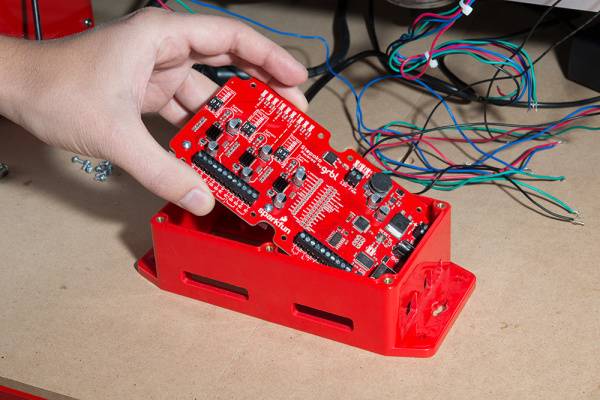
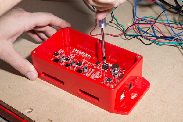
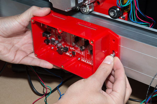
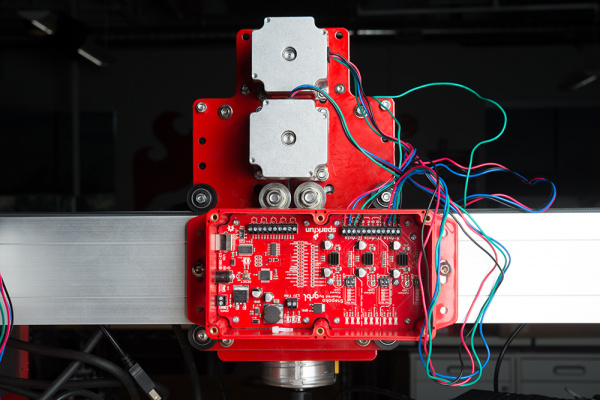
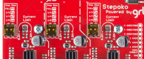
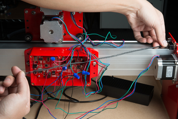

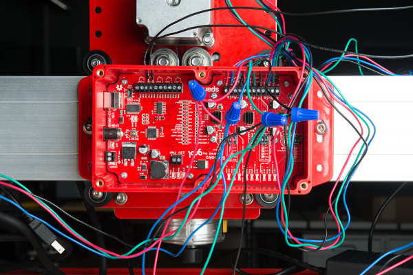
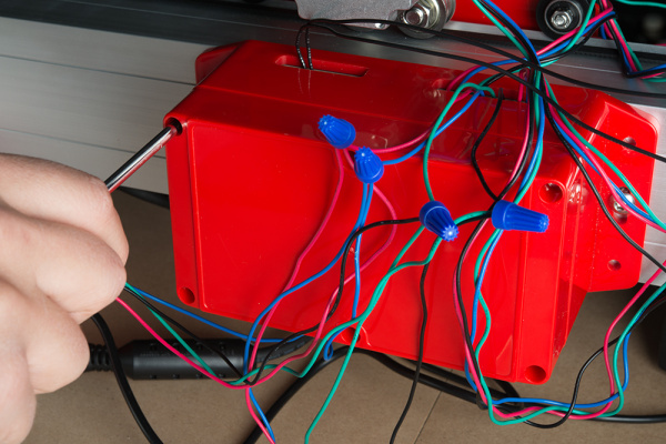
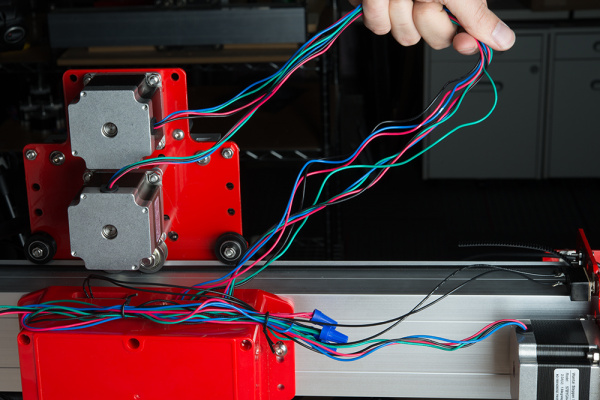
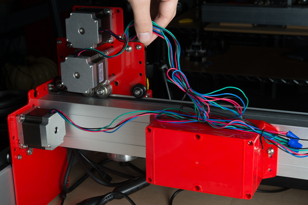


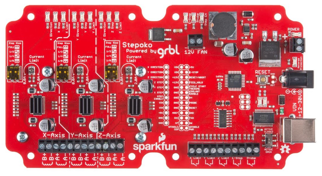


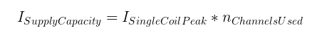


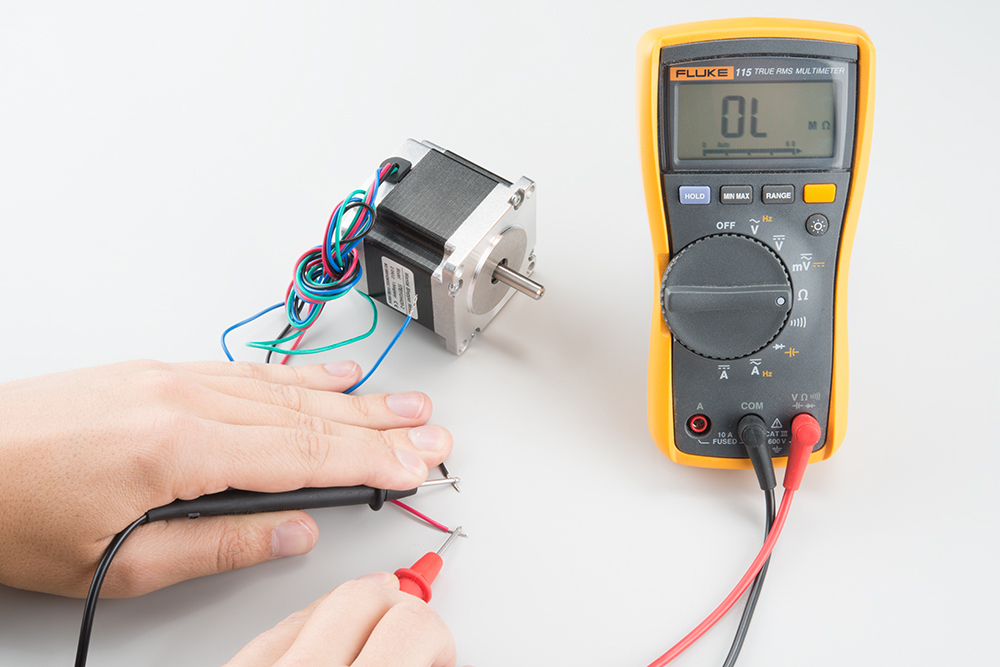
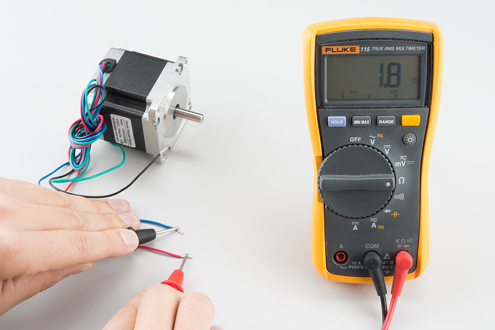
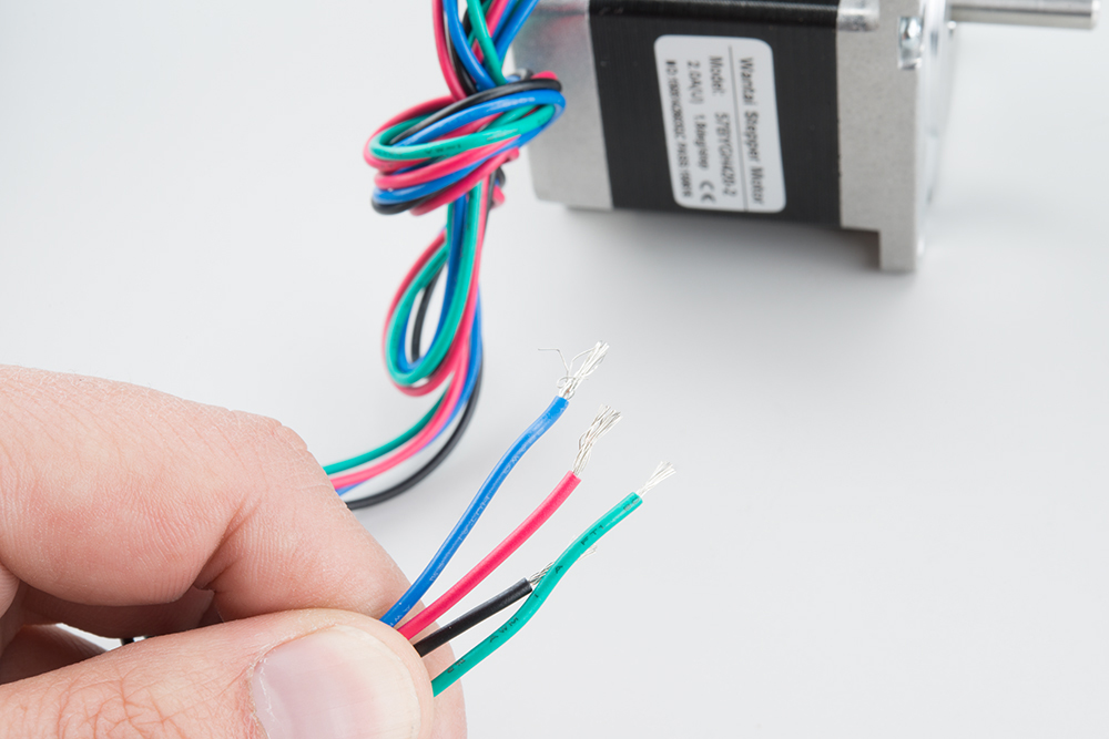
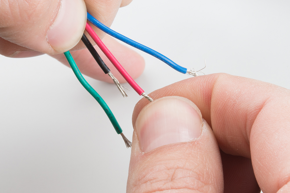

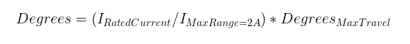
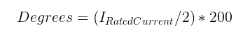


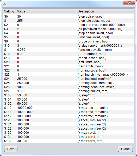

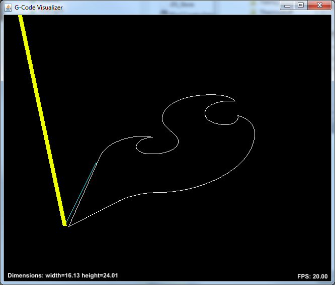


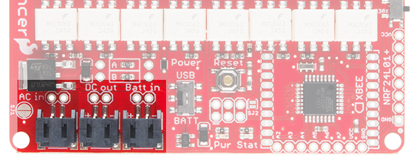

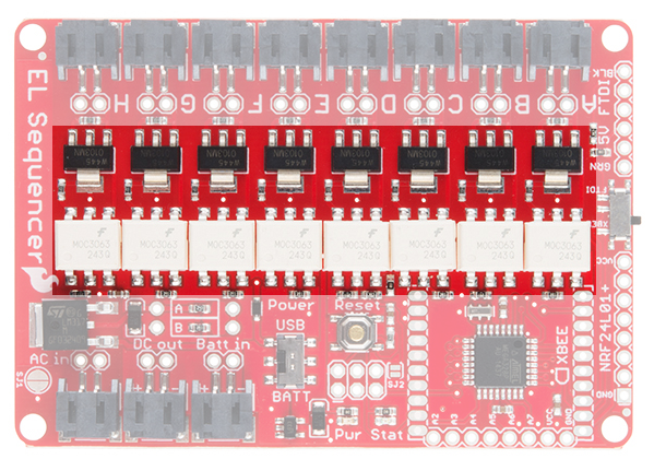
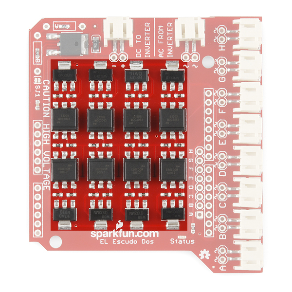
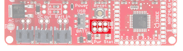
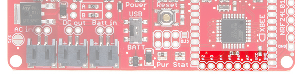
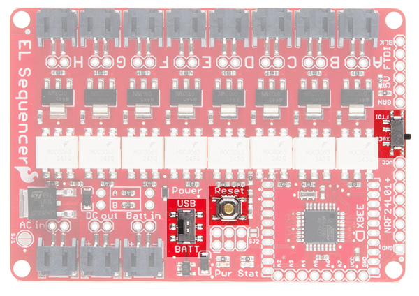
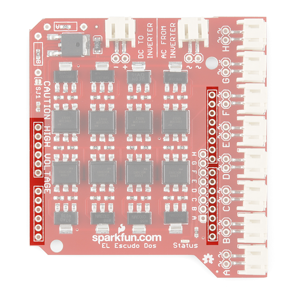

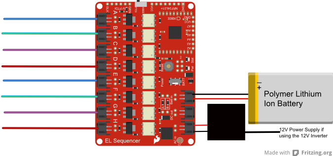

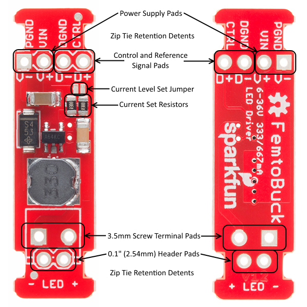
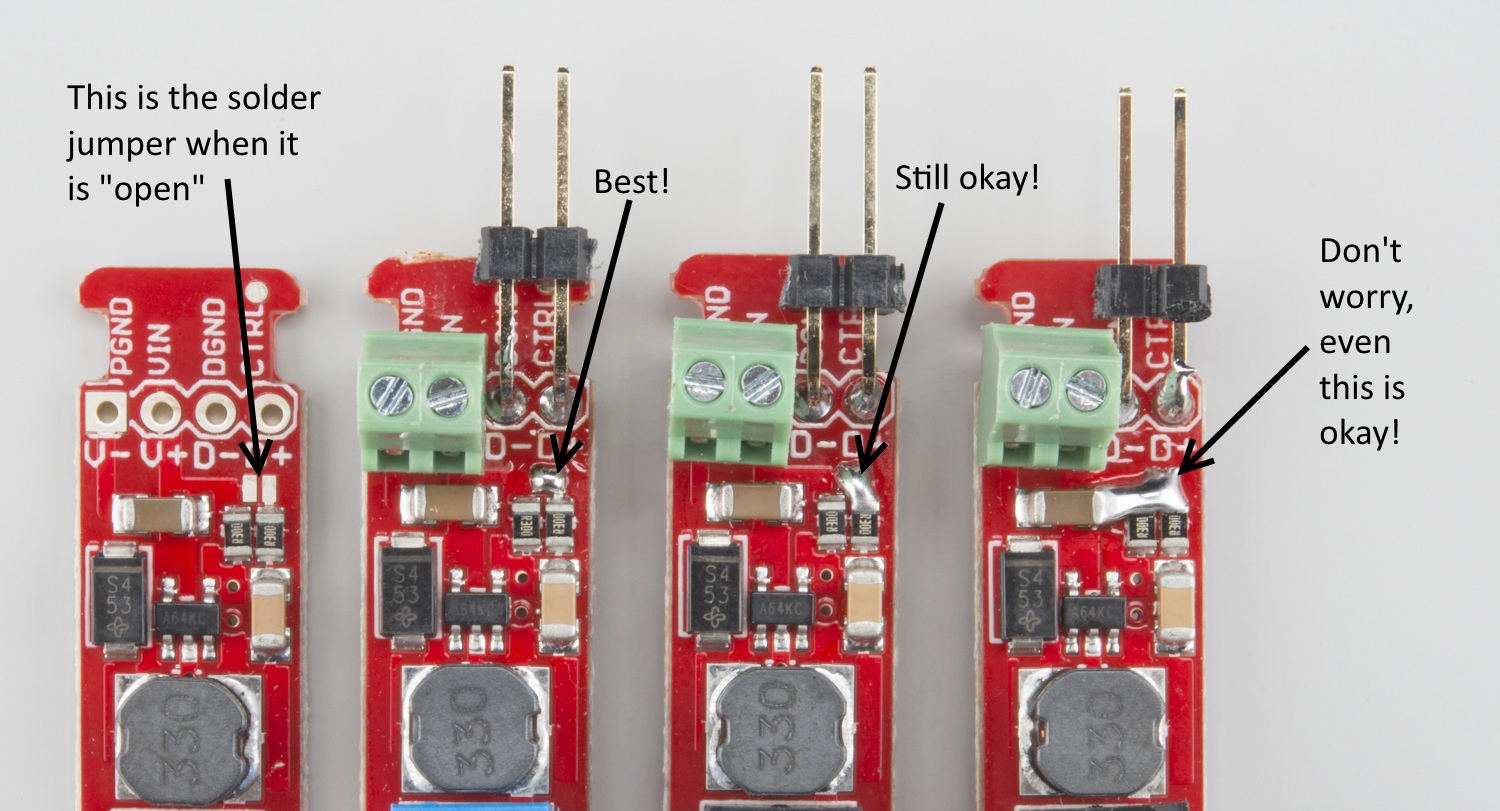


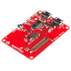
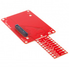
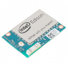


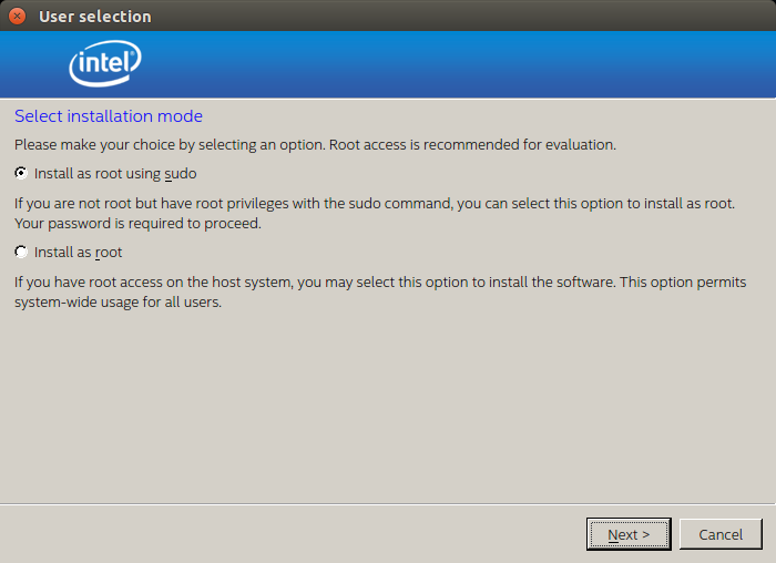


](http://cdn.sparkfun.com/assets/learn_tutorials/4/4/8/FW_Update_01_annotated.png)
](http://cdn.sparkfun.com/assets/learn_tutorials/4/4/8/FW_Update_02_annotated.png)