Introduction
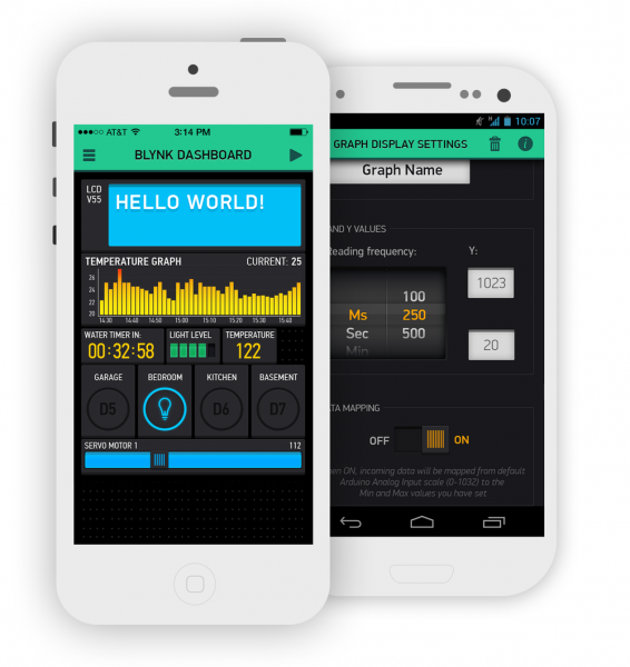
So you’ve provisioned your SparkFun Blynk Board– connected it to your Wi-Fi network and started using the zeRGBa to control the RGB LED – now what? Time to build some projects!
![BotaniTweet project in action]()
Project 12 of this guide: creating a sentient, tweeting plant.
This tutorial will walk you through fourteen Blynk projects, which range from blinking an LED with a smartphone to setting up a tweeting, moisture-sensing house plant.
This tutorial follows our "Getting Started with the SparkFun Blynk Board" tutorial, which demonstrates how to provision your Blynk Board and get it connected to a Blynk project.
Have you just powered up your Blynk Board? You need to get your board on Wi-Fi first! Head over to the Getting Started tutorial to learn how.
All of the projects in this guide are pre-loaded into the Blynk Board. That means you don’t have to write any code – just drag and drop some Blynk widgets, configure some settings and play! This tutorial will help familiarize you with both the Blynk Board hardware and the Blynk app, so, once you’re ready, you can jump into customizing the Blynk Board code and creating a project of your own.
Suggested Reading
We'll be (over-)using electrical engineering terms like "voltage", "digital", "analog", and "signal" throughout this tutorial, but that doesn't mean you need to be an electrical engineer to know what they mean.
We pride ourselves on our comprehensive list of conceptual tutorials, which cover topics ranging from basics, like What is Electricity? or Voltage, Current, Resistance, and Ohm's Law to more advanced tutorials, like Logic Levels and I2C.
What is Electricity?
Not an easy question, but in this tutorial we will shed some light on what is electricity!
Logic Levels
Learn the difference between 3.3 V and 5 V devices.
I2C
An introduction to I2C – one of the main embedded communications protocols in use today.
We'll link to tutorials as we introduce new concepts throughout this tutorial. If you ever feel like you're in too deep, take a detour through some of those first!
Before we really dive into those projects, though, let’s familiarize ourselves with the Blynk Board and all of the components it features. Click the “Next Page” button below to proceed to the Blynk Board Overview section (or click “View as Single Page” to load the entire tutorial in all of its glory).
Blynk Board Overview
You’re probably already familiar with the most important Blynk Board component – the shiny RGB LED – but there’s a whole lot more included with the board. Throughout these projects you’ll explore everything the Blynk Board has to offer, but here’s a quick overview:
![Annotated diagram]()
Meet the Blynk Board Pins
The Blynk Board interfaces with the outside world using input/ouput (I/O) “pins”– tiny “fingers” that can either control real-world objects, like motors or LEDs, or read in values from sensors (for example light or position).
Each of the Blynk Board’s pins are accessible via the large, metal-encircled holes on the edge of the board. These large holes are designed to interface with alligator clip cables– a staple interface cable for beginner and advanced electrical engineers alike.
![Alligator clips clamped on the Blynk Board]()
Alligator clips clipped onto the Blynk Board, interfacing it with the physical world.
Each of the Blynk Board alligator-clippable-pins are labeled with white text towards the center of the board. The Blynk Board pins can be broken down into a few categories: general-purpose (GP), analog input, and power output.
General Purpose Input/Output (GPIO) Pins
There are eight “general-purpose” input/output (GPIO) pins. These are the “worker-bees” to the Blynk Board’s main processor “queen”. You can use them to control outputs – like LEDs or motors – or as inputs, gathering data from buttons, switches, encoders, and more.
| Pin Label | Notes |
|---|
| 12 | Input or PWM-capable output. |
|---|
| 13 | Input or PWM-capable output. |
|---|
| 15 | Input or PWM-capable output. |
|---|
| 16 | Input with pull-down resistor. |
|---|
| 0 | Input; connected to on-board button. |
|---|
| 5 | Output; connected to on-board LED. |
|---|
We recommend against using the RX and TX pins unless you really need them, but the rest are free for interfacing with the rest of the world as you desire!
Analog Input (ADC) Pin
A very special pin labeled “ADC” sports the Blynk Board’s analog-to-digital converter (ADC). This pin translates analog voltages to the digital 1’s and 0’s a computer can understand.
![Blynk Board ADC input]()
This pin is mostly used to read the values of real-world sensors – you can connect it to light sensors, motion sensors, flex sensors, and all sorts of other physical-world-sensing electronic components.
Power Outputs
In addition to the Blynk Board’s I/O pins, the power rails are also broken out to alligator-clip pins. These are the pins labeled “VIN”, “3.3V”, and “GND”.
![Blynk Board power outputs]()
You’ll get very accustomed to using these pins – especially the ground pin. They have all sorts of uses – ranging from powering motors to providing a reference voltage for a potentiometer.
Recommended Materials
While the Blynk Board includes a variety of inputs and outputs, we could never fit as much onto the board as we’d like. This page lists the handful of wires, sensors, LEDs, and other electronic components that tie-in well with the Blynk Board projects.
If you have the Blynk Board IoT Starter Kit, you’re probably already set up with most of these components. (Everything except the PowerSwitch Tail, in fact.)
Don't worry if your electronics toolbox isn't outfitted with one, or more, of these components yet!
We've designed the projects in this guide to all be do-able regardless of whether-or-not you have external components plugged into the board. (You may just get very tired of using the Blynk Board's temp/humidity sensor input, or RGB LED output.)
Enough reading, time for blinking/Blynking! Our first project explores one of the most fundamental concepts in electronics and programming: digital input and output. A digital signal has a finite number of states – in fact, it usually only has two possible conditions: ON (a.k.a. HIGH, 1) or OFF (a.k.a. LOW, 0).
![Blinking LED]()
💡Blink – the Electronics "Hello, Word"
As simple as this project may look, blinking an LED is the first step towards a long, fruitful journey of electronics tinkering. You'd be surprised at how many other real-world objects you can manipulate with a simple HIGH/LOW digital signal: you can turn a Relay on or off -- which can, in turn, control power to any household electronics. You can use digital signals to spin motors (or at least drive a motor controller). Or you can quickly pulse a digital signal to produce tones in a buzzer.
![Blynk project layout]()
Using Blynk’s Button widget, we can send a digital signal to the Blynk Board. If we attach that input to the right output on the Blynk board, we can use the HIGH/LOW signal to turn an LED on or off.
Blynk Setup
By now you should already have a Blynk project – complete with an LED-controlling zeRGBa – running on your phone. We’re going to continue using this project for our experimenting in this guide.
Don't delete the BlynkMe project! We'll continue using the provisioning-provided Blynk project throughout this tutorial. Later, after coming up with a Blynk project of your own, you can create more projects (or continue using this one).
Make sure you keep the Blynk Board QR-Code Card– although it won't supply your account with more energy, it can be used to re-provision the Blynk Board.
Removing Widgets
Since we’ll be using the same project throughout, you’ll eventually want to make some space for more/bigger widgets. So to begin, let’s clear the project out (don’t worry, the zeRGBa and LCD are coming back soon!).
To delete widgets from your a Blynk project, follow these steps:
- If your project is still running, stop it by clicking the square stop button in the upper right-hand corner.
- Tap the zeRGBa widget to open its settings.
- Scroll down to the bottom of the zeRGBa settings and press the red delete button.
- Confirm the deletion – on iOS click Delete Widget, on an Android hit “OK” on the popup dialog.
![Deleting a Blynk Widget]()
Follow the same set of steps to remove the LCD widget from the project.
Adding a Button to Pin 5
Let’s start by adding a simple button widget. Here’s how:
- Make sure your project is not running– the upper-right icon should be a triangular play button.
- Touch anywhere in the blank, gray project space. A toolbox should open up on the right side with all of your widgets to choose from.
![Blynk Widget box]()
- Select the Button widget by tapping it. You'll find it at the top of the "Controllers" list.
- Tap and hold the button widget to drag it anywhere within the project space. You've got a lot of room to work with right now.
![Positioning the button]()
- Touch the Button Widget to bring up the settings page, and modify these values:
- Name: "LED"– While the widget is a button, we'll be using it to control an LED.
- Output: 5– in the "Digital" list.
- Color: Click the red circle to change the color of the button. Try blue, since we're toggling a blue LED!
- Mode: Take your pick. Try them both!
![Configuring the Button Settings]()
- Confirm the settings.
- If you're using an Android, hit the back arrow in the upper-left corner
- If you're using an iOS device, hit the OK button.
Now that the button is all configured, run the project by tapping the play button in the upper-right corner of the screen.
Blynk Run
Once the project is running, tap your new-blue button widget. When the widget is set to ON, the tiny blue LED should also turn on.
![Using the app to control the LED]()
Button: Push vs. Switch
Try switching the button’s mode between push and switch. Whenever you need to make changes to a widget’s settings tap the upper-right stop button, then tap the widget you’d like to configure. Once you’re done configuring, confirm the changes (“OK” button on iOS, upper-left back-arrow on Android), and set the project back to run mode.
If you have the widget set to PUSH, you’ll have to hold the button down to keep the LED on. SWITCH mode allows you to set it and leave it. Give them both a try and see which you prefer.
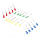
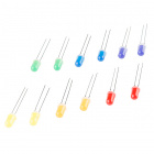
Going Further: Adding an Offboard LED
While it’s a useful status indicator, that blue LED is so small it’s barely visible above the shine of the RGB LED. Combining a couple alligator clip cables, with a 330Ω resistor, and an LED of your choice, you can offboard the Blynk Board’s LED control.
In stock
COM-12062
We all know that you can never get too many LEDs. Don't worry, we've got you covered. This is a pack of basic red, yellow, bl…
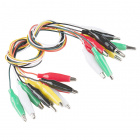
5In stock
PRT-12978
Alligator clips (or Crocodile clips, if you prefer) are likely to be the most useful thing on your workbench besides the work…
3In stock
COM-12903
Sometimes when you have too many choices, it's hard to make a good decision. In fact, there are times when you just want a ba…
2In stock
COM-11507
1/6 Watt, +/- 5% tolerance PTH resistors. Commonly used in breadboards and perf boards, these 330Ohm resistors make excellent…
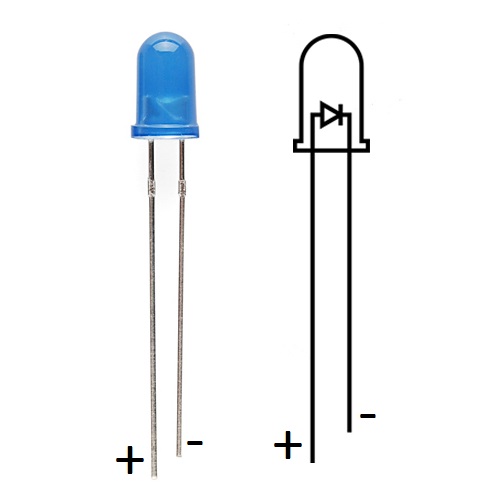
2First, locate the LED’s positive, anode pin– you’ll be able to identify it by the longer leg.
![Identifying LED Polarity]()
Bend the long leg out 90°, then twist it together with one of the legs of the 330Ω resistor (either end, resistors aren’t polarized).
![LED and resistor legs twisted together]()
Next grab two alligator clip cables– one black, the other green (although the color doesn’t matter, using black for the ground wire is a nice convention to follow). Clamp one end of the black cable to the LED, and clamp one end of the other cable to the resistor.
![Alligator clips clamped to legs]()
Plug the other end of the black cable into the “GND” pin, and the other end of the green cable to the “5” pin.
![Alligator clips clamped to board]()
Now flick the Blynk app’s LED button again. Not only will the blue LED toggle, but your offboard LED should too! If the LED isn’t turning on, try swapping the alligator clip cables around on the LED and resistor legs.
Changing the Digital Pins
Now try driving the offboard LED using pin 12. Move the green alligator clip from the “5” pin to the “12”.
You’ll also need to either add another button widget, or change the settings of the one you’ve already laid down.
![Adding a second button to pin 12]()
Feel free to repeat the same experiment on pins 13 and 15! Avoid pins 0 and 16 for now, they’ll be used as inputs later in this tutorial.
In the previous experiment, we used the button widget to receive a digital input and produce a digital output– pressing a button on the app toggled an LED on the board. Now let’s do the opposite – use a button on the Blynk Board to toggle an “LED” in the app.
![Blinking LED Widget]()
This project introduces the LED widget– a simple tool for indicating the digital status of a Blynk Board input.
Blynk Setup
There should still be plenty of room in the Blynk Board project for the LED widget. You can either keep the button widget from the previous project, or remove it to save a little space. If it’s not bugging you, we suggest keeping the button widget around– you’ll be re-configuring and using it again soon.
Saving and Re-Purposing Widgets
Widgets cost Blynk energy! Even if you get most of that energy refunded when you remove it from a project, it can take a psychological toll – every energy point is precious!
Throughout this guide, never feel obligated to remove any widget from a project – even if you're not using it in the active project. That's especially true with the button and value widgets, which will be reocurring throughout this project guide.
Add an LED Widget to V1
Like the button widget before, follow these steps to add an LED widget:
- If your project is running touch the sqaure button in the upper-right corner to stop it.
- Touch anywhere in the blank project space to open the widget box.
- Select the LED widget near the top of the "Displays" section.
![Adding an LED from the Widget box]()
- Drag and position the LED widget anywhere in your project space.
- Touch the LED widget to open up the Settings dialog, and adjust these values:
- Name: "Btn" (not "Button" for reasons...)
- Pin: V1. Any pin beginning with a "V" will be found under the "Virtual" list.
- Color: Touch the red circle to change the color of your LED. You can even set it up as a mythical black LED.
![Configuring the LED settings]()
Touch the Play button in the upper-right corner to start the project back up.
Blynk Run
With your project running, push down on the little gold circle of the Blynk Board’s push-button.
![Pressing the button on the Blynk Board]()
While you’re holding the button down, you should see the Blynk project’s LED illuminate. Depending on lagtime, the LED may take a couple seconds to notice the button is pressed. Releasing the button will turn the LED back off.
Virtual Pins
V1, which we're using in this example to control the Blynk LED state, is one of the Blynk project's 32 virtual pins– a custom-programmed input or output, that can read or write values of all types to the Blynk Board or app.
Instead of directly reading or writing to digital or analog pins, virtual pins have to be implemented in firmware (the code running on the board). When you start writing your own Blynk programs, you can re-define these virtual pins to read or write any value, or to control anything that meets your fancy. For now, though, these pins are all defined in the Blynk Board's firmware; you should discover nearly all 32 of them throughout this guide.
Going Further: Launch a Rocket
Blynk LED widgets are great for indicating the digital status of any input pin, or any other virtual pin. You can tie just about any digital input into the 0 pin on the Blynk Board.
For example, grab a couple alligator clips and a rocket-launcher-style toggle switch, then connect them up like this:
![Connecting clips to the rocket launcher switch]()
Be careful not to allow the two alligator clips to touch – it’s a tight fit, but it works!
Then connect the black wire to GND and the colored cable to 0.
Now, turning on the LED is even more satisfying! When the toggle switch is set to “ON”, the LED should illuminate.
Project 3: Slide-Dimming LEDs
Now that you’re an expert on digital inputs and outputs, it’s time to throw a curveball with analog signals. Analog values can take on any shape and be any value among the infinite possibilities in our world.
As with digital signals, the Blynk Board can also produce analog outputs or read in analog inputs. By producing an analog input, the Blynk Board can dim an LED, instead of being left with either turning it on or off.
![Blynk regular and large sliders]()
To produce analog outputs, we’ll use the Slider widget in the Blynk app. The slider allows you to precisely set the value of an output on the Blynk Board – it’s not just ON or OFF. Now, you can set a value between 0-255, 0-1023, -8 to +8, or whatever else you please.
Pulse-Width Modulation (PWM)
To be honest, the Blynk Board actually can't produce truly analog outputs. Instead, it quickly pulses a digital signal high and low to produce an average voltage in a technique called pulse-width modulation (PWM).
PWM waves aren't really analog, but they go up and down so fast that a lot of components – like LEDs – can't tell the difference.
Blynk Setup
Once again, you should have plenty of room left in your project – only delete widgets if you want to clean up a bit. However, if you still have the button triggering the pin 5 blue LED, you’ll need to disconnect it in order to use a slider on the pin.
One Pin At a Time
When configured to monitor or control a pin, a Blynk widget lays claim over that pin until it's disconnected. In fact, in most cases the Blynk app won't let you assign one pin to multiple widgets at once.
By limiting pin-control to one widget at time, we make sure the Blynk Board can't get confused – you wouldn't like it when it's confused.
Disconnect the Button From Pin 5
- Stop the project.
- Touch the button to bring up its settings.
- Change the pin to the dash (–) and hit OK a couple times.
![Disconnnect the button from pin 5]()
If you still have a button controlling pin 5, disconnect it by clearing the pin setting.
The button will remain in your project – you won’t lose any energy – but it’ll be disconnected from any digital or virtual pins for now. Pressing it while the project is running won’t have any effect.
Connect a Slider Widget to Pin 5
- Touch anywhere in the blank project space to open the widget box.
- Select the Slider near the top of the "Controllers" section.
- Drag and position the Slider widget anywhere in your project space.
- Touch the Slider widget to open up the Settings dialog, and adjust these values:
- Name: "LED Dimming"– we're using it to control the LED
- Pin: 5– under the "Digital" list
- Range: 0⟷255, covering the full PWM output range.
- Color: Touch the red circle to change the color of your slider.
![Adjusting the slider settings]()
Confirm the settings, and run the project.
Blynk Run
Once the project is running, try grabbing the slider and gradually moving it from one side to the other. The small, blue LED should brighten and dim as you do so. The closer the slider value is to 0, the dimmer it will be. 255 is 100% ON and 0 is totally off.
You can also give the large slider a try. Both sliders accomplish the same task, but the large sliders tend to provide a bit more precision over the pin’s value.
Going Further: RGB Precision Control
Sliders can take on all sorts of applications in a Blynk project. In addition to directly controlling a digital pin’s PWM value, they can be used to provide a range of input to firmware running on the Blynk Board.
In fact, we’ve set up virtual pins 2, 3, and 4 to individually control the red, green, and blue channels of the RGB LED. Try adding three more sliders:
| Widget | Name | Pin | Minimum | Maximum |
|---|
| Large Slider | Red | V2 | 0 | 255 |
| Large Slider | Green | V3 | 0 | 255 |
| Large Slider | Blue | V4 | 0 | 255 |
![Configuring the RGB sliders]()
Run the project, and slide around. You may find that the three individual sliders provide more precise control over the mixed color of the RGB LED compared to the zeRGBa widget.
![Sliding the RGB LED]()
Brightness Control
Time for another admission of guilt: We’ve been holding back the full awe – and terror – of the Blynk Board’s RGB LED. In fact, we’ve been limiting the LED brightness to about 12.5% of it’s full power.
To set the maximum range of the RGB LED add a slider to V15– you can re-purpose the small slider widget controlling the pin 5 LED, if you’d like. Name it “Brightness”, and once again set the range to 0-255.
![Adding a brightness slider]()
Play with all four sliders to see the full range of colors you can create. Just be careful! That LED really can get blindingly bright.
Dimming LEDs isn’t all the sliders are good for. Later projects will use them as input control, setting values like Twitter timers, moisture thresholds, and sensor update rates.
Project 4: Temperature and Humidity Values
Blynk’s Value widget is the workhorse of many-a-Blynk project. Set to a digital pin, it can display the real-time HIGH or LOW values of the pin. Set to the proper virtual pin, it can display as much information as you can fit into four characters.
![Example value widgets]()
In this project, we’ll use two-or-three Blynk value widgets to read how hot your Blynk Board is running and find out whether it’s hydrated enough.
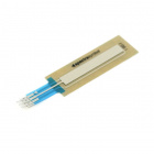
This is the first project to use the Blynk Board’s on-board temperature and humidity sensor– the tiny, white scare adjacent to the “12” pin. This is the first step towards creating environment-sensing projects – for example, you could wire up a relay to turn a fan on or off depending on the local weather conditions.
Blynk Setup
Clean up your Blynk Board project as necessary, make sure the project is stopped, and add three new value widgets.
Add Three Value Widgets to V5, V6, and V7
The Value widgets are located at the top of the “Displays” category. Once in the project, set the widgets up like this:
| Name | Pin | Min | Max | Frequency |
|---|
| Temp F | V5 | – | – | 1 sec |
| Temp C | V6 | – | – | 1 sec |
| Humidity | V7 | – | – | 1 sec |
![Adjusting the value settings]()
As always, feel free to adjust your widget colors to your heart’s delight.
The frequency setting controls how often the Blynk app asks the Blynk Board for updated values. You can set it anywhere from four times a second (250ms) to a little less than a minute. Don’t set it to push, though, as the Blynk Board firmware isn’t configured to “push” these values to the app.
For these virtual pins, the range (defaulted to 0-1023) won’t have any effect on the displayed value – you can ignore them.
Once you’ve set all three value widget’s up, run the project.
Blynk Run
A second-or-so after you hit Play, you should see the three values begin to update. “Temp F” and “Temp C” display the temperature in Fahrenheit and Celsius, respectively, while “Humidity” displays the relative humidity as a percentage.
![Temperature and humidity values displayed]()
The most effective way to interact with this project is to get up close to the white temperature/humidity sensor and blow on it. Your breath should quickly raise the humidity reading, before it slowly drops back down. Or, if you can take your Blynk Board outside, go check the environment readings against your local weatherman.
Hot blooded
You can probably tell by placing a finger under the Blynk Board that it tends to run hot. Don't worry! Your desk probably isn't 90°F.
The humidity sensor should still be correct, but, to get a more accurate temperature reading, try unplugging the board, letting it cool off for a minute-or-so, and plugging it back in.
Going Further
Continue to play around with the value widget settings to get a feel for the update rate. Try setting it as fast as possible (250ms) – the Blynk Board should be able to keep up.
You can use the value widget for just about any Blynk input built into the firmware. For example, try setting either the “Temp F” or “Temp C” widgets to V1 (you may have to disconnect the LED first). Now, when you press the button, you’ll reinforce the idea that 255 is equivalent to 100% ON, and 0 is completely off.
Or – if you want to get a jump-start on the next project – set one of the value widget’s pin’s to ADC0, under the “Analog” list. What are these 0-1023 values all about? All of you questions will be answered in the next project!
Project 5: Gauging the Analog-to-Digital Converter
To read in analog inputs, the Blynk Board uses a special-purpose pin called an analog-to-digital converter (ADC). An ADC measure the voltage at a set pin and turns that into a digital value. The ADC on the Blynk Board produces a value between 0 and 1023 – 0 being 0V/LOW/OFF, 1023 being 3.3V/HIGH/ON, and 512 being somewhere in the middle ~1.65V.
![Gague widget example]()
There are a variety of widgets that can be used to display the voltage at the ADC pin. In this project, we’ll use the Gauge widget, which provides the real-time reading on the ADC pin in a nice, proportional manner.
Hardware Setup
The Blynk Board’s ADC input is floating– not electrically connected to any circuitry. Without something connected to the pin, the voltage may wildly fluctuate, so to produce a reliable, steady voltage, we’ll need to wire it up.
There are a huge variety of analog-signal producing electronic components out there, but the most traditional is a potentiometer. “Pots” come in all sorts of shapes and sizes from rotary to linear to soft.
In stock
COM-09806
There are lots of trimpots out there. Some are very large, some so small they require a screwdriver. Here at SparkFun, we jus…
6In stock
COM-09119
A simple slide potentiometer can go a long way. Rated at 10kOhm and 0.5W. Comes with solder tab connections. The taper profil…
In stock
COM-09939
An adjustable potentiometer can open up many interesting user interfaces. Turn the pot and the resistance changes. Connect VC…
6In stock
SEN-08680
These are very thin variable potentiometers. By pressing down on various parts of the strip, the resistance linearly changes …
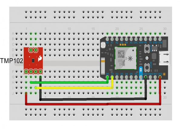
1To really get the most out of this project, consider grabbing a sliding linear potentiometer and three alligator clip cables. Wire up the bottom of the slide pot like below – red cable on the pin labeled “1”, yellow connected to “2” and black connected to “3”.
![Hooking alligator clips to the slide pot]()
Then route the other ends of the alligator-clip cables like below – red to 3.3V, black to GND, and yellow to ADC.
![Slide pot connected to the Blynk Board]()
The yellow cable – terminating on the ADC pin – will carry a voltage that varies between 0V (GND) and 3.3V, depending on the position of the slide pot.
Blynk Setup
The Gauge widget takes up a good chunk of room, so you may need to remove some previous widgets before adding it. Keep a value widget from the previous experiment – we’ll use it to display the calculated voltage.
Connect a Gauge to ADC
You’ll find the Gauge widget under the “Displays” section. Once it’s added, modify the settings like so:
| Name | Pin | Min | Max | Frequency |
|---|
| ADC | ADC (under "Analog") | 0 | 1023 | 250 ms |
![ADC gauge settings]()
We’re reading directly from the ADC – the Blynk Board’s analog-to-digital converter input. The 10-bit ADC produces a value between 0 and 1023, which is a value proportional to a voltage between 0 and about 3.3V. So, an ADC reading of 0 equates to 0V, 1023 equals 3.3V, and 512 is about 1.75V.
Repurpose a Value Widget to V8
If you don’t want continuously do that voltage-converting math in your head, modify a value widget to display V8, and set the name to Voltage.
![Value widget settings]()
The Blynk Board will convert the ADC reading to an equivalent voltage for you.
Blynk Run
Run the project, and watch for the gauge to settle in on a value. If you have a potentiometer wired up, the reading should remain rather steady. Try moving the wiper up and down.
![Project action shot]()
If you don't have a potentiometer handy or any way of connecting it to the Blynk board, don't fret. You're a variable resistor too! You can test out the ADC by putting a finger on the "ADC" pin.
You should be able to move the gauge around by placing another finger on either the "GND", "VIN", or "3.3V".
(Electricity is running through your body, but it's a minuscule, insignificant amount. You don't have anything to worry about.)
There are a huge variety of analog-signal producing electronic components out there. You could wire up an accelerometer, stick the circuit on a washer/dryer, and check the analog readings to observe if your laundry is done or not. Or wire up a force-sensitive resistor, hide it under your doormat, and check if anyone’s at the front door.
Later in this guide, we’ll wire the ADC up to a Soil Moisture sensor and connect your houseplant to your twitter account, so it can notify the world when it’s thirsty.
Project 6: Automating With the Timer
A large chunk of Internet-of-Things projects revolve around home automation– a classic example of which is automatically switching your lights on and off. Using the Blynk Timer widget, you can trigger specific outputs to fire at any time of the day – even if your app is closed and your smart device is off!
![Timer example]()
The timer’s pair of settings include a start time and a stop time. When the start time is triggered, the timer’s configured pin turns HIGH. When the stop time is met, the pin goes back into a LOW state.
Blynk Setup
All you’ll need for this project is the simple but powerful Timer widget.
Add a Timer Widget on V9
Add the Timer widget to your project – you’ll find it under the “Controllers” list. Then tap the widget to open up the settings page.
Depending on what you have plugged into the board, there are a variety of options available to you on the Pin setting. For now, let’s use it to trigger an RGB light show. Set the Timer’s pin to V9, which is configured to start Rainbow Mode on the Blynk Board’s RGB LED.
![Setting a timer to V9]()
Alternatively, you can use it to toggle any digital pin – like the pin 5 blue LED, or an external LED on pins 12 or 13.
For experimenting purposes, set the start time to about a minute from now, and the stop time to 30-60 seconds later. Once you get a feel for the timer, you can start using it more strategically.
As usual, give it any name and color you please.
Blynk Run
Once you’ve set your timer up, run the project. Hopefully you get it running before the timer’s programmed Start Time! If not, stop and increase the start time another 30 seconds-or-so.
The timer has a hidden feature in run mode: if you tap it you can switch between the start-time display and a countdown display. Countdown display mode is especially handy while your just testing around.
![LED Timer expiration]()
Once the timer triggers it will fade in and out to indicate the pin is on. If the timer’s fading, your pin should be active. Watch the RGB do its hypnotic rainbow dance.
![RGB LED timer active]()
Once the timer hits the Stop Time, the LED should return to its previous duties – waiting to shine another day (literally, you better adjust the start time again).
Going Further: Controlling Lamps With the Power-Switch Tail
The PowerSwitch Tail is one of our favorite general-purpose components in the catalog. With a simple HIGH/LOW signal from the Blynk Board, you can use the PowerSwitch Tail to control power to any device you would otherwise connect to a wall outlet. Best of all, it’s completely enclosed and totally safe.
In stock
COM-10747
Want to control a standard wall outlet device with your micro controller, but don't want to mess with the high voltage wiring…
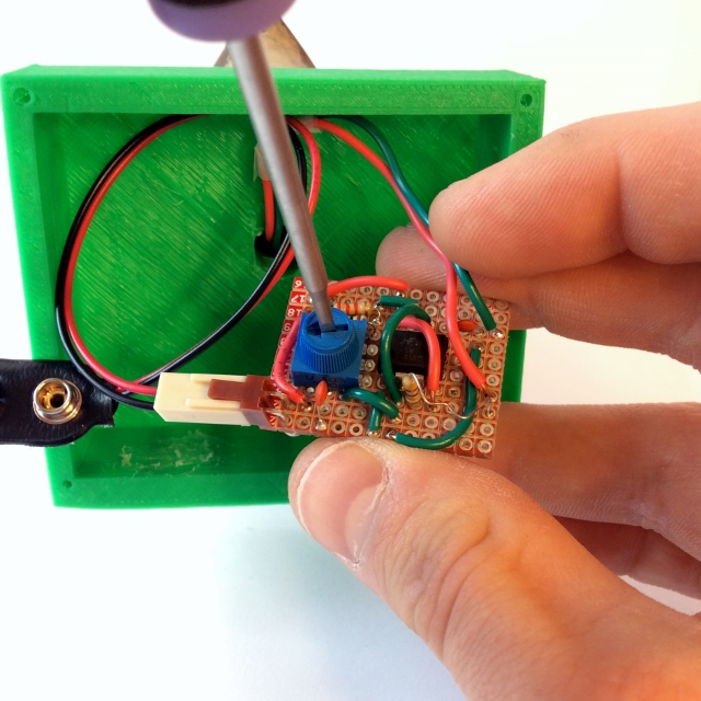
3First, use your screwdriver to securely wire the jumpers into the PowerSwitch Tail’s “+IN” and “-IN” pins (leave the “Ground” pin unconnected). Then clip alligator cables to the ends of those wires. Wire the “-IN”-connected cable to the Blynk Board’s GND pin, and the “+IN” cable to the Blynk Board’s pin 12.
![Powerswitch tail connected to Blynk Board]()
Plug a lamp, fan, or any device you’d like to automate into the PowerSwitch Tail’s 3-prong female connector. Then connect male 3-prong connector into the wall.
Then set up a new timer – this time connected to pin 12. Adjust the start and stop times, and have the Blynk Board make sure your lights are off when you’re out of the house.
The 16x2 Liquid-Crystal Display– a 16-column, 2-row LCD, which can display any combination of up to 32 alphanumeric characters – is one of the most commonly recurring components in electronic projects. It’s simple to use, and has they ability to convey a wealth of information pertaining to your project.
![Alpha-numeric 16x2 LCD]()
Blynk’s LCD widget is similarly useful in displaying diagnostic and other Blynk-project information. In this project, we’ll the LCD widget to display everything from the Blynk Board’s temperature and humidity readings, to the length of time it’s been up-and-running.
Blynk Setup
This project requires the LCD widget as well as three button widgets, which you can repurpose from the previous projects.
Connect an LCD Widget to V10
Add an LCD widget from the “Displays” section of the widget box, and tap it to bring up the settings page.
Before adjusting anything else, slide the Simple/Advanced slider to Advanced. Then set the pin to V10, and adjust the background and text color as you please (can’t beat white text on black).
![LCD Widget settings]()
Add Button Widgets to V11, V12, and V13
Set the three buttons up to trigger virtual pins 11, 12, and 13. Leave them in Push mode:
| Name | Pin |
|---|
| T/H | V11 |
| Inputs | V12 |
| Runtime | V13 |
![Button settings]()
Blynk Run
Once the button’s are set, you’re ready to run. Until you hit one of the three buttons, the LCD may print a greeting message. But that will quickly fade once you trigger V11, 12 or 13.
![Button running]()
Although it takes up a lot of room initially, you can see how valuable the LCD is – and the wealth of information and text it can display. While the Value widgets are limited to four characters, the LCD can display up to 32!
Project 8: Joystick Joyride
Joysticks are a staple input for a variety of control systems, including arcade gaming, RC-car driving, drone guiding, and assistive-tech maneuvering. They produce two pieces of data: position components along x- and y-axes. Using that data, a project can compute an angle between 0 and 360°, and use it to drive another mobile mechanism.
![Joystick example]()
Blynk’s take on the joystick is analogous to a physical joystick – as you move the center-stick around, it’ll send x- and y-axis values between 0 and 255 to the Blynk Board. What are we going to to do with that data? Spin a motor!
In stock
ROB-09065
Here is a simple, low-cost, high quality servo for all your mechatronic needs. This servo is very similar in size and specifi…
6To be more exact, we’re going to use the joystick to drive a servo motor. Servo’s are specialized motors with a built-in feedback system, which allows for precise control over the motor’s position. Instead of rotating continuously, like DC motors, a servo will move to a position you tell it to, and stop (unless it’s a continuous rotation servo. They’re useful for projects which require complete control over movement, like opening or closing a door to an automatic pet-feeder.
Hardware Setup
Most servo motor’s are terminated with a 0.1"-pitch 3-pin female header. To interface it with your Blynk Board, plug in a few male-to-male jumper wires into the servo socket (if you have the “connected” jumper wires, peel off a strip of three wires). Then clip a few alligator clip cables onto the ends of those wires.
![Wiring to a servo]()
Connect the cable wired to the servo’s black wire to GND, red to VIN, and the white signal wire to pin 15.
![Connecting servo to Blynk Board]()
Press one of the servo motor’s mounts onto the motor head, so you can better-see the spin of the motor.
Blynk Setup
In addition to the Joystick widget, this project can also optionally use a gauge (or value), and a slider. The slider controls the servo motor’s maximum angle, the gauge displays the calculated servo position (especially handy if you don’t have a servo connected).
Connect the Joystick to V14
Add a Joystick widget from the “Controllers” section. Slide the Split/Merge switch to Merge, and set the pin to V14. It’s not required, but we recommend setting autoreturn to off.
![Joystick settings]()
Connect a Slider to V16
If you have a slider in your project, you can re-purpose it to adjust the servo’s maximum angle. Set the pin to V16, and modify the range to make it easy to set your servo’s maximum value.
![Slider settings]()
Connect a Gauge or Value Widget to V17
Finally, the project produces a virtual output on V17 displaying the servo’s current angle. You can use a Value or Gauge widget to show this value. Neither are required – but it does provides feedback if you don’t have a servo motor attached.
![Gauge angle output settings]()
Modify the range of the gauge, or else you might not get the right feel for the servo’s position.
Blynk Run
Once everything’s set up, run it and joystick!
![Servo project in action]()
As you rotate the stick, the servo should noisily reposition itself along the angle you’ve set.
In the background the Blynk Board firmware is grabbing the x and y values of the joystick, doing some trigonometry on them to calculate an angle (in degrees), and pushing that calculation back out to V17.
Going Further
Once you’ve got the servo rotating, connect something physical up to it! How about an automatic fish feeder?
Scrounge around for a bottlecap, and screw it into the servo’s single-arm.
![alt text]()
Then slot the servo arm onto your servo motor head, and check the motion of the bottlecap – you may need to re-position the cap to get the rotation you need.
Now when you rotate the joystick, you’ll have a mobile-food-dumping apparatus – perfectly sized for a goldfish!
Project 9: Graphing Voltage
Electrical engineers love measuring voltage. Whether we’re using a multimeter to get a real-time view into a line’s potential, or a monitoring a periodic signal’s shape using an oscilloscope, monitoring voltage can be critical to project-debugging.
![Blynk graph widget]()
While we can’t really re-create an oscilloscope’s signal-triggering in Blynk, we can chart the Blynk Board’s voltage-over-time using the Graph widget. The graph widget periodically pulls in data from a virtual or physical pin, and creates either a bar or line graph representing how that input changes over time. You can set the graph to draw as fast as four times per second, or as slow as once-a-minute.
Hardware Setup
The Blynk Board’s input voltage will range anywhere from 3.7 to 6V – well outside the acceptable input range of 0-3.3V. So, to properly measure the input voltage, we’ll need to step it down using a voltage divider. Although it sounds complex, a voltage divider is actually just a pair of resistors sitting in between one voltage and another.
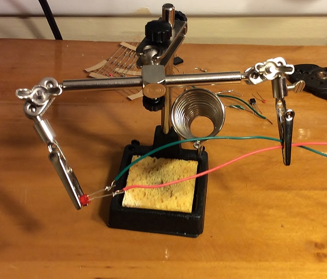
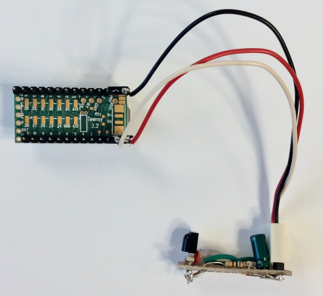
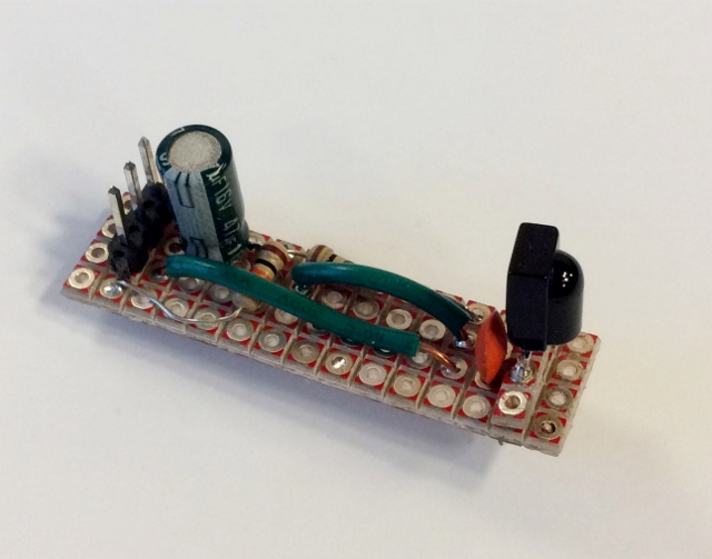
To create a voltage divider, first grab a couple 10kΩ resistors, and twist them together at the ends. Clip a yellow alligator clip to the twisted legs of the resistors, and connect red and black alligator cables to either of the other two legs.
![Two 10k's twisted together and clamped]()
Wire the other ends of the cables to ADC (yellow), VIN (red), and GND (black).
![Voltage divider connected to the Blynk Board]()
Voltage: divided. A voltage divider made out of two 10kΩ resistors will cut the voltage in half. So if the Blynk Board’s input voltage is 5V, the voltage at the ADC pin will only be 2.5V.
Blynk Setup
In addition to the graph widget, you can optionally add two value widget’s to help get a better view into the Blynk Board’s voltage measuring.
Connect the Graph to V20
You’ll find the Graph widget under the “Displays” section of the widget box. Add it, then tap it to configure. Set the pin to V20, and adjust the range to something like 0-6. Bump the update frequency up to 250ms.
![Graph settings]()
You can play with the Bar/Line switch, but a line graph seems to work best for this type of data.
Monitor the ADC and V8 With Value’s
For a bit more insight into the Blynk Board’s ADC reading, consider adding a couple value widgets to monitor the ADC pin and V8– the calculated ADC voltage.
![ADC value setting]()
![Voltage value setting]()
Blynk Run
See how steady that USB supply is. Try zooming the graph in, so the minimum is 4 and maximum is 6. The more “wiggles” in the signal, the noisier your supply is.
![Graphing the USB supply voltage]()
Fortunately, the Blynk Board regulates that input voltage, to create a nice, steady 3.3V supply. In fact, if you want to measure the 3.3V supply, simply swap the red cable from VIN to 3.3V. Is it steadier than the VIN supply?
Plotting Battery Voltage
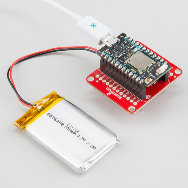
If you want to recreate that feeling as you watch your phone’s battery-life icon progressively empty – or the excitement of watching it charge, consider powering the Blynk Board with a LiPo Battery. There are a variety of Blynk Board-compatible LiPo batteries, we recommend either the 450mAh, 850mAh, or 1000mAh.
![Graphing the Blynk Board's batter voltage]()
If you set the read rate to the maximum – 59 seconds– and let the Board run for a while, you should begin to see an interesting downward slope while the battery discharges. Or plug the Blynk Board in and watch that slope incline.
Going Further
The graph widget should work for any of the Blynk Board’s output values. Try changing it to V5 or V6– see how the temperature fluctuates over time. You may need to adjust the graph’s range to actually see the line.
![alt text]()
Plotting the Blynk Board’s Fahrenheit temperature output.
Try plugging other Blynk Board outputs you’ve already used into the Graph widget. Make some interesting curves!
Project 10: Charting Lighting History
Blynk’s History Graph widget takes the standard graph to the next level. It allows you to compare a widget’s value to data from hours, days, weeks, even months back.
![History Graph example]()
In this project, we’ll plug readings from a light sensor into the History Graph. After you’ve let the project run for a while, you’ll be able to track the sun rise/set time, or find out if someone’s been snooping in a room when they’re not supposed to be.
Hardware Setup
To measure ambient light, we’re going to use a light-sensitive resistor called a photocell. When it’s pitch-black, the photocell morphs into a large, 10kΩ resistor, but when light shines on the cell, the device’s resistance drops closer to 1kΩ.
In stock
SEN-09088
This is a very small light sensor. A photocell changes (also called a [photodetector](http://en.wikipedia.org/wiki/Photodetec…
6To create a voltage for the Blynk Board’s ADC, using the photocell’s variable resistance, we need to pair it with a second resistor. The photocell and resistor will combine to create a variable voltage divider.
That second resistor should be somewhere in the middle of the photocell’s resistance range – right about 5kΩ. There aren’t any 5k&Omgea; resistors in the IoT Starter Kit, but it does include the means to create one! By combining two equal resistors in parallel, we can cut their total resistance in half.
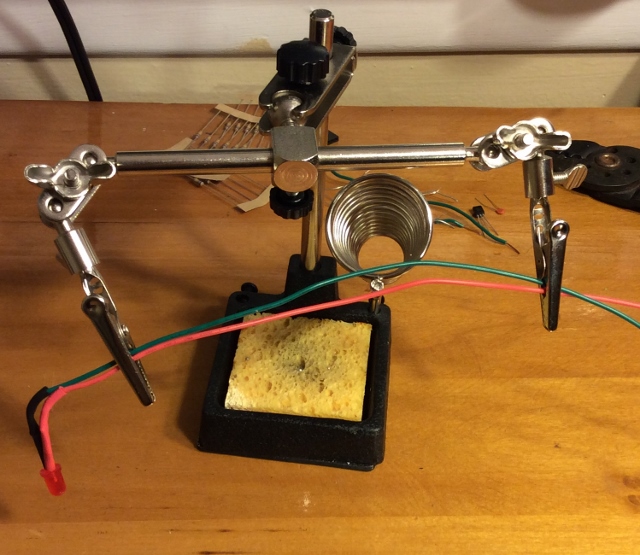
So, to create a 5kΩ resistor, grab two 10kΩ resistors, and twist them together in parallel – that is, twist the ends of both resistors together, so the bodies are touching each other. Then twist one leg of the photocell together with one shared leg of our new 5kΩ resistor.
![Photocell twisted with 2 10k resistors]()
Clip a yellow alligator cable to the middle legs – the behemoth that is two resistors and a photocell leg twisted together. Then clip a red cable onto the photocell’s leg, and a black cable onto the other resistor leg.
![Alligator clips clamped onto photocell circuit]()
On the Blynk Board – as you’re probably used to by now – clip the yellow to ADC, red to 3.3V, and black to GND.
![Photocell circuit connected to Blynk Board]()
This circuit will produce a higher voltage in the light and a lower voltage in the dark.
Blynk Setup
This Blynk project combines the History Graph widget with a Value widget to display the real-time light reading.
Configure a Value Widget
Before adding the graph, add a Value widget and configure it to read from V18.
![Configuring a value widget]()
Set the update rate to 1 second, and name the widget “Light.”
Add a History Graph Widget
Once the Value widget is in place, add a History Graph widget. In the settings, configure any one of the four PIN’s to V18.
![Configuring the History Graph widget]()
The textbox adjacent to the pin should automatically update to “Light” (or whatever the Value widget is configured as).
There is one quirk with the History Graph widget – it won’t directly pull or request a variable’s value. It relies on widgets like Value or Gauge to get the latest value from a virtual or physical pin.
Blynk Run
After running the project, begin by monitoring the Value widget’s reading – it should vary between 0 and 1023. See how high you can get the value reading by shining a light on it. (Hint: your phone might just have a bright LED to shine on the photocell.)
![Light tracker in action]()
Then cover up the photocell, or turn off your lights, and see how low you can get the reading. Or! Add a zeRGBa, turn the brightness up to max, and have the Blynk Board feed back into its own light sensor.
To really get the most out of the history widget, you need to leave the project running for at least an hour. If it’s about time to hang it up for the night, leave your Blynk project plugged in and graphing. Maybe you’ll catch someone sneaking in and turning the light on!
If you ever want to delete old history from the History Graph, swipe left on the graph (while the project is running), and select "Erase data."
Going Further
You can add up to four values to the History Graph – play around with the other three pins to see what other interesting info you can graph.
You may have to remove some of the previous pins to adjust the graph’s scale.
![Charting temperature and humidity]()
Celsius temperature and humidity – usually around the same order of magnitude – pair nicely on the graph together. Use the legend so you don’t forget which is which!
Project 11: Terminal Chat
The word “terminal” may instill images of 80’s hacker-kids playing a game of Global Thermonuclear War or 90’s Mr. Anderson’s following white rabbits, but, retro as they may sound, engineers still use terminals on a daily basis.
![Blynk terminal example]()
The Blynk Terminal widget allows you to pass endless information to and from the Blynk Board. It can be incredibly handy – in fact, we’ll use it in all four of the final projects to enter email addresses, pass debug information, and name your Blynk Board.
In this project, we’ll use the terminal on your Blynk app, and a terminal on your Blynk Board-connected computer to set up a “chat program.”
Hardware Setup
There aren’t any external components to connect to your Blynk Board in this experiment, but you may need to do some extra legwork to set up a terminal on your computer.
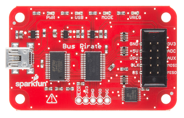
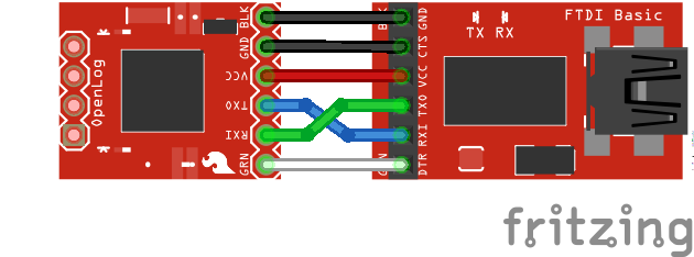
Install FTDI Drivers, Identify Your Serial Port
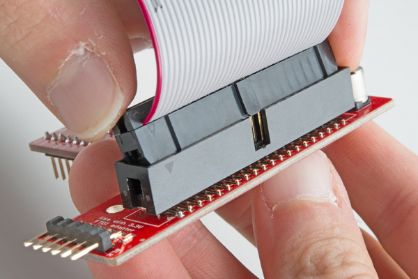
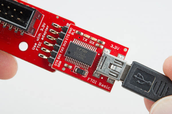
The Blynk Board uses a specialized chip called an “FTDI” to convert USB data to a more simple serial interface. If you’ve never used an FTDI-based device before, you’ll probably need to install drivers on your computer. Our How to Install FTDI Drivers tutorial should help get your drivers installed, whether you’re on a Mac, Windows, or Linux machine.
Install FTDI Drivers
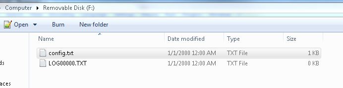
Once you’ve installed the drivers, your Blynk Board should show up on your computer as either COM# (if you’re on a Windows machine) or /dev/tty.usbserial-######## (if you’re on a Mac/Linux computer), where the #’s are unique numbers or alphabetic characters.
Download, Run, and Configure the Terminal
There are a huge variety of software serial terminals out there. If you don’t already have one, read through our Serial Terminal Basics tutorial for some suggestions.
Download a Terminal
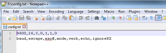
Once you’ve selected terminal software – and found your Blynk Board’s serial port number – open it and set the baud rate to 9600. The Serial Terminal Basics tutorial linked above should have directions for configuring the serial port.
![serial terminal settings]()
Using TeraTerm to communicate with the Blynk Board over a serial interface.
Don’t be alarmed if your Blynk Board resets when you open the terminal. It may also print some debug messages as it re-connects – they’re handy, but nothing you’ll really need to concern yourself with.
Once the port is open, swap back over to your Blynk project. Time to install another terminal!
Blynk Setup
Just one widget this time: the Terminal. We’ll be using the Terminal widget for the rest of this tutorial, so make it cozy, and don’t delete it.
Add a Terminal Widget
Find the terminal widget under the “Displays” list of the widget box.
Once added, tap the terminal to enter the settings screen. Set the terminal widet’s pin to V21. Keep “Input Line” and “Auto Scroll” set to ON.
![Terminal widget settings]()
Pick any screen and background color you please – how about green background and black text, to get a little oppo-matrix style going.
That’s it. Now run the project.
Blynk Run
Try typing something in your computer terminal – you should see those same characters almost instantly pop up on your Blynk project’s terminal.
![Computer terminal example]()
Computer terminal example - text sent by the Blynk Board/App.
Then try typing something into the Blynk terminal. They should show up on your computer.
![Who's on first?]()
The Blynk Terminal has the full transcript of our confusing conversation.
Now have a conversation with yourself! Or share the project and chat with a friend.
For over ten years now, Twitter has been the microblog-of-choice for human and machine alike. While the rich-and-famous use-and-abuse twitter to reach their millions of followers, twitter-enabled projects like our old Kegerator or bots like Stupidcounter have found their own use for the service.
Blynk’s Twitter widget is one of three notification-enabling devices in the app. After connecting it to a Twitter account, the widget will give your Blynk Board a voice on the world-wide-web.
![Tweeting plant project]()
This project, inspired by the Botanicalls Kit, will set your Blynk Board up as a fully-configurable plant soil moisture monitor. Plugged into your favorite house plant, the Blynk Board will give it a voice – so it can shout to the world when it’s thirsty.
Hardware Setup
Our handy Soil Moisture Sensor will be the hardware focus of this experiment.
Out of stock
SEN-13322
The SparkFun Soil Moisture Sensor is a simple breakout for measuring the moisture in soil and similar materials. The soil moi…
2At its core, this two-probed sensor is simply a resistance sensor. Wet soil is less resistive than dry soil, so a parched, dry plant will produce a lower voltage than a wet, sated one.
In addition to the soil moisture sensor, you’ll need jumper wires, alligator clip cables, and a screwdriver
Note that while the Soil Moisture Sensor included with the IoT Starter Kit has a screw terminal installed, the stand-alone product does not.
If you've bought the Soil Moisture Sensor separately, you will need to solder wires or a connector to the board.
Hook Up The Soil Moisture Sensor
There are a few hoops to jump through to get the moisture sensor connected to your Blynk Board. To begin, grab a screwdriver, and three jumper wires – black, red, and yellow.
Flip the board over to see the terminal labels. Plug the yellow wire into the “SIG” terminal, black wire into “GND”, and red into “VCC”. Use the small flathead screwdriver bit to securely tighten the jumper wires into the connector.
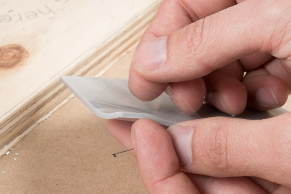
The SparkFun Pocket Screwdriver includes half-a-dozen bits – small/large, flat/Phillips – but they're hidden in the cap. To access the bits, unscrew the cap and pour them out. Look for the smallest flathead you can find in there and slot it into the head.
Once the jumper wires are secured, clamp alligator clip cables onto the other ends – match up the colors if you can!
![Moisture sensor hookup]()
Finally, clamp the other ends of the alligator clips to 3.3V (VCC/red), GND (GND/black), and the ADC (SIG/yellow).
The higher the reading on the ADC, the wetter (and happier) your plant is.
Blynk Setup
This project requires five widgets: Twitter, Terminal, a Value, and two Sliders. Hopefully you’ve got the Terminal – and maybe a few others – from previous projects. Here’s how to set them up:
Set Up the Twitter Widget
Add the Twitter widget from the “Notifications” list. Move it anywhere you’d like, and tap it to configure.
Hit Connect Twitter, and the app will take you to a foreign screen, where you can log in to your Twitter account. This is an OAUTH connection from Blynk to your Twitter account – if you ever want to disconnect Blynk from your account, you can do so in the Apps section of your account settings.
![Connected to Twitter]()
Once you’ve logged in, and allowed Blynk access to your account, the Twitter widget should have a @YOUR_ACCOUNT link in the settings page. Confirm the settings, and head back to the project.
Set Up the Terminal
As with the previous project, the Terminal should be connected to V21, make sure “Input Line” is turned ON.
![Terminal widget settings]()
Give the terminal any color(s) you’d like.
Set Up the Sliders
A pair of sliders are used to set your plant’s moisture threshold and the minimum tweet rate. Add, or re-configure two sliders (large or regular) as so:
| Widget | Name | Pin | Minimum | Maximum |
|---|
| Slider | Moisture Threshold | V23 | 0 | 1023 |
| Slider | Minimum Tweet Rate | V24 | 5 | 60 |
![Threshold slider settings]()
![Tweet rate slider settings]()
The minimum tweet rate slider sets the minimum number of minutes between tweets. The Twitter widget can’t tweet more often than once-a-minute, so make sure that’s the bare-minimum of the slider. Set the maximum to as long as you’d like between tweets (e.g. 60 minutes, 720 minutes [12 hours], etc.)
If the reading out of the soil moisture sensor falls below the minimum threshold, it will begin tweeting as often as it’s allowed (by the tweet rate), until the reading goes back up.
Set up the Value
Finally, add or re-configure a value widget to monitor the ADC pin. You’ll need that as you hone in on a good threshold value.
![Value widget on ADC]()
Blynk Run
Once you’ve got all of those widgets set up, run the project. Plug your moisture sensor into your plant, and check the ADC reading.
![Project setup]()
If your soil is nice-and-moist, the reading should be somewhere around 700-800. Try watering your plant – see if the reading goes up.
To verify that the project is functioning and tweeting, set the threshold to 1023 and set the tweet limit to 1. Within a minute-or-so, you should see a new tweet on your timeline.
![Example tweet]()
So far, so good. Now the tricky part. You need to set the moisture threshold to a “dry soil” value. It’ll be under the current value a bit. If you’re moisture is reading out at about 750, try setting the threshold to 740. Then you play the waiting game (or take a heaterizer to your plant’s soil). When the soil dries up, your plant should tweet.
Why is there an ugly [2341584] at the bottom of every tweet? Twitter rules require that no user can send the same content in a recent tweet. So, just in case you're tweeting every minute, and the moisture hasn't really changed, we've added a "counter" to the bottom of the tweet. That should keep the message unique.
Going Further: Setting the Plant’s Name
Why the terminal? To name your plant! Come up with a unique, identifiable name for your plant. Then, in the terminal, type $MY_PLANTS_TWITTER_NAME and hit enter. Make sure to type the “$” first, the terminal will catch that, and begin tweeting with your new name next time your plant gets thirsty.
![Naming the board in terminal]()
Now when your plant tweets, it’ll identify which one it is.
Project 13: Push Door, Push Phone
Push notifications: you either love them or hate them (or it varies, depending on the app sending them), but they can come in handy every once-in-a-while. The Blynk Push widget allows your Blynk Board to send your phone periodic push notifications, so you’re the first to be made aware of a state change in the board.
This project combines a Door Switch Sensor with the push widget. When the door’s state changes – whether it opens or closes – you’ll be the first…well…at least the second to know!
Hardware Setup
This project is based around a Magnetic Door Switch– a truly magical door-state sensor.
27 available
COM-13247
This is the Magnetic Door Switch Set, a small reed switch assembly specifically designed to alert you when doors, drawers, or…
This door switch is what we call a reed switch– a magnetically-actuated electronic switch. There are two components to the device: the switch itself, and a simple magnet. When the two components are in close proximity, the switch closes. And when they’re pulled far enough apart, the switch opens up. These switches are commonly used as part of a burglar alarm system or as a proximity-detecting device.
Wire Up the Door Switch
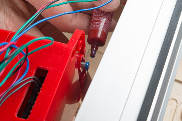
To connect the door switch to your Blynk Board, you’ll just need a couple alligator clip cables – how about red and green. Clamp a red wire to one of the switch’s wires, and the green wire to the other.
![Door switch wired]()
Then clamp the other end of the red wire to 3.3V and the green wire to 16.
We’ve got a pull-down resistor on pin 16. So when the switch is open, it reads as LOW, but when the switch closes the pin connects directly to 3.3V and reads as HIGH.
Blynk Setup
This project uses three widgets: Push (of course), Terminal, and Value. Here’s how to set them up:
Add the Push Widget
You’ll find the Push widget under the “Notifications” list, towards the bottom. After adding it, tap it to configure its settings.
![Android push widget settings]()
Notifications work differently in iOS and Android devices. If you’re using an Android device, your settings will look like above. You can turn the “Notify when hardware goes offline” setting on or off at your discretion – it can be handy in other projects. The Priority setting can be set to HIGH, but it will end up draining your phone’s battery a little faster.
The iOS settings look like this:
![iOS Push settings]()
Again, both of these sliders are left to your discretion. Enabling background notifications will likely take a bit more battery-life out of your phone.
Configure the Terminal
If you’ve still got the Terminal widget from previous projects, great – leave it be. If not, configure it to use pin V21.
![Terminal settings]()
Configure the Value Widget
Finally, set the value widget to V25. This widget will display the up-to-date state of your door switch sensor.
![Value settings]()
Blynk Run
Once everything’s added, run the project! Try putting the two door switches close together, or pulling them apart. A few things should happen:
- The Terminal will print a debug message – stating that the door opened or closed.
- The Value widget should display the up-to-date state of the door.
![Notified!]()
And! Hopefully, your phone will pop up a notification that the switch’s state changed. Unfortunately (or fortunately, depending on how much you enjoy notifications), the Blynk app limits project notifications to once-a-minute. If you open and close the door to fast, you might get the first notification, but for the next minute you’ll need to check the terminal or value widgets.
As with the previous project, you can set the name of your board by typing $BOARD_NAME. That name will be added to the notification that pops up on your phone.
Going Further
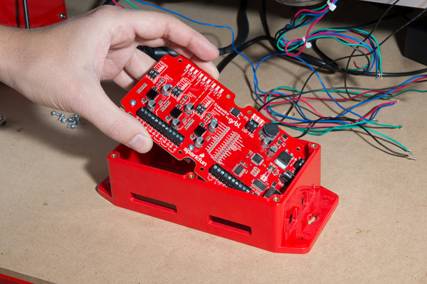
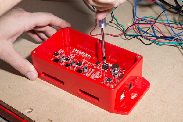
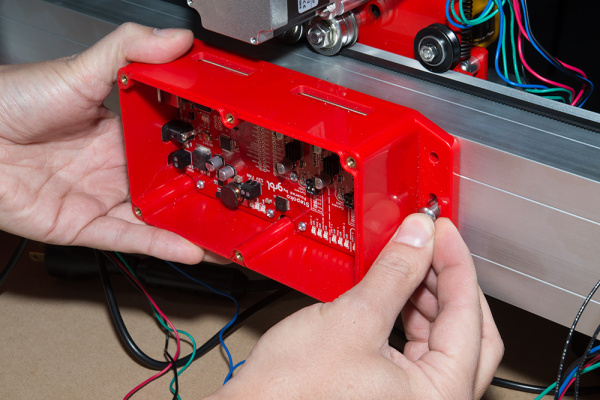
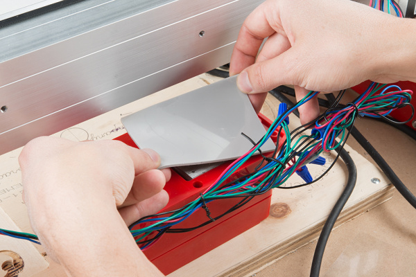
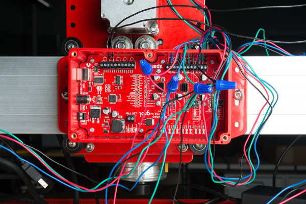
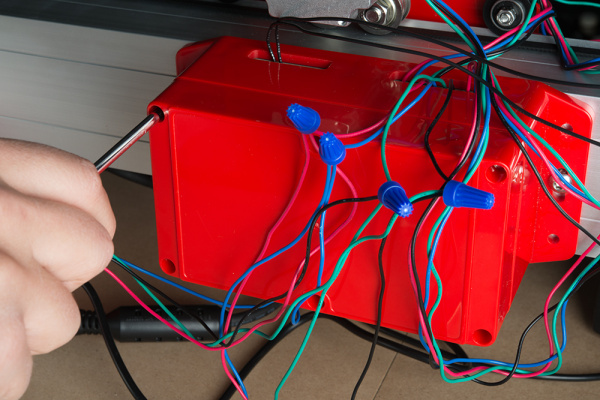
Tape or screw the door switch sensor to something! If you’ve got the IoT Starter Kit, you may already have something to test it out on.
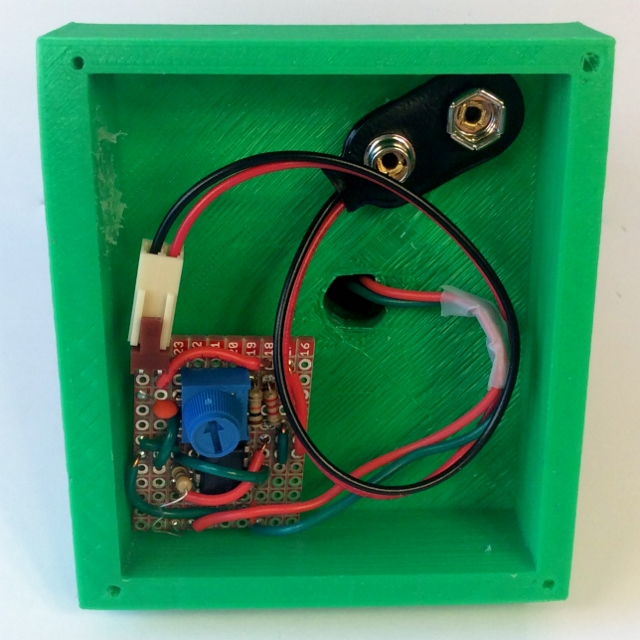
![Using the SparkFun Box to test a door switch]()
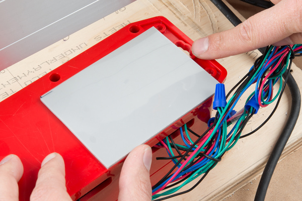
The unique red SparkFun box has been re-purposed as a project enclosure in countless projects. Or you can use it to store your valuables.
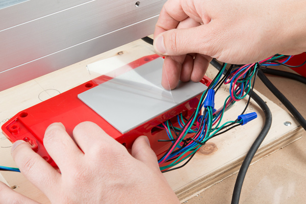
![SparkFun Box closed, valuables safe!]()
With a Blynk-enabled alarm – you’ll be notified whenever someone’s sneaking into your box!
Project 14: Status Emails
The final notification-creating Blynk gadget is the Email widget, which allows you to tailor an Email’s subject and message, and send it to anyone’s inbox. It’s a great power; use it responsibly. Don’t go creating a Blynking spam bot!
![Email widget]()
This project gathers data from all of the sensor’s we’ve been using in these projects, combines them into an Email message, and sends that message to an Email address of your choice (set using the Terminal widget).
There is no external hardware required for this project. If you had a favorite analog component for the ADC, or want to plug a digital input into pin 16, feel free to alligator-clip at will! Among other values, the readings from those pins will be added to the Email's body.
Blynk Setup
This project uses three widgets: Email, Terminal, and a Button.
Add the Email Widget
Find the Email widget under the “Notifications” list, towards the bottom of the widget box.
![Email "Settings"]()
You’re understandably conditioned to tap the Email widget to configure it, but that’s not necessary this time. The Email widget doesn’t have any settings! All it does is provide your Blynk Board with Email-sending ability.
Configure a Terminal Widget
As with the previous experiments, we’ll be using the Terminal widget as an general-purpose string input/output device. If you’ve still got the Terminal widget from previous projects, great – leave it be. If not, configure it to use pin V21.
![Terminal widget settings]()
Most importantly, the Terminal widget will be used to enter an Email address, otherwise the Blynk Board will have nowhere to send your data.
Connect a Button to V27
Finally, we’ll use a button to trigger the sending of an Email. Add or reconfigure a button to activate V27. Make sure it’s a Push button.
![Button widget settings]()
Blynk Run
After running the project, tap into the Terminal input box. Type an exclamation point (!), then type your (or a friend’s) email address. Hit enter, and the Blynk Board should respond with a message verifying the email address you entered.
![Emails sent]()
Now all that’s left is to tap the “Send Email!” button, and check your inbox. A status update should be dispatched to your inbox.
![Example emails]()
Don’t go mashing on the “Send Email!” button, now. The Email widget is limited to sending at most one email a minute. If you’re too trigger-happy, the Terminal will let you know when you can next send an email.
Resources & Going Further
Finished all the projects? Wondering where you go from here? Now that you’re a professional Blynker, consider re-programming the Blynk Board to create a unique project of your own! Check out our Programming the Blynk Board in Arduino tutorial to find out how to level up your Blynking!
Or, if you’re looking for more general Blynk Board or Blynk App resources, these may help:
- SparkFun Blynk Board Resources
- Blynk Resources
If you need any technical assistance with your Blynk Board, don’t hesitate to contact our technical support team via either e-mail, chat, or phone.
learn.sparkfun.com |CC BY-SA 3.0
| SparkFun Electronics | Niwot, Colorado