Introduction
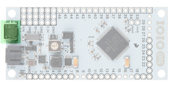
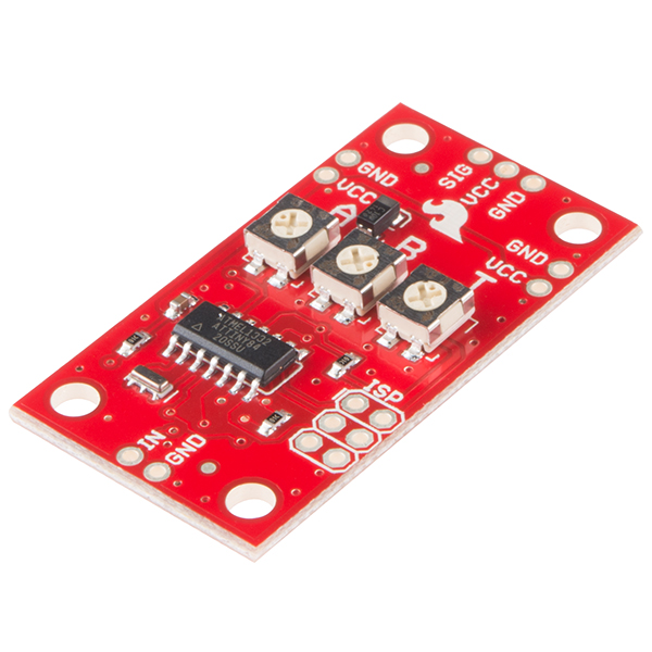
The IOIO-OTG (pronounced “yo-yo-O-T-G"; the OTG stands for On-The-Go) is a development board specially designed to allow developers to add advanced hardware I/O capabilities to their Android or PC application. It features a PIC microcontroller, which acts like a bridge that connects an app on your PC or Android device to low-level peripherals like GPIO, PWM, ADC, I2C, SPI and UART. An app-level library helps you write control code for these low level peripherals in the same way you’d write any other Java app!
![IOIO-OTG]()
What separates the IOIO-OTG from previous IOIO boards is its ability to leverage the USB On-The-Go specification to connect as a host or an accessory. There are several ways to connect the IOIO to your Java app. If the app is running on your Android device, the IOIO-OTG will act as a USB host and supply charging current to your device (meaning the IOIO-OTG will need its own power source). If your app is running on a Windows, Linux or OSX machine, the IOIO-OTG will assume device mode and present itself as a virtual serial port. When in device mode, the IOIO-OTG can be powered by the host. Connecting a USB Bluetooth® dongle will cause the IOIO-OTG to show up as a Bluetooth serial connection, so you can go wireless!
Required Materials
A USB Female A to Micro A OTG Cable should have been included with the purchase of your IOIO-OTG.
In addition to the IOIO and this cable you will need these items to follow along with this tutorial.
Suggested Reading
While not covered in this tutorial directly, the IOIO-OTG is capable of the functions mentioned below. Should you find any of them unfamiliar, take a detour over to that tutorial, then head on back here when finished.
You should have a good understanding of using the Command Line before getting started with the IOIO-OTG.
IOIO Board Overview
This section will cover the various parts and features found on the IOIO-OTG board.
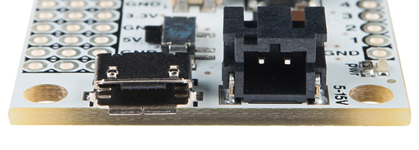
USB Micro-AB Connector
![MicroAB]()
The micro USB connector is used to connect the IOIO to a number of devices. You can connect the IOIO to a PC using a micro-B USB Cable. The supplied USB Female A to micro-A OTG Cable should be used whenever connecting to an Android device, with the IOIO acting as host (for charging the Android), OR to a Bluetooth dongle.
Please Note: This connector is a USB micro-AB connector, which means it can accept both USB micro-A and USB micro-B connections.
![closeup]()
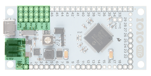
Power
![power]()
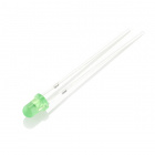
Power LED
In the bottom-left corner of the image, we have the red power LED. This illuminates when the IOIO is powered through either the USB port, the JST connector or the VIN pins.
2-pin JST Female Power Jack
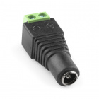
Used for power supply to the board. Voltage between 5V–15V should be supplied. The simplest way to power the IOIO-OTG is to use a wall power supply (5–15V) coupled with our Barrel Jack to JST adapter. Consider a supply that is 1.5V+ higher than 5V. This will result in a more stable 5V supply coming from the voltage regulator.
VIN pins (3 pins)
Used for outputting the supply voltage to your circuit, or as an alternative input to the power jack.
5V Pins (3 pins)
5V output from the onboard regulator, which can be used in your circuit.
3.3V Pins (3 pins)
3.3V output from the onboard regulator, which can be used in your circuit.
You can read more about ways to power the IOIO-OTG here.
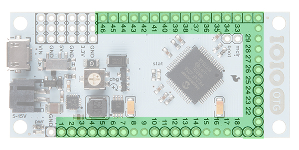
GPIO Pins
![GPIO]()
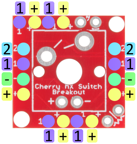
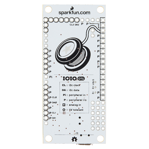
General Purpose Input/Output (GPIO) pins are the meat of the IOIO-OTG and are the pins used to interface your applications to the physical world. There’s a lot going on here and many variations amongst these pins. Luckily, there is a handy key located on the back of the IOIO to clarify which pins are capable of which functionality.
![back]()
To clarify, the key is as follows:
- Pins with Black Circles around them can be used as 5V Tolerant I/O. Pins without circles should only be used with 3.3V devices.
- Pins with Black Squares can be used as Analog Inputs.
- Pins marked with a ‘P’ can be used as Peripheral Inputs/Outputs.
- Pins marked with a ‘Pi’ can be used as Peripheral Inputs only.
- Pins marked with CL or DA can be used as the Clock and Data lines for the various I2C ports on the IOIO. There are three I2C ports available on the IOIO-OTG.
By default, pins might be damaged if exposed to voltage outside the 0V-3.3V range. 5V-tolerant pins extend this range to 0V-5V, thus allowing us to communicate with 5V logic.
You can read more about the IOIO-OTG’s I/O pins here.
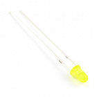
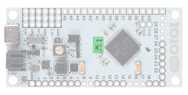
Status LED
![statLED]()
Normally, this yellow LED is under application control (“pin 0”). In very few special cases (e.g., bootloader mode), it has a special meaning (to indicate entry into bootloader mode or an unconfigured oscillator).
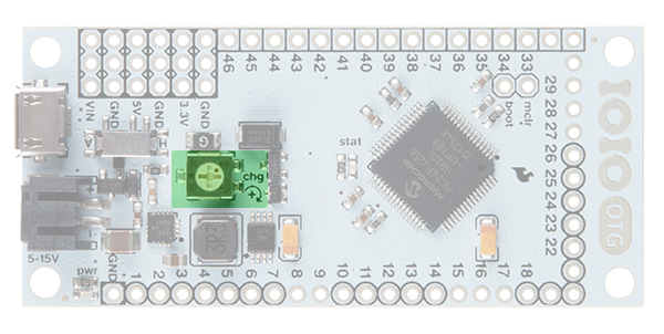
Charge Current Trimpot (CHG)
![trimpot]()
The CHG adjusts the amount of current supplied on the VBUS line of the USB when acting as a USB host (or when it is connected to your Android). It is typically used in battery-powered applications to prevent battery drain. Turning in the clockwise (+) direction increases charge current. Generally, this can be left at the default factory setting, which is fully clockwise.
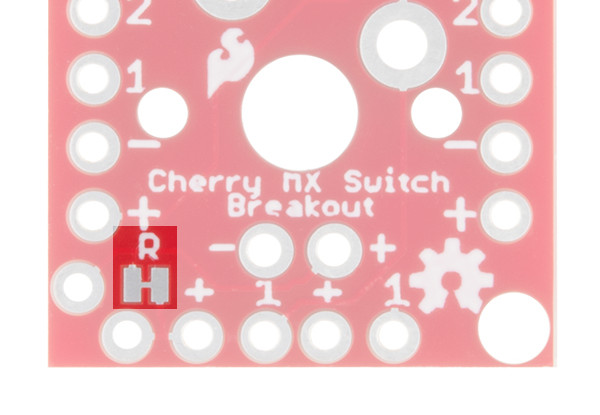
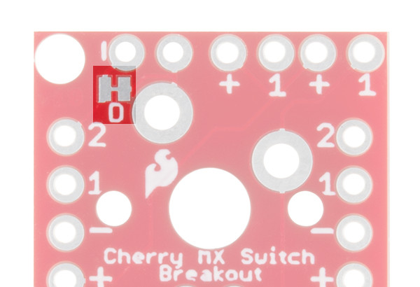
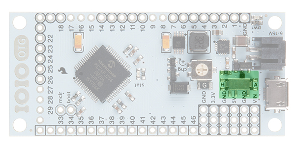
Host/Device Switch
![switch]()
Not normally used. Keep switch in A mode. In “A” mode, the IOIO-OTG will detect whether it should act as host or as device automatically, according to whichever USB connector is plugged in (micro-A or micro-B). The only reason to put it in H mode is when working with a non-standard USB-OTG cable or adapter that doesn’t identify itself correctly on the host side or the cable. This should never be the case with the provided USB-OTG cable.
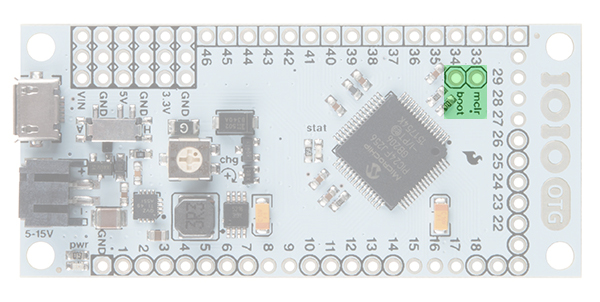
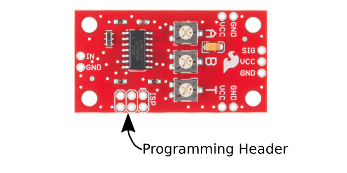
MCLR and Boot Pins
![mclr and boot pins]()
MCLR
This pin will only be used on occasion by the user for firmware upgrades. This pin is for programming a new bootloader onto the IOIO-OTG board.
BOOT
This pin will only be used on occasion by the user for firmware upgrades. This pin is used to switch the IOIO-OTG into bootloader mode on power-up. Note that this pin is shared with the Stat LED.
More information about the IOIO-OTG hardware can be found here.
Software Downloads and Installation
This section will cover the installation of all the software necessary to get started with the IOIO-OTG. All of these pieces of software will be used throughout the tutorial, though not all of them will be used in each example. If you only wish to use your PC to develop on the IOIO or, alternatively, only want to develop on an Android device/emulator, you may only need to install the software for those specific applications.
Set Aside Some Time: Installing all of these pieces of software at once will be time-consuming. Set aside 30-60 minutes, depending on your computer's speed and internet connection.
Client Software and IOIO Application Firmware
Head over to the Downloads section of the IOIO wiki on GitHub. Scroll down until you see the section titled Client Software and IOIO Application Firmware Images. Under the Client-side Software column, download the latest version, which will be delivered as a .zip file (App-IOIOxxxx, where xxxx is the software/library version number). Unzip it, and place that folder in a location of your choosing (we recommend your home directory). Remember the location, as it will be used frequently throughout this tutorial. You can also download it directly from the link below.
IOIO Library and Examples
This folder contains all the Client-side software for the IOIO, including the IOIO Library and the examples we will be using both on a PC and on an Android device/emulator. These files will be necessary to get started with the IOIO no matter which method you choose for development.
No further action is needed after downloading and unzipping this folder.
Note: If you are using an older IOIO board, make sure the version number of your IOIO Library is less than or equal to the version number of your firmware.
IOIO Bridge
Another piece of software we’ll need from the IOIO GitHub wiki is IOIO Bridge, which can be found under the Tools section. Or, you can download it directly using the link below.
IOIO Bridge
This tool allows you to have your Android device and your IOIO plugged into your computer at the same time, allowing for faster development.
No further action is needed after downloading and unzipping this folder.
IOIO Device Driver
To use the IOIO-OTG with your personal computer, download and install the device driver for the IOIO. You may need to plug the IOIO-OTG into your computer to complete the driver installation.
Windows
Provide this file (right-click, and choose Save Link As…) to the “Add Hardware” wizard on your Windows machine.
Linux
Copy this udev rules file to the udev rules directory. More information can be found here.
OSX
No driver installation is necessary if using the Mac OS.
You can find more information about interfacing your IOIO with your PC over on the IOIO wiki.
Java Development Kit (JDK)
Whether you’re developing with the PC, an Android device or both, it’s necessary to have Java installed. If it’s not installed already, you can find it on Oracle’s website. Choose the correct file for your OS.
While it’s only necessary to have the Java Runtime Environment (JRE) installed, you may find it easier to just install the entire Java Development Kit (JDK). The version of Java pointed to by your command line may be an outdated version. Installing the latest version of the JDK will update all references to Java your system may need.
Note that your OS may come with Java already installed. You can check by typing java -version into your command line window on any OS. This command will also let you know if the installation from above was successful.
Android Studio and Android SDK
To create your own Android apps or to use existing Android app examples, you will need to have Android Studio installed. If you wish to work exclusively on your PC, you do not need to install Android Studio. If needed, download it from the link below.
Android Studio and Android SDK
Once downloaded, follow the appropriate instructions for your OS, and install it as you would with other applications. Remember its location for later use.
Follow the setup wizard. You will eventually reach a page verifying all the installation settings to be installed. Take note of where the SDK Folder is, as it will be needed following installation.
![alt text]()
We will need to use the Command line in conjunction with Android Studio. You will most likely need to add the Android SDK platform-tools folder to your $PATH, which can be found in the SDK Folder mentioned previously.
Windows users can find GUI $PATH instructions here. Command line instructions can be found here. The command should look something like this:
PATH %PATH%;~/Android/sdk/platform-tools/
Mac and Linux users can find $PATH instructions here. The command should look something like this:
export PATH=$PATH:~/Library/Android/sdk/platform-tools/
In the Command line, type adb, which stands for Android Debug Bridge. If you see a list of adb commands print out, the installation and $PATH update was a success!
Gradle
Gradle is an open source build automation system used to compile Java code. We will be using this to build our own PC application for the IOIO. Android Studio comes with a copy of Gradle, so, if you wish to skip the PC app sections and move straight to the Android app sections, you do not need to install this separately.
Download Gradle here. You can grab the Binary only distribution.
You will most likely need to add the Gradle bin folder to your $PATH.
Windows users can find GUI $PATH instructions here. Command line instructions can be found here. The command should look something like this:
PATH %PATH%;~/gradle-2.12/bin/
Mac users can find $PATH instructions here. The command should look something like this:
export PATH=$PATH:~/gradle-2.12/bin/
You can check to see if it worked by typing gradle -v. You should see some version info print out.
![gradle version]()
Running Your First PC App
We will begin by running a PC application from the App-IOIOxxxx folder downloaded from the IOIO GitHub repo. Download it now, if you have not done so already. Using this known-good application will help to ensure everything is working correctly, both on the hardware and software side.
Plug the IOIO into Your PC
Using a micro USB cable, plug the IOIO-OTG into your computer’s USB port. You should see the red power LED illuminate. No other connections are necessary at this time.
Find the IOIO’s Serial Port
Next, find the IOIO’s serial port so we can communicate with it through the command line. Install the drivers mentioned in the Software Installation section, if you have not done so already.
On Mac OSX or Linux, open the Command Line Interface (CLI) of your choice and type:
ls /dev/tty.*
You should see the IOIO appear as tty.usbmodemXXXX, where the X’s are some specific characters and numbers.
On Windows, open the Device Manager, and check to see which COM Port the IOIO has enumerated as under the ports section. The IOIO will appear as COMXX, where the X’s are a specific number.
Take note of this, as we will need it shortly.
Navigate to the Pre-Built App
In your command line, navigate to the App-IOIOxxxx folder. Then cd into the bin folder. In here, there is a binary file titled HelloIOIOConsole-5.07-standalone.jar. We’re going to run this application from the command line. It will establish a connection with the IOIO and allow you to control the onboard Stat LED from the command line.
To run the app, type the following:
java -Dioio.SerialPorts=YOUR_IOIO_SERIAL_PORT -jar HelloIOIOConsole-5.07-standalone.jar
where YOUR_IOIO_SERIAL_PORT is replaced by the serial port from the previous step.
On Mac and Linux, this will look something like:
java -Dioio.SerialPorts=/dev/tty.usbmodemfd141 -jar HelloIOIOConsole-5.07-standalone.jar
On Windows, this will look something like:
java -Dioio.SerialPorts=COM65 -jar HelloIOIOConsole-5.07-standalone.jar
You should see some information printed to the command line. The most important line is IOIO connection established. If you see that, you’re connected to your IOIO through the command line!
Now, press enter. You should see some instructions print to the screen.
Unknown input. t=toggle, n=on, f=off, q=quit.
Press t + ENTER. You should see the stat LED turn on. Press t + ENTER again, and it should turn off. You are now controlling your IOIO from your PC! Try using the other commands.
You have just run your first IOIO PC application!
If you are having trouble getting the app to work, please visit the Troubleshooting section.
Building Your First PC App
In the previous section, we ran a pre-built PC application. In this section we will use that same application’s code to learn how to build/compile our own PC application (.jar file) for the IOIO.
Download Gradle
To begin, we need to first download Gradle to compile the code. Gradle is an open source build automation system used to compile code – Java in this case.
Download Gradle here, if you have not done so already. You can grab the Binary only distribution.
Extract the .zip file, and place it somewhere you’ll remember. It’s recommended you place it in your home directory.
You will most likely need to add the Gradle bin folder to your $PATH.
Windows users can find GUI $PATH instructions here. Command line instructions can be found here. The command should look something like this:
PATH %PATH%;~/Android/sdk/platform-tools/
Mac users can find $PATH instructions here. The command should look something like this:
export PATH=$PATH:~/gradle-2.12/bin/
You can check to see if it worked by typing gradle -v. You should see some version info print out.
![gradle version]()
Looking at the Code
In the command line, navigate to the App-IOIOxxxx folder you downloaded from GitHub previously. Then cd to the /src/applications/pc directory. Here you will find all the PC applications and all their source code. The application we used previously was the HelloIOIOConsole app. From here, continue to navigate to this directory: /HelloIOIOConsole/src/main/java/ioio/examples/hello_console/. In here you’ll find a HelloIOIOConsole.java file. This is the code we want to have a look at. Open this file in vim or your favorite editor. You can copy the line below.
vim /src/applications/pc/HelloIOIOConsole/src/main/java/ioio/examples/hello_console/HelloIOIOConsole.java
You can also navigate to that folder from your file explorer and open the file in your favorite code viewer.
The code you see should look like the code below:
language:java
1 package ioio.examples.hello_console;
2
3 import java.io.BufferedReader;
4 import java.io.IOException;
5 import java.io.InputStreamReader;
6
7 import ioio.lib.api.DigitalOutput;
8 import ioio.lib.api.IOIO;
9 import ioio.lib.api.exception.ConnectionLostException;
10 import ioio.lib.util.BaseIOIOLooper;
11 import ioio.lib.util.IOIOConnectionManager.Thread;
12 import ioio.lib.util.IOIOLooper;
13 import ioio.lib.util.pc.IOIOConsoleApp;
14
15 public class HelloIOIOConsole extends IOIOConsoleApp {
16         private boolean ledOn_ = false;
17
18         // Boilerplate main(). Copy-paste this code into any IOIOapplication.
19         public static void main(String[] args) throws Exception {
20                 new HelloIOIOConsole().go(args);
21         }
22
23         @Override
24         protected void run(String[] args) throws IOException {
25                 BufferedReader reader = new BufferedReader(new InputStreamReader(
26                                 System.in));
27                 boolean abort = false;
28                 String line;
29                 while (!abort && (line = reader.readLine()) != null) {
30                         if (line.equals("t")) {
31                                 ledOn_ = !ledOn_;
32                         } else if (line.equals("n")) {
33                                 ledOn_ = true;
34                         } else if (line.equals("f")) {
35                                 ledOn_ = false;
36                         } else if (line.equals("q")) {
37                                 abort = true;
38                         } else {
39                                 System.out
40                                          .println("Unknown input. t=toggle, n=on, f=off, q=quit.");
41                         }
42                 }
43         }
44
45         @Override
46         public IOIOLooper createIOIOLooper(String connectionType, Object extra) {
47                 return new BaseIOIOLooper() {
48                         private DigitalOutput led_;
49
50                         @Override
51                         protected void setup() throws ConnectionLostException,
52                                         InterruptedException {
53                                 led_ = ioio_.openDigitalOutput(IOIO.LED_PIN, true);
54                         }
55
56                         @Override
57                         public void loop() throws ConnectionLostException,
58                                         InterruptedException {
59                                 led_.write(!ledOn_);
60                                 Thread.sleep(10);
61                         }
62                 };
63         }
64 }
If you have programmed Arduinos or other microcontrollers before, you will see some familiar lines of code. Starting on line 16, we have a variable called ledOn_. This boolean holds the state of the LED, true or false for high or low.
Following that, we have the run() function on line 24. Then you can see the if and if/else statements that control the state of the LED based on the input received in the Command line.
Next, on line 51, there’s the void setup() function and the void loop() function on line 57, with which you may be familiar. Inside the setup() function on line 53, there is the led_ variable that is set to IOIO.LED_PIN. This is telling the code to use the IOIO’s onboard Stat LED, “pin 0.”
Last, in the loop() function on line 59, there is the led_.write() function that alters the state of the Stat LED, !ledOn_, when the appropriate characters are received from user input. The Thread.sleep(10); is just a delay, having the loop check every 10ms.
Compile the Code
Now that we have a better understanding of what’s happening in the code, it’s time to build our own executable .jar file that will allow us to run this PC app on the IOIO.
To compile the code, change directories back to:
/src/applications/pc/HelloIOIOConsole
In this directory, you will see the src folder we were just exploring and a build.gradle file. If you would like, you may open the build.gradle file in your favorite editor to see how the compiler works. Going into those details is beyond the scope of this tutorial.
Type gradle build. You should see some info print out followed by BUILD SUCCESSFUL.
![gradle build]()
Run the Application
Type ls once the compilation is complete. You should now see a folder titled build. Inside that build folder is the .jar app we intend to run on the IOIO. Navigate to:
cd build/libs
Here, you should see two .jar files. The one titled HelloIOIOConsole-standalone.jar is the one we’re after.
![jar file]()
Connect the IOIO to the PC if it isn’t connected already.
Back in your Command line, type the following to run the app. Don’t forget to change YOUR_IOIO_SERIAL_PORT to the port to which your IOIO is connected, as mentioned in the previous section.
java -Dioio.SerialPorts=YOUR_IOIO_SERIAL_PORT -jar HelloIOIOConsole-standalone.jar
As in the previous section, you should see some info print out followed by IOIO connection established. You can now control the IOIO Stat LED just as before, typing t + ENTER to toggle its state.
Congratulations, you just built your first Java app for the IOIO!
From here, you can use this code as a base to start exploring the IOIO’s capabilities. Change or add a few lines of code, compile with Gradle, and see what happens!
For a complete list of all the commands you can issue to the IOIO, go back to the IOIO folder you downloaded from GitHub. Inside that folder is another folder titled doc. Navigate to doc, and open the index.html file in your browser. There you will find a reference of all the IOIO classes. See if you can get an LED to blink on one of the IOIO’s digital I/O pins.
Check the Resources and Going Further section for more information and links to IOIO resources.
If you are having trouble getting the app to work, please visit the Troubleshooting section.
Running Your First Android App
We will transition from using the PC to using an Android device or emulator to run apps created for the IOIO.
Download Android Studio
If you have not done so already, you will need to download and install Android Studio.
Once downloaded, follow the appropriate instructions for your OS, and install it as you would with other applications. Remember its location for later use.
Follow the setup wizard. You will eventually reach a page verifying all the installation settings to be installed. Take note of where the SDK Folder is, as it will be needed following installation.
![alt text]()
We will need to use the Command line in conjunction with Android Studio. You will most likely need to add the Android SDK platform-tools folder to your $PATH, which can be found in the SDK Folder mentioned previously.
Windows users can find GUI $PATH instructions here. Command line instructions can be found here. The command should look something like this:
PATH %PATH%;~/Android/sdk/platform-tools/
Mac user can find $PATH instructions here. The command should look something like this:
export PATH=$PATH:~/Library/Android/sdk/platform-tools/
In the command line, type adb, which stands for Android Debug Bridge. If you see a list of adb commands print out, the installation was a success!
Plug in Your Android Device to Your PC
Before plugging your Android device into your PC, you’ll need to first turn on USB Debugging. To do so, navigate to your device’s Settings and under the System heading click on Developer options. Then, under Debugging, make sure the USB Debugging check box is checked.
Heads up! When switching from having your Android device plugged into your PC and having the IOIO plugged into your device, you will need to constantly turn on and off USB Debugging. Don't fret, though; we'll show you a way around this in the
IOIO Bridge section.
With USB Debugging enabled, you can now plug your Android device into your PC. Once plugged in, you can check to see if your device is showing up in the command line with the following command:
adb devices
You should see your device’s info print out after the List of devices attached line.
Note: If you have not plugged your device into your PC before, you'll need to wait for the PC to finish installing the device drivers before it will show up using the adb devices command.
Check for any prompts on your Android device before continuing. Your device may ask to allow USB Debugging for this computer. Click OK, and check the ‘Always allow from this computer’ check box, if you desire.
![Debugging]()
Upload App to Android Device
With your device connected to your PC, navigate to the bin folder in the App-IOIOxxxx folder via the Command line. In this folder is a pre-compiled app (.apk file) titled HelloIOIO-debug-unaligned.apk. Upload this app to your device using the following command:
adb install HelloIOIO-debug-unaligned.apk
You should see the following success message print out:
![success]()
On your Android device, navigate to your applications. You should now see a HelloIOIO app on your device.
![app]()
Plug in the IOIO to your Android Device
Heads up! Be sure to disable USB Debugging before you plug your IOIO into your Android device.
Unplug your device from the PC, keeping the micro USB cable attached to your Android device. Attach the red USB Female A to micro-A OTG Cable to the end of the micro USB cable. Then attach the micro-A end of the OTG cable to the micro-AB connector on the IOIO-OTG.
Provide power to your IOIO using the Barrel Jack-to-JST Adapter. The red power LED should illuminate.
![alt text]()
Open the HelloIOIO app. Your device may ask you if you want to automatically open that app when the IOIO is plugged in. You will be presented with this screen:
![app]()
Press the button on the touchscreen to turn the Stat LED on and off. You’ve just uploaded and successfully used your first IOIO Android application!
![alt text]()
If you are having trouble getting the app to work, please visit the Troubleshooting section.
Building Your First Android App
Now that we know how to upload a known-good application, let’s see what it takes to build our own using Android Studio.
Open Android Studio
Note: Going into detail about how to use Android Studio is beyond the scope of this tutorial. This section will minimally cover how to upload an app using this software. For more information on getting started with Android Studio, we suggest you complete their
Building Your First App tutorial.
Open Android Studio. If this is the first time you’re opening it, it may take a few minutes. There may be several setup/first-time-tips windows to navigate through.
You should eventually be presented with the following screen asking what action you’d like to perform:
![alt text]()
Choose ‘Open an existing Android Studio project.’
Open HelloIOIO Application
Inside the Android Studio file explorer window, navigate to ~/App-IOIO0507/src/applications, and open the folder titled HelloIOIO.
![alt text]()
Heads up! Upon opening the project, Android Studio may yell at you about there being mismatched versions of various pieces needed to compile the code, such as the Android SDK or the Gradle Wrapper. It will offer downloads of the version(s) needed to correct the mismatch.
![]()
![]()
Keep clicking OK and installing any missing platforms until Android Studio is happy.
![]()
The project tree has many files. The file that contains the Java code for the IOIO is in HelloIOIO→ scr→ ioio.examples.hello→ MainActivity.java. Double click on the MainActivity.java file, and you should see this:
![alt text]()
The MainActivity.java file contains the code that talks to the IOIO board. If you want to change the UI (user interface or graphics) of your app, the res → layout → main.xml file is where you make the changes. Here you can start writing code and changing the HelloIOIO sketch, if you desire.
Delete App from Android Device
Though we’ll be installing the same app as in the previous section (unless you decided to alter the code), you will need to uninstall the app on your Android device to ensure that Android Studio is working properly.
Make sure that you are uninstalling the app and not just removing it from your home page. On most devices, this requires long tapping the app and dragging it to the Uninstall (trash bin) area at the top of the screen.
Plug in Your Android Device to Your PC
Plug your Android device into your PC.
Heads up! Be sure to enable USB Debugging before you plug in your Android device.
Upload App to Android Device
With your device connected to your PC, click the ‘Run’ button:
![run]()
Android Studio will ask to which device you’d like to upload the application. Assuming you only have one device plugged in, there should only be one option. You can also use the Android emulator if you do not have an Android device.
![select device]()
You should see the build status at the bottom of the window. It will say Gradle Build Running, followed by Gradle build finsihed.
![build]()
On your Android device, navigate to your applications. You should now see a HelloIOIO app on your device.
![app]()
Plug in the IOIO to Your Android Device
Heads up! Be sure to disable USB Debugging before you plug your IOIO into your Android device.
Unplug your device from the PC, keeping the micro USB cable attached to your Android device. Attach the red USB Female A to Micro A OTG Cable to the end of the micro USB cable. Then attach the micro A end of the OTG cable to the Micro A-B connector on the IOIO-OTG.
Provide power to your IOIO using the Barrel Jack-to-JST Adapter. The red power LED should illuminate.
![alt text]()
Open the HelloIOIO app, and you should be presented with this now familiar screen:
![app]()
Press the button on the touchscreen to turn the Stat LED on and off. You’ve just successfully built, uploaded and used your first IOIO Android application!
![alt text]()
For a complete list of all the commands you can issue to the IOIO, go back to the IOIO folder you downloaded from GitHub. Inside that folder is another folder titled doc. Navigate to doc, and open the index.html file in your browser. There you will find a reference of all the IOIO classes. See if you can get an LED to blink on one of the IOIO’s digital I/O pins.
Check the Resources and Going Further section for more information and links to IOIO resources.
If you are having trouble getting the app to work, please visit the Troubleshooting section.
IOIO Bridge for Development
By now you’ve come to realize how inefficient it can be to have to plug in your device, turn on USB debugging, upload your app, unplug, turn off debugging, plug in the IOIO, test and repeat for every change you want to make. Luckily there’s a tool to help aid in your IOIO/Android development.
Download IOIO Bridge
If you have not done so already, go and download the latest version of IOIO Bridge from the IOIO wiki on GitHub. It can be found under the Tools section. Or, you can download it directly using the link below.
IOIO Bridge
Plug in Android Device and IOIO-OTG to Your PC
Heads up! Be sure to enable USB Debugging before you plug in your Android device.
Using two (2) micro USB cables, plug both your Android device and your IOIO-OTG into your PC.
![connected to PC]()
Find the IOIO’s Serial Port
If you have not done so already, find the IOIO’s serial port so you can communicate with it through the Command line. You may need to install the drivers mentioned in the Software Installation section.
On Mac OSX or Linux, open the Command Line Interface (CLI) of your choice and type:
ls /dev/tty.*
You should see the IOIO appear as tty.usbmodemXXXX, where the X’s are some specific characters and numbers.
On Windows, open the Device Manager, and check to see which COM Port the IOIO has enumerated as under the ports section. The IOIO will appear as COMXX, where the X’s are a specific number.
Take note of this, as we will need it shortly.
Run IOIO Bridge
Navigate to the IOIO Bridge folder, in your Command line, and run the IOIO Bridge executable followed by the IOIO’s serial port.
On Mac and Linux, this will look something like:
./ioiobridge /dev/tty.usbmodemfd141
On Windows, this will look something like:
ioiobridge COM65
You should see a printout stating connections to both devices were successful and the bridge is running.
![bridge running]()
Note: If IOIO Bridge has stalled while waiting to connect to the Android application, you will need to open the HelloIOIO app (or other IOIO app) to establish that connection.
You can now interact with the application, and it should be controlling the IOIO-OTG through IOIO Bridge and your PC! Try pressing the button to control the Stat LED.
You can now upload applications to your device (PC or Android) while leaving it plugged in. Then you can test the IOIO’s behavior right away so long as IOIO Bridge is running. Be sure to turn off IOIO Bridge (Ctrl-C) before uploading a new application and starting it once the app has been uploaded.
Going Wireless with Bluetooth
The last thing we’ll cover is how to make your project wireless using Bluetooth. Going wireless is another method to make development a little easier as you don’t have to connect and disconnect the IOIO every time you want to test changes made to your app.
Bluetooth Dongle
In order to utilize the IOIO’s Bluetooth capabilities, you’ll need to acquire a Bluetooth dongle. Most models of dongles should work with the IOIO-OTG. The dongle below has been tested with the IOIO and works great.
In stock
WRL-09434
This is a handy little Bluetooth USB mini-adapter. This adapter supports Bluetooth v2.0 class 1 and has a maximum distance of…
To connect the dongle, attach it to the larger end of the USB Female A to Micro A OTG Cable, with the other end attached to the IOIO. Then, power the IOIO-OTG with the Barrel Jack-to-JST Adapter.
![alt text]()
Some dongles may have a flashing LED to indicate they are receiving power and awaiting a connection.
Bluetooth Connection
On your Android device, turn Bluetooth on, if it isn’t already. Search for new devices. You should eventually see the IOIO appear. Pair your device with the IOIO.
![alt text]()
When your device asks for the passcode code to pair with the IOIO, enter:
4545
Your device should now be wirelessly connected to the IOIO-OTG.
Open the HelloIOIO app used in the previous examples. Press the button to control the LED over the Bluetooth connection!
You can leave your device plugged in while you develop, all while maintaining the wireless connection with the IOIO.
Troubleshooting
Driver Installation
If your IOIO is not showing up as a serial port, make sure you have installed the drivers from the Software Installation section. Going through the installation process again may solve any issues you may have with your PC communicating with the IOIO-OTG.
Updating Java
Some users may have computers running an outdated version of Java. If you encounter issues, please consider updating to the latest version.
To check which version of Java you are running, run this command in the Command line:
java -version
Download latest version here. Accept the License Agreement, and download the version that matches your OS.
JDK vs JRE
Using on an older MacBook to develop with the IOIO, I found that my Java version was outdated. When just the JRE was installed, it still did not update the version of Java pointed to by my Terminal. I found this Stack Overflow post about the same issue. Downloading the entire JDK solved my issue. However, if you do not wish to download the entire JDK, you can visit that post to see how to tell your Command line which version of Java to use.
USB Debugging
If you are having issues with your Android device not communicating with your IOIO, check the USB Debugging.
Ensure that USB Debugging is ENABLED (checked) when you have your Android device plugged into a computer.
Ensure that USB Debugging is DISABLED (not checked) when you have your IOIO plugged into your Android Device.
Check USB Connections
If the IOIO or your Android device is not communicating with the computer, check the micro USB connections. It’s easy to plug one end of the cable most of the way in, but not quite enough.
Visit the Wiki
There is a plethora of information on IOIO’s GitHub wiki. Visit there for more troubleshooting suggestions.
Contact SparkFun’s Technical Support
If you have any tutorial feedback, please visit the Comments or contact our technical support team at TechSupport@sparkfun.com.
Resources and Going Further
You should now be well on your way to becoming a software and hardware integration master. This tutorial has only scratched the surface of what the IOIO-OTG is capable of. It is now up to you to choose your own adventure and explore what possibilities the IOIO-OTG has in store for you.
Hardware Resources
IOIO-OTG Resources
Android Resources
Looking for inspiration for your next project? Check out these other great SparkFun tutorials:
learn.sparkfun.com |CC BY-SA 3.0
| SparkFun Electronics | Niwot, Colorado