Introduction to the Johnny-Five Inventor's Kit
In stock
KIT-13847
The Johnny-Five Inventor's Kit (J5IK) is your go-to source for developing projects using the Tessel 2 and the Johnny-Five pro…
The Johnny-Five Inventor’s Kit you have in front of you is your toolkit, and this Experiment Guide is your map. We’re going to dive into the world of embedded electronics, JavaScript, the internet, and the way they come together as the “Internet of Things” (IoT). The Johnny-Five JavaScript framework provides a beginner-friendly way to start building things—quickly. This guide contains all the information you need to successfully build the circuits in all 14 experiments. At the center of this guide is one core philosophy: that anyone can (and should) play around with basic electronics and code.
When you’re done with this guide, you’ll have the know-how to start creating your own projects and experiments. You can build robots, automate your home, or log data about the world around you. The world, in fact, will be your hardware-hacking oyster. Enough inspirational sentiment — let’s get building!
Note: To get started with this guide you will need to have an internet connection and administrative privileges on the computer that you are using.
Included Materials
Here are all of the parts in the Johnny-Five Inventor’s Kit for the Tessel 2 (J5IK):
- Tessel 2— The Tessel 2 Single-Board Computer (SBC)
- USB-A to USB micro B— for connecting your computer to the Tessel 2
- Wall Charger (5V, 1A)— Gotta power the Tessel 2 somehow! This charger makes it easy to power your projects!
- Breadboard— This perforated grid is the ticket to easy experimentation with circuits.
- Carrying Case— Take your kit anywhere with ease!
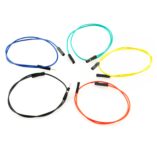
- Jumper wires— These multi-colored wires with pins on each end making connecting things together a breeze.
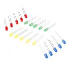
- Rainbow Pack of LEDs— LEDs are indispensable. Here’s a whole rainbow of ‘em.
- 100 Ohm Resistors— These are just about right for using with LEDs at 3.3V (the voltage we’ll be using for the circuits in this guide)
- 10K Ohm Resistors— These make excellent pull-ups, pull-downs and current limiters (don’t worry if you haven’t seen these terms before)
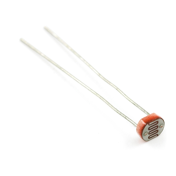
- Photocell— A sensor that detects ambient light. Also called a photoresistor. Perfect for detecting when a drawer is opened or when nighttime approaches.
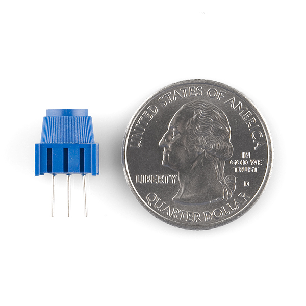
- 10KΩ Trimpots— Also known as a variable resistor or a potentiometer, this is a device commonly used to control volume and contrast (it usually has a dial or a slider), and makes a great general user control input.
- Red, Blue, Yellow and Green Tactile Buttons— These fun-to-press buttons give you several colors to choose from.
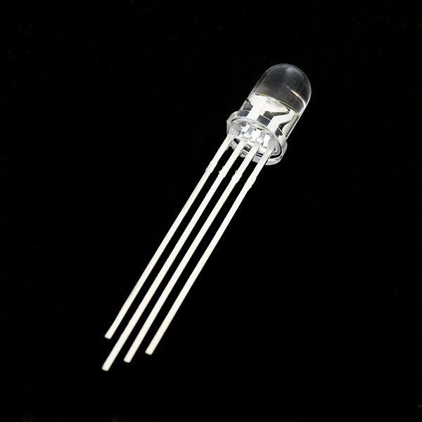
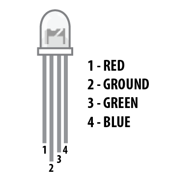
- RGB LED— Why use an LED that can only be one color when you can have any color?
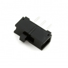
- SPDT (Single-Pole, Dual Throw) Switch— It’s a switch! You slide it back and forth, and it fits into a breadboard just great.
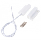
- Magnetic Door Switch— A mountable magnetic switch used in home automation and security. Great for detecting when a door or drawer is opened!
- BME280 Atmospheric Sensor Breakout— A sensor for detecting temperature, pressure and humidity. It communicates using the I2C serial communication protocol. The header pins are soldered on for you, which makes connecting this to your project nice and easy.
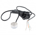
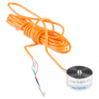
- Soil Moisture Sensor— The name describes it pretty well!
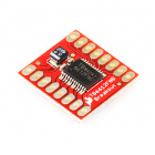
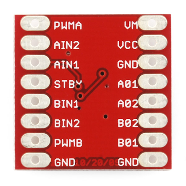
- SparkFun Motor Driver— This nifty little board is perfect for controlling the speed and direction of up to two separate motors.
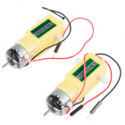
- Hobby Gearmotor Set— A set of hobby level motors (two of ‘em) with gearboxes set to 120 RPM.
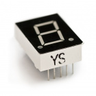
- 7 Segment Display— It’s an LED that lets you display numerals via the combination of lit-up segments, just like an alarm clock from the 1980s!
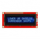
- 3.3V 16x2 White on Black LCD— This LCD can display 16 characters on two lines with a snazzy white-on-black background appearance. It operates at 3.3 volts (this is the voltage that the Tessel 2 is most comfortable with).
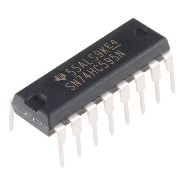
- 74HC595 Shift Register— An integrated circuit (IC) that allows you to increase the number of inputs and outputs you can control from a microcontroller.
Suggested Reading
While you can get through this guide without doing any outside reading, the following tutorials cover the essential core of electronics and circuits and are super useful:
What is a Circuit?
Every electrical project starts with a circuit. Don't know what a circuit is? We're here to help.
How to Use a Breadboard
Welcome to the wonderful world of breadboards. Here we will learn what a breadboard is and how to use one to build your very first circuit.
Analog vs. Digital
This tutorial covers the concept of analog and digital signals, as they relate to electronics.
Open Source!
At SparkFun, our engineers and educators are constantly improving kits such as these and coming up with new experiments. We would like to give attribution to Rick Waldron and Bocoup, as he originally started the development of Johnny-Five many years ago. The contents of this guide are licensed under the Creative Commons Attribution Share-Alike 4.0 Unported License.
To view a copy of this license visit this link, or write: Creative Commons, 171 Second Street, Suite 300, San Francisco, CA 94105, USA.
About the Tessel 2
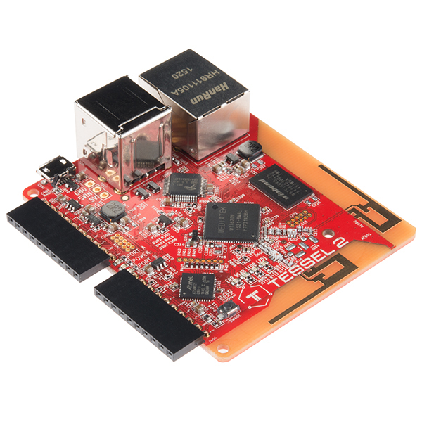
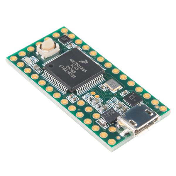
![!The Tessel 2 Development Board]()
The Tessel 2 is an open-source development board. It runs JavaScript and supports npm, which means scripts to control it can be built with Node.js. It’s a platform for experimenting, tinkering, prototyping and producing embedded hardware, perfect for the Internet of Things.
OK, So What’s a Development Board?
Development boards are platforms for prototyping and building embedded systems. At the heart of (most) development boards is a microcontroller, which combines a processor and memory with IO capabilities. Microcontrollers like the one on the Tessel 2 provide a collection of GPIO (general-purpose IO) pins for connecting input and output devices to. The pins on the microcontroller itself—a chip—are small, too small for human fingers to work with easily (plus you’d need to solder things to them). Development boards instead connect these GPIO pins to pin sockets that are easy to plug things into.
Other common features of boards play a supporting role: connections for programming and communicating with the board, status lights and reset buttons, power connections.
More powerful boards like the Tessel 2 and the well-known Raspberry Pi are sometimes also called single-board computers (SBCs).
Tessel 2’s Features
The Tessel is a mighty little board. Some of Tessel 2’s specifications include:
- 2 USB ports (you can connect cameras or flash storage, for example)
- 10/100 ethernet port
- 802.11 b/g/n WiFi
- 580MHz Mediatek router-on-a-chip (you can turn your Tessel 2 into an access point!)
- 48MHz SAMD21 coprocessor (for making IO zippy)
- 64MB DDR2 RAM, 32MB of flash (lots of space for your programs and stuff)
Working with Tessel 2
Tessel has a set of command-line interface (CLI) tools for setting up and working with the Tessel 2 board. You’ll install these and do a one-time set-up provisioning of your Tessel.
You can write scripts for the Tessel 2 in any text editor, using JavaScript and including npm modules as you desire. A one-line terminal command deploys and executes your script on the Tessel.
Inputs and Outputs
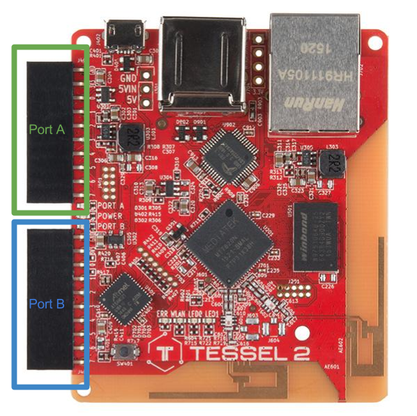
There are two primary sets of pins on the Tessel 2: Port “A” and Port “B”. Each port has 10 pins: two pins for power (3.3V and ground) and eight GPIO pins.
![The Tessel 2's GPIO pins: Port A and Port B]()
Some pins support different features. You can read details about every Tessel 2 pin, or just keep that info handy for reference later.
Powering the Board
There are multiple ways to power the Tessel 2. We’ll start by using the included USB cable.
Over USB
![alt text]()
Connecting to the board directly with USB will allow you to easily modify any circuits and re-deploy code from the comfort of your desk, without having to retrieve your project. This is also handy when you don’t have access to the local network (for deploying code over WiFi).
USB Wall Charger
![alt text]()
Once you have completely set up and provisioned your Tessel 2, you can deploy code through your local WiFi network. At some point you’ll itch to make your Tessel free of wires and tethering, but it still needs power. We supplied a 5V USB charger in the J5IK so you can place your project in a semi-remote location around your home or office and deploy code from anywhere on your local network.
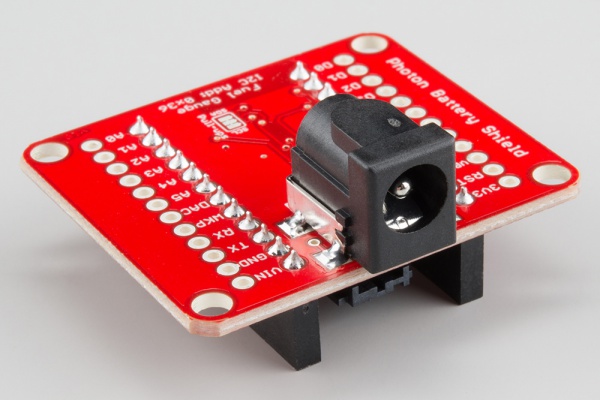
USB Battery Pack
![alt text]()
USB Battery packs are becoming quite popular as swag and giveaways at events. We collect them like candy because they allow us to power projects with minimal consideration to power management circuitry. If you have one of these handy, just use the included USB cable to plug the Tessel 2 into your battery and away you go! That’s it, simple as pie.
Ports and Pins on the Tessel 2
The Tessel 2 has two IO modules, Port A and Port B. Each port has 8 GPIO (general-purpose I/O) pins. Here’s their naming conventions and what all of them do.
![alt text]()
Pin Naming Conventions
The pins on the Tessel 2 are broken out across the two different ports. The naming conventions in code will be referenced with the port letter first and then the pin number of that port. The port letter is not case sensitive! As an example, the first pin on port A would be referred to as pin a0 or A0. Use this table as a reference in terms of the naming of pins.
| Port | Pin Number | Johnny-Five Name |
|---|
| A | 0 | “a0” or “A0” |
| A | 1 | “a1” or “A1” |
| A | 2 | “a2” or “A2” |
| A | 3 | “a3” or “A3” |
| A | 4 | “a4” or “A4” |
| A | 5 | “a5” or “A5” |
| A | 6 | “a6” or “A6” |
| A | 7 | “a7” or “A7” |
| B | 0 | “b0” or “B0” |
| B | 1 | “b1” or “B1” |
| B | 2 | “b2” or “B2” |
| B | 3 | “b3” or “B3” |
| B | 4 | “b4” or “B4” |
| B | 5 | “b5” or “B5” |
| B | 6 | “b6” or “B6” |
| B | 7 | “b7” or “B7” |
Pin Capabilities: What Each Pin Can Do
The pins of each port have different functionalities available to them.
Other things to know:
- All eight numbered pins, both ports (16 total), can be used as GPIO.
- Pins
4 and 7 on Port A support analog-to-digital input. All pins on Port B support analog input. - Pins
5 and 6 on both ports support Pulse-Width Modulation (PWM). - Pins
0 and 1 on both ports can be used for I2C serial communication. - Serial TX/RX (hardware UART) is available on both port, pins
5 (TX) and 6 (RX). - Port B, Pin
7: Supports digital-to-analog conversion (DAC)
The two ports are essentially duplicates, with the following exceptions:
- Port B: All numbered pins can be used for analog input.
- Port B, Pin
7: Supports DAC.
For exhaustive details, see the pin functionality reference chart below:
| Port | Pin Number | Digital I/O | SCL | SDA | TX | RX | Analog In | Analog Out | Interrupt | PWM |
|---|
| A | 0 | | | | | | | | | |
| A | 1 | | | | | | | | | |
| A | 2 | | | | | | | | | |
| A | 3 | | | | | | | | | |
| A | 4 | | | | | | | | | |
| A | 5 | | | | | | | | | |
| A | 6 | | | | | | | | | |
| A | 7 | | | | | | | | | |
| B | 0 | | | | | | | | | |
| B | 1 | | | | | | | | | |
| B | 2 | | | | | | | | | |
| B | 3 | | | | | | | | | |
| B | 4 | | | | | | | | | |
| B | 5 | | | | | | | | | |
| B | 6 | | | | | | | | | |
| B | 7 | | | | | | | | | |
Software Installation and Setup
Let’s prepare the software side of things so you’re ready to build stuff in this guide. You’ll need to have a few things installed, and you’ll want to set up a project area for your JavaScript programs. So, don’t skip ahead!
Installing Needed Things
You’re going to need:
- A text editor
- Node.js
- A terminal application
Installing a Text Editor: Atom
You will need a text editor in which to edit and save your JavaScript files. This means a plain text editor, not a Word document. If you’ve already got one, like SublimeText, Notepad++, vim, etc., groovy. If not, go ahead and install Atom.
![atom text editor logo]()
You can use any text editor you like if you already have on installed and are up and running. But, if you have never used a text editor to write JavaScript, HTML, etc. we recommend using Atom. Atom is a free and open source text editor that works on all three major operating systems, is light weight and when you get comfortable…it’s hackable!
Download Atom by heading to the Atom website.
![alt text]()
Installing Node.js
![node.js logo]()
Node.js is a JavaScript runtime, that is, it’s software that can execute your JavaScript code. Node.js has special features that support some of the best potentials of the JavaScript programming language, like event-driven, non-blocking I/O. npm is Node’s package manager. It’s a giant repository of encapsulated bits of reusable useful code, called modules, that you can use in your programs. npm will get installed for you when you install Node.js.
![alt text]()
Installing Node.js is a straightforward download-and-double-click process. Head on over to the Node.js website. Heads up: You’ll want to select the “LTS” version for download (LTS stands for long-term support). At time of writing, LTS is v4.4.5:
![alt text]()
Using a Terminal: Command Line Basics
Working with the Tessel is just like doing web development. But if you’re not familiar with web development, you might want to take a minute or two to get comfortable with some key tools of the trade: the command line (the “terminal”, where you execute commands) and the text editor, where you will work on and save your programs. Tessel’s site has a great resource to help you get started with terminal.
In the context of this tutorial, things that should be run in the command line look like this:
hello i am a command line command!
You’ll see this when you get to the first experiment. But, don’t skip ahead—you’ll need the tools we install in the next step.
Setting up a Project Working Area
Take a moment to set up a working area (directory) where you can put the programs for your Johnny-Five Inventor Kit (J5IK). You’ll also need to initialize the new project with npm and install needed npm modules for both Johnny-Five and Tessel.
You can accomplish all of this by typing (or copying and pasting) the following commands in a terminal:
mkdir j5ik;
cd j5ik;
npm init -y;
npm install johnny-five tessel-io;
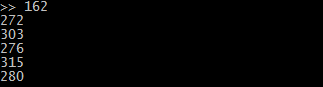
Running these commands will generate some output in your terminal. If everything goes smoothly, you’ll see some output about edits to a package.json file, and some additional output as npm installs the needed modules. You may also see a few WARN statements about missing description or repository field. Don’t worry—nothing’s broken.
An example of the kind of output you’ll see (though yours will differ in some particulars):
Wrote to /your/path/j5ik/package.json:
{"name": "j5ik","version": "1.0.0","description": "","main": "index.js","scripts": {"test": "echo \"Error: no test specified\"&& exit 1"
  },"keywords": [],"author": "","license": "ISC"
}

j5ik@1.0.0 /your/path/j5ik
├── johnny-five
└── tessel-io
npm WARN j5ik@1.0.0 No description
npm WARN j5ik@1.0.0 No repository field.
Hardware Installation and Setup
It’s time to get your Tessel 2 set up. The steps we’ll walk through now include:
- Installing the
t2-cli software tool - Connecting the Tessel 2 with a USB cable
- Finding, renaming and provisioning the Tessel
- Updating the Tessel’s firmware
Installing the Command-Line Tool
Note to Linux users:- If you are making a global installation on a Linux computer, be sure to add sudo in front of your npm installation command!
- Some Linux distrobutions require a few more library installs for `t2-cli` to work! Please install the libraries with the following command: apt-get install libusb-1.0-0-dev libudev-dev. You can find further documentation here.
You interact with the Tessel 2 using a command-line interface (CLI) tool called t2-cli. This tool can be installed using npm (Node.js' package manager, which gets installed automatically with Node.js).
Type the following into your terminal:
npm install t2-cli -g
The -g piece of that command (a flag) is important—this will tell npm to install the package globally, not just in the current project or directory.
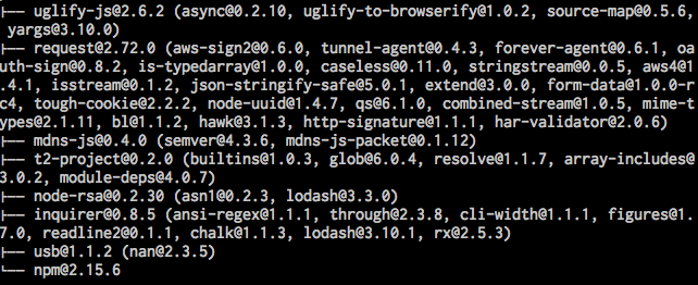
The installation will take a few moments, and you will see a bunch of stuff scroll by that looks sort of like this:
![alt text]()
Troubleshooting
Note: If you see any warnings or errors when trying to install t2-cli, the first thing to check is your Node.js version. To do this, type the following command in your terminal:
node –version
You’re aiming for the LTS (long-term support) version of Node.js, which at time of writing is v4.4.5. Learn more about how to upgrade and manage node versions with nvm.
Setting up your Tessel!
Now, time to get your hands dirty and get things up and running! Connect your Tessel 2 to your computer and give it about 30 seconds to boot up.
![alt text]()
Once your Tessel 2 has booted (the blue LED will be steady instead of blinking), type the following command into your terminal:
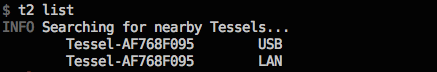
t2 list
The t2-cli tool will look for connected Tessels. Tessels can be connected by USB or over WiFi, but for now, it should spot your single, USB-connected Tessel. You’ll see something like this:
![alt text]()
Success! You can now communicate with your Tessel 2!
Naming Your Tessel 2
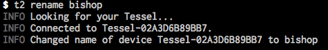
Giving your Tessel 2 a name is not required to use it, but it’s fun and friendly. To name your Tessel 2 use the following command:
t2 rename [name]
For example we renamed our Tessel 2 “Bishop” by typing following.
t2 rename bishop
The t2-cli tool will respond with the following output:
![alt text]()
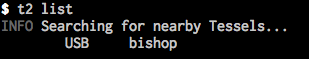
Double-check it!
t2 list
![alt text]()
Connecting Your Tessel 2 to the Internet
If you’ve ever configured and connected other embedded systems to the Internet, the simplicity of this should make you grin.
You’ll need to be connected to your local WiFi network first. To connect your Tessel to a WiFi network, type the following command into your terminal:
t2 wifi -n [SSID] -p [password]
Replace [SSID] with the name of your wireless network (careful! It’s case-sensitive) and [password], well, I be you can figure that out!
You’ll see some output that looks something like the following:
INFO Looking for your Tessel...
INFO Connected to bishop.
INFO Wifi Enabled.
INFO Wifi Connected. SSID: your-network-ssid, password: your-network-password, security: psk2
That’s it! Simple as pie!
You can do a bunch of other stuff with your Tessel and network connectivity. Tessel’s website has in-depth documentation on WiFi connection options.
Troubleshooting
Note: Like Kindles and some Androids, Tessel 2’s don’t play nice with 5GHz WiFi networks.
Provision Your Tessel 2
Your Tessel exists, has a name, and is connected to your WiFi network. The next step is to provision the Tessel. That creates a secure, trusted connection between your computer and the Tessel, whether it’s connected by wire or over the air (WiFi). You’ll need to do this before you can deploy code to the Tessel.
Type the following command in your terminal:
t2 provision
You’ll see something like:
INFO Looking for your Tessel...
INFO Connected to bishop.
INFO Creating public and private keys for Tessel authentication...
INFO SSH Keys written.
INFO Authenticating Tessel with public key...
INFO Tessel authenticated with public key.
Verify it worked:
t2 list
You’ll see your Tessel twice! That’s because it’s connected via USB and WiFi.
INFO Searching for nearby Tessels...
USB bishop
LAN bishop
Great! We have one last setup step.
Update Your Tessel 2
The Tessel community is constantly improving the software and firmware for the Tessel 2. It’s likely that in the time between your Tessel 2’s manufacture and now, the firmware has been updated. To update your Tessel, type the following command in your terminal:
t2 update
The update process can last some time, so I would recommend a snack break or checking up on some news feeds while this happens. When the update is finished you will get the command prompt back, and you are all ready to go with your Tessel 2!
Experiment 1: Blink an LED
Introduction
Making an LED (Light-Emitting Diode) blink is the most basic “Hello, World!” exercise for hardware, and is a great way to familiarize yourself with a new platform. In this experiment, you’ll learn how to build a basic LED circuit and use Johnny-Five with your Tessel 2 to make the LED blink and pulse. In doing so, you’ll learn about digital output and Pulse Width Modulation (PWM).
Perhaps you’ve controlled LEDs before by writing Arduino sketches (programs). Using Johnny-Five + Node.js to control hardware is a little different, and this article will illustrate some of those differences. If you’re totally new to all of this — not to worry! You don’t need any prior experience.
Parts Needed
You will need the following parts for this experiment:
- 1x Tessel 2 and USB cable
- 1x Breadboard
- 1x Standard LED (Choose any color in the bag full of LEDs)
- 1x 100Ω Resistor
- 2x Jumper Wires
Using a Tessel 2 without the kit? No worries! You can still have fun and follow along with this experiment. We suggest using the parts below:
In stock
PRT-12002
This is your tried and true white solderless breadboard. It has 2 power buses, 10 columns, and 30 rows - a total of 400 tie i…
24In stock
COM-12062
We all know that you can never get too many LEDs. Don't worry, we've got you covered. This is a pack of basic red, yellow, bl…
6In stock
PRT-12795
These are 6" long jumper wires with male connectors on both ends. Use these to jumper from any female header on any board, to…
1In stock
DEV-13841
The Tessel 2 is a development board with on-board WiFi capabilities that allows you to build scripts in Node.js. This Tessel …
In stock
COM-13761
These are 1/4th Watt, +/- 5% tolerance PTH resistors. Commonly used in breadboards and perf boards, these 100 Ohm resistors m…
Suggested Reading
The following tutorials provide in-depth background on some of the hardware concepts in this experiment:
Introducing LEDs
Diodes are electronic components that only allow current to flow through them in a single direction, like a one-way street. Light-Emitting Diodes (LEDs) are a kind of diode that emit light when current flows through them.
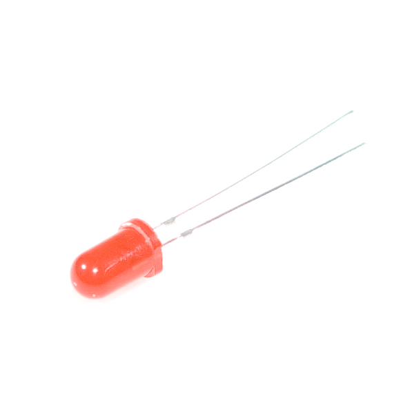
![Photo of a standard red LED]()
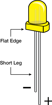
Grab an LED and take a look at it. The longer leg is called the anode. That’s where current enters the LED. The anode is the positive pin and should always be connected to current source. The shorter leg, the cathode, is where current exits the LED. The cathode is the negative pin and should always be connected to a pathway to ground. Many LEDs also have a flat spot on the cathode (negative) side.
![Drawing of LED parts: anode and cathode]()
If you apply too much current to an LED, it can burn out. We need to limit the amount of current that passes through the LED. To do that, we’ll use a resistor. When you use a resistor in this way to limit current, it is called — surprise! — a current-limiting resistor. With the Tessel 2 board, you should use a 100 Ohm resistor. We have included a baggy of them in the kit just for this reason!
If you’re curious to learn more about how voltage, current and resistance relate to one another, read this tutorial about Ohm’s Law.
Hardware Hookup
Its now the fun part! It’s time to start building your circuit. Let’s take a look at what goes into building this circuit.
Polarity
LEDs are polarized, meaning they need to be oriented in a specific direction when they are plugged in. You don’t want to plug a polarized part in backward!
On the other hand, resistors are not polarized; they’re symmetric, which means they don’t have an opinion about which way current flows across them. You can plug a resistor in facing either direction in a circuit, and it will be just fine.
Plugging Things In
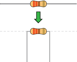
When working with components like resistors, you’ll need to bend their legs at (about) 90° in order to correctly fit into the breadboard sockets. You can trim the legs shorter to make them easier to work with, if you like:
![Bent resistor]()
All jumper wires work the same. They are used to connect two points together. All of the experiments in this guide will show the wires with different colored insulations for clarity, but using different combinations of colors is completely acceptable.
![Image of jumper wires]()
Breadboards are vital tools for prototyping circuits. Inside the breadboard there are electrical connections between certain sockets. Power rails— columns on the left and the right of the breadboard — are electrically connected vertically, while terminal rows— rows in the middle of the breadboard — are connected horizontally (note that connections do not continue across the center notch in the breadboard).
![image of breadboard]()
You can read a tutorial about breadboards to learn more.
Build the LED Circuit
Each of the experiments in this guide will have a wiring diagram. They’ll show you where to plug in components and how to connect them to your Tessel 2.
![alt text]()
Having a hard time seeing the circuit? Click on the wiring diagram for a closer look.
- Plug the LED into the breadboard, taking care to plug the cathode into row 1 and the anode into row 2. Make sure not to plug it in backward!
- Connect a 100Ω resistor between the LED’s cathode and ground as shown, spanning the notch in the middle of the breadboard.
- Use jumper wires to connect the breadboard’s components to the Tessel 2: connect ground (row 1) to the Tessel 2’s Port A GND pin and source (row 2) to the Tessel 2’s Port A, Pin 5.
Using Johnny-Five to Make an LED Blink
Open your favorite code editor, create a file called led.js and save it in the j5ik/ directory. Type — or copy and paste — the following JavaScript code into your led.js file:
language:javascript
var Tessel = require("tessel-io");
var five = require("johnny-five");

var board = new five.Board({
  io: new Tessel()
});

board.on("ready", () => {
  var led = new five.Led("a5");
  led.blink(500);
});
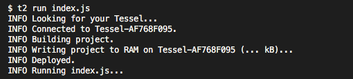
Now for the big reveal! Type — or copy and paste — the following into your terminal:
t2 run led.js
You terminal will display something like this:
![alt text]()
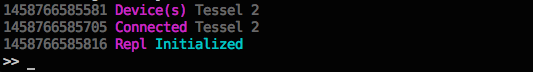
And when the program starts up:
![alt text]()
What You Should See
Your LED should be blinking:
Exploring the Code
Let’s take a deeper look at what’s going on in the led.js Johnny-Five code.
Requiring Modules
In Node.js, a program can use any number of code modules. Modules are independent chunks of functionality. The software functionality for Tessel and Johnny-Five is contained within modules. We need to tell Node.js to require those modules so that they are available to the program:
language:javascript
var Tessel = require("tessel-io");
var five = require("johnny-five");
Note: For Node.js to be able to find and use the modules, you need to use npm to install for the project. That happened when you set up your working environment—you used npm install to install both the tessel-io and johnny-five modules.
Instantiating Objects
Next, the code needs to instantiate (create) a new object that represents the Tessel 2 board, and assign it to a variable (board) so we can access it later:
language:javascript
var board = new five.Board({
  io: new Tessel()
});
This creates a new instance of a Johnny-Five Board.
Johnny-Five supports many kinds of development boards. The support for some boards is built right in to Johnny-Five, but others — including Tessels — rely on external plugins encapsulated in modules. That’s why the code requires the tessel-ionpm module. Here, we tell Johnny-Five to use a Tessel object for IO when communicating with the board.
Learn more: Working with JavaScript Objects
Listening for Events
JavaScript code statements are typically executed top to bottom, in order, until they’re “done” (the program runs to completion) and nothing is left to do. One of Node.js' great powers is to allow programmers to “schedule” things to happen outside of this simple sequential-then-done flow. A program will terminate if there’s nothing left to do, but there are a number of ways to give the program something to do so that it keeps running.
Because the Tessel 2 board initialization involves hardware and I/O, it takes a few moments—considerably longer than the rest of the led.js script would take to execute. The initialization of the board won’t get in our program’s way—it happens asynchronously, allowing our script to keep executing statements without blocking—but we need to schedule something to happen when the board is ultimately ready.
language:javascript
board.on("ready", function() {
  // ...this will execute when the board emits the `ready` event
});
The code snippet defines a function that will get executed when (‘on’) the board emits the ready event.
Next we need to fill in what that function should do when the board is ready to go.
Learn more: In-depth: JavaScript’s Concurrency Model and Event Loop
Blinking the LED
Once the board is ready, it’s time to configure an LED on Port A, Pin 5 and then tell that LED to blink. In Johnny-Five, that looks like this:
language:javascript
board.on("ready", function() {
  var led = new five.Led("a5");
  led.blink(500);
});
Instances of Johnny-Five’s Led class have some handy tools (attributes and methods) for doing LED things—for example, blink..
This code creates a new Led object and tells it what pin to use (in this case "a5"). Then it tells the LED to blink every 500 milliseconds (half a second). That means the LED will cycle 500ms off, then 500ms on.
Comparing Node.js + Johnny-Five With Arduino Sketches
The structure of Node.js scripts written with Johnny-Five differs from how Arduino sketches are written in the Arduino Programming Language. The following is an example sketch in the Arduino Programming Language that would make an LED blink on and off (assuming that LED was connected to pin 13 of a theoretical board):
language:cpp
void setup() {
  pinMode(13, OUTPUT); // Set up pin 13 as an OUTPUT pin
}

void loop() {
  digitalWrite(13, HIGH);   // turn the LED on (HIGH puts voltage on the pin)
  delay(500);               // wait for a half second
  digitalWrite(13, LOW);    // turn the LED off by making the voltage LOW
  delay(500);               // wait for a half second
}
Arduino sketches have two sections:
setup: runs once and is a place for configuring pins and initializing stuffloop: runs over and over and over and over
Another thing you’ll notice is that Arduino code is lower-level, meaning that there are fewer abstractions of specific hardware details. Instead of having an LED object that can do LED-like things (blink, pulse, fade, etc.), you interact directly with the digital pin and write LOW and HIGH states to it.
Between those digital writes, you tell everything to stop and wait for 500 milliseconds (delay). And the thing about delay is: it stops everything. It’s a process-blocking operation. Nothing else can happen while delay, well, delays.
In terms of code complexity, the difference between Johnny-Five and the Arduino Programming Language isn’t too significant when you’re just blinking an LED, but when it comes to pulsing an LED, Arduino sketch code starts getting more complicated.
Pulsing an LED
Now that we’ve covered the basics and some of the lower level technical aspects of Johnny-Five, let’s write a program that pulses the LED. Instead of blinking the LED on and off, pulsing fades the LED smoothly from off to on, and then from on to off again.
Pulse Width Modulation (PWM)
The state of a digital output pin can only be one of two things: LOW or HIGH. That means, at any given exact moment, an LED connected to the pin can only be off or on. We fool the eye into thinking an LED is dimmed to, say, half brightness by using a technique called Pulse Width Modulation (PWM)
With PWM, the pin can be switched between HIGH and LOW very quickly, causing the LED turn on and off, too. This cycle between on and off happens too fast for the human eye to discern. The percentage of time that the pin (with the LED attached) is HIGH (on) over a given period is its duty cycle. A 30 percent duty cycle (on — or HIGH — 30% of the time) will make an LED look like it’s partially lit — dimmer than bright but definitely on. By adjusting the duty cycle over time, we can fake (very convincingly!) an LED fading on and off.
Only certain pins on development boards support PWM. On the Tessel 2, pins 5 and 6 on both ports (A and B) support PWM.
Pulsing an LED With Arduino
Pulsing an LED in an Arduino sketch (Arduino Programming Language) requires more effort than blinking. Much has changed here from the blinking sketch, but certain things remain the same. There is still a process-blocking operation (delay), this time for 30ms on each loop cycle. We can no longer use the digitalWrite() function (it can only write binary LOW or HIGH); instead we’ll need the analogWrite() function for writing PWM values from 0 (0% duty cycle) to 255 (100% duty cycle). There are also now three variables to keep track of: led for the pin number, brightness to track the present brightness state, and lastly fadeAmount which holds the increase or decrease value to be applied to the value of brightness. Whew!
Here’s what that looks like all together:
language:cpp
int led = 9;           // the PWM pin the LED is attached to
int brightness = 0;    // how bright the LED is
int fadeAmount = 5;    // how many points to fade the LED by

void setup() {
  pinMode(led, OUTPUT);
}

void loop() {
  analogWrite(led, brightness);

  brightness = brightness + fadeAmount;

  if (brightness == 0 || brightness == 255) {
    fadeAmount = -fadeAmount ;
  }

  delay(30);
}
It may be hard to get your head around the logic in that program. It’s not that easy to read. It doesn’t scream “pulse an LED” in the way that it expresses itself, does it?
Pulsing an LED With Johnny-Five
Let’s see what pulsing an LED looks like in Johnny-Five. Open your led.js script again. You’ll need to edit one line. Change the line that currently reads:
led.blink(500);
to
led.pulse(500);
No kidding—that’s it! No need to keep track of things, handle scheduling and timing or do arithmetic—instances of Johnny-Five’s Led do it all for you. Like blink, the pulse method takes an argument that is the pulse period in milliseconds. Here is the complete script for your copying-and-pasting convenience:
language:javascript
var Tessel = require("tessel-io");
var five = require("johnny-five");

  var board = new five.Board({
    io: new Tessel()
  });

  board.on("ready", function() {
    var led = new five.Led("a5");
    led.pulse(500);
  });
Remember, to run the script and see your LED pulse, type — or copy and paste — the following command in a terminal:
t2 run led.js
What You Should See
Your LED should be pulsing in 500ms period cycles.
Building Further
Try adjusting the speed passed to the led.blink() and led.pulse() calls. For example: led.blink(1000) or led.pulse(1000) would change the cycles to 1000ms periods.
Reading Further
Experiment 2: Multiple LEDs
Introduction
In Experiment 1 of the Johnny-Five Inventor’s Kit (J5IK), you learned how to blink and pulse a single LED with a Tessel 2. In this experiment, you’ll learn how to control multiple, colorful LEDs with Johnny-Five to create animated variations on a simple “Cylon effect.” This article dives into structuring looping logic for your projects using Johnny-Five and JavaScript fundamentals.
Suggested Reading
The following tutorials provide in-depth background on some of the hardware concepts in this experiment:
- What is a Circuit?– This tutorial will explain what a circuit is, as well as discuss voltage in further detail.
- Voltage, Current, Resistance, and Ohm’s Law– Learn the basics of electronics with these fundamental concepts.
- LEDs (Light-Emitting Diodes)– LEDs are found everywhere. Learn more about LEDs and why they are used in so many products all over the world.
- Resistors– Why use resistors? Learn more about resistors and why they are important in circuits like this one.
- Polarity– Polarity is a very important characteristic to pay attention to when building circuits.
Parts Needed
You will need the following parts for this experiment:
- 1x Tessel 2
- 1x Breadboard
- 6x LEDs (One of each color: red, orange, yellow, green, blue, purple)
- 6x 100Ω Resistor
- 7x Jumper Wires
Using a Tessel 2 without the kit? No worries! You can still have fun and follow along with this experiment. We suggest using the parts below:
In stock
PRT-12002
This is your tried and true white solderless breadboard. It has 2 power buses, 10 columns, and 30 rows - a total of 400 tie i…
24In stock
COM-12062
We all know that you can never get too many LEDs. Don't worry, we've got you covered. This is a pack of basic red, yellow, bl…
6In stock
PRT-12795
These are 6" long jumper wires with male connectors on both ends. Use these to jumper from any female header on any board, to…
1In stock
DEV-13841
The Tessel 2 is a development board with on-board WiFi capabilities that allows you to build scripts in Node.js. This Tessel …
In stock
COM-13761
These are 1/4th Watt, +/- 5% tolerance PTH resistors. Commonly used in breadboards and perf boards, these 100 Ohm resistors m…
Hardware Hookup
Its now the fun part! It’s time to start building your circuit. Let’s take a look at what goes into building this circuit.
| Polarized Components | Pay special attention to the component’s markings indicating how to place it on the breadboard. Polarized components can only be connected to a circuit in one direction. |
Build the Multiple-LED Circuit
![alt text]()
Having a hard time seeing the circuit? Click on the wiring diagram for a closer look.
- Connect the LEDs to the breadboard. Make sure to connect their cathode legs to sockets in the ground column in the power rail.
- Plug in the 100Ω resistors in terminal rows shared with the anode legs of the LEDs, spanning the central notch.
- Connect jumper wires between the resistors and the Tessel 2. You may find it helpful to use colors that correspond to the LED’s color.
- Use a jumper wire to connect the ground power rail of the breadboard to the Tessel 2’s GND pin.
Lighting Up LEDs Side-to-Side
Open your favorite code editor, create a file called side-to-side.js and save it in the j5ik/ directory. Type — or copy and paste — the following JavaScript code into your side-to-side.js file:
language:javascript
var five = require("johnny-five");
var Tessel = require("tessel-io");
var board = new five.Board({
  io: new Tessel()
});
board.on("ready", () => {
  var leds = new five.Leds(["a2", "a3", "a4", "a5", "a6", "a7"]);
  var index = 0;
  var step = 1;

  board.loop(100, () => {
    leds.off();
    leds[index].on();
    index += step;
    if (index === 0 || index === leds.length - 1) {
      step *= -1;
    }
  });
});
Before you run this on your Tessel 2, pause for a moment. Can you tell what the program will do?
Type – or copy and paste – the following command into your terminal and press enter:
t2 run side-to-side.js
Once the program starts up, your multiple-LED circuit should light up in a pattern like this:
Exploring the Code
Before continuing, we recommend that you’ve read Experiment 1: Exploring the Code.
The side-to-side program lights up LEDs in the following pattern:
- From lowest pin number to highest pin number, turn on one LED at a time every 100 milliseconds, then:
- From highest pin number to lowest pin number, turn on one LED at a time every 100 milliseconds, then:
- Repeat from step 1.
Collections of LEDs With the Leds Class
Instead of instantiating each LED as its own object separately using the Led class (as we did in Experiment 1), we can create a single collection that contains all of the LEDs in one swoop:
language:javascript
board.on("ready", function() {
  var leds = new five.Leds(["a2", "a3", "a4", "a5", "a6", "a7"]);
});
Johnny-Five’s Leds constructor takes an Array of pin numbers and creates an Led object for each of them. Each of these Led objects can be accessed and manipulated from the container-like leds object. Instances of the Leds class behave like Arrays but have some extra goodies (they’re described as “Array-like objects”).
Read up on JavaScript Arrays if the concept is new or you’re feeling rusty.
Looping in Johnny-Five
To turn on LEDs one at a time, we need some way of creating a loop that executes every 100 milliseconds. We’re in luck. Board object instances have a loop method that can do just that! Convenient!
language:javascript
board.on("ready", () => {
  board.loop(100, () => {
    // ... This function gets invoked every 100 milliseconds
  });
});
The function (in this case, an arrow function]) passed as the second argument to loop will get invoked every 100 milliseconds. Now, let’s see what needs to happen in that loop.
Lighting Up, Lighting Down
Here’s what we need to accomplish in each invocation of the loop callback function:
language:javascript
board.on("ready", () => {
  var index = 0;
  var step = 1;

  board.loop(100, () => {
    leds.off();            // 1. Turn all of the LEDs off
    leds[index].on();      // 2. Turn on the "next" active LED
    // ...                 // 3. Determine what the next active LED will be
  });
});
In step one, all LEDs are turned off. Leds instances have an off method that will turn off every Led in its collection. Easy peasy.
The variable index holds the index of the next LED that should get turned on. The initial value of index is 0. Why 0? Each Led in leds can be accessed by its numeric index, like an Array:
| Reference | LED |
|---|
leds[0] | Led object controlling red LED on Port A, Pin 2 |
leds[1] | Led object controlling red LED on Port A, Pin 3 |
leds[2] | Led object controlling red LED on Port A, Pin 4 |
leds[3] | Led object controlling red LED on Port A, Pin 5 |
leds[4] | Led object controlling red LED on Port A, Pin 6 |
leds[5] | Led object controlling red LED on Port A, Pin 7 |
The first time the loop executes, index is 0, and it will turn on leds[0], which is the first (red) LED on Port A, Pin 2:
language:javascript
leds[index].on();
Step 3 sets us up for the next time the loop function executes. The value of index needs to be set to the index of the next LED that should turn on. This is what the step variable helps us with. Add step to index to get the index of the next LED to light up:
language:javascript
board.on("ready", () => {
  var index = 0;
  var step = 1;

  board.loop(100, () => {
    leds.off();            // 1. Turn all of the LEDs off
    leds[index].on();      // 2. Turn on the "next" active LED
    index += step;         // 3a. Add `step` to index
  });
});
At the completion of the first invocation of the loop callback function, index will hold the value 1.
During the second invocation, the second, orange LED (leds[1]) will light up. index will be incremented to 2.
And so on, lighting up red, orange, yellow, green, blue … But then we get to the purple LED (Port A, Pin 7) at index 5. There is no Led element at leds[6], so what do we do now? Well, we can flip the sign of step, changing its value to -1:
language:javascript
board.on("ready", () => {
  var index = 0;
  var step = 1;

  board.loop(100, () => {
    leds.off();            // 1. Turn all of the LEDs off
    leds[index].on();      // 2. Turn on the "next" active LED
    index += step;         // 3a. Add `step` to index
    if (index === leds.length - 1) { // 3b. If we're at the highest index...
      step *= -1; // ...invert the sign of step
    }
  });
});
Now invocations of the loop callback function will decrease (decrement) the index value, and the LEDs will light up in reverse order. When the index gets down to 0— the first LED — we need to swap the sign of step again:
language:javascript
board.on("ready", () => {
  var index = 0;
  var step = 1;

  board.loop(100, () => {
    leds.off();            // 1. Turn all of the LEDs off
    leds[index].on();      // 2. Turn on the "next" active LED
    index += step;         // 3a. Add `step` to index
    // If we are at the lowest OR the highest index...
    if (index === 0 || index === leds.length - 1) {
      step *= -1;
    }
  });
});
Using board.loop with the leds can be adapted in various ways to change the way the LEDs light up. Let’s try a few variations.
Variation: One-by-One On, One-by-One Off
Now we’ll light up each LED one at a time and keep them on as we go; the display will loop as:
- From lowest pin number to highest pin number, turn on each LED and keep it on.
- From highest pin number to lowest pin number, turn off each LED and keep it off.
- Repeat from step 1.
Open your favorite code editor, create a file called one-by-one-on-off.js and save it in the j5ik/ directory. Type — or copy and paste — the following JavaScript code into your one-by-one-on-off.js file:
language:javascript
var five = require("johnny-five");
var Tessel = require("tessel-io");
var board = new five.Board({
  io: new Tessel()
});
board.on("ready", () => {
  var leds = new five.Leds(["a2", "a3", "a4", "a5", "a6", "a7"]);
  var index = 0;
  var step = 1;

  board.loop(100, () => {
    leds.off().slice(0, index).on();
    index += step;
    if (index === 0 || index === leds.length) {
      step *= -1;
    }
  });
});
All of the changes are confined to the loop callback function. There’s one line doing much of the heavy lifting here:
leds.off().slice(0, index).on();
This single line turns all of the LEDs off and then turns on all LEDs between 0 and the current index. slice is an Array method that returns a chunk of an array between the start and end indexes provided (leds isn’t an Array, remember, but it acts like one, so it also has a slice method).
As in the previous example, this script will flip the sign on step when it reaches either end of the leds collection.
Run the script by typing – or copying and pasting – the following command in your terminal:
t2 run one-by-one-on-off.js
Once the program starts up, your LEDs circuit should display something like this:
Variation: One-by-One On, Clear and Repeat
Now let’s simplify that same program: light up each pin, one at a time, and then turn them off; the display will loop as:
- From lowest pin number to highest pin number, turn on each LED and keep it on.
- Once all the LEDs are on, turn them all off
- Repeat from step 1.
Open your favorite code editor, create a file called one-by-one-clear-repeat.js and save it in the j5ik/ directory. Type – or copy and paste – the following JavaScript code into your one-by-one-clear-repeat.js file:
language:javascript
var five = require("johnny-five");
var Tessel = require("tessel-io");
var board = new five.Board({
  io: new Tessel()
});
board.on("ready", () => {
  var leds = new five.Leds(["a2", "a3", "a4", "a5", "a6", "a7"]);
  var index = 0;

  board.loop(100, () => {
    if (index === leds.length) {
      leds.off();
      index = 0;
    } else {
      leds[index].on();
      index++;
    }
  });
});
Again, there is very little to change here, so we’ll skip right to the operations within the call to board.loop(...).
language:javascript
board.loop(100, () => {
  if (index === leds.length) {
    leds.off();
    index = 0;
  } else {
    leds[index].on();
    index++;
  }
});
The semantics for this program are slightly different from the previous examples. Because we’re always lighting LEDs up in the same direction — lowest to highest index — we don’t have to deal with the logic for swapping the sign on a step variable. Instead, a simple increment of the index value on each invocation of the loop callback function is all we need, resetting it to 0 when we run out of LED indexes.
- If the
index equals the number of LEDs in the leds collection, - Turn all
ledsoff. - Set the
index back to 0. - Else,
- Turn the
led at present indexon. - Increment the
index.
Type — or copy and paste — the following into your terminal:
t2 run one-by-one-clear-repeat.js
Once the program starts up, your LEDs circuit should display something like this:
Variation: Collision
Changing gears a bit, this next program will light LEDs from the middle, out, and back (there will be two LEDs lit at a time); the display will loop as:
- From the first to the last and the last to the first, by pin number, light the LEDs one at a time.
- Repeat from step 1.
Open your favorite code editor, create a file called collision.js and save it in the j5ik/ directory. Type — or copy and paste — the following JavaScript code into your collision.js file:
language:javascript
var five = require("johnny-five");
var Tessel = require("tessel-io");
var board = new five.Board({
  io: new Tessel()
});
board.on("ready", () => {
  var leds = new five.Leds(["a2", "a3", "a4", "a5", "a6", "a7"]);
  var index = 0;
  var step = 1;

  board.loop(100, () => {
    leds.off();
    leds[index].on();
    leds[leds.length - index - 1].on();

    index += step;

    if (index === 0 || index === leds.length - 1) {
      step *= -1;
    }
  });
});
This example contains logic more in line with the first few variations again — turning on the correct LED and then determining what the next LED’s index will be:
- Turn all
ledsoff. - Turn the
leds at index and its counterpart on. - Update the
index with step (either 1 or -1). - If
index equals 0, or index equals the number that corresponds to the last possible led in the leds collection, flip the sign of step.
Type — or copy and paste — the following into your terminal:
t2 run collision.js
Once the program starts up, your LEDs circuit should display something like this:
Building Further
- Try writing your own algorithms for other patterns not shown here.
Reading Further
- JavaScript– JavaScript is the programming language that you’ll be using:
- Node.js– Node.js is the JavaScript runtime where your programs will be executed.
- Johnny-Five– Johnny-Five is a framework written in JavaScript for programming hardware interaction on devices that run Node.js.
Experiment 3: Reading a Potentiometer
Introduction
So far the experiments have been focused on output: writing code with Johnny-Five to control the state of one or more LEDs. In this experiment, you’ll learn how to read analog input data from a potentiometer. You’ll learn about how development boards (like the Tessel 2) sample and process analog input and how to use data from analog sources to make things happen. Using data from the potentiometer, you’ll control a bar graph in your terminal, alter the brightness of an LED and control the activity of multiple LEDs.
Suggested Reading
The following tutorials provide in-depth background on some of the hardware concepts in this experiment:
Parts Needed
You will need the following parts for this experiment:
- 1x Tessel 2
- 1x Breadboard
- 1x Potentiometer
- 1x Standard LED (any color)
- 1x 100Ω Resistor
- 7x Jumper Wires
Using a Tessel 2 without the kit? No worries! You can still have fun and follow along with this experiment. We suggest using the parts below:
In stock
PRT-12002
This is your tried and true white solderless breadboard. It has 2 power buses, 10 columns, and 30 rows - a total of 400 tie i…
24In stock
COM-12062
We all know that you can never get too many LEDs. Don't worry, we've got you covered. This is a pack of basic red, yellow, bl…
6In stock
COM-09806
There are lots of trimpots out there. Some are very large, some so small they require a screwdriver. Here at SparkFun, we jus…
6In stock
PRT-12795
These are 6" long jumper wires with male connectors on both ends. Use these to jumper from any female header on any board, to…
1In stock
DEV-13841
The Tessel 2 is a development board with on-board WiFi capabilities that allows you to build scripts in Node.js. This Tessel …
In stock
COM-13761
These are 1/4th Watt, +/- 5% tolerance PTH resistors. Commonly used in breadboards and perf boards, these 100 Ohm resistors m…
Introducing Potentiometers
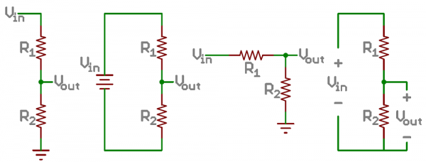
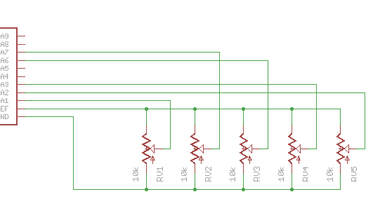
A potentiometer is a resistance-based analog sensor that changes its internal resistance based on the rotation of its knob. The potentiometer has an internal voltage divider, creating a varying voltage on the center pin. The voltage on the center pin changes as the knob is turned. You can use an analog input pin to read this changing voltage.
![alt text]()
Hardware Hookup
Its now the fun part! It’s time to start building your circuit. Let’s take a look at what goes into building this circuit.
| Polarized Components | Pay special attention to the component’s markings indicating how to place it on the breadboard. Polarized components can only be connected to a circuit in one direction. |
Build the Potentiometer Circuit
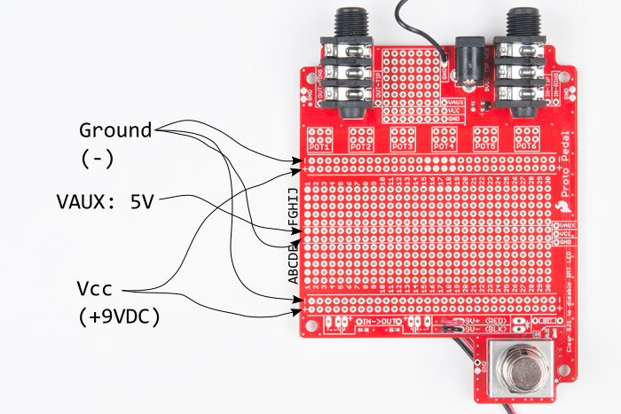
To hook up the potentiometer, attach the two outside pins to a supply voltage (3.3V in this circuit) and ground. It doesn’t matter which is connected where, as long as one is connected to power, and the other to ground. The center pin is then connected to an analog input pin so the Tessel 2 can measure changes in voltage as the knob is turned.
Note: The potentiometer included in the kit has three marks on it that will help you figure out which breadboard rows the pins are plugged into.
![alt text]()
Having a hard time seeing the circuit? Click on the wiring diagram for a closer look.
- Connect the potentiometer to the breadboard. Connect the potentiometer’s power pins (supply and ground) to the power rail with jumper wires and connect the middle pin to the Tessel 2’s Port A, Pin 7.
- Connect the LED. Use a jumper wire to connect the Tessel 2’s Port B, Pin 5 through the 100Ω resistor and to the LED’s anode (positive, longer) leg. Connect the LED’s cathode to ground on the power rail. Double-check the legs on the LED to make sure you haven’t plugged it in backward!
- Use jumper wires to connect the Tessel 2’s 3.3V and GND pins to the breadboard’s power rails.
Reading Analog Sensors With Johnny-Five
Open your favorite code editor, create a file called sensor-basic.js and save it in the j5ik/ directory. Type — or copy and paste — the following JavaScript code into your sensor-basic.js file:
language:javascript
var five = require("johnny-five");
var Tessel = require("tessel-io");
var board = new five.Board({
  io: new Tessel(),
  repl: false,
  debug: false,
});

board.on("ready", () => {
  var sensor = new five.Sensor("a7");

  sensor.on("change", () => console.log(sensor.value));
});
Note: For programs that output a lot of data quickly to the terminal such as this one, we recommend deploying your code over LAN for best results.
To Deploy Code Over WiFi:- Connect your Tessel to the same Wifi network as your computer t2 wifi -n[SSID] -p[PASSWORD]`
- Make sure that your Tessel is provisioned and shows up in your list of Tessels using t2 list. See the Hardware Installation and Setup for how to provision your Tessel if it doesn't show up in your list.
- Deploy your code using the
--lan tag. Example:t2 run mycode.js --lan
Type — or copy and paste — the following into your terminal:
t2 run sensor-basic.js
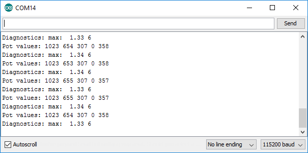
This isn’t particularly interesting, as all it does is output the value of the sensor (integers between 0 and 1023) until the program is interrupted. yawn
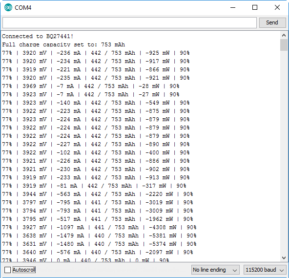
![alt text]()
You should see something similar to this. Your sensor values (0-1023) being logged in the console.
Exploring the Hardware
Analog Input
For software to be able to work with data coming from an analog sensor, it first needs to be converted from an analog signal (infinite possible values) to a digital signal (discrete set of values). The microcontroller on the Tessel 2 does this analog-to-digital conversion (ADC) for you, sampling the incoming analog voltages and converting them to a range of values between 0 (0V) and 1023 (3.3V). Values in between are quantized to the nearest integer.
Asynchronous I/O
In Experiment 1: Blink an LED, we looked at the asynchronous nature of Node.js runtime, comparing how the Arduino Programming Language’s delay function is blocking, while Johnny-Five’s execution model follows the Node.js convention: non-blocking. Listening for Boardready events is an example of a common asynchronous pattern. Non-blocking I/O is extremely important to the JavaScript-for-hardware story, and the Tessel 2 has an exemplary implementation.
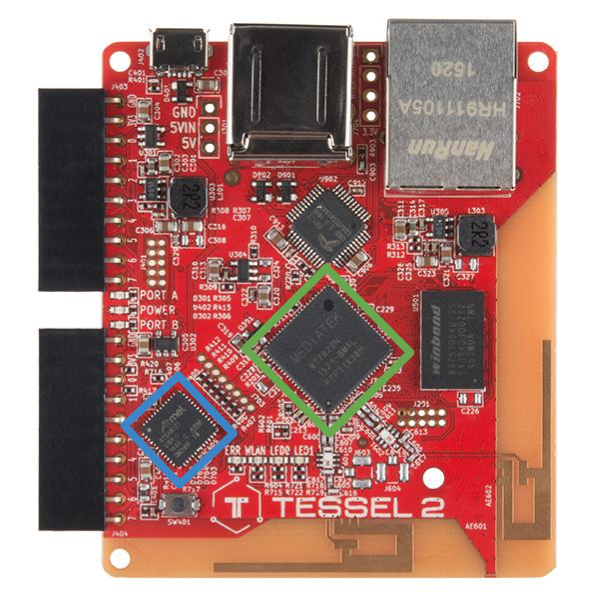
Tessel 2’s support for asynchronous, non-blocking I/O is in its hardware. In addition to the Mediatek chip (that’s where your code executes), it has a second processor (Atmel® SAMD21) that is responsible for I/O.
The MediaTek processor and the Atmel coprocessor exchange messages representing I/O state. Code that executes on the MediaTek chip (the Linux user space) has asynchronous access to the state captured on SAMD21. For example, if a digital input pin goes HIGH, the SAMD21 sends a message to the MediaTek chip and any code running can elect to consume that message. When code running on the MediaTek chip wants to output values to the SAMD21 to be written to an output pin, it simply sends the message, then keeps going.
![alt text]()
The MediaTek chip (green) and the Atmel SAMD21 (blue) allow for Asynchronous I/O on your Tessel 2.
For the purpose of our experiment, it’s helpful to understand that when program code running on the MediaTek chip wants to know the value of an analog input, it sends a request for that information, registers a handler (a function) and continues on. Sometime “later” (likely within a millisecond or two), and always in a different execution turn, the SAMD21 responds with the present value of the input. The registered handler is then invoked with response value. This may happen once or repeatedly, but never causes the program to stop and wait.
Exploring the Code
Notice that the Board constructor call is being passed an object with two properties that we haven’t seen before: repl: false and debug: false. These settings tell Johnny-Five to shut off both the “on-by-default” REPL (Read–Eval–Print Loop, an interactive prompt) and connection debugging output.
Once the board has emitted the ready event, hardware inputs are ready for interaction:
language:javascript
var sensor = new five.Sensor("a7");
The first thing to do is create an instance of the Sensor class, indicating that this sensor is attached to Port A, Pin 7.
language:javascript
sensor.on("change", () => console.log(sensor.value));
Then, a handler function is registered for change events, meaning that anytime the reading changes, the function will be called.
Every time this function is called and the sensor value is displayed, it occurs in a different execution turn than the previous invocation, staying true to the asynchronous, non-blocking model. The handler function for change events simply logs sensor.value. sensor.value is a 10-bit number (0-1023), representing the last successful ADC-processed read from the Sensor object’s associated analog input pin.
Note: The minimum version of Node.js that runs on Tessel 2 supports many ES2015 features, including Arrow Functions, so we’re using those here to simplify the program.
Variation: Sensor Input Graphing
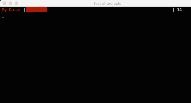
For this experiment, you will be “bar chart graphing” light intensity values in your terminal using the Barcli module:
![barcli]()
barcli [bahrk-lee]
Barcli is a simple tool for displaying real-time data in the console. Multiple instances of Barcli can be stacked to show multiple axes, sensors or other data sources in an easy-to-read horizontal bar graph.
In your terminal, make sure you’re inside the working directory (j5ik), then type — or copy and paste — the following command:
npm install barcli
We’ll make our sensor data a little more interesting (than just numbers scrolling by). Let’s visualize it as a graph displayed directly in the terminal. Open your favorite code editor, create a file called sensor-graph.js and save it in the j5ik/ directory.
Type — or copy and paste — the following JavaScript code into your sensor-graph.js file:
language:javascript
var Barcli = require("barcli");
var five = require("johnny-five");
var Tessel = require("tessel-io");
var board = new five.Board({
  io: new Tessel()
});

board.on("ready", function() {
  var range = [0, 100];
  var graph = new Barcli({
    label: "My Data",
    range: range,
  });
  var sensor = new five.Sensor({
    pin: "a7",
    threshold: 5 // See notes below for detailed explanation
  });

  sensor.on("change", () => {
    graph.update(sensor.scaleTo(range));
  });
});
Note: For programs that output a lot of data quickly to the terminal such as this one, we recommend deploying your code over LAN for best results.
To Deploy Code Over Wifi:- connect your Tessel to the same Wifi network as your computer t2 wifi -n[SSID] -p[PASSWORD]`
- Make sure that your Tessel is provisioned and shows up in your list of Tessels using t2 list, see Hardware Installation and Setup for how to provision your Tessel if it doesn't show up in your list.
- Deploy your code using the
--lan tag. Example:t2 run mycode.js --lan
Type — or copy and paste — the following into your terminal:
t2 run sensor-graph.js
Once the program starts up, the terminal should display something like this:
![alt text]()
Exploring the Code
We’ve now required the Barcli module:
language:javascript
var Barcli = require("barcli");
… which means it can be put to use in your program.
To create a graph, we’ll need an instance of a Barcli object. First, though, we need to define a range of values that are valid for the graph:
language:javascript
var range = [0, 100];
var graph = new Barcli({
  label: "My Data",
  range: range,
});
The graph object is now able to represent values from 0 to 100. However, recall that values coming from the potentiometer will range from 0 to 1023. We’ve got to scale those, too, so that they can be graphed!
The way we’re instantiating the Sensor object looks a bit different from the previous example. Instead of passing the constructor a String identifying the pin, like so:
language:javascript
var sensor = new five.Sensor("a7");
… we’re using the options object form here, which allows us to pass a whole object full of extra information to the constructor:
language:javascript
var sensor = new five.Sensor({
  pin: "a7",
  threshold: 5
});
Let’s talk about that threshold property. It defines how much a sensor’s value needs to change before a change event is emitted. The default value of threshold is 1. As you saw in the first example, any change to the sensor’s value – remember, values range from 0 to 1023 and are whole numbers (integers) – will cause a change event. For this variation, that’s too much sensitivity.
Specifically, we want to define a threshold that will limit the change events to those that are relevant to our range, which is 0-100. Since we’ll be scaling the sensor’s value from 0-1023 to 0-100, we only care about changes of approximately every 10 steps in 1023 (obviously that’s fudging a little, and you’re encouraged to be more precise in your actual programs). The threshold value is exactly half of the approximate step:
> (value + 5)< (value - 5)
Finally, the program replaces the call to console.log(...) with a call to graph.update(...) and passes the result of calling the sensor object’s scaleTo(...) method with the same range as graph is using:
language:javascript
sensor.on("change", () => {
  graph.update(sensor.scaleTo(range));
});
Unpacking the line:
language:javascript
graph.update(sensor.scaleTo(range));
When invocations are nested like this, they proceed from the inside out. First, the sensor object’s 10-bit value is scaled to 0-100 (range) and then that resulting value is passed to the graph object’s update method.
Variation: Using Sensor Input to Create Output
For the final variation of this experiment, you’ll process the sensor readings to control the brightness of the LED in your circuit. Open your favorite code editor, create a file called sensor-input-to-output.js and save it in the j5ik/ directory. Type — or copy and paste — the following JavaScript code into your sensor-input-to-output.js file:
language:javascript
var five = require("johnny-five");
var Tessel = require("tessel-io");
var board = new five.Board({
  io: new Tessel()
});

board.on("ready", function() {
  var sensor = new five.Sensor({
    pin: "a7",
    threshold: 2
  });
  var led = new five.Led("b5");

  sensor.on("change", () => {
    led.brightness(sensor.scaleTo(0, 255));
  });
});
Type — or copy and paste — the following into your terminal:
t2 run sensor-input-to-output.js
Once the program starts up, LED should display something like this:
Exploring the Code
Again, we’re instantiating a Sensor object to represent the potentiometer, and defining a threshold. This time we’ll set it to 2, because the rounded result of 1023 (the top of the 10-bit sensor range) divided by 255 (the top of the 8-bit brightness range) is 4, and threshold should be set to half of the full step size:
language:javascript
var sensor = new five.Sensor({
  pin: "a7",
  threshold: 2
});
Next, a new instance of the Led class is created, with Pin 5 on Port B:
language:javascript
var led = new five.Led("b5");
+The change event remains the same, but the operation within the handler is updated to call the led object’s brightness(...) method, passing the sensor’s value scaled from its 10-bit input range (0-1023) to the 8-bit output range (0-255) of the led:
 language:javascript
 sensor.on("change", () => {
   led.brightness(sensor.scaleTo(0, 255));
 });
Alternatively, the conversion could have been written as a bit-shifting operation, where the 10-bit value is shifted 2 bits to the right, since brightness(...) expects an 8-bit value (0-255). This bit-shifting operation is the most efficient way to scale the 10-bit analog input value to the 8-bit PWM output value:
language:javascript
0b1111111111 === 1023;
0b0011111111 === 255;
0b11111111 === 255;
(0b1111111111 >> 2) === 255;
And could be applied in our code like so:
language:javascript
sensor.on("change", () => {
  led.brightness(sensor.value >> 2);
});
This snippet means “shift the sensor.value 2 bits to the right” — the two right-most bits are discarded. Voila! An 8-bit number from a 10-bit number.
Building Further
- Experiment with bit shifting in your Node.js console.
Reading Further
- JavaScript– JavaScript is the programming language that you’ll be using:
- Node.js– Node.js is the JavaScript runtime where your programs will be executed.
- Johnny-Five– Johnny-Five is a framework written in JavaScript for programming hardware interaction on devices that run Node.js.
Introduction
In Experiment 3, you journeyed into the fun world of input by reading data from an analog sensor. This experiment continues that journey, moving now into digital input. You’ll learn how digital input differs from analog input, and you’ll meet a useful new component: the push button (also sometimes called a momentary switch). You’ll learn how to control a single LED with button presses, and then how to control multiple LEDs from multiple buttons.
Suggested Reading
The following tutorials provide in-depth background on some of the hardware concepts in this experiment:
Parts Needed
To complete this experiment, you’ll build two circuits. You’ll need the following parts:
- 1x Tessel 2
- 1x Breadboard
- 2x Standard LED (any color is fine)
- 2x Push Button
- 2x 100Ω Resistors
- 2x 10kΩ Resistors
- 12x Jumper Wires
Using a Tessel 2 without the kit? No worries! You can still have fun and follow along with this experiment. We suggest using the parts below:
In stock
PRT-12002
This is your tried and true white solderless breadboard. It has 2 power buses, 10 columns, and 30 rows - a total of 400 tie i…
24In stock
COM-12062
We all know that you can never get too many LEDs. Don't worry, we've got you covered. This is a pack of basic red, yellow, bl…
6In stock
COM-09190
This is a standard 12mm square momentary button. What we really like is the large button head and good tactile feel (it 'clic…
4In stock
PRT-12795
These are 6" long jumper wires with male connectors on both ends. Use these to jumper from any female header on any board, to…
1In stock
DEV-13841
The Tessel 2 is a development board with on-board WiFi capabilities that allows you to build scripts in Node.js. This Tessel …
In stock
COM-11508
1/6th Watt, +/- 5% tolerance PTH resistors. Commonly used in breadboards and perf boards, these 10K resistors make excellent …
In stock
COM-13761
These are 1/4th Watt, +/- 5% tolerance PTH resistors. Commonly used in breadboards and perf boards, these 100 Ohm resistors m…
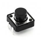
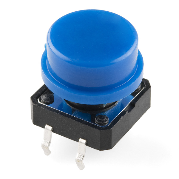
Introducing the Push Button
![alt text]()
A momentary push button is a kind of switch, closing (completing) a circuit while it is being actively pressed. If you take a push button and look at it, you’ll notice it has four pins, which might seem like a lot of pins. Let’s walk through how the pins are connected to each other.
The four pins on a push button are split into two pairs. Each pin is adjacent to two other pins: the other half of its pair (on the opposite side of the button) and a pin not paired with it (located on the same side). A pin is always electrically connected to the other pin in its pair, but is only connected to the other adjacent pin when the button is actively being pressed. When you press down on the button and get a nice “click,” the button bridges the two sets of pins and allows current to flow through the circuit.
How do you know which pins are paired up? The buttons included in this kit will only fit across the breadboard ditch in one direction. Once you get the button pressed firmly into the breadboard (across the ditch), the pins are horizontally paired. The pins toward the top of the breadboard are connected, and the pins toward the button of the breadboard are connected.
Note: Not all buttons share this pin format. Please refer to the data sheet of your specific button to determine which pins are paired up.
All right, now we have a sense of how a button can complete a circuit, but we need the right kind of circuit for our button. Button presses need to cause a digital input on the Tessel to move between HIGH and LOW logic levels when the button is pressed. The circuits in the two wiring diagrams for this experiment use a 10kΩ pull-down resistor with the buttons to make sure that the Tessel will read the button circuit as LOW (off/false) when the button isn’t pressed and HIGH (on/true) when it is.
Hardware Hookup
Your kit comes with four different colored push buttons. All push buttons behave the same, so go ahead and use your favorite color!
| Polarized Components | Pay special attention to the component’s markings indicating how to place it on the breadboard. Polarized components can only be connected to a circuit in one direction. |
Build the Button Circuit
![alt text]()
Having a hard time seeing the circuit? Click on the wiring diagram for a closer look.
- Connect the pushbutton to the breadboard. It should only fit in one orientation spanning the center notch. Use jumper wires to connect one of the right-hand pins of the button to the ground power rail, through a 10kΩ resistor, as shown. Connect the other pin of the right side of the button to the supply power rail with another jumper wire.
- Starting from a socket on the same row as the 10kΩ resistor — but on the opposite side of it from the button — connect a jumper wire to the Tessel’s Port A, Pin 0.
- Plug the LED into the breadboard as shown, making sure the anode (longer leg) is closer to the top of the breadboard. Connect the cathode (shorter leg) to the ground power rail using a jumper wire. Connect the anode, through a 100Ω resistor, to the Tessel 2’s Port A, Pin 5.
- Connect the Tessel’s +3.3V and GND pins to the breadboard’s power rails, using jumper wires.
Observing a Button With Johnny-Five’s Button Class
Open your favorite code editor, create a file called button.js and save it in the j5ik/ directory. Type — or copy and paste — the following JavaScript code into your button.js file:
language:javascript
var Tessel = require("tessel-io");
var five = require("johnny-five");

var board = new five.Board({
  io: new Tessel()
});

board.on("ready", () => {
  var button = new five.Button("a2");
  button.on("press", () => console.log("Button Pressed!"));
  button.on("release", () => console.log("Button Released!"));
});
Type — or copy and paste — the following into your terminal:
t2 run button.js
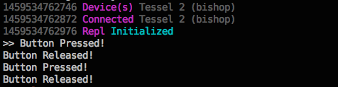
What You Should See
When you press the button, your terminal will display the appropriate message:
![alt text]()
Console output triggered by button events
Exploring the Code
Using Input to Control Output With Johnny-Five
OK, let’s make this do something a little more interesting before we dive in and look at how it works. Go back to your button.js and either type the changes or copy and paste the following code:
language:javascript
var Tessel = require("tessel-io");
var five = require("johnny-five");

var board = new five.Board({
  io: new Tessel()
});

board.on("ready", function() {
  var led = new five.Led("a5");
  var button = new five.Button("a2");
  button.on("press", () => led.on());
  button.on("release", () => led.off());
});
Type — or copy and paste — the following into your terminal:
t2 run button.js –single
The --single flag tells the T2 CLI to only deploy the single, specified file. This will preserve all other existing code on the Tessel 2 while still deploying your new program changes, which can make the deployment faster.
What You Should See
When you press the button, the LED should light up. When you release the button, the LED should turn off.
Exploring the Code
Once the board has emitted the ready event, we can initialize Led and Button instances to interact with our hardware on the specified pins:
language:javascript
var led = new five.Led("a5");
var button = new five.Button("a2");
The Johnny-Five Button class takes care of processing values from input in order to emit intuitive events for each state of the hardware. We’ve registered handlers for these events: press, hold and release.
When the button is pressed, turn the LED on:
language:javascript
button.on("press", () => led.on());
When the button is released, turn the LED off:
language:javascript
button.on("release", () => led.off());
Note: The minimum version of Node.js that runs on Tessel 2 supports many ES2015 features, including Arrow Functions, so we’re using those here to simplify the program.
Variation: Using Complex Input to Control Output With Johnny-Five
Go back to your button.js and either type the changes or copy and paste the following code:
language:javascript
var Tessel = require("tessel-io");
var five = require("johnny-five");

var board = new five.Board({
  io: new Tessel()
});

board.on("ready", function() {
  var led = new five.Led("a5");
  var button = new five.Button("a2");
  button.on("press", () => led.on());
  button.on("hold", () => led.blink(500));
  button.on("release", () => led.stop().off());
});
What You Should See
When the button is pressed, the LED turns on. If the button is held (longer than half a second), the button will start blinking. When the button is released, the LED will turn off.
Exploring the Code
This variation adds a handler for the Button object instance’s hold event.
When the button is held (defaults to 500ms hold time), change the output to blink in 500ms cycles:
language:javascript
button.on("hold", () => led.blink(500));
We need to make a small change to the release handler as well. When the button is released, we also need to stop any scheduled and running tasks (blink) before we turn the LED off:
language:javascript
button.on("release", () => led.stop().off());
Part II: Using Multiple Inputs to Control Multiple Outputs With Johnny-Five
Introduction
In Experiment 2, you saw how Johnny-Five’s Leds class could be used to manage a collection of Led objects. Similarly, the Buttons class can be used to control multiple Button instances. Buttons and Leds are both “Collections” classes. Instances of these Collections classes are Array-like objects that take care of instantiating the individual objects (Button, Led, e.g.) in their collection on your behalf.
The Collections class constructors are flexible. They’ll accept an Array that may contain pin numbers, configuration objects or existing instances of the component class they are initializing. Take a look at the following:
language:javascript
var a0 = new five.Led("a0");
var a1 = { pin: "a1", id: "some-custom-id" };
var a2 = "a2";
var leds = new five.Leds([a0, a1, a2]);
This would create an instance of the Leds class containing three Led instances, which each represent a single LED connected to a Tessel 2. These Collections classes do the busywork so you don’t have to.
The next few examples will use Collections classes to manage multiple inputs and outputs.
Hardware Hookup
The second circuit in this experiment builds on the first. Go ahead and add the additional components to match the wiring diagram:
![alt text]()
Having a hard time seeing the circuit? Click on the wiring diagram for a closer look.
Multiple Inputs and Outputs With Buttons
Open your favorite code editor, create a file called buttons-leds.js and save it in the j5ik/ directory. Type — or copy and paste — the following JavaScript code into your buttons-leds.js file:
language:javascript
var Tessel = require("tessel-io");
var five = require("johnny-five");

var board = new five.Board({
  io: new Tessel()
});

board.on("ready", function() {
  var leds = new five.Leds(["b5", "b6"]);
  var buttons = new five.Buttons(["a5", "a6"]);

  buttons.on("press", (button) => {
    leds.off();
    leds[buttons.indexOf(button)].on();
  });
});
Type — or copy and paste — the following command into your terminal:
t2 run buttons-leds.js –single
The --single flag tells the T2 CLI to only deploy the single, specified file. This will preserve the existing code on the Tessel 2 while still deploying your new program changes, which can make the deployment faster.
What You Should See
Pressing the first button should cause the first LED to light up. Pressing the second button should cause the second button to light up. Either LED will stay lit until the other button is pressed.
Exploring the Code
As always, once the board object has emitted the ready event, we can initialize instances of the Leds and Buttons Collections classes to interact with our hardware:
language:javascript
var leds = new five.Leds(["b5", "b6"]);
var buttons = new five.Buttons(["a5", "a6"]);
Here’s another cool thing about these Collections classes: instead of registering handlers on events for each of the objects in the collection’s list individually (tedious and bug-prone), you can listen to them all with a single handler:
language:javascript
buttons.on("press", () => {
  // Yay! One of the buttons was pressed
});
OK, but which button?:
language:javascript
buttons.on("press", button => {
  // The first argument (`button`) passed to the callback handler function
  // is a reference to the `Button` instance that was pressed
  // So...turn on the corresponding LED somehow...
});
We’ve mentioned this before — Collections classes act like Arrays, so much so that they are referred to as “array-like” (seriously! That’s a technical term nowadays). Some of the ways they act like Arrays: they have a length property, and you can access their constituent objects using numeric indices. We saw this in Experiment 2.
That means that the first Button object can be accessed as buttons[0] and the second as buttons[1]. Ditto for leds[0] and leds[1] for the Led objects.
| Collection Element | Object |
|---|
leds[0] | Led object instance (Port B, Pin 5) |
leds[1] | Led object instance (Port B, Pin 6) |
buttons[0] | Led object instance (Port A, Pin 5) |
buttons[1] | Led object instance (Port A, Pin 6) |
Now we could explicitly turn on a specific LED, accessing it by index:
language:javascript
buttons.on("press", button => {
  leds[0].on();
});
But we want to dynamically determine which LED to turn on. If the first button is pressed (buttons[0]), we should turn on the first LED (leds[0]). That means we need to know the index (0 or 1) of the button that is being pressed so we can turn on the corresponding LED.
Well, good news. Buttons is array-like enough that we can use the indexOf method like so:
language:javascript
buttons.on("press", button => {
  // Use indexOf method, just like a real Array
  // This will return the numeric index for the `button` object in `buttons`
  // (either 0 or 1)
  var index = buttons.indexOf(button);
  leds.off();  // Turn 'em all off first
  leds[index].on(); // Turn on the correct LED
});
Or more succinctly:
buttons.on("press", (button) => {
  leds.off();
  leds[buttons.indexOf(button)].on();
});
Building Further
- Create a game where an LED is lit after some random amount of time, and the player must turn it off before x amount of time has passed. The amount x may get shorter as the player progresses.
Reading Further
- JavaScript– JavaScript is the programming language that you’ll be using:
- Node.js– Node.js is the JavaScript runtime where your programs will be executed.
- Johnny-Five– Johnny-Five is a framework written in JavaScript for programming hardware interaction on devices that run Node.js.
Experiment 5: Reading an SPDT Switch
Introduction
You got your first taste of processing digital input in Exercise 4 by working with a push button. This experiment introduces a Single-Pole, Double-Throw (SPDT) switch. You’ll see how the Johnny-Five Switch class can be used with a variety of physical switches, including a magnetic switch that you can use to protect your lunch from marauding fridge raiders. This experiment also includes the integration of a third-party module and service, Twilio, which you can use to send SMS text messages — now that’s leveling up!
Suggested Reading
The following tutorial provides in-depth background on some of the hardware concepts in this experiment:
- Switch Basics— Types of switches, what they do, and how they work
Parts Needed
You will need the following parts for this experiment:
- 1x Tessel 2
- 1x Breadboard
- 1x Standard LED (any color is fine)
- 1x SPDT Switch
- 1x Magnetic Door Switch
- 1x 100Ω Resistor
- 7x Jumper Wires
Using a Tessel 2 without the kit? No worries! You can still have fun and follow along with this experiment. We suggest using the parts below:
In stock
PRT-12002
This is your tried and true white solderless breadboard. It has 2 power buses, 10 columns, and 30 rows - a total of 400 tie i…
24In stock
COM-12062
We all know that you can never get too many LEDs. Don't worry, we've got you covered. This is a pack of basic red, yellow, bl…
6In stock
PRT-12795
These are 6" long jumper wires with male connectors on both ends. Use these to jumper from any female header on any board, to…
1In stock
COM-00102
Simple SPDT slide switch. Rated at 30V/200mA. The pins have .1" spacing - fits great into a breadboard! Use it as a power swi…
In stock
COM-13247
This is the Magnetic Door Switch Set, a small reed switch assembly specifically designed to alert you when doors, drawers, or…
In stock
DEV-13841
The Tessel 2 is a development board with on-board WiFi capabilities that allows you to build scripts in Node.js. This Tessel …
In stock
COM-13761
These are 1/4th Watt, +/- 5% tolerance PTH resistors. Commonly used in breadboards and perf boards, these 100 Ohm resistors m…
Introducing the Single-Pole, Double-Throw (SPDT) Switch
![alt text]()
SPDTs have three legs: one common leg and two legs that vie for connection to the common leg. The common pin is in the middle. It’s always connected to one of the outside pins, but which pin it’s connected to depends on which way the switch is flipped. The state of the switch — “on” or “off” — is read from the common leg. A connected digital input pin on the Tessel will read HIGH when the common leg is electrically connected to the +3.3V leg on the switch; that means the switch is “on.” It will read LOW when the common pin is connected to the ground pin (switch in the “off” position).
Note: The circuit in this experiment doesn’t need a pull-down or pull-up resistor like the one in Experiment 4. That’s because the common pin in the switch is always connected to something. There’s never a “disconnected” state that can cause floating. There’s a nice tutorial about pull resistors if you’d like to learn more.
Hardware Hookup
This experiment has two wiring diagrams, but let’s not get ahead of ourselves! The first is below:
| Polarized Components | Pay special attention to the component’s markings indicating how to place it on the breadboard. Polarized components can only be connected to a circuit in one direction. |
Building the Switch Circuit
![alt text]()
Having a hard time seeing the circuit? Click on the wiring diagram for a closer look.
- Plug the LED in, be sure to note that the anode is towards the top of the breadboard with each leg plugged into its own row.
- Place the 100Ohm resistor so that one leg is in the same row of hole as the anode of the LED and spans the ditch plugging into the row adjacent to the LED.
- Using jumper wires connect the cathode of the LED to the ground rail of the breadboard and the a separate wire connecting the end of the resistor to Pin 5 of Port B on your Tessel.
- Insert the SPDT switch into the breadboard so that each of the 3 pins insert into their own rows.
- Using jumper wires connect the upper pin of the switch to the positive power rail, the lowest pin to the ground power rail and the center pin to Pin 5 on Port A of your Tessel.
6.Finally power the breadboard using jumper wires! connect 3.3V to the positive rail and GND to the ground rail.
Observing a Switch With Johnny-Five
Open your favorite code editor, create a file called switch.js and save it in the j5ik/ directory. Type — or copy and paste — the following JavaScript code into your switch.js file:
language:javascript
var Tessel = require("tessel-io");
var five = require("johnny-five");

var board = new five.Board({
  io: new Tessel()
});

board.on("ready", () => {
  var spdt = new five.Switch("a5");
  spdt.on("close", () => console.log("Switch closed"));
  spdt.on("open", () => console.log("Switch opened"));
});
Type — or copy and paste — the following into your terminal:
t2 run switch.js
Note: The minimum version of Node.js that runs on Tessel 2 supports many ES2015 features, including Arrow Functions, which we will be using throughout this experiment to simplify your program code.
What You Should See
When you slide the switch back and forth, your terminal will display the appropriate message:
![alt text]()
Exploring the Code
As in all previous experiments, once the board object has emitted the ready event, we can initialize an instance of the Switch class to interact with our hardware:
language:javascript
var spdt = new five.Switch("a5");
Next, create two event listeners: one for the close event (which means the switch is “on”) and one for the open event (the switch is “off”). These events are conceptually very similar to the Button events that we covered in Experiment 4. Buttons are, after all, a kind of switch too.
language:javascript
spdt.on("close", () => console.log("Switch closed"));
spdt.on("open", () => console.log("Switch opened"));
And that’s it! Flipping the switch back and forth will cause Switch closed and Switch opened messages to display in the console (your terminal window’s output).
Variation: Using a Switch to Control an LED with Johnny-Five
As a minor modification, create a new Led object and control its on/off state with the Switch. Type — or copy and paste — the following JavaScript code into your switch.js file:
language:javascript
var Tessel = require("tessel-io");
var five = require("johnny-five");

var board = new five.Board({
  io: new Tessel()
});

board.on("ready", function() {
  var led = new five.Led("b5");
  var spdt = new five.Switch("a5");
  spdt.on("close", () => led.on());
  spdt.on("open", () => led.off());
});
Type — or copy and paste — the following into your terminal:
t2 run switch.js
What You Should See
When the switch is in one position, the LED is off. When the switch is in its other position, the LED is on.
Exploring the Code
Just as we did in all previous experiments, once the board object has emitted the ready event, we can initialize instances of the Led and Switch classes to interact with our hardware:
language:javascript
var led = new five.Led("b5");
var spdt = new five.Switch("a5");
This time, instead of logging (displaying) messages, the Switch event handlers will turn the LED on or off, depending on which state the circuit is in:
language:javascript
spdt.on("close", () => led.on());
spdt.on("open", () => led.off());
Monitoring a Fridge With Johnny-Five
Ever had a pesky coworker who has a habit of swiping your lunch? Let’s try to catch her in the act! For this experiment, you’re going to make a surveillance device that will send us an SMS text message when a refrigerator door is opened.
Introducing the Magnetic Door Switch
In Experiment 4 and the first example in this experiment, you built circuits containing switches controlled by direct human contact: fingers pressing or flipping. The door switch included in the Johnny-Five Inventor’s Kit is a little different: it is sensitive to a magnetic field.
The switch assembly has two pieces. When the two halves of the switch assembly are very near each other, or touching, the switch is in one state. Moving the two halves more than 20mm apart from each other will cause the switch to change state. One half contains a magnet, and the other contains a reed switch, a switch that changes state when exposed to a magnetic field.
This type of two-piece switch is often used in home-security systems. One half of the switch is attached to a fixed surface, and the other half to a moving door or window. When the door or window is opened, the two halves are separated from each other, breaking the contact and changing the switch’s state.
Building the Circuit
Build the magnetic switch circuit using the wiring diagram:
![alt text]()
Having a hard time seeing the circuit? Click on the wiring diagram for a closer look.
- Using jumper wires, connect one half of the switch assembly to Port A, Pin 2 and the ground column of the breadboard’s power rail. It doesn’t matter which pin of the switch is connected to GND or the input pin — both orientations work fine.
- Plug in the LED. Connect the anode to Port A, Pin 5 through a 100Ω resistor. Connect the cathode to the ground column of the power rail using a jumper wire.
- Connect the Tessel’s GND pin to the breadboard’s power rail using a jumper wire.
Building a Prototype
Before we start sending SMS messages out into the ether, let’s use the circuit above to create a prototype. This will prove our hardware is set up correctly. For the moment, instead of dispatching a text message, we’ll indicate the switch’s status with an LED. We’ll turn the LED on when the “door opens” (switch halves are separated) and shut it off when the “door closes” (switch halves are near or touching).
Open your favorite code editor, create a file called intruder-alert.js and save it in the j5ik/ directory. Type — or copy and paste — the following JavaScript code into your intruder-alert.js file:
language:javascript
var Tessel = require("tessel-io");
var five = require("johnny-five");
var board = new five.Board({
  io: new Tessel()
});

board.on("ready", () => {
  var led = new five.Led("a5");
  var door = new five.Switch({
    pin: "a2",
    invert: true,
  });

  door.on("open", () => led.on());
  door.on("close", () => led.off());
});
Type — or copy and paste — the following command into your terminal:
t2 run intruder-alert.js
What You Should See
Opening and closing the magnet switch will turn the LED on and off, respectively.
Exploring the Code
There’s a small difference in how the Switch object is instantiated in this code example, compared with the SPDT example:
language:javascript
var door = new five.Switch({
  pin: "a2",
  invert: true,
});
In this case, we’re telling Johnny-Five to invert the switch, logically.
Consider the default state of the circuit in the SPDT example above and the pushbutton examples in Experiment 4. In those, when the switches are in their “off” position (or the button is not pressed), the associated digital input pin will read LOW.
Now, scroll back up and look at the wiring diagram image again for the magnetic door switch circuit. It would seem that when the two halves of the switch assembly are apart as shown, the circuit would be open and the digital pin would read LOW, like the earlier switch and button examples.
However, the internal wiring of this particular magnetic door switch works in such a way that the pin will read HIGH. When a switch or component has this kind of architecture, we say that it is pulled high—the circuit’s default, inactive state is HIGH rather than LOW.
The invert option tells Johnny-Five to invert its interpretation of the Switch’s states, such that HIGH reads correspond to the open event and LOW reads to the closed event. That way, pulling the two halves of the switch apart results in “open” and putting them together again is “closed,” which feels correct.
Note: Unless you pass a particular value for the type property, a Switch object instance will default to invert: true, so the behavior remains the same if you remove the invert:true from the code here.
Integrating SMS (Twilio) to the Surveillance Device
In order to enable SMS (text messaging), you’ll need to set up a trial account with Twilio:
Go to https://www.twilio.com/try-twilio and sign up for an account
Get your API credentials. Navigate to your account’s “dashboard”. Write down (or otherwise keep handy) both the Account SID and your Auth Token— you’ll need those for the program.
![alt text]()
Set up a Twilio phone number. Start by heading to the Phone Numbers dashboard page.
Click the Get Started button
![alt text]()
- Click the “Get your first Twilio phone number” button and walk through the steps.
![alt text]()
- Write down the number; you’ll need this for the program too.
![alt text]()
Twilio maintains an npm module that you can use. Install the Twilio module for Node.js by typing — or copying and pasting — the following command into your terminal:
npm install twilio
Type — or copy and paste — the following JavaScript code into your intruder-alert.js file:
language:javascript
var twilio = require("twilio");
var Tessel = require("tessel-io");
var five = require("johnny-five");
var board = new five.Board({
  io: new Tessel()
});

var accountSid = ""; // SID copied from www.twilio.com/console
var authToken = ""; // token copied from www.twilio.com/console

var sender = ""; // This is your Twilio phone number
var recipient = ""; // This is your own mobile phone number

var client = new twilio.RestClient(accountSid, authToken);

board.on("ready", () => {
  var door = new five.Switch({
    pin: "a2",
    invert: true,
  });

  door.on("open", () => {
    var details = {
      body: `Security Breach at ${Date.now()}`,
      from: sender,
      to: recipient,
    };

    client.messages.create(details, error => {
      if (error) {
        console.error(error.message);
      }
      // Success! Nothing else to do
    });
  });
});
Type — or copy and paste — the following into your terminal:
t2 run intruder-alert.js
When you remove the magnet, you should momentarily receive a text message warning you of an intruder!
Exploring the Code
The script instantiates a Twilio client object with the defined credentials. That object takes care of communicating back and forth with Twilio.
language:javascript
var accountSid = ""; // SID copied from www.twilio.com/console
var authToken = ""; // token copied from www.twilio.com/console

var sender = ""; // This is your Twilio phone number
var recipient = ""; // This is your own mobile phone number

var client = new twilio.RestClient(accountSid, authToken);
After the board is ready, a Switch is instantiated, just like before. But there is a change to the open event handler. When the door is opened:
door.on("open", () => {
  // 1. Define the details of the SMS to send
  // 2. Use the Twilio client to send the message
});
Fleshing that out:
language:javascript
door.on("open", () => {

  // SMS details
  var details = {
    body: `Security Breach at ${Date.now()}`,
    from: sender, // Twilio phone number
    to: recipient,  // You! (phone number)
  };

  // Send the SMS
  client.messages.create(details, error => {
    if (error) {
      console.error(error.message);
    }
    // Success! Nothing else to do
  });
});
The details object sets up a body for the text message (using a template literal and the JavaScript Date object), as well as sender and recipient phone numbers.
Then we rely on the Twilio client object for dispatching the message, invoking client.messages.create with the details object and also a callback function. If there is an error (the first argument to the callback function if so), log it to the console. Otherwise, we’re good—the message was sent successfully.
Building Further
- Turn a time lapse camera on and off – use a switch to turn on a time lapse camera app using tessel-av.
- Set an alarm – use a switch to turn an alarm clock app on and off
Reading Further
- JavaScript— the programming language that you’ll be using:
- Node.js— JavaScript runtime where your programs will be executed
- Johnny-Five— framework written in JavaScript for programming hardware interaction on devices that run Node.js.
Experiment 6: Reading a Light Sensor
All experiments will require a connection to the internet for installing JavaScript module packages via `npm`. This connection is not required for deploying the programs to your Tessel 2, but is at least required as a one-time setup operation.
Introduction
This isn’t your first rodeo with an analog sensor—this experiment will build on what you learned in Experiment 3: Reading a Potentiometer.
In this experiment, you’ll meet a new component: photoresistors. Also called photocells or Light-Dependent Resistors (LDRs), these simple sensors change resistance depending on ambient light intensity. You’ll learn why you need to use an additional resistor in your circuit to be able to read values from the photoresistor. You’ll build a bar graph to display changing light conditions. Then you’ll make a light-sensitive nightlight.
Throughout this experiment, you’ll use Johnny-Five’s Light class to read data from the photoresistor, and, in multiple examples, you’ll see how changing the scale of the data read from the photoresistor can be useful in further manipulating or presenting that data.
Suggested Reading
The following tutorials provide in-depth background on some of the hardware concepts in this experiment:
Parts Needed
You will need the following parts for this experiment:
- 1x Tessel 2
- 1x Breadboard
- 1x Photoresistor
- 1x Standard LED (any color is fine)
- 1x 10kΩ Resistor
- 1x 100Ω Resistor
- 6x Jumper Wires
Using a Tessel 2 without the kit? No worries! You can still have fun and follow along with this experiment. We suggest using the parts below:
In stock
PRT-12002
This is your tried and true white solderless breadboard. It has 2 power buses, 10 columns, and 30 rows - a total of 400 tie i…
24In stock
COM-12062
We all know that you can never get too many LEDs. Don't worry, we've got you covered. This is a pack of basic red, yellow, bl…
6In stock
SEN-09088
This is a very small light sensor. A photocell changes (also called a [photodetector](http://en.wikipedia.org/wiki/Photodetec…
6In stock
PRT-12795
These are 6" long jumper wires with male connectors on both ends. Use these to jumper from any female header on any board, to…
1In stock
DEV-13841
The Tessel 2 is a development board with on-board WiFi capabilities that allows you to build scripts in Node.js. This Tessel …
In stock
COM-13761
These are 1/4th Watt, +/- 5% tolerance PTH resistors. Commonly used in breadboards and perf boards, these 100 Ohm resistors m…
Introducing the Photoresistor
![photoresistor]()
The resistance of a photoresistor changes depending on how much light is hitting it. When it’s really bright, the photocell has less resistance—it’s more conductive. When it’s dim, the photocell has more resistance.
The resistance changes, yes, but the Tessel 2 analog input pins respond to changing voltage. Fortunately, there’s a straightforward way to create a circuit that translates changes in resistance to changes in voltage: use a voltage divider.
A voltage divider is a circuit that uses a pair of resistors to translate an input voltage (Vin) into different (always lower) voltage (Vout). All of the voltage that goes into the circuit has to get “used up” by the components in between the two resistors; all of the supply voltage (3.3V in our case) must be accounted for. If R1 and R2 in a voltage-divider circuit have equal resistance (say, two 100Ω resistors), the voltage at Vout will be one-half of the input voltage, or 1.15V—each gobbles up half of the voltage.
Each resistor drops its share of the supply voltage, proportional to its share of the circuit’s total resistance. If R1 is 300Ω and R2 is 100Ω, Vout is one-quarter (25%) of the input voltage because three-quarters has already been snatched up by R1. See? The second resistor didn’t change; it has a static resistance. Meanwhile, the changing resistance of R1 is translated into voltage changes at Vout.
In this example’s circuit, the second resistor will be a 10kΩ resistor. It won’t change resistance. It’ll just chill. But the photoresistor—that’ll change resistance as light changes, changing its proportional resistance in the context of the whole circuit. So, voila!, voltage at Vout changes, too, and we can read that using the Tessel.
![several ways of representing a voltage divider circuit]()
Several different schematic representations of a voltage divider
The photoresistor changes its resistance based on the light to which it is exposed. To use this with the Tessel 2 board, you will need to build a voltage divider with a 10kΩ resistor as shown in the wiring diagram for this experiment. The Tessel 2 board cannot read a change in resistance, only a change in voltage. A voltage divider allows you to translate a change in resistance to a corresponding voltage value.
The voltage divider enables the use of resistance-based sensors like the photoresistor in a voltage-based system. As you explore different sensors, you will find more resistance-based sensors that only have two pins like the photoresistor. To use them with your Tessel 2 board you will need to build a voltage divider like the one in this experiment. To learn more about resistors in general, check out our tutorial on resistors and also our tutorial on voltage dividers.
Note: Make sure you are using the 10kΩ resistor in your voltage divider with the sensors in this kit. Otherwise you will get odd and inconsistent results.
Hardware Hookup
Enough reading … let’s get this circuit built!
| Polarized Components | Pay special attention to the component’s markings indicating how to place it on the breadboard. Polarized components can only be connected to a circuit in one direction. |
Build the Photoresistor Circuit
![alt text]()
Having a hard time seeing the circuit? Click on the wiring diagram for a closer look.
- Plug the photoresistor into the breadboard. It works fine in either orientation (it is not polarized). Connect a 10kΩ resistor between one leg of the photoresistor and ground. On the other side of the resistor, but in the same row, connect the photoresistor to Tessel 2’s Port A, Pin 7 with a jumper wire.
- Connect the photoresistor to the supply voltage column on the power rail using a jumper wire. Connect the other end of the resistor to the ground column on the power rail with a jumper wire.
- Plug in the LED. Make sure not to plug it in backward! The anode (longer leg) should be connected with a jumper wire to Port B, Pin 6 through a 100Ω resistor. Connect the LED’s cathode to the ground column on the power rail with a jumper wire.
- Use jumper wires to connect the Tessel’s 3.3V and GND pins to the power rail of the breadboard.
Observing Light Intensity With Johnny-Five
Before we get into bar charts, let’s take a look at the most basic observation example. Open your favorite code editor, create a file called light.js and save it in the j5ik/ directory. Type—or copy and paste—the following JavaScript code into your light.js file:
language:javascript
var five = require("johnny-five");
var Tessel = require("tessel-io");
var board = new five.Board({
  io: new Tessel()
});

board.on("ready", () => {
  var light = new five.Light("a7");

  light.on("change", () => console.log(light.level));
});
Note: For programs that output a lot of data quickly to the terminal such as this one, we recommend deploying your code over LAN for best results.
To Deploy Code Over WiFi:- Connect your Tessel to the same Wifi network as your computer t2 wifi -n[SSID] -p[PASSWORD]`
- Make sure that your Tessel is provisioned and shows up in your list of Tessels using t2 list. See the Hardware Installation and Setup for how to provision your Tessel if it doesn't show up in your list.
- Deploy your code using the
--lan tag. Example:t2 run mycode.js --lan
Type—or copy and paste—the following into your terminal:
t2 run light.js
Like the first program in Experiment 3, this isn’t very interesting, but it does get us started! You’ll see values between 0.00 and 1.00 scroll by in your terminal. Cover the photoresistor with your hand to see the values decrease.
Exploring the Code
Once the board has emitted the ready event, hardware inputs are ready for interaction. The Johnny-Five Light class is made for the job:
language:javascript
var light = new five.Light("a7");
Then a handler function is registered for change events. When the sensor’s value changes, this function gets called.
language:javascript
light.on("change", () => console.log(light.level));
The handler function doesn’t do much yet; it just logs out the current value of the level attribute. level is the current value read from the analog input pin, as a percentage (e.g., 0.38 is 38% of a possible 100%).
Graphing Light Intensity With Johnny-Five and Barcli
For this experiment, you will be “bar chart graphing” light intensity values in your terminal using the Barcli module:
![barcli]()
barcli [bahrk-lee]
Barcli is a simple tool for displaying real-time data in the console. Multiple instances of Barcli can be stacked to show multiple axes, sensors or other data sources in an easy-to-read horizontal bar graph.
In your terminal, type—or copy and paste—the following command:
npm install barcli
Next, open your favorite code editor, create a file called light-bar-chart.js and save it in the j5ik/ directory. Type—or copy and paste—the following JavaScript code into your light-bar-chart.js file:
language:javascript
var Barcli = require("barcli");
var five = require("johnny-five");
var Tessel = require("tessel-io");
var board = new five.Board({
  io: new Tessel(),
  // Experiment 3 explains these options
  repl: false,
  debug: false,
});

board.on("ready", function() {
  var graph = new Barcli({
    color: "white",
    label: "Light Level",
    range: [0, 1],
  });
  var light = new five.Light("a7");

  light.on("change", () => {
    graph.update(light.level);
  });
});
Note: For programs that output a lot of data quickly to the terminal such as this one, we recommend deploying your code over LAN for best results.
To Deploy Code Over WiFi:- Connect your Tessel to the same Wifi network as your computer t2 wifi -n[SSID] -p[PASSWORD]`
- Make sure that your Tessel is provisioned and shows up in your list of Tessels using t2 list. See the Hardware Installation and Setup for how to provision your Tessel if it doesn't show up in your list.
- Deploy your code using the
--lan tag. Example:t2 run mycode.js --lan
Type—or copy and paste—the following into your terminal:
t2 run light-bar-chart.js
Once the program starts up, the terminal should display something like this:
![alt text]()
(This was produced by shining a small LED flashlight back and forth over the sensor. Results will vary by source and ambient light.)
Exploring the Code
To create a graph, first initialize a new instance of Barcli with a range of [0, 1] to match the range of light level values (see Experiment 3 for more background on barcli and scaling). To make the bar visually suggestive of “light level”, set the color to "white":
language:javascript
var graph = new Barcli({
  color: "white",
  label: "Light Level",
  range: [0, 1],
});
Now, update the change event-handler function:
language:javascript
var light = new five.Light("a7");

light.on("change", () => {
  graph.update(light.level);
});
Last, call graph.update(light.level) to update the chart with the most recent light level readings.
Variation: Building a Light-Sensing Nightlight
How about using a photoresistor to help determine when a nightlight should be turned on? The general idea is: when the room is dim, turn the light on. When the room is bright, turn the light off.
Open your favorite code editor, create a file called nightlight.js and save it in the j5ik/ directory. Type—or copy and paste—the following JavaScript code into your nightlight.js file:
language:javascript
var five = require("johnny-five");
var Tessel = require("tessel-io");
var board = new five.Board({
  io: new Tessel()
});

board.on("ready", () => {
  var light = new five.Light({
    pin: "a7"
  });
  var nightlight = new five.Led("b6");
  light.on("change", () => {
    if (light.level < 0.5) {
      nightlight.on();
    } else {
      nightlight.off();
    }
  });
});
Type—or copy and paste—the following into your terminal:
t2 run nightlight.js
Cover and uncover the photoresistor with your hand to change its light readings.
Note: Due to differences in room lighting and photoresistor variances your sensor light.level may never get lower than 0.5. If this happens for you change the if(light.level < 0.5) statement in your code to have a higher threshold...maybe something like 0.7?
What You Should See
Covering the photoresistor with your hand to block light should cause the nightlight to turn on, while shining a pen light onto the photoresistor or otherwise exposing it to bright light should make the nightlight turn off.
Exploring the Code
After the board is ready, and the light (photoresistor Light) and nightlight (Led) instances have been created, the next trick is to attach an event handler to the photoresistor’s change event:
language: javascript
light.on("change", () => {
  if (light.level < 0.5) {
    nightlight.on();
  } else {
    nightlight.off();
  }
});
light.level returns a the photo-sensor’s 10-bit value (0 - 1023) rescaled to a range between 0 and 1. If the room is dim(ish)—a light.level of less than 0.5—turn the nightlight on. Otherwise, turn it off.
Making the Nightlight Better
Ahem. That first attempt is a little inelegant, for a couple of reasons:
- The values read from the
light object are not going to span the full possible 10-bit range of 0–1023. Using the 10kΩ resistor in the voltage divider will result in output voltages that cover much of the 0–3.3V range, but not all. Also, you might not have the ability to expose the photoresistor to a fully dark condition or a fully bright one, depending on where you are doing your work. - Light levels near the threshold (
light.level of 0.5, which is the same as light.value of 511 on a 0–1023 scale) can cause obnoxious blinking on and off of the LED.
We can do a little better. Try typing or pasting the following code into your nightlight.js file:
language:javascript
var five = require("johnny-five");
var Tessel = require("tessel-io");
var board = new five.Board({
  io: new Tessel()
});

board.on("ready", () => {
  var light = new five.Light("a7");
  var nightlight = new five.Led("b6");
  var dimmest = 1023;
  var brightest = 0;

  light.on("change", () => {
    var relativeValue;
    if (light.value < dimmest) {
      dimmest = light.value;
    }
    if (light.value > brightest) {
      brightest = light.value;
    }
    relativeValue = five.Fn.scale(light.value, dimmest, brightest, 0, 511);
    if (relativeValue <= 255) {
      nightlight.brightness(255 - relativeValue);
    } else {
      nightlight.off();
    }
  });
});
Now, once again type—or copy and paste—the following into your terminal:
t2 run nightlight.js
Once again cover and uncover the photoresistor or shine a penlight onto it.
What You Should See
At first you may see the nightlight blinking a little, but as the script calibrates and gathers readings, the range and scaling makes the nightlight behave more smoothly. As the photoresistor is covered with your hand, the nightlight should fade to brighter. As you remove your hand, it should fade back down to off.
Exploring the Code
Outside of the event-handling function, we create a couple of variables to keep track of the dimmest and brightest values the light object encounters, over time:
language:javascript
var dimmest = 1023;
var brightest = 0;
Now let’s look at the first part of the updated change event-handling function:
language:javascript
light.on("change", () => {
  var relativeValue; // We'll get to this in a moment
  if (light.value < dimmest) {
    dimmest = light.value;
  }
  if (light.value > brightest) {
    brightest = light.value;
  }
  // ...
});
This keeps track of the lowest and highest readings from the photoresistor over time. If the value of the photoresistor is dimmer (lower) than the current value of dimmest, update dimmest to the new value. Likewise, if the value of the photoresistor is brighter (higher) than the current value of brightest, update brightest to the most recent value. This happens on each iteration, assuring that dimmest and brightest are always up to date with the low and high bounds of all readings.
The current light.value falls somewhere in between dimmest and brightest (inclusive). [dimmest, brightest] is, in fact, the scale of our readings so far. We need to take the information gathered so far and figure out whether the nightlight should be on at all, and, if so, how bright it should be.
Here are some rules and background:
- The nightlight shouldn’t be on at all if the current reading falls in the top (brighter) half of the range of all readings ever seen.
- The
brightness method on Led object instances takes an 8-bit number (0–255), where 0 is off and 255 is full brightness. - The nightlight should be brightest (255) when the photoresistor is at its lowest reading (
dimmest). - The nightlight should dim as photoresistor readings increase from
dimmest, dimming to 0 (off) at the midpoint of the [dimmest, brightest] range.
five.Fn.scale(value, oldLow, oldHigh, newLow, newHigh) is a method that remaps a value from its old range to a new range. The following line rescales the current value, based on its current range ([dimmest, brightest]) to a range representing 9-bit numbers ([0, 511]).
language:javascript
relativeValue = five.Fn.scale(light.value, dimmest, brightest, 0, 511);
Per rule 1 above—only values in the lower half of the scale should cause the LED nightlight to be on. So:
language:javascript
if (relativeValue <= 255) {
  // Set the nightlight to some brightness between 0 and 255
  // Note the nice 8-bit number we have to work with now
} else {
  nightlight.off();
}
relativeValue values between 0 and 255 should cause the nightlight to be on. However, the higher the relativeValue is in that range, the dimmer the LED should be. We can adjust for that by subtractingrelativeValue from 255 to get the appropriate brightness for the nightlight:
language:javascript
if (relativeValue <= 255) {
  nightlight.brightness(255 - relativeValue);
} else {
  nightlight.off();
}
Building Further
- Try adding a potentiometer to the circuit, and use it to control the ambient-light threshold at which the nightlight turns on.
- Trying using
tessel-av, an external sound adapter and a set of speakers to make audible notifications for various light levels. - Also with
tessel-av, use light level to trigger the start and stop of video surveillance. Look at using IFTTT Maker Channel to alert you when someone turns on the lights in your room.
Reading Further
- JavaScript— JavaScript is the programming language that you’ll be using.
- Node.js— Node.js is the JavaScript runtime where your programs will be executed.
- Johnny-Five— Johnny-Five is a framework written in JavaScript for programming hardware interaction on devices that run Node.js.
Experiment 7: Animating LEDs
Introduction
In Experiments 1 and 2 you learned how to control one LED, and then several LEDs, using the Johnny-Five Ledblink(), on() and off() methods. We also quickly looked at pulse(), which is essentially a prepackaged, commonly used “animation” for LEDs. In this experiment, you’ll learn how to do basic LED fading and then make use of built-in easing functions.
Suggested Reading
The following tutorial provides in-depth background on some of the hardware concepts in this experiment:
Parts Needed
You will need the following parts for this experiment:
- 1x Tessel 2
- 1x Breadboard
- 3x Standard LEDs (one each of red, green and blue)
- 3x 100Ω Resistors
- 4x Jumper Wires
Using a Tessel 2 without the kit? No worries! You can still have fun and follow along with this experiment. We suggest using the parts below:
In stock
PRT-12002
This is your tried and true white solderless breadboard. It has 2 power buses, 10 columns, and 30 rows - a total of 400 tie i…
24In stock
COM-12062
We all know that you can never get too many LEDs. Don't worry, we've got you covered. This is a pack of basic red, yellow, bl…
6In stock
PRT-12795
These are 6" long jumper wires with male connectors on both ends. Use these to jumper from any female header on any board, to…
1In stock
DEV-13841
The Tessel 2 is a development board with on-board WiFi capabilities that allows you to build scripts in Node.js. This Tessel …
In stock
COM-13761
These are 1/4th Watt, +/- 5% tolerance PTH resistors. Commonly used in breadboards and perf boards, these 100 Ohm resistors m…
Hardware Hookup
The circuit below is a simplified version of Experiment 2; each LED is wired in the same way, but we are using three LEDs so you can focus on the programming aspects of animation.
| Polarized Components | Pay special attention to the component’s markings indicating how to place it on the breadboard. Polarized components can only be connected to a circuit in one direction. |
Build the Multiple-LED Circuit
![alt text]()
Having a hard time seeing the circuit? Click on the wiring diagram for a closer look.
- Connect the LEDs to the breadboard. Make sure to connect their cathode (shorter) legs to sockets in the ground column of the power rail.
- Plug in the 100Ω resistors in terminal rows shared with the anode (longer) legs of the LEDs, spanning the central notch.
- Connect jumper wires between the resistors and the Tessel 2. You may find it helpful to use colors that correspond to the LED’s color.
- Use a jumper wire to connect the ground power rail of the breadboard to the Tessel 2’s GND pin.
Fading In
Open your favorite code editor, create a file called fade-in.js and save it in the j5ik/ directory. Type—or copy and paste—the following JavaScript code into your fade-in.js file:
language:javascript
var five = require("johnny-five");
var Tessel = require("tessel-io");
var board = new five.Board({
  io: new Tessel()
});

board.on("ready", () => {
  var leds = new five.Leds(["a5", "a6", "b5"]);
  var index = 0;

  var fader = () => {
    if (index < leds.length) {
      leds[index++].fadeIn(1000, fader);
    }
  };
  fader();
});
Type—or copy and paste—the following into your terminal:
t2 run fade-in.js
What You Should See
Starting with the red LED, each LED will fade in, taking one second each.
Exploring the Code
Once the board has emitted the ready event, instantiate a new Leds object and a variable called index, with an initial value of 0:
language:javascript
var leds = new five.Leds(["a5", "a6", "b5"]);
var index = 0;
Next, create a function called fader:
language:javascript
var fader = () => {
  if (index < leds.length) {
    leds[index++].fadeIn(1000, fader);
  }
};
First, fader() checks that the value of index is less than the total number of LEDs in leds, meaning that it is a valid index for one of the Led objects leds contains. Then, it will do this:
language:javascript
leds[index++].fadeIn(1000, fader);
All righty, there are a few things going on in that line. Let’s start with index++. That little chunk means “look up the current stored value of this variable, then, afterward, increase its stored value by 1”.
leds[index++].fadeIn(...) invokes fadeIn on leds[index], but if we were to look at the value of index afterward, it would have increased by 1. Basically, this saves us a line; the following is equivalent:
language:javascript
led[index].fadeIn(...);
index = index + 1;
Right. Now the arguments being passed to led.fadeIn:
language:javascript
leds[index++].fadeIn(1000, fader);
The first, 1000, is how long (in milliseconds) the fading-in should take. The second is a callback function to invoke once the fade operation is complete. The fader function passes itself as a callback function to led.fadeIn. This can feel mind-twisting if you’re new to it, but is perfectly safe and common. It’s called asynchronous recursion.
The next time fader is called, the index has incremented by 1!
| Call | index | LED |
|---|
| 1 | 0 | Red |
| 2 | 2 | Green |
| 2 | 3 | Blue |
| 4 | 3 | N/A |
The fourth time fader is called will be the last—the test for index < leds.length will fail.
Lastly, to kick off the async recursion that will light these LEDs up, we must call fader() explicitly:
language:javascript
fader();
Variation: Fading In, Fading Out
Instead of leaving the LEDs turned on, let’s fade them in and then out again, before moving on to the next LED. Open your favorite code editor, create a file called fade-in-out.js and save it in the j5ik/ directory. Type—or copy and paste—the following JavaScript code into your fade-in-out.js file:
language:javascript
var five = require("johnny-five");
var Tessel = require("tessel-io");
var board = new five.Board({
  io: new Tessel()
});

board.on("ready", () => {
  var leds = new five.Leds(["a5", "a6", "b5"]);
  var index = 0;

  var fader = () => {
    if (index < leds.length) {
      leds[index].fadeIn(1000, () => {
        leds[index++].fadeOut(1000, fader);
      });
    }
  };
  fader();
});
Type—or copy and paste—the following into your terminal:
t2 run fade-in-out.js
What You Should See
Starting with the red LED, each LED will:
- Fade in, lasting one second.
- Fade out, lasting one second.
- Move onto the next LED.
Exploring the Code
The changes are all contained within part of the fader function:
language:javascript
leds[index].fadeIn(1000, () => {
  leds[index++].fadeOut(1000, fader);
});
Let’s step through this. First, leds[index] has its fadeIn method invoked. fadeIn is told to take 1000 milliseconds (a second) to do the fading. A callback function is provided for fadeIn to invoke once the fading-in is all done. In this callback function, fadeOut is invoked on leds[index] (and index is incremented). The fading-out is set to take one second, and told to invoke fader when it’s through, starting the whole cycle again on the next index.
Variation: Cross Fading
This time, instead of waiting for the previous LED to fade out, the next LED in the Leds instance will fade in at the same time as the previous one is fading out. Open your favorite code editor, create a file called cross-fade.js and save it in the j5ik/ directory. Type—or copy and paste—the following JavaScript code into your cross-fade.js file:
language:javascript
var five = require("johnny-five");
var Tessel = require("tessel-io");
var board = new five.Board({
  io: new Tessel()
});

board.on("ready", () => {
  var leds = new five.Leds(["a5", "a6", "b5"]);
  var index = 0;

  var fader = () => {
    if (index > 0) {
      leds[index - 1].fadeOut(1000);
    }
    if (index < leds.length) {
      leds[index++].fadeIn(1000, fader);
    }
  };
  fader();
});
Type—or copy and paste—the following into your terminal:
t2 run cross-fade.js
What You Should See
Starting with the red LED, each LED will:
- Fade in over one second.
- Move onto the next LED. Fade out the previous LED while fading in the current LED.
Exploring the Code
Again, no changes to the initial setup, but a new piece has been added before the (index < leds.length) condition:
language:javascript
if (index > 0) {
  leds[index - 1].fadeOut(1000);
}
This fades out the previous LED (if there is one). There’s no callback function provided because we don’t need one. That LED is done.
Next, the current LED is faded in:
language:javascript
leds[index++].fadeIn(1000, fader);
This time, fader is passed as a callback to start the next cycle (fading this LED out, fading in the next LED…) after this LED is done fading in.
Introducing Easing
led.fadeIn and led.fadeOut apply a mathematical algorithm that determines the amount of brightness to change over time. fadeIn and fadeOut don’t actually fade in and out linearly; that is, there’s an easing function applied to make the fading feel more natural and smooth. By default, the easing function used is out sine (though, if you want, there is an available easing function linear that does what it sounds like it would do). out sine, graphically, looks like this:
![alt text]()
What other easing functions can we use?
![alt text]()
So, what do those look like? Let’s write some code and find out. Open your favorite code editor, create a file called fader-easing.js and save it in the j5ik/ directory. Type—or copy and paste—the following JavaScript code into your fader-easing.js file:
language:javascript
var five = require("johnny-five");
var Tessel = require("tessel-io");
var board = new five.Board({
  io: new Tessel()
});

board.on("ready", () => {
  var leds = new five.Leds(["a5", "a6", "b5"]);
  var duration = 2000;

  var fader = () => {
    if (!easingFunctions.length) {
      process.exit();
    }
    var easing = easingFunctions.shift();

    leds.fadeOut(500, () => {
      leds.fadeIn({ easing, duration }, fader);
    });
  };

  fader();
});

var easingFunctions = [
  "linear","inQuad","outQuad","inCube","outCube","inOutCube","inQuart","outQuart","inOutQuart","inQuint","outQuint","inOutQuint","inExpo","outExpo","inOutExpo","inCirc","outCirc","inOutCirc","inBounce","outBounce","inOutBounce",
];
Type—or copy and paste—the following into your terminal:
t2 run fader-easing.js
What You Should See
All three LEDs will simultaneously demonstrate each easing function.
Exploring the Code
The first major difference in this program is the list of easing functions that follows the board’s ready event handler registration. Those functions are built in to Johnny-Five.
Within the board’s ready event, and after the instantiation of the Leds object, we’ve declared a duration variable, with a value of 2000. This is going to be used as a time value in milliseconds.
language:javascript
var duration = 2000;
Next, the familiar fader function definition. However, the internal operations have changed. The program is designed to iterate through each easing function and display it as an “animation” of our leds:
language:javascript
var fader = () => {
  // 1
  if (!easingFunctions.length) {
    // 1.1
    process.exit();
  }
  // 2
  var easing = easingFunctions.shift();

  // 3
  leds.fadeOut(500, () => {
    // 4, 5
    leds.fadeIn({ easing, duration }, fader);
  });
};
Here’s what it does:
- It checks that there are entries remaining in
easingFunctions array. - If not, then there’s nothing left to do, so it exits the program.
- It Removes the first entry in the
easingFunctions and shifts the remaining entries to the beginning. This is accomplished by calling the shift() method of the easingFunctions array. - It fades out all of the
leds over 500ms. Since we’re passing a number as the first argument to fadeOut, the default easing function will be used. (We could pass an object that specifies an easing function for fading out if we wanted). The second argument is a callback function to invoke when the fadeOut operation completes. - Once that operation completes, and the callback function is invoked, the next operation is an invocation of the
leds.fadeIn(...) method with two arguments: an object containing properties specifying both an easing and a duration in milliseconds for which the operation should run, and a callback function, which also happens to be our fader function. This means that once the fadeIn easing operation completes, the fader function is called, which starts us back at step 1 of this list.
Note: leds.fadeIn({ easing, duration }, fader) is functionally equivalent to leds.fadeIn({ easing: easing, duration: duration }, fader). The former uses object property shorthand.
Animating with Keyframes
So far you’ve been working with higher-level abstraction of easing capabilities; now it’s time to see how that capability is implemented. Johnny-Five provides another class called Animation that produces instances for controlling one or more components. To give you an idea of what the Animation class can provide, take a look at this mind-blowing project, created by the author of the Animation class, Donovan Buck:
What you’re seeing in the video is a series of static gaits, executed by “animating” the position of 18 servos. Animations are built from one or more segments.
segments can be defined with many optional properties to tweak the behavior, but the most basic and important options are:
| Option | Description | Default |
|---|
duration | the duration of the segment, in milliseconds | 1000 |
cuePoint | Array of values between 0 and 1, representing the proportional time points along the duration of the segment for each keyframe | [0,1] (this argument may be omitted if there are only two keyframes) |
keyFrames | Array of values representing keyframes. Required. | |
onComplete | Callback function to invoke when segment animation is complete | |
A keyframe defines the state of the component at a given snapshot in time. In the case of LEDs, the most relevant state attribute is intensity, the brightness of the LED scaled to [0, 100].
Let’s take a look at a simplified version of the animation that ran for our fader programs. Open your favorite code editor, create a file called keyframes-fade-in.js and save it in the j5ik/ directory. Type—or copy and paste—the following JavaScript code into your keyframes-fade-in.js file:
language:javascript
var five = require("johnny-five");
var Tessel = require("tessel-io");
var board = new five.Board({
  io: new Tessel()
});

board.on("ready", () => {
  var led = new five.Led("a5");
  var animation = new five.Animation(led);

  animation.enqueue({
    duration: 2000,
    keyFrames: [
      { intensity: 0 },
      { intensity: 100}
    ],
    oncomplete() {
      console.log("Done!");
    }
  });
});
Type—or copy and paste—the following into your terminal:
t2 run keyframes-fade-in.js
What You Should See
The red LED will fade in.
Exploring the Code
language:javascript
var animation = new five.Animation(led);
A new animation instance is created, and it is passed the led object. That’s what we’ll be animating.
language:javascript
animation.enqueue({
  duration: 2000,
  keyFrames: [
    { intensity: 0 },
    { intensity: 100}
  ],
  oncomplete() {
    console.log("Done!");
  }
});
animation.enqueue(...) is used to add the animation segment (defined in the passed object) to the animation queue. This causes it to start playing, as it is the only animation in the queue and queues are auto-play.
When the animation is complete, “Done!” will be displayed in the console.
Animating Multiple LEDs with Keyframes
Open your favorite code editor, create a file called keyframes-multiple.js and save it in the j5ik/ directory. Type—or copy and paste—the following JavaScript code into your keyframes-multiple.js file:
language:javascript
var five = require("johnny-five");
var Tessel = require("tessel-io");
var board = new five.Board({
  io: new Tessel()
});

board.on("ready", () => {
  var leds = new five.Leds(["a5", "a6", "b5"]);
  var animation = new five.Animation(leds);

  var animateForever = () => {
    animation.enqueue({
      duration: 2000,
      cuePoints: [0, 0.05, 1.0],
      keyFrames: [
        [ {intensity: 100}, {intensity: 0}, {intensity: 100}],
        [ {intensity: 0}, {intensity: 100}, {intensity: 0} ],
        [ {intensity: 100}, {intensity: 0}, {intensity: 100} ],
      ],
      oncomplete() {
        console.log("Do it again!");
        animateForever();
      }
    });
  };
  animateForever();
});
Type—or copy and paste—the following into your terminal:
t2 run keyframes-multiple.js
What You Should See
The two outer LEDs will animate in one style, while the inner LED will have a different animation. Each time the animation repeats, “Do it again!” displays in the console and the animation is enqueued and played again.
Exploring the Code
First, the code instantiates a new Leds object with three Leds. It passes that Leds object when instantiating a new Animation object:
language:javascript
var leds = new five.Leds(["a5", "a6", "b5"]);
var animation = new five.Animation(leds);
The animateForever function enqueues a segment object:
var animateForever = () => {
  animation.enqueue({
    duration: 2000,
    cuePoints: [0, 0.05, 1.0],
    keyFrames: [
      [ {intensity: 100}, {intensity: 0}, {intensity: 100}],
      [ {intensity: 0}, {intensity: 100}, {intensity: 0} ],
      [ {intensity: 100}, {intensity: 0}, {intensity: 100} ],
    ],
    oncomplete() {
      console.log("Do it again!");
      animateForever();
    }
  });
};
The cuePoints are not distributed equally. The second keyframe cue point is at 0.05 (instead of 0.5, which would be an even step). Thus: the second keyframe will apply very quickly after the first. Then there is a longer gap between the second and third keyframes (0.05 to 1.0).
The keyFrames here is a 2-dimensional Array (an Array of Arrays). Each individual keyframe Array applies to one LED. The first and third LEDs share the same keyframes (bright, dark, then bright again) while the second LED is inverted (dark, bright, dark).
The oncomplete function logs a message to the console and then invokes animateForever again. The animation loops and loops …
Building Further
- Experiment with more elaborate, longer-running keyframe sequences.
Reading Further
- JavaScript– JavaScript is the programming language that you’ll be using:
- Node.js– Node.js is the JavaScript runtime where your programs will be executed.
- Johnny-Five– Johnny-Five is a framework written in JavaScript for programming hardware interaction on devices that run Node.js.
Experiment 8: Driving an RGB LED
Introduction
You know what’s even more fun than a blinking LED? Changing colors with one LED. RGB (Red-Green-Blue) LEDs have three different color-emitting diodes that can be combined to create all sorts of colors. In this circuit, you’ll learn how to use an RGB LED to create unique color combinations. Depending on how bright each diode is, nearly any color is possible!
Suggested Reading
The following tutorial provides in-depth background on some of the hardware concepts in this experiment:
- LEDs (Light-Emitting Diodes)— LEDs are found everywhere. Learn more about LEDs and why they are used in so many products all over the world.
Parts Needed
You will need the following parts for this experiment:
- 1x Tessel 2
- 1x Breadboard
- 1x LED, RGB Common Cathode
- 3x 100Ω Resistors
- 5x Jumper Wires
Using a Tessel 2 without the kit? No worries! You can still have fun and follow along with this experiment. We suggest using the parts below:
In stock
PRT-12002
This is your tried and true white solderless breadboard. It has 2 power buses, 10 columns, and 30 rows - a total of 400 tie i…
24In stock
COM-00105
Ever hear of a thing called RGB? Red, Green, Blue? How about an RGB LED? These 5mm units have four pins - Cathode is the long…
1In stock
PRT-12795
These are 6" long jumper wires with male connectors on both ends. Use these to jumper from any female header on any board, to…
1In stock
DEV-13841
The Tessel 2 is a development board with on-board WiFi capabilities that allows you to build scripts in Node.js. This Tessel …
In stock
COM-13761
These are 1/4th Watt, +/- 5% tolerance PTH resistors. Commonly used in breadboards and perf boards, these 100 Ohm resistors m…
Introducing the Red-Green-Blue (RGB) LED
![alt text]()
The Red-Green-Blue (RGB) is three LEDs in one. By controlling the intensities of each of the three component colors individually, you can create all of the colors of the rainbow. The RGB LED in your kit is a common-cathode RGB LED. Each of the three shorter legs controls an individual color (red, green or blue). The fourth, longer leg is a shared ground—-the common cathode. In contrast to standard individual LEDs, the cathode leg on a common-cathode RGB LED is longer than the other legs.
But which leg is which color? Pick up the RGB so that the longest leg (common ground) is aligned to the left as shown in the graphic below. From left to right, the pins are: red, ground (common cathode), green, blue.
![RGB]()
Hardware Hookup
Ready to start hooking everything up? Check out the wiring diagram and hookup table below, to see how everything is connected.
| Polarized Components | Pay special attention to the component’s markings indicating how to place it on the breadboard. Polarized components can only be connected to a circuit in one direction. |
Build the RGB LED Circuit
![alt text]()
Having a hard time seeing the circuit? Click on the wiring diagram for a closer look.
Note: Each color's pin needs its own current-limiting resistor. You'll need three resistors to wire a single common-cathode RGB LED.
- Connect the RGB LED to the breadboard as shown. The legs, top to bottom, will be red, ground, green, blue – with each leg in its own row on the breadboard. Remember: the cathode (ground) leg is the longest leg.
- Connect a 100Ω resistor across the center gap in each component color’s row.
- On the far side of the resistor from each color leg, use jumper wires to connect each color to a pin on the Tessel 2. Red should connect to Port A, Pin 5. Green: Port A, Pin 6. Blue: Port B, Pin 5.
- Connect the ground (cathode) leg of the RBG LED to the Tessel’s GND pin using a jumper wire.
Cycling Colors on Your RBG LED With Johnny-Five
Open your favorite code editor, create a file called rgb-led.js and save it in the j5ik/ directory. Type—or copy and paste—the following JavaScript code into your rgb-led.js file:
language:javascript
var Tessel = require("tessel-io");
var five = require("johnny-five");

var board = new five.Board({
  io: new Tessel()
});

board.on("ready", () => {
  var led = new five.Led.RGB({
    pins: {
      red: "a5",
      green: "a6",
      blue: "b5",
    }
  });

  var index = 0;
  var rainbow = ["white", "black", "red", "orange", "yellow", "green", "blue", "indigo", "violet"];

  board.loop(1000, () => {
    led.color(rainbow[index]);
    index = index + 1;
    if (index === rainbow.length) {
      index = 0;
    }
  });
});
Type—or copy and paste—the following into your terminal:
t2 run rgb-led.js
What You Should See
The RGB LED should loop through the colors in the rainbow Array.
Exploring the Code
After the board is ready, a new Led.RGB is instantiated. We need to tell Johnny-Five which pins each of the RGB LED’s colors are connected to:
language:javascript
var led = new five.Led.RGB({
  pins: {
    red: "a5",
    green: "a6",
    blue: "b5",
  }
});
Next, a couple of variables are initialized: one to keep track of an Array index for looping, another an Array of colors to display with the RGB LED:
language:javascript
var index = 0;
var rainbow = ["white", "black", "red", "orange", "yellow", "green", "blue", "indigo", "violet"];
Then, similar to looping in Experiment 7 and other previous experiments:
language:javascript
board.loop(1000, () => {
  led.color(rainbow[index]);
  index = index + 1;
  if (index === rainbow.length) {
    index = 0;
  }
});
The loop (see Experiment 2 method will call our code every second. Inside the loop we take the next color name from the rainbow array and pass it to the led’s color() method.
There are a number of ways you can tell the RGB Led object’s color method what color to use. One of those ways is to use a string. You can pass any valid CSS color name. The strings in the rainbow Array are all valid CSS colors.
Setting Specific Colors With Johnny-Five
The following two lines do the same thing:
language:javascript
led.color("red");
led.color([255, 0, 0]);
In the second line, an 8-bit value (0–255) is passed for each of the three component colors (red, green, blue).
Go back to your rgb-led.js and either type or copy and paste the following:
language:javascript
var Tessel = require("tessel-io");
var five = require("johnny-five");

var board = new five.Board({
  io: new Tessel()
});

board.on("ready", function() {
  var led = new five.Led.RGB({
    pins: {
      red: "a5",
      green: "a6",
      blue: "b5",
    }
  });

  led.color(0, 255, 255);
});
Type—or copy and paste—the following into your terminal:
t2 run rgb-led.js –single
The --single flag tells the T2 CLI to only deploy the single, specified file. This will preserve the existing code on the Tessel 2, while still deploying your new program changes. This can make deployment faster.
What You Should See
The LED should be cyan.
Exploring the Code
language:javascript
led.color(0, 255, 255);
This line sets red to 0, green to 255 and blue to 255. The resulting color is cyan.
Animating an RGB LED With Keyframes
In Experiment 7 you learned about keyframe animations, so let’s see what we can do with a basic set of keyframes and the RGB LED.
Open your favorite code editor, create a file called keyframes-rainbow.js and save it in the j5ik/ directory. Type—or copy and paste—the following JavaScript code into your keyframes-rainbow.js file:
language:javascript
var five = require("johnny-five");
var Tessel = require("tessel-io");
var board = new five.Board({
  io: new Tessel()
});

board.on("ready", function() {
  var rgb = new five.Led.RGB(["a5", "a6", "b5"]);

  var animation = new five.Animation(rgb);

  var rainbow = () => {
    animation.enqueue({
      loop: true,
      duration: 6000,
      cuePoints: [ 0, 0.16, 0.32, 0.5, 0.66, 0.83, 1 ],
      keyFrames: [
        // Any valid "color" argument can be used!
        {color: "red"},
        [255, 99, 0],
        {color: "ffff00"},
        {color: { red: 0x00, green: 0xFF, blue: 0x00 } },
        {color: "indigo"},"#4B0082",
      ],
      oncomplete: rainbow
    });
  };
  rainbow();
});
What You Should See
The RGB LED will cycle through the colors in the rainbow repeatedly, like the first rainbow example. However, instead of abruptly changing from color to color, the LED will display a cross-fading effect, smoothly moving from one color to the next.
Exploring the Code
In the first two examples, two different color values were used:
language:javascript
led.color("red");
led.color([255, 0 0]);
The keyframes in this example use yet more valid color values:
language:javascript
keyframes: [
  // Any valid "color" argument can be used!
  {color: "red"},
  [255, 99, 0],
  {color: "ffff00"},
  {color: { red: 0x00, green: 0xFF, blue: 0x00 } },
  {color: "indigo"},"#4B0082",
]
Explore the many ways to define color in Johnny-Five!
Troubleshooting
LED Remains Dark or Shows Incorrect Color?
When the code runs you should see your LED go through the colors of the rainbow. If any of the primary colors (red, green or blue) don’t light up, check your wiring and try again. With the four pins of the LED so close together, it’s sometimes easy to misplace one. Double check each pin is where it should be.
Building Further
The LED.RGB class has many interesting methods:
- Change the intensity with the
intensity() method. - Control with the
on() and off() methods. - Build a visual thermometer using the BME280 with red representing “hot,” green “room temperature” and blue “cold.”
Reading Further
- JavaScript— JavaScript is the programming language that you’ll be using.
- Node.js— Node.js is the JavaScript runtime where your programs will be executed.
- Johnny-Five— Johnny-Five is a framework written in JavaScript for programming hardware interaction on devices that run Node.js.
Experiment 9: Using an H-Bridge Motor Controller
Introduction
Motors are simultaneously simple and complicated. Simple because they’re a basic design: run current through ‘em and they spin. Reverse the direction of the current, and they spin the other way. Give 'em more current, and they spin faster. But to choreograph the speed and direction of a motor or motors—that takes a little more doing.
In this experiment, you’ll meet a device called an H-Bridge. It’s a kind of sophisticated switch that lets you control up to two motors at a time. You can use an SPDT switch (like we used in Experiment 5: Reading an SPDT Switch to control the direction of the motors, and a potentiometer (Experiment 3: Reading a Potentiometer to control the speed.
We hope you are buckled in because this is going to be a wild ride!
Suggested Reading
The following tutorials provide in-depth background on some of the hardware concepts in this experiment:
Parts Needed
You will need the following parts for this experiment:
- 1x Tessel 2
- 1x Tessel 2 5V wall adapter
- 1x Breadboard
- 1x SparkFun Motor Driver
- 2x Hobby Gear Motor
- 1x Switch
- 1x Potentiometer
- 20x Jumper Wires
Using a Tessel 2 without the kit? No worries! You can still have fun and follow along with this experiment. We suggest using the parts below:
In stock
PRT-12002
This is your tried and true white solderless breadboard. It has 2 power buses, 10 columns, and 30 rows - a total of 400 tie i…
24In stock
ROB-09457
The TB6612FNG motor driver can control up to two DC motors at a constant current of 1.2A (3.2A peak). Two input signals (IN1 …
14In stock
COM-09806
There are lots of trimpots out there. Some are very large, some so small they require a screwdriver. Here at SparkFun, we jus…
6In stock
PRT-12795
These are 6" long jumper wires with male connectors on both ends. Use these to jumper from any female header on any board, to…
1In stock
COM-00102
Simple SPDT slide switch. Rated at 30V/200mA. The pins have .1" spacing - fits great into a breadboard! Use it as a power swi…
In stock
ROB-13302
These are a pair of hobby gearmotors from DAGU. These gearmotors are the same ones recommended for use in the Shadow Chassis …
In stock
DEV-13841
The Tessel 2 is a development board with on-board WiFi capabilities that allows you to build scripts in Node.js. This Tessel …
Introducing the SparkFun Motor Driver
![alt text]()
The SparkFun Motor Driver is a small circuit board that contains circuitry for controlling one or two motors at once. At the heart of the driver board is an H-Bridge, which allows you to control both direction and speed.
The H-Bridge board has 16 pins (don’t panic; we’ll guide you through the hookup). The pin names are printed on the bottom of the controller board:
![alt text]()
| PWMA | PWM signal for controlling the speed of motor A |
| AIN2 | Direction pin 2 for motor A |
| AIN1 | Direction pin 1 for motor A |
| STBY | Standby HIGH for board on, LOW for board off |
| BIN1 | Direction pin for motor B |
| BIN2 | Direction pin 2 for motor B |
| PWMB | PWM signal for controlling the speed of motor B |
| GND | Ground |
| VM | Motor power source 5V to 14V |
| VCC | Chip voltage (3.3V) |
| GND | Ground |
| A01 | Motor A connection |
| A02 | Motor A connection |
| B02 | Motor B Connection |
| B01 | Motor B Connection |
| GND | Ground |
Hardware Hookup
Are you ready to get your motor revving? Let’s get the circuit built first!
| Polarized Components | Pay special attention to the component’s markings indicating how to place it on the breadboard. Polarized components can only be connected to a circuit in one direction. |
Build the H-Bridge Motor Circuit
Deep breaths. This circuit isn’t so challenging to build—just pay attention and take it slowly. Anytime you work with motors, you have to be a smidge more careful about power sources. Motors cause power spikes, and need to be isolated from the (more delicate) circuitry in the Tessel and (potentially) your other components. You’ll notice that there are two power sources for this project: 5V (VM) from the wall adapter for the motors, 3.3V from the Tessel 2 for the rest of the circuit (both share a common ground—that’s normal). Anyway, here are a few warnings:
It's important to use the 5V wall adapter for your Tessel in this exercise instead of powering your board over USB from your computer. When motors start up, they cause spikes in current draw that can overwhelm your computer's USB port (symptom: the program crashes). If your Tessel 2 isn't on your local WiFi network yet, now's the time to set that up. CAUTION: Take care when building circuits containing motors. In this experiment, the motors are provided with a separate power source (5V) — we need to be sure to keep motor voltage (MV) isolated from other circuitry. Accidentally using MV to power other circuitry may cause irreparable damage to your Tessel 2 board!
While building this circuit, refer to the wiring diagram and the images of the H-Bridge’s pins above. Keep in mind that the photo of the H-Bridge board’s different pins shows the bottom of the board. When the board is plugged in to the breadboard, the pins are flipped left to right. The steps below take that into account.
![alt text]()
Having a hard time seeing the circuit? Click on the wiring diagram for a closer look.
- Connect the H-Bridge board to the breadboard. Make sure to orient it in the direction shown in the diagram. The board should span the center notch.
- Using jumper wires, make connections between the H-Bridge and the power rail of the breadboard. The following steps assume you are looking at the H-Bridge board from the top, once it is connected to the breadboard.
- Connect the VCC pin (left side, second from top) to the supply power rail.
- Connect STBY (right side, fourth from top) to the supply power rail.
- Connect the three GND pins to the power rail. On the H-Bridge board, looking from the top, these pins are:
- Left side, third pin from top
- Left side, bottom pin
- Right side, bottom pin
- Connect the motors to the motor connection pins on the H-Bridge.
- Connect motor A’s red and black wires to the H-Bridge’s left side, fourth and fifth pins respectively.
- Connect the second motor’s red and black wires to the H-Bridge’s left side, sixth and seventh pins, respectively.
- Using jumper wires, connect H-Bridge pins for controlling motor A to pins on the Tessel 2.
- Connect the H-Bridge’s PWMA pin (top right) to Tessel’s Port A, Pin 5.
- Connect the H-Bridge’s AIN2 pin (right side, second from top) to Tessel’s Port A, Pin 4.
- Connect the H-Bridge’s AIN1 pin (right side, third from top) to Tessel’s Port A, Pin 3.
- Using jumper wires, connect H-Bridge pins for controlling motor B to pins on the Tessel 2.
- Connect the H-Bridge’s PWMB pin (right side, second from bottom) to Tessel’s Port B, Pin 5.
- Connect the H-Bridge’s BIN2 pin (right side, third from bottom) to Tessel’s Port B, Pin 4.
- Connect the H-Bridge’s BIN1 pin (right side, fourth from bottom) to Tessel’s Port B, Pin 3.
- Connect the potentiometer to the breadboard. Connect its ground and power pins to the power rail of the breadboard, using jumper wires. Connect its third pin to Tessel’s Port B, Pin 0.
- Connect the SPDT switch to the breadboard. Connect its ground and power pins to the power rail of the breadboard, using jumper wires. Connect its third pin to Tessel’s Port A, Pin 0.
- Connect 3.3V power and ground from the Tessel 2’s 3.3V and GND pins to the breadboard’s power rail using jumper wires.
- Connect 5V power to the H-Bridge board’s VM (motor voltage) pin. Using a jumper wire, connect the H-Bridge VM pin (left side, top pin) to the 5V pin on the Tessel 2. If you’re using the J5IK version of the Tessel 2, headers will be pre-soldered to the 5V power pins. On the Tessel board, the 5V pin is the bottom pin in the column of three pins in the header.
Spinning a Single Motor at Half Speed With Johnny-Five
To control a motor’s speed and direction requires three pins per motor. We’ll start by controlling just one of the two motors.
While the circuit you created above includes both motors from your kit, as well as a switch and potentiometer, let’s look at some basic code to control only one of them with just code. Open your favorite code editor, create a file called motor-single.js and save it in the j5ik/ directory. Type—or copy and paste—the following JavaScript code into your motor-single.js file:
language:javascript
var five = require("johnny-five");
var Tessel = require("tessel-io");
var board = new five.Board({
  io: new Tessel()
});

board.on("ready", () => {
  var motor = new five.Motor([ "a5", "a4", "a3" ]);

  motor.forward(128);
});
Type—or copy and paste—the following into your terminal:
t2 run motor-single.js
What You Should See
When this program runs, you will see that one of your motors is spinning at half speed. The speed is measured in terms of an 8-bit range: 0 is effectively stopped and 255 is top speed.
Exploring the Code
As with all Johnny-Five programs, after the board object has emitted the ready event, we can initialize a Motor instance:
language:javascript
var motor = new five.Motor([ "a5", "a4", "a3" ]);
Let’s first talk about the argument that’s passed to the Motor constructor:
language:javascript
[ "a5", "a4", "a3" ]
Undoubtedly you will recognize that these are pin names, but why these three pins? What do they mean?
To control a motor’s speed and direction requires three pins per motor:
In this case, we’re using a directional, dual-motor H-Bridge controller, which requires three pins per motor:
- One pin to control the speed of the motor.
- One pin to make the motor go in one direction.
- One pin to make the motor go in the opposite direction.
The speed of the motor is controlled using PWM (Pulse Width Modulation). The two direction pins are set HIGH or LOW to dictate the direction the motor spins.
Terminology for this stuff is a bit all over the place. Some guides and datasheets will show direction as clockwise or cw. Counter direction is also called counter-clockwise or ccw. It would be impossible for Johnny-Five to support all variations verbatim, so the Motor class attempts to simplify this by calling them pwm, direction (dir) and counter direction (cdir).
| Control Type/Role | Johnny-Five Motor Pin Name | Breakout Pin (Printed) |
|---|
| PWM | pwm | PWMA or PWMB |
| Counter Direction | cdir | AIN2 or BIN2 |
| Direction | dir | AIN1 or BIN1 |
Different HIGH-LOW combinations on the dir and cdir pins cause different things to happen with the motor. The following table takes into account info from the TB6612FNG datasheet to illustrate how these pins are manipulated by the Motor instance internally:
| IN1 | IN2 | PWM | Results |
|---|
| H | H | ~ | Short Brake |
| L | H | ~ | CCW |
| H | L | ~ | CW |
| L | L | ~ | Stop |
OK, back to our code. Johnny-Five does as much as possible to simplify the code that you write, so this:
language:javascript
[ "a5", "a4", "a3" ]
Means:
language:javascript
[ pwm, dir, cdir ]
And is actually just a short hand for writing out the full pin definition:
language:javascript
var motor = new five.Motor({
  pins: {
    pwm: "a5",
    dir: "a4",
    cdir: "a3",
  }
});
Neat, right?!
The next line simply instructs the motor to spin “forward” (which is relative, based on how the two motor wires are attached to the output pins) at half speed (motor.forward(...) takes an 8-bit number, so 255 would be FULL STEAM AHEAD):
language:javascript
motor.forward(127);
And that’s it!
Variation: Control a Single Motor Speed and Direction With Johnny-Five
Open your favorite code editor, create a file called motor-speed-direction.js and save it in the j5ik/ directory. Type—or copy and paste—the following JavaScript code into your motor-speed-direction.js file:
language:javascript
var five = require("johnny-five");
var Tessel = require("tessel-io");
var board = new five.Board({
  io: new Tessel()
});

board.on("ready", function() {
  var spdt = new five.Switch("a0");
  var throttle = new five.Sensor("b0");
  var motor = new five.Motor([ "a5", "a4", "a3" ]);

  spdt.on("open", () => {
    motor.stop().forward(motor.speed());
  });

  spdt.on("close", () => {
    motor.stop().reverse(motor.speed());
  });

  throttle.on("change", () => {
    motor.speed(throttle.value >> 2);
  });
});
Type—or copy and paste—the following into your terminal:
t2 run motor-speed-direction.js
What You Should See
Motor A can be controlled in two ways:
- When you flip the switch, the motor will change direction, maintaining its current speed.
- When the potentiometer is adjusted, the speed of the motor is changed accordingly.
Exploring the Code
If you haven’t read the following, now is a good time:
After the board object has emitted the ready event, we can initialize Switch, Sensor and Motor instances:
language:javascript
var spdt = new five.Switch("a0"); // For the switch
var throttle = new five.Sensor("b0"); // For the potentiometer
var motor = new five.Motor([ "a5", "a4", "a3" ]); // For motor A
Then, register the event handlers that will turn switch state (open or closed) into motor direction:
language:javascript
spdt.on("open", () => {
  motor.stop().forward(motor.speed());
});

spdt.on("close", () => {
  motor.stop().reverse(motor.speed());
});
Note: It's smart to send a complete `stop` signal to a motor before changing the direction. Kind of like how you don't want to put your car into reverse if you're tooling down the highway.
Finally, register an event handler for changes from the throttle sensor, which updates the speed of the motor.
As you learned in Experiment 3: Reading a Potentiometer, analog sensor input values are 10-bit (0–1023), but the motor speed needs to be an 8-bit (0–255) value. We can bit-shift the throttle value to get an 8-bit number (the two least significant bits on the right get discarded).
language:javascript
throttle.on("change", () => {
  motor.speed(throttle.value >> 2);
});
Variation: Control Multiple Motors' Speed and Direction With Johnny-Five
Open your favorite code editor, create a file called motor-multi-speed-direction.js and save it in the j5ik/ directory. Type—or copy and paste—the following JavaScript code into your motor-multi-speed-direction.js file:
language:javascript
var five = require("johnny-five");
var Tessel = require("tessel-io");
var board = new five.Board({
  io: new Tessel()
});

board.on("ready", function() {
  var spdt = new five.Switch("a0");
  var throttle = new five.Sensor("b0");
  var motors = new five.Motors([
    [ "a5", "a4", "a3" ],
    [ "b5", "b4", "b3" ],
  ]);
  var speed = 0;

  spdt.on("open", () => {
    motors.stop().forward(speed);
  });

  spdt.on("close", () => {
    motors.stop().reverse(speed);
  });

  throttle.on("change", () => {
    speed = throttle.value >> 2;
    motors.speed(speed);
  });
});
Type—or copy and paste—the following into your terminal:
t2 run motor-multi-speed-direction.js
What You Should See
Both motors are controlled by the switch and potentiometer inputs:
- When you flip the switch, the motors will change direction, maintaining current speed.
- When the potentiometer is adjusted, the speed of both motors is changed accordingly.
Exploring the Code
If you haven’t read Experiment 2: Multiple LEDs, now is a good time.
After the board object has emitted the ready event, we can initialize a Switch and a Sensor like the last example. But instead of Motor, here the code uses a Motors instance:
language:javascript
var spdt = new five.Switch("a0");
var throttle = new five.Sensor("b0");
var motors = new five.Motors([
  [ "a5", "a4", "a3" ],
  [ "b5", "b4", "b3" ],
]);
Recall in Experiment 2: Multiple LEDs, you were introduced to collection classes, which allowed your program to initialize a “list” or “collection” of a specific component class … that’s what you’re doing here as well.
Motors allows you to create two Motor instances that can be controlled simultaneously.
The variable speed keeps track of the current speed of both motors:
language:javascript
var speed = 0;
Then, register the event handlers that will turn switch state (open or closed) into motor direction. This is effectively the same as the previous iteration, except now we’re using motors and setting the value from the speed variable:
language:javascript
spdt.on("open", () => {
  motors.stop().forward(speed);
});

spdt.on("close", () => {
  motors.stop().reverse(speed);
});
Finally, the event handler for throttle changes is updated to first update the speed variable, then set the speed of both motors:
language:javascript
throttle.on("change", () => {
  speed = throttle.value >> 2;
  motors.speed(speed);
});
Building Further
- Make a browser-based “remote control” that’s served from an Express server, with commands transmitted over a socket provided by Socket.io.
- Attach your Tessel 2 and two motors to a Shadow Chassis with a USB and drive it.
Reading Further
- JavaScript— JavaScript is the programming language that you’ll be using.
- Node.js— Node.js is the JavaScript runtime where your programs will be executed.
- Johnny-Five— Johnny-Five is a framework written in JavaScript for programming hardware interaction on devices that run Node.js.
Experiment 10: Using the BME280
Introduction
The sensor used in this experiment is pretty sophisticated. The BME280 reads barometric pressure, temperature and humidity. It can even extrapolate altitude based on pressure changes! It communicates all that data to the Tessel 2 using a serial protocol called I2C (Inter-Integrated Circuit) protocol. This sensor has built-in support in Johnny-Five using the Multi class.
I2C is a popular serial protocol; it shows up all over the place in digital electronics. The design of I2C, with a shared bus, takes far fewer wires than other serial options (e.g., SPI, which we’ll meet in a future experiment)—especially when hooking up multiple devices. You can (theoretically) connect up to 1008 different devices to the same two pins and use ‘em all at once.
Got a C or Arduino background? To work with I2C sensors, you’d normally have to work with device-specific libraries written by others (or maybe yourself!). But in Johnny-Five there are a number of I2C sensors built right in to the framework—the heavy lifting is done for you and the low-level details abstracted out of your way.
Suggested Reading
The following tutorial provides in-depth background on some of the hardware concepts in this experiment:
Parts Needed
You will need the following parts for this experiment:
- 1x Tessel 2
- 1x Breadboard
- 1x The BME280 Atmospheric Sensor
- 6x Jumper Wires
Using a Tessel 2 without the kit? No worries! You can still have fun and follow along with this experiment. We suggest using the parts below:
In stock
PRT-12002
This is your tried and true white solderless breadboard. It has 2 power buses, 10 columns, and 30 rows - a total of 400 tie i…
24In stock
SEN-13676
The SparkFun BME280 Atmospheric Sensor Breakout is the easy way to measure barometric pressure, humidity, and temperature rea…
5In stock
PRT-12795
These are 6" long jumper wires with male connectors on both ends. Use these to jumper from any female header on any board, to…
1In stock
DEV-13841
The Tessel 2 is a development board with on-board WiFi capabilities that allows you to build scripts in Node.js. This Tessel …
Introduction to the BME280
![BME280 pic]()
The SparkFun BME280 Atmospheric Sensor Breakout is an easy way to measure stuff about the atmosphere around you: pressure, humidity and air temperature. All of this is combined into a petite package, called a breakout board.
The 3.3V breakout is power-efficient, using as little as 5µA (that’s 1/1000000 of an amp!) when idling and less than 1mA when it’s taking measurements. There are 10 pins on the breakout board, but six is the maximum ever used at one time.
In this experiment you will work with the BME280 to read the temperature, pressure and humidity of the room as well as your altitude based off of the atmospheric pressure. Finally, in the Building Further section you will use your BME280 as the heart of a web-based weather dashboard application.
Hardware Hookup
Is it hot in here, or is it just me? Let’s find out using this sensor, but first you need to hook it up!
| Polarized Components | Pay special attention to the component’s markings indicating how to place it on the breadboard. Polarized components can only be connected to a circuit in one direction. |
Build the BME280 Circuit
![alt text]()
Having a hard time seeing the circuit? Click on the wiring diagram for a closer look.
Compared to the H-Bridge motor circuit in Experiment 9, this one is pretty simple. Attach the BME280 breakout board to the breadboard so that it spans the center notch. Connect the BME280’s SCL (clock) pin to Tessel 2’s Port A, Pin 0. Connect the SDA (data) pin to the Tessel’s Port A, Pin 1. Connect 3.3V to the Tessel’s 3.3V pin and GND to GND.
Observing the Environment With Johnny-Five and the BME280
For this experiment, you will be “graphing” sensor output in your browser, using:
However, before we dive into our browser “monitor” system, let’s take a look at the most basic example. Open your favorite code editor, create a file called bme.js and save it in the j5ik/ directory. Type—or copy and paste—the following JavaScript code into your bme.js file:
language:javascript
var Tessel = require("tessel-io");
var five = require("johnny-five");
var board = new five.Board({
  io: new Tessel()
});

board.on("ready", () => {
  var monitor = new five.Multi({
    controller: "BME280"
  });

  monitor.on("change", function() {
    console.log("thermometer");
    console.log("  celsius      : ", this.thermometer.celsius);
    console.log("  fahrenheit   : ", this.thermometer.fahrenheit);
    console.log("  kelvin       : ", this.thermometer.kelvin);
    console.log("--------------------------------------");

    console.log("barometer");
    console.log("  pressure     : ", this.barometer.pressure);
    console.log("--------------------------------------");

    console.log("altimeter");
    console.log("  feet         : ", this.altimeter.feet);
    console.log("  meters       : ", this.altimeter.meters);
    console.log("--------------------------------------");
  });
});
Note: For programs that output a lot of data quickly to the terminal such as this one, we recommend deploying your code over LAN for best results.
To Deploy Code Over WiFi:- Connect your Tessel to the same Wifi network as your computer t2 wifi -n[SSID] -p[PASSWORD]`
- Make sure that your Tessel is provisioned and shows up in your list of Tessels using t2 list. See the Hardware Installation and Setup for how to provision your Tessel if it doesn't show up in your list.
- Deploy your code using the
--lan tag. Example:t2 run mycode.js --lan
Type—or copy and paste—the following into your terminal:
t2 run bme.js
What You Should See
![alt text]()
This is going to print a lot of data to your console, very quickly—so quickly that you likely won’t be able to make sense of it! Go ahead and exit the program by typing Command-C or Control-C.
Exploring the Code
Once the board has emitted the ready event, hardware inputs are ready for interaction, so the first thing that occurs is an instantiation of a Multi object. Multi objects represent two or more components, usually sensors, that are packaged together and exposed via a single register. Multi and IMU (Inertial Measurement Unit) boards that combine multiple movement sensors like accelerometers, gyroscopes, etc.) are very similar; the latter is used for non-motion-related packages.
language:javascript
var monitor = new five.Multi({
  controller: "BME280"
});
Now that we have a monitorMulti instance, the next thing to do is register an event handler to be invoked whenever changes are detected in the sensor readings:
language:javascript
monitor.on("change", function() {
  // ...
});
Within that handler, we’re logging all of the relevant data properties for this multi-component package:
language:javascript
console.log("thermometer");
console.log("  celsius      : ", this.thermometer.celsius);
console.log("  fahrenheit   : ", this.thermometer.fahrenheit);
console.log("  kelvin       : ", this.thermometer.kelvin);
console.log("--------------------------------------");

console.log("barometer");
console.log("  pressure     : ", this.barometer.pressure);
console.log("--------------------------------------");

console.log("altimeter");
console.log("  feet         : ", this.altimeter.feet);
console.log("  meters       : ", this.altimeter.meters);
console.log("--------------------------------------");
… which is a lot of data and will likely overwhelm the terminal, so be ready to type Command-C or Control-C to end the program.
Making a Slick Gauge Dashboard for the BME280
Now that we’ve demonstrated the basics of using a sensor package like the BME280, let’s make something interesting! The next sections will guide you through creating a web application that displays all of the data from the BME280 as nice-looking gauges in a browser. The data updates automatically because we will use these snazzy things called Web Sockets — basically there will be no need for you to refresh the page!
The steps for building this little application are:
- Install some needed
npm packages. - Create a directory and files for the client-side web application: HTML and JavaScript.
- Create files for the Tessel 2: a JavaScript program and a
.tesselinclude file. - Deploy and run the program on the Tessel 2!
Install Needed Packages
First, we need to install a few modules that we’ll use in this application:
npm install socket.io express justgage
Note: You can install more than one package at a time with `npm` by separating the package names with spaces.
Create Client-Side Application Files
Once npm packages are installed, create a new subdirectory called app/ inside of your j51k directory.
Inside the app directory, create a file called index.html. Type—or copy and paste—the following HTML code into your index.html file:
language:html<!doctype html><html lang="en"><head><meta charset="utf-8"><title>Tessel 2 Enviro-Monitor</title><style>
    .gauge {
      display: block;
      float: left;
    }
    #thermometer,
    #barometer,
    #altimeter,
    #hygrometer {
      width: 25%;
    }</style></head><body><div id="thermometer" class="gauge"></div><div id="barometer" class="gauge"></div><div id="altimeter" class="gauge"></div><div id="hygrometer" class="gauge"></div><script src="/socket.io/socket.io.js"></script><script src="/vendor/justgage/justgage.js"></script><script src="/vendor/justgage/raphael-2.1.4.min.js"></script><script src="main.js"></script></body></html>
Next, create another file in the app subdirectory called main.js. Type—or copy and paste—the following JavaScript code into your main.js file:
language:javascript
window.onload = function() {
  var socket = io();
  var monitor = {};

  monitor.thermometer = new JustGage({
    id: "thermometer",
    value: 10,
    min: 0,
    max: 100,
    title: "Thermometer",
    label: "° Celsius",
    relativeGaugeSize: true,
  });

  monitor.barometer = new JustGage({
    id: "barometer",
    value: 100,
    min: 50,
    max: 150,
    title: "Barometer",
    label: "Pressure/kPa",
    relativeGaugeSize: true,
  });

  monitor.altimeter = new JustGage({
    id: "altimeter",
    value: 10,
    min: 0,
    max: 100,
    title: "Altimeter",
    label: "Meters",
    relativeGaugeSize: true,
  });

  monitor.hygrometer = new JustGage({
    id: "hygrometer",
    value: 10,
    min: 0,
    max: 100,
    title: "Hygrometer",
    label: "Humidity %",
    relativeGaugeSize: true,
  });

  var displays = Object.keys(monitor);

  socket.on("report", function (data) {
    displays.forEach(function (display) {
      monitor[display].refresh(data[display]);
    });
  });
};
Create Server-Side Files and Code
Back in your j5ik directory (not in the app subdirectory), create a new file called .tesselinclude.
This file is used to tell t2-cli that you have additional files and assets that you want to deploy to the board. This is where you identify files like HTML, browser JavaScript and CSS, images, sounds, videos, etc.
.tesselinclude may include any valid glob expressions). For this exercise, you don’t need an in-depth understanding of glob expressions, just type—or copy and paste—the following pattern expressions into your .tesselinclude file:
app/
node_modules/justgage/*.js
With all the “setup” aside, let’s get to the actual program. Create a file called monitor.js and save it in the j5ik/ directory. Type—or copy and paste—the following JavaScript code into your monitor.js file:
language:javascript
var http = require("http");
var os = require("os");
var path = require("path");

var five = require("johnny-five");
var Tessel = require("tessel-io");
var board = new five.Board({
  io: new Tessel()
});

var Express = require("express");
var SocketIO = require("socket.io");

var application = new Express();
var server = new http.Server(application);
var io = new SocketIO(server);

application.use(Express.static(path.join(__dirname, "/app")));
application.use("/vendor", Express.static(__dirname + "/node_modules/"));

board.on("ready", () => {
  var clients = new Set();
  var monitor = new five.Multi({
    controller: "BME280",
    elevation: 2,
  });
  var updated = Date.now() - 5000;

  monitor.on("change", () => {
    var now = Date.now();
    if (now - updated >= 5000) {
      updated = now;

      clients.forEach(recipient => {
        recipient.emit("report", {
          thermometer: monitor.thermometer.fahrenheit,
          barometer: monitor.barometer.pressure,
          hygrometer: monitor.hygrometer.relativeHumidity,
          altimeter: monitor.altimeter.meters,
        });
      });
    }
  });

  io.on("connection", socket => {
    // Allow up to 5 monitor sockets to
    // connect to this enviro-monitor server
    if (clients.size < 5) {
      clients.add(socket);
      // When the socket disconnects, remove
      // it from the recipient set.
      socket.on("disconnect", () => clients.delete(socket));
    }
  });

  var port = 3000;
  server.listen(port, () => {
    console.log(`http://${os.networkInterfaces().wlan0[0].address}:${port}`);
  });

  process.on("SIGINT", () => {
    server.close();
  });
});
Try It Out!
Double-check that your j5ik/ directory contains the following:
├── app
│   ├── index.html
│   └── main.js
├── monitor.js
├── node_modules
├── package.json
└── .tesselinclude
There will likely be additional files in your j5ik/ directory from other experiments in this guide, but make sure monitor.js and .tesselinclude are in the j5ik/ directory and that index.html and main.js are inside of j5ik/app.
Type—or copy and paste—the following into your terminal:
t2 run monitor.js
Once the program is bundled and deployed, a URL will be displayed in the terminal. Copy and paste the URL into a browser address bar and press [ENTER].
What You Should See
When the page loads, it should appear similar to this:
![alt text]()
Click on the diagram for a closer look.
Exploring the Code
There is certainly a lot more code in this experiment than in anything we’ve previously looked at!
It may help to first consider what’s going on in the application as a whole:
monitor.js contains JavaScript code that is executed on the Tessel 2.app/main.js contains JavaScript that gets executed in your web browser. main.js is included in the index.html page that is delivered to the browser.- A web server configured in
monitor.js serves HTML (index.html) and JS (app/main.js and a few others included in index.html) to the browser. - A web socket connection between
monitor.js (the Tessel, or “server-side” JavaScript) and main.js (the “client-side” JavaScript) allows updates to the Multi sensors to be communicated and displayed in-browser in (near) real time.
Monitor.js: The Code That Runs on the Tessel 2
Requiring Some Modules
monitor.js starts out with several require calls, as we bring in our dependencies. The first new dependencies are the built-in—meaning that they come with Node.js and you don’t have to npm install them—http, os and path modules. We’ll see these again as we go.
language:javascript
var http = require("http");
var os = require("os");
var path = require("path");
Following these are our familiar Tessel-io and Johnny-Five dependencies, and a Board instantiation:
language:javascript
var five = require("johnny-five");
var Tessel = require("tessel-io");
var board = new five.Board({
  io: new Tessel()
});
Then, more new third-party modules: the Express framework API and Socket.IO:
language:javascript
var Express = require("express");
var SocketIO = require("socket.io");
Configuring a Web Application, Server and Socket.io
Once the dependencies are available, a new Express application server instance is created for our web application:
language:javascript
var application = new Express();
The resulting application object is then passed as an argument to the instantiation of a new http.Server object:
language:javascript
var server = new http.Server(application);
Huzzah! Now we have the beginnings of a web server.
Now let’s pass that server on to a new SocketIO object (it’s turtles all the way down!):
language:javascript
var io = new SocketIO(server);
All of that boilerplate completes the setup of a fully functional HTTP server with simple routing and an Active WebSocket. Yay, Node.js!
Just before we proceed with registering the ready event handler for the board object, we need to set up some basic routing for our application’s HTTP requests (that is, when we visit our monitor app, this will tell the server where to find the content to deliver).
language:javascript
application.use(Express.static(path.join(__dirname, "/app")));
application.use("/vendor", Express.static(__dirname + "/node_modules/"));
The first line tells the server to serve up static content. It will treat the app directory as the web root and respond to a browser request for /index.html by delivering the file at app/index.html. The second line makes the content in the local node_modules directory available as the URL path /vendor (e.g., a browser request for /vendor/justgage/justgage.js will result in the delivery of the file at node_modules/justgage/justgage.js).
Using a Set to Contain Clients
The last top-level portion of monitor.js is the by-now-very-familiar registration of a ready event handler for the board object:
language:javascript
board.on("ready", () => {
  // ...
});
Once the ready event is emitted, a new variable called clients is created, whose value is a new Set instance object.
language:javascript
var clients = new Set();
While Set may seem much like Array, it’s got its own thing going on. You can’t put the same thing in a Set twice. You can’t access entries in a Set using a numeric index like you do with Arrays. You can only access stuff in a Set by iterating over the Set in order. You can’t change the order of things in a Set once they’re there.
Lest that sound like a lot of rules and “can'ts”, Sets are great when you do want to iterate over things in order, and they have intuitive methods for getting stuff done.
This clientsSet will contain a list of unique connections to our server and allow the program to limit the number of connections to 5. Turns out 5 is a totally arbitrary number to limit connection demands (the more active clients, the more resources the program will use). Nothing goes in the Set just yet.
Handling Changes to the Multi Object
Next, we create a new instance of the Multi class. This time we’re setting a baseline elevation, in meters, which can be obtained by visiting whatismyelevation.com/. This will give us a relative altitude from our current elevation (in meters). If you don’t set this value, the sensor will display relative altitude from the point of the first pressure reading—you’ll be starting from 0!
language:javascript
var monitor = new five.Multi({
  controller: "BME280",
  elevation: 2,
});
We’ll need to respond to changes from the monitor (changes to the values of any of its sensors) and tell all of the connected clients about that so that the freshest values can be displayed. We can do that by triggering (emit-ting) a report event. There’s a small wrinkle to this: emitting a report event causes the gauges displayed on the web page to refresh and re-animate. Doing this too often causes browser performance woes. So we’ll throttle the report events to happen, at most, every five seconds (change events fire pretty frequently). That’s the purpose of the updated variable—to keep track of the last time a report event was emitted.
Once we know we do want to emit a report event, it’s easy to iterate over the clients because, yay, Sets make that handy. So: iterate over the clients, emit the report event on each client entry:
language:javascript
var updated = Date.now() - 5000;

monitor.on("change", () => {
  var now = Date.now();
  if (now - updated >= 5000) {
    updated = now;

    clients.forEach(recipient => {
      recipient.emit("report", {
        thermometer: monitor.thermometer.fahrenheit,
        barometer: monitor.barometer.pressure,
        hygrometer: monitor.hygrometer.relativeHumidity,
        altimeter: monitor.altimeter.meters,
      });
    });
  }
});
Yeah, so where’d these clients (0–5 of ‘em) all come from? That bit comes next:
language:javascript
io.on("connection", socket => {
  // Allow up to 5 monitor sockets to
  // connect to this enviro-monitor server
  if (clients.size < 5) {
    clients.add(socket);
    // When the socket disconnects, remove
    // it from the recipient set.
    socket.on("disconnect", () => clients.delete(socket));
  }
});
Whenever there is a connection event on the io object (io is a SocketIO instance):
- Are there fewer than five clients already connected? Good. If so:
add that client (socket) to the clientsSet.- When that new client (
socket) later emits a disconnect event, remove (delete) that client from the clientsSet. That frees up room for more connections.
Getting the Web Server Going
All right! Time to kick our web server into gear.
language:javascript
var port = 3000;
server.listen(port, () => {
  console.log(`http://${os.networkInterfaces().wlan0[0].address}:${port}`);
});
That’ll make the server listen on port 3000. It’ll also helpfully log the URL for you so you can view it from a browser (on the same network, anyway).
Respecting the great circle of life, the server also needs to know when it’s time to die. It listens for a SIGINT (SIGnal INTerrupt) on the process object (which represents the actual software process). That is: when the program’s process stops running, close the server.
JavaScript for the Browser: main.js
The main.js script is included in index.html and is the JavaScript that drives the display of the pretty gauges. Most of the stuff going on here uses third-party code (justgages and socket.io).
The server-side code that’s running on the Tessel has a socket server, and now we’ll create the other end of that connection by creating a socket client:
language:javascript
var socket = io();
Then we’re creating new JustGage objects, stored in a monitor object. The options passed to JustGage define details about the gauge: its appearance, range, etc.
language:javascript
var monitor = {};

monitor.thermometer = new JustGage({
  id: "thermometer",
  value: 10,
  min: 0,
  max: 100,
  title: "Thermometer",
  label: "° Celsius",
  relativeGaugeSize: true,
});

monitor.barometer = new JustGage({
  id: "barometer",
  value: 100,
  min: 50,
  max: 150,
  title: "Barometer",
  label: "Pressure/kPa",
  relativeGaugeSize: true,
});

monitor.altimeter = new JustGage({
  id: "altimeter",
  value: 10,
  min: 0,
  max: 100,
  title: "Altimeter",
  label: "Meters",
  relativeGaugeSize: true,
});

monitor.hygrometer = new JustGage({
  id: "hygrometer",
  value: 10,
  min: 0,
  max: 100,
  title: "Hygrometer",
  label: "Humidity %",
  relativeGaugeSize: true,
});
Next, make a list of the monitor gauges, stored in a variable called displays:
language:javascript
var displays = Object.keys(monitor);
Finally, and very importantly, the socket client object registers an event handler called report—this will handle that report event that comes from our server! Inside the handler, iterate all of the entries in displays and refresh each monitor gauge:
language:javascript
var displays = Object.keys(monitor);

socket.on("report", function (data) {
  displays.forEach(function (display) {
    monitor[display].refresh(data[display]);
  });
});
Building Further
- Build a home-monitoring app with Blynk– Have your phone interact with your Tessel 2 to monitor the temperature and humidity in your home.
- Report your data to Data.sparkfun.com – Data log to data.sparkfun
- Log your data to a CSV file using the file system – If you don’t have access to the internet, log your data to a text file using the file system on your Tessel 2.
Reading Further
- JavaScript— JavaScript is the programming language that you’ll be using.
- Node.js— Node.js is the JavaScript runtime where your programs will be executed.
- Johnny-Five— Johnny-Five is a framework written in JavaScript for programming hardware interaction on devices that run Node.js.
Experiment 11: Soil Moisture Sensor
Introduction
In this experiment, you’ll use the SparkFun soil moisture sensor to alert you when your plants are getting sad and need a bit of water to cheer up.
Remember Experiment 6? In that experiment, you built a voltage divider circuit to read light intensity data as voltage from a photoresistor. Good news: the SparkFun moisture sensor has an on-board voltage divider—it does that part for you. All you need to do is power it and read the analog values coming from its signal (third) pin. When the soil is getting dry, we’ll turn on a yellow LED to warn you. Moist and good? Then we’ll turn on a blue LED.
Suggested Reading
The following tutorials provide in-depth background on some of the hardware concepts in this experiment:
Parts Needed
You will need the following parts for this experiment:
- 1x Tessel 2
- 1x Breadboard
- 1x Soil Moisture Sensor
- 1x Standard Yellow LED
- 1x Standard Blue LED
- 2x 100Ω Resistor
- 9x Jumper Wires
Using a Tessel 2 without the kit? No worries! You can still have fun and follow along with this experiment. We suggest using the parts below:
In stock
PRT-12002
This is your tried and true white solderless breadboard. It has 2 power buses, 10 columns, and 30 rows - a total of 400 tie i…
24In stock
SEN-13322
The SparkFun Soil Moisture Sensor is a simple breakout for measuring the moisture in soil and similar materials. The soil moi…
3In stock
COM-12062
We all know that you can never get too many LEDs. Don't worry, we've got you covered. This is a pack of basic red, yellow, bl…
6In stock
PRT-12795
These are 6" long jumper wires with male connectors on both ends. Use these to jumper from any female header on any board, to…
1In stock
DEV-13841
The Tessel 2 is a development board with on-board WiFi capabilities that allows you to build scripts in Node.js. This Tessel …
In stock
COM-13761
These are 1/4th Watt, +/- 5% tolerance PTH resistors. Commonly used in breadboards and perf boards, these 100 Ohm resistors m…
Introduction to the Soil Moisture Sensor
![pic of soil sensor]()
The SparkFun Soil Moisture Sensor is a simple breakout board for measuring the moisture in soil and similar materials. The soil moisture sensor is straightforward to use. The two large exposed pads function as probes for the sensor, together acting as a variable resistor. The more water that is in the soil, the better the conductivity between the pads will be, which will result in a lower resistance and a higher SIG (output voltage).
To get the SparkFun Soil Moisture Sensor functioning, all you need to do is connect the VCC and GND pins to your Tessel 2. You will receive a SIG out, which will depend on the amount of water in the soil. Oh, and you’ll also need a bit of dirt in a pot to test it all out!
One commonly known issue with soil moisture sensors is their short lifespan when exposed to a moist environment. To combat this, we’ve had the PCB coated in Gold Finishing (ENIG, or Electroless Nickel Immersion Gold).
Hardware Hookup
Let’s get this circuit wired up! Your plants are waiting to tell you if they are thirsty or not.
| Polarized Components | Pay special attention to the component’s markings indicating how to place it on the breadboard. Polarized components can only be connected to a circuit in one direction. |
Build the Soil Sensor Circuit
![alt text]()
Having a hard time seeing the circuit? Click on the wiring diagram for a closer look.
Note: The headers on the soil sensor are a screw-terminal type. You'll need a small (jewelry- or electronics-sized) flat screwdriver. If you don't have one on hand, you can probably still get the jumper wires into the header slots, but they won't be as secure.
- Connect three jumper wires to the soil sensor: one each for VCC, GND and SIG (supply voltage, ground, signal out) pins. Connect the power and ground jumper wires to the power rail of the breadboard. Connect the SIG pin to Tessel’s Port A, Pin 7.
- Connect the blue and yellow LEDs to the breadboard. Connect a 100Ω to each LED’s anode (longer leg) such that it spans the center notch on the breadboard. Then connect a jumper wire between each of the resistors and Port B, Pin 0 (yellow LED) and Port B, Pin 1 (blue LED). Connect the LED’s cathodes to the ground power rail.
- Connect the Tessel’s 3.3V and GND pins to the breadboard power rail using jumper wires.
Monitoring Soil Moisture With Johnny-Five
Open your favorite code editor, create a file called moisture.js and save it in the j5ik/ directory. Type—or copy and paste—the following JavaScript code into your moisture.js file:
language:javascript
var Tessel = require("tessel-io");
var five = require("johnny-five");

var board = new five.Board({
  io: new Tessel()
});

board.on("ready", () => {
  var dry = new five.Led("b0");
  var wet = new five.Led("b1");
  var both = new five.Leds([dry, wet]);
  var soil = new five.Sensor("a7");

  dry.on();

  soil.on("change", () => {
    /*
      Condition   Low   High
      ----------------------
      Dry           0    300
      Damp        300    700
     */
    if (wet.isOn && soil.value < 300) {
      both.toggle();
    } else {
      if (dry.isOn && soil.value > 300) {
        both.toggle();
      }
    }
  });
});
Put some dry soil into two small containers (paper cups would work great). Pour some water into the soil in one of the containers so that it is nicely damp but not saturated.
Note: No soil on hand? The soil sensor will also react to the moisture content of other materials, like coffee grounds.
Type—or copy and paste—the following into your terminal:
t2 run moisture.js
Move the soil sensor between the dry and wet soil samples to see the LEDs light up.
What You Should See
When the moisture sensor is in a “dry” condition, the yellow LED will be lit. When the moisture sensor is in a “damp” or “wet” condition, the blue LED will light up.
Exploring the Code
Once the board object has emitted the ready event, the program initializes the instance objects that will be used to observe the sensor and output a state based on its condition. For that, you’ll create two Led objects, an Leds collection object that contains those Led objects, and a Sensor object for the soil sensor.
language:javascript
var dry = new five.Led("b0");
var wet = new five.Led("b1");
var both = new five.Leds([dry, wet]);
var soil = new five.Sensor("a7");
Set the “dry” condition indicator LED to be on by default—don’t worry; this program will right itself even if the sensor is initially in a “damp” or “wet” condition.
language:javascript
dry.on();
The last major piece of program initialization is the Sensor’s change event handler. This code indicates that the program wants to be informed whenever the soilSensor reading changes:
language:javascript
soil.on("change", () => {
  // ...
});
Within the “change” handler, the program will determine which indicator LED should be on, based on the value of the sensor:
language:javascript
/*
  Condition   Low   High
  ----------------------
  Dry           0    300
  Damp        300    700
 */
if (wet.isOn && soil.value < 300) {
  both.toggle();
} else {
  if (dry.isOn && soil.value > 300) {
    both.toggle();
  }
}
Led’s toggle method will cause the LED to swap its current state (if it’s off, it will turn on; if it’s on, it will turn off).
The logic above can be written and reasoned about in a narrative form:
If the wet indicator is on and the soil sensor’s value is less than 300, toggle the state of both indicators; otherwise, if the dry indicator is on and the soil sensor’s value is greater than 300, toggle the state of both indicators.
These predicate conditions ensure that the indicators do not toggle on and off wildly as each change event is received. This could happen because analog input sensors are generally very noisy.
Building Further
- Use a single RGB LED instead of two colored LEDs
- Have your plant Tweet you when it needs to be watered
- Build an IFTTT Project to email you when your Tessel 2 detects water/ moisture
Reading Further
- JavaScript— JavaScript is the programming language that you’ll be using.
- Node.js— Node.js is the JavaScript runtime where your programs will be executed.
- Johnny-Five— Johnny-Five is a framework written in JavaScript for programming hardware interaction on devices that run Node.js.
Experiment 12: Using an LCD Screen
Introduction
In this experiment, you’re going to learn how to get characters to display on a 32-character LCD screen (2 lines, 16 characters each). You’ll start with 1s and 0s but quickly progress to “Hello” and displaying the date and time. Finally, you’ll be able to use the LCD to show the current location of satellites in space!
Suggested Reading
The following tutorial provides in-depth background on some of the hardware concepts in this experiment:
Parts Needed
You will need the following parts for this experiment:
- 1x Tessel 2
- 1x Breadboard
- 1x Basic 16x2 Character LCD
- 1x Potentiometer
- 15x Jumper Wires
Using a Tessel 2 without the kit? No worries! You can still have fun and follow along with this experiment. We suggest using the parts below:
In stock
PRT-12002
This is your tried and true white solderless breadboard. It has 2 power buses, 10 columns, and 30 rows - a total of 400 tie i…
24In stock
COM-09806
There are lots of trimpots out there. Some are very large, some so small they require a screwdriver. Here at SparkFun, we jus…
6In stock
PRT-12795
These are 6" long jumper wires with male connectors on both ends. Use these to jumper from any female header on any board, to…
1In stock
DEV-13841
The Tessel 2 is a development board with on-board WiFi capabilities that allows you to build scripts in Node.js. This Tessel …
In stock
LCD-09052
This is a 16 character by 2 line display that runs at 3.3V. Utilizes the common ST7066/HD44780 parallel interface ([datasheet…
2Introducing the LCD screen
![alt text]()
The J5IK includes a Liquid Crystal Display (LCD) screen. This screen is similar to one that you may find in your microwave, on your dashboard in your car, or if you are old enough to remember, a Speak and Spell. LCD screens are a great way to display data or information from your Tessel 2 board without having to have it connected to your laptop.
The LCD screen in this kit can display 16 characters on each of its two rows (32 characters total). The wiring in the diagram can look a little bit like a rat’s nest, but it’s not so bad if you take care with your connections. The potentiometer in the circuit can be used to adjust the display contrast on the LCD.
Hardware Hookup
Are you ready to print some text on your LCD? Let’s get this circuit wired up!
| Polarized Components | Pay special attention to the component’s markings indicating how to place it on the breadboard. Polarized components can only be connected to a circuit in one direction. |
Build the LCD Circuit
Note: The LCD board has 16 pins, numbered 1 - 16 from the top as oriented on the breadboard in this experiment.
![alt text]()
Having a hard time seeing the circuit? Click on the wiring diagram for a closer look.
- Connect the LCD board to the left side of the breadboard.
- Connect the LCD board’s pins using jumper wires:
- Connect LCD pins 1, 5 and 16 to the ground power rail.
- Connect LCD pins 2 and 15 to the supply power rail.
- Connect LCD pins to GPIO pins on the Tessel 2:
- LCD pin 4 to Port A, Pin 2.
- LCD pin 6 to Port A, Pin 3.
- LCD pin 11 to Port A, Pin 4.
- LCD pin 12 to Port A, Pin 5.
- LCD pin 13 to Port A, Pin 6.
- LCD pin 14 to Port A, Pin 7.
- Connect the potentiometer to the breadboard. Connect jumper wires between its outer two legs and the power rail on the breadboard. Connect its middle leg to the LCD’s pin 3 with a jumper wire.
- Connect the Tessel’s 3.3V and GND pins to the breadboard’s power rail with jumper wires.
Printing Characters to an LCD With Johnny-Five
Open your favorite code editor, create a file called lcd.js and save it in the j5ik/ directory. Type—or copy and paste—the following JavaScript code into your lcd.js file:
language:javascript
var five = require("johnny-five");
var Tessel = require("tessel-io");
var board = new five.Board({
  io: new Tessel()
});

board.on("ready", () => {
  var lcd = new five.LCD({
    pins: ["a2", "a3", "a4", "a5", "a6", "a7"]
  });

  lcd.cursor(0, 0).print("10".repeat(8));
  lcd.cursor(1, 0).print("01".repeat(8));
});
Type—or copy and paste—the following into your terminal:
t2 run lcd.js
What You Should See
![alt text]()
The LCD should display two rows of zeros and ones:
language:javascript
1010101010101010
0101010101010101
Troubleshooting
Not seeing any digits? Try turning the potentiometer—it adjusts contrast on the LCD.
Exploring the Code
There’s nothing very exciting or interesting about this first example, but try to think of it as a gentle introduction to more robust subsequent fun. As with all Johnny-Five programs, once the board emits the ready event, the program can initialize an LCD object:
language:javascript
var lcd = new five.LCD({
  pins: ["a2", "a3", "a4", "a5", "a6", "a7"]
});
As shown in earlier experiments, this could also be written as:
language:javascript
var lcd = new five.LCD(["a2", "a3", "a4", "a5", "a6", "a7"]);
… Which would have the same meaning. As long as the pins are provided in the following order:
  RS    EN    D4    D5    D6    D7
["a2", "a3", "a4", "a5", "a6", "a7"]
These six pins (RS—Register Select, EN—Enable, and four data pins) are used by Johnny-Five to control the LCD.
The next two lines look nearly identical to each other:
language:javascript
lcd.cursor(0, 0).print("10".repeat(8));
lcd.cursor(1, 0).print("01".repeat(8));
The individual spaces for characters on LCDs are referenced using a grid system. The cursor(row, column) method instructs the lcd object to move the “cursor” to the specified row and column. Both rows and columns are “zero indexed,” which means they start at zero and count up (just like JavaScript Array indices). This means that cursor(0, 0) puts the cursor on the first row, at the left-most column.
The print(message) method tells the lcd to print the provided string message to the display, starting at the present cursor position.
Now is a good time to try printing out different messages. Go ahead and replace those two lines with this:
language:javascript
lcd.cursor(0, 0).print("Hello!");
Type—or copy and paste—the following into your terminal:
t2 run lcd.js
The 1s and 0s should be cleared, and the message “Hello!” should be displayed. Before moving on, try changing that message to a message of your own.
- What happens when you try to print numbers? For example:
lcd.print(123456789)
Variation: Displaying the Date and Time With Johnny-Five
Before we get into the next program, you’ll need to install a module that makes working with date and time less of a chore. Hands down, the most comprehensive module for this task is Moment.js.
Moment.js
Parse, validate, manipulate, and display dates in JavaScript.
In your terminal, type—or copy and paste—the following command:
npm install moment
Open your favorite code editor, create a file called lcd-clock.js and save it in the j5ik/ directory. Type—or copy and paste—the following JavaScript code into your lcd-clock.js file:
language:javascript
var moment = require("moment");
var five = require("johnny-five");
var Tessel = require("tessel-io");
var board = new five.Board({
  io: new Tessel()
});

board.on("ready", function() {
  var lcd = new five.LCD({
    //      RS    EN    D4    D5    D6    D7
    pins: ["a2", "a3", "a4", "a5", "a6", "a7"],
  });

  var snapshots = [ "", "" ];

  board.loop(100, () => {
    var updates = [
      moment().format("MMM Do, YYYY"),
      moment().format("hh:mm:ss A"),
    ];

    updates.forEach((update, index) => {
      if (snapshots[index] !== update) {
        snapshots[index] = update;
        lcd.cursor(index, 0).print(update);
      }
    });
  });
});
Type—or copy and paste—the following into your terminal:
t2 run lcd-clock.js
What You Should See
The first row should display the date, and the second row should display the time. For example, today is June 3rd, 2016, and the time is 3:00 p.m. EST (or UTC-0400) and the clock displays:
June 3rd 2016
07:00:53 PM
Wait… 7?? Yes! That’s why we made sure to point out which timezone this was running in. The Tessel 2’s internal clock defaults to UTC; the timezone can be set in a number of different ways, but the easiest (for the purpose of this experiment) is to use the moment().utcOffset("-0400"). Try figuring out where this change should be made in your program!
Exploring the Code
The first thing you will have noticed is that there is a new dependency being required, which you’ve likely guessed is necessary for using Moment.js in your program:
language:javascript
var moment = require("moment");
Moving farther down, past the parts that have not changed, the next new line encountered is this one:
language:javascript
var snapshots = [ "", "" ];
This JavaScript Array keeps track of the characters currently displayed on each of the LCD’s two lines. When we start out, nothing is being displayed on either line (thus, empty strings).
The next line portion sees the return of a familiar method: board.loop(ms, handler). This was used several times in earlier experiments to produce interesting, iterative LED lighting patterns. Here it’s used to check the time every 1/10 of a second to see if an update to the LCD’s display is necessary. The 10Hz timing frequency is arbitrary, and you’re encouraged to experiment with other subsecond periods.
language:javascript
board.loop(100, () => {
  // ...
});
Within the loop(...) call’s handler, the program creates another new temporary Array, this time storing a formatted date and time as the first and second entry, in that order:
language:javascript
var updates = [
  moment().format("MMMM Do YYYY"), // This should be displayed on first line
  moment().format("hh:mm:ss A"), // This should be displayed on second line
];
Then, those new values are iterated with forEach method:
language:javascript
updates.forEach((update, index) => {
  if (snapshots[index] !== update) {
    snapshots[index] = update;
    lcd.cursor(index, 0).print(update);
  }
});
If the update value for a line differs from what is currently displayed on that line (stored in snapshots), that line on the LCD is updated with print. This comparison makes sure we don’t wastefully print to the LCD if nothing has changed.
Variation: Displaying ISS Location With Johnny-Five
OK, here’s the cool part. We’re going to use the LCD to display what’s going on in space. We’re going to display the location of the International Space Station on your LCD’s screen. To do this, we’ll need to install one last new module: iss.
iss
a module that, given an ID and a request rate, returns a readable stream that emits location data for the corresponding satellite
In your terminal, type—or copy and paste—the following command:
npm install iss
This module wraps the data that’s made available by Where the ISS At?.
Open your favorite code editor, create a file called lcd-iss.js and save it in the j5ik/ directory. Type—or copy and paste—the following JavaScript code into your lcd-iss.js file:
language:javascript
var iss = require("iss");
var five = require("johnny-five");
var Tessel = require("tessel-io");
var board = new five.Board({
  io: new Tessel()
});

board.on("ready", function() {
  var lcd = new five.LCD(["a2", "a3", "a4", "a5", "a6", "a7"]);

  // ISS Code: 25544
  // Max Requests: 20/s
  iss.locationStream(25544, 20).on("data", (buffer) => {
    var data = JSON.parse(buffer.toString());

    lcd.cursor(0, 0).print(data.latitude);
    lcd.cursor(1, 0).print(data.longitude);
  });
});
Type—or copy and paste—the following into your terminal:
t2 run lcd-iss.js
What You Should See
![alt text]()
The current latitude of the ISS is displayed on the first row and the longitude on the second row!
Exploring the Code
First, your iss dependency is required:
language:javascript
var iss = require("iss");
Then, after the board is “ready” and the LCD is initialized, we call the iss.locationStream(...) function, passing the ISS ID (25544) and Max Requests-Per-Second (20) arguments. The “Max Request” count is a limit on the number of requests (for new location data) to the remote data server.
This call returns a Stream object. If you’re new to JavaScript or programming, Streams may be a big new concept for you. We won’t dive in to the nitty-gritty here, but there are still a few things we can observe.
The ReadableStream returned by iss.locationStream(...) emits data events too—just like our Johnny-Five sensors! The data event handler function receives a Buffer (again, don’t worry if this is new to you). Buffers can be converted to Strings (buffer.toString()) and then parsed into a JSON object (data). That data object has latitude and longitude properties that can be printed to the LCD:
language:javascript
// ISS Code: 25544
// Max Requests: 20/s
iss.locationStream(25544, 20).on("data", buffer => {
var data = JSON.parse(buffer.toString());
lcd.cursor(0, 0).print(data.latitude);
lcd.cursor(1, 0).print(data.longitude);
});
The data event handler will be called every time a new location object is received.
Building Further
- Use Moment Timezone to control the timezone of your clock application
- Create a “vertically scrolling” display of the ISS data.
Reading Further
- JavaScript— JavaScript is the programming language that you’ll be using.
- Node.js— Node.js is the JavaScript runtime where your programs will be executed.
- Johnny-Five— Johnny-Five is a framework written in JavaScript for programming hardware interaction on devices that run Node.js.
Experiment 13: Controlling LEDs with a Shift Register
Introduction
This experiment is the first time we’ll use an Integrated Circuit (IC) all by itself with no breakout board or other support. We’ll use a shift register to give you control over an additional eight outputs, while using up only three pins on the Tessel 2. Using the shift register in this experiment, you can control eight—count ‘em, eight!—LEDs. That’s a new record for us!
Suggested Reading
The following tutorials provide in-depth background on some of the hardware concepts in this article:
Parts Needed
You will need the following parts for this experiment:
- 1x Tessel 2
- 1x Breadboard
- 1x Shift Register
- 8x Standard LEDs
- 8x 100Ω Resistor
- 17x Jumper Wires
Using a Tessel 2 without the kit? No worries! You can still have fun and follow along with this experiment. We suggest using the parts below:
In stock
PRT-12002
This is your tried and true white solderless breadboard. It has 2 power buses, 10 columns, and 30 rows - a total of 400 tie i…
24In stock
COM-12062
We all know that you can never get too many LEDs. Don't worry, we've got you covered. This is a pack of basic red, yellow, bl…
6In stock
PRT-12795
These are 6" long jumper wires with male connectors on both ends. Use these to jumper from any female header on any board, to…
1In stock
DEV-13841
The Tessel 2 is a development board with on-board WiFi capabilities that allows you to build scripts in Node.js. This Tessel …
In stock
COM-13699
The SN74HC595N is a simple 8-bit shift register IC. Simply put, this shift register is a device that allows additional inputs…
In stock
COM-13761
These are 1/4th Watt, +/- 5% tolerance PTH resistors. Commonly used in breadboards and perf boards, these 100 Ohm resistors m…
Introducing the Shift Register
![alt text]()
The kind of shift register used in this experiment takes a byte of data (8 bits) and breaks it up, using each bit to determine the logic level of its eight output pins. For example, the message:
01101001
would result in the following states on the shift register’s individual output pins:
LOW-HIGH-HIGH-LOW-HIGH-LOW-LOW-HIGH
Each bit in the sent byte, then, determines the state of its associated output pin. The shift register is able to give you extra outputs (eight, while using only three pins on the Tessel 2) because it takes serial data and converts it to parallel output.
You can think of the inside of a shift register as a big train-switching yard. A train (byte) arrives, and, like all of the other trains that come to this place, it is eight cars long. Each car in the train represents a single bit, and is either full (1) or empty (0). The train is disassembled; each car is switched onto its own track and waits. Once all of the cars are in place and the engine-master gives the all clear, the cars exit the yard on their assigned track (shift register output pin). Full cars (1s) will cause their output pins to go HIGH while empty cars (0s) will cause their output pins to go LOW. Bytes representing different orders of 1s and 0s cause different patterns of LOW and HIGH states from the shift register’s output pins.
If you have eight LEDs connected to the shift register’s output pins, you could turn them all on by sending the message 11111111, or turn them all off by sending the message 0000000.
There are 16 pins on the shift register included with this kit. If you orient the shift register chip with the semi-circular notch upward, the pins are numbered starting from the top-left pin. Pins 1 through 8 run top-to-bottom on the left side of the chip. Pins 9 to 16 run bottom-to-top on the right side. Read that again to avoid confusion: pins on the right are numbered bottom-to-top (pin 16 is the top-right pin).
The pins on the shift register do different things. Pin 15 and pins 1–7 are the output pins—those will get connected to the LEDs. A few pins need to be connected to power and ground. The three connections between the SR and the Tessel 2 are a data connection (to send those trains of bytes), a clock connection (to keep everyone in sync) and a latch (for, in part, controlling when data gets pushed out to output pins). You won’t have to mess around with the clock and latch stuff—other than telling Johnny-Five which Tessel 2 pins are connected to those shift-register pins. You just have to decide what data to send to the shift register.
Hardware Hookup
Does this circuit look a little shifty to you? Fear not! Let’s build it and then master using the shift register.
| Polarized Components | Pay special attention to the component’s markings indicating how to place it on the breadboard. Polarized components can only be connected to a circuit in one direction. |
Build the Circuit
![alt text]()
Having a hard time seeing the circuit? Click on the wiring diagram for a closer look.
- Connect the shift register to the breadboard. Look for the semi-circular divot at one of the ends of the chip. That end of the chip should be oriented toward the top of the breadboard. Plug the shift register in so that it spans the center notch.
- Connect the eight LEDs. For each, plug the anode (longer leg) into a terminal row on the breadboard and the cathode (shorter leg) directly into the ground power rail.
- Connect the current-limiting resistors for the LEDs. Each 100Ω resistor should span the center notch.
- Some of the shift register’s pins need to be connected to power or ground. Using jumper wires, connect shift register pins 16 and 10 to the supply power rail. Connect shift register pins 8 and 13 to the ground power rail.
- Connect each of the shift register’s output pins to the LED it will control, using jumper wires. Start by connecting the shift register’s Pin 15 to the first LED. Then connect the shift register’s pins 1–7 to the rest of the LEDS, as shown in the wiring diagram.
- Connect the shift register to the Tessel 2. Shift register pins 14, 12 and 11 should be connected with jumper wires to Tessel 2’s Port A, pins 3, 4 and 5, respectively (see wiring diagram).
- Use jumper wires to connect the Tessel 2’s 3.3V and GND pins to the power rails of the breadboard.
Using a Shift Register to Display 8-Bit Values With Johnny-Five
Open your favorite code editor, create a file called shift-register-bits.js and save it in the j5ik/ directory. Type—or copy and paste—the following JavaScript code into your shift-register-bits.js file:
language:javascript
var five = require("johnny-five");
var Tessel = require("tessel-io");
var board = new five.Board({
io: new Tessel()
});
board.on("ready", () => {
var register = new five.ShiftRegister({
pins: {
clock: "a5",
data: "a3",
latch: "a4",
}
});
var output = 0b10000000;
board.loop(100, () => {
output = output > 0 ? output >> 1 : 0b10000000;
register.send(output);
});
});
Type—or copy and paste—the following into your terminal:
t2 run shift-register-bits.js
What You Should See
The program cycles through each LED, lighting one at a time, repeating the pattern forever.
Exploring the Code
Once the board object has emitted the ready event, the program initializes a ShiftRegister instance object that will be used to send data to the shift register component in the circuit.
language:javascript
var register = new five.ShiftRegister({
pins: {
data: "a3",
clock: "a5",
latch: "a4",
}
});
In Experiment 9: Using an H-Bridge Motor Controller you learned about Johnny-Five’s simplified argument forms, which can applied to every component class constructor; here, we can actually rewrite the above arguments as:
language:javascript
[ "a3", "a5", "a4" ]
Which means:
language:javascript
[ data, clock, latch ]
Therefore, the entire initialization could also be written as:
language:javascript
var register = new five.ShiftRegister([ "a3", "a5", "a4" ]);
Much nicer! These argument forms are illustrated in the Johnny-Five ShiftRegister component initialization API docs.
The next line sets an initial value of 128, represented as Binary Integer Literal:
language:javascript
var bits = 0b10000000;
We briefly looked at Binary Integer Literals in Experiment 3: Reading a Potentiometer, but this time we’ll take a closer look. Open the Node.js REPL by typing node and pressing ENTER in your terminal. Once open, type any of the following, each followed by pressing the ENTER key:
language:javascript
0b0
0b01
0b0101
0b1010
0b1111
0b10000
0b1111111
0b10000000
0b11111111
0b100000000
These are called Binary Integer Literals because they are literally the binary representation (1s and 0s) of an integer. Each 1 and/or 0 represents a single bit. The 0b prefix tells JavaScript to interpret the 0s and 1s that follow as a binary number.
The result of each, in order, must be:
language:javascript
0
1
5
10
15
16
127
128
255
256
As a nasty hack, you could figure out the minimum number of bits necessary to represent, in binary, a given number by writing:
language:javascript
var value = 255;
console.log(value.toString(2).length); // 8
All numbers have a toString(radix) method, which converts a number to a String. The radix argument tells what base to use when translating the number. 2 is binary. 10 is decimal. It can accept any radix between 2 and 36.
Since we can now literally see how many bits are in a number, we can move onto the next piece of code:
language:javascript
board.loop(100, () => {
output = output > 0 ? output >> 1 : 0b10000000;
register.send(output);
});
The first line in the looping callback function is assigning a new value to the variable output based on whether the present value of output is greater than zero.
If it is, then shift the actual bits of the present value of output one place to the right (this shoves one of the 0s off of the right side). If it’s not greater than zero, assign the value 128 (shown in binary integer literal form, 0b10000000), which will make the LED pattern start back at the beginning again. The last line of the function sends the output to the shift register.
Here’s the effect of every call to the loop callback, as it would appear over eight iterations:
| B7 | B6 | B5 | B4 | B3 | B2 | B1 | B0 |
|---|
| 1 | 0 | 0 | 0 | 0 | 0 | 0 | 0 |
| 0 | 1 | 0 | 0 | 0 | 0 | 0 | 0 |
| 0 | 0 | 1 | 0 | 0 | 0 | 0 | 0 |
| 0 | 0 | 0 | 1 | 0 | 0 | 0 | 0 |
| 0 | 0 | 0 | 0 | 1 | 0 | 0 | 0 |
| 0 | 0 | 0 | 0 | 0 | 1 | 0 | 0 |
| 0 | 0 | 0 | 0 | 0 | 0 | 1 | 0 |
| 0 | 0 | 0 | 0 | 0 | 0 | 0 | 1 |
B means “Bit”, (i.e., Bit 7 = B7). B0 is the right-most bit.
Binary Counting
Since we have eight LEDs, and we know it’s helpful to think of our output in terms of range as 8-bit, let’s visually count out the full range of 8-bit numbers (0–255) using the LEDs! Open your favorite code editor, create a file called shift-register-count.js and save it in the j5ik/ directory. Type—or copy and paste—the following JavaScript code into your shift-register-count.js file:
language:javascript
var five = require("johnny-five");
var Tessel = require("tessel-io");
var board = new five.Board({
io: new Tessel()
});
board.on("ready", function() {
var register = new five.ShiftRegister([ "a3", "a5", "a4" ]);
var output = 0b00000000;
board.loop(100, () => {
register.send(output);
output++;
if (output > 0b11111111) {
output = 0b00000000;
}
});
});
Instead of bit-shifting using the bitwise operator >>, output++increments the value of output by 1 on each iteration. If output gets too big (greater than 255, or 0b11111111), reset it to 0 (0b00000000).
Type—or copy and paste—the following into your terminal:
t2 run shift-register-count.js
What You Should See
The LEDs will be lit to represent each number from 0–255 in its binary form, one number at a time.
Building Further
- Try using Johnny-Five’s
Expander class, with the 74HC595 controller to treat each LED as a single Led instance.
Reading Further
- JavaScript— JavaScript is the programming language that you’ll be using:
- Node.js— Node.js is the JavaScript runtime where your programs will be executed.
- Johnny-Five— Johnny-Five is a framework written in JavaScript for programming hardware interaction on devices that run Node.js.
Experiment 14: Driving a Seven-Segment Display
Introduction
You’re flush with newfound knowledge about shift registers from Experiment 13: Controlling LEDs with a Shift Register. Now let’s tackle another application of what you’ve learned: using a shift register to control a seven-segment display.
Suggested Reading
The following tutorial provides in-depth background on some of the hardware concepts in this experiment:
Parts Needed
You will need the following parts for this experiment:
- 1x Tessel 2
- 1x Breadboard
- 1x Shift Register
- 1x Seven-Segment Digit
- 1x 100Ω Resistor
- 17x Jumper Wires
Using a Tessel 2 without the kit? No worries! You can still have fun and follow along with this experiment. We suggest using the parts below:
In stock
PRT-12002
This is your tried and true white solderless breadboard. It has 2 power buses, 10 columns, and 30 rows - a total of 400 tie i…
24In stock
PRT-12795
These are 6" long jumper wires with male connectors on both ends. Use these to jumper from any female header on any board, to…
1In stock
DEV-13841
The Tessel 2 is a development board with on-board WiFi capabilities that allows you to build scripts in Node.js. This Tessel …
In stock
COM-13699
The SN74HC595N is a simple 8-bit shift register IC. Simply put, this shift register is a device that allows additional inputs…
In stock
COM-08546
Your basic 7-segment LED. Common anode. Two decimal points, but only the one on the right is wired. Digit height is 0.6". Ove…
1In stock
COM-13761
These are 1/4th Watt, +/- 5% tolerance PTH resistors. Commonly used in breadboards and perf boards, these 100 Ohm resistors m…
Introducing the Seven-Segment Display
![seven seg pic]()
The seven-segment display is essentially eight LEDs in one. Different combinations of seven individual LEDs can be lit to represent decimal numbers (the eighth LED is a decimal point). This display is a common-anode display. If you flip the display assembly over, you will notice that the display has a whole bunch of pins. These pins (A–G) correspond with each segment of the display, with one (DP) for controlling the decimal point (the display in your kit may have two decimal points, but only one is wired).
These letters correspond with the following pins on the back of the display. You can use the following image and table to figure out
the corresponding segment and pins to use for hookup.
![alt text]()
| Pin | Letter |
|---|
| 1 | E |
| 2 | D |
| 3 | + |
| 4 | C |
| 5 | DP |
| 6 | A |
| 7 | A |
| 8 | + (unused in this experiment) |
| 9 | F |
| 10 | G |
Hardware Hookup
This circuit is leveling you up from Experiment 13; it’s time to get counting!
| Polarized Components | Pay special attention to the component’s markings indicating how to place it on the breadboard. Polarized components can only be connected to a circuit in one direction. |
Build the Seven-Segment Circuit
![alt text]()
Having a hard time seeing the circuit? Click on the wiring diagram for a closer look.
Note: Your seven-digit display may be larger than indicated in the wiring diagram. It may partially cover the breadboard sockets on one side. You can still connect jumper wires to those slots—you'll just have to gently but firmly push them in as it's a bit of a tight squeeze. But we assure you it can be done!
- Connect the shift register to the breadboard. Make sure the semi-circular notch is toward the top of the board.
- Connect the seven-digit display to the breadboard, near the bottom, with the decimal point on the right.
- Make the connections with jumper wires between the shift register and the seven-segment display as shown. There are eight connections, one for each of the shift register’s output pins. You should have two remaining (non-connected) pins on the seven-segment display.
- Connect the middle (third down) pin of the seven-segment’s right (decimal) side to the supply power rail through a 100Ω resistor (recall: this is a shared-anode component; we can use a single current-limiting resistor for all of the eight LEDs). This leaves one pin of the display not connected, which is expected.
- Make the connections between the shift register and the Tessel’s GPIO pins. Shift register pins 14, 12 and 11 should be connected with jumper wires to Tessel 2’s Port A, pins 3, 4 and 5, respectively (see wiring diagram).
- Connect the shift register to the power rail with four jumper cables (pins 8 and 13 to ground, pins 10 and 16 to supply).
Using a Shift Register to Control a Seven-Segment Digit With Johnny-Five
Open your favorite code editor, create a file called shift-register-digit.js and save it in the j5ik/ directory. Type—or copy and paste—the following JavaScript code into your shift-register-digit.js file:
language:javascript
var five = require("johnny-five");
var Tessel = require("tessel-io");
var board = new five.Board({
io: new Tessel()
});
board.on("ready", () => {
var register = new five.ShiftRegister({
pins: [ "a3", "a5", "a4" ],
isAnode: true,
});
var number = 0;
board.loop(1000, () => {
register.display(number);
number++;
if (number > 9) {
number = 0;
}
});
});
Type—or copy and paste—the following into your terminal:
t2 run shift-register-digit.js
What You Should See
The seven segment display will count from 0 to 9 and start over.
Exploring the Code
Once the board object has emitted the ready event, the program initializes a ShiftRegister instance object that will be used to send data to the shift register component in the circuit. In Experiment 13: Shift Register + LEDs, we covered short-hand initializations, but there’s a new isAnode property here:
language:javascript
var register = new five.ShiftRegister({
pins: [ "a3", "a5", "a4" ],
isAnode: true,
});
This tells the ShiftRegister component class to initialize an instance that knows how to encode and decode values for an anode digit display—the isAnode property tells ShiftRegister that we’re working with a common-anode output device.
Unlike Experiment 13: Shift Register + LEDs, we don’t have to get into the weeds about how to form each number from the various individual LEDs. Instead, we can use the display(0-9) method to display a complete number. Johnny-Five does the unglamorous work for us.
language:javascript
var number = 0;
board.loop(1000, () => {
register.display(number);
number++;
if (number > 9) {
number = 0;
}
});
Variation: Creating a User Input Display
Instead of having the program simply print out the count, let’s control the display with user input. Since we’re running low on jumper wires, let’s get creative with our input source. Go ahead and install the keypress module:
npm install keypress
This will allow us to respond to user input in the terminal itself and react accordingly.
Open your favorite code editor, create a file called input-display.js and save it in the j5ik/ directory. Type—or copy and paste—the following JavaScript code into your input-display.js file:
language:javascript
var keypress = require("keypress");
var five = require("johnny-five");
var Tessel = require("tessel-io");
var board = new five.Board({
io: new Tessel(),
repl: false,
});
keypress(process.stdin);
board.on("ready", function() {
var register = new five.ShiftRegister({
pins: [ "a3", "a5", "a4" ],
isAnode: true,
});
var number = 0;
register.display(number);
process.stdin.on("keypress", (character, key) => {
if (key) {
if (key.name === "q") {
process.exit(0);
}
if (key.name === "up") {
number++;
}
if (key.name === "down") {
number--;
}
if (number > 9) {
number = 0;
}
if (number < 0) {
number = 9
}
} else {
number = character;
}
register.display(number);
});
process.stdin.setRawMode(true);
process.stdin.resume();
console.log("Press 'q' to quit.");
});
Type—or copy and paste—the following command into your terminal and press enter:
t2 run input-display.js
What You Should See
![alt text]()
When you press the up or down key on your keyboard, the number displayed will increment by one, or decrement by one. When you press a number key, the number will change to that number.
Exploring the Code
The first addition is the newly required keypress module:
language:javascript
var keypress = require("keypress");
Because we’ll be specifying our own handling of user keyboard input, the Board initialization now tells Johnny-Five not to automatically create a REPL, by settng a repl property to false:
language:javascript
var board = new five.Board({
io: new Tessel(),
repl: false,
});
And then, within the the board’s ready event handler:
language:javascript
keypress(process.stdin);
This makes keypress pay attention to stuff going on in process.stdin (that’s a stream for standard input, meaning, roughly, in this case, stuff typed into the Tessel’s REPL). Next, we listen for those keypress events and do something with the data from them (hold that thought).
That’s followed by setting process.stdin to raw mode and telling it to resume, which means “treat this as a raw device and keep going: open up the input flow and let ‘er rip.”
language:javascript
process.stdin.on("keypress", (character, key) => {
// ...
});
process.stdin.setRawMode(true);
process.stdin.resume();
Within the handler, it’s time to do something with the data we have from the keypress event:
language:javascript
if (key) {
if (key.name === "q") {
process.exit(0);
}
if (key.name === "up") {
number++;
}
if (key.name === "down") {
number--;
}
if (number > 9) {
number = 0;
}
if (number < 0) {
number = 9
}
} else {
number = character;
}
register.display(number);
First, the program checks if the key variable is set—if it is, then it knows it hasn’t received a press from a number. For whatever reason, the keypress module doesn’t treat presses on number keys as a “key,” but only provides them as a character.
So, if the key variable is set, it’s anything but a number; otherwise it is a number.
Now:
- If it’s not a number, and it’s a press of the “q” key, exit the program.
- If it’s not a number, and it’s a press of the “up” key, increment by 1.
- If it’s not a number, and it’s a press of the “down” key, decrement by 1.
- Then, “wrap” the number at 0 and 9, such that counts over 9 start back at 0 and counts less than 0 start back at 9.
- Finally, display the new number value on the seven segment device.
Building Further
- Add another button to make a counter that goes up and a counter that goes down.
Reading Further
- JavaScript— JavaScript is the programming language that you’ll be using.
- Node.js— Node.js is the JavaScript runtime where your programs will be executed.
- Johnny-Five— Johnny-Five is a framework written in JavaScript for programming hardware interaction on devices that run Node.js.
Resources for Going Further
This experiment guide has just touched the surface when it comes to what you can do with JavaScript, Johnny-Five and the Tessel 2. We have collected a number of resources to help you get a deeper understanding of Node.js through other tutorial. We also want you to explore other modules to use and to connect your projects to the larger JavaScript ecosystem. Lastly, we have a number of project tutorials that will get you started with your Tessel 2 and J5IK that go beyond this guide and dive into other concepts a little deeper.
Lastly, we would greatly appreciate you sharing your Tessel and J5IK projects with us on hackster.io. Both Johnny-Five and the J5IK are added to Hackster ready for you to create a new project!
JavaScript and Node.js Tutorials
- CodeCademy JavaScript Lessons - Online lesson based tutorial system that tracks your progress!
- W3School Tutorials - A great website for learning the core of JavaScript through interactively playing with the code.
- NodeSchool Tutorials - JvaScript, Node.js and number of other tools and environment tutorials that are created as command line tutorials downloaded and installed through npm.
Useful Node.js Modules
- Chalknpm install chalk - Change the color of your console text…for the better!
- usgs-earthquake-reportsnpm install usgs-earthquake-reports - A module that parses USGS earthquake reports based on a number of given options.
- tessel-avnpm install tessel-av- A module for using Audio Visual USB accessories (webcam and mic) with the Tessel 2!
- Requestnpm install request- Make HTTP requests in a simple and easy manner.
- node-ifttt-makernpm install node-ifttt-maker- A Node.js library for the IFTTT Maker Channel
- phant-clientnpm install phant-client- Interact with a phant (data.sparkfun.com) stream!
- openweathermapnpm install openweathermap- A Node.js module for collecting weather data from OpenWeatherMap.
- geo-toolsnpm install geo-tools- A simple module for geocoding and reverse geocoding (Great to use with a GPS!)
Project Tutorials
Check back soon for updated project tutorials!
learn.sparkfun.com |CC BY-SA 3.0
| SparkFun Electronics | Niwot, Colorado