Introduction
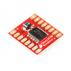
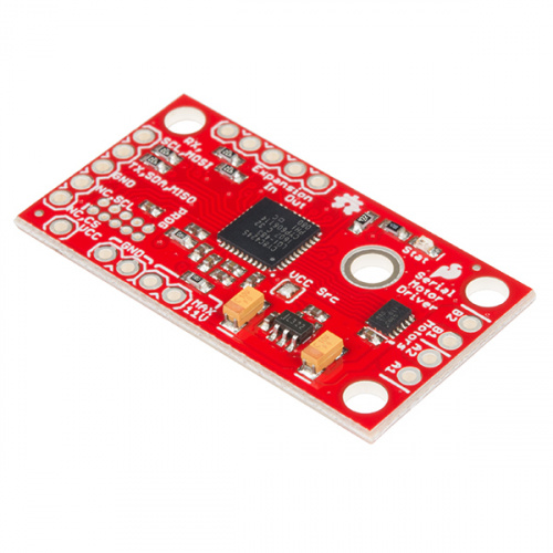
The Serial Controlled Motor Driver (abbreviated SCMD for the rest of this guide) is a DC motor driver that’s been designed to drive small DC motors with ease. It can be commanded by UART, I2C, or SPI communication, and it can drive a constant 1.2A load per motor (peak 1.5A) at 11V. Need more than two motors? Chain multiple SCMDs together and command them through the same serial interface. Need more current? Each board’s output can be bridged to allow double current.
In stock
ROB-13911
The SparkFun Serial Controlled Motor Driver (SCMD) is a DC motor driver that’s been designed to drive small DC motors with …
This driver board was designed to be affordable, compact and have more features than previous versions of serial-controlled motor drivers. Its main advantage is the variability of drive levels making fine control adjustments a possibility.
Features:
- 1.5 A peak drive per channel, 1.2 A steady state
- Operates from 3 to 11 volts with 12v absolute max
- 3.3v default VCC and logic
- Max VCC in of 5.5v
- 127 levels of DC drive strength.
- Controllable by I2C, SPI, or TTL UART signals
- Direction inversion on a per motor basis
- Global Drive enable
- Expansion port utilizing I2C, allows 16 additional drivers
- Exposed TO-220 heat sink shape
- Several I2C addresses, default UART bauds available
- Bridgeable outputs
- Optional fail-safe and diagnostics available.
- Configurable expansion bus bit rate to 50, 100, or 400 kHz.
- Configurable expansion bus update rate from 1ms to 255ms, or by command only
Covered In This Tutorial
This tutorial covers basic usage of the motor driver. It shows how to connect it to I2C, SPI, or UART at 3.3V levels, and how to attach more drivers to the master and control them all independently. It also shows some common motors that can be used without heatsinks.
Required Materials
This tutorial explains how to use the Serial Controlled Motor Driver Breakout Board with an Arduino or direct serial. To follow along, you’ll need the following materials:
In stock
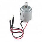
ROB-11696
This is our new Hobby Motor now with a 6mm, 10 tooth, gear to make your basic projects a little simpler to manage. It works w…
4In stock
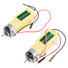
ROB-13302
These are a pair of hobby gearmotors from DAGU. These gearmotors are the same ones recommended for use in the Shadow Chassis …
28 available
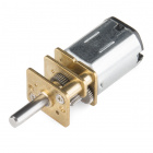
ROB-12429
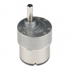
These micro gearmotors are incredibly tough and feature full metal gears. They have a gear ratio of 50:1 and operate up to 12…
15 available
ROB-12147
These standard gearmotors are incredibly tough and feature full metal gears to help you drive wheels, gears, or almost anythi…
1Check out our entire offering of DC motors:
DC Gearmotor Catalog
The SCMD is a 3.3V logic device! If you need to interface to 5V you'll need to use a logic level converter, or modify the SCMDs from stock to operate at 5V, and supply your own regulated 5V.
In stock
BOB-12009
If you've ever tried to connect a 3.3V device to a 5V system, you know what a challenge it can be. The SparkFun bi-directiona…
59Suggested Reading
If you aren’t familiar with the following concepts, we recommend you read over these tutorials before continuing.
Serial Communication
Asynchronous serial communication concepts: packets, signal levels, baud rates, UARTs and more!
I2C
An introduction to I2C, one of the main embedded communications protocols in use today.
Binary
Binary is the numeral system of electronics and programming...so it must be important to learn. But, what is binary? How does it translate to other numeral systems like decimal?
Logic Levels
Learn the difference between 3.3V and 5V devices and logic levels.
Hexadecimal
How to interpret hex numbers, and how to convert them to/from decimal and binary.
Terminology
This guide and related documentation uses a few terms with specific meanings. When User and Expansion are used, it is referring to the physical pins of the connection. When Master and Slave are used, it matches the I2C behavior on the expansion port, and refers to the connected chain of SCMDs.
- User Port– Connects the user’s project to the master SCMD and is unused on slaves.
- Expansion Port– Connects a single master and up to 16 slaves, and should never be connected to the user’s project.
- Master– The SCMD that is connected to the user’s project. Also, it is the I2C master on the expansion port
- Slave– A SCMD that is only connected to a master SCMD by way of the expansion port.
Note: The config in and out pins of the expansion port may sometimes be connected to the user’s project for error checking and mitigation purposes.
Motor Polarity– The driver and this document often omit motor polarity. This is because polarity to spin direction is not standardized, and it is assumed the user will attach them backwards 50% of the time. Each motor channel is independently configurable for what is thought of as ‘forward’ spin by command. It is assumed that the user will first attach the motors, then decide which channels need to be inverted and issue inversion settings at boot time.
Expansion Bus I2C Pull-Ups– All master SCMDs should have at least one set of pull-ups enabled for their expansion bus, even if no slaves are present! The board’s default state is disabled because pull-up resistors should be applied thoughtfully per design, but it means a single master without slaves will un-intuitively require the jumper to be closed.
Motor Numbering– The SCMD’s silkscreen shows connections for motor ‘A’ and motor ‘B’ to prevent confusion within a programming environment where numbers are used to denote motors or drivers.
![alt text]()
Motor numbering scheme
When somethings refers to a ‘motor number’, the following scheme is used. The motor attached to the master at position ‘A’ will always be motor 0, and the ‘B’ position, motor 1. The first slave device attached will have motors 2, and 3, at positions ‘A’ and ‘B’ respectively. Slave 2 will have motors 4, and 5, and so on.
When a SCMD is designated as bridged mode, it loses whatever motor is attached to the ‘B’ position, and any information sent to control the ‘A’ position will control both outputs synchronously, such as inversion or drive strength.
This is not to be confused with ‘driver number’, which indicates which SCMD in the chain is being referenced.
Hardware Overview
This section describes the basic parts of the hardware.
![alt text]()
All of the components are populated on the top side of the board.
Power is supplied through the VIN Connection and is regulated down to 3.3V for the PSoC and logic circuits. A VCC rail pin is provided for hackability.
The Status LED has a few things that it displays simultaneously:
- Emits a blip when it receives data from the master.
- Flashes once every ~2.5 seconds to indicate nominal condition
- Flashes eight times per ~2.5 second period to indicate that the failsafe condition has occurred.
The User Port is designated for connection to the user’s project (which will tell the motors what to do), and can be configured as UART, SPI, or I2C by jumper setting.
The Expansion Port is configured as I2C master or slave based on jumper settings, and operates on a second I2C bus with only other motor drivers.
The microcontroller generates PWM signals that go straight to the DRV8835 motor driver, which consists of 2 mosfet H-bridge driver circuits with thermal and current protection built in.
![alt text]()
The bottom of the board contains user configuration jumpers and a large area to wick the heat.
Powering the SCMD
Provide 3.3V to 11V to “MAX 11V” and “GND”. Each has two through-holes for general use. They can be used to reduce connection resistance or to piggyback other devices, or can accept the leads of a large capacitor. The terminal is directly connected to the DRV8835’s power input, and is also regulated down to 3.3V for the PSoC supply and logic levels. The driver can consume up to 3A of current so make sure these wires are short or heavier gauge, or both.
When slaves are attached to the expansion port, they also require power from another source. Wire the “MAX 11V” and “3.3V” pins in parallel with the master as shown in (Expansion Port Usage)[https://learn.sparkfun.com/tutorials/serial-controlled-motor-driver-hookup-guide#expansion-port-usage]
The VCC pin is an advanced feature that can be used to operate the SCMD at a different voltage, but isn’t used for basic applications. See the SCMD Datasheet for more information.
Jumper Usage Table
There are 4 sets of jumpers to configure on this board. There are pull-up enables for both user (User PU) and expansion bus (Exp. PU, default not-pulled up), A VCC disconnect jumper (VCC Src) to remove all logic from the on-board regulator, and 4 config bits that select operational mode.
| Name | Description | Usage |
|---|
| VCC Src | Connects VCC rail (pin) to on-board regulator | Open to remove regulator from VCC rail. User must supply 1.8V to 5.5V to VCC pin |
| User PU | I2C pull-up enable for User Port | Close all three pads to connect 4.7k resistors to SDA and SCL of user port |
| Exp. PU | I2C pull-up enable for Expansion Port | Close all three pads to connect 4.7k resistors to SDA and SCL of expansion port. The expansion bus should have exactly one board with pull-ups enabled on it. A single master without slaves is technically a complete expansion bus, and thus the single master needs these jumper pads bridged. |
| Config | Serial and function selection | The config bits are 4 bits that form a configuration nybble. A closed jumper is a '1' and an open jumper is a '0'. See config table for more information. |
Config Bits Table
The configuration is set by encoding a number into the 4 config bits on the bottom of the board. Close a jumper to indicate a 1, or leave it open to indicate a 0. Use this table to see what the user port, address, and expansion port will become in each configuration.
| Pattern | Mode | User Port | User Address | Expansion Port |
|---|
| 0000 | UART at 9600 | UART | N/A | Master |
| 0001 | SPI | SPI | N/A | Master |
| 0010 | Slave | N/A | N/A | Slave |
| 0011 | I2C | I2C | 0x58 | Master |
| 0100 | I2C | I2C | 0x59 | Master |
| 0101 | I2C | I2C | 0x5A | Master |
| 0110 | I2C | I2C | 0x5B | Master |
| 0111 | I2C | I2C | 0x5C | Master |
| 1000 | I2C | I2C | 0x5D | Master |
| 1001 | I2C | I2C | 0x5E | Master |
| 1010 | I2C | I2C | 0x5F | Master |
| 1011 | I2C | I2C | 0x60 | Master |
| 1100 | I2C | I2C | 0x61 | Master |
| 1101 | UART at 57600 | UART | N/A | Master |
| 1110 | UART at 115200 | UART | N/A | Master |
| 1111 | N/A | Reserved | N/A | N/A |
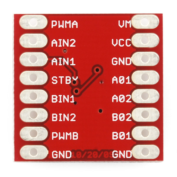
Pin Connections
The function of the 0.1" holes are explicitly indicated in this table, and are organized by physical location on the PCB.
| | | | Function / Connection |
|---|
| Group | Name | Direction | Description | UART | I2C | SPI |
|---|
| User Port | RX,SCL,MOSI | I | Multi-function Serial | Data In (RX) | SCL | MOSI |
|---|
| TX,SDA,MISO | IO | Multi-function Serial | Data Out (TX) | SDA | MISO |
| GND | - | Ground | Ground | Ground | Ground |
| NC,SCL | I | SPI clock | NC | NC | SCL |
| NC,CS | I | SPI chip select | NC | NC | CS |
| Expansion Port | GND | - | Ground | Slave bus Ground |
|---|
| SDA | IO | I2C Data line | Slave bus SCL |
| SCL | I | I2C Clock line | Slave bus SDA |
| In | I | Config In. Slave aquire-address/enable | Connects to upstream slave* |
| Out | O | Config Out. Enable next slave | Connects to downstream slave* |
| Motor Port | A1 | O | Winding of first addressable location | Motor A winding |
|---|
| A2 | O | Winding of first addressable location | Motor A winding |
| B1 | O | Winding of second addressable location | Motor B winding |
| B2 | O | Winding of second addressable location | Motor B winding |
| Power | GND | I | Main system ground (two pads) | Supply ground |
|---|
| MAX 11V | I | Motor driver raw voltage, regulator in (two pads) | Supply power |
| VCC | IO | Regulator output or user supplied VCC | NC |
Typical Application Motors and Heat Sinking
The SCMD is designed to operate small robot drive motors without a heatsink, up to about 500mA continuous current. Here’s how some regular motors fair when used.
- Hobby Gearmotor - 200 RPM (Pair)– RedBot style motors. These have low stall current and can be used without heatsinks.
- Micro Gearmotor - 460RPM– These can be used without heatsinks.
- Standard Gearmotor - 303RPM– Motors of this larger size can also be used without heatsinks.
- CPU fans – can be varied. Include a forward diode to prevent reverse voltage application. Some can draw a large amount of current! If the driver is getting too warm, a heatsink (or forced air) is required.
- Vacuum Pump - 12V– These pumps can draw amps. The driver will need to have heatsinking.
Determining if a heat sink is necessary
The temperature rise is related to the current load on the motor driver. To determine what your load is, attach the motor directly to a power supply and apply torque as will be done by the final application. Then use the chart below to determine if you need to heat sink. You can also stall the motor completely and measure the stall current (or use a multimeter to check the coil resistance, then do the math).
![alt text]()
Temperature rise as a function of total driver load
This graph shows total current sourced by the SCMD from both channels. If using bridged mode, find your target current load on the X axis, then see what to expect from these configurations on the Y axis. If not using bridged mode, double the current of a single motor to find the worst case condition of both motors at max current, then use that instead.
The TO-220 Heat Sink and Theragrip Thermal Tape were used to make the above graph, and work well to give yourself an extra amp of capability in a typical application.
Example 1: Interactive UART control with slaves.
This example demonstrates the basic commands, plus some direct register access possible with only a UART available. This type of program could be easily run from a script from a more classic PC where I2C or SPI isn’t available.
User port as UART
Requirements
- Computer serial terminal set to 9600 baud.
- Terminal set to send CR and LF (Carriage return and line feed).
- Config jumpers set to ‘0000’, or all open.
- Exp. PU jumper fully closed
- A 5V wall supply
Connect the FTDI to the SCMD using the diagram in “Hardware Connections”, and power the SCMD from the wall supply. Attach two motors to the driver, one between A1 and A2, and the other between B1 and B2.
![alt text]()
A SCMD ready to drive motors from UART command.
![alt text]()
The master is configured as UART (“0000”), and has pull up resistors enabled for the expansion bus.
Connections
Connect the FTDI basic to the motor drvier as follows. Notice that the both sides have RX that indicates data in, so the RX-TX serial lines must be crossed.
![alt text]()
Typing should now echo back to your terminal, pressing return should generate a new line (or error message), and commands can be entered. Skip forward to the UART Commands, or, enter the following commands as a guided tour. You may notice some responses like “inv” and “ovf” if the data entered was no good.
Example Commands
When you’re ready, send the following commands:
“R01”
This will read the ID register and return 0xA9
“M01F50”
This will tell motor 0 to drive at half speed, forward – But nothing will happen yet!
“E”
This will enable all drivers. Motor 0 should begin spinning at half speed.
“M01R100”
This will tell motor 1 to drive at full speed backwards. Now both should be spinning opposite directions.
“M01S”
This will cause motor 1 to reverse “forward” direction. Both should be spinning in the same direction now.
“E”
E again will disable both motors, which will stop spinning.
See the section “UART Commands” for a full command listing.
UART Commands
General:
The command parser is built to accept short strings of ascii data, compacted to reduce data transfer size while being easy to handle by standard UART hardware. The general form is a letter indicating which operation to perform followed by a series of numbers and letters, and finally a carriage return and line feed. As a string, an example command would be “M0F50\r\n”.
Return codes:
Overflow (“ovf”): The input buffer is filled (no command should be that long). Send delimiter to clear buffer
Invalid Syntax (“inv”): The first character in the command is not one of the defined prefixes.
Formatting Error (“fmt”): There was something generally wrong with the command, like it had the wrong number of characters or an out of range value was detected.
No Motor (“nom”): The motor’s number is past the most downstream slave detected.
Commands:
Help:
"H" or "?"
Prints command reference to serial.
Example:
"H\r\n"– Drive master motor B forward at 34%.
Drive motor:
"Mndl"
n = motor number, single or double digits
d = direction, R or F
l = level, 0 to 100
Example:
"M1F34\r\n"– Drive master motor B forward at 34%.
"M2R80\r\n"– Drive slave motor A reverse at 80%.
Invert motor polarity:
"MnI"
n = motor number, single or double digits
Example:
"M1I\r\n"– Invert the polarity of motor 1.
Clear motor inversion:
"MnC"
n = motor number, single or double digits
Example:
"M1C\r\n"– Set polarity of motor 1 to default.
Enable and disable Drivers"E" and "D"
The drivers boot in the disabled state so that other settings can be configured before beginning to drive the motors. Use these commands to enable and disable them.
Example:
"E\r\n"– Enable all outputs
"D\r\n"– Disable all outputs
Bridge and un-bridge outputs
"Brr" and "Nrr"
rr = Motor driver number, 0 is master, 1-16 is slave
This causes a motor driver to start or stop synchronous PWM on both ‘A’ and ‘B’ ports. Notice that the input is by board number, not motor number.
Example:
"B0\r\n"– Bridge master’s outputs"B2\r\n"– Bridge the 2nd physical slave’s outputs (motors 4&5)"N0\r\n"– Un-bridge master’s outputs"N2\r\n"– Un-bridge the 2nd physical slave’s outputs (motors 4&5)
Change the Baud Rate
"Un"
n = baud rate selection
This command changes the bitrate of the UART. The serial terminal will need to be reconfigured after this command. The command reports new rate at old baud before changing to the new one.
Rates supported:
1 – 2400
2 – 4800
3 – 9600
4 – 14400
5 – 19200
6 – 38400
7 – 57600
8 – 115200
Examples:
"U3\r\n"– Set baud rate to 9600
"U8\r\n"– Set baud rate to 115200
Write Register
"Wrrhh"
rr = two digit hex address
hh = two digit hex data
Example:
"W20FF\r\n"– Write 0xFF to register 0x20 (MA_DRIVE).
Read Register
"Rrr"
rr = two digit hex address
Example:
"R01\r\n"– Read address 0x01 (ID), bus will display “A9”, ID word of 0xA9
Arbitrary register access Some of the more intricate features like bus settings and debug information can be accessed by reading from a user-facing memory space, called registers. Use the
SCMD datasheet for mapping and function.
Arduino Library Reference
Example 2 and 3 use the Arduino IDE and a RedBoard to communicate with the SCMD. This section outlines how to get it and how the functions themselves operate.
Getting the Arduino Library
To get the Arduino library, download from Github, or use the Arduino Library Manager.
Download the Github repository
Visit the GitHub repository to download the most recent version of the library, or click the link below:
Download the Arduino Library
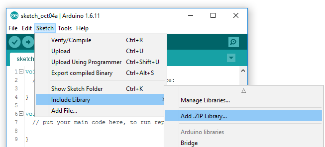
Use the library manager or install in the Arduino IDE
For help installing the library, check out our How To Install An Arduino Library tutorial.
If you don’t end up using the manger, you’ll need to move the SparkFun_Serial_Controlled_Motor_Driver_Arduino_Library folder into a libraries folder within your Arduino sketchbook.
Operating the Library
The library is made such that new motor driver object is constructed without parameters, the user populates the public settings structure, then calls .begin() to start the wire library and apply the communication settings.
Example:
language:c
SCMD myMotorDriver; //This creates an instance of SCMD which will be bound to a single master.

void setup()
{
    myMotorDriver.settings.commInterface = I2C_MODE; //or SPI_MODE
    myMotorDriver.settings.I2CAddress = 0x5A;
    myMotorDriver.settings.chipSelectPin = 10;
    myMotorDriver.begin();
}
Settings
The main SCMD class has a public member which is named settings. To configure settings, use the format myMotorDriver.settings.I2CAddress = (...); then call .begin() to apply.
settings contains the following members:
- uint8_t commInterface – Set equal to I2C_MODE or SPI_MODE
- uint8_t I2CAddress – Set to address that master is configured to in case of I2C usage
- uint8_t chipSelectPin – Set to chip select pin used on Arduino in case of SPI
Classes and Structures
There are a few classes used in the library. The main class is called SCMD, which is the object that talks to the motor drivers. There are also a couple structs in use – SCMDSettings and SCMDDiagnostics. A SCMDSettings object named settings is present within the SCMD class for configuration.
SCMD
SCMD is used to declare a single chain of motor drivers at specified port and modes in settings. The contained functions are described in a later section.
language:c
class SCMD
{
public:
    //settings
    SCMDSettings settings;
    SCMD( void );

    uint8_t begin( void );
    ... (Other functions...)

    uint16_t i2cFaults; //Location to hold i2c faults for alternate
    driver
};
SCMD Settings
SCMDSettings is an type for the settings member of SCMD. It is declared public to be configured by the user.
language:c
struct SCMDSettings
{
public:
    //Main Interface and mode settings
    uint8_t commInterface;
    uint8_t I2CAddress;
    uint8_t chipSelectPin;
};
SCMD Diagnostics
SCMDDiagnostics contains a bunch of 8 bit values of data for use with getDiagnostics and getRemoteDiagnostics. Declared objects are passed as a reference to the diagnostic function and written by the collected data.
language:c
struct SCMDDiagnostics
{
public:
    //Attainable metrics from SCMD
    uint8_t numberOfSlaves = 0;
    uint8_t U_I2C_RD_ERR = 0;
    uint8_t U_I2C_WR_ERR = 0;
    uint8_t U_BUF_DUMPED = 0;
    uint8_t E_I2C_RD_ERR = 0;
    uint8_t E_I2C_WR_ERR = 0;
    uint8_t LOOP_TIME = 0;
    uint8_t SLV_POLL_CNT = 0;
    uint8_t MST_E_ERR = 0;
    uint8_t MST_E_STATUS = 0;
    uint8_t FSAFE_FAULTS = 0;
    uint8_t REG_OOR_CNT = 0;
    uint8_t REG_RO_WRITE_CNT = 0;
};
Functions
uint8_t begin( void );
Call after providing settings to start the wire library, apply the settings, and get the ID word (return value should be 0xA9). Don’t progress unless this returns 0xA9!
bool ready( void );
This function checks to see if the SCMD is done booting and is ready to receive commands. Use this after .begin(), and don’t progress to your main program until this returns true.
bool busy( void );
This function checks to see if the SCMD busy with an operation. Wait for busy to be clear before sending each configuration commands (not needed for motor drive levels).
void enable( void );
Call after .begin(); to allow PWM signals into the H-bridges. If any outputs are connected as bridged, configure the driver to be bridged before calling .enable();. This prevents the bridges from shorting out each other before configuration.
void disable( void );
Call to remove drive from the H-bridges. All outputs will go low.
void reset( void );
This resets the I2C hardware for Teensy 3 devices using the alternate library, and nothing otherwise.
void setDrive( uint8_t channel, uint8_t direction, uint8_t level );
This sets an output to drive at a level and direction.
- channel: Motor number, 0 through 33.
- direction: 1 or 0 for forward or backwards.
- level: 0 to 255 for drive strength.
void inversionMode( uint8_t motorNum, uint8_t polarity );
This switches the perceived direction of a particular motor.
- motorNum: Motor number, 0 through 33.
- polarity: 0 for normal and 1 for inverted direction.
void bridgingMode( uint8_t driverNum, uint8_t bridged );
This connects any board’s outputs together controlling both from what was the ‘A’ position.
- driverNum: Number of connected SCMD, 0 (master) to 16.
- bridged: 0 for normal and 1 for bridged.
void getDiagnostics( SCMDDiagnostics &diagObjectReference );
This returns a diagnostic report from the master.
- &diagObjectReference: Pass a local SCMDDiagnostics object that will be written into.
void getRemoteDiagnostics( uint8_t address, SCMDDiagnostics &diagObjectReference );
This returns a diagnostic report from a slave.
- address: address of intended slave. This starts at 0x50 for the first slave and goes up from there.
- &diagObjectReference: Pass a local SCMDDiagnostics object that will be written into.
void resetDiagnosticCounts( void );
Clears the diagnostic counts of a master.
void resetRemoteDiagnosticCounts( uint8_t address );
Clears the diagnostic counts of a slave.
- address: address of intended slave. This starts at 0x50 for the first slave and goes up from there.
uint8_t readRegister(uint8_t offset);
Returns the contents of a memory location of the master.
- offset: Memory address to read.
void writeRegister(uint8_t offset, uint8_t dataToWrite);
Writes data to a memory location of the master.
- offset: Memory address to write.
- dataToWrite: Data to write to that address.
uint8_t readRemoteRegister(uint8_t address, uint8_t offset);
Returns the contents of a memory location of a slave.
- address: address of intended slave. This starts at 0x50 for the first slave and goes up from there.
- offset: Memory address to read.
void writeRemoteRegister(uint8_t address, uint8_t offset, uint8_t dataToWrite);
Writes data to a memory location of a slave.
- address: address of intended slave. This starts at 0x50 for the first slave and goes up from there.
- offset: Memory address to write.
- dataToWrite: Data to write to that address.
Example 2: RedBot Retrofit (I2C control)
This example drives a robot in left and right arcs, driving in an overall wiggly course. It demonstrates the variable control abilities. When used with a RedBot chassis, each turn is about 90 degrees per drive.
Requirements
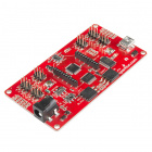
- SparkFun RedBoard or Arduino compatible 328p device
- The Arduino Library
- Config jumpers set to address 0x5A, or ‘0101’, or positions 0 and 2 closed with 1 and 3 open. Other addresses can be selected by using the bit patters of 0x3 to 0xE, and appropriate address programmed into the 328p code.
- User PU jumper fully closed
- Exp. PU jumper fully closed
The 328p is now ready to communicate with the SCMD. Skip forward to the Arduino Library section for API usage, or use one of the example sketches.
![alt text]()
This Shadow Chassis has been Red-trofitted with a RedBoard and SCMD
![alt text]()
The connections made are shown here.
Connections
Connect the Arduino basic to the motor drvier as follows. The SDA and SCL pins are pulled up by the SCMD only, and should idle at 3.3V.
![alt text]()
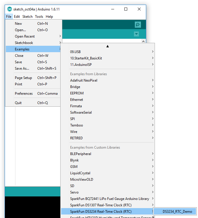
Example Code
The example, also available from the drop-down menu in Arduino (It’s called TwoMotorRobot), is as follows:
language:c
//This example drives a robot in left and right arcs, driving in an overall wiggly course.
//  It demonstrates the variable control abilities. When used with a RedBot chassis,
//  each turn is about 90 degrees per drive.
//
//  Pin 8 can be grounded to disable motor movement, for debugging.

#include <Arduino.h>
#include <stdint.h>
#include "SCMD.h"
#include "SCMD_config.h" //Contains #defines for common SCMD register names and values
#include "Wire.h"

SCMD myMotorDriver; //This creates the main object of one motor driver and connected slaves.

void setup()
{
  pinMode(8, INPUT_PULLUP); //Use to halt motor movement (ground)

  Serial.begin(9600);
  Serial.println("Starting sketch.");

  //***** Configure the Motor Driver's Settings *****//
  //  .commInter face can be I2C_MODE or SPI_MODE
  myMotorDriver.settings.commInterface = I2C_MODE;
  //myMotorDriver.settings.commInterface = SPI_MODE;

  //  set address if I2C configuration selected with the config jumpers
  myMotorDriver.settings.I2CAddress = 0x5A; //config pattern "0101" on board for address 0x5A

  //  set chip select if SPI selected with the config jumpers
  myMotorDriver.settings.chipSelectPin = 10;

  //*****initialize the driver get wait for idle*****//
  while ( myMotorDriver.begin() != 0xA9 ) //Wait until a valid ID word is returned
  {
    Serial.println( "ID mismatch, trying again" );
    delay(500);
  }
  Serial.println( "ID matches 0xA9" );

  //  Check to make sure the driver is done looking for slaves before beginning
  Serial.print("Waiting for enumeration...");
  while ( myMotorDriver.ready() == false );
  Serial.println("Done.");
  Serial.println();

  //*****Set application settings and enable driver*****//

  //Uncomment code for motor 0 inversion
  //while( myMotorDriver.busy() );
  //myMotorDriver.inversionMode(0, 1); //invert motor 0

  //Uncomment code for motor 1 inversion
  while ( myMotorDriver.busy() ); //Waits until the SCMD is available.
  myMotorDriver.inversionMode(1, 1); //invert motor 1

  while ( myMotorDriver.busy() );
  myMotorDriver.enable(); //Enables the output driver hardware

}

#define LEFT_MOTOR 0
#define RIGHT_MOTOR 1
void loop()
{
  //pass setDrive() a motor number, direction as 0(call 0 forward) or 1, and level from 0 to 255
  myMotorDriver.setDrive( LEFT_MOTOR, 0, 0); //Stop motor
  myMotorDriver.setDrive( RIGHT_MOTOR, 0, 0); //Stop motor
  while (digitalRead(8) == 0); //Hold if jumper is placed between pin 8 and ground

  //***** Operate the Motor Driver *****//
  //  This walks through all 34 motor positions driving them forward and back.
  //  It uses .setDrive( motorNum, direction, level ) to drive the motors.

  //Smoothly move one motor up to speed and back (drive level 0 to 255)
  for (int i = 0; i < 256; i++)
  {
    myMotorDriver.setDrive( LEFT_MOTOR, 0, i);
    myMotorDriver.setDrive( RIGHT_MOTOR, 0, 20 + (i / 2));
    delay(5);
  }
  for (int i = 255; i >= 0; i--)
  {
    myMotorDriver.setDrive( LEFT_MOTOR, 0, i);
    myMotorDriver.setDrive( RIGHT_MOTOR, 0, 20 + (i / 2));
    delay(5);
  }
  //Smoothly move the other motor up to speed and back
  for (int i = 0; i < 256; i++)
  {
    myMotorDriver.setDrive( LEFT_MOTOR, 0, 20 + (i / 2));
    myMotorDriver.setDrive( RIGHT_MOTOR, 0, i);
    delay(5);
  }
  for (int i = 255; i >= 0; i--)
  {
    myMotorDriver.setDrive( LEFT_MOTOR, 0, 20 + (i / 2));
    myMotorDriver.setDrive( RIGHT_MOTOR, 0, i);
    delay(5);
  }
}
The example works by configuring the motor driver, then using for loops to ramp up and down the motor drive levels.
Things to note:
- begin is periodically ran until the returned ID word is valid.
- Setup waits for isReady() to become true before going on to the drive section
- One motor is inverted by command at setup. Do it here so you don’t have to mess with it later.
- enable() is called to connect the drivers to the PWM generators.
- LEFT_MOTOR and RIGHT_MOTOR are defined to ease use of the setDrive( … ) function.
Example 3: Two slaves, 5 motors, 1 bridged (SPI control)
This demonstrates more advanced usage of the serial driver. Here, we have a couple slaves attached, with one being configured as a bridged mode. This is a good example of how the motor numbering scheme works.
Requirements
![alt text]()
The motor drivers are connected on a breadboard for test.
![alt text]()
The master is configured as SPI (“0001”), and has pull up resistors enabled for the expansion bus.
![alt text]()
Slaves boards should be set to “0010” with no pull up resistors enabled, as the master is doing it.
Connections
Connect the Arduino and Level Shifter to the motor drvier as follows. This connects to the standard SCL, MOSI, and MISO positions, and uses pin 10 as a chip select.
![alt text]()
The user port connections for this example
While this example will operate with only a master, add slaves to the expansion port to get the full experience.
The expansion port allows multiple SCMDs to be run from the same I2C address, SPI select line, or UART instance. The port can support up to 16 SCMDs set as slave by a common I2C interface, and daisy-chained config-in to config-out wiring
![alt text]()
A diagram showing the expansion bus usage
Notice that the expansion I2C lines are connected to a common bus while the config lines are connected from one board’s ‘Out’ to the next’s ‘In’. More slaves can be added onto the end of the chain.
![alt text]()
The expansion bus connections
When power is applied, the master will assign addresses to the slaves. This may take a couple seconds. When complete, the slaves should all have a faintly lit, blinking status LED indicating communication.
Example Code
The example, also available from the drop-down menu in Arduino (It’s called DriverChainWithBridging), is as follows:
language:c
//This example demonstrates some of the more advanced usage of the motor driver.
//It uses 3 motor drivers, with the master attached as SPI.  One slave is bridged,
//and the sketch test drives each motor. (There will be a break when the overtaken motor
//channel is activated.)
//
//This also shows how to count the number of connected slaves and report, as well as
//arbitrary register access.

#include <Arduino.h>
#include <stdint.h>
#include "SCMD.h"
#include "SCMD_config.h" //Contains #defines for common SCMD register names and values
#include "Wire.h"

//#defines

//Variables
//***** Create the Motor Driver object*****//
SCMD myMotorDriver;

void setup()
{
  Serial.begin(9600);

  Serial.println("Starting sketch.");

  //***** Configure the Motor Driver's Settings *****//

  //  .commInter face can be I2C_MODE or SPI_MODE
  myMotorDriver.settings.commInterface = I2C_MODE;
  //myMotorDriver.settings.commInterface = SPI_MODE;

  //  set address if I2C configuration selected with the config jumpers
  myMotorDriver.settings.I2CAddress = 0x5A; //config pattern "0101" on board for address 0x5A
  //  set chip select if SPI selected with the config jumpers
  myMotorDriver.settings.chipSelectPin = 10;

  delay(2500); //Give the serial driver time to check for slaves

  //  initialize the driver and enable the motor outputs
  uint8_t tempReturnValue = myMotorDriver.begin();
  while ( tempReturnValue != 0xA9 )
  {
    Serial.print( "ID mismatch, read as 0x" );
    Serial.println( tempReturnValue, HEX );
    delay(500);
    tempReturnValue = myMotorDriver.begin();
  }
  Serial.println( "ID matches 0xA9" );

  Serial.print("Waiting for enumeration...");
  while ( myMotorDriver.ready() == false );
  Serial.println("Done.");

  //  Report number of slaves found
  uint8_t tempAddr = myMotorDriver.readRegister(SCMD_SLV_TOP_ADDR);
  if ( tempAddr >= START_SLAVE_ADDR )
  {
    Serial.print("Detected ");
    Serial.print(tempAddr - START_SLAVE_ADDR + 1); //Top address minus bottom address + 1 = number of slaves
    Serial.println(" slaves.");
  }
  else
  {
    Serial.println("No slaves detected");
  }

  //Configure bridging modes
  myMotorDriver.bridgingMode( 1, 1 ); //( DriverNum 1, bridged state = 1 )  This will bridge the first slave

  //Uncomment to set inversion

  //myMotorDriver.inversionMode(0, 1); //invert master, channel A
  //myMotorDriver.inversionMode(1, 1); //invert master, channel B
  //myMotorDriver.inversionMode(2, 1); //invert slave 1, channel A
  //    no need to configure motor 3, this position does nothing because the slave is bridged.
  //myMotorDriver.inversionMode(4, 1); //invert slave 2, channel A
  //myMotorDriver.inversionMode(5, 1); //invert slave 2, channel B

  //Enable the motors.
  myMotorDriver.enable();

  pinMode(8, INPUT_PULLUP);

}

void loop()
{
  //***** Operate the Motor Driver *****//
  //  This walks through all 34 motor positions driving them forward and back.
  //  It uses .setDrive( motorNum, direction, level ) to drive the motors.
  //
  //  Notice that when i == 3, no motor spins.  This position is made inactive by bridging the first slave.
  Serial.println("Now stepping through the motors.");
  for (int i = 0; i < 6; i++)
  {
    Serial.print("Driving motor ");
    Serial.println(i);

    myMotorDriver.setDrive( i, 1, 255); //Drive motor i forward at full speed
    delay(1000);
    myMotorDriver.setDrive( i, 0, 255); //Drive motor i backward at full speed
    delay(1000);
    myMotorDriver.setDrive( i, 1, 0);
  }
}
The example works by counting through the 6 motor positions and commanding them forward, then back.
Things to note:
- Only a single SCMD object is used, all slaves are accessed through the master.
- begin is periodically ran until the returned ID word is valid.
- Setup waits for isReady() to become true before going on to the drive section
- Slaves are counted by directly accessing the registers. ALL_CAPS_VALUES are #defined in SCMD_config.h.
- bridgingMode( … ) is called to bridge, by number of motor driver (master is driver 0).
- Motor 3 is excluded because the channel gets connected to motor 2 by brdiging. Though it can still be commanded, it will have no effect.
- enable() is called to activate the motors. This happens after the bridging configuration is set to protect the drivers.
Resources and Going Further
Advanced Features
The advanced features such as configuring the fail safe, data rates, diagnostic features, and bridging can be found in the following document. Use a PDF viewer that supports bookmarks for easiest navigation.
Not covered in this guide:
- VCC breakable to allow up to 5.5v levels.
- PSoC programming port.
- Bus diagnostic reporting
- Configurable failsafe time and operation
- Configurable expansion bus bitrate to 50, 100, or 400 kHz.
- Configurable expansion bus update rate from 1ms to 255ms, or by command only.
Additional Examples
There are also some additional examples packaged with the library which are not described here. Have a look at them and the arduino library source files to better understand the advanced usage.
Arduino examples not covered in this guide:
- RegisterRWTool – Use to convert ascii communication from a Arduino window into direct register access.
- Run-timeDiagnostics – Demonstrates reading the diagnostic registers and using the built-in diagnostic structure for data storage.
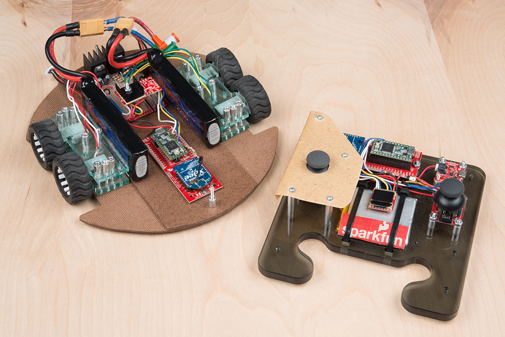
Robot examples available by github repo XbeeTeensyXCVR:
These robots are built using the serial controlled motor driver, with an XBee link.
Check out more robot action in the SCMD demo video:
For more motor-driving action, check out these other great SparkFun tutorials:
Experiment Guide for RedBot with Shadow Chassis
This Experiment Guide offers nine experiments to get you started with the SparkFun RedBot. This guide is designed for those familiar with our SparkFun Inventors Kit and want to take their robotics knowledge to the next level.
learn.sparkfun.com |CC BY-SA 3.0
| SparkFun Electronics | Niwot, Colorado