The SparkFun 16-Pin SSOP to DIP Adapter is a small PCB that lets you adapt 14 and 16-pin SSOP packages to a DIP footprint. These are useful for modding and upgrading devices that use 16-pin DIP ICs, when the upgraded IC is only available in a SSOP footprint. You can also use it for prototyping, to make SSOP packages compatible with solderless breadboards.
The updated version of this adapter comes as a dual array of PCBs – if you’re adapting one chip, you’re likely to adapt more than one. The PCBs easily snap apart, resulting in two individual boards.
The SSOP-16 land pattern on the board has also been improved from its predecessor. First, the SSOP and DIP pin numbering matches – both packages count counterclockwise from their respective pin 1. The board also fits in a standard 0.3" wide DIP footprint. The pads are very long, to accomodate 3.9mm, 4.4mm and 5.3mm package widths. They are on 0.635mm centers, but, with careful installation, an IC with 0.65mm leads will also fit. The board is contained entirely within the DIP outline, for situations with no extra clearance around the IC. Finally, if you leave two pads disconnected, SSOP-14 packages also fit.
Old Vs New
Suggested Reading
Check out any of the links below, if you are unfamiliar with a given topic.
The array of boards was scored when it was manufactured. If you bend along the scores, the boards snap apart easily.
Snap Apart
Prepare To Solder
It’s easiest to solder the IC in place before you mount the headers, so you don’t have to work around the protruding pins.
If this is your first time soldering surface mount ICs, patience and a steady hand are the key to good solder joints.
Neatness Counts – you want to put on enough solder to join the legs to the pads, but not so much that adjacent legs are accidentally bridged.
Work Quickly – if you leave the hot soldering iron on the board too long, you risk burning the traces and pads off the board. You want the iron at a temperature where the solder flows almost immediately when you apply it to the iron. Somewhat counter-intuitively, a hotter iron can be less damaging than a cooler one – having the iron at a hotter temperature allows you to work more quickly, reducing the potential for damage.
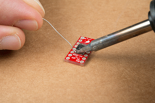
Solder IC In Place
To install the IC, we’ll be using a technique known as “drag soldering.” In drag soldering, we drag a blob of solder across the IC pins, depositing some on each as it goes by. If there’s too much solder after dragging, we’ll remove it with wick.
Before we show you how to drag solder, we want to emphasize the need for flux before starting, and the likelihood that you'll need some solder wick to clean up excess solder.
First, apply flux to the PCB. Flux cleans off the thin layer of oxidation the forms on the pads and allows molten solder to flow onto them.
Applying Flux.
Pin 1 of the IC is usually marked with a small dimple or notch in the IC body. Line these marks up with the corresponding marks in the PCB silkscreen. The silkscreen actually has three marks: a notch at one end of the IC, a dot within the IC outline, and a dot just outside the IC (which remains visible once the IC is soldered down).
To get started, flow a tiny bit of solder onto pads on opposite corners of the SSOP footprint.
Solder on opposing corners.
Grab the IC with the tweezers, and orient it over the footprint. Reheat one of the solder blobs from the previous step so the IC lead adheres to it. The solder should flow onto the IC legs, tacking the part in place. Press the IC down flat before the solder cools.
Then repeat this on the opposite leg, to hold the IC in place for the rest of the soldering operation.
Corners tacked in place.
When it’s in place, doublecheck that the rest of the pins are reasonably aligned with their pads. If the placement needs adjustment, reheat one corner, and move the IC.
If you’re careful and have a dainty soldering iron, you can proceed around the chip, soldering down each lead individually.
Of course, we’re not especially dainty. The tip of our iron is gigantic compared to the lead pitch of an SSOP, so we’re going to use a different technique, known as drag soldering.
To start drag soldering, heat a pin with the iron, then flow a blob of solder onto it. Once the solder flows, use the iron to drag the blob across the remaining leads.
Drag Soldering.
As you drag the blob, it will adhere each pin to the corresponding pad.
When you reach the end of the line of pins, there might be some blob remaining, and there will probably be some excess solder bridging adjacent pins.
Excess between leads.
Use the solder wick to clean these up.
.
Repeat the process down the other side of the IC.
When you’re done, take a moment to inspect your work. Check that each lead has a solder fillet to the pad underneath and that leads aren’t shorted to their neighbors. It gets harder to touch things up once the pins have been soldered on.
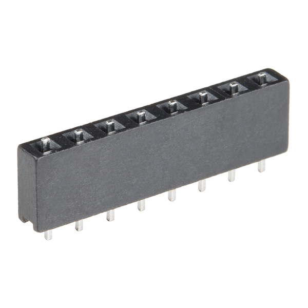
Solder In Header Pins
With the IC in place, now you can solder on the pins. We’ll demonstrate using both plain break-sway headers and flip pins. Flip-pins are special pins that are the size and shape of regular DIP-IC legs. They fit in breadboards and IC sockets better than plain square-pin headers.
Regular Headers
Soldering in regular headers is easier if you have a jig that can hold the pins while you solder. It turns out that a solderless breadboard has a bunch of holes with the proper alignment!
Start by breaking 8-pin segments off the header. Insert them into the breadboard, two rows apart.
Pin in Breadboard
Set the PCB over the headers. Take care to keep the pins aligned straight up and down.
PCB On Pins
Work your way around the PCB, soldering each pin from the top of the board.
Flip Pins
Flip pins come packaged in a black plastic shroud, which keeps them aligned until they have been installed. The shroud also works as an assembly jig.
Flip Pins.
To start, stand two sets of flip pins up on your workbench. Then place the PCB on top of the pins. The tail on flip pins is as long as the PCB is thick – they won’t protrude above the PCB.
Assembling flip pins.
Work your way around the board, soldering in each pin. Take care to keep the pins aligned perpendicular to the plane of the bench top. Once the pins have been soldered on, carefully slide the plastic pin aligner off, revealing the IC-type pins.
Revealing the pins.
Deflux
Once you’ve finished soldering, look at the solder joints. If they appear to have a yellow or brown coating on or around them, the board has flux residue (under a magnifying glass, it might look like amber or burnt sugar). Flux is acidic and can cause problems with long-term reliability, so it’s best to clean it off.
You’ll have to check the documentation for your solder for the proper cleaning methodology. Some flux is water soluble, while some requires a solvent like isopropyl alcohol or acetone.
Defluxing.
Verify
Before we jump into applications of the SSOP-to-DIP adapter board, let’s take a moment to doublecheck our work.
A quick visual inspection can help spot solder bridges or solder joints that didn’t flow properly. It’s also a good time for one last check, to make certain that pin one of the SSOP is properly oriented.
For a little extra confidence, you can also use a multimeter in continuity mode to verify that the legs of the SSOP are connected to the pads but not bridged to their neighbors.
Continuity check.
Using The Adapter
Adapter Orientation
The pins of the DIP footprint are rotated 90° in relation to the pins of the SSOP. We covered the pin-1 markings for the SSOP in the assembly section.
Pin 1 of the DIP footprint is marked two ways. The solder pad for pin 1 is square, while the others are round. It also has a small 1 in the silkscreen near the pad.
Pin markings, top
Pins 1 and 9 are also marked in the legend silkscreened on the bottom of the board.
Pin markings, bottom
Case Studies
On a Breadboard
This adapter is useful when you want to build a breadboard prototype using a chip that’s only available in SSOP. It allows the chip to properly fit the rows of the breadboard.
Breadboard Example
Upgrading Old Devices
Another common use of a SSOP-to-DIP adapter is upgrading or modifying existing equipment…or, as in this case, saving your bacon when you’ve purchased components with the wrong footprint.
We’re working on restoring an old SparkFun Function Generator Kit, and needed a 74HC04 logic chip. When we ordered it, we didn’t read the description carefully enough, and we got a 14-pin SSOP IC, and need to fit it into a DIP footprint on the board. Thankfully, we’ve got an adapter board to help.
14 pins in a 16-pin adapter.
If you look closely, you’ll notice two things in the above photo: first, the IC only has 14 pins, on a 16-pin adapter board. Second, it is a wider SSOP package than we’ve seen in the other examples. Thankfully, the land pattern on the PCB has extra-long pads to accomodate it.
-Installed in socket.-
Since the PCB already had a socket, we opted to use flip pins on the adapter. We’re fitting a 14-pin chip on a 16-pin adapter, so we opted to keep pin-1 aligned on both pieces. This also means that the chip is two pins short – we’re not using pins 8 and 9 on the adapter, and pins 10 through 16 on the adapter are off by two, connected to IC pins 8 to 14.
The Wireless Joystick Kit provides an easy way to control your next XBee project. Before the Wireless Joystick, radio controlled projects used hobby RC transmitters, the same that are used for RC cars, boats, and planes. The problem with these transmitters is many aren’t customizable, and the ones that are, tend to be too expensive for many of us. The Wireless Joystick aims to bring a custom wireless solution for those that want to control their project the way they want to, not the way they’re forced to.
The following is not provided in the kit and will need to be purchased separately.
Picking the right battery depends on the use, but we recommend using at least a 400 mAh battery. If you’ve never used Xbee before, it’s also recommended to use a Series 1 XBee, or check out our XBee buying guide.
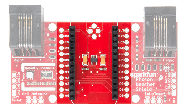
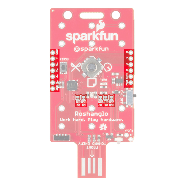
Wireless Joystick Board Overview
The Wireless Joystick board comes with the following:
SAMD21 Microcontroller
Adjustable battery charger (500mA max charge rate)
MAX17043G LiPo fuel gauge
Programmable LED connected to D13
Two trigger buttons
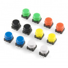
Room for 2 Thumb Joysticks, or 1 Thumb Joystick and 4 push buttons
Hardware Hookup
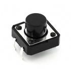
The first step is to solder in the right angle tactile buttons. These are meant to inserted from the bottom the board and soldered to the top layer of PCB. This will look like the image below.
The way the rest of the board is soldered really depends on what it will be used for. There are few different configurations for the joystick(s) and buttons. Read on to see he different configurations.
Dual Joysticks
In this configuration, the Wireless Joystick uses both joysticks and is perfect for tank steering robots. Tank steering maps the vertical position of the left and right joysticks to the speed and direction of the left and right motors of a robot. After soldering in the joysticks, the board should look like this:
Single Joystick
In this configuration, the Wireless Joystick uses a single joystick on the left and 4 of our 12mm momentary pushbuttons on the right. This setup is similar to what older console game consoles used. After soldering in the joystick and switches, the Wireless Joystick board will look like the image below.
A quick tip about soldering the joystick(s): Sometimes during shipping, the pins on the joystick can be bend slightly. Before trying to insert the pins to the board, make sure all of the pins look straight and run parallel with the others. When soldering the joysticks, start with the pins on the vertical and horizontal potentiometers, and use a pair of tweezers to motivate the pins into place and work my way to the select button.
Mounting the battery
To secure the battery to the board, we recommend using a small piece of foam double sided tape. We’ve found the easiest place to put the battery is under the right joystick. Before mounting the battery, make sure to trim the the joystick solder joints to avoid puncturing the battery!
Setting the Battery Charge Rate
By default, the charge rate is set to the maximum rate of 500mA. If you’re battery is larger than 500mAh, you can skip ahead to the Arduino Examples section. If you’re using less than a 500mAh battery, you should solder in the appropriate resistor that we’ll determine below.
The life of a lithium battery is dependent on a few factors: number of charge/discharge cycles, charge/discharge rate, battery temperature, as well as a few others. When charging a lithium battery, it’s recommended not to exceed a 1C charge rate. For example, if you have a 400mAh battery, your current to charge the battery should not exceed 400mA. To change the rate, change the solder jumper so that the middle and R_PROG pads are shorted and solder in the appropriate resistor. To calculate the right resistor, use the equation below:
R_PROG = 1000 / I_PROG
R_PROG = Resistor value in kohms
I_PROG = Desired current value in mA
To charge the battery, simply plug in the micro USB cable, and move the switch to the OFF position. If your charge rate is below 200mA, the board should charge without issue regardless of the power switch position. Faster charge rates may require the switch to be off to cut current to everything but the charging circuit if charging from a computer’s USB port or small USB chargers.
Arduino Examples
Now that the hardware is all set, lets look at some software examples. Before we get started though, make sure you have both the Arduino SAMD and the Sparkfun SAMD board definitions installed. If you need some help with this, check out the SAMD21 Mini/Dev Breakout Hookup Guide .
Tank Steering Motor Controller Example
For our first example, let’s try controlling a robot using tank steering. To use tank steering, you’ll need to solder in both joysticks. This examples uses the following parts.
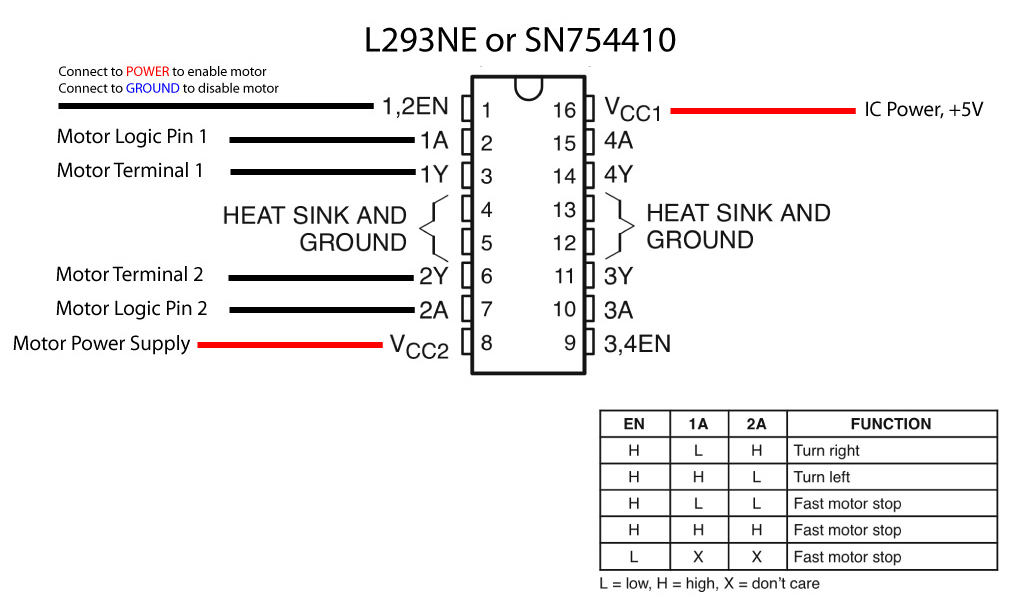
To connect everything, start by soldering the “+” pin of the male deans connector to the motor driver pin that says “MAX 11V” as well as to the 5V pin on the XBee Explorer. Connect the “-” pin of the male deans connector to “GND” on both the motor driver, and XBee Explorer. Next we’ll connect the “DOUT” pin of the explorer to the “RX” pin of the motor driver. Solder the motors to the B1/B2 and A1/A2, but be sure the solder the second motor opposite of the first, so that they’ll both be spinning in the same direction. The wheels attach to the motors with a friction fit, so carefully push those onto the motor’s D-shaft. Finally, attach the XBees to the Wireless Joystick, as well as the to the Xbee Explorer.
Adding the Code to the Wireless Joystick
Now that we have everything wired up and soldered together, let’s put some code on the Wireless Joystick! To use this example, copy the code below to the Arduino IDE. Make sure you select the SparkFun SAMD21 Dev Breakout as your board.
language:c
/* Wireless Joystick Tank Steering Robot Example
 * by: Alex Wende
 * SparkFun Electronics
 * date: 9/28/16
 *
 * license: Creative Commons Attribution-ShareAlike 4.0 (CC BY-SA 4.0)
 * Do whatever you'd like with this code, use it for any purpose.
 * Please attribute and keep this license.
 *
 * This is example code for the Wireless Joystick to control a robot
 * using XBee. Plug the first Xbee into the Wireless Joystick board,
 * and connect the second to the SparkFun Serial Motor Driver.
 *
 * Moving the left and right joystick up and down will change the
 * speed and direction of motor 0 and motor 1. The left trigger will
 * reduce the maximum speed by 5%, while the right trigger button
 * will increase the maximum speed by 5%.
 *
 * Connections to the motor driver is as follows:
 * XBee - Motor Driver
 *   5V - VCC
 *  GND - GND
 * DOUT - RX
 *
 * Power the motor driver with no higher than 11V!
 */

#define L_TRIG 6        // Pin used for left trigger
#define R_TRIG 3        // Pin used for right trigger
#define L_JOYSTICK A3   // Pin used for left joystick
#define R_JOYSTICK A0   // Pin used for right joystick

int8_t speedLevel = 20; //Maximum speed (%) = speedLevel * 5 (units are percent)

void setup() {
  Serial1.begin(9600); // Start serial communication with XBee at 9600 baud
  delay(10);

  Serial1.print("W7001\r\n"); // Set the bit in enable register 0x70 to 0x01

  pinMode(L_TRIG,INPUT_PULLUP); // Enable pullup resistor for left trigger
  pinMode(R_TRIG,INPUT_PULLUP); // Enable pullup resistor for right trigger
}

void loop() {
  int16_t leftStick, rightStick;    // We'll store the the analog joystick values here
  char buf0[10],buf1[10]; // character buffers used to set motor speeds

  // Reduce top speed
  if(digitalRead(L_TRIG) == 0)
  {
    speedLevel -= 2;
    if(speedLevel < 2) speedLevel = 2;
    while(digitalRead(L_TRIG) == 0)
    {
      delay(2);
    }
  }
  // Increase top speed
  if(digitalRead(R_TRIG) == 0)
  {
    speedLevel += 2;
    if(speedLevel > 20) speedLevel = 20;
    while(digitalRead(R_TRIG) == 0)
    {
      delay(2);
    }
  }

  // Read joysticks
  // Convert analog value range to motor speeds (in %)
  leftStick = (5-(analogRead(L_JOYSTICK)/93))*speedLevel;
  rightStick = (5-(analogRead(R_JOYSTICK)/93))*speedLevel;

  // Build motor 0 buffer
  if(leftStick > 0)
  {
    sprintf(buf0,"M0F%d\r\n",leftStick);
  }
  else
  {
    sprintf(buf0,"M0R%d\r\n",abs(leftStick));
  }

  // Build motor 1 buffer
  if(rightStick > 0)
  {
    sprintf(buf1,"M1F%d\r\n",rightStick);
  }
  else
  {
    sprintf(buf1,"M1R%d\r\n",abs(rightStick));
  }

  // Send motor speeds
  delay(5);
  Serial1.print(buf0);
  delay(5);
  Serial1.print(buf1);
}
Plug in the battery to power the motor driver and receiving XBee and turn on the Wireless Joystick. Moving the left stick should move the left motor, and the right stick should move the right motor. If your left stick is controlling the right motor (or visa versa), swap the pin values for the L_JOYSTICK and R_JOYSTICK at the top of the sketch.
You can slow down the speed of the motors by pressing the left trigger button, and speed up the motor by pressing the right trigger button.
USB Example
In order to program a microcontroller from a computer, many microcontrollers like the ATMega328, require another IC to bridge USB to the microcontroller’s UART. Other microcontrollers, like the SAMD21 used on the Wireless Joystick, come with native USB, which means there isn’t any need for the bridge IC. Having native USB allows us to program the microcontroller and imitate USB devices like keyboards, mice, and gaming joysticks.
In this example, we’ll program the Wireless Joystick to help us play a classic game, Asteroids. This example can use either the dual joystick or the single joystick configuration. Let’s first upload the code below to our board by copying and pasting it into the Arduino IDE. Make sure you select the SparkFun SAMD21 Dev Breakout as your board. After the code has finished transferring to board, go back to the webpage that has the game on it. Click start and try it out!
language:c
/* Not So Wireless Wireless Joystick USB Example
 * by: Alex Wende
 * SparkFun Electronics
 * date: 9/28/16
 *
 * license: Creative Commons Attribution-ShareAlike 4.0 (CC BY-SA 4.0)
 * Do whatever you'd like with this code, use it for any purpose.
 * Please attribute and keep this license.
 *
 * This example sends ASCII arrow key characters over USB when the left
 * joystick is moved or a space character when right trigger button is pressed.
 */

#include "Keyboard.h"

#define H_JOYSTICK    A2
#define V_JOYSTICK    A3
#define R_TRIGGER     3

void setup() {
  pinMode(R_TRIGGER, INPUT_PULLUP);
  Keyboard.begin();
}

void loop() {
  uint16_t hStick = analogRead(H_JOYSTICK);
  uint16_t vStick = analogRead(V_JOYSTICK);

  if(hStick > 766) Keyboard.press(KEY_LEFT_ARROW);
  else if(hStick < 255) Keyboard.press(KEY_RIGHT_ARROW);
  else{
    Keyboard.release(KEY_RIGHT_ARROW);
    Keyboard.release(KEY_LEFT_ARROW);
  }

  if(vStick > 766) Keyboard.press(KEY_UP_ARROW);
  else{
    Keyboard.release(KEY_UP_ARROW);
  }

  if(digitalRead(R_TRIGGER) == LOW){
    Keyboard.press(' ');
  }
  else{
    Keyboard.release(' ');
  }
}
You can find a free version of Asteroids here. The controls are pretty simple, you can use the left joystick to rotate your rocketship left and right as well as to accelerate forward. To destroy the asteroids, you press the right trigger button.
Battery Monitoring Example
In this example we’ll program the Wireless Joystick to print out information about our battery, such as the remaining charge and the current battery voltage. This example also makes use of the programmable LED to indicate when our battery is running low and it’s time to recharge. To use this example, copy the code below to the Arduino IDE. Make sure you select the SparkFun SAMD21 Dev Breakout as your board.
language:c
/* Wireless Joystick battery monitoring Example Code
  by: Jim Lindblom and modified by Alex Wende
  SparkFun Electronics
  date: 9/28/16

  license: Creative Commons Attribution-ShareAlike 4.0 (CC BY-SA 4.0)
  Do whatever you'd like with this code, use it for any purpose.
  Please attribute and keep this license.

  This is example code for the MAX17043G chip on the Wireless Joystick.
  The MAX17043G+U is a compact, low-cost 1S LiPo fuel gauge.
  The SAMD21 talks with the MAX17043 over an I2C (two-wire) interface,
  so we'll use the Wire.h library to talk with it.

  It's a silly example. It reads the battery voltage, and its percentage
  full and prints it out over SerialUSB. You probably wouldn't care about
  the battery voltage if you had the Wireless Joystick connected via USB.
  But this code does show you how to configure the MAX17043G, and how to
  read and manipulate the voltage values.
*/
#include <Wire.h>

#define MAX17043_ADDRESS 0x36  // R/W =~ 0x6D/0x6C

// Pin definitions
int alertPin = 7;  // This is the alert interrupt pin, connected to pin 7 on the Wireless Joystick

// Global Variables
float batVoltage;
float batPercentage;
int alertStatus;

void setup()
{
  pinMode(alertPin, INPUT_PULLUP);

  SerialUSB.begin(9600);  // Start hardware SerialUSB
  delay(500);
  SerialUSB.println("Hello World");

  Wire.begin();  // Start I2C
  configMAX17043(32);  // Configure the MAX17043's alert percentage
  qsMAX17043();  // restart fuel-gauge calculations
}

void loop()
{
  batPercentage = percentMAX17043();
  batVoltage = (float) vcellMAX17043() * 1/800;  // vcell reports battery in 1.25mV increments
  alertStatus = digitalRead(alertPin);

  SerialUSB.print(batPercentage, 2);  // Print the battery percentage
  SerialUSB.println(" %");
  SerialUSB.print(batVoltage, 2);  // print battery voltage
  SerialUSB.println(" V");
  SerialUSB.print("Alert Status = ");
  SerialUSB.println(alertStatus, DEC);
  SerialUSB.println();
  delay(1000);
}

/*
vcellMAX17043() returns a 12-bit ADC reading of the battery voltage,
as reported by the MAX17043's VCELL register.
This does not return a voltage value. To convert this to a voltage,
multiply by 5 and divide by 4096.
*/
unsigned int vcellMAX17043()
{
  unsigned int vcell;

  vcell = i2cRead16(0x02);
  vcell = vcell >> 4;  // last 4 bits of vcell are nothing

  return vcell;
}

/*
percentMAX17043() returns a float value of the battery percentage
reported from the SOC register of the MAX17043.
*/
float percentMAX17043()
{
  unsigned int soc;
  float percent;

  soc = i2cRead16(0x04);  // Read SOC register of MAX17043
  percent = (byte) (soc >> 8);  // High byte of SOC is percentage
  percent += ((float)((byte)soc))/256;  // Low byte is 1/256%

  return percent;
}

/*
configMAX17043(byte percent) configures the config register of
the MAX170143, specifically the alert threshold therein. Pass a
value between 1 and 32 to set the alert threshold to a value between
1 and 32%. Any other values will set the threshold to 32%.
*/
void configMAX17043(byte percent)
{
  if ((percent >= 32)||(percent == 0))  // Anything 32 or greater will set to 32%
    i2cWrite16(0x9700, 0x0C);
  else
  {
    byte percentBits = 32 - percent;
    i2cWrite16((0x9700 | percentBits), 0x0C);
  }
}

/*
qsMAX17043() issues a quick-start command to the MAX17043.
A quick start allows the MAX17043 to restart fuel-gauge calculations
in the same manner as initial power-up of the IC. If an application's
power-up sequence is very noisy, such that excess error is introduced
into the IC's first guess of SOC, the Arduino can issue a quick-start
to reduce the error.
*/
void qsMAX17043()
{
  i2cWrite16(0x4000, 0x06);  // Write a 0x4000 to the MODE register
}

/*
i2cRead16(unsigned char address) reads a 16-bit value beginning
at the 8-bit address, and continuing to the next address. A 16-bit
value is returned.
*/
unsigned int i2cRead16(unsigned char address)
{
  int data = 0;

  Wire.beginTransmission(MAX17043_ADDRESS);
  Wire.write(address);
  Wire.endTransmission();

  Wire.requestFrom(MAX17043_ADDRESS, 2);
  while (Wire.available() < 2)
    ;
  data = ((int) Wire.read()) << 8;
  data |= Wire.read();

  return data;
}

/*
i2cWrite16(unsigned int data, unsigned char address) writes 16 bits
of data beginning at an 8-bit address, and continuing to the next.
*/
void i2cWrite16(unsigned int data, unsigned char address)
{
  Wire.beginTransmission(MAX17043_ADDRESS);
  Wire.write(address);
  Wire.write((byte)((data >> 8) & 0x00FF));
  Wire.write((byte)(data & 0x00FF));
  Wire.endTransmission();
}
Using the Extra GPIO
You may have noticed that the SPI, I2C, and other GPIO pins have been broken out. We wanted to breakout the unused pins to allow for any customization that you may want. In this final example, we’ll use the OLED screen to display battery information from the MAX17043 fuel gauge.
Before we look at the code, let’s wire up the OLED Breakout. You’ll need seven wires to connect the OLED Breakout to the Wireless Joystick, their connections are:
Wireless Joystick - OLED Breakout
3.3V - 3V3
GND - GND
MOSI - SDI
SCK - SCK
D10 - CS
D11 - RST
D12 - D/C
Where you place the OLED screen is up to you, but I personally like to use foam doubled sided tape to mount the display on the top of the board by the USB connector.
To use the code below, you’ll want to download the MicroOLED Arduino library first. To download the libary, click the button below, or grab the latest version from our GitHub repository. For more information on how to use the libary, visit the Micro OLED Breakout Hookup Guide.
After installing the library, copy the code below to the Arduino IDE. Make sure you select the SparkFun SAMD21 Dev Breakout as your board.
language:c
/* GPIO Example For the Wireless Joystick
 * by: Alex Wende
 * SparkFun Electronics
 * date: 9/28/16
 *
 * license: Creative Commons Attribution-ShareAlike 4.0 (CC BY-SA 4.0)
 * Do whatever you'd like with this code, use it for any purpose.
 * Please attribute and keep this license.
 *
 * This example the SparkFun OLED Breakout (LCD-13003) to display
 * the battery's voltage and remaining charge.
 *
 * Connections:
 * Wireless Joystick - OLED
 * 3.3V - 3V3
 *  GND - GND
 * MOSI - SDI
 *  SCK - SCK
 *  D12 - D/C
 *  D11 - RST
 *  D10 - CS
 */

#include <SPI.h>
#include <Wire.h>
#include <SFE_MicroOLED.h>

#define PIN_RESET 11  // Connect RST to pin 9 (req. for SPI and I2C)
#define PIN_DC    12  // Connect DC to pin 8 (required for SPI)
#define PIN_CS    10 // Connect CS to pin 10 (required for SPI)
#define DC_JUMPER 0

#define MAX17043_ADDRESS 0x36

// Pin definitions
int alertPin = 7;  // This is the alert interrupt pin, connected to pin 7 on the Wireless Joystick
int ledPin = 13;   // This is the pin the led is connected to

// Global Variables
float batVoltage;
float batPercentage;
int alertStatus;

MicroOLED oled(PIN_RESET, PIN_DC, PIN_CS);

void setup()
{
  oled.begin();  // Start OLED
  Wire.begin();  // Start I2C

  pinMode(alertPin, INPUT_PULLUP);  // Enable pullup resistor
  pinMode(ledPin, OUTPUT);
  configMAX17043(32);  // Configure the MAX17043's alert percentage
  qsMAX17043();  // restart fuel-gauge calculations

  oled.setFontType(0);  // Set the text to small (10 columns, 6 rows worth of characters)
}

void loop()
{
  batPercentage = percentMAX17043();  // Get battery percentage
  batVoltage = (float) vcellMAX17043() * 1/800;  // vcell reports battery in 1.25mV increments
  alertStatus = digitalRead(alertPin);

  oled.clear(PAGE); // clears the screen
  oled.setCursor(0,0);  // move cursor to top left corner
  oled.print(batPercentage, 2);
  oled.println(" %\n");

  oled.print(batVoltage, 2);
  oled.println(" V\n\n");

  oled.print("VBAT : ");
  if(alertStatus == LOW){
    digitalWrite(ledPin, HIGH);
    oled.print("LOW");
  }
  else{
    digitalWrite(ledPin, LOW);
    oled.print("OK");
  }
  oled.display();
  delay(10);
}

/*
vcellMAX17043() returns a 12-bit ADC reading of the battery voltage,
as reported by the MAX17043's VCELL register.
This does not return a voltage value. To convert this to a voltage,
multiply by 5 and divide by 4096.
*/
unsigned int vcellMAX17043()
{
  unsigned int vcell;

  vcell = i2cRead16(0x02);
  vcell = vcell >> 4;  // last 4 bits of vcell are nothing

  return vcell;
}

/*
percentMAX17043() returns a float value of the battery percentage
reported from the SOC register of the MAX17043.
*/
float percentMAX17043()
{
  unsigned int soc;
  float percent;

  soc = i2cRead16(0x04);  // Read SOC register of MAX17043
  percent = (byte) (soc >> 8);  // High byte of SOC is percentage
  percent += ((float)((byte)soc))/256;  // Low byte is 1/256%

  return percent;
}

/*
configMAX17043(byte percent) configures the config register of
the MAX170143, specifically the alert threshold therein. Pass a
value between 1 and 32 to set the alert threshold to a value between
1 and 32%. Any other values will set the threshold to 32%.
*/
void configMAX17043(byte percent)
{
  if ((percent >= 32)||(percent == 0))  // Anything 32 or greater will set to 32%
    i2cWrite16(0x9700, 0x0C);
  else
  {
    byte percentBits = 32 - percent;
    i2cWrite16((0x9700 | percentBits), 0x0C);
  }
}

/*
qsMAX17043() issues a quick-start command to the MAX17043.
A quick start allows the MAX17043 to restart fuel-gauge calculations
in the same manner as initial power-up of the IC. If an application's
power-up sequence is very noisy, such that excess error is introduced
into the IC's first guess of SOC, the Arduino can issue a quick-start
to reduce the error.
*/
void qsMAX17043()
{
  i2cWrite16(0x4000, 0x06);  // Write a 0x4000 to the MODE register
}

/*
i2cRead16(unsigned char address) reads a 16-bit value beginning
at the 8-bit address, and continuing to the next address. A 16-bit
value is returned.
*/
unsigned int i2cRead16(unsigned char address)
{
  int data = 0;

  Wire.beginTransmission(MAX17043_ADDRESS);
  Wire.write(address);
  Wire.endTransmission();

  Wire.requestFrom(MAX17043_ADDRESS, 2);
  while (Wire.available() < 2)
    ;
  data = ((int) Wire.read()) << 8;
  data |= Wire.read();

  return data;
}

/*
i2cWrite16(unsigned int data, unsigned char address) writes 16 bits
of data beginning at an 8-bit address, and continuing to the next.
*/
void i2cWrite16(unsigned int data, unsigned char address)
{
  Wire.beginTransmission(MAX17043_ADDRESS);
  Wire.write(address);
  Wire.write((byte)((data >> 8) & 0x00FF));
  Wire.write((byte)(data & 0x00FF));
  Wire.endTransmission();
}
Resources and Going Further
Here are a few helpful links that might help answer any question you may still have regarding the Wireless Joystick:
This Experiment Guide offers nine experiments to get you started with the SparkFun RedBot. This guide is designed for those familiar with our SparkFun Inventors Kit and want to take their robotics knowledge to the next level.
Learn how to connect the RedBot Line Following Sensor Bar to an arduino type microcontroller. Use the example sketches to read data from the bar, and try out a simple line following algorithm.
In this project, we’ll create a wearable pin using conductive thread to connect a LilyPad LED to a battery holder. Follow along by drawing your own design on a piece of fabric, or download and print one of SparkFun’s designs.
White Felt (you will need at least 3 square inches)
Pin Back
Don't have a LilyPad Sewable Electronics Kit? You can follow along with this project using this wish list of individual LilyPad pieces. You will need to source your own felt and pin back (available at local craft stores) to complete the project.
Printer if you are downloading and printing one of SparkFun’s pin designs
Planning Your Project
For this project, we’ll be using the Glowing Pin template (download below or use the template included with your kit). If needed, download and print the provided template. We've also provided some color and black and white designs to use with printable fabric for the top layer of the pin. Right-click the images below and choose “Save Link As” to download the template to your computer.
Right-click and choose “Save Link As” or click image to download PDF
Printable Fabric Designs:
Right-click and choose “Save Link As” or click image to download PDF
After downloading a design, follow the directions on the package of your printable fabric to print them out. Feel free to create a larger pin by scaling the downloadable designs, if you’d like more room to work with or for a real statement piece.
Trace the pin template on white felt and cut out. We’ll be building our circuit on the felt piece, then adding a decorative layer of fabric with designs on top of it. Trace and cut a slightly larger circle or SparkFun design out of thin fabric (or design your own out of felt) for the top layer of the pin.
Understanding Your Circuit
This project is an example of a basic circuit– an electrical loop that travels from a power source along a path (called a trace) to a component (or components) that uses the electricity to function, and then back to the power source. For our project, we’ll use an LED (Light-Emitting Diode). When this loop is completed by stitching the pieces together with conductive thread traces, electricity from the power source is able to flow from the positive (+) side of the battery through to the LED (lighting it up) and back to the negative (–) side of the battery. This electric flow is called current. As you build projects with LilyPad pieces, you will learn different ways to design conductive thread circuits and experiment with additional pieces that help control or use the flow of electricity.
In this circuit, the LED is installed facing the fabric to shine through the other side. Other LilyPad projects may use LEDs facing outward from the fabric.
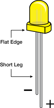
Take a look at the LED and battery holder. Notice that the silver sew tabs are labeled either positive or negative. Many electronic components have polarity, meaning electric current can only flow through them in one direction.
If hooked up incorrectly, they will not light up. The batteries in this kit are also polarized; they have a positive and negative side. Always check the labels on LilyPad pieces to make sure they are correctly oriented before sewing together a circuit.
Arranging Your Circuit
Don't put your battery in yet.
Position the battery holder with the ON/OFF switch to the left side and the bottom two sew tabs close to the bottom edge of the felt. Use a small dot of hot glue in the center of the holder to attach it to the felt, as shown. Gluing the battery holder on this way leaves room for placing the LilyPad LED on the felt.
Remember: Glue is great for keeping your components in place, but it can interfere with your circuit. Try to keep glue clear of sew tabs.
While planning the LED’s placement, note that it will need to be slightly above the center or toward the top half of the fabric so it doesn’t touch or overlap the battery holder.
If you are using one of SparkFun’s pre-made designs, hold the design over the felt, and use a fabric marker or chalk to mark where the LED should be placed to shine through. Gather one LED (snap off of an LED panel if needed).
For this project only, we’ll place the LED with the lens facing the felt, allowing it to shine through to the other side. The back of the LED has a cursive L, which should be facing you. For the rest of the projects in the LilyPad Sewable Electronics Kit, we’ll install the LED with the lens up (away from the felt).
Before attaching the LED, rotate it so the (+) and (–) symbols on the LED board align with the (+) and (–) symbols on the battery holder’s sew tabs. Use a small dab of hot glue on the center of the front of the board to secure to the felt. Be careful not to cover the holes with glue – we’ll need those to sew through later.
Stitching It Together
If you need help sewing with conductive thread, this tutorial covers the basics.
STEP 1:
Cut a long piece of conductive thread, thread the needle, and tie a knot at the end. Now, it’s time to connect the LED to the battery holder with the conductive thread. One line of stitching will connect the positive (+) side of the battery holder to the positive end of the LED. A second line of stitching will connect the negative (–) sides of the boards and complete the circuit.
STEP 2:
Finish your first line of stitching by tying a finishing knot on the sew tab and trimming your excess thread.
Don’t forget! You’ll need to tie a new knot at the end of your thread before you begin the next section of stitching.
STEP 3:
Repeat the process with a new piece of thread to connect the negative side of the battery holder to the negative end of the LED. Be careful not to let the stitches touch the path used for the positive connections, as that would cause a short circuit. Trim any thread tails before testing. Now, the circuit is complete!
Installing Your Battery and Testing
Insert the coin cell battery with the positive side facing up, labeled as (+), into the opening on the battery holder across from the ON/OFF switch. Turn on the switch to allow current to flow through the circuit. Turn off the switch when not in use to prolong battery life.
How to place a battery in a LilyPad Battery Holder..
Troubleshooting
With any electronics project, there are times you will have to troubleshoot if your circuit isn’t working. If your circuit isn’t lighting up, try a new battery or check that your project is switched on. Check your sewing for any loose threads or ends that may be touching other parts of your circuit and causing a short circuit. Learn more about troubleshooting your project in the LilyPad Basics: E-Sewing tutorial.
Finishing Touches
Always remove your battery when working on your project to avoid damaging your components.
With the battery removed, use a hot glue gun or thread to attach your fabric design over your felt circle so the LED shines through. Draw a design on the fabric, if you’d like (or see design templates in the Planning Your Project step). Turn the project over, and attach an adhesive pin back to finish up your wearable art!
Here are a few examples of creative glowing pins:
Resources and Going Further
Looking for another project? Let’s move on to Project 2: Illuminated Mask in the LilyPad Sewable Electronics Kit.
Ready to add some good vibes to your project? Look no further than the Haptic Motor Driver. This board breaks out Texas Instruments' DRV2605L haptic motor driver, which has some seriously cool features. Add meaningful feedback from your devices using the Haptic Motor Driver and an Arduino compatible device. This tutorial will get you up and running, or vibing, in no time with the I2C library for Arduino and example projects that give you the hardware setup and the code for various modes of operation.
Flexible Haptic and Vibration Driver for both ERM and LRA type motors
I2C Controlled Digital Playback Engine
Audio to Vibe
PWM input with 0% to 100% Duty-Cycle Control Range
Hardware Trigger Input
Built-in Waveform Sequencer and Trigger
And that is just to name a few. See the DRV2605L data sheet for a complete list.
Required Materials
You’ll need a handful of extra parts to get the Haptic Motor Driver up-and-running. Below are the basic components used in this tutorial, if you want to follow along.
A microcontroller that supports I2C is required to communicate with the DRV2605L and relay the data to the user by means of vibration. The SparkFun RedBoard or Arduino Uno are popular options for this role, but just about any microcontroller development board should work. (The firmware examples use an Arduino library, if that serves as any extra motivation to use an Arduino.)
The DRV2605L is designed for a handful of uses. The Technical Documents provided by Texas Instruments includes application notes, user guides, literature and blogs. The DRV2605L communicates over I2C. We’ve got a great library to make it easy to use. We’re going to be using a breadboard to connect the breakout board to the RedBoard. If these subjects sound foreign to you consider browsing through these tutorials before continuing on.
0.5mA - Important for your battery powered projects.
Pin Descriptions
The SparkFun Haptic Motor Driver - DRV2605L breakout board provides 6 pins to provide power to the sensor and I2C bus.
Pin Label
Description
GND
Connect to ground.
VCC
Used to power the DRV2605L Haptic Motor Driver. Must be between 2.0 - 5.2V
SDA
I2C data
SCL
I2C clock
IN
Analog and PWM signal input
EN
Enable pin. Connect to VCC for most applications.
O-
Negative motor terminal.
O+
Positive motor terminal.
Setting the Jumpers
On the front of the breakout board is a solder jumper:
I2C PU– This is a 3-way solder jumper that is used to connect and disconnect the I2C pullup resistors. By default, this jumper is closed, which means that both SDA and SCL lines have connected pullup resistors on the breakout board. Use some solder wick to open the jumper if you do not need the pullup resistors (e.g. you have pullup resistors that are located on the I2C bus somewhere else).
ERM and LRA Motors
The DRV2605L is capable to driving two different types of motors. So what are they? How do they work? How are they different?
Precision Microdrives published application notes on using both Eccentric Rotating Mass, ERM and Linear Resonant Actuator, LRA type motors. The default firmware for the DRV2605L is set for use with ERM type motors. There are six effects libraries for the ERM type and only one for LRA. If you want to get up and running quickly, I recommend our ERM type motor, otherwise you’ll be updating several registers in the device and spending much more time with the data sheet.
Photo courtesy of https://www.precisionmicrodrives.com/
Photo courtesy of https://www.precisionmicrodrives.com/
The difference between the two motors is how the movement of a mass is displaced. LRA vibration motors require an AC signal, driving a sine waveform that is modulated to get multiple effects. ERM vibration motors use a DC motor with a counter weight attached. The DC voltage controls the speed of the motor.
The ERM has an off-centre load, when it rotates the centripetal force causes the motor to move. The rotation is created by applying a current to the armature windings attached to the motor shaft. As these are inside a magnetic field created by the permanent magnets on the inside of the motor’s body, a force is created causing the shaft to rotate. To ensure the rotation continues in the same direction, the current in the windings is reversed. This is achieved by using static metal brushes at the motor terminals, which connect to a commutator that rotates with the shaft and windings. The different segments of the commutator connect to the brushes during rotation and the current is reversed, maintaining the direction of rotation.
In a similar method, LRAs use magnetic fields and electrical currents to create a force. One major difference is the voice coil (equivalent of the armature windings) remains stationary and the magnetic mass moves instead. The mass is also attached to a spring, which helps it return to the centre. Driving the magnetic mass up and down causes the displacement of the LRA and thereby the vibration force.1
To use the SparkFun Haptic Motor Driver, you will need some supporting software. If you use Arduino, then you are in luck! We created an Arduino Library that makes the DRV2605L easy to use. Click the button below to download the latest version of the Haptic Motor Driver project files, which includes the Arduino library.
The SparkFun DRV2605L library has every register defined, and simple functions can be called to create a custom haptic experience. Every register must be set (or use the default if that works for you). Use the data sheet to help you with the values that need to be written to the registers.
Going through the library header file, you’ll see just about every register has a comment with its function and corresponding page number in the data sheet. This board is capable of operating in seven modes and can use either an LRA or ERM type motors. There are three example sketches in the download folder using Internal Trigger mode, PWM mode and Audio-to-Vibe mode. From here it shouldn’t take much to get the device working in other modes.
This project was perfect for the season. What’s a better way to spend the day than in a recliner playing Ark: Survival Evolved riding a Stego with toasty toes and a foot massage? These are my heated house slippers.
These house slippers have a haptic motor and a heating pad in each foot giving me a gentle massage and keeping my feet warm.
Parts Needed
You will also need:
Pair of fuzzy slippers
Sewing needle
Thread
A handful of sew-on snaps
A pair of scissors
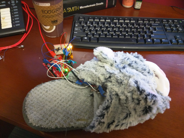
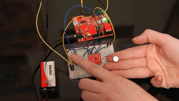
Hardware Hook-up
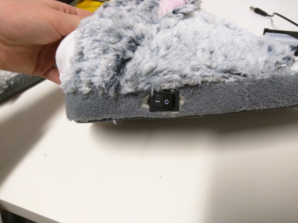
This is what the project looked like while it was being built. Start with a new pair of comfy slippers. Make the circuit on a breadboard, load the code and test it. I chose the haptic libraries that were the strongest and have it alternating between clicking, pulsing and alerting. You can customize your massage however you’d like. There are two switches included in this circuit, so you can use the Haptic Motor Driver independently of the heating element or both at one time. The LilyPad button switch controls the heat level on the heating pad. An LED will light up indicating a low, medium or high heat setting.
I chose these slippers because cats. And, also because the tops provided me with some room to store the electronics and battery.
Carefully cut the top off the slipper using a seam ripper and/or utility knife.
I laid out the parts so the vibration motor was in the center with the heating pad and the switch off to the side. I routed all the wires toward the toes and made a hole in the top so I could feed the wires into the cat’s head. Like this:
Wires gathered at toes
Here you can see the wires pulled through. You may need to remove some stuffing. I also sewed snaps along the opening for easy access to the electronics inside.
Switch on the side.
At this point test the circuit one more time to make sure wires weren’t disconnected when pulling them towards the front and through the top. Once you have verified the circuit works repeat the process for other slipper, sew it all back together and enjoy putting your feet up!
Arduino Sketch
To complete the project, upload the following code once your circuit is built.
language:c
//DIY Heated Massage Slippers
//Waveforms 16, 17 and 52 cycled to give your feet some TLC
//Use with ERM type Motors
//Try out other libraries (1-5, 7)
//and play around with the Loop Gain,
//BACKEMF gain, braking factor etc. in
//Feedback register through MotorSelect function

//Hardware Hookup
//Photoresitor to analog pin 0
//

#include <Sparkfun_DRV2605L.h>
#include <Wire.h>

SFE_HMD_DRV2605L HMD;
const int analogInPin = A0;  // Analog input pin that the sensor is attached to
const int analogOutPin = 9; // Analog output pin that the Haptic Motor Driver is attached to

int sensorValue = 0;        // value read from the sensor
int outputValue = 0;        // value output to the PWM (analog out)


void setup()
{
  HMD.begin();
  Serial.begin(9600);
  HMD.Mode(3); //PWM INPUT
  HMD.MotorSelect(0x0A);
  HMD.Library(7); //change to 6 for LRA motors

}
void loop()
{

 // read the analog in value:
  sensorValue = analogRead(analogInPin);
  // map it to the range of the analog out:
  outputValue = map(sensorValue, 0, 1023, 0, 255);
  // change the analog out value:
  analogWrite(analogOutPin, outputValue);

  // print the results to the serial monitor:
  Serial.print("sensor = ");
  Serial.print(sensorValue);
  Serial.print("\t output = ");
  Serial.println(outputValue);

  // wait 2 milliseconds before the next loop
  // for the analog-to-digital converter to settle
  // after the last reading:
  delay(2);
 }
PWM & Analog Input Mode Example: Light Vibes
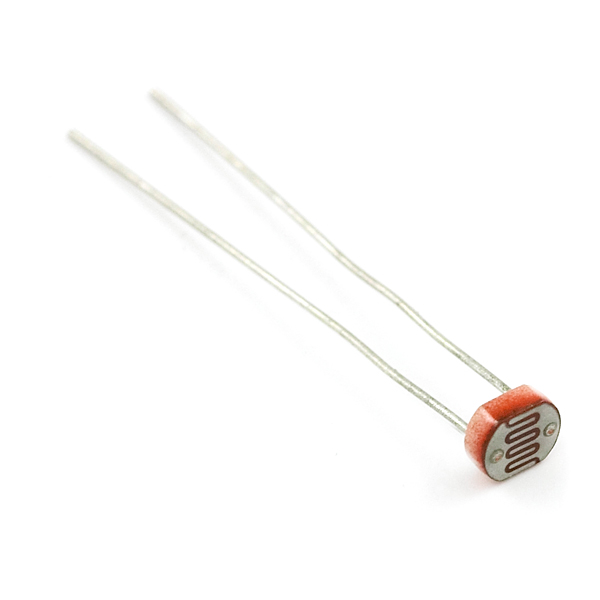
In this example project, we are going to control an ERM motor based on analog input from a photocell that gets mapped to a range from 0-255 and uses that result to set the pulse width modulation of an output pin connected to the IN/TRIG pin on the Haptic Motor Driver. This project will give haptic effects based on the amount of ambient light in an area.
Waving your hand over the photoresistor turns off the motor, and, when you move your hand away, you can feel the ramping effects as the PWM signal increases with the amount of light detected.
Parts Needed
In addition to the basics like hook-up wire, you’ll also need the following parts:
language:c
// Control the vibration of an ERM motor
// using PWM and a photoresistor.

#include <Sparkfun_DRV2605L.h>
#include <Wire.h>

SFE_HMD_DRV2605L HMD;
const int analogInPin = A0;  // Analog input pin that the sensor is attached to
const int analogOutPin = 9; // Analog output pin that the Haptic Motor Driver is attached to

int sensorValue = 0;        // value read from the sensor
int outputValue = 0;        // value output to the PWM (analog out)


void setup()
{
  HMD.begin();
  Serial.begin(9600);
  HMD.Mode(0x03); //PWM INPUT
  HMD.MotorSelect(0x0A);
  HMD.Library(7); //change to 6 for LRA motors

}
void loop()
{

 // read the analog in value:
  sensorValue = analogRead(analogInPin);
  // map it to the range of the analog out:
  outputValue = map(sensorValue, 0, 1023, 0, 255);
  // change the analog out value:
  analogWrite(analogOutPin, outputValue);

  // print the results to the serial monitor:
  Serial.print("sensor = ");
  Serial.print(sensorValue);
  Serial.print("\t output = ");
  Serial.println(outputValue);

  // wait 2 milliseconds before the next loop
  // for the analog-to-digital converter to settle
  // after the last reading:
  delay(2);
 }
Audio to Vibe Mode Example: Really Feel the Music
For this project, I wanted to create something inspired by the movie, Mr. Holland’s Opus. At the end of this movie, Mr. Holland puts on a show for his son who is deaf. Theatrical lights went off along with the music that was played. The movie made it seem like it was a great visual, but, if you muted the TV, it wasn’t anything special. I set out to create an immersive experience based on what you can feel alone. The motors would be aligned to the body in a way to feel low to high frequencies. Bass at the bottom near the ankles, and treble up top near the shoulders. Each motor is linked to a specific instrument in the Orchestra, and the vibration motor should mimic the signal going in. Can you feel a symphony? This is what I set to find out.
Unfortunately, obtaining isolated tracks of specific instruments in an orchestral piece has proven to be difficult. This experiemtn leaves room for improvement. Here’s the Audio-to-vibe example.
Parts Needed
In addition to the basics like hook-up wire, you’ll also need the following parts:
language:c
// Control the vibration of an ERM motor
// using an AC Coupled Audio Signal into the IN/TRIG pin

#include <Sparkfun_DRV2605L.h>
#include <Wire.h>

SFE_HMD_DRV2605L HMD;

void setup()
{
  HMD.begin();
  Serial.begin(9600);
  Serial.print("Audio to Vibe");
  HMD.Mode(0x04); //Audio INPUT
  HMD.cntrl1(0xB3); // Set the AC Couple bit in Control 1
  HMD.cntrl3(0x62); // Set the Analog bit in Control 3
  HMD.MotorSelect(0x0A);
  HMD.Library(7); //change to 6 for LRA motors

}
void loop()
{
}
Resources and Going Further
Now that you have been through three of modes of operation, try out the other four and use an LRA motor! How will you add haptics to your next project?
Here are are the numerous resources and documents mentioned through out this tutorial.
For this project, we’ll try individually controlling the LEDs in an e-textile circuit. We’ll explore two ways of controlling the flow of current to an LED using a button and switch while we craft a creative plush creature.
Felt (one 9"x12" sheet of craft felt will make one plush; use scraps of felt to add decorations)
Fiberfill Stuffing
Embroidery or Sewing Thread
Don't have a LilyPad Sewable Electronics Kit? You can follow along with this project using this wish list of individual LilyPad pieces. You will need to source your own felt, fiberfill stuffing, and embroidery or sewing thread (available at local craft stores) to complete the project.
You will also need:
Pen, marker, or chalk
Scissors
Hot glue gun (with extra glue)
Optional: Craft supplies for decorating (feathers, sequins, buttons, etc.)
Planning Your Project
For this project, we’ll be using the Light-Up Plush template (download below or use the template included with your kit). If needed, download and print the provided template. Right-click the image below and choose “Save Link As” to download the template to your computer.
Right-click and choose “Save Link As” or click image to download PDF
Trace and cut out the plush template shape on a piece of felt. To hide your stitches entirely, cut out an extra half-piece of felt (as shown) to place on top of your finished plush (see Finishing Touches).
The two halves of what will become your plush are connected at the “feet” to allow your entire circuit to be on one surface and to make stuffing the project easier. Don’t cut these two halves apart.
Working with ProtoSnap
If you are using individual LilyPad components instead of the E-Sewing ProtoSnap, you will not be able to follow along with the experiment in the next section exactly, but read along to learn more about buttons and switches.
We’ll use the LilyPad pieces in the circuit to turn different LEDs on and off. Using the E-Sewing ProtoSnap, we’ll examine how buttons and switches behave differently, then snap the pieces apart and build them into a plush creature with light-up features.
Before we arrange our circuit on the felt, with the battery installed, slide the battery holder switch to the ON position.
Don’t snap apart your E-Sewing ProtoSnap board quite yet. You’ll need it intact for a brief experiment first.
Understanding Your Circuit
Buttons and switches are electronic components that control the flow of electricity through a circuit. The circuit is closed when current is allowed through by turning on a switch or pressing a button. When a piece of the circuit is disconnected by turning a switch or button off, it is an open circuit.
LilyPad Slide Switch
The LilyPad Slide Switch has a small switch labeled ON/OFF. When the toggle is moved to the ON position, the two sew tabs on the switch are connected, allowing current to flow through and close the circuit. When moved to OFF, parts inside the switch move away from each other and open the circuit (disconnecting it). It helps to visualize switches as drawbridges for electricity – when the bridge is up (open), nothing can cross over. When it is down (closed), the pathway is reconnected, and electricity can flow along the original path.
LilyPad Button
The LilyPad Button Board is also a type of switch. When you press the button in the middle of the board, it connects the two sew tabs and allows current to flow through. When you let go of the button, the connection is opened again, and the button springs back into place. This button is an example of a momentary switch – it is only active when an action is applied.
This is slightly different from the slide switch, which is an example of a maintained switch, meaning its state remains the same until changed.
Learn more about buttons and switches in our Switch Basics tutorial.
Arranging Your Circuit
Carefully snap apart the connected components on the E-Sewing ProtoSnap panel. Discard the non-sewable pieces and scraps. You will end up with six LilyPad pieces: a battery holder with battery, three LEDs, a button, and a switch.
Always remove your battery when working on your circuit to avoid damaging your components.
Arrange the pieces on the felt according to the diagram below. Make sure to check the orientation of the LilyPad LEDs before you stitch them together. The positive tabs of the LED connect to the button or switch, and the negative tabs connect to the negative tab on the battery holder. When your circuit design is finalized, use a dab of glue on the back of each component to attach them to the felt.
For this project, we’ll be arranging the pieces slightly differently from on the E-Sewing ProtoSnap. To avoid any crossed conductive thread, we are connecting (+) with both the button and the switch instead of having two separate paths to the battery holder. When creating circuits with e-textiles, both the electrical properties of the circuit and aesthetic decisions are part of the design process.
This project has a lot of stitching. If you want to hide the stitches, use a layer of felt or decorations over the thread after you’ve finished your circuit (see Finishing Touches section), or use a hidden stitch (see our E-Sewing Basics tutorial).
Stitching It Together
If you need help sewing with conductive thread this tutorial covers the basics.
STEP 1:
Cut a long piece of conductive thread, thread the needle, and tie a knot at the end. Begin sewing at the positive sew tab on the battery holder closest to the fold or “feet” on the felt cutout. Remember to use three to four loops around each tab as you sew.
Use a running stitch or hidden stitch (see E-Sewing Basics for these techniques) to connect the positive sew tab on the battery board to the closest sew tab on the switch. Sew three to four loops around the switch’s sew tab to secure, then tie a knot and cut.
STEP 2:
With a new piece of thread, connect the other side of the switch to the positive sew tabs of the top two LEDs and end with three to four loops on the closest tab of the button. Tie and cut.
STEP 3:
With a new piece of thread, begin at the other side of the button and stitch three to four loops around the sew tab. Continue stitching to the positive side of the last LED, ending with three to four loops.
Tie and cut.
STEP 4:
Finally, we’ll stitch all the negative connections. With a new piece of thread, stitch three to four loops on the negative (–) sew tab of the first LED and connect to the negative tabs on the other LEDs, ending at the negative tab of the battery holder as shown. Make sure to loop three to four times on each connection.
After all the stitching is complete, turn the project over, and trim any loose thread tails before testing.
Installing Your Battery and Testing
Insert the coin cell battery into the battery holder with the positive (labeled +) side facing up. Test the button and switch to make sure the LEDs light up. If they do, remove the battery and continue to the Finishing Touches section.
How to place a battery in a LilyPad Battery Holder.
Troubleshooting
With any electronics project there are times you will have to troubleshoot if your circuit isn’t working. If your circuit isn’t lighting up, try a new battery or check that your project is switched on. Check your sewing for any loose threads or ends that may be touching other parts of your circuit and causing a short circuit. Learn more about troubleshooting your project in the LilyPad Basics: E-Sewing tutorial.
Finishing Touches
Always remove your battery when working on your project to avoid damaging your components.
Conductive thread can be part of the visual design, or hidden. To hide stitches, add a layer of felt on top with cutouts to allow the LEDs to shine through and to access the button and switch.
Once you’ve finished testing, it’s time to make the plush three-dimensional. Remove the battery, and fold the felt at the connected points (feet) at the bottom so the LilyPad components are on the outside. Using non-conductive sewing or embroidery thread (or a glue gun) seal all but 2 inches at the top of the plush; we will add fiberfill stuffing in this opening.
Push the fiberfill stuffing into the hole to fill the plush. Use your fingers or a pencil to fill up the arms and legs. The stuffing will give the plush its shape in addition to acting as an insulator for the conductive thread stitching on the inside. Stitch the opening closed with embroidery or sewing thread to finish the project.
You can now use craft supplies such as glitter, paint, or other decorative accents to enhance the plush or hide your LEDs and stitching. To protect the battery holder and battery, you can make a small flap of felt to cover the pieces and secure with velcro for easy access.
Here are a few examples of creative decorations on finished plush projects:
Resources and Going Further
Looking for another project? Let’s move on to Project 4: Night-Light Pennant in the LilyPad Sewable Electronics Kit.
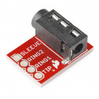
The SparkFun MEMS microphone breakout board is a simple and easy-to-use microphone for a variety of sound-sensing projects. The on-board mic is an ADMP401, which is a low-power, omnidirectional microphone with an analog output. It works for both near and long-range uses and is particularly good for portable applications due to its low power consumption. Possible applications include: smartphones, digital video cameras, and keeping an “ear” on your pets while you’re away.
Read this hook-up guide to get an overview of the breakout board and how to use it, including its technical specifications, how to hook it up to a microcontroller, and an example code to get started!
Questions? Feedback? Want to share an awesome project you built using this sensor? Write a comment at the end of this tutorial!
Suggested Reading
To successfully use the SparkFun MEMS microphone breakout board, you’ll need to be familiar with Arduino microcontrollers, analog (aka ADC) input, and sound waves. For folks new to these topics, check out the following resources to get a feel for the concepts and verbiage used throughout this tutorial.
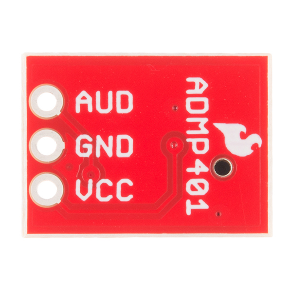
The SparkFun MEMS Microphone breakout board uses the ADMP401 microphone for sound detection. There are three ports for this board: Vcc, the power input (~ 3.3V), GND, or ground, and AUD, the audio signal output. The AUD output is an analog signal.
To power this lil' mic, use a DC voltage between 1.5 and 3.3V with a supply current of about 250 μA.
For technically-minded folks, here are some of the features of the ADMP401:
High Signal-to-Noise Ratio (“SNR”) of 62 dBA
Sensitivity of about -42 dBV
Flat frequency response from 100 Hz to 15 kHz
Low current consumption of <250 μA
Maximum acoustic input of 120 dB
Check out the ADMP401 datasheet for a complete overview of the board.
The SparkFun breakout board includes an amplifier with a gain of 67, which is more than sufficient for the ADMP401 mic. The amplifier’s AUD output will float at one-half Vcc when there is no sound. When held at arms length and talked into, the amplifier will produce a peak-to-peak output of about 200 mV.
Quick Start
If all of this is super familiar, here’s all you need to get started:
Solder wires (or headers) to the three MEMS mic breakout board ports.
Connect the Vcc port to 3.3V (or anything between 1.5 and 3.3V) and the GND port to ground.
Connect the AUD port to an analog (ADC) input on a microcontroller.
Read in the ADMP401 analog signal and measure/record all the sounds! (Also remember it’s a sound signal, so you’ll likely want to use the amplitude of the sound wave rather than the raw voltage output.)
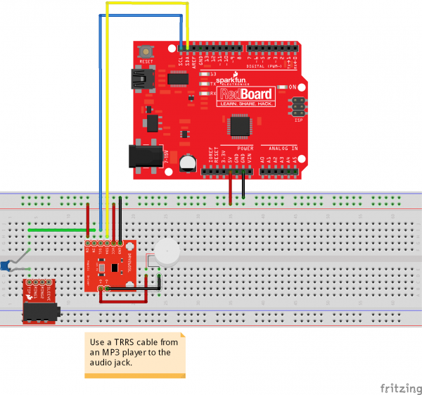
Hardware Hookup
For a more in-depth example, follow along with the following steps:
Solder three wires (or header pins) to the breakout board ports. Recommended to use red for Vcc, black for GND, and yellow (or some other color) for AUD to easily distinguish the board ports.
Connect the Vcc port to the 3.3 V output of a microcontroller (or any power supply between 1.5 and 3.3 V).
Connect the GND port to GND on the microcontroller.
Connect the AUD port to an analog, or ADC, input on the microcontroller.
The next section will cover how to read the Audio signal from the Mic to a microcontroller.
Arduino Software Example
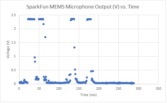
The ADMP401 signal output is a varying voltage. When all is quiet (shhhh), the AUD output will float at one-half the power supply voltage. For example, with a 3.3 V power supply, the AUD output will be about 1.65 V. In the photo below, the yellow marker on the left side of the oscilloscope screen marks the zero axis for the voltage (aka V = 0). The pulse is the AUD output of a finger snap close to the mic.
Converting ADC to Voltage
The microcontroller analog (ADC) input converts our audio signal into an integer. The range of possible ADC values depends on which microcontroller you are using. For an Arduino microcontroller, this range is between 0 and 1023, so the resolution of our ADC measurement is 1024. To convert our analog measurement into a voltage, we use the following equation:
In our case, the ADC Resolution is 1024, and the System Voltage 3.3 V. We’ll need to add this equation in our code to convert our ADC Reading into a voltage.
But Wait, What Are We Actually Measuring??
For many applications that deal with sound (which is a wave), we’re mostly interested in the amplitude of the signal. In general, and for the sake of simplicity, a larger amplitude means a louder sound, and a smaller amplitude means a quieter sound (and the sound wave frequency roughly corresponds to pitch). Knowing the amplitude of our audio signal allows us to build a sound visualizer, a volume unit (“VU”) meter, set a volume threshold trigger, and other cool and useful projects!
To find the audio signal amplitude, take a bunch of measurements in a small time frame (e.g. 50 ms, the lowest frequency a human can hear). Find the minimum and maximum readings in this time frame and subtract the two to get the peak-to-peak amplitude. We can leave it at that, or divide the peak-to-peak amplitude by a factor of two to get the wave amplitude. We can use the ADC integer value, or convert this into voltage as described above.
Sample Code
Below is a simple example sketch to get you started with the MEMS microphone breakout board. You can find the code in the GitHub repo as well. The code, written for an Arduino microcontroller, includes a conversion equation from the ADC Reading to voltage, a function to find the audio signal peak-to-peak amplitude, and a simple VU Meter that outputs to the Arduino Serial Monitor.
Be sure to read the comments in the code to understand how it works and to adapt it to fit your needs.
language:c
/***************************
 * Example Sketch for the SparkFun MEMS Microphone Breakout Board
 * Written by jenfoxbot <jenfoxbot@gmail.com>
 * Code is open-source, beer/coffee-ware license.
 */

// Connect the MEMS AUD output to the Arduino A0 pin
int mic = A0;

// Variables to find the peak-to-peak amplitude of AUD output
const int sampleTime = 50;
int micOut;


void setup() {
  Serial.begin(9600);
}

void loop() {
   int micOutput = findPTPAmp();
   VUMeter(micOutput);
}


// Find the Peak-to-Peak Amplitude Function
int findPTPAmp(){
// Time variables to find the peak-to-peak amplitude
   unsigned long startTime= millis();  // Start of sample window
   unsigned int PTPAmp = 0;

// Signal variables to find the peak-to-peak amplitude
   unsigned int maxAmp = 0;
   unsigned int minAmp = 1023;

// Find the max and min of the mic output within the 50 ms timeframe
   while(millis() - startTime < sampleTime)
   {
      micOut = analogRead(mic);
      if( micOut < 1023) //prevent erroneous readings
      {
        if (micOut > maxAmp)
        {
          maxAmp = micOut; //save only the max reading
        }
        else if (micOut < minAmp)
        {
          minAmp = micOut; //save only the min reading
        }
      }
   }

  PTPAmp = maxAmp - minAmp; // (max amp) - (min amp) = peak-to-peak amplitude
  double micOut_Volts = (PTPAmp * 3.3) / 1023; // Convert ADC into voltage

  //Uncomment this line for help debugging (be sure to also comment out the VUMeter function)
  //Serial.println(PTPAmp);

  //Return the PTP amplitude to use in the soundLevel function.
  // You can also return the micOut_Volts if you prefer to use the voltage level.
  return PTPAmp;
}

// Volume Unit Meter function: map the PTP amplitude to a volume unit between 0 and 10.
int VUMeter(int micAmp){
  int preValue = 0;

  // Map the mic peak-to-peak amplitude to a volume unit between 0 and 10.
   // Amplitude is used instead of voltage to give a larger (and more accurate) range for the map function.
   // This is just one way to do this -- test out different approaches!
  int fill = map(micAmp, 23, 750, 0, 10);

  // Only print the volume unit value if it changes from previous value
  while(fill != preValue)
  {
    Serial.println(fill);
    preValue = fill;
  }
}
Resources and Going Further
If you run into trouble getting, or understanding, an audio signal output from the MEMS mic breakout board, try using a multimeter and/or an oscilloscope to measure the voltage output of the signal in quiet and loud settings. If you’re still stuck, leave a comment, and we’ll help you troubleshoot.
After you’ve read in the MEMS microphone and have a good handle on the signal output, you’re ready to start using it for practical microphone applications! Here are a few ideas to get you started:
The CY7C65213 USB to UART serial breakout is designed to provide users with a means to access all available I/O pins on the CY7C65213 part and to provide a 6-pin UART header that is compatible with other SparkFun breakout boards. This tutorial will explain the use of the board in greater detail.
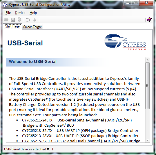
We will explain the layout of the board, proper usage of the jumpers on the board to change the I/O voltage, and use of the Cypress configuration application to change default settings on the board to meet your own needs.
As we work through the Hookup Guide, you may find it useful to have the CY7C65213 USB to UART Datasheet on hand.
At a minimum, you should be familiar with asynchronous serial communication, as that is the central function of this chip. You should also have some idea of what we mean when we talk about different logic levels, or voltages, so you know when to change the logic level for your board.
Hardware Overview
Here we will go over the various parts of the board, providing an explanation for each and detailed usage instructions.
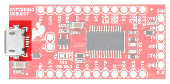
Micro-B USB port—This is where the cable from the host device connects to this PC. Power can be supplied through this connector to this board, as well as to the circuit it is attached to.
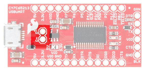
USB signal lines—These two pads break out the D+ and D- signal lines for user access. These signals can then be brought out to a different connector if desired.
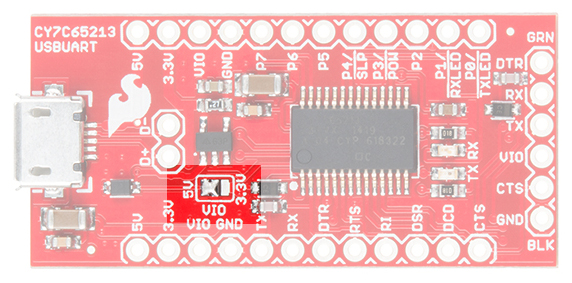
VIO selection jumper—This jumper is used to select the voltage that appears at the VIO pin on the 6-pin serial header. The left two pads can be closed to supply 5V directly from the USB power line, or the right two pads can be closed to supply 3.3V via an onboard 500mA regulator. If the attached board is going to provide a voltage reference for an alternative voltage (say, 2.5V or 1.8V), remove all solder from this jumper.
5V pin—Supplies 5V directly from the USB power.
3.3V pin—Supplies 3.3V from a 500mA 3.3V regulator connected to the USB power line.
VIO pin—Tied to the VIO pin on the 6-pin serial header, this will either be connected to 5V or 3.3V, depending on the VIO selection jumper, or it will reflect the voltage present on VIO if the downstream board is providing a reference voltage for this board.
Variable purpose I/O pins—The purpose of these pins will be discussed later, but in normal operation they are seldom, if ever, used.
DTE port pins—These pins provide the same functionality as the similarly named pins on an RS-232 port, albeit at VIO voltage rather than the bipolar voltage of true RS-232. DTR and CTS are the most commonly used. We’ll discuss the role of these pins later.
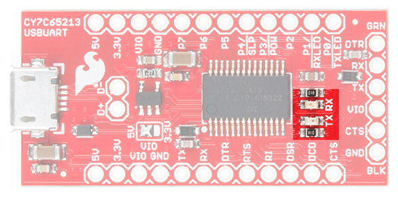
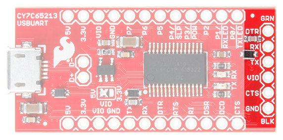
TX and RX LEDs—These LEDs light up when data is being transferred over the serial channel. The TX LED lights up when data is being sent from the host to the attached board, and the RX LED lights up when data is being sent back from the attached board to the host.
6-pin serial header—A longtime standard on SparkFun (and other) boards, this header contains the minimum necessary signals for communicating with a downstream board. It can be used to program Arduino Pro and Pro Mini boards, among others.
Low-voltage select jumper—On the underside of the board, you’ll find a jumper that should only be set in cases where VIO is 2V or less. Since there is no onboard reference for that voltage, this will be in cases where the downstream board is providing the reference voltage.
Programming an Arduino Pro or Pro Mini
The CY7C65213 chip can be used to program an Arduino Pro or Pro Mini, just like SparkFun’s other FTDI-based USB to UART chips. As a basic example for getting started with this board, we will be demonstrating this hardware connection.
Having a hard time seeing the circuit? Click on the wiring diagram for a closer look.
Note that, unlike the other boards, you’ll need to buy some kind of header to interface to the Arduino board, as no header comes pre-soldered to the CY7C65213 breakout. This affords you the option to choose the connector that best suits your purpose or to solder wires directly between the two boards.
Don’t Forget! Double check that the VIO Selection Jumper is set to the appropriate voltage level for the board you are connecting to (5V/3.3V). If you are connecting to a board with a different reference voltage, remove all solder from this jumper before powering up your circuit.
Once the board is connected and the driver is installed (which should happen automatically on all major operating systems), no other changes are needed for the board to be used as a programming connection. Simply select the COM or TTY port in the Arduino software and proceed as normal.
Using the Board at Voltages Below 2V
Hardware Changes on the PCB
To enable support for voltages below 2V, you must first disconnect the board from your PC and adjust the jumpers on the PCB.
Shown below is the VIO selection jumper. You must remove all solder from this jumper before proceeding. We suggest using some solder wick to achieve this.
Now, you must close the low-voltage jumper on the bottom side of the PCB with solder.
We’ve created a special footprint just for solder jumpers to make it as easy as possible to close the jumper. Simply heat both pads and then apply the solder to the pads; a bridge should form naturally. Do not apply too much solder.
Software Settings on the PC
Cypress offer a downloadable configuration utility for this chip. Sadly, it is currently offered only for the Microsoft Windows platform. You’ll need to download and install this utility before you can use the chip for voltages below 2V.
When you first open the utility, this is what you will see. In the lower left, you should see the utility displaying the number of Cypress USB UART boards only (other manufacturers' chips, such as FTDI, Arduino or Prolific will not be reflected in this number). Assuming your chip has shown up here, go ahead and click on the Select Target tab at the top.
This is the Select Target tab. The dropdown will list available Cypress USB UART boards, and information (probably more than you want or need) will appear in the window below it. Click the Connect button to proceed, making sure that there are no open terminal windows (such as the Arduino IDE serial port monitor) using this board at the moment first.
A new tab will appear and become automatically selected. In the lower left corner of this new tab, you can see a checkbox labeled VCCIO voltage is less than 2V. Click this checkbox, then click the Program button at the bottom of the page. The chip is now configured for use at less than 2V.
Resources and Going Further
For more on the Cypress CY7C65213 USB UART chip, please check out the links below:
USB UART SDK from Cypress— If you are an experienced system-level software developer, it’s possible to use the Cypress drivers to achieve additional goals with the 7C65213 chip. It has onboard I/O, for instance, which can be used for out-of-band communications with the target PCB.
The TMP102 is an easy-to-use digital temperature sensor from Texas Instruments. While some temperature sensors use an analog voltage to represent the temperature, the TMP102 uses the I2C bus of the Arduino to communicate the temperature.
3.3V sensor - use inline logic level converters or 10 kΩ resistors to limit 5V signals
Supports up to four TMP102 sensors on the I2C bus at a time
Pull-up Resistors
This breakout board has built-in 4.7 kΩ pull up resistors for I2C communications. If you’re hooking up multiple I2C devices on the same bus, you may want to disable/enable the pull-up resistors for one or more boards. On the TMP102, the pull-ups are enabled by default. To disable them, simply use a hobby knife to cut the traces connecting the left and right pads of the jumper labeled I2C PU on the back of the board. This will disconnect the resistors from VCC and from the I2C bus.
Hardware Connections
Connecting the TMP102 to an Arduino
Wiring the TMP102 is very easy! We recommend soldering six male headers to the breakout board. You can also solder wires to fit your application’s needs.
Power
This board runs from 1.4V to 3.6V. Be sure to power the board from the 3.3V pin! I2C uses an open drain signaling, so there is no need to use level shifting; the 3.3V signal will work to communicate with the Arduino and will not exceed the maximum voltage rating of the pins on the TMP102.
Connections to the Arduino
The TMP102 breakout board has six pins, however we’ll only be using five of the pins in today’s example. We’ll be connecting VCC and GND to the normal power pins, two data lines for I2C communication, and one digital pin to see if there is an alert. If you’re using a newer board that has SDA and SCL broken out, you can connect the SDA and SCL pins directly to those pins. If you’re using an older board, SDA and SCL are pins A4 and A5 respectively.
VCC → 3.3V
GND → GND
SDA → SDA/A4
SCL → SCL/A5
ALT → A3
This would looks something like this:
The only pin that we aren’t using is ADD0, this pin is used to change the address of the TMP102. If you’re using multiple TMP102s or another device that uses that address, you’ll want to use this pin to change the address. The default address is 0x48. You can change the address by connecting an external jumper wire to the following pins:
VCC → 0x49
SDA → 0x4A
SCL → 0x4B
TMP102 Library and Example Code
Note:This example assumes you are using the latest version of the Arduino IDE on your desktop. If this is your first time using Arduino, please review ou tutorial on installing the Arduino IDE. If you have not previously installed an Arduino library, please check out our installation guide.
To get started immediately, use the example code and library files below.
language:c
/******************************************************************************
TMP102_example.ino
Example for the TMP102 I2C Temperature Sensor
Alex Wende @ SparkFun Electronics
April 29th 2016
~

This sketch configures the TMP102 temperature sensor and prints the
temperature and alert state (both from the physical pin, as well as by
reading from the configuration register.

Resources:
Wire.h (included with Arduino IDE)
SparkFunTMP102.h

Development environment specifics:
Arduino 1.0+
Hardware Version 13

This code is beerware; if you see me (or any other SparkFun employee) at
the local, and you've found our code helpful, please buy us a round!

Distributed as-is; no warranty is given.
******************************************************************************/

#include <Wire.h> // Used to establied serial communication on the I2C bus
#include "SparkFunTMP102.h" // Used to send and recieve specific information from our sensor

// Connections
// VCC = 3.3V
// GND = GND
// SDA = A4
// SCL = A5
const int ALERT_PIN = A3;

TMP102 sensor0(0x48); // Initialize sensor at I2C address 0x48
// Sensor address can be changed with an external jumper to:
// ADD0 - Address
//  VCC - 0x49
//  SDA - 0x4A
//  SCL - 0x4B

void setup() {
  Serial.begin(9600); // Start serial communication at 9600 baud
  pinMode(ALERT_PIN,INPUT);  // Declare alertPin as an input
  sensor0.begin();  // Join I2C bus

  // Initialize sensor0 settings
  // These settings are saved in the sensor, even if it loses power

  // set the number of consecutive faults before triggering alarm.
  // 0-3: 0:1 fault, 1:2 faults, 2:4 faults, 3:6 faults.
  sensor0.setFault(0);  // Trigger alarm immediately

  // set the polarity of the Alarm. (0:Active LOW, 1:Active HIGH).
  sensor0.setAlertPolarity(1); // Active HIGH

  // set the sensor in Comparator Mode (0) or Interrupt Mode (1).
  sensor0.setAlertMode(0); // Comparator Mode.

  // set the Conversion Rate (how quickly the sensor gets a new reading)
  //0-3: 0:0.25Hz, 1:1Hz, 2:4Hz, 3:8Hz
  sensor0.setConversionRate(2);

  //set Extended Mode.
  //0:12-bit Temperature(-55C to +128C) 1:13-bit Temperature(-55C to +150C)
  sensor0.setExtendedMode(0);

  //set T_HIGH, the upper limit to trigger the alert on
  sensor0.setHighTempF(85.0);  // set T_HIGH in F
  //sensor0.setHighTempC(29.4); // set T_HIGH in C

  //set T_LOW, the lower limit to shut turn off the alert
  sensor0.setLowTempF(84.0);  // set T_LOW in F
  //sensor0.setLowTempC(26.67); // set T_LOW in C
}

void loop()
{
  float temperature;
  boolean alertPinState, alertRegisterState;

  // Turn sensor on to start temperature measurement.
  // Current consumtion typically ~10uA.
  sensor0.wakeup();

  // read temperature data
  temperature = sensor0.readTempF();
  //temperature = sensor0.readTempC();

  // Check for Alert
  alertPinState = digitalRead(ALERT_PIN); // read the Alert from pin
  alertRegisterState = sensor0.alert();   // read the Alert from register

  // Place sensor in sleep mode to save power.
  // Current consumtion typically <0.5uA.
  sensor0.sleep();

  // Print temperature and alarm state
  Serial.print("Temperature: ");
  Serial.print(temperature);

  Serial.print("\tAlert Pin: ");
  Serial.print(alertPinState);

  Serial.print("\tAlert Register: ");
  Serial.println(alertRegisterState);

  delay(1000);  // Wait 1000ms
}
Once the library is installed, open Arduino, and expand the examples menu. You should see the TMP102 example.
TMP102 Functions
Main functions
These are functions used to read settings and temperatures from the sensor.
TMP102::readTempC() - Returns the current temperature in Celsius.
TMP102::readTempF() - Returns the current temperature in Fahrenheit.
TMP102::readLowTempC(float temperature) - Reads T_LOW register in Celsius.
TMP102::readHighTempC(float temperature) - Reads T_HIGH register in Celsius.
TMP102::readLowTempF(float temperature) - Reads T_LOW register in Fahrenheit.
TMP102::readHighTempF(float temperature) - Reads T_HIGH register in Fahrenheit.
TMP102::sleep() - Put TMP102 in low power mode (<0.5 uA).
TMP102::wakeup() - Return to normal power mode (~10 uA). When the sensor powers up, it is automatically running in normal power mode, and only needs to be used after TMP102::sleep() is used.
TMP102::alert() - Returns the state of the Alert register. The state of the register is the same as the ALT pin.
Nonvolatile Functions
These are settings that are saved in the sensor, even after power is removed.
TMP102::setLowTempC(float temperature) - Sets T_LOW (in Celsius) alert threshold.
TMP102::setHighTempC(float temperature) - Sets T_HIGH (in Celsius) alert threshold.
TMP102::setLowTempF(float temperature) - Sets T_LOW (in Fahrenheit) alert threshold.
TMP102::setHighTempF(float temperature) - Sets T_HIGH (in Fahrenheit) alert threshold.
TMP102::setConversionRate(byte rate) - Sets the temperature reading conversion rate. 0: 0.25Hz, 1: 1Hz, 2: 4Hz (default), 3: 8Hz.
TMP102::setExtendedMode(byte mode) - Enable or disable extended mode. 0: disabled (-55C to +128C), 1: enabled (-55C to +150C).
TMP102::setAlertPolarity(bool polarity) - Sets the polarity of the alert. 0: active LOW, 1: active HIGH
TMP102::setFault(byte faultSetting) - Sets the number of consecutive faults before triggering alert. 0: 1 fault, 1: 2 faults, 2: 4 faults, 3: 6 faults.
TMP102::setAlertMode(bool mode) - Sets the type of alert. 0: Comparator Mode (Active from when temperature > T_HIGH until temperature < T_LOW), 1: Thermostat mode (Active from when temperature > T_HIGH until any read operation occurs.
Resources and Going Further
For more information about the TMP102 Breakout, check out the links below.
The Serial Basic is an easy to use USB to Serial adapter based on the CH340G IC from WCH. It works with 5V and 3.3V systems and should auto install on most operating systems without the need for additional drivers. It’s a great lower cost option to the extremely popular FTDI Basic.
The Serial Basic uses the CH340G IC to quickly and easily convert serial signals to USB. It works great with all of our products including the Arduino Pro Mini, our GPS modules, cellular modules, and many other devices that uses serial communication.
Suggested Reading
This is an easy board to get started with, but, if you are not sure how serial works or have not used a terminal program before, you may want to checkout the following tutorials.
The pinout of the Serial Basic mimics the common DTR/RX/TX/VCC/CTS/GND pinout found on hundreds of FTDI-to-USB derivatives.
Pin Label
Input/Output
Description
DTR
Output
Data Terminal Ready, Active Low
RXI
Input
Serial Receive
TXO
Output
Serial Transmit
VCC
Supply Output
Power supply 3.3V or 5V
CTS
Input
Clear To Send, Active Low
GND
Supply Output
Ground (0V) supply
Alignment Markers
These GRN and BLK indicators are there to help you align the board properly with products that use this same pinout.
The Serial Basic mates seamlessly with products that use the standard serial connection. If you see a board with the BLK and GRN labels, then you know it will be compatible with the Serial Basic.
Where did GRN and BLK come from? Way back in 2008, when we created the Arduino Pro Mini, we needed to have a pinout to allow serial bootloading. At the time, the best USB to TTL Serial device was the FT232 Cable. Its unpolarized connector could be flipped either way so we added the words GRN and BLK to the PCB to let folks know how to line up the colored wires. The practice stuck! Now, many boards use this standard.
The cable with colored wires
Voltage Selection Jumper
There is a jumper on the rear of the board that controls the output voltage on the VCC pin. By default, the board outputs 3.3V and has 3.3V signals. Changing this jumper to 5V will cause the board to output 5V on the VCC pin with 5V signals.
Jumper is default to 3.3V VCC and I/O
When the jumper is set to 3.3V, the board uses an onboard 3.3V regulator capable of sourcing 600mA. If you attempt to pull more than 600mA, the regulator will go into short-circuit shutdown where it will only output 150mA.
When the jumper is set to 5V, the board will source as much power as your USB port will provide.
LEDs
There are two LEDs on the board connected to TX (Green) and RX (Yellow). This is a quick and handy way to see the serial traffic.
Hardware Test
To connect the board to a computer, you will need a standard A to micro-B USB cable. Plug the micro-B USB cable into a USB port on your computer and the other end into the Serial Basic. Your computer should automatically install the necessary drivers and create a COM port on your computer. If you are prompted for drivers, please see the Installing Drivers section.
The quickest and easiest way to make sure everything is working is to do a TX/RX loop-back. To do this, insert a jumper wire between TX and RX. Anything that is transmitted from the TX pin will be echoed back to the RX pin.
Open your favorite terminal program. Select the COM port that the Serial Basic is assigned to, and connect. When you type a character, you should see each character you type echoed back in the terminal.
Success!
Which COM Port Do I Need?
Most programs will show you a description of the USB device that created the port. Look for the port associated with CH340.
If you’re using the Arduino IDE, figuring out which COM port is the one you want is more difficult. Here’s the quick way to figure it out: attach the Serial Basic to your computer, and check which COM ports are listed. In the image below, we have two ports. Now close the Tool menu by clicking on the main Arduino IDE window.
Which COM port should I select?
Unplug the Serial Basic, and re-open the Tools->Ports submenu. You will see one of the serial ports is missing. That’s the one you want! Plug your Serial Basic back in, and use that COM port.
Note: You need to close and re-open the tools menu before Arduino will refresh the port list. If you have the tool menu open simply click on the main window, then click back on Tools->Port.
Drivers If You Need Them
The Serial Basic has been tested on Windows 7, Windows 8.x, Windows 10, Linux Mint, and OSX Yosemite, El Capitan, and Sierra. These operating systems have the CDC drivers pre-installed, which means you shouldn’t need to install any extra software. However, there are a wide range of operating systems out there, so, if you run into driver problems, you can get drivers here.
The CH340G is made by WCH. You can find the latest version of their drivers here, but most of their pages are in Mandarin.
Resources and Going Further
Once you’ve got serial communication working, you’re ready to start playing with serial projects. Consider connecting to a GPS module like the LS20031 (one of my favorites) and watching the serial strings roll by. Or, you can use the Serial Basic to program and debug devices like the Arduino Pro Mini. There are tons of devices that use serial to communicate, so go explore!
How to use the SparkFun FTDI based boards to program an Arduino and access another serial device over the hardware serial port, without unplugging anything!
This SparkFun Tinker Kit Experiment Guide is your map for navigating the waters of beginning embedded electronics, robotics and citizen science using the SparkFun RedBoard while sticking to a strict budget. This guide contains all the information you will need to explore the 11 circuits of the SparkFun Tinker Kit. At the center of this guide is one core philosophy – that anyone can (and should) play around with cutting-edge electronics in a fun and playful way while not breaking the bank.
When you’re done with this guide, you’ll have the know-how to start creating your own projects and experiments. From building robots and game controllers to data logging, the world will be your oyster. Now enough talking – let’s start tinkering!
Here are all of the parts in the SparkFun Tinker Kit:
SparkFun RedBoard– Our tried and true version of the Arduino UNO.
Breadboard– Excellent for making circuits and connections off the Arduino.
SparkFun Mini Screwdriver– To help you screw your RedBoard onto the holder.
Hobby Gearmotor Set– A set of hobby level motors with gearboxes set to 120 RPM.
Small Servo– Here is a simple, low-cost, high-quality servo for all your mechatronic needs.
TMP36 Temp Sensor– A sensor for detecting temperature changes.
USB A to B Cable– This 6-foot cable provides you with a USB-A connector at the host end and standard B connector at the device end.
Male-to-Male Jumper Wires– These are high-quality wires that allow you to connect the female headers on the Arduino to the components and breadboard.
Photocell– A sensor to detect ambient light. Perfect for detecting when a drawer is opened or when nighttime approaches.
Tri-Color LED– Because everyone loves a blinky.
Red, Blue, Yellow and Green LEDs– Light-Emitting Diodes make great general indicators.
Red, Blue, Yellow and Green Tactile Buttons– Go crazy with different colored buttons.
10K Trimpot– Also known as a variable resistor, this is a device commonly used to control volume and contrast, and makes a great general user control input.
330 Ohm Resistors– Great current-limiting resistors for LEDs, and strong pull-up resistors.
10K Ohm Resistors– These make excellent pull-ups, pull-downs and current limiters.
SN754410 H-Bridge IC– This nifty little Integrated Circuit (IC) is perfect for controlling the speed and direction of up to two separate motors.
4xAA Battery Holder– Used to power the RedBoard without being connected to your computer. Sorry! Batteries not included.
Experiment List
The following is a list of the experiments you will complete using this Tinker Kit Experiment Guide. Alternatively, you can navigate around using the buttons on the right.
Before continuing with this guide, we recommend you be somewhat familiar with the concepts in the following tutorials:
Voltage, Current, Resistance, and Ohm’s Law - The most basic concepts in electronics and electrical engineering. Get very familiar with these concepts as they will be used throughout your electronics adventure.
What is a Circuit? - In this guide, we will be building a variety of circuits. Understanding what that means is vital to understanding the Inventor’s Kit.
How to Use a Breadboard– First time working with a breadboard? Please check out this tutorial! It will help you understand why the breadboard is great for prototyping and how to use one.
Open Source!
At SparkFun, our engineers and educators have been improving this kit and coming up with new experiments for a long time. We would like to give attribution to Oomlout, since we originally started working off the Arduino Kit material many years ago. Both the Oomlout and SparkFun versions are licensed under the Creative Commons Attribution Share-Alike 3.0 Unported License.
To view a copy of this license visit this link, or write: Creative Commons, 171 Second Street, Suite 300, San Francisco, CA 94105, USA.
What is the RedBoard?
At SparkFun we use many Arduinos, and we’re always looking for the simplest, most stable one. Each board is a bit different, and no one board has everything we want, so we decided to make our own version that combines all our favorite features. The SparkFun RedBoard combines the simplicity of the UNO’s Optiboot bootloader (which is used in the Pro series), the stability of the FTDI (which we all missed after the Duemilanove was discontinued) and the R3 shield compatibility of the latest Arduino UNO R3.
The RedBoard can be programmed over a USB Mini-B cable using the Arduino IDE: Just plug in the board, select “Arduino UNO” from the board menu, and you’re ready to upload code. RedBoard has all of the hardware peripherals you know and love: 14 Digital I/O pins with 6 PWM pins, 6 Analog Inputs, UART, SPI and external interrupts. We’ve also broken out the SDA, SCL and IOREF pins that showed up on the UNO R3, so the RedBoard will be compatible with future shields. This version adds an SMD ISP header for use with shields.
You can power the RedBoard over USB or through the barrel jack. The on-board power regulator can handle anything from 7 to 15VDC. Check out the related items below for a compatible wall-wart power supply.
Introduction to the Arduino IDE
Before you plug the RedBoard into your computer, you’ll need to install Arduino.
Installing Arduino
To begin, head over to Arduino’s download page and grab the most recent, stable release of Arduino. Make sure you grab the version that matches your operating system.
The installation procedure is fairly straightforward, but it varies by OS. Here are some tips to help you along. We’ve also written a separate Installing Arduino tutorial if you get really stuck.
Windows Install Tips
The Windows version of Arduino is offered in two options: an installer or a zip file. The installer is the easier of the two options; just download that, and run the executable file to begin installation. If you’re prompted to install a driver during installation, select “Don’t Install” (the RedBoard doesn’t use the same drivers). Don’t forget which directory it installs to (defaults to “Program Files/Arduino”).
Windows install steps. Click the image for a closer look.
If, instead, you choose to download the zip file version of Arduino, you’ll need to extract the files yourself. Don’t forget which folder you extract the files into! We’ll need to reference that directory when we install drivers.
Mac Install Tips
The Mac download of Arduino is only offered in a zip file version. After the download is finished, simply double-click the .zip file to unzip it.
Following that, you’ll need to copy the Arduino application into your applications folder to complete installation.
Linux Install Tips
As Linux users are no doubt aware, there are many flavors of Linux out there, each with unique installation routines. Check out the Linux section of the Installing Arduino tutorial for some helpful links for an assortment of Linux distributions.
For Ubuntu and Debian users, installing Arduino should be as easy as running a little “apt-get” magic, with a command like:
And other Linux distros aren’t too dissimilar from that.
With Arduino downloaded and installed, the next step is to plug the RedBoard in and install some drivers! Pretty soon you’ll be blinking LEDs, reading buttons, and doing some physical computing!
Installing FTDI Drivers
Once you have downloaded and installed Arduino, it’s time to connect the RedBoard to your computer! Before you can use the board, though, you’ll need to install drivers.
Windows Driver Installation
After initially plugging your RedBoard in, your computer will try to search for a compatible driver. It may actually succeed! The FTDI drivers are pretty common, so Windows Update may know a little something about them. If the drivers do automatically install, you should see a little bubble notification saying so:
If your computer failed to find drivers, we’ll have to install them manually. Check out our Windows FTDI Driver install guide for driver installation instructions.
Mac Driver Installation
If you’re lucky, the FTDI drivers should automatically install on Mac OS X; otherwise you’ll have to manually install the drivers. Check out the Mac FTDI Driver install guide for help installing the drivers.
In short, the process involves heading over to the FTDI driver website, and downloading the most up-to-date VCP drivers. Then you’ll simply run the “FTDIUSBSerialDriver_v2_2_18.dmg” file you downloaded, and follow the installation prompts.
Linux Driver Installation
Linux is actually pretty good about automatically installing the drivers. If you have any trouble, check out our Linux FTDI Driver install guide.
Now it’s time to breathe easy! You’ll only have to run through this driver installation process once, the first time you connect the board to your computer. Now it’s time to upload a sketch!
Experiment 1: Blink an LED
Introduction
LEDs are small, powerful lights that are used in many different applications. To start off, we will work on blinking an LED, the “Hello, World!” of microcontrollers. That’s right – it’s as simple as turning a light on and off. It might not seem like much, but establishing this important baseline will give you a solid foundation as we work toward more complex experiments.
Parts Needed
You will need the following parts:
1x Breadboard
1x SparkFun RedBoard
1x LED
1x 330Ω Resistor
3x Jumper Wires
Didn’t Get the Tinker Kit?
If you are conducting this experiment and didn’t get the Tinker Kit, we suggest using these parts:
A Light-Emitting Diode (LED) will only let current through it in one direction. Think of an LED as a one-way street. When current flows through the LED, it lights up! When you are looking at the LED, you will notice that its legs are different lengths. The long leg, the “anode,” is where current enters the LED. This pin should always be connected to the current source. The shorter leg, the “cathode,” is the current’s exit. The short leg should always be connected to a pathway to ground.
LEDs are finicky when it comes to how much current you apply to them. Too much current can lead to a burnt-out LED. To restrict the amount of current that passes through the LED, we use a resistor in line with the power source and the LED’s long leg; this is called a current-limiting resistor. With the RedBoard, you should use a 330 Ohm resistor. We have included a baggy of them in the kit just for this reason!
Hardware Hookup
Ready to start hooking everything up? Check out the wiring diagram and hookup table below to see how everything is connected.
Polarized Components
Pay special attention to the component’s markings indicating how to place it on the breadboard. Polarized components can only be connected to a circuit in one direction.
Please note: Pay close attention to the LED. The negative side of the LED is the short leg, marked with a flat edge.
Components like resistors need to have their legs bent into 90° angles in order to correctly fit the breadboard sockets. You can also cut the legs shorter to make them easier to work with on the breadboard.
Wiring Diagram for the Experiment
Having a hard time seeing the circuit? Click on the wiring diagram for a closer look.
Open Your First Sketch
Open the Arduino IDE software on your computer. Coding in the Arduino language will control your circuit. Open the code for Circuit 1 by accessing the “Tinker Kit Guide Code” you downloaded and placed into your “Examples” folder earlier.
To open the code go to: File > Examples > Tinker Kit Guide Code > Circuit_01
You can also copy and paste the following code into the Arduino IDE. Hit upload, and see what happens!
language:cpp
/*
SparkFun Tinker Kit
Example sketch 01

BLINKING AN LED

Turn an LED on for one second, off for one second,
and repeat forever.

This sketch was written by SparkFun Electronics,
with lots of help from the Arduino community.
This code is completely free for any use.
Visit http://learn.sparkfun.com/products/2 for SIK information.
Visit http://www.arduino.cc to learn about Arduino.
*/


//The setup function runs once upon your Arduino being powered or once upload is          //complete.

void setup()
{
  //set pin 13 to OUTPUT
  pinMode(13, OUTPUT);
}

//The loop function runs from the top down and repeats itself until you upload new        //code or power down your Arduino
void loop()
{
  //Turn pin 13 HIGH (ON).
  digitalWrite(13, HIGH);

  //wait 1000 milliseconds (1 second)
  delay(1000);

  //Turn pin 13, LOW (OFF)
  digitalWrite(13, LOW);

  //wait 1000 milliseconds
  delay(1000);
}
Code to Note
pinMode(13, OUTPUT);
Before you can use one of the RedBoards' pins, you need to tell the board whether it is an INPUT or OUTPUT. We use a built-in “function” called pinMode() to do this.
digitalWrite(13, HIGH);
When you’re using a pin as an OUTPUT, you can command it to be HIGH (output 5 volts), or LOW (output 0 volts).
What You Should See
You should see your LED blink on and off. If it doesn’t, make sure you have assembled the circuit correctly and verified and uploaded the code to your board, or see the Troubleshooting section.
Troubleshooting
Program Not Uploading
This happens sometimes; the most likely cause is a confused serial port. You can change this in Tools > Serial Port >
Also, if you get a Timeout error or the IDE could not find your 101 board, try pressing the Master Reset button on the 101, wait around 10 seconds and try re-uploading your sketch.
Still No Success
A broken circuit is no fun. Send us an email, and we will get back to you as soon as we can: techsupport@sparkfun.com
Experiment 2: Reading a Potentiometer
Introduction
In this circuit you will work with a potentiometer. You will learn how to use a potentiometer to control the timing of a blinking LED by reading a sensor and storing it as a variable, then using it as your delay timing.
Parts Needed
You will need the following parts:
1x Breadboard
1x SparkFun RedBoard
1x LED
1x 330Ω Resistor
7x Jumper Wires
1x Potentiometer
Didn’t Get the Tinker Kit?
If you are conducting this experiment and didn’t get the Tinker Kit, we suggest using these parts:
A potentiometer is a resistance-based analog sensor that changes its internal resistance based on the rotation of its knob. The potentiometer has an internal voltage divider enabling you to read the change in voltage on the center pin with a microcontroller (the RedBoard). To hook up the potentiometer, attach the two outside pins to a supply voltage (5V in this circuit) and ground. It doesn’t matter which is connected where, as long as one is connected to power, and the other to ground. The center pin is then connected to an analog input pin so the RedBoard can measure the change in voltage. When you twist the knob, the sensor reading will change!
Note: The potentiometer included in the kit has three marks on it that will help you figure out which breadboard rows the pins are plugged into.
Hardware Hookup
Ready to start hooking everything up? Check out the wiring diagram and hookup table below to see how everything is connected.
Polarized Components
Pay special attention to the component’s markings indicating how to place it on the breadboard. Polarized components can only be connected to a circuit in one direction.
Wiring Diagram for the Experiment
Having a hard time seeing the circuit? Click on the wiring diagram for a closer look.
Open the Sketch
Open the Arduino IDE software on your computer. Coding in the Arduino language will control your circuit. Open the code for Circuit 2 by accessing the “Tinker Kit Guide Code” you downloaded and placed into your “Examples” folder earlier.
To open the code go to: File > Examples > Tinker Kit Guide Code > Circuit_02
Copy and paste the following code into the Arduino IDE. Hit upload, and see what happens!
language:cpp
/* SparkFun Tinker Kit
Example sketch 02

POTENTIOMETER

  Measure the position of a potentiometer and use it to
  control the blink rate of an LED. Turn the knob to make
  it blink faster or slower!

This sketch was written by SparkFun Electronics,
with lots of help from the Arduino community.
This code is completely free for any use.
Visit http://learn.sparkfun.com/products/2 for SIK information.
Visit http://www.arduino.cc to learn about Arduino.
*/


//Create global variables (variables that can be used anywhere in our sketch)

// Here we're creating a variable called "sensorPin" of type "int"
// and initializing it to have the value "0," which is the analog input pin the pot is     //conected to.
int sensorPin = 0;

// Variable for storing the pin number that the LED is connected to
int ledPin = 13;

// this function runs once when the sketch starts up
void setup()
{
  //set ledPin (13) as an OUTPUT
  pinMode(ledPin, OUTPUT);
}

// this function runs repeatedly after setup() finishes
void loop()
{

  //create a local variable (variable that can only be used inside of loop() to store       //a sensor value called sensorValue
  int sensorValue;

  //use the analogRead() function to read sensorPin and store the value in sensorValue
  sensorValue = analogRead(sensorPin);

  // Turn the LED on
  digitalWrite(ledPin, HIGH);


  delay(sensorValue);

  // Turn the LED off
  digitalWrite(ledPin, LOW);

 //delay for the value of sensorValue
  delay(sensorValue);

  //loop back to the top
}
Code to Note
int sensorValue;
A “variable” is a placeholder for values that may change in your code. You must introduce, or “declare,” variables before you use them; here you are declaring a variable called sensorValue, of type “int” (integer). Don’t forget that variable names are case sensitive!
sensorValue = analogRead(sensorPin);
Use the analogRead() function to read the value on an analog pin. analogRead() takes one parameter, the analog pin you want to use (“sensorPin”), and returns a number (“sensorValue”) between 0 (0 volts) and 1023 (3.3 volts).
delay(sensorValue);
Microcontrollers are very fast, capable of running thousands of lines of code each second. To slow it down so that we can see what it’s doing, we’ll often insert delays into the code. delay() counts in milliseconds; there are 1,000 ms in one second.
What You Should See
You should see the LED blink faster or slower in accordance with your potentiometer. If it isn’t working, make sure you have assembled the circuit correctly and verified and uploaded the code to your board, or see the Troubleshooting section.
Troubleshooting
Sporadically Working
This is most likely due to a slightly dodgy connection with the potentiometer’s pins. This can usually be conquered by holding the potentiometer down or moving the potentiometer circuit somewhere else on your breadboard.
Not Working
Make sure you haven’t accidentally connected the wiper (center pin), the resistive element in the potentiometer, to digital pin 0 rather than analog pin 0 (the row of pins beneath the power pins).
LED Not Lighting Up
LEDs will only work in one direction. Double check your connections.
Experiment 3: Driving an RGB LED
Introduction
You know what’s even more fun than a blinking LED? Changing colors with one LED. In this circuit, you’ll learn how to use an RGB LED to create unique color combinations. Depending on how bright each diode is, nearly any color is possible!
Parts Needed
You will need the following parts:
1x Breadboard
1x SparkFun RedBoard
1x Common Cathode RGB LED
3x 330Ω Resistors
6x Jumper Wires
Didn’t Get the Tinker Kit?
If you are conducting this experiment and didn’t get the Tinker Kit, we suggest using these parts:
The Red Green Blue (RGB) LED is 3 LEDs in one. The RGB has four pins with each of the three shorter pins controlling an individual color: red, green or blue. The longer pin of the RGB is the common ground pin. You can create a custom colored LED by turning different colors on and off to combine them. For example, if you turn on the red pin and green pin, the RGB will light up as yellow.
But which pin is which color? Pick up the RGB so that the longest pin (common ground) is aligned to the left as shown in the graphic below. The pins are Red, Ground, Green and Blue – starting from the far left.
Note: When wiring the RGB, each colored pin still needs a current-limiting resistor in line with the RedBoard pin that you plan to use to control it, as with any standard LED.
Hardware Hookup
Ready to start hooking everything up? Check out the wiring diagram and hookup table below to see how everything is connected.
Polarized Components
Pay special attention to the component’s markings indicating how to place it on the breadboard. Polarized components can only be connected to a circuit in one direction. Polarized components are highlighted with a yellow warning triangle in the table below.
Wiring Diagram for the Experiment
Having a hard time seeing the circuit? Click on the wiring diagram for a closer look.
Open the Sketch
Open the Arduino IDE software on your computer. Coding in the Arduino language will control your circuit. Open the code for Circuit 3 by accessing the “Tinker Kit Guide Code” you downloaded and placed into your “Examples” folder earlier.
To open the code go to: File > Examples >Tinker Kit Guide Code > Circuit_03
You can also copy and paste the following code into the Arduino IDE. Hit upload, and see what happens!
language:cpp
/*
SparkFun Tinker Kit
Example sketch 03

RGB LED

Make an RGB LED display a rainbow of colors!


This sketch was written by SparkFun Electronics,
with lots of help from the Arduino community.
Visit http://learn.sparkfun.com/products/2 for SIK information.
Visit http://www.arduino.cc to learn about Arduino.
*/

//create variables for pin numbers. We are making them constants here, because they       //never change.
const int RED_PIN = 5;
const int GREEN_PIN = 6;
const int BLUE_PIN = 9;

// How fast we plan to cycle through colors in milliseconds
int DISPLAY_TIME = 10;


void setup()
{
//set the three pin variables as outputs
pinMode(RED_PIN, OUTPUT);
pinMode(GREEN_PIN, OUTPUT);
pinMode(BLUE_PIN, OUTPUT);
}


void loop()
{
// We've written a custom function called mainColors() that steps
// through all eight of these colors. We're only "calling" the
// function here (telling it to run). The actual function code
// is further down in the sketch.
mainColors();


}


// Here's the mainColors() custom function we've written.
void mainColors()
{
// Off (all LEDs off):
digitalWrite(RED_PIN, LOW);
digitalWrite(GREEN_PIN, LOW);
digitalWrite(BLUE_PIN, LOW);

//wait 1 second
delay(1000);

// Red (turn just the red LED on):
digitalWrite(RED_PIN, HIGH);
digitalWrite(GREEN_PIN, LOW);
digitalWrite(BLUE_PIN, LOW);

//wait 1 seconds
delay(1000);

// Green (turn just the green LED on):
digitalWrite(RED_PIN, LOW);
digitalWrite(GREEN_PIN, HIGH);
digitalWrite(BLUE_PIN, LOW);

//wait 1 second
delay(1000);

// Blue (turn just the blue LED on):
digitalWrite(RED_PIN, LOW);
digitalWrite(GREEN_PIN, LOW);
digitalWrite(BLUE_PIN, HIGH);

//wait 1 second
delay(1000);

// Yellow (turn red and green on):
digitalWrite(RED_PIN, HIGH);
digitalWrite(GREEN_PIN, HIGH);
digitalWrite(BLUE_PIN, LOW);

//wait 1 second
delay(1000);

// Cyan (turn green and blue on):
digitalWrite(RED_PIN, LOW);
digitalWrite(GREEN_PIN, HIGH);
digitalWrite(BLUE_PIN, HIGH);

//wait 1 second
delay(1000);

// Purple (turn red and blue on):
digitalWrite(RED_PIN, HIGH);
digitalWrite(GREEN_PIN, LOW);
digitalWrite(BLUE_PIN, HIGH);

//wait 1 second
delay(1000);

// White (turn all the LEDs on):
digitalWrite(RED_PIN, HIGH);
digitalWrite(GREEN_PIN, HIGH);
digitalWrite(BLUE_PIN, HIGH);

//wait 1 second
delay(1000);
}
Code to Note
language:cpp
for (x = 0; x < 768; x++)
{}
A for() loop is used to repeat an action a set number of times across a range, and repeatedly runs code within the brackets {}. Here the variable “x” starts at 0, ends at 767, and increases by one each time (“x++”).
language:cpp
if (x <= 255)
{}
else
{}
“If/else” statements are used to make choices in your programs. The statement within the parentheses ( ) is evaluated; if it’s true, the code within the first brackets { } will run. If it’s not true, the code within the second brackets { } will run.
What You Should See
You should see your LED turn on, but this time in new, crazy colors! If it doesn’t, make sure you have assembled the circuit correctly and verified and uploaded the code to your board, or see the Troubleshooting section.
Troubleshooting
LED Remains Dark or Shows Incorrect Color
With the four pins of the LED so close together, it’s sometimes easy to misplace one. Double check that each pin is where it should be.
Seeing Red
The red diode within the RGB LED may be a bit brighter than the other two. To make your colors more balanced, use a higher ohm resistor.
Experiment 4: Driving Multiple LEDs
Introduction
Now that you’ve gotten your LED to blink on and off, it’s time to up the stakes a little bit – by connecting six LEDs at once. We’ll also give your RedBoard a little test by creating various lighting sequences. This experiment is a great setup to start practicing writing your own programs and getting a feel for the way your RedBoard works.
Along with controlling the LEDs, you’ll learn a few programming tricks that keep your code neat and tidy!
You will need the following parts:
1x Breadboard
1x SparkFun RedBoard
6x LEDs
6x 330Ω Resistors
7x Jumper Wires
Didn’t Get the Tinker Kit?
If you are conducting this experiment and didn’t get the Tinker Kit, we suggest using these parts:
Ready to start hooking everything up? Check out the wiring diagram and hookup table below to see how everything is connected.
Polarized Components
Pay special attention to the component’s markings indicating how to place it on the breadboard. Polarized components can only be connected to a circuit in one direction.
Wiring Diagram for the Experiment
Having a hard time seeing the circuit? Click on the wiring diagram for a closer look.
Open the Sketch
Open the Arduino IDE software on your computer. Coding in the Arduino language will control your circuit. Open the code for Circuit 4 by accessing the “Tinker Kit Guide Code” you downloaded and placed into your “Examples” folder earlier.
To open the code go to: File > Examples > Tinker Kit Guide Code > Circuit_04
You can also copy and paste the following code into the Arduino IDE. Hit upload, and see what happens!
language:cpp
/*
SparkFun Tinker Kit
Example sketch 04

MULTIPLE LEDs

  Make six LEDs dance. Dance LEDs, dance!


This sketch was written by SparkFun Electronics,
with lots of help from the Arduino community.
This code is completely free for any use.
Visit http://learn.sparkfun.com/products/2 for SIK information.
Visit http://www.arduino.cc to learn more about Arduino.
*/


// To keep track of all the LED pins, we'll use an "array."
// An array lets you store a group of variables, and refer to them
// by their position, or "index." Here we're creating an array of
// six integers, and initializing them to a set of values:
int ledPins[] = {4,5,6,7,8,9};


void setup()
{
  //create a local variable to store the index of which pin we want to control
  int index;


  // For the for() loop below, these are the three statements:

  //   1. index = 0;    Before starting, make index = 0.
  //   2. index <= 5;   If index is less or equal to 5, run the following code
  //   3. index++   Putting "++" after a variable means "add one to it".

  // When the test in statement 2 is finally false, the sketch
  // will continue.

  // This for() loop will make index = 0, then run the pinMode()
  // statement within the brackets. It will then do the same thing
  // for index = 2, index = 3, etc. all the way to index = 5.

  for(index = 0; index <= 5; index++)
  {
    pinMode(ledPins[index],OUTPUT);
  }
}


void loop()
{
  // This loop() calls functions that we've written further below.
  // We've disabled some of these by commenting them out (putting
  // "//" in front of them). To try different LED displays, remove
  // the "//" in front of the ones you'd like to run, and add "//"
  // in front of those you don't to comment out (and disable) those
  // lines.

  // Light up all the LEDs in turn
  oneAfterAnotherNoLoop();

  // Same as oneAfterAnotherNoLoop, but less typing
  //oneAfterAnotherLoop();

  // Turn on one LED at a time, scrolling down the line
  //oneOnAtATime();

  // Light the LEDs middle to the edges
  //pingPong();

  // Chase lights like you see on signs
  //marquee();

  // Blink LEDs randomly
  //randomLED();
}


/*
oneAfterAnotherNoLoop()
This function will light one LED, delay for delayTime, then light
the next LED, and repeat until all the LEDs are on. It will then
turn them off in the reverse order.
*/

void oneAfterAnotherNoLoop()
{
// time (milliseconds) to pause between LEDs
  int delayTime = 100;


  // turn all the LEDs on:

  digitalWrite(ledPins[0], HIGH);  //Turns on LED #0 (pin 4)
  delay(delayTime);                //wait delayTime milliseconds
  digitalWrite(ledPins[1], HIGH);  //Turns on LED #1 (pin 5)
  delay(delayTime);                //wait delayTime milliseconds
  digitalWrite(ledPins[2], HIGH);  //Turns on LED #2 (pin 6)
  delay(delayTime);                //wait delayTime milliseconds
  digitalWrite(ledPins[3], HIGH);  //Turns on LED #3 (pin 7)
  delay(delayTime);                //wait delayTime milliseconds
  digitalWrite(ledPins[4], HIGH);  //Turns on LED #4 (pin 8)
  delay(delayTime);                //wait delayTime milliseconds
  digitalWrite(ledPins[5], HIGH);  //Turns on LED #5 (pin 9)
  delay(delayTime);                //wait delayTime milliseconds

  // turn all the LEDs off:

  digitalWrite(ledPins[5], LOW);   //Turn off LED #5 (pin 9)
  delay(delayTime);                //wait delayTime milliseconds
  digitalWrite(ledPins[4], LOW);   //Turn off LED #4 (pin 8)
  delay(delayTime);                //wait delayTime milliseconds
  digitalWrite(ledPins[3], LOW);   //Turn off LED #3 (pin 7)
  delay(delayTime);                //wait delayTime milliseconds
  digitalWrite(ledPins[2], LOW);   //Turn off LED #2 (pin 6)
  delay(delayTime);                //wait delayTime milliseconds
  digitalWrite(ledPins[1], LOW);   //Turn off LED #1 (pin 5)
  delay(delayTime);                //wait delayTime milliseconds
  digitalWrite(ledPins[0], LOW);   //Turn off LED #0 (pin 4)
  delay(delayTime);                //wait delayTime milliseconds
}


/*
oneAfterAnotherLoop()

This function does exactly the same thing as oneAfterAnotherNoLoop(),
but it takes advantage of for() loops and the array to do it with
much less typing.
*/

void oneAfterAnotherLoop()
{
  int index;
  int delayTime = 100; // milliseconds to pause between LEDs
                       // make this smaller for faster switching

  // Turn all the LEDs on:

  // This for() loop will step index from 0 to 5
  // (putting "++" after a variable means add one to it)
  // and will then use digitalWrite() to turn that LED on.

  for(index = 0; index <= 5; index++)
  {
    digitalWrite(ledPins[index], HIGH);
    delay(delayTime);
  }

  // Turn all the LEDs off:

  // This for() loop will step index from 5 to 0
  // (putting "--" after a variable means subtract one from it)
  // and will then use digitalWrite() to turn that LED off.

  for(index = 5; index >= 0; index--)
  {
    digitalWrite(ledPins[index], LOW);
    delay(delayTime);
  }
}


/*
oneOnAtATime()

This function will step through the LEDs,
lighting only one at at time.
*/

void oneOnAtATime()
{
  int index;
  int delayTime = 100; // milliseconds to pause between LEDs
                       // make this smaller for faster switching

  // step through the LEDs, from 0 to 5

  for(index = 0; index <= 5; index++)
  {
    digitalWrite(ledPins[index], HIGH);  // turn LED on
    delay(delayTime);                    // pause to slow down
    digitalWrite(ledPins[index], LOW);   // turn LED off
  }
}


/*
pingPong()

This function will step through the LEDs,
lighting one at at time in both directions.
*/

void pingPong()
{
  int index;
  int delayTime = 100; // milliseconds to pause between LEDs
                       // make this smaller for faster switching

  // step through the LEDs, from 0 to 5

  for(index = 0; index <= 5; index++)
  {
    digitalWrite(ledPins[index], HIGH);  // turn LED on
    delay(delayTime);                    // pause to slow down
    digitalWrite(ledPins[index], LOW);   // turn LED off
  }

  // step through the LEDs, from 5 to 0

  for(index = 5; index >= 0; index--)
  {
    digitalWrite(ledPins[index], HIGH);  // turn LED on
    delay(delayTime);                    // pause to slow down
    digitalWrite(ledPins[index], LOW);   // turn LED off
  }
}


/*
marquee()

This function will mimic "chase lights" like those around signs.
*/

void marquee()
{
  int index;
  int delayTime = 200; // milliseconds to pause between LEDs
                       // Make this smaller for faster switching

  // Step through the first four LEDs
  // (We'll light up one in the lower 3 and one in the upper 3)

  for(index = 0; index <= 2; index++) // Step from 0 to 3
  {
    digitalWrite(ledPins[index], HIGH);    // Turn a LED on
    digitalWrite(ledPins[index+3], HIGH);  // Skip four, and turn that LED on
    delay(delayTime);                      // Pause to slow down the sequence
    digitalWrite(ledPins[index], LOW);     // Turn the LED off
    digitalWrite(ledPins[index+3], LOW);   // Skip four, and turn that LED off
  }
}


/*
randomLED()

This function will turn on random LEDs. Can you modify it so it
also lights them for random times?
*/

void randomLED()
{
  int index;
  int delayTime;

  // The random() function will return a semi-random number each
  // time it is called. See http://arduino.cc/en/Reference/Random
  // for tips on how to make random() even more random.

  index = random(5);    // pick a random number between 0 and 5
  delayTime = 100;

  digitalWrite(ledPins[index], HIGH);  // turn LED on
  delay(delayTime);                    // pause to slow down
  digitalWrite(ledPins[index], LOW);   // turn LED off
}
Code to Note
int ledPins[] = {4,5,6,7,8,9};
When you have to manage a lot of variables, an “array” is a handy way to group them together. Here we’re creating an array of integers, called ledPins, with six elements. Each element is referenced by its index. The first element is the index of [0].
digitalWrite(ledPins[0], HIGH);
You refer to the elements in an array by their position. The first element is at position 0, the second is at position 1, etc. You refer to an element using “ledPins[x]” where x is the position. Here we’re making digital pin 4 HIGH, since the array element at position 0 is “4.”
index = random(5);
Computers like to do the same things each time they run. But sometimes you want to do things randomly, such as simulating the roll of a dice. The random() function is a great way to do this.
See http://arduino.cc/en/reference/random for more information.
What You Should See
This is similar to Experiment 1, but instead of one LED, you should see all the LEDs blink. If they don’t, make sure you have assembled the circuit correctly and verified and uploaded the code to your board, or see the Troubleshooting section.
Troubleshooting
Some LEDs Fail to Light
It is easy to insert an LED backward. Check the LEDs that aren’t working and ensure they are in the correct orientation.
Operating out of Sequence
With eight wires it’s easy to cross a couple. Double check that the first LED is plugged into pin 4 and each pin thereafter.
Starting Fresh
It’s easy to accidentally misplace a wire without noticing. Pulling everything out and starting with a fresh slate is often easier than trying to track down the problem.
Experiment 5: Reading a Button Press
Introduction
Up until now, we’ve focused mostly on outputs. Now we’re going to go to the other end of the spectrum and play around with inputs. In Experiment 2, we used an analog input to read the potentiometer. In this experiment, we’ll be reading one of the most common and simple inputs – a push button – by using a digital input. We will use it to cycle through different colors on the RGB.
Parts Needed
You will need the following parts:
1x Breadboard
1x SparkFun RedBoard
1x RGB LED
3x 330Ω Resistor
8x Jumper Wires
1x Push Button
1x 10K Resistors
Didn’t Get the Tinker Kit?
If you are conducting this experiment and didn’t get the Tinker Kit, we suggest using these parts:
A momentary push button closes or completes the circuit only while it is being pressed. The button has four pins, which are broken out into two sets of two pins. When you press down on the button and get a nice “click,” the button bridges the two sets of pins and allows current to flow through the circuit.
How do you know which pins are paired up? The buttons included in this kit will only fit across the breadboard ditch in one direction. Once you get the button pressed firmly into the breadboard (across the ditch), the pins are horizontally paired. The pins toward the top of the breadboard are connected, and the pins toward the button of the breadboard are connected.
Note: Not all buttons share this pin format. Please refer to the data sheet of your specific button to determine which pins are paired up.
Hardware Hookup
Ready to start hooking everything up? Check out the wiring diagram and hookup table below to see how everything is connected.
Polarized Components
Pay special attention to the component’s markings indicating how to place it on the breadboard. Polarized components can only be connected to a circuit in one direction.
Wiring Diagram for the Experiment
Having a hard time seeing the circuit? Click on the wiring diagram for a closer look.
Digital Input
Previously we’ve used the analog pins for input; now we’ll use the digital pins for input as well. Because digital pins only know about HIGH and LOW signals, they’re perfect for interfacing to pushbuttons and switches that also only have “on” and “off”
states.
We’ll connect one side of the pushbutton to ground, and the other side to a digital pin. When we press down on the pushbutton, the pin will be connected to ground, and therefore will be read as “LOW” by the RedBoard.
But wait – what happens when you’re not pushing the button? In this state, the pin is disconnected from everything, which we call “floating.” What will the pin read as, then – HIGH or LOW? It’s hard to say, because there’s no solid connection to either 5V or ground. The pin could read as either one.
To deal with this issue, we’ll connect a small (10K, or 10,000 Ohm) resistance between the signal pin and 5V. This “pull-up” resistor will ensure that when you’re NOT pushing the button, the pin will still have a weak connection to 5 volts, and therefore read as HIGH.
Advanced: When you get used to pull-up resistors and know when they’re required, you can activate internal pull-up resistors on the ATmega processor in Arduino. See http://arduino.cc/en/Tutorial/DigitalPins for information.
Open the Sketch
Open the Arduino IDE software on your computer. Coding in the Arduino language will control your circuit. Open the code for Circuit 5 by accessing the “Tinker Kit Guide Code” you downloaded and placed into your “Examples” folder earlier.
To open the code go to: File > Examples > Tinker Kit Guide Code > Circuit_05
You can also copy and paste the following code into the Arduino IDE. Hit upload, and see what happens!
language:cpp
/*
SparkFun Tinker Kit
Example sketch 05

PUSH BUTTONS

  Use pushbuttons for digital input

This sketch was written by SparkFun Electronics,
with lots of help from the Arduino community.
This code is completely free for any use.
Visit http://learn.sparkfun.com/products/2 for SIK information.
Visit http://www.arduino.cc to learn about Arduino.

*/


// First we'll set up constants for the pin numbers.
// This will make it easier to follow the code below.

 // pushbutton pin
 const int buttonPin = 3;

 //RGB LED pins
 const int redPin = 11;
 const int greenPin = 10;
 const int bluePin = 9;


//create a variable to store a counter and set it to 0
int counter = 0;
void setup()
{
  // Set up the pushbutton pins to be an input:
  pinMode(buttonPin, INPUT);

  // Set up the RGB pins to be an outputs:
  pinMode(redPin, OUTPUT);
  pinMode(greenPin,OUTPUT);
  pinMode(bluePin,OUTPUT);
}


void loop()
{
 // local variable to hold the pushbutton states
  int buttonState;

  //read the digital state of buttonPin with digitalRead() function and store the           //value in buttonState variable
  buttonState = digitalRead(buttonPin);

  //if the button is pressed increment counter and wait a tiny bit to give us some          //time to release the button
  if (buttonState == LOW) // light the LED
  {
    counter++;
    delay(150);
  }

  //use the if satement to check the value of counter. If counter is equal to 0 all         //pins are off
  if(counter == 0)
  {
   digitalWrite(redPin,LOW);
   digitalWrite(greenPin,LOW);
   digitalWrite(bluePin,LOW);
  }

  //else if counter is equal to 1, redPin is HIGH
  else if(counter == 1)
  {
   digitalWrite(redPin,HIGH);
   digitalWrite(greenPin,LOW);
   digitalWrite(bluePin,LOW);
  }

  //else if counter is equal to 2 greenPin is HIGH
  else if(counter ==2)
  {
   digitalWrite(redPin,LOW);
   digitalWrite(greenPin,HIGH);
   digitalWrite(bluePin,LOW);
  }

  //else if counter is equal to 3 bluePin is HIGH
  else if(counter ==3)
  {
   digitalWrite(redPin,LOW);
   digitalWrite(greenPin,LOW);
   digitalWrite(bluePin,HIGH);
  }

  //else reset the counter to 0 (which turns all pins off)
  else
  {
   counter =0;
  }
}
Code to Note
pinMode(buttonPin, INPUT);
The digital pins can be used as inputs as well as outputs. Before you do either, you need to tell the Arduino which direction you’re going.
buttonState = digitalRead(buttonPin);
To read a digital input, you use the digitalRead() function. It will return HIGH if there’s 3.3V present at the pin, or LOW if there’s 0V present at the pin.
if (button1State == LOW)
Because we’ve connected the button to GND, it will read LOW when it’s being pressed. Here we’re using the “equivalence” operator (“==”) to see if the button is being pressed.
What You Should See
You should see the LED turn on if you press either button, and off if you press both buttons. (See the code to find out why!) If it isn’t working, make sure you have assembled the circuit correctly and verified and uploaded the code to your board, or see the Troubleshooting section.
Troubleshooting
Light Not Turning On
The pushbutton is square, and because of this it is easy to put it in the wrong way. Give it a 90 degree twist and see if it starts working.
Underwhelmed
No worries; these circuits are all super stripped-down to make playing with the components easy, but once you throw them together the sky is the limit.
Experiment 6: Reading a Photoresistor
Introduction
In Experiment 2, you got to use a potentiometer, which varies resistance based on the twisting of a knob and, in turn, changes the voltage being read by the analog input pin. In this circuit you’ll be using a photoresistor, which changes resistance based on how much light the sensor receives. You will read the light value of the room and have an LED turn on if it is dark and turn off if it is bright. That’s right; you are going to build a night light!
Parts Needed
You will need the following parts:
1x Breadboard
1x SparkFun RedBoard
1x LED
1x 330Ω Resistor
7x Jumper Wires
1x Photoresistor
1x 10K Resistor
Didn’t Get the Tinker Kit?
If you are conducting this experiment and didn’t get the Tinker Kit, we suggest using these parts:
The photoresistor changes its resistance based on the light to which it is exposed. To use this with the RedBoard, you will need to build a voltage divider with a 10K Ohm resistor as shown in the wiring diagram for this experiment. The 101 board cannot read a change in resistance, only a change in voltage. A voltage divider allows you to translate a change in resistance to a corresponding voltage value.
The voltage divider enables the use of resistance-based sensors like the photoresistor in a voltage-based system. As you explore different sensors, you will find more resistance-based sensors that only have two pins like the photoresistor. To use them with your RedBoard you will need to build a voltage divider like the one in this experiment. To learn more about resistors in general, check out our tutorial on resistors and also our tutorial on voltage dividers.
Note: Make sure you are using the 10K Ohm resistor in your voltage divider with the sensors in this kit. Otherwise you will get odd and inconsistent results.
Hardware Hookup
Ready to start hooking everything up? Check out the wiring diagram below to see how everything is connected.
Polarized Components
Pay special attention to the component’s markings indicating how to place it on the breadboard. Polarized components can only be connected to a circuit in one direction.
Wiring Diagram for the Experiment
Having a hard time seeing the circuit? Click on the wiring diagram for a closer look.
Open the Sketch
Open the Arduino IDE software on your computer. Coding in the Arduino language will control your circuit. Open the code for Circuit 6 by accessing the “Tinker Kit Guide Code” you downloaded and placed into your “Examples” folder earlier.
To open the code go to: File > Examples > Tinker Kit Guide Code > Circuit_06
You can also copy and paste the following code into the Arduino IDE. Hit upload, and see what happens!
language:cpp
/*
SparkFun Tinker Kit
Example sketch 06

PHOTORESISTOR

  Read a photoresistor (light sensor) to detect "darkness" and turn on an LED when it is "dark" and turn back off again when it is "bright."

This sketch was written by SparkFun Electronics,
with lots of help from the Arduino community.
This code is completely free for any use.
Visit http://learn.sparkfun.com/products/2 for SIK information.
Visit http://www.arduino.cc to learn more about Arduino.
*/


// As usual, we'll create constants to name the pins we're using.
// This will make it easier to follow the code below.

const int sensorPin = 0;
const int ledPin = 9;

// We'll also set up some global variables for the light level a calibration value and     //and a raw light value
int lightCal;
int lightVal;


void setup()
{
  // We'll set up the LED pin to be an output.
  pinMode(ledPin, OUTPUT);
  lightCal = analogRead(sensorPin);
  //we will take a single reading from the light sensor and store it in the lightCal        //variable. This will give us a prelinary value to compare against in the loop
}


void loop()
{
  //Take a reading using analogRead() on sensor pin and store it in lightVal
  lightVal = analogRead(sensorPin);


  //if lightVal is less than our initial reading (lightCal) minus 50 it is dark and         //turn pin 9 HIGH. The (-50) part of the statement sets the sensitivity. The smaller       //the number the more sensitive the circuit will be to variances in light.
  if(lightVal < lightCal - 50)
  {
    digitalWrite(9,HIGH);
  }

  //else, it is bright, turn pin 9 LOW
  else
  {
    digitalWrite(9,LOW);
  }

}
Code to Note
lightCal = analogRead(sensorPin); lightCal is a calibration variable. Your RedBoard takes a single reading of the light sensor in the setup and uses this value to compare against the lightVal in the loop. This value doesn’t change in the loop, as it is set in the setup function. To update this value you can press the RESET button or power cycle the board.
if(lightVal < lightCal -50) If the light value variable that is constantly being updated in the loop is less than the calibration value set in the setup minus 50, it is dark and the LED should turn on. The (-50) portion of this statement is a sensitivity value. The higher the value, the less sensitive the circuit will be; the lower the value, the more sensitive it will be to lighting conditions.
What You Should See
You should see the LED turn on when it is darker and turn off when it is brighter. Try putting your hand over the sensor and then removing it. If it isn’t working, make sure you have assembled the circuit correctly and verified and uploaded the code to your board, or see the Troubleshooting section.
Troubleshooting
LED Remains Dark
You may have been casting a shadow over the sensor when you uploaded your code. Make sure the sensor is exposed to the ambient light of the room and press the MASTER RESET button or re-upload your code. This will reset the calibration value in the setup.
Still Not Quite Working
You may have your logical statement wrong. Double check your code and try adjusting the sensitivity level a little lower or higher. Make sure there is no semicolon after the if() statement. This is a common error and a tricky one to find!
Experiment 7: Reading a Temperature Sensor
Introduction
A temperature sensor is exactly what it sounds like – a sensor used to measure ambient temperature. In this experiment you will read the raw 0–1023 value from the temperature sensor, calculate the actual temperature, and then print it out over the serial monitor. Don’t know what the serial monitor is? Go through this experiment to find out!
Parts Needed
You will need the following parts:
1x Breadboard
1x SparkFun RedBoard
3x Jumper Wires
1x TMP36 Temperature Sensor
Didn’t Get the Tinker Kit?
If you are conducting this experiment and didn’t get the Tinker Kit, we suggest using these parts:
The TMP36 is a low-voltage, precision centigrade temperature sensor. It provides a voltage output that is linearly proportional to the Celsius temperature. It also doesn’t require any external calibration to provide typical accuracies of ±1°C at +25°C and ±2°C over the −40°C to +125°C temperature range. The output voltage can easily convert to temperature using the scale factor of 10 mV/°C.
If you are looking at the flat face with text on it, the center pin is your signal pin; the left-hand pin is supply voltage (5V in this tutorial), and the right-hand pin connects to ground.
Pro Tip: The TMP36 looks a lot like a transistor. Put a dot of fingernail polish on the top of your TMP36 so it’s easy to find.
Hardware Hookup
Ready to start hooking everything up? Check out the wiring diagram below to see how everything is connected.
Polarized Components
Pay special attention to the component’s markings indicating how to place it on the breadboard. Polarized components can only be connected to a circuit in one direction.
Please note: The temperature sensor can only be connected to a circuit in one direction. See below for the pin outs of the temperature sensor – TMP36.
Wiring Diagram for the Experiment
Having a hard time seeing the circuit? Click on the wiring diagram for a closer look.
Open the Sketch
Open the Arduino IDE software on your computer. Coding in the Arduino language will control your circuit. Open the code for Circuit 7 by accessing the “Tinker Kit Guide Code” you downloaded and placed into your “Examples” folder earlier.
To open the code go to: File > Examples > Tinker Kit Guide Code > Circuit_07
You can also copy and paste the following code into the Arduino IDE. Hit upload, and see what happens!
language:cpp
/*
SparkFun Tinker Kit
Example sketch 07

TEMPERATURE SENSOR

  Use the "serial monitor" window to read a temperature sensor.

This sketch was written by SparkFun Electronics,
with lots of help from the Arduino community.
This code is completely free for any use.
Visit http://learn.sparkfun.com/products/2 for SIK information.
Visit http://www.arduino.cc to learn more about Arduino.

*/

//analog input pin constant
const int tempPin = 0;

//raw reading variable
int tempVal;

//voltage variable
float volts;

//final temperature variables
float tempC;
float tempF;

void setup()
{
  // start the serial port at 9600 baud
  Serial.begin(9600);
}


void loop()
{
 //read the temp sensor and store it in tempVal
 tempVal = analogRead(tempPin);

 //print out the 10 value from analogRead
 Serial.print("TempVal = ");
 Serial.print(tempVal);

 //print a spacer
 Serial.print(" **** ");

 //converting that reading to voltage by multiplying the reading by 5V (voltage of       //the RedBoard)
 volts = tempVal * 5;
 volts /= 1023.0;

 //print out the raw voltage over the serial port
 Serial.print("volts: ");
 Serial.print(volts, 3);

 //print out divider
 Serial.print(" **** ");

 //calculate temperature celsius from voltage
 //equation found on the sensor spec.
 tempC = (volts - 0.5) * 100 ;

// print the celcius temperature over the serial port
Serial.print(" degrees C: ");
Serial.print(tempC);

//print spacer
 Serial.print(" **** ");

// Convert from celcius to fahrenheit
tempF = (tempC * 9.0 / 5.0) + 32.0;

//print the fahrenheit temperature over the serial port
Serial.print(" degrees F: ");
Serial.println(tempF);

//wait a bit before taking another reading
delay(1000);
}
Code to Note
Serial.begin(9600);
Before using the serial monitor, you must call Serial.begin() to initialize it. 9600 is the “baud rate,” or communications speed. When two devices are communicating with each other, both must be set to the same speed.
Serial.print(tempC);
The Serial.print() command is very smart. It can print out almost anything you can throw at it, including variables of all types, quoted text (AKA “strings”), etc.
See http://arduino.cc/en/serial/print for more info.
Serial.println(tempF);
Serial.print() will print everything on the same line.
Serial.println() will move to the next line. By using both of these commands together, you can create easy-to-read printouts of text and data.
What You Should See
You should be able to read the temperature your temperature sensor is detecting on the serial monitor in the Arduino IDE. If it isn’t working, make sure you have assembled the circuit correctly and verified and uploaded the code to your board, or see the Troubleshooting section.
Example of what you should see in the Arduino IDE’s serial monitor:
This program has no outward indication it is working. To see the results you must open the Arduino IDE’s serial monitor (instructions on previous page).
Gibberish is Displayed
This happens because the serial monitor is receiving data at a different speed than expected. To fix this, click the pull-down box that reads “*** baud” and change it to “9600 baud”.
Temperature Value is Unchanging
Try pinching the sensor with your fingers to heat it up or pressing a bag of ice against it to cool it down.
Temperature Sensor is Really Hot!
You have wired it backward! Unplug your Arduino immediately, let the sensor cool down, and double check your wiring. If you catch it soon enough your sensor may not have been damaged and may still work.
Experiment 8: Using a Servo Motor
Introduction
This experiment is your introduction to the servo motor, which is a smart motor that you can tell to rotate to a specific angular location. You will program it to rotate to a series of locations, then sweep across its full range of motion, and then repeat.
Parts Needed
You will need the following parts:
1x Breadboard
1x SparkFun RedBoard
1x Servo
3x Jumper Wires
Didn’t Get the Tinker Kit?
If you are conducting this experiment and didn’t get the Tinker Kit, we suggest using these parts:
Unlike the action of most motors that continuously rotate, a servo motor can rotate to and hold a specific angle until it is told to rotate to a different angle. You can control the angle of the servo by sending it a PWM (Pulse Width Modulation) pulse train; the PWM signal is mapped to a specific angle from 0 to 180 degrees.
Inside of the servo there is a gearbox connected to a motor that drives the shaft. There is also a potentiometer that gives feedback on the rotational position of the servo, which is then compared to the incoming PWM signal. The servo adjusts accordingly to match the two signals.
In this experiment, the servo is powered through 5 volts on the red wire, ground on the black wire, and the white wire is connected to a digital GPIO (General Purpose Input/Output) pin on which you can use PWM (11, 10, 9, 6, 5 and 3 on the RedBoard).
Hardware Hookup
Ready to start hooking everything up? Check out the wiring diagram below to see how everything is connected.
Polarized Components
Pay special attention to the component’s markings indicating how to place it on the breadboard. Polarized components can only be connected to a circuit in one direction.
Connect 3x jumper wires to the female 3-pin header on the servo. This will make it easier to breadboard the servo.
Wiring Diagram for the Experiment
Having a hard time seeing the circuit? Click on the wiring diagram for a closer look.
Open the Sketch
Open the Arduino IDE software on your computer. Coding in the Arduino language will control your circuit. Open the code for Circuit 8 by accessing the “Tinker Kit Guide Code” you downloaded and placed into your “Examples” folder earlier.
To open the code go to: File > Examples > Tinker Kit Guide Code > Circuit_08
You can also copy and paste the following code into the Arduino IDE. Hit upload, and see what happens!
language:cpp
/*
SparkFun Tinker Kit
Example sketch 08

SINGLE SERVO

  Sweep a servo back and forth through its full range of motion.

This sketch was written by SparkFun Electronics,
with lots of help from the Arduino community.
This code is completely free for any use.
Visit http://learn.sparkfun.com/products/2 for SIK information.
Visit http://www.arduino.cc to learn more about Arduino.
*/

//include the servo library
#include <Servo.h>

//create a servo object called servo1
Servo servo1;


void setup()
{
  //attach servo1 to pin 9 on the Arduino 101
  servo1.attach(9);
}


void loop()
{
  //create a local variable to store the servo's position.
  int position;

  // To control a servo, you give it the angle you'd like it
  // to turn to. Servos cannot turn a full 360 degrees, but you
  // can tell it to move anywhere between 0 and 180 degrees.

  // Change position at full speed:

  // Tell servo to go to 90 degrees
  servo1.write(90);

  // Pause to get it time to move
  delay(1000);

  // Tell servo to go to 180 degrees
  servo1.write(180);

  // Pause to get it time to move
  delay(1000);

  // Tell servo to go to 0 degrees
  servo1.write(0);

  // Pause to get it time to move
  delay(1000);


  // Tell servo to go to 180 degrees, stepping by two degrees
  for(position = 0; position < 180; position += 2)
  {
  // Move to next position
    servo1.write(position);
     // Short pause to allow it to move
    delay(20);
  }

  // Tell servo to go to 0 degrees, stepping by one degree
  for(position = 180; position >= 0; position -= 1)
  {
    // Move to next position
    servo1.write(position);
    // Short pause to allow it to move
    delay(20);
  }
}
Code to Note
#include <Servo.h>
#include is a special “preprocessor” command that inserts a library (or any other file) into your sketch. You can type this command yourself, or choose an installed library from the “sketch / import library” menu.
Servo servo1;
When you use a library, you create what is called an object of that library and name it. This object is a Servo library object, and it is named servo1. If you were using multiple servos you would name each one in this way.
servo1.attach(9);
The Servo library adds new commands that let you control a servo. To prepare the RedBoard to control a servo, you must first create a Servo “object” for each servo (here we’ve named it “servo1”), and then “attach” it to a digital pin (here we’re using pin 9). Think of this as the servo’s way of calling a pinMode() function.
servo1.write(180);
The servos in this kit don’t spin all the way around, but they can be commanded to move to a specific position. We use the Servo library’s write() command to move a servo a specified number of degrees (0 to 180). Remember that the servo requires time to move, so give it a short delay() if necessary.
What You Should See
You should see your servo motor move to various locations at several speeds. If the motor doesn’t move, check your connections and make sure you have verified and uploaded the code, or see the Troubleshooting section.
Troubleshooting
Servo Not Twisting
Even with colored wires it is still shockingly easy to plug a servo in backward. This might be the case.
Still Not Working
A mistake we made a time or two was simply forgetting to connect the power (red and black wires) to 5 volts and ground (GND).
Fits and Starts
If the servo begins moving, then twitches, and there’s a flashing light on your RedBoard, the power supply you are using is not quite up to the challenge. Using a wall adapter instead of USB should solve this problem.
Experiment 9: Driving a Motor with an H-Bridge
Introduction
How could you make a motor spin in different directions? With an H-Bridge! In this experiment you will use the H-Bridge to control the motor’s direction and speed.
Parts Needed
You will need the following parts:
1x Breadboard
1x SparkFun RedBoard
1x SN754410 H-Bridge IC
1x 48:1 Geared Motor
12x Jumper Wires
Didn’t Get the Tinker Kit?
If you are conducting this experiment and didn’t get the Tinker Kit, we suggest using these parts:
The SN754410 is an Integrated Circuit (IC), called an H-Bridge, that makes controlling motors easier. An H-Bridge allows you to control both the direction and the amount of an electrical current being supplied to a motor. You can think of it as a smart valve that allows you to change the direction of the current passing through the motor.
To switch the direction of the current, you use two pins to toggle pins on the board either HIGH or LOW. If the two direction pins are both HIGH or LOW at the same time, that causes the board to brake the motors. If one pin is HIGH and the other is LOW, the motor spins in one direction. If you flip-flop the states, the motor spins in the opposite direction. The IC is also powered separately with 5V supplied to pin 16 on the IC, and up to 36V for the motor voltage on pin 8 of the IC.
WARNING: You will be using voltage that may be higher than the limit of the circuitry on your RedBoard allows! Make sure you keep motor voltage (MV) isolated from other circuitry! Accidentally using MV to power other circuitry may cause irreparable damage to your RedBoard!
You can control up to two motors with a single IC. You can use this diagram as a reference for pin numbers in conjunction with the table below.
Image courtesy of ITP at NYU
Hookup Table
1
PWM signal for controlling the speed of motor A
2
Direction pin 1 for motor A
3
Motor A connection 1
4
Ground / Heat Sink
5
Ground / Heat Sink
6
Motor A connection 2
7
Direction pin 2 for motor A
8
Motor supply voltage
9
PWM signal for controlling the speed of motor B
10
Direction pin 1 for motor B
11
Motor B connection 1
12
Ground / Heat Sink
13
Ground / Heat Sink
14
Motor B connection 2
15
Direction pin 2 for motor B
16
Chip voltage (5V)
Hardware Hookup
Ready to start hooking everything up? Check out the wiring diagram below to see how everything is connected.
Polarized Components
Pay special attention to the component’s markings indicating how to place it on the breadboard. Polarized components can only be connected to a circuit in one direction.
Note: It is possible that you may need to bend the legs of your H-Bridge in slightly for it to line up with the breadboard. You can do this by using a table top as a flat surface and gently "roll" the IC using the table to bend the pins until they are vertical.
Wiring Diagram for the Experiment
Having a hard time seeing the circuit? Click on the wiring diagram for a closer look.
Open the Sketch
Open the Arduino IDE software on your computer. Coding in the Arduino language will control your circuit. Open the code for Circuit 9 by accessing the “Tinker Kit Guide Code” you downloaded and placed into your “Examples” folder earlier.
To open the code go to: File > Examples > Tinker Kit Guide Code > Circuit_09
You can also copy and paste the following code into the Arduino IDE. Hit upload, and see what happens!
language:cpp
/*
SparkFun Tinker Kit
Example sketch 9

SparkFun Motor Driver

Use the SparkFun Motor Driver to control the speed and direction of a motor

This sketch was written by SparkFun Electronics,
with lots of help from the Arduino community.
This code is completely free for any use.
Visit http://learn.sparkfun.com/products/2 for SIK information.
Visit http://www.arduino.cc to learn more about Arduino.
*/

//define the two direction logic pins and the speed / PWM pin
const int DIR_A = 5;
const int DIR_B = 4;
const int PWM = 6;

void setup()
{
//set all pins as output
pinMode(DIR_A, OUTPUT);
pinMode(DIR_B, OUTPUT);
pinMode(PWM, OUTPUT);
}

void loop()
{
 //drive forward at full speed by pulling DIR_A High
 //and DIR_B low, while writing a full 255 to PWM to
 //control speed
 digitalWrite(DIR_A, HIGH);
 digitalWrite(DIR_B, LOW);
 analogWrite(PWM, 255);

 //wait 1 second
 delay(1000);

 //Brake the motor by pulling both direction pins to
 //the same state (in this case LOW). PWM doesn't matter
 //in a brake situation, but set as 0.
 digitalWrite(DIR_A, LOW);
 digitalWrite(DIR_B, LOW);
 analogWrite(PWM, 0);

 //wait 1 second
 delay(1000);

 //change direction to reverse by flipping the states
 //of the direction pins from their forward state
 digitalWrite(DIR_A, LOW);
 digitalWrite(DIR_B, HIGH);
 analogWrite(PWM, 150);

 //wait 1 second
 delay(1000);

 //Brake again
 digitalWrite(DIR_A, LOW);
 digitalWrite(DIR_B, LOW);
 analogWrite(PWM, 0);

 //wait 1 second
 delay(1000);
 }
The Motor Driver uses a control logic that works by pulling certain pins HIGH or LOW (pins 4 and 5 in this case) to change the direction of the motor’s rotation and then send a PWM signal to pin 6 to control the speed. This chunk of code runs to motor in one direction at full speed.
This final chunk of code demonstrates the logic for stopping or “braking” the motor by pulling both direction pins to the same state. In this case we used LOW, but both set to HIGH would produce the same results. In a brake, the PWM level doesn’t matter. We set it to 0 as more of a formality than anything. If not, see the Troubleshooting section below.
What You Should See
You should see the motor spin in one direction at full speed for one second, then brake (stop) for one second, and run at a slower speed for a second in the opposite direction and and then repeat.
Troubleshooting
Motor Not Spinning
Make sure that you have the enable pin as well as the logic and PWM pins wired correctly. It’s easy to make a wiring error, as the names of the pins of the board are on the bottom.
Motor Spinning in Only One Direction
Double check your code. You may not have inverted the logic pin’s state to reverse the motor.
Experiment 10: Controlling a Motor with Inputs
Introduction
In Experiment 9 you used the H-Bridge to control a motor’s direction and speed. The issue is that you had to hard code the direction and speed of your motor. Most applications that make use of a motor allow the user to control the speed and direction of the motor, much as you would your own car. In this experiment we will add two inputs and use them to control the direction and speed of your motor.
Are you ready to get your motor running? Let’s go!
Parts Needed
You will need the following parts:
1x Breadboard
1x SparkFun RedBoard
1x Push Button
1x 10K potentiometer
1x H-Bridge IC
1x 48:1 ratio Gearmotor
20x Jumper Wires
Didn’t Get the Tinker Kit?
If you are conducting this experiment and didn’t get the Tinker Kit, we suggest using these parts:
Ready to start hooking everything up? Check out the wiring diagram below to see how everything is connected.
Polarized Components
Pay special attention to the component’s markings indicating how to place it on the breadboard. Polarized components can only be connected to a circuit in one direction.
Wiring Diagram for the Experiment
Having a hard time seeing the circuit? Click on the wiring diagram for a closer look.
CAUTION: You will be using voltage that may be higher than the limit of the circuitry on your RedBoard allows! Make sure you keep motor voltage (MV) isolated from other circuitry! Accidentally using MV to power other circuitry may cause irreparable damage to your RedBoard!
Open the Sketch
Open the Arduino IDE software on your computer. Coding in the Arduino language will control your circuit. Open the code for Circuit 10 by accessing the “Tinker Kit Guide Code” you downloaded and placed into your “Examples” folder earlier.
To open the code go to: File > Examples > Tinker Kit Guide Code > Circuit_10
You can also copy and paste the following code into the Arduino IDE. Hit upload, and see what happens!
language:cpp
/*
SparkFun Tinker Kit
Example sketch 10

H-Bridge Motor Controller with Inputs

  Use the inputs to manually set the direction and speed of a motor.


This sketch was written by SparkFun Electronics,
with lots of help from the Arduino community.
This code is completely free for any use.
Visit http://learn.sparkfun.com/products/2 for SIK information.
Visit http://www.arduino.cc to learn more about Arduino.
*/
 //define the two direction logic pins and the speed / PWM pin
 const int DIR_A = 5;
 const int DIR_B = 4;
 const int PWM = 6;

 //define the input pins
 const int switchPin = 3;
 const int potPin = 0;

 void setup()
 {
  //set all pins as output
  pinMode(DIR_A, OUTPUT);
  pinMode(DIR_B, OUTPUT);
  pinMode(PWM, OUTPUT);
  //set the switchPin as INPUT
  pinMode(switchPin, INPUT);
  }

void loop()
{
//read the value from the potentiometer and divide
//it by 4 to get a 0-255 range. Store the value in
//the speed variable
int speed = analogRead(potPin) / 4;

 //read the value of the switch and store it in the
 //direction variable.


//if the value of direction is HIGH drive forward at
//a speed set by the speed variable, else drive reverse
//at a speed set by the speed variable.
if (digitalRead(switchPin) == HIGH)
{
  forward(speed);
}
else
 {
 reverse(speed);
 }
}

//create a custom function that defines moving forward
//the forward() function accepts one parameter and that is
//the speed at which you want to drive forward (0-255)
 void forward(int spd)
 {
 //motor contoller direction pins set to forward
 digitalWrite(DIR_A, HIGH);
 digitalWrite(DIR_B, LOW);

  //write the speed by using the parameter of spd
 analogWrite(PWM, spd);
  }

//create a custom function that defines moving in reverse
//the reverse() function accepts one parameter and that is
//the speed at which you want to drive in reverse (0-255)
void reverse(int spd)
{
//set motor controller pins to reverse
digitalWrite(DIR_A, LOW);
digitalWrite(DIR_B, HIGH);

 //write the speed by using the parameter of spd
 analogWrite(PWM, spd);
 }
These big, scary functions take a single value as a parameter: speed. Each function then accepts that value and applies it to the analogWrite() function inside of the custom function. Custom functions are a great way to clean up your code and also make it more modular and useful in other applications. Watch out! You are halfway to writing your own library.
What You Should See
You should be able to control the motor’s direction by flipping the SPDT switch and then the speed through the potentiometer. Go ahead and play with both inputs to make sure they
both work and the motor is responding to those inputs.
Troubleshooting
Motor Only Spins in One Direction
Double check the wiring of your switch, but also double check your if() statement to make sure there isn’t a semicolon after the statement.
Experiment 11: Reading Serial Data
Introduction
In Experiment 3 you used an RGB LED to create a rainbow of fun. The problem is that, to define
colors, you had to change your Arduino code. You have also used the Serial object in Arduino
to print out data to your computer using Serial.print(); and Serial.println(). In this
experiment you will send serial data the other direction – to the RedBoard! What data will you
be sending? Comma-separated RGB values to change the color of your RGB, of course!
Let’s see what pot of gold lies on the other end of this data rainbow!
Parts Needed
You will need the following parts:
1x Breadboard
1x SparkFun RedBoard
1x Common Cathode RGB LED
3x 330Ω Resistors
6x Jumper Wires
Didn’t Get the Tinker Kit?
If you are conducting this experiment and didn’t get the Tinker Kit, we suggest using these parts:
Ready to start hooking everything up? Check out the wiring diagram and hookup table below to see how everything is connected.
Polarized Components
Pay special attention to the component’s markings indicating how to place it on the breadboard. Polarized components can only be connected to a circuit in one direction.
Wiring Diagram for the Experiment
Having a hard time seeing the circuit? Click on the wiring diagram for a closer look.
Open the Sketch
Open the Arduino IDE software on your computer. Coding in the Arduino language will control your circuit. Open the code for Circuit 3 by accessing the “Tinker Kit Guide Code” you downloaded and placed into your “Examples” folder earlier.
To open the code go to: File > Examples >Tinker Kit Guide Code > Circuit_03
You can also copy and paste the following code into the Arduino IDE. Hit upload, and see what happens!
language:cpp
/*
SparkFun Tinker Kit
Example sketch 11

Serial Color Mixing

Read Serial data from your computer and use it to set
the RGB values of the RGB LED.


This sketch was written by SparkFun Electronics,
with lots of help from the Arduino community.
Visit http://learn.sparkfun.com/products/2 for SIK information.
Visit http://www.arduino.cc to learn about Arduino.
*/

//create variables for pin numbers. We are making them constants here, because they       //never change.
const int RED_PIN = 5;
const int GREEN_PIN = 6;
const int BLUE_PIN = 9;

// How fast we plan to cycle through colors in milliseconds
int redVal = 0;
int greenVal= 0;
int blueVal = 0;


void setup()
{
//set the three pin variables as outputs
pinMode(RED_PIN, OUTPUT);
pinMode(GREEN_PIN, OUTPUT);
pinMode(BLUE_PIN, OUTPUT);

//Start the Serial port at 9600 baud rate
Serial.begin(9600);
Serial.println("Please enter your RGB in CSV format(Example: 255,100,0)");
}


void loop()
{
analogWrite(RED_PIN, redVal);
analogWrite(GREEN_PIN, greenVal);
analogWrite(BLUE_PIN, blueVal);

if(Serial.available()>0)
 {
  redVal = Serial.parseInt();
  greenVal = Serial.parseInt();
  blueVal = Serial.parseInt();
 }
}
Code to Note
language:cpp
Serial.begin(9600);
Whether you are using serial communication as an input or an output, you need to use the begin() method to start your serial port. The baud rate can vary, but 9600 is the standard for most applications.
language:cpp
Serial.parseInt();
There are a number of ways to read and parse data coming in from the serial port. The simplest way is to format your data coming in as a Comma-Separated Value (CSV) string. In this format the parseInt() method captures the data as it comes in. Once the there is a non alpha-numeric character (a character that is not a letter or a number) parseInt() will stop capturing the value as an integer. As an example if we were to send the string 123,456,789 through parseInt() it would return the value of 123 because it would stop capturing at the comma (,).
In this experiment we use the parseInt() method three times, one right after the other, to capture the three comma-separated RGB values and place them in the three color variables.
What You Should See
You should see nothing at first when your upload is complete. Open up the Serial Monitor (The magnifying glass icon in the upper right-hand corner of the Arduino IDE). You should see the text “Please enter your RGB in CSV format(Example: 255,100,0)” print out in the serial monitor.
Enter an RGB value, (we are using 255,100,0 as an example) in the text entry area as shown below and click ‘Send’. Once you click the send button your RGB should turn a purple color. Congrats! You just sent data to your RedBoard from your computer!
Troubleshooting
LED Remains Dark or Shows Incorrect Color
With the four pins of the LED so close together, it’s sometimes easy to misplace one. Double check each pin is where it should be.
You are Sending Data but Nothing Happens
Make sure you are sending your data as integers between 0 and 255 in a comma-separated format.
Resources and Going Further
There are tons of sensors and shields that you can hook up to your Arduino 101 board to help take your projects to the next level. Here is some further reading that may help you along in learning more about the world of electronics.
For more info on Arduino, check out these tutorials:
In this tutorial, we’ll show you how to use Arduino to install the micronucleus bootloader, which has V-USB, onto an ATtiny84. These steps will work for other ATtiny chips, but you’ll need to change things like the pins_arduino.h file and target parameters in avrdude.
By following this guide, you will be able to upload Arduino sketches directly to the ATtiny84 over USB without needing to use a programming device (such as another Arduino or FTDI chip).
The Atmel AVR ATtiny84 is very similar to the ATtiny85 but with a few more I/O pins (six more, to be exact). If you like working with very small, inexpensive microcontrollers, the ATtiny84 and lower-power ATtiny84A are good options. Either the ATtiny84 or ATtiny84A will work for this tutorial.
Warning: To make this work, we'll need to run the ATtiny84 at 12MHz during the bootloader phase. This tutorial shows how to do that with the internal RC clock at 3.3V. Note that this is out of spec for the ATtiny84! We're essentially overclocking/hacking the ATtiny to do something it's not supposed to do. Do this at your own risk! SparkFun takes no responsibility if you brick/smoke/blow up your ATtiny. Good thing they're cheap.
In this tutorial, we’ll show you how to:
Load Arduino ISP (In-System Programmer) on an Arduino
Install the micronucleus bootloader on the ATtiny84
Manually change fuses in the ATtiny84 to allow USB programming
Create a new board definition in Arduino for the ATtiny84
Install any necessary USB drivers
Upload example firmware from Arduino IDE to the ATtiny84
The ATtiny microcontrollers are fantastic little chips but often suffer from low programming space. The ATtiny84 and 85 have 8k of flash memory (compared to 32k in the ATmega328p, the most commonly found microcontroller on Arduino platforms). A bootloader like micronucleus allows us to upload firmware to the microcontroller over a “virtual” USB (V-USB) connection rather than using a separate microcontroller for programming. The downside is that micronucleus uses 2k of the available flash, leaving us with only 6k of flash for our program!
However, using a bootloader potentially reduces the production cost of a custom Arduino board if you don’t want to rely on separate hardware for programming.
To get started, we’ll need to use another Arduino as an In-System Programmer (ISP) to send firmware to the target device (our ATtiny84). We’ll only need to do this once in order to upload the micronucleus bootloader.
Note: This tutorial was tested with Arduino v1.6.13.
Connect an FTDI breakout to the Arduino Pro Mini. In Arduino, select File > Examples > ArduinoISP > ArduinoISP. Select your Arduino board in Tools:
Board: Arduino Pro or Pro Mini
Processor: ATmega328 (3.3V, 8MHz)
Port:<Your serial port>
Click upload to burn the Arduino ISP firmware to the Arduino Pro Mini.
Install Micronucleus
Micronucleus is a bootloader created for ATtiny microcontrollers. It has V-USB built in so that we can send compiled firmware over a virtual USB connection.
When we say “virtual USB,” we’re actually mimicking low-speed USB with GPIO pins on the ATtiny, since there is no actual USB hardware on the ATtiny84. Essentially, the V-USB library bit-bangs the differential pair signaling of USB communications to make the USB host on our computer think we’re transferring information using the USB protocol.
Warning: Once again, this is extremely hackerish. SparkFun can't promise this will work with all computers.
Hardware Setup
Add a 10μF capacitor between the RESET and GND pins of the Arduino. Watch the polarity! The capacitor will prevent the Arduino from entering bootloader mode so that it will pass the compiled firmware to the connected ATtiny rather than trying to program itself.
The Arduino IDE comes with a tool called AVRDUDE, which is a piece of software that can be used to download and upload firmware, read and write fuses, and manipulate ROM and EEPROM on AVR microcontrollers. Whenever you upload code to an AVR-based Arduino, the Arduino IDE is quietly calling AVRDUDE in the background to make that happen.
We’re going to call AVRDUDE manually to send a piece of pre-compiled firmware to the ATtiny.
Open a command terminal and navigate to <Arduino Directory>/hardware/tools/avr/bin:
cd \<Arduino Directory\>/hardware/tools/avr/bin
Enter the following command, changing <micronucleus Directory> to wherever you downloaded and unzipped the micronucleus repository and <Serial Port> to the serial port connected to your Arduino ISP (e.g., COM65 on Windows).
Most microcontrollers come with a number of configuration bits that reside in nonvolatile memory outside of the normal program space. In AVR chips, like our ATtiny84, these bits are known as “fuses.” By default, the fuses on a new ATtiny84 are set to:
Divide the clock by 8
Disabled brown-out detection
No self-programming
We want to change the fuses so that we have:
No clock divider
Brown-out detection at 2.7V (not necessary, but useful if running off battery)
Self-programming
To see which fuses need to be changed, select ATtiny84 from the dropdown list on the AVR Fuse Calculator site.
Burning Fuses with AVRDUDE
If you change the features on the fuse calculator, you’ll see that we need to set the following:
Low Fuse Byte: 0xE2
High Fuse Byte: 0xDD
Extended Fuse Byte: 0xFE
To do that, we’ll use AVRDUDE. Once again, navigate to the directory with AVRDUDE in Arduino and execute the following command:
While you are telling AVRDUDE to specifically read the lfuse, it will print out the state of all the fuses. You should see the following at the bottom of the printout:
avrdude: safemode: Fuses OK (E:FE, H:DD, L:E2)
Create an Arduino Board Definition
To be able to program the ATtiny84 from Arduino, we need to make a custom board definition. There are three main parts for a board definition, and we’ll create each one:
boards.txt– Information about the microcontroller (clock speed, program space, etc.)
platform.txt– Extra information the compiler might need and which loader tool to use (e.g., AVRDUDE)
pins_ardiuno.h– Tells the compiler which pins in code map to which pins on the microcontroller
Additionally, we’ll need to copy over the micronucleus loader tool from the micronucleus project directory to the Arduino directory. The loader tool will be used to send compiled firmware to the ATtiny84 (much as AVRDUDE does).
boards.txt
Navigate to <Arduino directory>/hardware and create a directory that corresponds to the class of platforms or company name that our ATtiny84 will belong to. I’ll call mine mytiny.
In that directory, create another directory that corresponds to the target microcontroller family, “avr” in this case.
In the avr directory, create a file named boards.txt and copy in the following text:
In the avr directory, create a file named platform.txt and copy in the following:
name=MyTiny Boards
version=0.0.1

# Default "compiler.path" is correct, change only if you want to overidde the initial value
compiler.path={runtime.tools.avr-gcc.path}/bin/
compiler.c.cmd=avr-gcc
compiler.c.flags=-c -g -Os -w -ffunction-sections -fdata-sections -MMD
compiler.c.elf.flags=-Os -Wl,--gc-sections
compiler.c.elf.cmd=avr-gcc
compiler.S.flags=-c -g -x assembler-with-cpp
compiler.cpp.cmd=avr-g++
compiler.cpp.flags=-c -g -Os -w -fno-exceptions -ffunction-sections -fdata-sections -MMD
compiler.ar.cmd=avr-ar
compiler.ar.flags=rcs
compiler.objcopy.cmd=avr-objcopy
compiler.objcopy.eep.flags=-O ihex -j .eeprom --set-section-flags=.eeprom=alloc,load --no-change-warnings --change-section-lma .eeprom=0
compiler.elf2hex.flags=-O ihex -R .eeprom
compiler.elf2hex.cmd=avr-objcopy
compiler.ldflags=
compiler.size.cmd=avr-size
# this can be overriden in boards.txt
build.extra_flags=

# AVR compile patterns
# --------------------

## Compile c files
recipe.c.o.pattern="{compiler.path}{compiler.c.cmd}" {compiler.c.flags} -mmcu={build.mcu} -DF_CPU={build.f_cpu} -DARDUINO={runtime.ide.version} -DARDUINO_{build.board} -DARDUINO_ARCH_{build.arch} {build.extra_flags} {includes} "{source_file}" -o "{object_file}"

## Compile c++ files
recipe.cpp.o.pattern="{compiler.path}{compiler.cpp.cmd}" {compiler.cpp.flags} -mmcu={build.mcu} -DF_CPU={build.f_cpu} -DARDUINO={runtime.ide.version} -DARDUINO_{build.board} -DARDUINO_ARCH_{build.arch} {build.extra_flags} {includes} "{source_file}" -o "{object_file}"

## Compile S files
recipe.S.o.pattern="{compiler.path}{compiler.c.cmd}" {compiler.S.flags} -mmcu={build.mcu} -DF_CPU={build.f_cpu} -DARDUINO={runtime.ide.version} -DARDUINO_{build.board} -DARDUINO_ARCH_{build.arch} {build.extra_flags} {includes} "{source_file}" -o "{object_file}"

## Create archives
recipe.ar.pattern="{compiler.path}{compiler.ar.cmd}" {compiler.ar.flags} "{archive_file_path}""{object_file}"

## Combine gc-sections, archives, and objects
recipe.c.combine.pattern="{compiler.path}{compiler.c.elf.cmd}" {compiler.c.elf.flags} -mmcu={build.mcu} -o "{build.path}/{build.project_name}.elf" {object_files} "{archive_file_path}""-L{build.path}" -lm

## Create eeprom
recipe.objcopy.eep.pattern="{compiler.path}{compiler.objcopy.cmd}" {compiler.objcopy.eep.flags} "{build.path}/{build.project_name}.elf""{build.path}/{build.project_name}.eep"

## Create hex
recipe.objcopy.hex.pattern="{compiler.path}{compiler.elf2hex.cmd}" {compiler.elf2hex.flags} "{build.path}/{build.project_name}.elf""{build.path}/{build.project_name}.hex"

## Compute size
recipe.size.pattern="{compiler.path}{compiler.size.cmd}" -A "{build.path}/{build.project_name}.elf"
recipe.size.regex=^(?:\.text|\.data|\.bootloader)\s+([0-9]+).*
recipe.size.regex.data=^(?:\.data|\.bss|\.noinit)\s+([0-9]+).*
recipe.size.regex.eeprom=^(?:\.eeprom)\s+([0-9]+).*


# Micronucleus Loader
# -------------------
tools.micronucleus.cmd.path={runtime.hardware.path}/../tools
tools.micronucleus.upload.params.verbose=-verbose
tools.micronucleus.upload.params.quiet=
tools.micronucleus.upload.pattern="{cmd.path}/micronucleus" --timeout 60 "{build.path}/{build.project_name}.hex"
#tools.micronucleus.upload.pattern="{cmd.path}/micronucleus" --run --timeout 60 "{build.path}/{build.project_name}.hex"
#tools.micronucleus.upload.pattern="{cmd.path}" -cdigispark --timeout 60 -Uflash:w:{build.path}/{build.project_name}.hex:i

# USB Default Flags
# Default blank usb manufacturer will be filled it at compile time
# - from numeric vendor ID, set to Unknown otherwise
build.usb_manufacturer=
build.usb_flags=
Pin Definitions
At this point, we need to create a custom pin definitions file. Create a directory in avr with the name variants:
Create another directory in variants named tiny14. In tiny14, create a file named pins_arduino.h.
Copy the following code into pins_arduino.h. Note that the original contents of this file come from the ATtiny cores for Arduino project.
language:c
/*
  pins_arduino.c - pin definitions for the Arduino board
  Part of Arduino / Wiring Lite

  Copyright (c) 2005 David A. Mellis

  This library is free software; you can redistribute it and/or
  modify it under the terms of the GNU Lesser General Public
  License as published by the Free Software Foundation; either
  version 2.1 of the License, or (at your option) any later version.

  This library is distributed in the hope that it will be useful,
  but WITHOUT ANY WARRANTY; without even the implied warranty of
  MERCHANTABILITY or FITNESS FOR A PARTICULAR PURPOSE.  See the GNU
  Lesser General Public License for more details.

  You should have received a copy of the GNU Lesser General
  Public License along with this library; if not, write to the
  Free Software Foundation, Inc., 59 Temple Place, Suite 330,
  Boston, MA  02111-1307  USA

  $Id: pins_arduino.c 565 2009-03-25 10:50:00Z dmellis $

  Modified 28-08-2009 for attiny84 R.Wiersma
  Modified 09-10-2009 for attiny45 A.Saporetti
*/

#ifndef Pins_Arduino_h
#define Pins_Arduino_h

#include <avr/pgmspace.h>

// ATMEL ATTINY84 / ARDUINO
//
//                           +-\/-+
//                     VCC  1|    |14  GND
//             (D 10)  PB0  2|    |13  AREF (D  0)
//             (D  9)  PB1  3|    |12  PA1  (D  1)
//                     PB3  4|    |11  PA2  (D  2)
//  PWM  INT0  (D  8)  PB2  5|    |10  PA3  (D  3)
//  PWM        (D  7)  PA7  6|    |9   PA4  (D  4)
//  PWM        (D  6)  PA6  7|    |8   PA5  (D  5)        PWM
//                           +----+

const static uint8_t A0 = 0;
const static uint8_t A1 = 1;
const static uint8_t A2 = 2;
const static uint8_t A3 = 3;
const static uint8_t A4 = 4;
const static uint8_t A5 = 5;
const static uint8_t A6 = 6;
const static uint8_t A7 = 7;

#define digitalPinToPCICR(p)    ( ((p) >= 0 && (p) <= 10) ? (&GIMSK) : ((uint8_t *)0) )
#define digitalPinToPCICRbit(p) ( ((p) <= 7) ? PCIE0 : PCIE1 )
#define digitalPinToPCMSK(p)    ( ((p) <= 7) ? (&PCMSK0) : (((p) <= 10) ? (&PCMSK1) : ((uint8_t *)0)) )
#define digitalPinToPCMSKbit(p) ( ((p) <= 7) ? (p) : (10 - (p)) )

#ifdef ARDUINO_MAIN

// these arrays map port names (e.g. port B) to the
// appropriate addresses for various functions (e.g. reading
// and writing)
const uint16_t PROGMEM port_to_mode_PGM[] =
{
  NOT_A_PORT,
  (uint16_t)&DDRA,
  (uint16_t)&DDRB,
};

const uint16_t PROGMEM port_to_output_PGM[] =
{
  NOT_A_PORT,
  (uint16_t)&PORTA,
  (uint16_t)&PORTB,
};

const uint16_t PROGMEM port_to_input_PGM[] =
{
  NOT_A_PORT,
  (uint16_t)&PINA,
  (uint16_t)&PINB,
};

const uint8_t PROGMEM digital_pin_to_port_PGM[] =
{
  PA, /* 0 */
  PA,
  PA,
  PA,
  PA,
  PA,
  PA,
  PA,
  PB, /* 8 */
  PB,
  PB,
};

const uint8_t PROGMEM digital_pin_to_bit_mask_PGM[] =
{
  _BV(0), /* port A */
  _BV(1),
  _BV(2),
  _BV(3),
  _BV(4),
  _BV(5),
  _BV(6),
  _BV(7),
  _BV(2), /* port B */
  _BV(1),
  _BV(0),
};

const uint8_t PROGMEM digital_pin_to_timer_PGM[] =
{
  NOT_ON_TIMER,
  NOT_ON_TIMER,
  NOT_ON_TIMER,
  NOT_ON_TIMER,
  NOT_ON_TIMER,
  TIMER1B, /* OC1B */
  TIMER1A, /* OC1A */
  TIMER0B, /* OC0B */
  TIMER0A, /* OC0A */
  NOT_ON_TIMER,
  NOT_ON_TIMER,
};

#endif

#endif
If you look through the platform.txt file, you’ll see that the loader tool is micronucleus and not avrdude. Because Arduino does not come with the micronucleus loader tool, we need to build it or copy it from the micronucleus project directory.
Build the Micronucleus Loader (Mac)
First, you’ll need to make sure you have Homebrew installed. Then, open a command terminal and enter:
cd <micronucleus Directory>/commandline
brew install libusb-compat
make
Navigate to <micronucleus Directory>/commandline. Copy the micronucleus executable in the commandline directory to <Arduino Directory>/hardware/tools.
Build the Micronucleus Loader (Linux)
Navigate to the micronucleus project directory and make the loader:
cd <micronucleus Directory>/commandline
sudo apt-get install libusb-dev
make
Navigate to <micronucleus Directory>/commandline. Copy the micronucleus executable in the commandline directory to <Arduino Directory>/hardware/tools.
Copy the Micronucleus Executable (Windows)
Navigate to <micronucleus Directory>/commandline. In Windows, copy builds/Windows/micronucleus.exe (or copy the micronucleus executable in the current directory in Linux and OS X) to <Arduino Directory>/hardware/tools.
Install USB Drivers
Because micronucleus requires custom drivers based on libusb, many operating systems will need to have the custom drivers installed or perform some custom configuration. Find your operating system below and follow the instructions.
Windows
Unfortunately, Windows doesn’t know what to do with the micronucleus bootloader on the ATtiny84. It comes up as an Unknown USB Device, so we’ll fix that with a custom driver. Lucky for us, the micronucleus project already comes with one.
Plug in a USB micro cable from your computer to the USB micro breakout on the breadboard. Windows will likely tell you that no driver could be found.
Navigate to <micronucleus Directory>/windows_driver_installer and run zadig_2.1.2.exe as Administrator.
In the interface, select Unknown Device #1 from the dropdown menu, and make sure that libusb-win32 is selected for the driver.
Click Install Driver and let Zadig do its thing. Close out of Zadig once the installation is complete.
Mac
If you installed libusb from the previous section, you should be all set.
Linux
You have two choices. You can either run Arduino with root privileges in order to send data to an “unknown” USB device, or you can install a set of udev rules to allow regular users to upload programs. To install the udev rules, run the following commands:
cd \<micronucleus Directory>/commandline
sudo cp 49-micronucleus.rules /etc/udev/rules.d/
Example: Blinky
We should have everything set up to flash a program onto the ATtiny84 from the Arduino IDE! But first, let’s simplify the hardware.
Hardware Setup
We can modify our hardware to disconnect the programming lines from the Arduino Pro Mini, which will free up some GPIO on the ATtiny. We’ll still want to use the Pro Mini’s voltage regulator to drop the USB voltage from 5V to 3.3V.
Warning: Make sure you unplug the USB cable from the Arduino! We don't want to short anything. From now on, we'll be using the USB micro breakout on the breadboard to program the ATtiny84.
The Code
Close and reopen the Arduino IDE to load the new board definition files.
Note: On Linux and OS X, you'll need to run the Arduino IDE with administrator/root privileges in order to upload sketches over USB.
In Tools > Board, you should see only one option under MyTiny Boards. Select it.
This part is important! Follow these steps to upload the sketch to the ATtiny84. Because our V-USB connection does not automatically reset the ATtiny, we'll need to reset it manually as the bootloader runs for the first five seconds after power-up before relinquishing control to the user program.
Unplug USB cable
Press Upload in the Arduino IDE
Wait for the phrase “Uploading…” to appear just above the Arduino console
Plug in the USB cable
Wait five seconds for the ATtiny84 to reboot and time out of the bootloader to start running our Blinky sketch
And that’s it! You should see the LED begin to blink on and off.
Resources and Going Further
While this is a lot of information to take in, it shows how to hack the Arduino IDE to load custom board definitions. These steps should work for other ATtiny devices that are supported by the micronucleus project, such as:
Tsunami is a bigger, better brother to the WAV Trigger. It starts with the same polyphonic WAV file playback engine, then adds a bunch of new features.
First, Tsunami features eight analog outputs, which can be configured as either eight mono outputs or four stereo outputs.
In stereo mode, it can simultaneously play 18 stereo WAV files.
In mono mode, it can play back 32 mono WAV files.
Mono mode also offers a track synchronization option, which allows for playback of multichannel content, including quadrophonic, 5.1 and 7.1 surround formats.
Tsunami also features a stereo audio input that can be mixed into any combination of the outputs.
Each output provides independent, real-time volume control and pitch bend.
WAV files can be independently mapped to outputs.
Up to 4,096 WAV files can be indexed and played off a microSD card.
Tracks can be triggered via three different interfaces.
There are 16 onboard inputs that can be tied to switches or logic-level devices.
The FTDI-compatible footprint allows serial control from a computer or microcontroller.
There are onboard MIDI input and output circuits — just add DIN-5 sockets.
Tsunami offers low latency. Tracks typically start within 8 mSec of a trigger event.
Detailed track control — tracks can start, pause, resume and stop, and loop seamlessly.
Firmware can be easily loaded from the SD card, which facilitates switching between stereo and mono playback modes, as well as upgrading as new features are released.
Tsunami was developed in collaboration with Robertsonics. A portion of each sale goes back to them for product support and continued development.
This guide will show you how to start using Tsunami. We’ll start by putting .WAV and configuration files on a microSD card, then pop it in Tsunami, then trigger sounds across multiple outputs.
Required Materials
To follow along with this project tutorial, you will need the following materials:
Tools
You will also need a microSD card reader and a set of headphones or multimedia speakers.
Suggested Reading
If you aren’t familiar with the following concepts, we recommend checking out these tutorials before continuing.
Robertsonics has a more detailed Tsunami page. If this SparkFun guide doesn’t have the information you’re looking for, check there.
Robertsonics also releases a cross-platform utility for generating Tsunami configuration files and new firmware files. All of these can be downloaded from Robertsonics' Tsunami downloads page.
A tutorial on electronics' most overlooked and underappreciated component: the switch! Here we explain the difference between momentary and maintained switches and what all those acronyms (NO, NC, SPDT, SPST, ...) stand for.
Tsunami should be powered with between 5 and 12 VDC. Tsunami is also rather power hungry: While playing WAV files, it draws about 200 mA.
Power can be applied two ways. For convenience, Tsunami can be powered by the USB micro-B connector, from a USB port, or a micro-B terminated wall adapter. Alternatively, Tsunami can be powered more directly using the 0.1 inch header power input.
Powering Tsunami.
Logic Levels
On Tsunami, the incoming voltage is regulated down to 3.3V for all of the onboard circuitry. The processor, codec and other circuitry are all powered from 3.3V.
Tsunami’s digital interfaces operate at 3.3V and are not compatible with 5V logic. If you are connecting other devices to the FTDI header or trigger inputs, you need to be sure to use 3.3V devices, or a voltage translator to bridge the gap.
The one exception to this is the opto-isolated MIDI input. Being opto-isolated, it is fully compatible with regular 5V MIDI circuitry.
Tsunami Demonstration
To show how easy it is to use Tsunami, let’s hook it up and play some sounds.
For this demo, we’ll be using the firmware that comes preloaded when you purchase the board. This is the stereo version, which plays stereo WAV files and treats the adjacent outputs as pairs, numbered 1 through 4. Mono file playback is supported by a different firmware image.
Prepare the SD Card
The contents of the microSD card are the key to Tsunami. To start this demonstration, we’ll prepare a card with some prerecorded files.
First, download the demo files. Unzip the folder and put the files on the root directory of the card.
Before we put the card in Tsunami, let’s quickly examine the files.
Files on the card
Notice that there are two types of file: 16 WAV files, and one INI file.
WAV Files
The WAV files are the audio content Tsunami will be playing back. These are 16 stereo WAV files, configured to play from the 16 trigger inputs.
Naming
The file names contain the trigger input mapping for the files. Each one starts with a three-digit number, which assigns it to the corresponding trigger input.
File number to trigger mapping
With 16 files, numbered 001 to 016, we’ll be assigning a file to each of the trigger inputs.
WAV File Format
We should also take a moment to examine the file format. Tsunami plays WAV files recorded at 16-bit resolution, with a 44.1kHz sampling rate. Different firmware images allow for the playback of stereo or mono files.
Tsunami also requires that the file not contain any additional header information. Some audio recording programs, such as Pro Tools, write additional information at the start of the file. One easy way to remove unnecessary header information is by opening the file in Audacity and exporting it as “WAV (Microsoft) signed 16-bit PCM.” As part of the export process, be sure to clear out any entries in the metadata dialog (title, artist, genre, etc.). The following video gives a brief demonstration of the Audacity export process.
Exporting from Audacity to Tsunami.
If you’re curious about the header contents, Rail John Rogut has written the Header Investigator application, which can display Pro Tools region information and BWF time stamps. This extra data might be meaningful to DAW applications, but Tsunami doesn’t use the information.
.INI File
There is also an initialization file, tsunami.ini. Tsunami reads this file when it starts, to gather more details about how it should handle the trigger inputs. In this case, the triggers are constrained so that a file plays completely and can’t be retriggered until it is done playing. This prevents stuttering when the trigger inputs aren’t clean.
INI files are generated and edited using the Tsunami Configurator application. They are human readable ASCII text files. If you’re curious about what’s inside, you can open them in a text editor.
Tsunami configurator
If you want to map the triggered sounds to other outputs, you can select the output number in the “Trigger Settings” portion of the app.
You can find more information about the configurator utility in the Tsunami user guide.
Install the Card
Now that we’ve looked at the contents of the card, eject the card from your computer and put it in the slot on Tsunami.
Connect Outputs
For this demo, we’ll only be using the first stereo output, Output 1L and 1R.
To listen to that output, we’ll make a temporary adapter using a 3.5mm TRRS breakout board and some IC Hook test leads. We’re using the IC Hooks so we don’t have to solder them to the board, making a temporary connection for the sake of the example.
We cut three of the leads in half and soldered them to the TIP, RING1 and SLEEVE pads of the breakout, using the following connection scheme. We didn’t make any connection to the RING2 pad.
Jumper Color
Breakout Connection
Tsunami Connection
Blue
TIP
Output 1L
Red
RING1
Output 1R
Green
SLEEVE
GND
The adapter cable looks like this.
Adapter cable
With care, you can put the ends of the IC hooks through the 0.1" pads on the PCB, connected as described in the table above.
Adapter cable in place
Finally, connect your headphones, multimedia speakers, or other output device.
Connect Power
For this demo, we’re simply powering Tsunami from the USB port on our computer.
Test setup
When you apply power, the board will initialize, and indicate readiness by blinking the status LED three times. From then on, the LED pulse every few seconds, indicating that the board is alive, and waiting to be triggered.
Trigger Sounds
The simplest way to drive Tsunami is by shorting the trigger inputs to ground. By default, the trigger inputs use an internal pullup resistor, and recognize when they are grounded.
For this demo, we’re going to use a short piece of wire to bridge trigger inputs to their corresponding ground pads. A more permanent application might use momentary switches, such as cherry switches, tactile switches or microswitches.
Triggering a WAV file
We’ve bent the wire into a 0.1" wide U-shape. We insert one end into a ground pad, and use the other to tap the trigger inputs.
Eureka!
When the wire makes contact, you should hear a sound on the output. The files on the card simply recite the number of the trigger input.
The status LED also illuminates while files are playing.
Further Experiments
Now that you’ve got sound, there are a few other things you can try out.
Other Trigger Modes
If your application doesn’t have switches that can easily short the trigger inputs to ground, there are three methods to trigger sounds.
Using an *.INI file, you can convert to trigger inputs to respond to 3.3V active-high logic pulses, which could be sent by a microcontroller or discrete logic.
You can send MIDI note on and off commands to the MIDI port to trigger sounds.
Tsunami responds on all of these interfaces simultaneously.
Connecting MIDI Input
For Tsunami to receive MIDI, all you need to do is add a 5-pin DIN socket. Simply connect pins 4 and 5 to the pads with corresponding labels.
MIDI input connection.
Keep in mind that the pins on a 5-pin DIN are out of order, but as a reminder, the numbers are usually embossed in the plastic of the connector.
Tsunami responds to MIDI note on and off, pitch bend, program change, and a number of continuous controller messages. By default it is in Omni-on mode, responding to messages on any channel, though the channel can be specifically assigned using the configuration file. More details about the MIDI implementation can be found in the Tsunami user guide.
More Outputs
To streamline this example, we’ve limited it to the first stereo output – but of course, one of the best features of Tsunami is the multiple outputs. So let’s take a look at a couple of ways to reassign WAV files to those outputs.
Trigger Output Mapping
The first method of assigning files to outputs is by editing the INI file. Using the Tsunami Configurator, you can assign files to outputs in the “Trigger Settings” section. Each trigger can be assigned to a different output.
Tsunami output parameter.
Of course, the INI file only covers the 16 trigger inputs.
MIDI Output Mapping
If you’re using MIDI to trigger Tsunami, you can assign tracks to outputs using filenames. A fully specified file name begins with a number, followed by an underscore, a letter, and another number.
Example Tsunami filename.
The first number (before the underscore) assign the file to one of the trigger inputs.
The underscore (_) keeps the track number from running into the output field.
The letter after the underscore, S or L, specifies Single-shot or L ooping playback.
The second number (after the underscore) assigns the file to one of the four stereo outputs.
The filename (remainder of the name) is not required, but might be useful to remind you what the contents of the file are.
For instance, file 001_S1beep.wav will sound when trigger 1 is activated, and play on output 1. The trigger inputs are numbered 001 through 016, and the stereo outputs are 1 through 4. If you want to alter the mapping between files, trigger inputs, and audio outputs, you can simply change the numbers in the file names.
Serial Protocol Output Mapping
Finally, when you trigger sounds using the serial control protocol, the output is specified as part of the trigger message.
Unlike the trigger input and MIDI track assignments, the mapping can be assigned on-the-fly as sounds are triggered.
Mono Playback Firmware
In these examples, we’ve been using the stereo (dual-channel) version of the Tsunami firmware. There is an alternate version of the firmware that plays monophonic (single-channel) files. It nearly doubles the maximum polyphony, from 18 to 32 simultaneous files, and the outputs become 8 individually-assignable outputs. The mono version also has an option for starting a group of tracks at the same time, mapped to sequential outputs. This allows mono mode to play stereo, quadrophonic, and surround material.
You can get the mono mode firmware from Robertsonics download page. It’s easy to load from the micro SD card if you follow these instructions.
If Tsunami gets a mapping number it doesn’t understand (a mapping to output #9, for instance), it usually ignores it, and uses the default setting for that parameter (9 would become 1).
Resources and Going Further
Now that you’ve successfully got your Tsunami up and running, it’s time to incorporate it into your own project!
For more information, check out the resources below:
The greatest feature is that the SRTR is able to read multiple tags at the same time. Additionally the read distance of tags is greatly increased (up to 16 feet!) from other readers. Did we mention you can write your own data to the tags? Oh yea, you can do that too.
Suggested Materials
The SRTR was designed to work either with a USB to Serial connection to a computer or as a shield to an Arduino-compatible board. If you’re just getting started we recommend you start with the serial connection to a computer so that you can use the Universal Reader Assistant software to experiment quickly with different tags and read distances. Then move to a microcontroller or single board computer.
USB to Serial Connection
For a basic set-up using the SRTR with a USB-to-Serial connection, we recommend the following products.
Any microcontroller or single board computer capable of 115200bps will work (however the module can be configured to 9600bps). The SparkFun RedBoard or Arduino Uno are popular options for this role, but just about any microcontroller development board should work. (The firmware examples use an Arduino library, if that serves as any extra motivation to use an Arduino.) You will want an external power supply to run the module at full power. Please see the Power Supply Considerations section for more information.
Additional Materials
To follow along with the examples in this tutorial, you will also want access to some UHF passive RFID tags, and optionally, an antenna for extended range, and an attachment cable.
The main component of the SRTR is the M6E-NANO module from ThingMagic. ThingMagic has been in the multi-tag RFID business for years. Their newly release M6E-NANO module has reduced the cost of entry while maintaining many of the key features of multi-tag reading.
The M6E-NANO works with common, low cost, passive, Gen2 UHF tags available from a variety of online vendors in a variety of shapes and sizes. We offer two tags, with and without adhesive backing. Both have 64 bytes of user writable memory.
This module runs at 5V and pulls its power from the 5V lines on the breakout board.
Serial Interface
The M6E-NANO module is controlled via serial. There are two serial connections available: via a 6-pin FTDI compatible connection and via the TX/RX pins on the Arduino shield.
Serial Selection Switch
A switch is provided to allow the user to select between Hardware Serial (HW-UART) and Software serial (SW-UART) pins on the Arduino-compatible footprint. Set this switch to SW-UART for all the example Arduino sketches provided below. If you are using an external USB to Serial connection this switch has no effect.
Switch allows user to select between hardware and software serial
Enable and GPIOs
The M6E uses an internal DC to DC converter to provide itself with power. When the EN (enable) pin is pulled low the DC/DC converter is turned off and the module does a hard reset. EN can be left unconnected for normal operation.
Bank of Enable and GPIO pins
The NANO uses a SAMD21 as its main processor. The LV2, LV3, and LV4 pins are connected to the GPIOs on the SAMD21. They can be set high/low but these features are not yet supported in software.
Note: The EN and GPIO1 pins are 5V tolerant. The LV2, LV3, and LV4 pins are 3.3V only.
Buzzer
A buzzer is connected to pins 9 and 10 and can be PWM controlled to produce a tone.
The most common use is to beep when a new tag is detected. This makes range testing much easier as you can bring the tag into the field until you hear a beep.
JP1
A jumper on the rear of the board labeled JP1 is closed by default allowing the board to be powered via the USB to Serial converter.
JP1 Jumper
By default the JP1 Jumper is closed allowing the USB to Serial converter provide power to the SRTR. Cut this jumper if you are powering the board with a LiPo battery or other external power supply. This will isolate the USB to Serial converter for communication only.
Ground Plane Heatsink
The SRTR has a large ground plane heatsink on the bottom of the shield.
The exposed copper pour along with two mounting holes allow the connection to a heatsink such as a chassis or block of metal. Your board should have also shipped with a piece of Thermal Gap Filler. Please check out the Thermal Considerations section for more information on this.
Antennas
The Nano M6E is a powerful transmitter capable of outputting up to 27dBm! That’s a lot.
The SRTR comes with an on-board PCB trace antenna, and a u.FL connector for an external antenna. An ANT Select solder jumper allows users to select between the two options. Check the Using an External Antenna section for more information on this.
In this jumper configuration the PCB antenna is selected
The PCB antenna is an excellent way to begin to experiment with UHF RFID. You’ll be able to read and write tags that are within 1 to 2 feet of the PCB. If you would prefer to use an external antenna, you can find more information in the Using an External Antenna section.
Warning: Ensure that personnel do not stand in the radiation beam of the antenna unless they are more than 21cm away from the face of the antenna (to adhere to FCC limits for long-term exposure). See Datasheet for more information.
Hardware Hookup
There are two main options for hooking up this board. Depending on how you plan to communicate with the board will change which method is recommended for you.
To communicate with an FTDI Breakout, Serial Basic, or other similar USB UART boards, you will need to solder a 6-pin right angle header to the Serial port section of the SRTR.
Plug in your serial breakout board via USB to your computer, and hook it up to the right angle headers that you just soldered to your SRTR.
Communicating via Arduino-Compatible Board
To use the SRTR as an Arduino shield, you will need solder stackable headers onto the shield. Check out our tutorial on soldering stackable headers if you are not sure how to do this.
Shield with stackable headers installed.
Note: The ground plane heat sink may connect with the Arduino ISP headers causing a short. We recommend adding the piece of gray, non-conductive thermal pap filler that shipped with your shield to prevent a short.
Next, install the shield onto the Arduino of your choice. We use the SparkFun RedBoard.
Thermal Gap Filler isolating the thermal pour from the RedBoard ICSP pins
Using an External Antenna
Swapping from the PCB antenna to an external antenna can help with the range of your SRTR, but there are a few things to keep in mind before making that leap.
No additional transmitter-compliance testing is required if the module is operated with the same type of antenna as listed in the FCC filing as long as it has equal or lower gain than the antenna listed. Equivalent antennas must be of the same general type (e.g. dipole, circularly polarized patch, etc.), must be of equal or less gain than an antenna previously authorized under the same FCC ID, and must have similar in band and out of band characteristics (consult specification sheet for cut-off frequencies).
The PCB trace antenna is a patch antenna with much lower gain than the list of approved antennas, therefore, the SRTR evaluation board as-is can be used in the field without additional FCC testing.
The u.FL connector is an easy way to connect higher gain directional antennas. However, there are stipulations as to what external antennas can be used and additional FCC certifications may be required.
Note: The onboard PCB antenna complies with the FCC regulation.
Below is a list of antennas that ThingMagic has tested and gotten approved by the FCC. You may use a different antenna from the ones in the list but it must be of equal or less gain than an antenna previously authorized under the same FCC ID, and must have similar in band and out of band characteristics (consult specification sheet for cut-off frequencies) in order to use it in a product without additional testing.
List of approved antennas
Attaching the External Antenna
If you want to switch from the onboard antenna, you will need to change the antenna jumpers around to enable the u.FL connector.
Note: You do not need an external antenna for most examples in this hookup guide; however, you will want to use an external antenna for Example 10
Using some solder wick, clear the solder jumper to the trace antenna and close the solder jumper to the u.FL connector by adding a blob of solder.
ANT Selectmodified to connect the Nano module to the u.FL connector
Next, attach the u.FL to the RP-SMA connector cable. Because this connector is fragile we recommend either taping or hot gluing the sheath of the cable to the PCB. This will help prevent damage to the u.FL connector in case the cable gets pulled on.
To get the best range we recommend attaching an external high-gain antenna to a tri-pod of some sort. If you only have a desk, that’s ok too.
We used the included hardware with the antenna to attach it to a leg of the tripod.
Now connect the RP-SMA to RP-TNC cable. And finally connect the RP-TNC to the external antenna. You can use a different UHF RFID antenna but you will need to have the correct connectors and cables to go from the u.FL connector on the PCB to the connector on your specific antenna.
u.FL connector to RP-SMA to RP-TNC
Don't Forget! Ensure that personnel do not stand in the radiation beam of the antenna unless they are more than 21cm away from the face of the antenna (to adhere to FCC limits for long-term exposure). See Datasheet for more information.
Power Supply Considerations
The SRTR can be powered from the target board, the USB connection, or an external power supply.
Don't Forget! Unless you are using USB power to power the SRTR, don't forget to cut JP1 on the bottom of the board if you are communicating with the board with a USB to Serial connection.
USB Power (Good)
Standard USB ports will source up to 500mA. Because the Nano module can pull up to 720mA when powered from 5V the module will brown out and reset when operating at full read power. However, if read power is kept below 5dBm the SRTR can be evaluated using a simple USB-to-serial connection such as the FTDI Basic or Serial Basic.
USB power only. Limited to 5dBm read power.
External/Battery Power (Better)
There is a footprint available to install a 2mm JST connector or a 3.5mm screw terminal. LiPos work well to power the module, however, if using a LiPo battery (3.7V nominal voltage) you can expect to use more than 1000mA during full read power. Pick your battery size accordingly. Alternatively, the 3.5mm screw terminal may be installed to connect to external power such as a bench power supply.
LiPo Battery powering the RFID shield
Target Power (Best)
Powering the SRTR over the 5V pin from an Arduino works well if the Arduino has an external power supply such as a 5V wall adapter. If the Arduino is powered only by USB the module will brown out under full read power. It’s important to note that the shield gets its power from the 5V pin which means it’s drawing power from the onboard regulator of whatever platform you are using. If you provide your RedBoard with 9V and draw 1A through the 5V regulator it will get red-hot. Use a 5V power adapter to reduce the thermal strain on your regulator.
RedBoard with 5V adapter attached
Thermal Considerations
At full read power over extended periods of time the module can reach temperatures greater than 85C (185F). This is extremely toasty. The module will automatically throttle itself to prevent permanent damage from heat. The SparkFun Simultaneous RFID Tag Reader shield provides enough ground plane heatsinking to allow the module to operate at full read power for tens of minutes. If you plan to operate the module at full power for extended periods of time we recommend attaching a heatsink.
You can get the 1:1 dimensional drawing of the shield here. The dimensions of the exposed thermal and mounting holes are shown.
Dimensional Drawing of the RFID Shield showing the mounting holes and exposed thermal pad
In most prototyping applications heatsinking won’t be required. However, if you have heat sensitive items near the module (such as temperature or humidity sensors) they may be influenced by the module. If you are planning to install the module for long term operation we recommend attaching a heatsink with thermal compound and 4-40 screws and nuts. Alternatively, you may install the Thermal Gap Filler that was shipped with your shield between the SRTR and the heatsink.
The module also supports changing read duty cycle to reduce the heat dissipation as well. Check out the M6E-NANO datasheet for more information.
Software Options
There are three ways of controlling the SRTR:
We recommend starting with the software called Universal Reader Assistant (Windows only) with a USB to Serial connection.
Arduino sketches to access the basic read/write features of the board. This is a complex device so we’ve included many example sketches to get you up and running with the main features. You’ll get the example sketches when you download and install the library.
Mercury API is ThingMagic’s extensive software libraries in C, Java, and .NET. This enables BeagleBones, Raspberry Pi’s, and other single board computers to get access to the full suite of features. The use of Mercury API is beyond the scope of this tutorial.
Using the Universal Reader Assistant
If you’re a Windows user the Universal Reader Assistant is a great way to get up and playing with the full capabilities of the M6E-NANO. The downside is that it’s only currently available for Windows.
Start by downloading the Universal Reader Assistant (URA). 32-bit and 64-bit versions are available.
Once downloaded and installed, hover over the right side of the window. The Setting/Status control panel will open up. Click on the thumbtack icon to keep it open.
Expand the Connect menu and select Serial Reader and drop down the menu to select your COM port. Click Connect. The module will be pinged over the serial connection to verify its existence.
Next, select your Region. Since we are in North America, we’ve selected NA2.
Note: The ‘Transport Logging’ checkbox is very handy. Select this box and all the serial communication will be recorded to a log file. These HEX bytes can be deciphered and recreated using an Arduino or other microcontroller if you need a particular capability or feature that is not supported in the SparkFun Simultaneous RFID Reader Arduino library.
Next open the Read/Write Options and click on 1 under Antennas.
Finally, open the Reader Power Settings tab and select your Read Power. Tune this setting down to 5dBm. If you want to power the board from USB then use a power setting below 5dBm. 27dBm is ok to use only if you have external power (more than one USB port can provide). See the Power Supply Considerations section for more information.
Now we’re ready to read! Click on the Read button at the top. Bring some RFID tags near the reader and you’ll see them appear.
There are a ton of features to the Nano from ThingMagic. Poke around the Universal Reader Assistant to learn more. Write EPC and User Memory are two of the most commonly used tabs.
Thermal Throttling: If you see this window pop up it means the module is reporting a temperature-limit fault condition.
The module has an internal temperature sensor and will protect itself from permanent damage. You’ll need to lower your read power or add heatsinking. See the Thermal Considerations section for more information.
Using the Arduino Library
We’ve written an Arduino library for the M6E-NANO RFID module which takes care of all of the serial communication, byte manipulations, and CRC verifications.
Note: This example assumes you are using the latest version of the Arduino IDE on your desktop. If this is your first time using Arduino, please review our tutorial on installing the Arduino IDE.
If you have not previously installed an Arduino library, please check out our installation guide.
The easiest way to install the library is through the Arduino Library manager. You can also manually install the library with the following download from GitHub.
Once you’ve installed the library, you should see the Example sketches by navigating to File > Examples > SparkFun Simultaneous RFID Tag Reader Library > Examples.
Example 1 - Constant Read
Make sure you have set up your SRTR according to the directions in the Hardware Hookup section, and have installed your shield on an Arduino-compatible board.
Be sure the serial selection switch is set to Software. This connects pins 2/3 of the Arduino (for softSerial) to the serial port on the Nano, and allows the shield to work with the following Arduino examples.
UART Selection Switch Set to SW-UART.
Once you’ve got the shield attached and library installed, open the Example1 Constant Read sketch. You can find it under
File > Examples > SparkFun Simultaneous RFID Tag Reader Library > Examples
Then load it onto your RedBoard. Open your favorite Serial Terminal to see the printed values. The first example demonstrates how to scan constantly and report any tags in the vicinity.
This example outputs the EPC from any tag in the vicinity. Note there are two different tags shown in this list.
Let’s look at the setup code:
if (setupNano(38400) == false) //Configure nano to run at 38400bps
{
  Serial.println(F("Module failed to respond. Please check wiring."));
  while (1); //Freeze!
}

nano.setRegion(REGION_NORTHAMERICA); //Set to North America

nano.setReadPower(1500); //15.00 dBm.
//Max Read TX Power is 27.00 dBm and may cause temperature-limit throttling

nano.startReading(); //Begin scanning for tags

Serial.println("Go!");
The Nano communicates over serial at 115200bps at power up. Because we are using software serial on pins 2/3 on the RedBoard we need to slow communication down to 38400bps. setupNano() is a local function that will tell the Nano to go to 38400bps and then verify that communication is open.
nano.setRegion(REGION_NORTHAMERICA); //Set to North America
Because different countries have different regulations for UHF RFID .setRegion() is used to configure the frequencies to operate within. Allowable regions are:
REGION_INDIA
REGION_JAPAN
REGION_CHINA
REGION_EUROPE
REGION_KOREA
REGION_AUSTRALIA
REGION_NEWZEALAND
REGION_NORTHAMERICA
REGION_OPEN
Select the region closest to you or establish which regulations within your country match one of the available regions.
nano.setReadPower(500); //5.00 dBm. Higher values may caues USB port to brown out
//Max Read TX Power is 27.00 dBm and may cause temperature-limit throttling
The module is quite powerful and is capable of outputting 27dBm. By default we .setReadPower() to 5dBm so that the examples can be operated from a USB port without extra power. If you have a good power supply such as a LiPo battery or 2 amp wall supply you can increase the read power. See Power Supply Considerations and Thermal Considerations for more information about pushing the envelope.
nano.startReading(); //Begin scanning for tags
The .startReading() function tells the module to constantly scan for new tags and output any tag detected. Once a tag is detected the various bits of tag information (EPC, RSSI, etc) is parsed out of the response and printed.
Example 2 - Read EPC
While a constant read is fun and interactive, it can be an overwhelming amount of data for some projects. The 2nd example shows how to do a single shot read.
If you are unfamiliar with how RFID tag memories work, please review our tutorial here.
File > Examples > SparkFun Simultaneous RFID Tag Reader Library > Examples
Open Example 2 from the examples menu. Then load it onto your RedBoard or Uno.
Tag EPC LULZ detected!
.readTagEPC() is the main function call of this example. Pass it an array of bytes (in almost all cases EPCs are 12 bytes), the size of the array (12), and an amount of time to scan before giving up (500ms is default). The function will return with RESPONSE_SUCCESS if a tag is detected and the EPC will be stored in the array you gave it.
responseType = nano.readTagEPC(myEPC, myEPClength, 500); //Scan for a new tag up to 500ms
We’ve included a buzzer on the shield to allow feedback to the user. In this example we play a simple three note melody to indicate a tag has been detected.
Example 3 - Write EPC
It’s time to do what used to be impossible: Write to a tag!
Load Example 3 to your RedBoard, and open up your serial monitor.
This example shows how to write your own EPC to a tag.
char stringEPC[] = "Hello!"; //You can only write even number of bytes
byte responseType = nano.writeTagEPC(stringEPC, sizeof(stringEPC) - 1); //The -1 shaves off the \0 found at the end of string
Remember, you cannot change the TID of a tag (that’s its truly unique tag ID), but changing the EPC is a great way to keep track of which tag is which. Setting EPCs to WRENCH or PILL#317 make it easier to visually identify in code which tag you are looking for and need to respond to.
nano.setWritePower(500); //5.00 dBm. Higher values may cause USB port to brown out
//Max Write TX Power is 27.00 dBm and may cause temperature-limit throttling
This example introduces a new function .setWritePower(). Similar to setReadPower, this sets the power level when writing to a tag.
If you are using an external power supply and need to write to a tag feel free to boost this value to 20 or even 27dBm. Because you will rarely be writing to a tag the module shouldn’t reach temperature throttling.
Example 4 - Read User Data
Example 4 shows how to detect and read the available user memory.
Note that not all UHF RFID tags have user memory, and therefore may not be configurable.
Example 5 - Write User Data
The User memory area is a fun place to play. A given UHF tag can have 0 to 64 bytes of editable User memory. Example 5 shows how to edit the User Data.
char testData[] = "ACBD"; //Must be even number of bytes. "Hello" is recorded as "Hell".
byte responseType = nano.writeUserData(testData, sizeof(testData) - 1); //The -1 shaves off the \0 found at the end of string
Give .writeUserData() an array of characters and it will be recorded to the first tag detected. A few bytes of editable memory may not sound like a lot be remember these are passive tags - no batteries required! You can query a tag for the user’s dietary restrictions. Or you could adjust the lighting depending on who walked in the room. Or you could set the time at which a medication must be taken. Perhaps a prosthetic leg goes into a more aggressive mode when basketball shorts are worn. The applications get far reaching.
Examples 6, 7, 8 - Passwords
The Example6-Read Passwords example will display the Access and Kill passwords of a given tag. The Access password allows a user to lock a tag, preventing modification of various parts of the memory (EPC, User, etc). The Kill password is needed to disable a tag. Both passwords are 0x00000000 by default.
Passwords are 0x00000000 by default
Example7-Write Passwords will show you how to write new passwords for the Access and Kill portions of memory.
New passwords have been written!
To verify these new passwords have been written load Example6 again.
The new passwords are correctly recorded
It may seem odd that you can view the passwords. The Gen2 protocol has quite a few methods to lock out various portions of the memory preventing them from being read. Once the Access password is set the ability to read passwords, read user memory, and read portions of the EPC can all be controlled; this is called locking. Currently, locking is not supported in the Arduino library but it is available in the URA and in the Mercury API.
The final Example8-Kill Tag is the really fun one. It’s pretty rare that you’ll need to kill a tag but we find the concept fascinating and wanted to build in support for it.
Note: Killing a tag blows an internal fuse to the IC and makes the tag irreversibly dead.
It is very good to see that the protocol has the kill feature. Killing a tag makes sense after an item has been purchased (gallon of milk) or a process has been completed (dry cleaning has been picked up). By limiting the life-span of a tag you can help protect end user privacy and tracking.
The Gen2 protocol is well written and prevents a user from walking into a Wal-Mart and blasting away all the tags that haven’t been configured. The default Kill password is all 0s but any tag will ignore the kill command with the password set to 0s. Therefore, you must first write a non-zero kill password (using Example7) then you must issue the kill command using the new password.
Tag is now D E D, dead.
If you’re very paranoid about someone else using an UHF RFID reader/writer to reconfigure your tags consider writing new Access and Kill passwords to your tags then use the Universal Reader Assistant to lock the tags.
Example 9 - Read TID
TIDs are the truly unique IDs assigned to each tag (and are not editable). They are 20 bytes long so they’re a bit unwieldy but if you need them Example 9 will show you how.
nano.enableDebugging(); //Turns on commands sent to and heard from RFID module
This example includes a new function called .enableDebugging(). This displays the commands sent to and responses from the RFID module. The counter function is .disableDebugging(). It’s often helpful to see what commands are being sent to the module. Debugging also exposes how the module responded: Did it time out? Did it return an unknown response?
You can pass a port to .enableDebugging(). For example, nano.enableDebugging(Serial1); will enable and output debug messages to port Serial1. If you leave it blank debug messages will be piped to Serial by default.
When experimenting with features outside the scope of the Arduino library it is best to enable Transport Logging inside the URA to see what commands the URA is sending to the module. Within a new Arduino sketch send duplicates of the commands the URA is sending. The debug statements will help verify what you are sending and what was received.
Example 10 - Maximum Range
The PCB antenna on the shield will allow you to read tags up to around 24 inches at max read power (27dBm). If you really want to push the limit of read range you’ll need an external antenna. With a good external antenna we’ve seen read distances of up to 16 feet (4.5 meters)!
Keep in Mind: Ensure that personnel do not stand in the radiation beam of the antenna unless they are more than 21cm away from the face of the antenna (to adhere to FCC limits for long-term exposure). See Datasheet for more information.
Load Example10-Range Test onto your Arduino. As you bring a tag into range of the antenna you should hear a high pitched beep. When a tag is no longer detected you should hear a low pitched beep.
We are able to get more than 16 feet (4.5m) using the external antenna, with an external power supply (LiPo 1Ah battery), using SparkFun interface cables, and the URA software with the output power set to 27dBm. We didn’t heat sink the module but it quickly approached 60C as we were testing over the course of 5 minutes.
Large 7MB image showing distance from reader to tag
This is a large image but if you open the image in a new tab and look closely you’ll see the passive RFID tag hanging off the jaw of the T-Rex. Each carpet square is 2 feet and we were able to constantly read the tag more than 16 feet away! The NANO M6E is truly amazing.
But I’m not getting 16 feet!?
16 feet is really the best, most ideal situation. Our demonstration has no metal, no water, the tag is aligned with the antenna over open air and the power supply is as clean and powerful as possible (battery at 27dBm). Your real world results will vary greatly depending on many factors. It’s best to get the hardware and test in the environment your application will be within.
Check out our troubleshooting recommendations for RFID systems here.
Tag Location
Can I tell where a tag is located? Can I use UHF RFID for location within a room?
The short answer is no. The reader emits a ‘bubble’ of energy and any tag within that bubble will be energized and report itself to the reader. You’ll know if a tag is in the bubble but you won’t be able to tell where it is within the bubble. If your reader is capable of reading tags from 16 feet away, that’s amazing, but that means you won’t know if the tag is 1 foot or 10 feet from the reader. There is a caveat: the reader reports the RSSI (basically signal strength) for each tag. This means you’ll be able to tell qualitatively which tag is closer to the reader (tag 1 has a stronger signal so it’s roughly closer to the read than tag 2) but you won’t be able to tell quantitatively (you cannot tell if tag 1 is 1.5 feet or 2 feet from the reader).
Resources and Going Further
For additional help with this project, please check out the following resources.
Eagle Files - .ZIP download of the schematic and board files
We hope you enjoyed reading this tutorial! Have fun with your RFID projects! If you need more inspiration, check out these other tutorials from SparkFun:
A set of tutorials and examples to show how to connect an Arduino and CC3000 to AT&T's M2X data streams. We show how to post, fetch, and delete data. The final lesson is controlling an LED from an M2X stream.
A few months ago I checked out a stack of books at our local library by placing the books on a kiosk. All 5 books magically appeared on the computer screen. Around the same time my father ran in the Bolder Boulder, a foot race of over 50,000 people. An electronic system kept track of his time and thousands of others by only having the runners wear paper race bibs. Pets that are found wandering can be identified and returned to their owners with a basic scan of the neck. How is all of this possible?
The answer is RFID or Radio Frequency IDentification. This tutorial will cover the basics of how RFID works, and will help guide you towards getting started with RFID.
Suggested Reading
If you aren’t familiar with the following concepts, check out these tutorials before continuing. They will help with the basic understanding of RFID.
It may be tempting to believe that RFID functions thanks to the reader module containing a very small hamster with x-ray eyes, but in actuality, the system is a bit simpler than that.
How RFID doesn’t work
RFID uses radio waves produced by a reader to detect the presence of (then read the data stored on) an RFID tag. Tags are embedded in small items like cards, buttons, or tiny capsules.
These readers also use radio waves in some systems to write new information to the tags.
Types of RFID Systems
There are two types of RFID systems: passive or active. The tag power system defines which type of system it is.
Passive
In a passive RFID system, the tags do not use a battery; instead, they receive their energy to run from the reader. The reader emits an energy field of a few feet, providing the energy for any tag in the vicinity. The tag gathers the electromagnetic energy from the card reader, powers up, and responds with ‘hello world’ and its identification information.
Passive tags have the benefit of being able to be read at a fast rate (10 or more times a second). They are extremely thin (allowing them to be placed between layers of paper) and are extremely cheap (less than $0.05 in 10,000+pcs volumes).
In general, the smaller the tag the much shorter the read range
Active
Active RFID systems include tags that have their own internal power supply for increased range. Active tags possess a battery and usually have larger SMD components. After a preset amount of time the tag emits an RF ‘chirp’. A reader in the vicinity can listen and hear for this chirp. Because an active tag is they can be read over much larger distances than passive tags (tens of feet).
Downsides to active tags include greater bulk (because of the battery), limited life span (tag is dead when the battery is exhausted), increased cost per tag, and varying report rates.
As well as active and passive systems, RFID systems can also be broken out into different frequencies.
Some frequencies and systems are designed to only read one tag at a time, while others can read multiple. Cost of readers can also vary wildly based the frequency rating of the modules. In prior years a reader capable of reading multiple tags was in the thousands of dollars, sometimes tens of thousands. These systems were unattainable for most hobbyists and prototypers. However, this is finally beginning to change, and multi-read capable readers are becoming much more affordable.
Check out the following chart for a basic break down of the frequencies, and their associated properties.
RFID tags store a lot of data in their memory - that’s what makes them so useful. While there can be many different types of identifying information stored in tags (which can vary from industry to industry), the majority of that is beyond the scope of this tutorial. You can find more detailed information on tag storage requirements from the Tag Data Standard, and the Tag Data Translation Standard.
Some RFID tags (like the ubiquitous "HID ProxCard II" brand ID card and some brands of pet tag) use a proprietary format. School IDs and other cards from commercial access control systems may not work with all RFID readers.
Gen2 UHF RFID Memory Standard
The v2.0.1 standard written by EPCglobal covers all RFID requirements for Gen2 RFID tags. Generally speaking, the memory of a tag is split into three: the TID, EPC, and User Memory.
Tag Identifier Memory
The TID or Tag Identifier is 20 bytes or 160 bits. These means there are 1,460,000,000,000,000,000,000,000,000,000,000,000,000,000,000,000 different possible tag IDs (1.46 * 1048). Not quite the number of atoms in the universe, but close. Every RFID tag has a unique TID. The TID is not editable.
Electronic Product Code Memory
While TIDs are good for absolute identification the Gen2 RFID standard was really created to replace the barcode in many retail environments. When you go to buy your groceries the register doesn’t care if you have item TID 0xE242F3, it cares if you have a gallon of milk or a jar of peanut butter. That’s where the Electronic Product Code (EPC) comes in: it’s generally 12 bytes, user editable, and meant to be written to as a UPC type replacement. Slap an RFID tag on the gallon of milk, program the tag’s EPC to be 0 7874203641 0 and the register will identify it as a half-gallon of Lactose Free 1% Low Fat Milk made by Great Value (random source). The tag doesn’t care what you write to those 12 bytes so writing ASCII RufusTheDog is perfectly acceptable but keep it below 12 bytes.
User Memory
The size of User Memory can vary from 0 bytes to 64 bytes. The cheaper the tag the fewer bytes of user memory it will likely have. What do you do with 64 bytes? To continue with the gallon-of-milk analogy, user memory was originally intended to record things like expiration dates. The EPC is the global identifier (‘this is milk’), and the User Memory was specific to that gallon (‘sell by August 15th’). Again, the tag doesn’t care so consider recording user setting data (this user enjoys a 10 degree decline in the pilot seat) or use the memory as the world’s smallest dead drop.
Passwords
There are additional writable memory locations called the Access password and Kill password. The Access password can be used to prevent people from re-configuring tags (“it may look like a sirloin steak but the register says it’s a pack of gum…”). The Kill password is used to permanently and irrevocably disable a tag.
Troubleshooting
Depending on the enclosure and environment you are operating an RFID system in, you may run into functionality issues with the readers not accurately reading or writing data from a tag. Here are a few pointers to keep in mind that may help improve your system’s functionality.
Avoid RF Interference - Any other RF-emmiting devices in the area of your system may negatively affect the performance of an RFID system, especially if they operate in the same band. Having multiple RFID readers near each other can cause system interference
Use a clean power supply - Like most electronic systems, noisy and/or dirty power supplies can cause strange behavior in an RFID system. Clean, regulated power sources are recommended.
Check for line of site - Open-air readings without other objects obstructing the line-of-site between the reader and the tag can improve outputs.
Use an external antenna - This can improve read range for all systems. Onboard antennas are limited in power and range.
Stop Holding Tags (UHF systems) - Humans are basically bags of water. If you hold the tag in your hand you’ll degrade the range for reading significantly. Instead, tape the tag to a non-metal, non-watery device.
Change tag types - Typically, the smaller the tag, the shorter the read range. If you are using a glass capsule, try a button. If you’re using a button, try a card.
Purchasing an RFID System
RFID kits, readers, and tags can all help define or expand your projects. If you’re looking for one to get started with, these are some of the options available.
Linear Technology provides useful and freedesign simulation tools as well as device models. This tutorial will cover the basics of using LTspice IV, a free integrated circuit simulator.
Getting started
To download LTspice IV for Windows click here, and for Mac OS X 10.7+ click here. Linear Technology updates these packages so check the website for updates. I linked the executable because this is the version I will be using for the tutorial. Once you open an instance of LTspice IV check out the video below to see how to get started navigating through the menu, setting your schematic and waveform preferences, adding a new schematic, placing parts and organizing your schematic and finally running a simple DC operating point on a voltage divider.
Helpful Hints
Hot keys and Simulator Directives - Make your life easier with shortcuts. The Simulator Directives are your Dot commands. I suggest you look through these very carefully in the HELP menu in LTspice. The help menu will show you the syntax and give descriptions for each one. Specific commands will be covered one-by-one in future videos. If you are having trouble getting one or more to work please head over to the forum.
Labels- Turn to page 23 to see how to label values such as using 8k instead of 8000.
Simulation: Transient Analysis
A time domain transient analysis is where a parameter such as a voltage or current is plotted against time. If you are looking at an output you can see the behavior over a specified length of time. For this example we are going simulate the output of a half-wave rectifier. For this type of analysis we will cover how to add an AC signal source to your schematic and choose a specific diode.
Simulation: AC Analysis
Ac analysis provides the frequency response of your circuit. The output waveform will be a bode plot showing you the amplitude and phase across a specified frequency range. There are several options with AC analysis. You can view frequency response as a bode plot, on the Cartesian coordinate plane with the real and imaginary axis and you can view it as a Nyquist plot.
We are going to build a passive, first order, low-pass filter and see what information can be obtained about the circuit from the plot.
Simulation: DC Sweep
A DC Sweep is a type of simulation that allows you to vary the voltage or current of a specified device. On all schematics of SparkFun’s parts we give you a voltage range for which the product can safely operate. I thought it would be a good idea to check a Sparkfun product to see just how accurate those voltage ranges are. For this example we are going to look at the Electret Microphone Breakout Board.
Simulation: Noise
Noise analysis let you view the noise inherent in your system as well as injected noise from outside source when modeled properly. Noise is most commonly concerning in op-amp circuit where precision is everything. For example, a battery management system using op-amps to sense the current. Charging cycles of rechargeable batteries as well the load current are very important parameters to monitor for the overall health of the battery and safety of the user. A noisy op-amp circuit may skew that current reading and cause unwanted effects such as incorrect current readings on the microcontroller which keeps the battery from being over or under current. I’m sure an audio example would have been better to use here. But you get the idea, noise can be bad when it is unwanted.
We are going to continue using the pre-amplifer circuit from the Electret Mic Breakout Board and run a noise analysis. LTspice can model the shot, flicker and thermal noise your circuit.
Simulation: DC Transfer
The DC Transfer function calculates the low frequency gain and the input and output resistances of your circuit. Continuing with the Electret Mic Breakout Board product as our example we can first compute the transfer function. We know that the output voltage is biased at ½ the input voltage. Since the Transfer function describes the behavior of the output as a function of the input and we can say the transfer function should be equal to ½. If we choose VCC to be 5V then Vout is 2.5V. This circuit should have low output impedance because we want op-amps to operate like ideal voltage sources. This ensures maximum power is delivered at the output giving your ADC the best values. The closer the output impedance is to zero the better. Similarly we want the input impedance to be high as to not draw current from the source. Let’s sim the transfer function and verify it has been designed accordingly.
Creating a New Model
There are several steps to create your own model in LTspice. A model consists of a subcircuit and a symbol. For an example, we are going to build a model for a potentiometer. It will be based off the SparkFun 10k trimpot. A few months ago I designed a soldering kit for personal use based off the 555 timer. LTspice does not come with a standard potentiometer so we will build one. Most of the time simulating a trim-pot as a resistor is fine. But I plan on giving this kit to new students of electronics and want them to understand the difference between a resistor symbol and its use and a potentiometer symbol and how it is used in this circuit.
See the video below to create your own potentiometer model in LTspice.
Adding Third Party Models
There are many ways to import third party models into LTspice. I have found one particular method to be the fastest and easiest for importing models and subcircuits. Eventually, I will add another video on the Forum on how to do this other ways. If you have a way that works for you, please share on the forum. If you are having trouble using a specific method just ask on the forum and I will respond with a video.
Resources and Going Further
Check out the new forum for LTspice! Here you can ask questions, post solutions, get example circuits from the tutorial, see new videos every week and find a community for LTspice. I know that there are many forums out there for LTspice but there is something awesome about a fresh forum.
Here are some video tutorials put on by Linear Technology.
The Arduino Weather Shield from SparkFun is an easy-to-use Arduino shield that grants you access to barometric pressure, relative humidity, luminosity, and temperature. There are also connections to optional sensors such as wind speed/direction, rain gauge, and GPS for location and super accurate timing.
Shield on a RedBoard with optional weather meter (‘W'ind and 'R'ain cables) and GPS attached
Assembly
Solder the stackable headers onto the shield, and insert the shield into your Arduino. You are welcome to solder in the RJ11 connectors to the top of the board as well. If you have the GP-735 GPS module, don’t worry about attaching it at this time, we’ll get to GPS later.
Example Firmware - Basic
Before uploading code to your Arduino with the Weather Shield attached, make sure the GPS UART switch is in the SW-UART position. Having the switch in the opposite position connects the GPS lines to the USB lines and may cause errors while uploading.
Using the Weather Shield example in the Arduino IDE relies on the Si7021 and MPL3115A2 libraries. As of Arduino v1.6.x you can download the libraries through the Arduino Library Manager. Search for and install “SparkFun MPL3115” and “SparkFun Si7021”.
For more information, see our tutorial on using the Arduino library manager. For all the latest Arduino Weather Shield code, check out the Github Repository:
Or copy and paste the code below into the Arduino IDE:
language:c
/*
 Weather Shield Example
 By: Nathan Seidle
 SparkFun Electronics
 Date: June 10th, 2016
 License: This code is public domain but you buy me a beer if you use this and we meet someday (Beerware license).

 This example prints the current humidity, air pressure, temperature and light levels.

 The weather shield is capable of a lot. Be sure to checkout the other more advanced examples for creating
 your own weather station.

 Updated by Joel Bartlett
 03/02/2017
 Removed HTU21D code and replaced with Si7021
 */

#include <Wire.h> //I2C needed for sensors
#include "SparkFunMPL3115A2.h" //Pressure sensor - Search "SparkFun MPL3115" and install from Library Manager
#include "SparkFun_Si7021_Breakout_Library.h" //Humidity sensor - Search "SparkFun Si7021" and install from Library Manager

MPL3115A2 myPressure; //Create an instance of the pressure sensor
Weather myHumidity;//Create an instance of the humidity sensor

//Hardware pin definitions
//-=-=-=-=-=-=-=-=-=-=-=-=-=-=-=-=-=-=-=-=-=-=-=-=-=-=-=-=
const byte STAT_BLUE = 7;
const byte STAT_GREEN = 8;

const byte REFERENCE_3V3 = A3;
const byte LIGHT = A1;
const byte BATT = A2;

//Global Variables
//-=-=-=-=-=-=-=-=-=-=-=-=-=-=-=-=-=-=-=-=-=-=-=-=-=-=-=-=
long lastSecond; //The millis counter to see when a second rolls by

void setup()
{
  Serial.begin(9600);
  Serial.println("Weather Shield Example");

  pinMode(STAT_BLUE, OUTPUT); //Status LED Blue
  pinMode(STAT_GREEN, OUTPUT); //Status LED Green

  pinMode(REFERENCE_3V3, INPUT);
  pinMode(LIGHT, INPUT);

  //Configure the pressure sensor
  myPressure.begin(); // Get sensor online
  myPressure.setModeBarometer(); // Measure pressure in Pascals from 20 to 110 kPa
  myPressure.setOversampleRate(7); // Set Oversample to the recommended 128
  myPressure.enableEventFlags(); // Enable all three pressure and temp event flags

  //Configure the humidity sensor
  myHumidity.begin();

  lastSecond = millis();

  Serial.println("Weather Shield online!");
}

void loop()
{
  //Print readings every second
  if (millis() - lastSecond >= 1000)
  {
    digitalWrite(STAT_BLUE, HIGH); //Blink stat LED

    lastSecond += 1000;

    //Check Humidity Sensor
    float humidity = myHumidity.getRH();

    if (humidity == 998) //Humidty sensor failed to respond
    {
      Serial.println("I2C communication to sensors is not working. Check solder connections.");

      //Try re-initializing the I2C comm and the sensors
      myPressure.begin();
      myPressure.setModeBarometer();
      myPressure.setOversampleRate(7);
      myPressure.enableEventFlags();
      myHumidity.begin();
    }
    else
    {
      Serial.print("Humidity = ");
      Serial.print(humidity);
      Serial.print("%,");
      float temp_h = myHumidity.getTempF();
      Serial.print(" temp_h = ");
      Serial.print(temp_h, 2);
      Serial.print("F,");

      //Check Pressure Sensor
      float pressure = myPressure.readPressure();
      Serial.print(" Pressure = ");
      Serial.print(pressure);
      Serial.print("Pa,");

      //Check tempf from pressure sensor
      float tempf = myPressure.readTempF();
      Serial.print(" temp_p = ");
      Serial.print(tempf, 2);
      Serial.print("F,");

      //Check light sensor
      float light_lvl = get_light_level();
      Serial.print(" light_lvl = ");
      Serial.print(light_lvl);
      Serial.print("V,");

      //Check batt level
      float batt_lvl = get_battery_level();
      Serial.print(" VinPin = ");
      Serial.print(batt_lvl);
      Serial.print("V");

      Serial.println();
    }

    digitalWrite(STAT_BLUE, LOW); //Turn off stat LED
  }

  delay(100);
}

//Returns the voltage of the light sensor based on the 3.3V rail
//This allows us to ignore what VCC might be (an Arduino plugged into USB has VCC of 4.5 to 5.2V)
float get_light_level()
{
  float operatingVoltage = analogRead(REFERENCE_3V3);

  float lightSensor = analogRead(LIGHT);

  operatingVoltage = 3.3 / operatingVoltage; //The reference voltage is 3.3V

  lightSensor = operatingVoltage * lightSensor;

  return (lightSensor);
}

//Returns the voltage of the raw pin based on the 3.3V rail
//This allows us to ignore what VCC might be (an Arduino plugged into USB has VCC of 4.5 to 5.2V)
//Battery level is connected to the RAW pin on Arduino and is fed through two 5% resistors:
//3.9K on the high side (R1), and 1K on the low side (R2)
float get_battery_level()
{
  float operatingVoltage = analogRead(REFERENCE_3V3);

  float rawVoltage = analogRead(BATT);

  operatingVoltage = 3.30 / operatingVoltage; //The reference voltage is 3.3V

  rawVoltage = operatingVoltage * rawVoltage; //Convert the 0 to 1023 int to actual voltage on BATT pin

  rawVoltage *= 4.90; //(3.9k+1k)/1k - multiple BATT voltage by the voltage divider to get actual system voltage

  return (rawVoltage);
}
Open the Serial Monitor. You should see the following output:
Put your hand over the small clear device labeled ‘Light’, and watch the light level change to 0. Blow lightly on the humidity sensor, and watch the humidity change.
Troubleshooting
If there is an error you will see:
I2C communication to sensors is not working. Check solder connections.
This message appears when the board is unable to get a response from the I2C sensors. This could be because of a faulty solder connection, or if there are other devices on the A5/A4 lines (which are also called SDA/SCL).
Example Firmware - Weather Station
For the more adventurous, we have the Weather Station example. This code demonstrates all the bells and whistles of the shield. You will need a weather station hooked up to see the wind speed, wind direction and rain values change.
language:c
/*
 Weather Shield Example
 By: Nathan Seidle
 SparkFun Electronics
 Date: November 16th, 2013
 License: This code is public domain but you buy me a beer if you use this and we meet someday (Beerware license).

 Much of this is based on Mike Grusin's USB Weather Board code: https://www.sparkfun.com/products/10586

 This is a more advanced example of how to utilize every aspect of the weather shield. See the basic
 example if you're just getting started.

 This code reads all the various sensors (wind speed, direction, rain gauge, humidity, pressure, light, batt_lvl)
 and reports it over the serial comm port. This can be easily routed to a datalogger (such as OpenLog) or
 a wireless transmitter (such as Electric Imp).

 Measurements are reported once a second but windspeed and rain gauge are tied to interrupts that are
 calculated at each report.

 This example code assumes the GPS module is not used.


  Updated by Joel Bartlett
  03/02/2017
  Removed HTU21D code and replaced with Si7021

 */

#include <Wire.h> //I2C needed for sensors
#include "SparkFunMPL3115A2.h" //Pressure sensor - Search "SparkFun MPL3115" and install from Library Manager
#include "SparkFun_Si7021_Breakout_Library.h" //Humidity sensor - Search "SparkFun Si7021" and install from Library Manager

MPL3115A2 myPressure; //Create an instance of the pressure sensor
Weather myHumidity;//Create an instance of the humidity sensor


//Hardware pin definitions
//-=-=-=-=-=-=-=-=-=-=-=-=-=-=-=-=-=-=-=-=-=-=-=-=-=-=-=-=
// digital I/O pins
const byte WSPEED = 3;
const byte RAIN = 2;
const byte STAT1 = 7;
const byte STAT2 = 8;

// analog I/O pins
const byte REFERENCE_3V3 = A3;
const byte LIGHT = A1;
const byte BATT = A2;
const byte WDIR = A0;
//-=-=-=-=-=-=-=-=-=-=-=-=-=-=-=-=-=-=-=-=-=-=-=-=-=-=-=-=

//Global Variables
//-=-=-=-=-=-=-=-=-=-=-=-=-=-=-=-=-=-=-=-=-=-=-=-=-=-=-=-=
long lastSecond; //The millis counter to see when a second rolls by
byte seconds; //When it hits 60, increase the current minute
byte seconds_2m; //Keeps track of the "wind speed/dir avg" over last 2 minutes array of data
byte minutes; //Keeps track of where we are in various arrays of data
byte minutes_10m; //Keeps track of where we are in wind gust/dir over last 10 minutes array of data

long lastWindCheck = 0;
volatile long lastWindIRQ = 0;
volatile byte windClicks = 0;

//We need to keep track of the following variables:
//Wind speed/dir each update (no storage)
//Wind gust/dir over the day (no storage)
//Wind speed/dir, avg over 2 minutes (store 1 per second)
//Wind gust/dir over last 10 minutes (store 1 per minute)
//Rain over the past hour (store 1 per minute)
//Total rain over date (store one per day)

byte windspdavg[120]; //120 bytes to keep track of 2 minute average

#define WIND_DIR_AVG_SIZE 120
int winddiravg[WIND_DIR_AVG_SIZE]; //120 ints to keep track of 2 minute average
float windgust_10m[10]; //10 floats to keep track of 10 minute max
int windgustdirection_10m[10]; //10 ints to keep track of 10 minute max
volatile float rainHour[60]; //60 floating numbers to keep track of 60 minutes of rain

//These are all the weather values that wunderground expects:
int winddir = 0; // [0-360 instantaneous wind direction]
float windspeedmph = 0; // [mph instantaneous wind speed]
float windgustmph = 0; // [mph current wind gust, using software specific time period]
int windgustdir = 0; // [0-360 using software specific time period]
float windspdmph_avg2m = 0; // [mph 2 minute average wind speed mph]
int winddir_avg2m = 0; // [0-360 2 minute average wind direction]
float windgustmph_10m = 0; // [mph past 10 minutes wind gust mph ]
int windgustdir_10m = 0; // [0-360 past 10 minutes wind gust direction]
float humidity = 0; // [%]
float tempf = 0; // [temperature F]
float rainin = 0; // [rain inches over the past hour)] -- the accumulated rainfall in the past 60 min
volatile float dailyrainin = 0; // [rain inches so far today in local time]
//float baromin = 30.03;// [barom in] - It's hard to calculate baromin locally, do this in the agent
float pressure = 0;
//float dewptf; // [dewpoint F] - It's hard to calculate dewpoint locally, do this in the agent

float batt_lvl = 11.8; //[analog value from 0 to 1023]
float light_lvl = 455; //[analog value from 0 to 1023]

// volatiles are subject to modification by IRQs
volatile unsigned long raintime, rainlast, raininterval, rain;

//-=-=-=-=-=-=-=-=-=-=-=-=-=-=-=-=-=-=-=-=-=-=-=-=-=-=-=-=

//Interrupt routines (these are called by the hardware interrupts, not by the main code)
//-=-=-=-=-=-=-=-=-=-=-=-=-=-=-=-=-=-=-=-=-=-=-=-=-=-=-=-=
void rainIRQ()
// Count rain gauge bucket tips as they occur
// Activated by the magnet and reed switch in the rain gauge, attached to input D2
{
    raintime = millis(); // grab current time
    raininterval = raintime - rainlast; // calculate interval between this and last event

    if (raininterval > 10) // ignore switch-bounce glitches less than 10mS after initial edge
    {
        dailyrainin += 0.011; //Each dump is 0.011" of water
        rainHour[minutes] += 0.011; //Increase this minute's amount of rain

        rainlast = raintime; // set up for next event
    }
}

void wspeedIRQ()
// Activated by the magnet in the anemometer (2 ticks per rotation), attached to input D3
{
    if (millis() - lastWindIRQ > 10) // Ignore switch-bounce glitches less than 10ms (142MPH max reading) after the reed switch closes
    {
        lastWindIRQ = millis(); //Grab the current time
        windClicks++; //There is 1.492MPH for each click per second.
    }
}


void setup()
{
    Serial.begin(9600);
    Serial.println("Weather Shield Example");

    pinMode(STAT1, OUTPUT); //Status LED Blue
    pinMode(STAT2, OUTPUT); //Status LED Green

    pinMode(WSPEED, INPUT_PULLUP); // input from wind meters windspeed sensor
    pinMode(RAIN, INPUT_PULLUP); // input from wind meters rain gauge sensor

    pinMode(REFERENCE_3V3, INPUT);
    pinMode(LIGHT, INPUT);

    //Configure the pressure sensor
    myPressure.begin(); // Get sensor online
    myPressure.setModeBarometer(); // Measure pressure in Pascals from 20 to 110 kPa
    myPressure.setOversampleRate(7); // Set Oversample to the recommended 128
    myPressure.enableEventFlags(); // Enable all three pressure and temp event flags

    //Configure the humidity sensor
    myHumidity.begin();

    seconds = 0;
    lastSecond = millis();

    // attach external interrupt pins to IRQ functions
    attachInterrupt(0, rainIRQ, FALLING);
    attachInterrupt(1, wspeedIRQ, FALLING);

    // turn on interrupts
    interrupts();

    Serial.println("Weather Shield online!");

}

void loop()
{
    //Keep track of which minute it is
  if(millis() - lastSecond >= 1000)
    {
        digitalWrite(STAT1, HIGH); //Blink stat LED

    lastSecond += 1000;

        //Take a speed and direction reading every second for 2 minute average
        if(++seconds_2m > 119) seconds_2m = 0;

        //Calc the wind speed and direction every second for 120 second to get 2 minute average
        float currentSpeed = get_wind_speed();
        //float currentSpeed = random(5); //For testing
        int currentDirection = get_wind_direction();
        windspdavg[seconds_2m] = (int)currentSpeed;
        winddiravg[seconds_2m] = currentDirection;
        //if(seconds_2m % 10 == 0) displayArrays(); //For testing

        //Check to see if this is a gust for the minute
        if(currentSpeed > windgust_10m[minutes_10m])
        {
            windgust_10m[minutes_10m] = currentSpeed;
            windgustdirection_10m[minutes_10m] = currentDirection;
        }

        //Check to see if this is a gust for the day
        if(currentSpeed > windgustmph)
        {
            windgustmph = currentSpeed;
            windgustdir = currentDirection;
        }

        if(++seconds > 59)
        {
            seconds = 0;

            if(++minutes > 59) minutes = 0;
            if(++minutes_10m > 9) minutes_10m = 0;

            rainHour[minutes] = 0; //Zero out this minute's rainfall amount
            windgust_10m[minutes_10m] = 0; //Zero out this minute's gust
        }

        //Report all readings every second
        printWeather();

        digitalWrite(STAT1, LOW); //Turn off stat LED
    }

  delay(100);
}

//Calculates each of the variables that wunderground is expecting
void calcWeather()
{
    //Calc winddir
    winddir = get_wind_direction();

    //Calc windspeed
    //windspeedmph = get_wind_speed(); //This is calculated in the main loop

    //Calc windgustmph
    //Calc windgustdir
    //These are calculated in the main loop

    //Calc windspdmph_avg2m
    float temp = 0;
    for(int i = 0 ; i < 120 ; i++)
        temp += windspdavg[i];
    temp /= 120.0;
    windspdmph_avg2m = temp;

    //Calc winddir_avg2m, Wind Direction
    //You can't just take the average. Google "mean of circular quantities" for more info
    //We will use the Mitsuta method because it doesn't require trig functions
    //And because it sounds cool.
    //Based on: http://abelian.org/vlf/bearings.html
    //Based on: http://stackoverflow.com/questions/1813483/averaging-angles-again
    long sum = winddiravg[0];
    int D = winddiravg[0];
    for(int i = 1 ; i < WIND_DIR_AVG_SIZE ; i++)
    {
        int delta = winddiravg[i] - D;

        if(delta < -180)
            D += delta + 360;
        else if(delta > 180)
            D += delta - 360;
        else
            D += delta;

        sum += D;
    }
    winddir_avg2m = sum / WIND_DIR_AVG_SIZE;
    if(winddir_avg2m >= 360) winddir_avg2m -= 360;
    if(winddir_avg2m < 0) winddir_avg2m += 360;

    //Calc windgustmph_10m
    //Calc windgustdir_10m
    //Find the largest windgust in the last 10 minutes
    windgustmph_10m = 0;
    windgustdir_10m = 0;
    //Step through the 10 minutes
    for(int i = 0; i < 10 ; i++)
    {
        if(windgust_10m[i] > windgustmph_10m)
        {
            windgustmph_10m = windgust_10m[i];
            windgustdir_10m = windgustdirection_10m[i];
        }
    }

    //Calc humidity
    humidity = myHumidity.getRH();
    //float temp_h = myHumidity.readTemperature();
    //Serial.print(" TempH:");
    //Serial.print(temp_h, 2);

    //Calc tempf from pressure sensor
    tempf = myPressure.readTempF();
    //Serial.print(" TempP:");
    //Serial.print(tempf, 2);

    //Total rainfall for the day is calculated within the interrupt
    //Calculate amount of rainfall for the last 60 minutes
    rainin = 0;
    for(int i = 0 ; i < 60 ; i++)
        rainin += rainHour[i];

    //Calc pressure
    pressure = myPressure.readPressure();

    //Calc dewptf

    //Calc light level
    light_lvl = get_light_level();

    //Calc battery level
    batt_lvl = get_battery_level();
}

//Returns the voltage of the light sensor based on the 3.3V rail
//This allows us to ignore what VCC might be (an Arduino plugged into USB has VCC of 4.5 to 5.2V)
float get_light_level()
{
    float operatingVoltage = analogRead(REFERENCE_3V3);

    float lightSensor = analogRead(LIGHT);

    operatingVoltage = 3.3 / operatingVoltage; //The reference voltage is 3.3V

    lightSensor = operatingVoltage * lightSensor;

    return(lightSensor);
}

//Returns the voltage of the raw pin based on the 3.3V rail
//This allows us to ignore what VCC might be (an Arduino plugged into USB has VCC of 4.5 to 5.2V)
//Battery level is connected to the RAW pin on Arduino and is fed through two 5% resistors:
//3.9K on the high side (R1), and 1K on the low side (R2)
float get_battery_level()
{
    float operatingVoltage = analogRead(REFERENCE_3V3);

    float rawVoltage = analogRead(BATT);

    operatingVoltage = 3.30 / operatingVoltage; //The reference voltage is 3.3V

    rawVoltage = operatingVoltage * rawVoltage; //Convert the 0 to 1023 int to actual voltage on BATT pin

    rawVoltage *= 4.90; //(3.9k+1k)/1k - multiple BATT voltage by the voltage divider to get actual system voltage

    return(rawVoltage);
}

//Returns the instataneous wind speed
float get_wind_speed()
{
    float deltaTime = millis() - lastWindCheck; //750ms

    deltaTime /= 1000.0; //Covert to seconds

    float windSpeed = (float)windClicks / deltaTime; //3 / 0.750s = 4

    windClicks = 0; //Reset and start watching for new wind
    lastWindCheck = millis();

    windSpeed *= 1.492; //4 * 1.492 = 5.968MPH

    /* Serial.println();
     Serial.print("Windspeed:");
     Serial.println(windSpeed);*/

    return(windSpeed);
}

//Read the wind direction sensor, return heading in degrees
int get_wind_direction()
{
    unsigned int adc;

    adc = analogRead(WDIR); // get the current reading from the sensor

    // The following table is ADC readings for the wind direction sensor output, sorted from low to high.
    // Each threshold is the midpoint between adjacent headings. The output is degrees for that ADC reading.
    // Note that these are not in compass degree order! See Weather Meters datasheet for more information.

    if (adc < 380) return (113);
    if (adc < 393) return (68);
    if (adc < 414) return (90);
    if (adc < 456) return (158);
    if (adc < 508) return (135);
    if (adc < 551) return (203);
    if (adc < 615) return (180);
    if (adc < 680) return (23);
    if (adc < 746) return (45);
    if (adc < 801) return (248);
    if (adc < 833) return (225);
    if (adc < 878) return (338);
    if (adc < 913) return (0);
    if (adc < 940) return (293);
    if (adc < 967) return (315);
    if (adc < 990) return (270);
    return (-1); // error, disconnected?
}


//Prints the various variables directly to the port
//I don't like the way this function is written but Arduino doesn't support floats under sprintf
void printWeather()
{
    calcWeather(); //Go calc all the various sensors

    Serial.println();
    Serial.print("$,winddir=");
    Serial.print(winddir);
    Serial.print(",windspeedmph=");
    Serial.print(windspeedmph, 1);
    Serial.print(",windgustmph=");
    Serial.print(windgustmph, 1);
    Serial.print(",windgustdir=");
    Serial.print(windgustdir);
    Serial.print(",windspdmph_avg2m=");
    Serial.print(windspdmph_avg2m, 1);
    Serial.print(",winddir_avg2m=");
    Serial.print(winddir_avg2m);
    Serial.print(",windgustmph_10m=");
    Serial.print(windgustmph_10m, 1);
    Serial.print(",windgustdir_10m=");
    Serial.print(windgustdir_10m);
    Serial.print(",humidity=");
    Serial.print(humidity, 1);
    Serial.print(",tempf=");
    Serial.print(tempf, 1);
    Serial.print(",rainin=");
    Serial.print(rainin, 2);
    Serial.print(",dailyrainin=");
    Serial.print(dailyrainin, 2);
    Serial.print(",pressure=");
    Serial.print(pressure, 2);
    Serial.print(",batt_lvl=");
    Serial.print(batt_lvl, 2);
    Serial.print(",light_lvl=");
    Serial.print(light_lvl, 2);
    Serial.print(",");
    Serial.println("#");

}
Load it onto your Arduino, and open the serial monitor at 9600. You should see output similar to the following:
Click the image for a closer look.
Example with GPS
Shield on a RedBoard with optional weather meter connectors and GPS attached
Attach the GP-735 GPS module using the short cable. To secure the module, there is space on the shield to attach the module using double-stick tape.
Serial pins are connected to digital pins 4 and 5 when Serial is set to soft and are attached to the internal UART when set to hard.
There is a switch labeled Serial on the shield. This is to select which pins on the Arduino to connect the GPS to. In almost all cases the switch should be set to ‘Soft’. This will attach the GPS serial pins to digital pins 5 (TX from the GPS) and 4 (RX into the GPS).
Grab the GPS example sketch from the GitHub repo that demonstrates using the GP-735 with all the other sensors. Load it onto your Arduino, and open the serial monitor at 9600.
You can also copy the code below:
language:c
/*
 Weather Shield Example
 By: Nathan Seidle
 SparkFun Electronics
 Date: November 16th, 2013
 License: This code is public domain but you buy me a beer if you use this and we meet someday (Beerware license).

 Much of this is based on Mike Grusin's USB Weather Board code: https://www.sparkfun.com/products/10586

 This code reads all the various sensors (wind speed, direction, rain gauge, humidty, pressure, light, batt_lvl)
 and reports it over the serial comm port. This can be easily routed to an datalogger (such as OpenLog) or
 a wireless transmitter (such as Electric Imp).

 Measurements are reported once a second but windspeed and rain gauge are tied to interrupts that are
 calcualted at each report.

 This example code assumes the GP-735 GPS module is attached.

 Updated by Joel Bartlett
 03/02/2017
 Removed HTU21D code and replaced with Si7021
 */

#include <Wire.h> //I2C needed for sensors
#include "SparkFunMPL3115A2.h" //Pressure sensor - Search "SparkFun MPL3115" and install from Library Manager
#include "SparkFun_Si7021_Breakout_Library.h" //Humidity sensor - Search "SparkFun Si7021" and install from Library Manager
#include <SoftwareSerial.h> //Needed for GPS
#include <TinyGPS++.h> //GPS parsing - Available through the Library Manager.

TinyGPSPlus gps;

static const int RXPin = 5, TXPin = 4; //GPS is attached to pin 4(TX from GPS) and pin 5(RX into GPS)
SoftwareSerial ss(RXPin, TXPin);

MPL3115A2 myPressure; //Create an instance of the pressure sensor
Weather myHumidity;//Create an instance of the humidity sensor

//Hardware pin definitions
//-=-=-=-=-=-=-=-=-=-=-=-=-=-=-=-=-=-=-=-=-=-=-=-=-=-=-=-=
// digital I/O pins
const byte WSPEED = 3;
const byte RAIN = 2;
const byte STAT1 = 7;
const byte STAT2 = 8;
const byte GPS_PWRCTL = 6; //Pulling this pin low puts GPS to sleep but maintains RTC and RAM

// analog I/O pins
const byte REFERENCE_3V3 = A3;
const byte LIGHT = A1;
const byte BATT = A2;
const byte WDIR = A0;
//-=-=-=-=-=-=-=-=-=-=-=-=-=-=-=-=-=-=-=-=-=-=-=-=-=-=-=-=

//Global Variables
//-=-=-=-=-=-=-=-=-=-=-=-=-=-=-=-=-=-=-=-=-=-=-=-=-=-=-=-=
long lastSecond; //The millis counter to see when a second rolls by
byte seconds; //When it hits 60, increase the current minute
byte seconds_2m; //Keeps track of the "wind speed/dir avg" over last 2 minutes array of data
byte minutes; //Keeps track of where we are in various arrays of data
byte minutes_10m; //Keeps track of where we are in wind gust/dir over last 10 minutes array of data

long lastWindCheck = 0;
volatile long lastWindIRQ = 0;
volatile byte windClicks = 0;

//We need to keep track of the following variables:
//Wind speed/dir each update (no storage)
//Wind gust/dir over the day (no storage)
//Wind speed/dir, avg over 2 minutes (store 1 per second)
//Wind gust/dir over last 10 minutes (store 1 per minute)
//Rain over the past hour (store 1 per minute)
//Total rain over date (store one per day)

byte windspdavg[120]; //120 bytes to keep track of 2 minute average
int winddiravg[120]; //120 ints to keep track of 2 minute average
float windgust_10m[10]; //10 floats to keep track of 10 minute max
int windgustdirection_10m[10]; //10 ints to keep track of 10 minute max
volatile float rainHour[60]; //60 floating numbers to keep track of 60 minutes of rain

//These are all the weather values that wunderground expects:
int winddir = 0; // [0-360 instantaneous wind direction]
float windspeedmph = 0; // [mph instantaneous wind speed]
float windgustmph = 0; // [mph current wind gust, using software specific time period]
int windgustdir = 0; // [0-360 using software specific time period]
float windspdmph_avg2m = 0; // [mph 2 minute average wind speed mph]
int winddir_avg2m = 0; // [0-360 2 minute average wind direction]
float windgustmph_10m = 0; // [mph past 10 minutes wind gust mph ]
int windgustdir_10m = 0; // [0-360 past 10 minutes wind gust direction]
float humidity = 0; // [%]
float tempf = 0; // [temperature F]
float rainin = 0; // [rain inches over the past hour)] -- the accumulated rainfall in the past 60 min
volatile float dailyrainin = 0; // [rain inches so far today in local time]
//float baromin = 30.03;// [barom in] - It's hard to calculate baromin locally, do this in the agent
float pressure = 0;
//float dewptf; // [dewpoint F] - It's hard to calculate dewpoint locally, do this in the agent

float batt_lvl = 11.8; //[analog value from 0 to 1023]
float light_lvl = 455; //[analog value from 0 to 1023]

//Variables used for GPS
//float flat, flon; // 39.015024 -102.283608686
//unsigned long age;
//int year;
//byte month, day, hour, minute, second, hundredths;

// volatiles are subject to modification by IRQs
volatile unsigned long raintime, rainlast, raininterval, rain;

//-=-=-=-=-=-=-=-=-=-=-=-=-=-=-=-=-=-=-=-=-=-=-=-=-=-=-=-=

//Interrupt routines (these are called by the hardware interrupts, not by the main code)
//-=-=-=-=-=-=-=-=-=-=-=-=-=-=-=-=-=-=-=-=-=-=-=-=-=-=-=-=
void rainIRQ()
// Count rain gauge bucket tips as they occur
// Activated by the magnet and reed switch in the rain gauge, attached to input D2
{
  raintime = millis(); // grab current time
  raininterval = raintime - rainlast; // calculate interval between this and last event

    if (raininterval > 10) // ignore switch-bounce glitches less than 10mS after initial edge
  {
    dailyrainin += 0.011; //Each dump is 0.011" of water
    rainHour[minutes] += 0.011; //Increase this minute's amount of rain

    rainlast = raintime; // set up for next event
  }
}

void wspeedIRQ()
// Activated by the magnet in the anemometer (2 ticks per rotation), attached to input D3
{
  if (millis() - lastWindIRQ > 10) // Ignore switch-bounce glitches less than 10ms (142MPH max reading) after the reed switch closes
  {
    lastWindIRQ = millis(); //Grab the current time
    windClicks++; //There is 1.492MPH for each click per second.
  }
}


void setup()
{
  Serial.begin(9600);
  Serial.println("Weather Shield Example");

  ss.begin(9600); //Begin listening to GPS over software serial at 9600. This should be the default baud of the module.

  pinMode(STAT1, OUTPUT); //Status LED Blue
  pinMode(STAT2, OUTPUT); //Status LED Green

  pinMode(GPS_PWRCTL, OUTPUT);
  digitalWrite(GPS_PWRCTL, HIGH); //Pulling this pin low puts GPS to sleep but maintains RTC and RAM

  pinMode(WSPEED, INPUT_PULLUP); // input from wind meters windspeed sensor
  pinMode(RAIN, INPUT_PULLUP); // input from wind meters rain gauge sensor

  pinMode(REFERENCE_3V3, INPUT);
  pinMode(LIGHT, INPUT);

  //Configure the pressure sensor
  myPressure.begin(); // Get sensor online
  myPressure.setModeBarometer(); // Measure pressure in Pascals from 20 to 110 kPa
  myPressure.setOversampleRate(7); // Set Oversample to the recommended 128
  myPressure.enableEventFlags(); // Enable all three pressure and temp event flags

  //Configure the humidity sensor
  myHumidity.begin();

  seconds = 0;
  lastSecond = millis();

  // attach external interrupt pins to IRQ functions
  attachInterrupt(0, rainIRQ, FALLING);
  attachInterrupt(1, wspeedIRQ, FALLING);

  // turn on interrupts
  interrupts();

  Serial.println("Weather Shield online!");

}

void loop()
{
  //Keep track of which minute it is
  if(millis() - lastSecond >= 1000)
  {
    digitalWrite(STAT1, HIGH); //Blink stat LED

    lastSecond += 1000;

    //Take a speed and direction reading every second for 2 minute average
    if(++seconds_2m > 119) seconds_2m = 0;

    //Calc the wind speed and direction every second for 120 second to get 2 minute average
    float currentSpeed = get_wind_speed();
    //float currentSpeed = random(5); //For testing
    int currentDirection = get_wind_direction();
    windspdavg[seconds_2m] = (int)currentSpeed;
    winddiravg[seconds_2m] = currentDirection;
    //if(seconds_2m % 10 == 0) displayArrays(); //For testing

    //Check to see if this is a gust for the minute
    if(currentSpeed > windgust_10m[minutes_10m])
    {
      windgust_10m[minutes_10m] = currentSpeed;
      windgustdirection_10m[minutes_10m] = currentDirection;
    }

    //Check to see if this is a gust for the day
    if(currentSpeed > windgustmph)
    {
      windgustmph = currentSpeed;
      windgustdir = currentDirection;
    }

    if(++seconds > 59)
    {
      seconds = 0;

      if(++minutes > 59) minutes = 0;
      if(++minutes_10m > 9) minutes_10m = 0;

      rainHour[minutes] = 0; //Zero out this minute's rainfall amount
      windgust_10m[minutes_10m] = 0; //Zero out this minute's gust
    }

    //Report all readings every second
    printWeather();

    digitalWrite(STAT1, LOW); //Turn off stat LED
  }

  //smartdelay(800); //Wait 1 second, and gather GPS data
}

//While we delay for a given amount of time, gather GPS data
static void smartdelay(unsigned long ms)
{
  unsigned long start = millis();
  do
  {
    while (ss.available())
      gps.encode(ss.read());
  } while (millis() - start < ms);
}


//Calculates each of the variables that wunderground is expecting
void calcWeather()
{
  //Calc winddir
  winddir = get_wind_direction();

  //Calc windspeed
  //windspeedmph = get_wind_speed(); //This is calculated in the main loop

  //Calc windgustmph
  //Calc windgustdir
  //Report the largest windgust today
  //windgustmph = 0;
  //windgustdir = 0;

  //Calc windspdmph_avg2m
  float temp = 0;
  for(int i = 0 ; i < 120 ; i++)
    temp += windspdavg[i];
  temp /= 120.0;
  windspdmph_avg2m = temp;

  //Calc winddir_avg2m
  temp = 0; //Can't use winddir_avg2m because it's an int
  for(int i = 0 ; i < 120 ; i++)
    temp += winddiravg[i];
  temp /= 120;
  winddir_avg2m = temp;

  //Calc windgustmph_10m
  //Calc windgustdir_10m
  //Find the largest windgust in the last 10 minutes
  windgustmph_10m = 0;
  windgustdir_10m = 0;
  //Step through the 10 minutes
  for(int i = 0; i < 10 ; i++)
  {
    if(windgust_10m[i] > windgustmph_10m)
    {
      windgustmph_10m = windgust_10m[i];
      windgustdir_10m = windgustdirection_10m[i];
    }
  }

  //Calc humidity
  humidity = myHumidity.getRH();
  //float temp_h = myHumidity.readTemperature();
  //Serial.print(" TempH:");
  //Serial.print(temp_h, 2);

  //Calc tempf from pressure sensor
  tempf = myPressure.readTempF();
  //Serial.print(" TempP:");
  //Serial.print(tempf, 2);

  //Total rainfall for the day is calculated within the interrupt
  //Calculate amount of rainfall for the last 60 minutes
  rainin = 0;
  for(int i = 0 ; i < 60 ; i++)
    rainin += rainHour[i];

  //Calc pressure
  pressure = myPressure.readPressure();

  //Calc dewptf

  //Calc light level
  light_lvl = get_light_level();

  //Calc battery level
  batt_lvl = get_battery_level();

}

//Returns the voltage of the light sensor based on the 3.3V rail
//This allows us to ignore what VCC might be (an Arduino plugged into USB has VCC of 4.5 to 5.2V)
float get_light_level()
{
  float operatingVoltage = analogRead(REFERENCE_3V3);

  float lightSensor = analogRead(LIGHT);

  operatingVoltage = 3.3 / operatingVoltage; //The reference voltage is 3.3V

  lightSensor = operatingVoltage * lightSensor;

  return(lightSensor);
}

//Returns the voltage of the raw pin based on the 3.3V rail
//This allows us to ignore what VCC might be (an Arduino plugged into USB has VCC of 4.5 to 5.2V)
//Battery level is connected to the RAW pin on Arduino and is fed through two 5% resistors:
//3.9K on the high side (R1), and 1K on the low side (R2)
float get_battery_level()
{
  float operatingVoltage = analogRead(REFERENCE_3V3);

  float rawVoltage = analogRead(BATT);

  operatingVoltage = 3.30 / operatingVoltage; //The reference voltage is 3.3V

  rawVoltage = operatingVoltage * rawVoltage; //Convert the 0 to 1023 int to actual voltage on BATT pin

  rawVoltage *= 4.90; //(3.9k+1k)/1k - multiple BATT voltage by the voltage divider to get actual system voltage

  return(rawVoltage);
}

//Returns the instataneous wind speed
float get_wind_speed()
{
  float deltaTime = millis() - lastWindCheck; //750ms

  deltaTime /= 1000.0; //Covert to seconds

  float windSpeed = (float)windClicks / deltaTime; //3 / 0.750s = 4

  windClicks = 0; //Reset and start watching for new wind
  lastWindCheck = millis();

  windSpeed *= 1.492; //4 * 1.492 = 5.968MPH

  /* Serial.println();
   Serial.print("Windspeed:");
   Serial.println(windSpeed);*/

  return(windSpeed);
}

//Read the wind direction sensor, return heading in degrees
int get_wind_direction()
{
  unsigned int adc;

  adc = analogRead(WDIR); // get the current reading from the sensor

  // The following table is ADC readings for the wind direction sensor output, sorted from low to high.
  // Each threshold is the midpoint between adjacent headings. The output is degrees for that ADC reading.
  // Note that these are not in compass degree order! See Weather Meters datasheet for more information.

  if (adc < 380) return (113);
  if (adc < 393) return (68);
  if (adc < 414) return (90);
  if (adc < 456) return (158);
  if (adc < 508) return (135);
  if (adc < 551) return (203);
  if (adc < 615) return (180);
  if (adc < 680) return (23);
  if (adc < 746) return (45);
  if (adc < 801) return (248);
  if (adc < 833) return (225);
  if (adc < 878) return (338);
  if (adc < 913) return (0);
  if (adc < 940) return (293);
  if (adc < 967) return (315);
  if (adc < 990) return (270);
  return (-1); // error, disconnected?
}


//Prints the various variables directly to the port
//I don't like the way this function is written but Arduino doesn't support floats under sprintf
void printWeather()
{
  calcWeather(); //Go calc all the various sensors

  Serial.println();
  Serial.print("$,winddir=");
  Serial.print(winddir);
  Serial.print(",windspeedmph=");
  Serial.print(windspeedmph, 1);
  /*Serial.print(",windgustmph=");
  Serial.print(windgustmph, 1);
  Serial.print(",windgustdir=");
  Serial.print(windgustdir);
  Serial.print(",windspdmph_avg2m=");
  Serial.print(windspdmph_avg2m, 1);
  Serial.print(",winddir_avg2m=");
  Serial.print(winddir_avg2m);
  Serial.print(",windgustmph_10m=");
  Serial.print(windgustmph_10m, 1);
  Serial.print(",windgustdir_10m=");
  Serial.print(windgustdir_10m);*/
  Serial.print(",humidity=");
  Serial.print(humidity, 1);
  Serial.print(",tempf=");
  Serial.print(tempf, 1);
  Serial.print(",rainin=");
  Serial.print(rainin, 2);
  Serial.print(",dailyrainin=");
  Serial.print(dailyrainin, 2);
  Serial.print(",pressure=");
  Serial.print(pressure, 2);
  Serial.print(",batt_lvl=");
  Serial.print(batt_lvl, 2);
  Serial.print(",light_lvl=");
  Serial.print(light_lvl, 2);

  Serial.print(",lat=");
  Serial.print(gps.location.lat(), 6);
  Serial.print(",lat=");
  Serial.print(gps.location.lng(), 6);
  Serial.print(",altitude=");
  Serial.print(gps.altitude.meters());
  Serial.print(",sats=");
  Serial.print(gps.satellites.value());

  char sz[32];
  Serial.print(",date=");
  sprintf(sz, "%02d/%02d/%02d", gps.date.month(), gps.date.day(), gps.date.year());
  Serial.print(sz);

  Serial.print(",time=");
  sprintf(sz, "%02d:%02d:%02d", gps.time.hour(), gps.time.minute(), gps.time.second());
  Serial.print(sz);

  Serial.print(",");
  Serial.println("#");

}
You should see output similar to the following:
Click the image for a closer look.
Note: The batt_lvl is indicating 4.08V. This is correct and is the actual voltage read from the Arduino powered over USB. The GPS module will add 50-80mA to the overall power consumption. If you are using a long or thin USB cable you may see significant voltage drop similar to this example. There is absolutely no harm in this! The Weather Shield runs at 3.3V and the Arduino will continue to run just fine down to about 3V. The reading is very helpful for monitoring your power source (USB, battery, solar, etc).
This example demonstrates how you can get location, altitude, and time from the GPS module. This would be helpful with weather stations that are moving such as balloon satellites, AVL, package tracking, and even static stations where you need to know precise altitude or timestamps.
Resources and Going Further
The Weather Shield example firmware outputs regular barometric pressure. This is very different from the pressure that weather stations report. For more information, see the definition of “altimeter setting pressure”. For an example of how to calculate altimeter setting type barometric pressure see the MPL3115A2 hook-up guide. Also check out the MPL3115A2 library, specifically the BarometricHgInch example.
Datasheets
There’s a lot of technology on this shield. Here’s the datasheets in case you need to reference them:
If you’re interested in using GPS with Arduino definitely check out Mikal Hart’s TinyGPS++ library
Consider adding an OpenLog for datalogging the weather readings over time.
The Photon from Particle is a good way to add WiFi to get a truly wireless weather station. We also sell an Arduino-shaped version of the Photon, the SparkFun Photon RedBoard. This Weather Shield is compatible with that board as well.
The Arduino Weather Shield attached to a Photon RedBoard.
Have you ever wanted to have your own weather station? Or how about your own thermostat capable of controlling your home climate from the Web? Using the Photon from Particle coupled with the Photon Weather Shield from SparkFun, you can now connect your weather related project to the Internet of Things!
Note: All SparkFun shields for the Photon are also compatible with the (now retired) Core from Particle. The WKP, DAC and VBT pins on the Photon will be labeled A7, A6 and 3V3*, respectively, on the Core, but will not alter the functionality of any of the Shields.
Required Materials
If you are looking to just measure temperature, humidity, and/or barometric pressure, you can integrate the Photon Weather Shield into your project right out of the box! No soldering necessary!
The shield also has numerous optional ports on which other sensors can be connected. Those optional devices will be discussed briefly in this tutorial, but examples showing how to use those external peripherals will be included in another tutorial, linked at the end of this one.
To follow along with this tutorial, you will need the following.
Suggested Reading
The following are suggestions for other resources to read before getting started with your Photon Weather Shield.
If you have never worked with the Photon or the Core before, we highly recommend visiting the getting started documentation available on the Particle site.
We have also written a Photon Development Guide that goes over three different methods for developing code for the Photon.
Check out the Hookup Guides for each of the sensors located on the shield for more information specific to that sensor.
The Photon Weather Shield has a lot of functionality packed into one tiny package. Let’s go over each section of the shield.
Photon Footprint
Both the Core and the Photon fit right onto the shield. Copper pours underneath the antenna were restricted so as not to interfere with wireless connections. Each pin is also broken out to the sides of the Photon for accessibility. When attaching a Photon, be sure to line up the beveled end of the Photon with the beveled silkscreen on the PCB.
Power
The simplest way to power the shield is to attach a Photon, and then power the Photon through the micro USB connector. This will power the Photon as well as all the components on the shield.
The downside to that power scheme is that micro USB connectors tend to be fragile when put under a lot of mechanical stress, and they can rip right off the PCB if pulled too hard. Thus, we provided a few other options for power connectors.
On the underside of the shield, you’ll find a footprint for both an SMD Barrel Jack and a 2-pin, 3.5mm screw terminal. Either of these can be soldered to the PCB and used for alternate power inputs. The maximum voltage supplied on these alternate connectors should not exceed 12V. For a detailed explanation, read on.
For the screw terminal, you can solder it to either side of the shield, since it fits underneath the Photon. Be sure to keep track of which pin is (+) and which is (-).
There is also a 3.3V regulator on the shield. If you are powering the Photon through the micro USB connector, this regulator is bypassed. Powering through one of the alternative power connectors mentioned above routes power through the shield’s 3.3V regulator, which is then tied to the 3.3V rail on the Photon, powering it as well.
On-board 3.3V regulator and accompanying circuitry.
The main benefit to using the on-board regulator is that is has a higher maximum voltage rating than the regulator located on the Photon. As stated in the Photon datasheet, if power is supplied directly to the VIN pin on the Photon, the voltage should be regulated between 3.6VDC and 5.5VDC. In contrast, the MIC5219 regulator is rated for 2.5VDC to 12VDC, as per its datasheet. Being able to power this system at 12V is handy for solar-powered weather stations.
However, if you would rather have the alternative power source route power through the regulator on the Photon (for lower current consumption during sleep perhaps), simply cut the trace on the Power Select jumper (between the VREG and RAW pads), and add a blob of solder between RAW and P_VIN (Photon VIN) pads. Just be sure to not exceed voltages of 5.5-6V once this alteration has been made.
Warning! Never power the Photon/Shield through both the micro USB connector and the barrel jack or screw terminal at the same time! If you need both connected for whatever reason (programming in DFU mode over USB while powered via the barrel jack, for example), you’ll need to cut the trace on the 3.3V Disable jumper, pictured below. Only cut this trace is you have not altered the Power Select jumper
On-Board Sensors
The weather shield comes with two on-board sensors. Together, these two sensors can give you a lot of information about the environmental conditions around you or your project.
Si7021 or HTU21D Humidity and Temperature Sensor
There are two versions of the Weather Shield, one containing the HTU21D and one containing the Si7021-A10. The HTU21D can be found on older versions of the Photon Weather Shield, while the Si7021 can be found on the latest version of the shield, V11.
The Si7021 is functionally identical to the HTU21D, and they both share the same register addresses and command codes. To make it easier on the user, the Photon Weather Shield library automatically detects which sensor is present on your board without needing a separate library. More on that later.
MPL3115A2 Barometric Pressure Sensor
The MPL3115A2 is a MEMS pressure sensor that provides Altitude data to within 30cm. The sensor outputs are digitized by a high-resolution 24-bit ADC and transmitted over I2C. Pressure output can be resolved with output in fractions of a Pascal, and Altitude can be resolved in fractions of a meter. It provides 12-bit temperature measurements in degrees Celsius. This sensor also communicates over I2C and comes connected to the Photon’s I2C bus by default.
Optional Peripherals
Soil Moisture Sensor
For those who want to keep track of their houseplant conditions or for those who want to know topsoil conditions in their gardens, the weather shield has an optional port for a Soil Moisture Sensor.
Leaving the soil moisture sensor powered all the time leads to corrosion of the probes. To account for this, this port breaks out Digital Pin D5 as the power pin for the sensor, allowing the Photon to power the sensor, take a reading, and then disable power, giving the probes a longer lifespan. The moisture level can be read on Analog Pin A1.
More information about the Soil Moisture sensor can be found in the Hookup Guide.
Soil or Water Temperature Sensor
In addition to soil moisture, you can also add a waterproof temperature sensor. Whether you have a pond you’d like to monitor near your weather station or you want to know if the ground is still frozen or not, this can be a great addition to any weather station.
The waterproof version of the DS18B20 temperature senor is a go-to option for many users looking to sense the temperature of various environments that may not be so kind to electronics.
A port for this sensor is broken out along with the necessary 4.7K pull-up resistor located between the Vcc and Signal lines. The Signal line is connected to Digital Pin D4. Communicate with this sensor using the OneWire
and Dallas Temperature libraries.
I2C Port
I2C is becoming increasingly popular as a means by which to communicate with sensors. Thus, it made sense to add an I2C port to allow users to add other sensors to their project. One great example would be adding an external light sensor. Since most weather stations need to be enclosed in a weatherproof housing, having a light sensor on-board didn’t make much sense. However, adding the I2C port allows one to connect sensors such as the TSL2561 Luminosity Sensor or the ISL29125 RGB Light Sensor along with a whole slew of other I2C sensors.
I2C Pull-ups
Many SparkFun I2C Breakouts have solder jumpers for disabling the pull-up resistors necessary on most I2C designs. The Photon Weather Shield is no different. If you already have a sensor that has pull-ups, you can disable them on the shield by cutting the traces with a hobby knife. Or, if you would rather leave the shield as is, you can disable the pull-ups on every I2C you add to the bus. The important thing to remember is that only one device on the bus needs to have its pull-ups active. All others should be disabled.
Serial 1 Port
There is another port broken out, this time for the USART Serial 1 port on the Photon. Serial ports are great for debugging. They also allow for various other wireless technologies to be attached for mesh networking or for user feedback via an LCD or other display. Let’s say you wanted additional sensors around you home, well beyond the range of your WiFi signal. You could attach an Xbee Explorer to the Serial 1 port on the Weather shield and have your other node (consisting of a stand-alone XBee or an XBee Arduino combo, for example) out in the field, feeding data back to the Photon, which then sends the collective data to the web.
Another use case is wanting to have your weather station outside while still receiving data on a display indoors somewhere. This could easily be accomplished by attaching a BlueSMiRF Bluetooth module to the Serial 1 port and having another BlueSMiRF attached to a Serial Graphic LCD display installed in your home.
The pins on the shield match up with any of our BlueSMiRF modules. For other wireless solutions, you may have to wire each pin manually as they may not match up exactly.
RJ-11 Weather Meter Connectors
If you would like to place your Weather Shield outdoors and create a fully-functional weather station, you can grab a set of Weather Meters and connect them to the RJ-11 connectors located on the Weather Shield. With these meters attached, you can measure wind speed, wind direction and rainfall.
Throw in a stand, and you have yourself the makings for a very powerful weather station.
Particle IDE
If this is your first time using a Particle Photon, there are some extra steps you’ll need to complete before you can follow the example in this tutorial.
First-time users will need to create a free account build.particle.io. Once your account is created, you’ll need to claim your Photon. Detailed instructions on how to do this can be found on Particle’s website.
Once your account is created and your Photon is claimed, head back to build.particle.io, and log in.
Collecting Weather Data
If you have not done so already, attach your Photon to the Weather Shield, and apply power through the Micro USB jack on the Photon, plugging the other end of the USB cable into your computer. If you opted for one of the alternate power schemes mentioned in the Hardware Overview section, power your Photon and shield accordingly.
Your Photon’s RGB LED should be breathing cyan to indicate that you are connected to the Internet and are ready to upload code.
To see data from the Weather Shield, you need to upload a sketch to the Photon. Luckily, there’s a library with an example sketch to get you started collecting weather data. To get to the example, click on the libraries button in the Particle IDE.
In the library search bar, type the word weather.
Click on the SparkFun_Photon_Weather_Shield_Library. You should see the library files (.cpp and .h) listed. Below the Examples heading, you should see a couple example .ino files. Click on the one that says SparkFun_Photon_Weather_Shield_Example.
Once clicked, you should see a button that says “Use this Example”. You should then see the sketch under the My apps heading.
We now need to select the device to which to upload code. Clcik the devices icon in the IDE.
If you have just one Photon claimed, it will be the only device to choose from. If you have more than one Photon, you will need to select the star next to the device you want to program.
With the example open, click the verify button to make sure the code compiles correctly.
Once verified, click the upload button to program the Photon.
You should see the Photon’s RGB LED blink magenta for a few seconds indicating it’s being programmed.
Firmware Updates: If this is the first time you've uploaded code to this Photon or if you haven't used this Photon in awhile, it may go through an automatic firmware update. These typically take less than a minute and are indicated by the RGB LED blinking magenta very sporadically. Once complete, your firmware should be uploaded. If your device has any issues during or after the update, hit reset on the Photon, and try again.
Once your code is uploaded, the RGB LED should go back to breathing cyan to indicate it’s connected and running.
Now, open your favorite serial terminal program. Connect to the Photon at 9600 baud, and open a terminal.
Once the terminal is connected, press any key to start streaming weather data. You should now see weather data printing out!
From here, the sky is the limit! You can utilize the Photon’s Internet connectivity to post your data to all kinds of data collection services. You can also connect any combination of optional peripherals to the Weather Shield to create a custom weather station suited to your needs.
Resources and Going Further
Here are a few links that should help with any further questions you may have about the Photon Weather Shield:
Particle Community Forum– anything that you couldn’t find in the docs should be easily found in the community forum. If you are having trouble, search this forum first, as many of the answers are there already.
If you would like to use the Photon and the Weather shield with Microsoft’s cloud service, Azure, check out this great tutorial by Paul DeCarlo.
There is a great tutorial on Hackster.io from Dan Fein that goes over how to completely enclose your weather shield and send your data to Wunderground.com.
Using some additional stackable headers, the Weather Shield pairs very well with any of our other Photon Shields. Check out our hookup guides for those shields:
The Photon Battery Shield has everything your Photon needs to run off, charge, and monitor a LiPo battery. Read through this hookup guide to get started using it.
The Photon OLED Shield has everything you need to add a small yet crisp OLED screen to your Photon projects. This hookup guide will show you how to get started.
Learn how to use the SparkFun Photon IMU Shield for your Photon device which houses an on-board LSM9DS1 system-in-a-chip that houses a 3-axis accelerometer, 3-axis gyroscope, and 3-axis magnetometer.
Shed some light (er, sound) on the elusive mysteries of your pets' antics while away from home! This Internet of Things (IoT) Bark Back project monitors and uploads the level of noise in your home to the Cloud so you can check on your beloved pet(s). The best part: if it gets too loud (i.e., Fido is barking or making some other ruckus), the program plays your own “bark back” audio file to help distract and quiet down the pup.
This tutorial will show you how to do the following:
Connect and read in the SparkFun MEMS Microphone using the Raspberry Pi 3
Upload the volume level to the CloudMQTT service
Use a volume threshold to trigger your “bark back” at your pooch if he/she gets too noisy
Suggested Reading
To build this project, you’ll need a fully configured, WiFi-connected Raspberry Pi 3 with Raspbian OS. It’s also helpful to know some Python programming as well as the following three things: (1) using and controlling the Raspberry Pi GPIO pins, (2) MQTT communication and (3) analog signals. If any of this is unfamiliar, or if you’re just curious (be curious!), check out the tutorials below!
MQTT (Message Query Telemetry Transport) is a popular IoT communication protocol. We’ll use the Paho Client Python library and an MQTT service called CloudMQTT.
The MEMS Microphone is an analog microphone, so you’ll need the MCP3002 Analog-to-Digital converter (“ADC”) to read in the analog signal with the Raspberry Pi digital GPIO pins.
Hooking the Pi up to the other hardware. Click on the wiring diagram for a closer look.
Here’s the Raspberry Pi 2 (and 3) Model B pinout diagram:
1. Connect the MCP3002 to the Raspberry Pi.
Close-up of the MCP3002
There are four SPI pins for SPI communication: Serial Clock (“SCL”), Master Input Slave Output (“MISO”), Master Output Slave Input (“MOSI”) and Chip Select (“CS”). These pins correspond to Raspberry Pi GPIO pin 11 (SCLK), GPIO pin 9 (MISO), GPIO pin 10 (MOSI) and GPIO pin 8 (CE0), respectively.
Here’s the MCP302 pinout diagram:
Make the following connections with MCP3002 pins:
Connect pin 1 to Raspberry Pi GPIO pin 8 (CE0)
Connect pin 2 to the analog output of the MEMS Microphone breakout board
Connect pin 4 to GND
Connect pin 5 to Raspberry Pi GPIO pin 10 (MOSI)
Connect pin 6 to Raspberry Pi GPIO pin 9 (MISO)
Connect pin 7 to Raspberry Pi GPIO pin 11 (SCLK)
Connect pin 8 to Raspberry Pi 3.3V out
2. Solder wires to the MEMS Microphone breakout board. Connect to MCP3002 and Raspberry Pi.
The OMXPlayer is an audio and video player pre-loaded on Raspbian OS (woo!). It works with most sound file types, including: .wav, .mp3 and .m4a. We’ll use this to play our “bark back” sounds.
In the terminal, test the OMXPlayer using the following command:
You can monitor published messages in the “Websocket UI” of your CloudMQTT console.
Finally, install the MQTT Paho Client Python library:
pip install paho-mqtt
Software Setup
Our goal with the Bark Back is twofold: (1) trigger an audio file when the dog barks and (2) send the volume level data to a server.
But first we need some “bark back” sounds to play! You can easily record sounds in GarageBand (or on your smartphone) and send them to the Raspberry Pi. Save the files in an easily accessible location (e.g., Desktop).
Now you’re ready to write a Bark Back Python program! …Or just use mine:
Here’s the GitHub Repository for this project. You can also copy and paste the code below (keep in mind this is Python!).
language:python
####################################################
#Bark Back: Monitor & Interact with Pets!##
####################################################
# Code written by jenfoxbot <jenfoxbot@gmail.com>
# Code is open-source, coffee/beer-ware license.
# Please keep header + if you like the content,
# buy me a coffee and/or beer if you run into me!
#####################################################

# Many thanks to the folks who create & document the libraries
# and functions used in this project.

#Libraries
#SPI
import spidev
#OMXPlayer
from threading import Thread
import subprocess
#MQTT
import paho.mqtt.client as paho
#Other
import random, time, os, urlparse
import time


songList = ["SongFile1", #e.g. "/home/pi/Desktop/SongFile.mp3""SongFile2","SongFile3","SongFile4"]

creds = {
    'CloudMQTT URL': 'INSERT_CLOUDMQTT_URL', #e.g. 'https://m10.cloudmqtt.com'
    'user': 'INSERT_CLOUDMQTT_USERNAME',
    'password': 'INSERT__CLOUDMQTT_PASSWORD',
    'host': 'INSERT_CLOUDMQTT_SERVER'
    'port': 'INSERT_CLOUDMQTT_PORT',
    'topic': 'INSERT_ACL_TOPIC'
    }

########################################################
#   Reading SparkFun MEMS Microphone Breakout Board
########################################################
#Start SPI protocol.
spi = spidev.SpiDev()
spi.open(0,0) #This is the CE0 Pin (GPIO 08) on the RPi, for CE1, use (0,1)

#Function to read in CE0 channel
def read_spi(channel):
    spidata = spi.xfer2([96,0]) ##sending 2 bytes of data (96 and 0)
    data = ((spidata[0] & 3) << 8) + spidata[1]
    return data

#Function to calculate Peak to Peak Amplitude from MEMS mic
def PTPAmp():
    sampleTime = 0.05 #Sample Rate of 50 ms
    startTime = time.time()

    PTPAmp = 0
    maxAmp = 0
    minAmp = 1023

    while(time.time() - startTime < sampleTime):
        micOut = read_spi(0) #Read in channel CE0
        if(micOut < 1023): #Prevent erroneous readings
            if(micOut > maxAmp):
                maxAmp = micOut
            elif(micOut < minAmp):
                minAmp = micOut

    PTPAmp = maxAmp - minAmp #Calculate peak-to-peak amp.
    return PTPAmp

#Function to map peak-to-peak amp to a volume unit between 0 and 10
def VolumeUnit(data, fromLow, fromHigh, toLow, toHigh):
    return (data - fromLow) * (toHigh - toLow) / (fromHigh - fromLow) + toLow


########################################################
#   Class to Control OMXPlayer for Audio
########################################################
class OMXPlayer():
    def call_omxplayer(self):
        print ("playing " + self.file_path + '\n')
        pid = subprocess.Popen(['omxplayer', '-o', 'local',
                                self.file_path], stderr=subprocess.PIPE,
                               stdout=subprocess.PIPE)
        self.is_running = False

    def play_song(self):
        if not self.is_running:
            self.song_thread = Thread(target=self.call_omxplayer, args=())
            self.song_thread.start()
            self.is_running = True

    def __init__(self, file_path):
        self.file_path = file_path
        self.is_running = False
        self.play_song()

#Function to select random song from list
def pickRandom(songList):
    return(random.choice(songList))


########################################################
#   CloudMQTT Server
########################################################
 # Define event callbacks
def on_connect(mosq, obj, rc):
    print("rc: " + str(rc))

def on_message(mosq, obj, msg):
    print(msg.topic + "" + str(msg.qos) + "" + str(msg.payload))

def on_publish(mosq, obj, mid):
    print("mid: " + str(mid))

def on_subscribe(mosq, obj, mid, granted_qos):
    print("Subscribed: " + str(mid) + "" + str(granted_qos))

def on_log(mosq, obj, level, string):
    print(string)


########################################################
#   Main Function
########################################################
def main():
    #Call Paho Python Client Server
    mqttc = paho.Client()
    #Assign event callbacks
    mqttc.on_message = on_message
    mqttc.on_connect = on_connect
    mqttc.on_publish = on_publish
    mqttc.on_subscribe = on_subscribe

    # Uncomment to enable debug messages
    #mqttc.on_log = on_log

    # Parse CLOUDMQTT_URL (or fallback to localhost)
    url_str = os.environ.get(creds['CloudMQTT URL'], 'mqtt://localhost:1883')
    url = urlparse.urlparse(url_str)

    # Connect
    mqttc.username_pw_set(creds['user'], creds['password'])
    mqttc.connect(creds['host'], creds['port'])

    # Start subscribe, with QoS level 0
    mqttc.subscribe(creds['topic'], 0)

    while True:
        #1. Find ADC value for MEMS mic peak-to-peak amp
        PTPamp = PTPAmp()
        #2. Calculate ptp amp (Volts)
        PTPampV = round(((PTPamp*3.3) / 1024), 2)
        #3. Map ptp amp (ADC value) to Volume Unit between 0 and 10
        VolUnit = VolumeUnit(PTPamp, 0, 700, 0, 10)

        #For debugging purposes
        print(PTPamp, VolUnit)

        #4. If Volume Unit is greater than 7, play one of the songs
        if(VolUnit > 7):
            playBack = pickRandom(songList)
            OMXPlayer(playBack)
            time.sleep(0.1)

        #5. Upload data to CloudMQTT Server
        mqttc.publish("Volume", str(VolUnit))
        rc = True
        while rc:
            rc = mqttc.loop()
            time.sleep(0.1)
        print("rc: " + str(rc))

    try:
        while True:
            pass
    except KeyboardInterrupt:
        myprocess.kill()


if __name__ == '__main__':
    main()
For the Bark Back system to work properly, fill in the following:
songList: Write in the file path and file name for each of the songs you want to play.
creds: Input your CloudMQTT information in this dictionary.
Feel free to (and please do) adjust and modify the code – check out the Resources and Going Further section for project variations and additions.
Program Overview
Step 1: Read in the SparkFun MEMS Microphone breakout board.
Use the SPI library to read in the MEMS microphone ADC value (between 0 and 1023) via the MCP3002. Calculate the audio signal peak-to-peak amplitude and map that to a Volume Unit between 1 and 10.
Call the OMXPlayer in Python with the Popen function in the subprocess library (see line 84).
Step 3: Send data to CloudMQTT Server
Use the Paho Client Python library to communicate with the CloudMQTT servers. To broadly summarize: set up a Client server; define communication protocols; connect with our credentials (aka creds); and subscribe and publish our data. Most of this is done in the main function (lines 129–149 and lines 169–174).
Test and Install It!
Run the BarkBack.py program in Terminal or in the Python IDE (you can also use SSH to run the program remotely). Check that you are getting volume levels published to your CloudMQTT Websocket.
Bark Back Test
Test the system by yelling (or barking) into the mic to check that the speakers are triggered and play through all of the sounds. It’s also recommended to leave the system running while you putter around the house to make sure that the threshold isn’t set too low (don’t want to traumatize the poor pooch…or your neighbors!).
Once everything is up and running, it’s recommended to solder the components to a PCB for usage longer than a few days.
That’s it! Turn the program on when you leave and check in via your CloudMQTT console.
Resources and Going Further
Here’s a summary list of resources for this tutorial:
So you’ve put together your Roshamglo badge, and now you want more? Well, we can help you with that. In addition to playing infrared (IR) Rock-Paper-Scissors, the Roshamglo board can be reprogrammed with user-created code.
This will allow you to create your own applications for the badge. What can you make with some blinking lights, a five-way switch and IR communication? Well, how about a TV remote or a laser tag game, for starters.
Required Materials
The only things you’ll need to reprogram your Roshamglo badge are a fully constructed badge and a computer.
Suggested Reading
If you aren’t familiar with the following concepts, we recommend checking out these tutorials before continuing.
With this, you will be able to upload Arduino sketches directly to the ATtiny84 over USB without needing to use a programming device (such as another Arduino or FTDI chip).
Note: This is a repeat section from the Roshamglo Hookup Guide, but it could be useful if this is the first place you've visited.
The Roshamglo uses the following:
ATtiny84
IR LED
IR receiver with built-in 38kHz demodulator
USB programming
Programmable red and green LED
Power switch
5-way switch for input
Reset switch
6 AAA PTH battery clips
3 AAA batteries for power
The brains behind the Roshamglo is an ATtiny84, a lightweight Arduino-compatible microcontroller. The ATtiny84 comes with the following:
8kB of flash memory for our program (~6kB after the bootloader is installed)
512B of SRAM, which stores our variables used in our program
512B of EEPROM
12 I/O pins MAX (the Roshamglo breaks out 9 of these pins)
10-bit analog-to-digital converter, which can be used on 8 pins
For details about what each pin is able to do, refer to the table below.
Pin
Analog or Digital
Additional Uses
Roshamglo Uses
0
Both
Analog Reference
5-way switch down
1
Both
--
5-way switch right
2
Both
--
5-way switch up
3
Both
--
IR Receiver
4
Both
SCK, SCL
5-way switch left
5
Both
MISO, PWM
IR LED
6
Both
MOSI, SDA, PWM
5-way switch center
7
Both
PWM
Green LED
8
Digital
PWM
Red LED
Missing from the list are digital pins 9 and 10. The bootloader uses these two pins for USB programming.
Each of these pins has been broken out to the edge of the board to make customization easy! If you would like to use any of these pins for something other than what it’s currently connected to, we provided jumpers that can easily be cut with a hobby knife. The only pins that do not have a jumper on them are the pins used for the five-way switch. The pins for the switch use the ATtiny’s internal pull-up resistors, so as long as the switch is not closed, the pin can be configured in any way you’d like without having to cut traces.
One Important Feature Missing
If you hadn’t noticed in the pin description, there was no mention of RX or TX pins. This is because, unfortunately, the ATtiny84 doesn’t have a hardware UART. The UART is used for serial communication, whether it’s for programming or printing messages to the serial window. You might be thinking, “But doesn’t the USB connector provide communication between the ATtiny and the computer?” You’re right; it does. To keep the bootloader size as small as possible, the bootloader only allows for USB programming. For serial debugging, you’ll need a USB cable and a USB-to-Serial adapter, and the SoftwareSerial library to send messages to a computer. You can learn more about serial communication here.
Install USB Driver
Roshamglo is emulating USB 1.1 using two of its pins. However, there are no common operating system drivers available that work with this custom USB class. As a result, we will need to install custom drivers in order to communicate with (and send our Arduino programs to) the Roshamglo board. Choose your operating system below and follow the directions to install the driver.
Note: We did not write the USB firmware nor the driver. We simply modified them to work with Roshamglo. The true geniuses are the fine folks who wrote micronucleus and libusb.
Windows
Make sure the Roshamglo board is OFF, hold the Down button (pull the five-way switch toward the SparkFun logo) and insert it into an available USB slot.
Once plugged in, the status LED should begin to quickly flash red in short bursts. This means the badge is in “Bootloader Mode.”
Download the SparkFun ATtiny USB drivers by clicking on the link below.
Unzip the file. Open the Windows Device Manager, and you should see an Unknown device. Right-click on Unknown device and select Update Driver Software.
In the pop-up window, click Browse my computer for driver software.
Click Browse… and open the folder that contains the drivers you just unzipped. It will likely be the sparkfun_attiny_usb_driver folder.
Click Next. You may get a warning pop-up that says “Windows can’t verify the publisher of this driver software.” That’s OK. Just click Install the driver software anyway.
You should see a notification that the SparkFun ATtiny driver was installed successfully. Close that window, and verify that your Unknown device now shows up as SparkFun ATtiny in the Device Manager.
MacOS
You’ll need to install Homebrew and use it to install libusb. Enter the following commands into a Terminal:
/usr/bin/ruby -e "$(curl -fsSL https://raw.githubusercontent.com/Homebrew/install/master/install)"
brew doctor
brew install libusb-compat
Linux
Good news! Linux doesn’t require special drivers. However, you will need to do one of the following to be able to program Roshamglo from Arduino:
1) When you download the Arduino IDE (next section), make sure you run it as root: sudo ./arduino
2) Or, you can add some udev rules so that Linux enumerates your device with write permissions. Create a file in rules.d:
sudo edit /etc/udev/rules.d/49-micronucleus.rules
Copy the following contents into that file:
# UDEV Rules for Micronucleus boards including the Digispark.
# This file must be placed at:
#
# /etc/udev/rules.d/49-micronucleus.rules    (preferred location)
#   or
# /lib/udev/rules.d/49-micronucleus.rules    (req'd on some broken systems)
#
# After this file is copied, physically unplug and reconnect the board.
#
SUBSYSTEMS=="usb", ATTRS{idVendor}=="16d0", ATTRS{idProduct}=="0753", MODE:="0666"
KERNEL=="ttyACM*", ATTRS{idVendor}=="16d0", ATTRS{idProduct}=="0753", MODE:="0666", ENV{ID_MM_DEVICE_IGNORE}="1"
#
# If you share your linux system with other users, or just don't like the
# idea of write permission for everybody, you can replace MODE:="0666" with
# OWNER:="yourusername" to create the device owned by you, or with
# GROUP:="somegroupname" and mange access using standard unix groups.
Save and exit.
Adding Arduino Compatibility
Arduino is not a full-featured development environment, but it does allow us to prototype embedded programs quickly and easily. To begin, navigate to Arduino’s software page and download the Arduino IDE for your operating system.
If you need help installing Arduino for your operating system, you can follow this guide.
Important! Your Roshamglo board will only work with Arduino versions 1.6.10 and above.
Download and Install the Board Package
Because the Roshamglo board is not supported by the Arduino IDE by default, we need to add it manually. Open the Arduino program and go to File > Preferences. Then copy and paste the URL below into the Additional Board Manager URLs text box.
Then hit OK, and navigate to the Tools > Board > Boards Manager… tool. A search for “tiny” should turn up a SparkFun ATtiny Boards result. Select that and click Install.
Once the installation is complete, go to Tools > Board and select Roshamglo (ATtiny84, 3.3V, 8MHz) under the SparkFun ATtiny Boards section.
Make Something Blink
The Roshamglo board comes with two LEDs (a red LED and green LED built into one package), as well as a five-way switch (left, right, up, down and center). We can test that our Roshamglo board can be reprogrammed by writing and uploading a simple program.
Open the Arduino IDE and enter the following code:
If you are asked to save your work, click Cancel (save it if you want, but you don’t need to save to compile and upload your code).
Wait until you see Uploading appear in the Arduino IDE.
Make sure the Roshamglo board is OFF, hold the Down button (pull the five-way switch toward the SparkFun logo) and insert it into an available USB port while continuing to hold the Down button.
Let go of the Down button, and the status LED should begin to quickly flash red in short bursts. This means the badge is in “Bootloader Mode.” You will need to do this every time you upload a new program to it.
After a moment, you should see Done uploading appear in Arduino.
Remove the Roshamglo board from your computer. Slide the power switch to ON.
And that’s it! Your Arduino should begin flashing the green LED on and off every second.
Note: If you get an error message while uploading, it could be caused by a variety of reasons. The way we're uploading programs to Roshamglo is actually hacked together, as we're emulating USB on the badge, which many computers do not like. Here are some things to try if you do get an error:
Being able to make something blink is an important first step. You can now reprogram your Roshamglo to perform a wide variety of tasks, like blinking in different patterns, controlling the blink with the control stick, etc.
But wait, there’s more! The board comes equipped with an infrared (IR) transmitter and IR receiver. That means you could control TVs (with the right IR codes) or set up a simple “laser tag” game to play with your friends.
For more information, such as the Roshamglo source code, check out these resources:
In addition to playing some infrared (IR) Rock-Paper-Scissors, you can use your Roshamglo badge for a number of fun activities, including sending IR commands to your TV (well, almost any TV, really).
A few years ago, Mitch Altman designed an ATtiny85-based IR remote, known as TV-B-Gone®, that transmits the power code of popular televisions over the course of about a minute. Since then, several people have contributed to the open source code of TV-B-Gone, including Limor Fried and Ken Shirriff, who created an Arduino port of the program.
Note: TV-B-Gone works by transmitting the "Power On/Off" signal in over 100 TV encoding schemes. It works for about 80% of the most popular manufacturers (e.g., Panasonic, Sony, RCA, Toshiba), but there is no support for some newer TV manufacturers (e.g., Insignia, Affinity).
Required Materials
You will need a Roshamglo badge and, optionally, a resistor between 47Ω and 1kΩ. We recommend the Resistor Kit, as it has several different resistor options to play with.
Tools
If you plan to add a resistor to your Roshamglo badge to increase the IR range, you will need a soldering iron and solder.
Suggested Reading
If you aren’t familiar with the following concepts, we recommend checking out these tutorials before continuing.
In its default state, the Roshamglo badge has an IR transmission range of about 5 feet. This was done by design to prevent people from bouncing signals off other people and interrupting Rock-Paper-Scissors games.
However, 5 feet is a little short for being able to control a TV from across the room. You don’t need to upgrade the hardware, but if you do, you can easily shoot TV beams from 40+ feet away.
First, choose a resistor value you want to use to upgrade your badge’s range. Something between 47Ω (40+ feet range) and 1kΩ (around 10 feet) will work the best. Note that the resistor will be in parallel with the 1.5kΩ resistor that’s already on the board. To help you decide what to choose, here are some common resistor values that should work:
Resistor
Current Through LED
Predicted Range
47Ω
37mA
40 feet
100Ω
18mA
20 feet
220Ω
9mA
12 feet
330Ω
6mA
10 feet
470Ω
5mA
8 feet
1kΩ
3mA
6 feet
Open
1mA
5 feet
Note: If you want the maximum range, just use a 47Ω resistor. You could get away with a smaller resistor, and therefore more current, but keep in mind the IR LED is rated for a maximum of 70mA. Things could get hot.
In the corner of the Roshamglo board, by the USB connector, you will see two holes situated diagonally toward the center of the board with the label R_Ext.
Solder your chosen resistor into those holes. We recommend bending the resistor’s leads so that the resistor folds nicely onto the board and does not touch other components.
Resistor bent between components
Programming
Before we load the TV-B-Gone code onto the Roshamglo badge, we’ll need to install Arduino and the Roshamglo board definitions. Follow the instructions in the tutorial below to make sure you can send new programs to your Roshamglo board.
Note: We are using a version of the TV-B-Gone software that has been modified to work on Roshamglo. A few of the TV codes have been removed in order to make it fit into the 6k of program memory available on the badge's microcontroller.
Unzip it. Open the Arduino IDE and select File > Open. Navigate to <Roshamglo Project Directory>/Firmware/Examples/Roshamglo-TV-B-Gone. Open the Roshamglo-TV-B-Gone.ino file.
By default, the Roshamglo-TV-B-Gone code supports North American IR codes. To change them to support European Union codes, click on the main.h tab and change
language:c
#define REGION NA
to
language:c
#define REGION EU
Select Tools > Board > Roshamglo.
Click the Upload button.
Wait for Uploading to appear at the bottom of the Arduino window.
At this point, make sure your Roshamglo badge is OFF, and press and hold the Down button on the Roshamglo badge (hold the five-way switch toward the SparkFun logo). While holding the Down button, insert the badge into an available USB slot on your computer.
The program should be uploaded from Arduino. You should see a Done Uploading message appear.
Note: If you get an error message while uploading, it could be caused by a variety of reasons. The way we're uploading programs to Roshamglo is actually hacked together, as we're emulating USB on the badge, which many computers do not like. Here are some things to try if you do get an error:
Turn on your Roshamglo badge. If North American IR codes were chosen (default), the green LED will blink three times. If EU codes were chosen, the green LED will blink six times.
Find a nearby TV, aim the USB connector toward it and press down on the center button of the five-way switch. The green LED should begin to flash intermittently, which indicates that the IR codes are being sent. You can let go of the button at this point; the codes will continue to be sent. Note that it could take up to 72 seconds for all the codes to be transmitted; keep pointing the badge at your target.
With any luck, the TV should turn off (or perhaps on, as the IR codes for on and off are the same for many TVs).
Note: The beam width on Roshamglo's IR LED is fairly narrow. You may have to point it directly at the TV's IR receiver.
If you would like to cancel the 72 seconds of code transmission, you can either press the RESET button or turn the badge off using the side switch.
Resources and Going Further
This is just one example of something fun you can do with Roshamglo. For more information, check out the resources below: