Quantcast
Channel: SparkFun Tutorials
Viewing all 1123 articles
Browse latest View live

GPS-RTK2 Hookup Guide

$
0
0

GPS-RTK2 Hookup Guide a learn.sparkfun.com tutorial

Available online at: http://sfe.io/t856

Introduction

The SparkFun GPS-RTK2 raises the bar for high-precision GPS. Utilizing the latest ZED-F9P module from u-blox the RTK2 is capable of 10mm 3 dimensional accuracy. Yes, you read that right, the SparkFun GPS-RTK2 board can output your X, Y, and Z location that is roughly the width of your fingernail. With great power comes a few requirements: high precision GPS requires a clear view of the sky (sorry, no indoor location) and a stream of correction data from an RTCM source. We’ll get into this more in a later section but as long as you have two GPS-RTK2 units, or access to an online correction source, your GPS-RTK2 can output lat, long, and altitude with centimeter grade accuracy.

SparkFun GPS-RTK2 Board - ZED-F9P (Qwiic)

SparkFun GPS-RTK2 Board - ZED-F9P (Qwiic)

GPS-15136
$219.95

Suggested Reading

Before getting started, be sure to checkout our What is GPS RTK? tutorial and if you want to pre-read a bit have a look at our Getting Started with U-Center.

I2C

An introduction to I2C, one of the main embedded communications protocols in use today.

Serial Basic Hookup Guide

Get connected quickly with this Serial to USB adapter.

What is GPS RTK?

Learn about the latest generation of GPS and GNSS receivers to get 2.5cm positional accuracy!

Getting Started with U-Center

Learn the tips and tricks to use the u-blox software tool to configure your GPS receiver.

Hardware Overview

One of the key differentiators between the ZED-F9P and almost all other low-cost RTK solutions is the ZED-F9P is capable of receiving both L1 and L2 bands.

L1 and L2 GNSS reception on the ZED-F9P

Communication Ports

The ZED-F9P is unique in that it has five communication ports which are all active simultaneously. You can read NMEA data over I2C while you send configuration commands over the UART and vice/versa. The only limit is that the SPI pins are mapped onto the I2C and UART pins so it’s either SPI or I2C+UART. The USB port is available at all times.

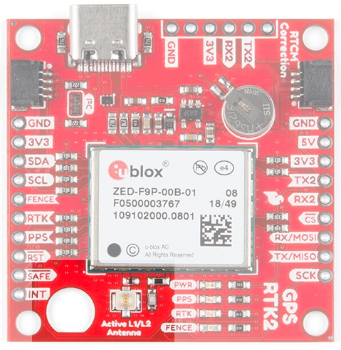
SparkFun GPS-RTK2 board

USB

The USB C connector makes it easy to connect the ZED-F9P to u-center for configuration and quick viewing of NMEA sentences. It is also possible to connect a Raspberry Pi or other SBC over USB. The ZED-F9P enumerates as a serial COM port and it is a seperate serial port from the UART interface. See Getting Started with U-Center for more information about getting the USB port to be a serial COM port.

The USB port highlighted on the ZED-F9P breakout board

A 3.3V regulator is provided to regulate the 5V USB down to 3.3V the module requires. External 5V can be applied or a direct feed of 3.3V can be provided. Note that if you’re provide the board with 3.3V directly it should be a clean supply with minimal noise (less than 50mV VPP ripple is ideal for precision locating).

The 3.3V regulator is capable of sourcing 600mA from a 5V input and the USB C connection is capable of sourcing 2A.

I2C (a.k.a DDC)

The u-blox ZED-F9P has a “DDC” port which is really just an I2C port (without all the fuss of trademark issues). All features are accessible over the I2C ports including reading NMEA sentences, sending UBX configuration strings, piping RTCM data into the module, etc. We’ve written an extensive Arduino library showing how to configure most aspects of the ZED-F9P making I2C our preferred communication method on the ZED. You can get the library through the Arduino library manager by searching ‘SparkFun Ublox’. Checkout the SparkFun U-blox Library section for more information.

The GPS-RTK2 from SparkFun also includes two Qwiic connectors to make daisy chaining this GPS receiver with a large variety of I2C devices. Checkout Qwiic for your next project.

Highlighted I2C port and Qwiic connectors

UART/Serial

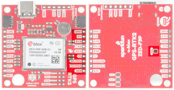
The classic serial pins are available on the ZED-F9P but are shared with the SPI pins. By default, the UART pins are enabled. Be sure the DSEL jumper on the rear of the board is open.

  • TX/MISO = TX out from ZED-F9P
  • RX/MOSI = RX into ZED-F9P

Serial pins on SparkFun ZED-F9P highlighted

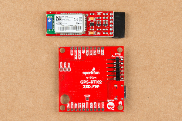
There is a second serial port (UART2) available on the ZED-F9P that is primarily used for RTCM3 correction data. By default, this port will automatically receive and parse incoming RTCM3 strings enabling RTK mode on the board. In addition to the TX2/RX2 pins we have added an additional ‘RTCM Correction’ port where we arranged the pins to match the industry standard serial connection (aka the ‘FTDI’ pinout). This pinout is compatible with our Bluetooth Mate and Serial Basic so you can send RTCM correction data from a cell phone or computer. Note that RTCM3 data can also be sent over I2C, UART1, SPI, or USB if desired.

UART2 and RTCM correction port highlighted on ZED-F9P

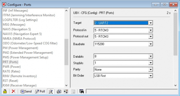
The RTCM correction port (UART2) defaults to 38400bps serial but can be configured via software commands (checkout our Arduino library) or over USB using u-center. Keep in mind our Bluetooth Mate defaults to 115200bps. If you plan to use Bluetooth for correction data (we found it to be easiest), we recommend you increase this port speed to 115200bps using u-center. Additionally, but less often needed, the UART2 can be configured for all types of communication including NMEA output, and UBX binary protocol communication. In generally, we don’t use UART2 for anything but RTCM correction data, so we recommend leaving the in/out protocols as RTCM.

UART2 configuration inside u-center

If you’ve got the ZED-F9P setup for base station mode (also called survey-in mode) the UART2 will output RTCM3 correction data. This means you can connect a radio or wired link to UART2 and the board will automatically send just RTCM bytes over the link (no NMEA data taking up bandwidth).

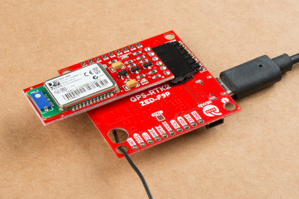
GPS-RTK2 with Bluetooth Mate attached

Base station setup to send RTCM bytes out over Bluetooth

SPI

The ZED-F9P can also be configured for SPI communication. By default, the SPI port is disabled. To enable SPI close the DSEL jumper on the rear of the board. Closing this jumper will disable the UART1 and I2C interfaces (UART2 will continue to operate as normal).

The SPI pins highlighted on the SparkFun RTK2

Control Pins

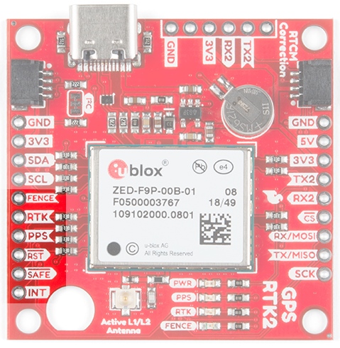
The control pins are highlighted below.

Highlighted control pins of the SparkFun GPS-RTK2

These pins are used for various extra control of the ZED-F9P:

  • FENCE: Geofence output pin. Configured with U-Center. Will go high or low when a geofence is setup. Useful for triggering alarms and actions when the module exits a programmed perimeter.
  • RTK: Real Time Kinematic output pin. Remains high when module is in normal GPS mode. Begins blinking when RTCM corrections are received and module enters RTK float mode. Goes low when module enters RTK fixed mode and begins outputting cm-level accurate locations.
  • PPS: Pulse-per-second output pin. Begins blinking at 1Hz when module gets basic GPS/GNSS position lock.
  • RST: Reset input pin. Pull this line low to reset the module.
  • SAFE: Safeboot input pin. This is required for firmware updates to the module and generally should not be used or connected.
  • INT: Interrupt input/output pin. Can be configured using U-Center to bring the module out of deep sleep or to output an interrupt for various module states.

Antenna

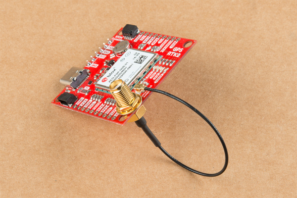
The ZED-F9P requires a good quality GPS or GNSS (preferred) antenna. A U.FL connector is provided. Note: U.FL connectors are rated for only a few mating cycles (about 30) so we recommend you set it and forget it. A U.FL to SMA cable threaded through the mounting hole provides a robust connection that is also easy to disconnect at the SMA connection if needed. Low-cost magnetic GPS/GNSS antennas can be used (checkout the ublox white paper) but a 4” / 10cm metal disc is required to be placed under the antenna as a ground plane.

U.FL antenna connector and SMA cut-out on the SparkFun GPS-RTK2

A cutout for the SMA bulkhead is available for those who want an extra sturdy connection. We recommended installing the SMA into the board only when the board is mounted in an enclosure. Otherwise, the cable runs the risk of being damaged when compressed (for example, students carrying the board loose in a backpack).

SMA inserted and screwed to PCB

LEDs

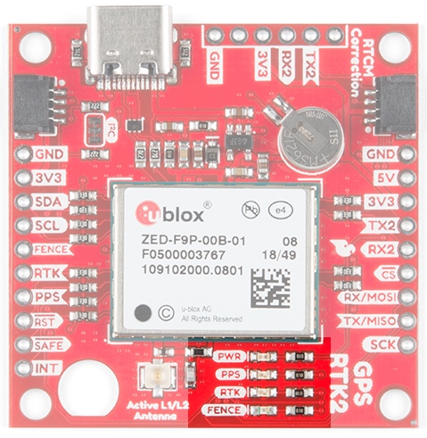
The board includes four status LEDs as indicated in the image below.

SparkFun GPS-RTK2 LEDs

  • PWR: The power LED will illuminate when 3.3V is activated either over USB or via the Qwiic bus.
  • PPS: The pulse per second LED will illuminate each second once a position lock has been achieved.
  • RTK: The RTK LED will be illuminated constantly upon power up. Once RTCM data has been successfully received it will begin to blink. This is a good way to see if the ZED-F9P is getting RTCM from various sources. Once an RTK fix is obtained, the LED will turn off.
  • FENCE: The FENCE LED can be configured to turn on/off for geofencing applications.

Jumpers

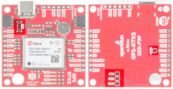
There are five jumpers used to configure the GPS-RTK2.

User jumpers on the SparkFun RTK2

Closing DSEL with solder enables the SPI interface and disables the UART and I2C interfaces. USB will still function.

Cutting the I2C jumper will remove the 2.2k Ohm resistors from the I2C bus. If you have many devices on your I2C bus you may want to remove these jumpers. Not sure how to cut a jumper? Read here!

Cutting the JP1, JP2, JP3 jumpers will disconnect of the various status LEDs from their associated pins.

Backup Battery

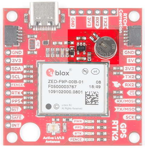
The MS621FE rechargeable battery maintains the battery backed RAM (BBR) on the GNSS module. This allows for much faster position locks. The BBR is also used for module configuration retention. The battery is automatically trickle charged when power is applied and should maintain settings and GNSS orbit data for up to two weeks without power.

The backup battery on the SparkFun RTK2

Connecting an Antenna

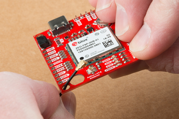
U.FL connectors are very good but they are a designed to be implemented inside a small embedded application like a laptop. Exposing a U.FL connector to the wild risks it getting damaged. To prevent damaging the U.FL connection we recommend threading the U.FL cable through the stand-off hole, then attach the U.FL connectors. This will provide a great stress relief for the antenna connection. Now attach your SMA antenna of choice.

U.FL cable threaded through the standoff hole

Additionally, a bulkhead cut-out is provided to screw the SMA onto the PCB if desired.

SMA inserted and screwed to PCB

While this method decreases stress from the U.FL connector it is only recommended when the board has been permanently mounted. If the board is not mounted, the cable on the U.FL cable is susceptible to being kinked causing impedance changes that may decrease reception quality.

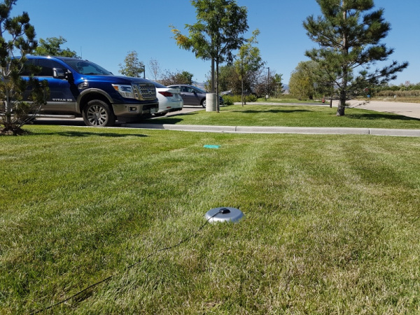
If you’re indoors you must run a SMA extension cable long enough to locate the antenna where it has a clear view of the sky. That means no trees, buildings, walls, vehicles, or concrete metally things between the antenna and the sky. Be sure to mount the antenna on a 4”/10cm metal ground plate to increase reception.

GPS antenna in grass

Connecting the GPS-RTK2 to a Correction Source

Before you go out into the field it’s good to understand how to get RTCM data and how to pipe it to the GPS-RTK2. We recommend you read Connecting a Correction Source section of the original GPS-RTK tutorial. This will give you the basics of how to get a UNAVCO account and how to identify a Mount Point within 10km of where your ZED-F9P rover will be used. This section builds upon these concepts.

For this example, we will show how to get correction data from the UNAVCO network and pull that data in using the Android app called NTRIP Client. The correction data will then be transmitted from the app over Bluetooth to the ZED-F9P using the SparkFun Bluetooth Mate.

Required Materials

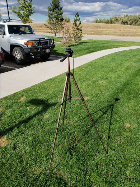
Camera Tripod with GNSS Antenna on Ground Plate

GNSS antenna sitting on a metal ground plate elevated with clear view of the sky

Now setup your GPS receiver such that you can work from your desk but have the antenna outdoors with a clear view of the sky.

Required Software

  • Credentials with a free RTCM provider such as UNAVCO
  • U-Center
  • Get the NTRIP By Lefebure app from Google Play. There seem to be NTRIP apps for iOS but we have not been able to verify any one app in particular. If you have a favorite, please let us know.

First we need to attach the Bluetooth Module to the GPS-RTK2 board. Solder a female header to the Bluetooth Mate so that it hangs off the end.

SparkFun Bluetooth Mate with Female header connection

On the GPS-RTK2 board we recommend soldering the right-angle male header underneath the board. This will allow the Bluetooth module to be succinctly tucked under the board.

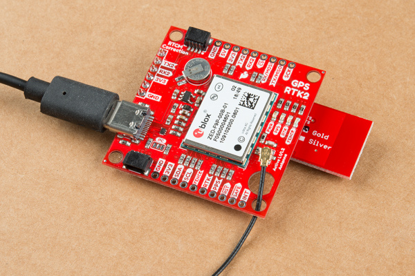
When attaching the Bluetooth Mate to GPS-RTK2 be sure to align the pins so that the GND indicator align on both Bluetooth module and RTK board. Once Bluetooth has been installed attach your GNSS antenna and connect the RTK2 board over USB. This will power the board and the Bluetooth Mate.

RTK2 connected over USB with Bluetooth

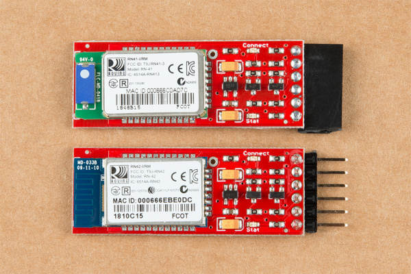
Where the male and female headers go is personal preference. For example, here are two Bluetooth Mates; one with male headers, one with female.

Two Bluetooth Mates with different headers

Soldering a female header to a Bluetooth Mate makes it easier to add Bluetooth to boards that have a ‘FTDI’ style connection like our OpenScale, Arduino Pro, or Simultaneous RFID Reader. Whereas, soldering a male header to the Bluetooth Mate makes it much easier to use in a breadboard. It’s really up to you!

The Bluetooth Mate defaults to 115200bps whereas the RTK2 is expecting serial over UART2 to be 38400bps. To fix this we need to open u-center and change the port settings for UART2. If you haven’t already, be sure to checkout the tutorial Getting Started with U-Center to get your bearings.

Open the Configure window and navigate to the PRT (Ports) section. Drop down the target to UART2 and set the baud rate to 115200. Finally, click on the ‘Send’ button.

Ublox UCenter Port configuration for RTK

By this time you should have a valid 3D GPS lock with ~1.5m accuracy. It’s about to get a lot better.

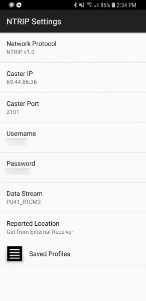
We are going to assume you’ve read the original RTK tutorial and obtained your UNAVCO credentials including the following:

  • Username
  • Password
  • IP Address for UNAVCO (69.44.86.36 at time of writing)
  • Caster Port (2101 at time of writing)
  • Data Stream a.k.a. Mount Point (‘P041_RTCM3’ if you want the one near Boulder, CO - but you should really find one nearest your rover location)

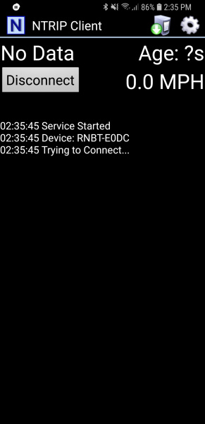
The Bluetooth Mate should be powered up. From your phone, discover the Bluetooth Mate and pair with it. The module used in this tutorial was discovered as RNBT-E0DC where E0DC is the last four characters of the MAC address of the module and should be unique to your module.

Once you have your UNAVCO credentials and you’ve paired with the Bluetooth module open the NTRIP client.

Homescreen of NTRIP Client for Android

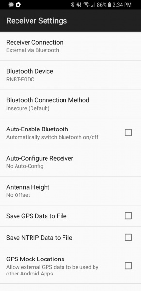
From the home screen, click on the gear in upper right corner then Receiver Settings.

NTRIP Client Receiver Settings

Verify that the Receiver Connection is set to Bluetooth then select Bluetooth Device and select the Bluetooth module you just paired with. Next, open NTRIP settings and enter your credentials including mounting point (a.k.a. Data Stream).

NTRIP Client Server Settings

This example demonstrates how to obtain correction data from UNAVCO’s servers but you could similarly setup your own base station using another ZED-F9P and RTKLIB to broadcast the correction data. This NTRIP app would connect to your RTKLIB based server giving you some amazing flexibility (the base station could be anywhere there’s a laptop and Wifi within 10km of your rover).

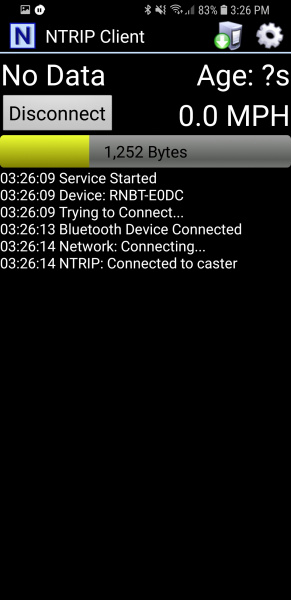
Ok. You ready? This is the fun part. Return to the main NTRIP window and click Connect. The app will connect to the Bluetooth module. Once connected, it will then connect to your NTRIP source. Once data is flowing you will see the number of bytes increase every second.

NTRIP Client downloading correction data

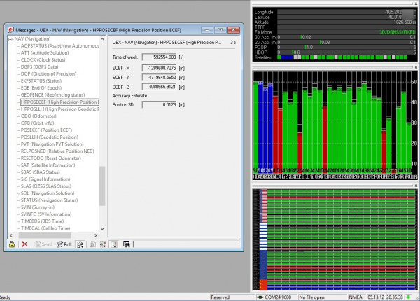
Within a few seconds you should see the RTK LED on the GPS-RTK2 board turn off. This indicates you have an RTK fix. To verify this, open u-center on your computer. The first thing to notice is that Fix Mode in the left hand black window has changed from 3D to 3D/DGNSS/FIXED.

U-center showing 17mm accuracy

Navigate to the UBX-NAV-HPPOSECEF message. This will show you a high-precision 3D accuracy estimate. We were able to achieve 17mm accuracy using a low-cost GNSS antenna with a metal plate ground plane and we were over 10km from the correction station.

Congrats! You now know where you are within the diameter of a dime!

SparkFun U-blox Library

Note: This example assumes you are using the latest version of the Arduino IDE on your desktop. If this is your first time using Arduino, please review our tutorial on installing the Arduino IDE. If you have not previously installed an Arduino library, please check out our installation guide.

The SparkFun Ublox Arduino library enables the reading of all positional datums as well as sending binary UBX configuration commands over I2C. This is helpful for configuring advanced modules like the ZED-F9P but also the NEO-M8P-2, SAM-M8Q and any other Ublox module that use the Ublox binary protocol.

The SparkFun U-blox Arduino library can be downloaded with the Arduino library manager by searching ‘SparkFun Ublox’ or you can grab the zip here from the GitHub repository:

SparkFun U-blox Arduino Library (ZIP)

Once you have the library installed checkout the various examples.

  • Example1: Read NMEA sentences over I2C using Ublox module SAM-M8Q, NEO-M8P, etc
  • Example2: Parse NMEA sentences using MicroNMEA library. This example also demonstrates how to overwrite the processNMEA function so that you can direct the incoming NMEA characters from the Ublox module to any library, display, radio, etc that you prefer.
  • Example3: Get latitude, longitude, altitude, and satellites in view (SIV). This example also demonstrates how to turn off NMEA messages being sent out of the I2C port. You’ll still see NMEA on UART1 and USB, but not on I2C. Using only UBX binary messages helps reduce I2C traffic and is a much lighter weight protocol.
  • Example4: Displays what type of a fix you have the two most common being none and a full 3D fix. This sketch also shows how to find out if you have an RTK fix and what type (floating vs. fixed).
  • Example5: Shows how to get the current speed, heading, and dilution of precision.
  • Example6: Demonstrates how to increase the output rate from the default 1 per second to many per second; up to 30Hz on some modules!
  • Example7: Older modules like the SAM-M8Q utilize an older protocol (version 18) whereas the newer modules like the ZED-F9P depricate some commands using the latest protocol (version 27). This sketch shows how to query the module to get the protocol version.
  • Example8: Ublox modules use I2C address 0x42 but this is configurable via software. This sketch will allow you to change the module’s I2C address.
  • Example9: Altitude is not a simple measurement. This sketch shows how to get both the ellipsoid based altitude and the MSL (mean sea level) based altitude readings.
  • Example10: Sometimes you just need to do a hard reset of the hardware. This sketch shows how to set your Ublox module back to factory default settings.
  • NEO-M8P Example1: Send UBX binary commands to enable RTCM sentences on U-blox NEO-M8P-2 module. This example is one of the steps required to setup the NEO-M8P as a base station. For more information have a look at the Ublox manual for setting up an RTK link.
  • NEO-M8P Example2: This example extends the previous example sending all the commands to the NEO-M8P-2 to have it operate as a base. Additionally the processRTCM function is exposed. This allows the user to overwrite the function to direct the RTCM bytes to whatever connection the user would like (radio, serial, etc).
  • ZED-F9P Example1: This module is capable of high precision solutions. This sketch shows how to inspect the accuracy of the solution. It’s fun to watch our location accuracy drop into the millimeter scale.
  • ZED-F9P Example2: The ZED-F9P uses a new Ublox configuration system of VALGET/VALSET/VALDEL. This sketch demonstrates the basics of these methods.
  • ZED-F9P Example3: Setting up the ZED-F9P as a base station and outputting RTCM data.

This SparkFun Ublox library really focuses on I2C because it’s faster than serial and supports daisy-chaining. The library also uses the UBX protocol because it requires far less overhead than NMEA parsing and does not have the precision limitations that NMEA has.

Setting the GPS-RTK2 as a Correction Source

If you’re located further than 20km from a correction station you can create your own station using the ZED-F9P. Ublox provides a setup guide within the ZED-F9P Integration Manual showing the various settings needed via U-Center. We’ll be covering how to setup the GPS-RTK2 using I2C commands only. This will enable a headless (computerless) configuration of a base station that outputs RTCM correction data.

Before getting started we recommend you configure the module using U-Center. Checkout our tutorial on using U-Center then read section 3.5.8 Base Station Configuration of the Ublox Integration Manual for getting the ZED-F9P configured for RTK using U-Center. Once you’ve been successful controlling the module in the comfort of your lab using U-Center, then consider heading outdoors.

For this exercise we’ll be using the following parts:

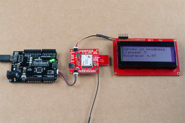
The ZED-F9P can be configured using Serial, SPI, or I2C. We’re fans of the daisychain-ability of I2C so we’ll be focusing on the Qwiic system. For this exercise we’ll be connecting the an LCD and GPS-RTK2 to a BlackBoard using two Qwiic cables.

ZED-F9P in survey in mode

For the antenna, you’ll need a clear view of the sky. The better your antenna position the better your accuracy and performance of the system. We designed the GPS Antenna Ground Plate to make this setup easy. The plate has a ¼” threaded hole that threads directly onto a camera tripod. The plate thickness was chosen to be thick enough so that the threaded screw is flush with the plate so it won’t interfere with the antenna. Not sure why we’re using a ground plate? Read the Ublox white paper on using low-cost GNSS antennas with RTK. Mount your magnetic mount antenna and run the SMA cable to the U.FL to SMA cable to the GPS-RTK2 board.

GPS RTK antenna on camera tripod

There are only three steps to initiating a base station:

  • Enable Survey-In mode for 1 minute (60 seconds)
  • Enable RTCM output messages
  • Being Transmitting the RTCM packets over the backhaul of choice

Be sure to grab the SparkFun Arduino Library for Ublox. You can easily install this via the library manager by searching ‘SparkFun Ublox’. Once installed click on File->Examples->SparkFun_Ublox_Arduino_Library.

The ZED-F9P subfolder houses a handful of sketches specific to its setup. Example3 of the library demonstrates how to send the various commands to the GPS-RTK2 to enable Survey-In mode. Let’s discuss the important bits of code.

language:c
response = myGPS.enableSurveyMode(60, 5.000); //Enable Survey in, 60 seconds, 5.0m

The library is capable of sending UBX binary commands with all necessary headers, packet length, and CRC bytes over I2C. The enableSurveyMode(minimumTime, minimumRadius) command does all the hard work to tell the module to go into survey mode. The module will begin to record lock data and calculate a 3D standard deviation. The survey-in process ends when both the minimum time and minimum radius are achieved. Ublox recommends 60 seconds and a radius of 5m. With a clear view of the sky, with a low cost GNSS antenna mounted to a ground plate we’ve seen the survey complete at 61 seconds with a radius of around 1.5m.

language:c
response &= myGPS.enableRTCMmessage(UBX_RTCM_1005, COM_PORT_I2C, 1); //Enable message 1005 to output through I2C port, message every second
response &= myGPS.enableRTCMmessage(UBX_RTCM_1074, COM_PORT_I2C, 1);
response &= myGPS.enableRTCMmessage(UBX_RTCM_1084, COM_PORT_I2C, 1);
response &= myGPS.enableRTCMmessage(UBX_RTCM_1094, COM_PORT_I2C, 1);
response &= myGPS.enableRTCMmessage(UBX_RTCM_1124, COM_PORT_I2C, 1);
response &= myGPS.enableRTCMmessage(UBX_RTCM_1230, COM_PORT_I2C, 10); //Enable message every 10 seconds

These six lines enable the six RTCM output messages needed for a second GPS-RTK2 to receive correction data. Once these sentences have been enabled (and assuming a survey process is complete) the GPS-RTK2 base module will begin outputting RTCM data every second after the NMEA sentences (the RTCM_1230 sentence will be output once every 10 seconds). You can view an example of what this output looks like here.

The size of the RTCM correction data varies but in general it is approximately 2000 bytes every second (~2500 bytes every 10th second when 1230 is transmitted).

language:c
//This function gets called from the SparkFun Ublox Arduino Library.
//As each RTCM byte comes in you can specify what to do with it
//Useful for passing the RTCM correction data to a radio, Ntrip broadcaster, etc.
void SFE_UBLOX_GPS::processRTCM(uint8_t incoming)
{
  //Let's just pretty-print the HEX values for now
  if (myGPS.rtcmFrameCounter % 16 == 0) Serial.println();
  Serial.print("");
  if (incoming < 0x10) Serial.print("0");
  Serial.print(incoming, HEX);
}

If you have a ‘rover’ in the field in need of correction data you’ll need to get the RTCM bytes to the rover. The SparkFun Ublox library automatically detects the difference between NMEA sentences and RTCM data. The processRTCM() function allows you to ‘pipe’ just the RTCM correction data to the channel of your choice. Once the base station has completed the survey and has the RTCM messages enabled, your custom processRTCM() function can pass each byte to any number of channels:

  • A wireless system such as LoRa or Cellular
  • Posting the bytes over the internet using WiFi or wired ethernet over an Ntrip caster
  • Over a wired solution such as RS485

The power of the processRTCM() function is that it doesn’t care; it presents the user with the incoming byte and is agnostic about the back channel.

Heads up! We’ve been experimenting with various LoRa solutions and the bandwidth needed for the best RTCM (~500 bytes per second) is right at the usable byte limit for many LoRa setups. It’s possible but you may need to adjust your LoRa settings to reach the throughput necessary for RTK.

What about configuring the rover? Ublox designed the ZED-F9P to automatically go into RTK mode once RTCM data is detected on any of the ports. Simply push the RTCM bytes from your back channel into one of the ports (UART, SPI, I2C) on the rover’s GPS-RTK2 and the location accuracy will go from meters to centimeters. The rover’s NMEA messages will contain the improved Lat/Long data and you’ll know where you are with mind-bending accuracy. It’s a lot of fun to watch!

Can I Really Use NMEA with a High Precision GPS Receiver?

Yes! Except that NMEA sentences are right on the edge of enough precision. NMEA sentences look something like this:

language:bash
$GNGGA,012911.00,4003.19080,N,10416.95542,W,1,12,0.75,1647.1,M,-21.3,M,,*4F

NMEA outputs coordinates in the ddmm.mmmmm format. So what is the weight of the least significant digit? Said differently, what is the impact of one digit change?

language:bash
104 16.95542

vs

language:bash
104 16.95543

If we know 1 degree of latitude is 111.3km at the equator, we can glean the change of a fraction of a minute:

  • 1 degree = 60 minutes
  • 1 minute = 1 degree/60 = 111.32km / 60 = 1.855km
  • 1 minute = 1855m
  • 0.1min = 185.5m
  • 0.01min = 18.55m
  • 0.001min = 1.855m
  • 0.0001min = .1855m = 185.5mm
  • 0.00001min = 0.0185m = 18.55mm = 1.855cm

Using the NMEA sentence, the ZED-F9P will only be able to communicate a change of ~1.5cm location change for each digit in the 5th position. This is pretty close to the 1.0cm accuracy of the module. If you want additional precision, you should consider using the UBX protocol which can output up to 8 digits of precision in dd.dddddddd format which will get you down to 1.11mm of precision! Be sure to checkout the examples in the SparkFun Ublox Arduino Library. We have various examples outputting the full 8 digits of precision over I2C without the burden of parsing NMEA sentences.

Resources and Going Further

Have fun with your new found super power: sub decimeter grade GPS!

For more on the GPS-RTK2, check out the links below:

Need some inspiration? Check out some of these related tutorials:

Building an Autonomous Vehicle: The Batmobile

Documenting a six-month project to race autonomous Power Wheels at the SparkFun Autonomous Vehicle Competition (AVC) in 2016.

What is GPS RTK?

Learn about the latest generation of GPS and GNSS receivers to get 2.5cm positional accuracy!

GPS-RTK Hookup Guide

Find out where you are! Use this easy hook-up guide to get up and running with the SparkFun high precision GPS-RTK board.

Getting Started with U-Center

Learn the tips and tricks to use the u-blox software tool to configure your GPS receiver.

learn.sparkfun.com | CC BY-SA 3.0 | SparkFun Electronics | Niwot, Colorado


LilyPad Vibe Board Hookup Guide

$
0
0

LilyPad Vibe Board Hookup Guide a learn.sparkfun.com tutorial

Available online at: http://sfe.io/t667

Introduction

The LilyPad Vibe Board is a small vibration motor that can be sewn into projects with conductive thread and controlled by a LilyPad Arduino. The board can be used as a physical indicator on clothing and costumes for haptic feedback.

LilyPad Vibe Board

LilyPad Vibe Board

DEV-11008
$6.95

Required Materials

To follow along with this tutorial, you will need the following materials. You may not need everything though depending on what you have. Add it to your cart, read through the guide, and adjust the cart as necessary.

Suggested Reading

If you aren’t familiar with the following concepts, we recommend checking out these tutorials before continuing.

What is an Arduino?

What is this 'Arduino' thing anyway?

LilyPad Basics: E-Sewing

Learn how to use conductive thread with LilyPad components.

LilyPad ProtoSnap Plus Hookup Guide

The LilyPad ProtoSnap Plus is a sewable electronics prototyping board that you can use to learn circuits and programming with Arduino, then break apart to make an interactive fabric or wearable project.

Getting Started with LilyPad

An introduction to the LilyPad ecosystem - a set of sewable electronic pieces designed to help you build soft, sewable, interactive e-textile projects.

Attaching to a LilyPad Arduino

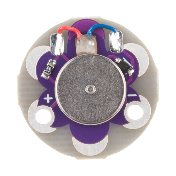
The LilyPad Vibe Board has two sew tabs: Power (+) and Ground (). Next to each tab is a white label for reference. For power, you can connect an input voltage anywhere between 3.3V and 5V. The motor can vibrate faster as you provide more voltage. We recommend connecting the (+) tab to a MOSFET to drive the motor when using it with an Arduino due to the amount of current each I/O pin can source . To adjust the intensity, we recommend using a PWM capable sew tab on a LilyPad Arduino.

LilyPad Vibe Board top view

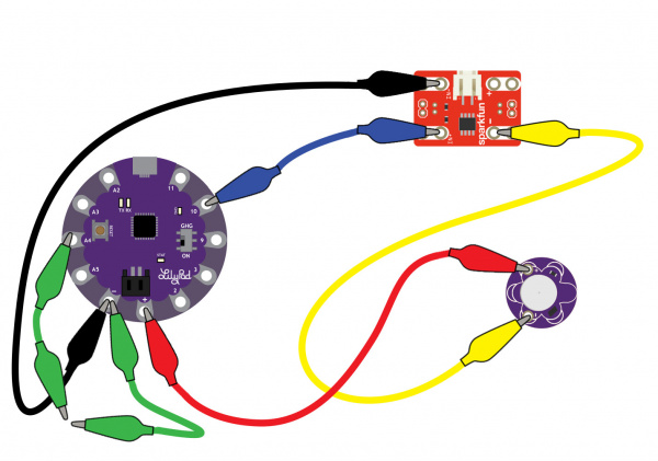
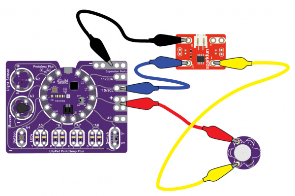
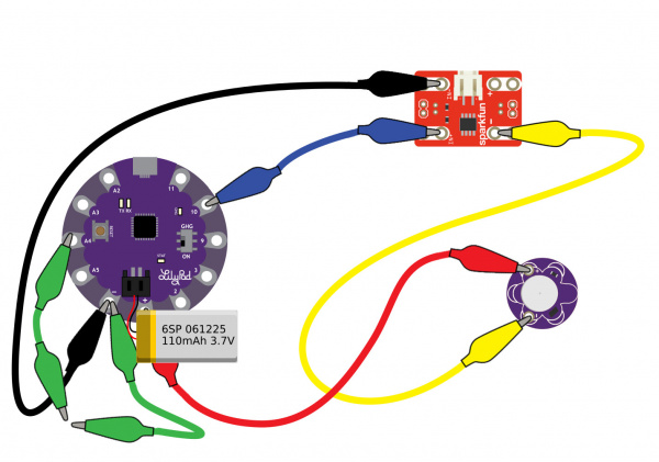
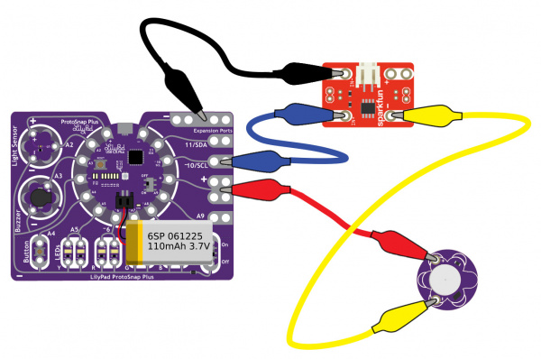
To follow along with the code examples in this tutorial, connect the vibe board and transistor to a LilyPad Arduino as shown in the images below. Use alligator clips to temporarily connect the circuit. Connect the LilyPad's “+” sew tab to the “+” sew tab of the vibe board. Make another connection between the “” sew tab and the MOSFET power controller's “” sew tab. Keep in mind that the “” label on the MOSFET power controller does not represent ground (GND or “”). Ground is represented as “IN–”. The “IN–” should be connected to a LilyPad Arduino's “” sew tab.

To control the vibe board, connect a PWM pin (pin 10 in the following cases) to the “IN+”. When testing the example for button feedback, simply connect A4 to the LilyPad Arduino's “” ground sew tab. After you are finished prototyping, replace the alligator clips with conductive thread traces for permanent connection in your project.

LilyPad Arduino USB with N-Channel MOSFET Power Controller and Vibe Motor

Connecting to a LilyPad Arduino USB (Click image to enlarge).

LilyPad Protosnap Plus with N-Channel MOSFET Power Controller and Vibe Motor

Connecting to a LilyPad ProtoSnap Plus (Click image to enlarge).

Using a Button to Trigger Feedback

Note: This example assumes you are using the latest version of the Arduino IDE on your desktop. If this is your first time using Arduino, please review our tutorial on installing the Arduino IDE. If you have not previously installed an Arduino library, please check out our installation guide.

Copy the code below and paste it into your Arduino IDE. Select your board (i.e. LilyPad Arduino USB for the LilyPad USB, LilyPad USB Plus for the LilyPad USB Plus, etc.) and COM port. Finally, click the upload button to upload the demo on your Arduino.

language:c
/*
  LilyPad Vibe Board: Button Feedback
  Written by: Ho Yun "Bobby" Chan
  @ SparkFun Electronics
  Date: 1/14/2019
  https://www.sparkfun.com/products/11008

  The main code checks for a button press. If there is a button press,
  the Arduino turns on the LilyPad Vibe Board for haptic feedback.
  For a visual cue, the LED will turn on too. If not, the LED and
  motor will remain off.
*/

const int motorPin = 10;     // motor connected to PWM pin 9
const int button1Pin = A4;  // pushbutton 1 pin
const int ledPin =  13;     // LED pin

int button1State;  //check state of button press

void setup() {
  //Serial.begin(9600); //setup serial monitor, uncomment Serial.print()'s to debug
  //Serial.println("Begin LilyPad Vibe Motor Tests");

  pinMode(button1Pin, INPUT_PULLUP);//set internal pull up for button
  pinMode(ledPin, OUTPUT); //visual feedback


  //Quick Test 1: Check If LED and Motor Can Turn On

  //Serial.println("Turn LilyPad Vibe Motor And LED ON");
  //digitalWrite(ledPin, HIGH);  // turn the LED on
  analogWrite(motorPin, 255);  //turn motor
  delay(300);

  //Serial.println("Turn LilyPad Vibe Motor And LED OFF");
  //digitalWrite(ledPin, LOW);  // turn the LED off
  analogWrite(motorPin, 0);   //turn motor off
  delay(300);

  //Quick Test 2: Check Intensity of Motor (turns on at about 130
  // fade in from min to max in increments of 5 points:
  for (int fadeValue = 0 ; fadeValue <= 255; fadeValue += 5) {
    // sets the value (range from 0 to 255):
    analogWrite(motorPin, fadeValue);
    //Serial.print("LilyPad Vibe Motor Intensity = ");
    //Serial.println(fadeValue);

    // wait for 100 milliseconds to see motor
    delay(100);
  }
  // fade out from max to min in increments of 5 points:
  for (int fadeValue = 255 ; fadeValue >= 0; fadeValue -= 5) {
    // sets the value (range from 0 to 255):
    analogWrite(motorPin, fadeValue);
    //Serial.print("LilyPad Vibe Motor Intensity = ");
    //Serial.println(fadeValue);

    // wait for 100 milliseconds to see motor
    delay(100);
  }

}

void loop() {
  // Here we'll read the current pushbutton states into
  // a variable:

  // Remember that if the button is being pressed, it will be
  // connected to GND. If the button is not being pressed,
  // the pullup resistor will connect it to Vcc.

  // So the state will be LOW when it is being pressed,
  // and HIGH when it is not being pressed.

  // Now we'll use those states to control the LED.
  // Here's what we want to do:

  button1State = digitalRead(button1Pin);

  if (button1State == LOW)  // if we're pushing button 1
  {
    //Serial.println("Button has been pressed, turn LilyPad Vibe Motor And LED ON");
    digitalWrite(ledPin, HIGH);  // turn the LED on
    analogWrite(motorPin, 255);  //turn motor on
    delay(300);                  //slight delay for feedback
  }
  else
  {
    digitalWrite(ledPin, LOW);  // turn the LED
    analogWrite(motorPin, 0);   //turn motor off
    delay(300);
  }
}

After uploading, you should see the built-in LED on the LilyPad Arduino and the vibe motor turn on and off. The LilyPad Arduino will then slowly increase and decrease in intensity. The vibe motor will turn on when the Arduino's PWM output is around 130. Once we start looping in the loop() function, the LilyPad Arduino will check to see if there is a button press. If the button is pressed (i.e. or when A4 is connected to ground), the built-in LED and vibe motor will turn on. There is a slightly longer delay after this happens so there is enough time to detect when the motor is turned on as feedback. If there is no button press, both will remain off.

Sewing Into a Project

Once you are finished prototyping your project using the LilyPad Vibe Board, you can replace any temporary connections with conductive thread. For an overview of sewing with conductive thread, check out this guide:

LilyPad Basics: E-Sewing

December 17, 2016

Learn how to use conductive thread with LilyPad components.

You can also make your own button by using metal snaps or any conductive material.

LDK Experiment 5: Make Your Own Switch

October 2, 2013

Learn to create and integrate your own handmade switch into an e-textile circuit.

Making Your Project Portable with Batteries

As you start embedding your circuit into your project, we recommend connecting a LiPo battery to the LilyPad's JST connector to regulate the voltage. There are also LiPo charge IC's built into LilyPad Arduinos to recharge the LiPo batteries so that it does not have to be removed from the circuit.

LilyPad Arduino USB, MOSFET Power Controller, and Vibe Board with LiPo BatteryLilyPad Protosnap Plus: MOSFET Power Controller, and Vibe Board with LiPo Battery
Circuits with LiPo batteries for remote power. Click on images for a closer view.

For more information about using LiPo batteries with LilyPad, check out the tutorial for Powering Your Project.

LilyPad Basics: Powering Your Project

September 24, 2018

Learn the options for powering your LilyPad projects, LiPo battery safety and care, and how to calculate and consider power constraints on your projects.

Project Examples

Thermal Alert Project

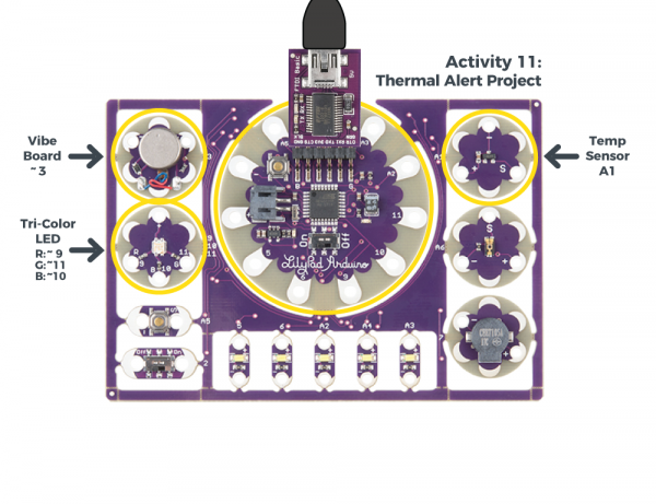
By adding a temperature sensor to the circuit, you can trigger the motor whenever it gets too hot. For more information, check out the thermal alert project from the Lilypad Development Board Activity Guide. Just make sure to redefine the LilyPad Arduino's pins in code.

Thermal Alert Project from the LilyPad Development Board Actibity Guide

Highlighted components used for the thermal alert project. Click on the image for more information.

LilyPad Simblee Fitness Bracer

This fitness bracer uses two vibe boards to alert the wearer when they have been inactive for 60 minutes.

Demo video of the Bluetooth Fitness Bracer project.

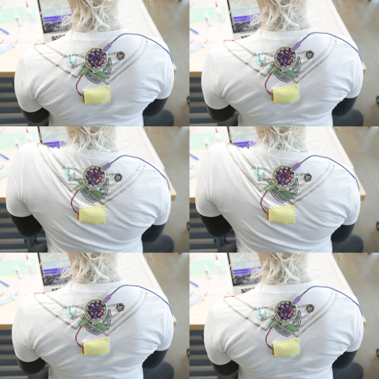
Slouch Alert Shirt by Lara Grant

This posture-sensing wearable is built with a LilyPad, conductive fabric, and vibe board provides feedback when your shoulders hunch forward. Learn how to build this project and more wearables with LilyPad in the Instructables Wearable Electronics class.

Slouch Alert Shirt GIF

GIF of finished Slouch Alert shirt project courtesy of Wearable Electronics Class.

Bats Have Feelings Too by Lynne Bruning

Lynne created a jacket that uses an LV-MaxSonar ultrasonic range finder, LilyPad Arduino, and vibe board to alert the wearer to solid objects in their path.

Model wearing Bats Have Feelings Too - a haptic jacket for the blind

“Bats have feelings too” coat, a haptic coat for the blind. Photo by Carl Snider.

Bristlebots

The LilyPad Vibe Motor is not limited to just haptic feedback. You can also build a neat little bristle bot with the vibe motor, battery holder, and coin cell. You can even add a light sensor and MOSFET to have the robot react to your environment!

Resources and Going Further

Here are some resources for e-textiles and planning a project with the LilyPad Vibe board.

Or, you can check out some of our other wearables tutorials:

Light Up Silk Flower Corsage

Combine a silk flower with a built-in RGB LED and some LilyPad Switches to create a customizable accessory.

Pokémon Go Patches with EL Panels

Add a cloth stencil over EL panels to create glowing logos and designs.

Glowing Pin

Create a quick and easy piece of e-textile art using a LilyPad LED, battery holder, conductive thread, and coin cell battery.

LED Crystal Goddess Crown

Follow this tutorial to make your own Crystal Goddess Crown with LEDs!

Looking for more information about haptic motors and wearable project ideas? Check out the following tutorials.

Insulation Techniques for e-Textiles

Learn a few different ways to protect your conductive thread and LilyPad components in your next wearables project.

Planning a Wearable Electronics Project

Tips and tricks for brainstorming and creating a wearables project.

Haptic Motor Driver Hook-Up Guide

Good vibes only. Getting started with the Haptic Motor Driver.

Or check out some of the following projects for more tutorials and ideas.


learn.sparkfun.com | CC BY-SA 3.0 | SparkFun Electronics | Niwot, Colorado

LuMini Ring Hookup Guide

$
0
0

LuMini Ring Hookup Guide a learn.sparkfun.com tutorial

Available online at: http://sfe.io/t841

Introduction

The LuMini rings (3 inch, 2 inch, 1 inch) are a great way to add a ring of light to just about anything.

SparkFun LuMini LED Ring - 3 Inch (60 x APA102-2020)

SparkFun LuMini LED Ring - 3 Inch (60 x APA102-2020)

COM-14965
$25.95
SparkFun LuMini LED Ring - 2 Inch (40 x APA102-2020)

SparkFun LuMini LED Ring - 2 Inch (40 x APA102-2020)

COM-14966
$15.99
SparkFun LuMini LED Ring - 1 Inch (20 x APA102-2020)

SparkFun LuMini LED Ring - 1 Inch (20 x APA102-2020)

COM-14967
$9.95

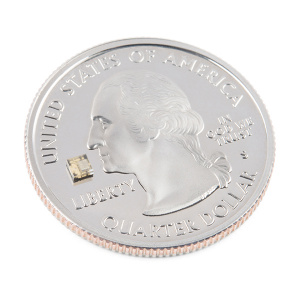
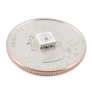
The LuMini line uses the same LED used on our Lumenati boards, the APA102, just in a smaller, 2.0x2.0 mm package. This allows for incredibly tight pixel densities, and thus, a more continuous ring of color. While the LuMini Rings come in different sizes, they all operate in a similar fashion.

Size of a APA102-2020 PackageAPA102, 5050 Package
Size of a APA102, 2020 PackageSize of a APA102, 5050 Package

In this tutorial, we’ll go over how to connect the LuMini rings up to more LuMini rings as well as other APA102 based products. We’ll check out how to map out a ring of lights in software so we can get a little more creative with circular animations. We’ll go over some things to consider as you string more and more lights together, and we’ll also go over some neat lighting patterns to get you away from that standard rainbow pattern (if you have 16 million colors why would you use 255).

Required Materials

To follow along with this tutorial, you will need the following materials. You may not need everything though depending on what you have. Add it to your cart, read through the guide, and adjust the cart as necessary.

Choosing a Microcontroller

You’ll need a microcontroller to control everything, however, there’s a few things to consider when picking one out for the purpose of controlling a whole ton of LED’s. The first thing is that, although they don’t have to operate at a specific timing, APA102 LED’s can transmit data really, really fast for LED’s, like 20 MHz fast. So you should use a microcontroller fast enough to take advantage of this fact. Another thing to consider when you start getting into higher LED counts is the amount of RAM taken up by the LED frame. Each LED takes up 3 bytes of space in RAM, which doesn’t sound like a lot, but if you’re controlling 5000 LED’s, well, you might need something with a bit more RAM than your traditional RedBoard. The below chart outlines the amount of LED’s where you may start running into memory issues. Keep in mind that these are very generous estimates and will decrease depending on what other global variables are declared.

MicrocontrollerMax LED'sClock Speed
SparkFun RedBoard60016 MHz
Arduino Mega 2560260016 MHz
Pro Micro70016 MHz
SparkFun ESP8266 Thing27,000160 MHz
SparkFun ESP32 Thing97,000160 MHz or 240 MHz
Teensy 3.687,000180 MHz (240 MHz Overclock)

It’s pretty easy to choose the ESP or Teensy when it comes to stuff like this, as you’ve got a ton of overhead in clock cycles to run wacky calculations for animations. However, if your project isn’t all about lights, and you’re just tossing a LuMini Ring on a project as an indicator, less powerful microcontrollers will suffice. Here are a few microcontrollers listed from the catalog. Depending on the development board, you may need to solder headers based on your personal preference.

SparkFun RedBoard - Programmed with Arduino

SparkFun RedBoard - Programmed with Arduino

DEV-13975
$19.95
39
Pro Micro - 5V/16MHz

Pro Micro - 5V/16MHz

DEV-12640
$19.95
70
SparkFun ESP32 Thing

SparkFun ESP32 Thing

DEV-13907
$21.95
60
Arduino Mega 2560 R3

Arduino Mega 2560 R3

DEV-11061
$38.95
53
Teensy 3.6 (Headers)

Teensy 3.6 (Headers)

DEV-14058
$33.25
5
SparkFun ESP8266 Thing - Dev Board (with Headers)

SparkFun ESP8266 Thing - Dev Board (with Headers)

WRL-13804
$17.95
6

Selecting a Power Supply

In most cases, your LED installation is gonna pull more than your board can handle (Depending on brightness and animation, anywhere from 100-250 LED’s can be too much for your board’s voltage regulator to handle) so you should snag a sweet 5V power supply that’s got enough wattage in the cottage for all of your LED’s. Here are a few 5V power supplies listed in our catalog. Just make sure to get the appropriate cable and adapter when connecting to your power hungry LEDs.

Wall Adapter Power Supply - 5V DC 2A (Barrel Jack)

Wall Adapter Power Supply - 5V DC 2A (Barrel Jack)

TOL-12889
$5.95
15
Mean Well Switching Power Supply - 5VDC, 20A

Mean Well Switching Power Supply - 5VDC, 20A

TOL-14098
$25.95
Mean Well LED Switching Power Supply - 5VDC, 5A

Mean Well LED Switching Power Supply - 5VDC, 5A

TOL-14601
$14.95

You can either estimate the necessary size of your power supply by taking the amount of LED’s and multiplying by 60 mA (0.06 A) which is the amount of current it takes to run an LED at full white. This calculation will give you the maximum amount of power your LED’s could draw, but most of the time, this is a gross overestimate of the amount of power you’ll actually end up consuming. Instead of calculating, I usually like to test my completed installation on a benchtop power supply using the brightest animation it’ll be running, and then add 20 or 30 percent to give myself a little wiggle room if I want to turn the brightness up in the future.

Power Supply - 80W DC Switching Mode

Power Supply - 80W DC Switching Mode

TOL-09291
$259.95
1

Tools

You will need a wire stripper, wire, soldering iron, solder, general soldering accessories. Tweezers are optional if you are soldering the surface mount decoupling capacitor to the back of the board.

Hook-Up Wire - Assortment (Solid Core, 22 AWG)

Hook-Up Wire - Assortment (Solid Core, 22 AWG)

PRT-11367
$16.95
29
Weller WLC100 Soldering Station

Weller WLC100 Soldering Station

TOL-14228
$44.95
Tweezers - Curved (ESD Safe)

Tweezers - Curved (ESD Safe)

TOL-10602
$3.95
5
Solder Lead Free - 15-gram Tube

Solder Lead Free - 15-gram Tube

TOL-09163
$3.50
2
Wire Strippers - 20-30AWG

Wire Strippers - 20-30AWG

TOL-14763
$14.95
1

Suggested Reading

If you aren’t familiar with the following concepts, we recommend checking out these tutorials before continuing.

Light

Light is a useful tool for the electrical engineer. Understanding how light relates to electronics is a fundamental skill for many projects.

How to Power a Project

A tutorial to help figure out the power requirements of your project.

Light-Emitting Diodes (LEDs)

Learn the basics about LEDs as well as some more advanced topics to help you calculate requirements for projects containing many LEDs.

Electric Power

An overview of electric power, the rate of energy transfer. We'll talk definition of power, watts, equations, and power ratings. 1.21 gigawatts of tutorial fun!

How to Work with Jumper Pads and PCB Traces

Handling PCB jumper pads and traces is an essential skill. Learn how to cut a PCB trace, add a solder jumper between pads to reroute connections, and repair a trace with the green wire method if a trace is damaged.

Hardware Overview

I/O Pins

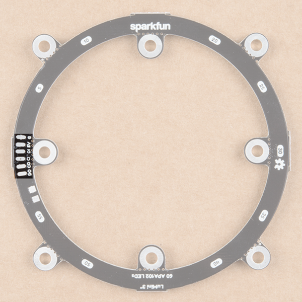
The LuMini rings are powered and controlled using a few pads on the back of each board. Each board has a set of pads for 5V and ground, a set of pads for data and clock input, and a set of pads for data and clock output. These pads are outlined in the below image.

I/O Pads

I/O Pads

Decoupling Capacitor Pads

In larger installations you may need to add a decoupling capacitor between power and ground to prevent voltage dips when turning on a whole bunch of LED’s simultaneously. The spot to add this optional capacitor is outlined below.

Capacitor Pads

Capacitor Pads

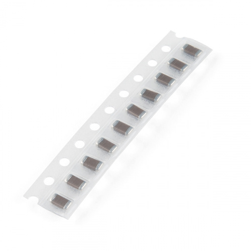
We’d recommend the surface mount 4.7 µF capacitor that is shown below. If you’ve never done surface mount soldering before, this part might be a little tricky, but check out our SMD tips and tricks on doing just that.

Capacitor 4.7uF - SMD (Strip of 10)

Capacitor 4.7uF - SMD (Strip of 10)

COM-15169
$1.95

LED Numbers

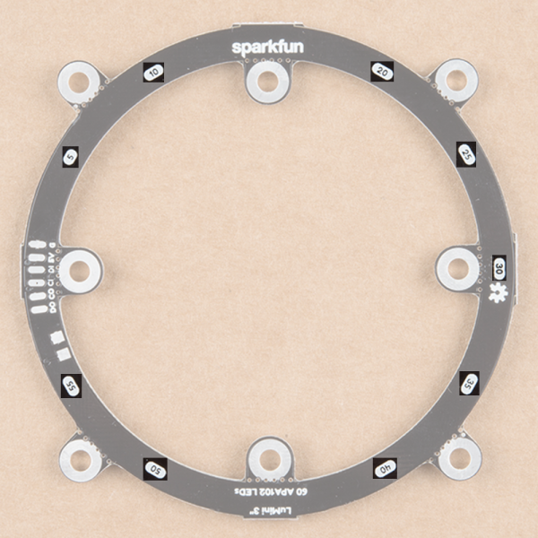
Looking at the back of each ring, you’ll also see some numbers. Since the ring acts like a string of LEDs, these numbers correspond to the LED number in the string. Note that, like the led array, we index at LED 0, so calling leds[5] will correspond to the LED on the opposite side of the 5 labeling.

LED Numbers

LED Numbers

Hardware Assembly

Soldering to the LuMini Rings

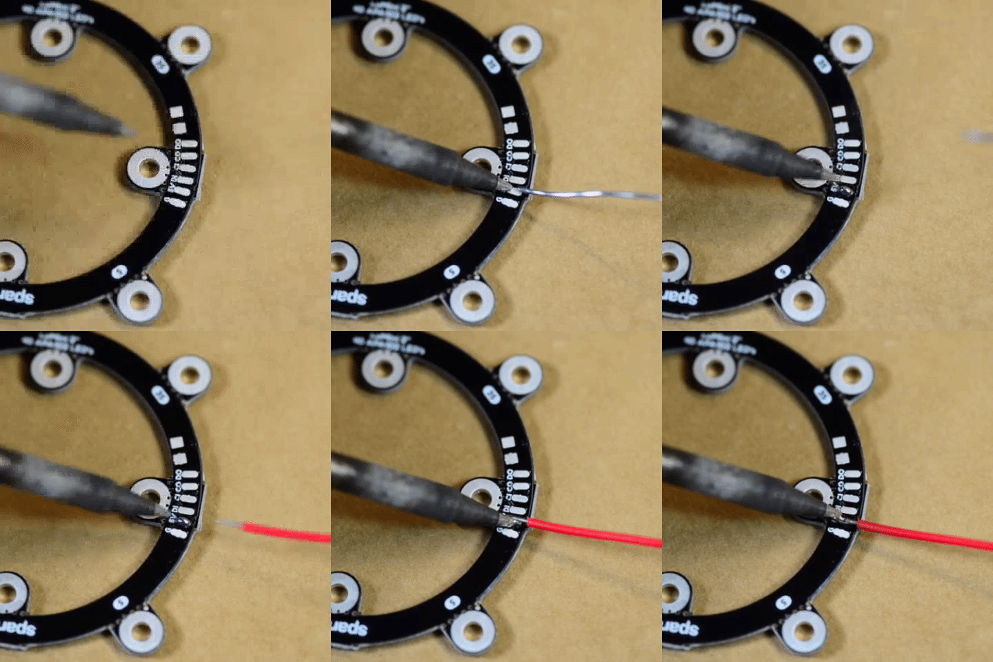
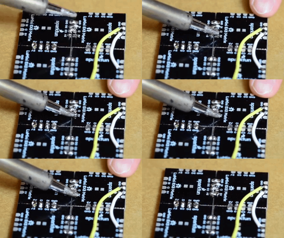
Soldering wires to the pads on the LuMini rings is pretty simple. The trick is simply to pre-solder both the pad and stripped wire before attempting to solder the two together. Then, press the wire onto the pad and solder away! Check out the below GIF if you’re a little confused.

Soldering

Soldering to the LuMini Ring

Choosing Pins

The APA102 LED is controlled on an SPI-like protocol, so it’s generally good practice to connect CI to SCLK on your microcontroller, and connect DI to MOSI. However, This setup isn’t required, and you can connect data and clock up to most pins on your microcontroller. Go ahead and determine which pins you will use, and solder your Data (DI) and Clock (CI) lines into your microcontroller.

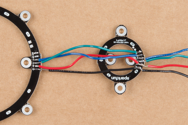
Now that we know how to solder to these pads, we can start making a chain of LuMini rings, or even chain them to other APA102 based products. To do this, all we’ll need to do is solder CO and DO of one ring to the CI and DI of the next ring. The below image has the output of a 1 inch ring connected to the input of a 3 inch ring.

Chained Rings

Chained Rings

Software Installation

Note: This example assumes you are using the latest version of the Arduino IDE on your desktop. If this is your first time using Arduino, please review our tutorial on installing the Arduino IDE. If you have not previously installed an Arduino library, please check out our installation guide.

We’ll be leveraging the ever popular FastLED library to control our LuMini rings. You can obtain these libraries through the Arduino Library Manager. Search for FastLED to install the latest version. If you prefer downloading the libraries manually, you can also grap them from the GitHub Repository:

DOWNLOAD THE FASTLED LIBRARY (ZIP)

Light It Up

SparkFun has also written some example code specific to the rings to get you started. These example sketches can be found in the LuMini 3-Inch GitHub Repo under Firmware. To download, click on the button below.

DOWNLOAD THE EXAMPLE SKETCHES (ZIP)

Make sure to adjust the pin definition depending on how you connected the LEDs to your microcontroller.

Example 1 — Ring Test

Glen Larson invented the Larson Scanner as an LED effect for the TV series Knight Rider). In this example, we’ll reproduce it, only we’ll add in some color for good measure. The Larson Scanner is a great and colorful way to test all of your LEDs on your ring. We’ll first begin by creating an object for our ring. Simply uncomment the proper number of LED’s for your ring of choice. For these examples, we’ll be using the 3 inch ring.

language:c
#include <FastLED.h>

// How many leds in your strip? Uncomment the corresponding line
#define NUM_LEDS 60 //3 Inch
//#define NUM_LEDS 40 //2 Inch
//#define NUM_LEDS 20 //1 Inch

// The LuMini rings need two data pins connected
#define DATA_PIN 16
#define CLOCK_PIN 17

// Define the array of leds
CRGB ring[NUM_LEDS];

We’ll then initialize a ring using the .addLeds function below. Notice the BGR in this statement, this is the color order, sometimes, the manufacturer will change the order in which the received data is put into the PWM registers, so you’ll have to change your color order to match. The particular chipset we’re using is BGR, but this could change in the future. We’ll also set the global brightness to 32.

language:c
void setup() {
  LEDS.addLeds<APA102, DATA_PIN, CLOCK_PIN, BGR>(ring, NUM_LEDS);
  LEDS.setBrightness(32);
}

Our animation is then contained in the fadeAll() function, which loops through every LED and fades it to a percentage of it’s previous brightness. Our loop() then set’s an LED to a hue, increments the hue, and then shows our LEDs. After this, we use the fadeAll() function to fade our LED’s down so they don’t all end up being on.

langauge:c
void fadeAll() {
  for (int i = 0; i < NUM_LEDS; i++)
  {
    ring[i].nscale8(250);
  }
}

void loop() {
  static uint8_t hue = 0;
  //Rotate around the circle
  for (int i = 0; i < NUM_LEDS; i++) {
    // Set the i'th led to the current hue
    ring[i] = CHSV(hue++, 150, 255); //display the current hue, then increment it.
    // Show the leds
    FastLED.show();
    fadeAll();//Reduce the brightness of all LEDs so our LED's fade off with every frame.
    // Wait a little bit before we loop around and do it again
    delay(5);
  }
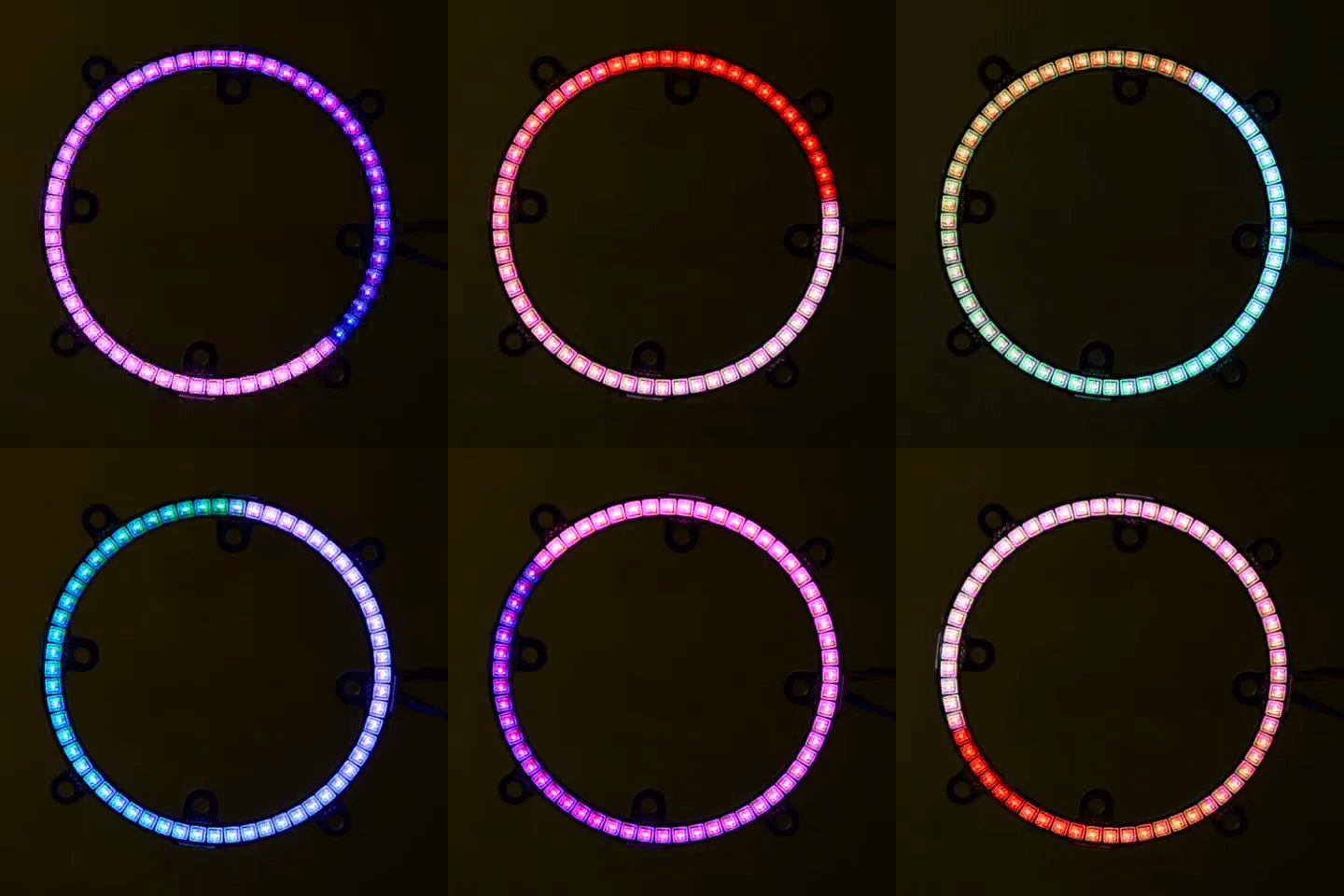
}

Your code should look like the GIF below if you’ve hooked everything up right. If thing’s aren’t quite what you’d expect, double check your wiring.

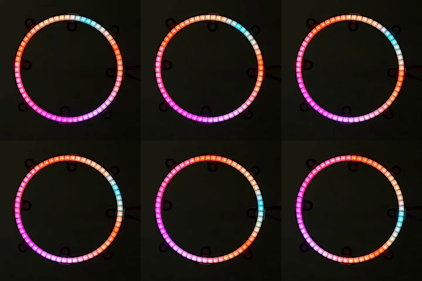
Example 1 Output

Example 1 Output

Example 2 — RGB Color Picker

In this second example, we’ll use the serial terminal to control the color displayed by the ring. We initialize everything in the same way. We then listen for data on the serial port, parsing integers that are sent from the serial terminal on your desktop and putting them in the corresponding color (red, green or blue). The code to accomplish this is shown below.

language:c
#include <FastLED.h>

// How many leds in your strip?
#define NUM_LEDS 60 //3 Inch
//#define NUM_LEDS 40 //2 Inch
//#define NUM_LEDS 20 //1 Inch

//Data and Clock Pins
#define DATA_PIN 16
#define CLOCK_PIN 17

CRGB color;
char colorToEdit;

// Define the array of leds
CRGB ring[NUM_LEDS];

void setup() {
  Serial.begin(115200);
  Serial.println("resetting");
  LEDS.addLeds<APA102, DATA_PIN, CLOCK_PIN, BGR>(ring, NUM_LEDS);
  LEDS.setBrightness(32);

  //Display our current color data
  Serial.print("Red Value: ");
  Serial.println(color[0]);
  Serial.print("Green Value: ");
  Serial.println(color[1]);
  Serial.print("Blue Value: ");
  Serial.println(color[2]);
  Serial.println();      
}

void loop()
{
  if (Serial.available()) //Check to see if we have new Serial data.
  {
    colorToEdit = Serial.read();
    switch (colorToEdit)
    {
      case 'R':
      case 'r':
        color[0] = Serial.parseInt();
        break;
      case 'G':
      case 'g':
        color[1] = Serial.parseInt();
        break;
      case 'B':
      case 'b':
        color[2] = Serial.parseInt();
        break;
    }
    //Display our current color data
    Serial.print("Red Value: ");
    Serial.println(color[0]);
    Serial.print("Green Value: ");
    Serial.println(color[1]);
    Serial.print("Blue Value: ");
    Serial.println(color[2]);
    Serial.println();
    for (int i = 0; i < NUM_LEDS; i++)
    {
      ring[i] = color;
      FastLED.show();
      delay(10);
    }
  }
}

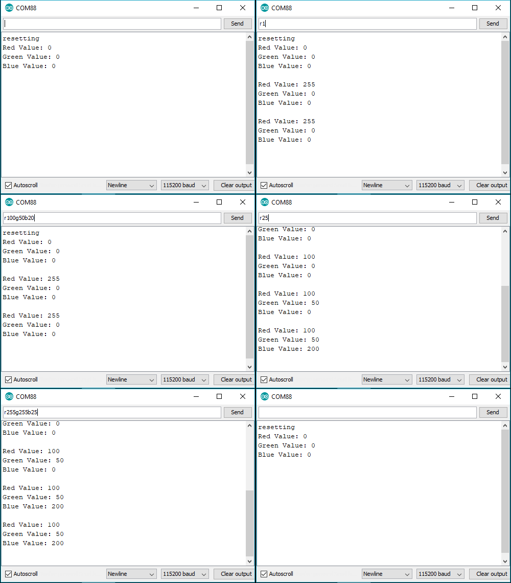
Go ahead and upload this code, then open your serial monitor to 115200. It should be displaying the current color value (R:0, G:0, B:0), if not.

RGB Color Picker

Changing the value of a color is done be sending the letter of the color (R, G, or B) followed by a value between 0 and 255. For instance, turning red to half brightness would be achieved by sending R127. Play around and look for your favorite color.

Example 3 — HSV Color Picker

The third example is very similar to the first in that we are picking colors using the serial terminal. However, in this example, we are working with an HSV color space. This sketch works mostly the same as the previous one, only we send h, s or v instead of r, g or b. Upload the below code and play around in search of your favorite color.

language:c
#include <FastLED.h>

// How many leds in your strip?
#define NUM_LEDS 60 //3 Inch
//#define NUM_LEDS 40 //2 Inch
//#define NUM_LEDS 20 //1 Inch

//Data and Clock Pins
#define DATA_PIN 16
#define CLOCK_PIN 17

CHSV color = CHSV(0, 255, 255);
char colorToEdit;

// Define the array of leds
CRGB ring[NUM_LEDS];

void setup() {
  Serial.begin(115200);
  Serial.println("resetting");
  LEDS.addLeds<APA102, DATA_PIN, CLOCK_PIN, BGR>(ring, NUM_LEDS);
  LEDS.setBrightness(32);

  //Display our current color data
  Serial.print("Hue: ");
  Serial.println(color.hue);
  Serial.print("Saturation: ");
  Serial.println(color.sat);
  Serial.print("Value: ");
  Serial.println(color.val);
  Serial.println();
}

void loop()
{
  if (Serial.available()) //Check to see if we have new Serial data.
  {
    colorToEdit = Serial.read();
    switch (colorToEdit)
    {
      case 'H':
      case 'h':
        color.hue = Serial.parseInt();
        break;
      case 'S':
      case 's':
        color.sat = Serial.parseInt();
        break;
      case 'V':
      case 'v':
        color.val = Serial.parseInt();
        break;
    }
    //Display our current color data
    Serial.print("Hue: ");
    Serial.println(color.hue);
    Serial.print("Saturation: ");
    Serial.println(color.sat);
    Serial.print("Value: ");
    Serial.println(color.val);
    Serial.println();

    for (int i = 0; i < NUM_LEDS; i++)
    {
      ring[i] = color;
      FastLED.show();
      delay(10);
    }
  }
}

Once again, play around to try and find your favorite color. I find that HSV is a much more intuitive space to work in than RGB space.

Example 4 — Angle Assignment

In this example, we’ll assign the LED’s in our circle to the angles of the unit circle so we won’t have to think about which LED corresponds to which angle. We’re also going to use 0-255 instead of 0-360, as this makes more sense from a computer standpoint. For example, the LED’s at 90° would be accessed by calling ringMap[64]. This is accomplished using the populateMap() function, which populates the uint8_t ringMap[255] object. The populateMap() function is shown below and gets called in our setup() loop.

language:c
#include <FastLED.h>

// How many leds in your strip?
#define NUM_LEDS 60 //3 Inch
//#define NUM_LEDS 40 //2 Inch
//#define NUM_LEDS 20 //1 Inch

//Data and Clock Pins
#define DATA_PIN 16
#define CLOCK_PIN 17

// Define the array of leds
CRGB ring[NUM_LEDS];
uint8_t ringMap[255];
uint8_t rotation = 0;

float angleRangePerLED = 256.0 / NUM_LEDS; //A single LED will take up a space this many degrees wide.

void populateMap () //we map LED's to a 360 degree circle where 360 == 255
{
  for (int ledNum = 0; ledNum < NUM_LEDS; ledNum++) //Loops through each LED and assigns it to it's range of angles
  {
    for (int j = round(ledNum * angleRangePerLED); j < round((ledNum + 1) * angleRangePerLED); j++)
    {
      ringMap[j] = ledNum;
    }
  }
}

void fadeAll(uint8_t scale = 250)
{
  for (int i = 0; i < NUM_LEDS; i++)
  {
    ring[i].nscale8(scale);
  }
}

void setup()
{
  Serial.begin(115200);
  FastLED.addLeds<APA102, DATA_PIN, CLOCK_PIN, BGR>(ring, NUM_LEDS);
  FastLED.setBrightness(32);
  populateMap();
}

In our loop, we’ll map each angle of the circle to a hue, then we’ll light up 3 pixels, each separated by 120° We do this by lighting an LED at a starting angle 0, then add 120° which corresponds to 85.333 ((120/360)*255 = 85.333) and light the LED at this angle. We repeat the same process to light the final LED. Each angle is matched to a hue, so we should see the same colors in each position.

language:c
void loop()
{
  for (int i = 0; i < 3; i++)
  {
    uint8_t angle = round(i * 85.3333) + rotation;
    ring[ringMap[angle]] = CHSV(angle, 127, 255);
  }
  FastLED.show();
  rotation++;
  fadeAll(248);
  delay(5);
}

Notice how ringMap[angle] is called within ring, as it will return the LED number at that angle. Uploading this code should look similar to the below GIF

Example 4 Output

Example 4 Output

Example 5 — Using Gradients

In this final example, we’ll leverage FastLED’s palette object (CRGBPalette16) to create and visualize a color palette on our ring. We have much the same initialization as our previous examples, only this time we also initialize a CRGBPalette16 object which will be full of colors along with a TBlendType which will tell us whether or not to blend the colors together or not. This can be either LINEARBLEND or NOBLEND. To populate this gradient, we use examples 2 and 3 to find the colors we want to put into our gradient. The gradient included is a bunch of colors created in HSV space, but you can easily change to RGB space if you prefer. You can also use any of the preset palettes by uncommenting the line that sets it equal to currentPalette.

language:c
TBlendType    currentBlending = LINEARBLEND;
CRGBPalette16 currentPalette = {
  CHSV(5, 190, 255),
  CHSV(0, 190, 255),
  CHSV(245, 255, 255),
  CHSV(235, 235, 255),
  CHSV(225, 235, 255),
  CHSV(225, 150, 255),
  CHSV(16, 150, 255),
  CHSV(16, 200, 255),
  CHSV(16, 225, 255),
  CHSV(0, 255, 255),
  CHSV(72, 200, 255),
  CHSV(115, 225, 255),
  CHSV(40, 255, 255),
  CHSV(35, 255, 255),
  CHSV(10, 235, 255),
  CHSV(5, 235, 255)
};

//currentPalette = RainbowColors_p;
//currentPalette = RainbowStripeColors_p;
//currentPalette = OceanColors_p;
//currentPalette = CloudColors_p;
//currentPalette = LavaColors_p;
//currentPalette = ForestColors_;
//currentPalette = PartyColors_p;

We then use the ColorFromPalette function to put the colors from our gradient onto our LED ring. Notice how we use the angle functions once again to map each part of the gradient to an angle.

language:c
void loop() {
  for (uint8_t i = 0; i < 255; i++)
  {
    uint8_t gradientIndex = i + rotation;
    ring[ringMap[i]] = ColorFromPalette(currentPalette, gradientIndex, brightness, currentBlending);
  }
  FastLED.show();
  rotation++;
  delay(20);
}

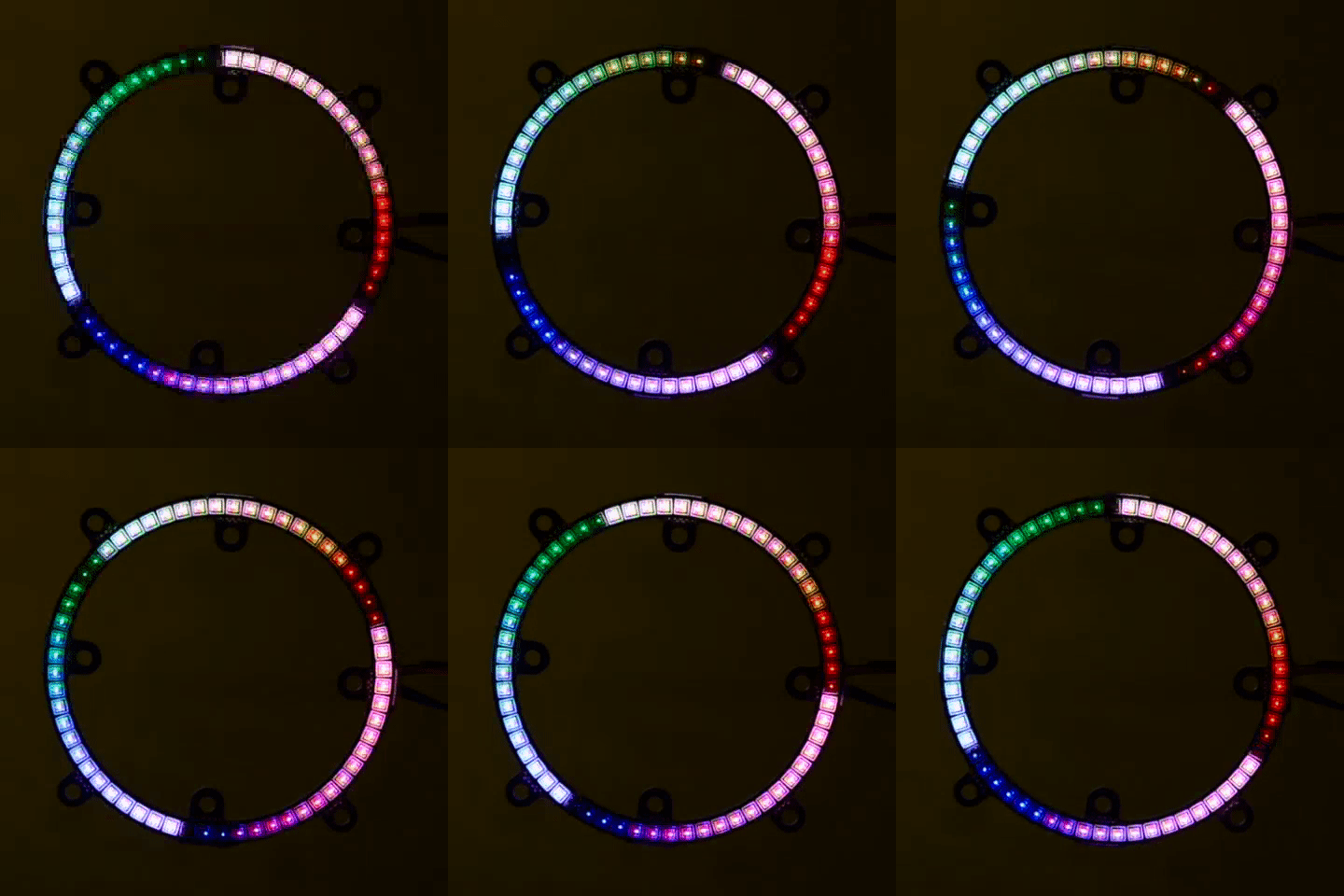
Play around with the colors in your palette until you’re satisfied. If all is hooked up correctly your ring should look something like the below GIF.

Example 5 Output

Example 5 Output

Additional Examples

There are quite a few additional examples contained in the FastLED library. While they aren’t made specifically for the rings, they can still show you some useful features in the FastLED library, and may give you some ideas for some animations of your own.

GitHub: FastLED > Examples

If the FastLED library is installed, they can be found from the Arduino IDE menu by opening up File ->Examples ->Examples From Custom Libraries ->FastLED .

Resources & Going Further

Now that you’ve successfully got your LuMini Ring up and running, it’s time to incorporate it into your own project! For more information about the LuMini Ring, check out the links below.

Lumini Ring 3 Inch

Lumini Ring 2 Inch

Lumini Ring 1 Inch


Looking for a different way of controlling the LuMini Rings? Check out the LuMini Drive to program the APA102's in Circuit Python.

Need some inspiration for your next project? Check out some of these related tutorials:

Let It Glow Holiday Cards

Craft a glowing card for friends and family this holiday season with paper circuits - no soldering required!

Hackers in Residence: The Sound Visualizer Pt. 2

An addition to a previous project, this time using a PC and a custom Java app to create your own music visualizer using a RGB LED matrix.

Light Up Silk Flower Corsage

Combine a silk flower with a built-in RGB LED and some LilyPad Switches to create a customizable accessory.

Spectral Triad (AS7265x) Hookup Guide

Learn how to wield the power of 18 channels of UV to NIR spectroscopy with AS72651 (UV), AS72652 (VIS), and AS72653 (NIR) sensors!

learn.sparkfun.com | CC BY-SA 3.0 | SparkFun Electronics | Niwot, Colorado

LumiDrive Hookup Guide

$
0
0

LumiDrive Hookup Guide a learn.sparkfun.com tutorial

Available online at: http://sfe.io/t855

Introduction

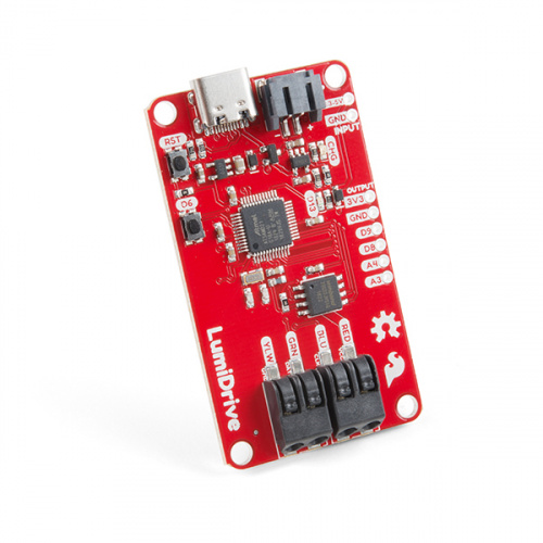
LumiDrive is SparkFun’s foray into all things Python on microcontrollers. Leveraging Adafruit’s Circuit Python, we have created a product made for driving a strand of APA102’s. We’ve broken out a few analog and digital pins from the onboard SAMD21G-AU microcontroller so that you can implement external buttons, switches, and other whizzbangs to interact with the LEDs.

SparkFun LumiDrive LED Driver

SparkFun LumiDrive LED Driver

DEV-14779
$19.95

Circuit Python

You can read the extensive documentation about Circuit Python here on Adafruit’s website, but let’s review a short and sweet version. Circuit Python is Adafruit’s version of MicroPython. What pray tell, is MicroPython? MicroPython is Python 3 for microcontrollers. MicroPython takes the power of the wildly popular Python interpreted language that is easy to use, easy to read, and powerful and makes it usable for microcontrollers. It feels familiar in the way you declare and use pins but unlike Arduino, you don’t have to compile or upload your code. This is because your microcontroller acts like a USB drive when you plug it into your computer. The code simply lives as a file that you modify directly and when it’s saved, it is automatically loaded. Algebraic! It’s also compatible with the Python 3 you have on your computer so that you can develop seamlessly on your desktop! Why are we using Circuit Python? Circuit Python has the advantage of having many libraries built in by default that are catered toward entry-level hobbyists. In the case of the LumiDrive, we’ll be utilizing the DotStar library, Adafruit’s library for APA102 LEDs.

Required Materials:

LED RGB Strip - Addressable, 1m (APA102)

LED RGB Strip - Addressable, 1m (APA102)

COM-14015
$15.95
2
USB 3.1 Cable A to C - 3 Foot

USB 3.1 Cable A to C - 3 Foot

CAB-14743
$4.95
2

We have many portable options to power your LEDs:

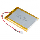
Lithium Ion Battery - 1Ah

Lithium Ion Battery - 1Ah

PRT-13813
$9.95
7
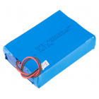
Lithium Ion Battery - 2Ah

Lithium Ion Battery - 2Ah

PRT-13855
$12.95
4
Lithium Ion Battery - 6Ah

Lithium Ion Battery - 6Ah

PRT-13856
$29.95
5

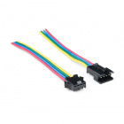
I found this connector to be very helpful because it kept me from plugging and unplugging different strands of APA102’s directly into the poke-home connectors.

LED Strip Pigtail Connector (4-pin)

LED Strip Pigtail Connector (4-pin)

CAB-14576
$1.50

Suggested Reading

Battery Technologies

The basics behind the batteries used in portable electronic devices: LiPo, NiMH, coin cells, and alkaline.

Light-Emitting Diodes (LEDs)

Learn the basics about LEDs as well as some more advanced topics to help you calculate requirements for projects containing many LEDs.

Mean Well LED Switching Power Supply Hookup Guide

In this tutorial, we will be connecting a Mean Well LED switching power supply to an addressable LED strip controlled by an Arduino.
New!

LuMini Ring Hookup Guide

The LuMini Rings (APA102-2020) are the highest resolution LED rings available.

Hardware Overview

Power

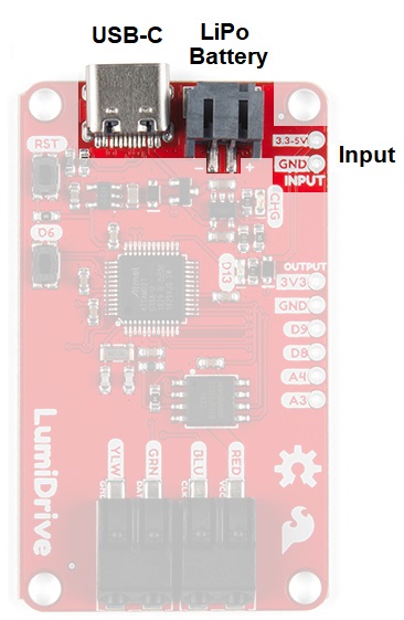
There are three options for power on the product: USB-C, Lithium Ion Battery, or Input. You can provide power in the range from 3.3V-6V.

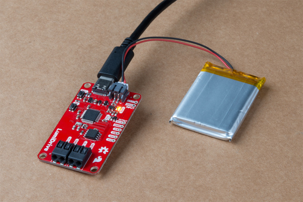
This picture highlights the power input of the board that includes the USB-C connector, Lipo Connector, and two pin header just next to the lipo connector.

USB-C

USB-C, aside from being reversible which is already awesome, has the capability of supplying more power than its predecessor. I was able to pull 2 AMPs from my computer on a 3.1 USB plug. Be cautious - I did this so that you don’t have to! Every computer is different and I strongly advise that you don’t do something so rash unless you are absolutely confident. Also keep in mind that different USB ports (2.0, 3.0, and 3.1) supply different levels of power. 3.1 is easy to identify because it has a blue tongue when you look into the port.

Lithium Ion Battery

We have many options in our catalog that will suit your various portable power needs. LumiDrive also comes with a charging circuit so you can charge your LiPo battery.

LiPo Battery Plugged in as well as USB-C Power

Two Pin Input Headers

Last but not least is a 2 pin header labeled INPUT where you can supply your own power.

Current Draw

The table below lists the current draw for a strand of 55 LEDs at full white at half and full brightness. I’ve also included current draw for the various included functions at varying LED amounts and brightness to help you make more educated decisions when purchasing or using your LEDs.

# of LEDs (Half Brightness) Current Consumption (Amps)
1 0.070
2 0.095
3 0.120
5 0.139
10 0.289
20 0.536
30 0.755
35 0.883
40 1.102
50 1.311
# of LEDs (Full Brightness) Current Consumption (Amps)
10 0.520
15 0.737
25 1.328
27 1.426
29 1.523
31 1.618
40 2.018
Function at 55 LEDs Current Consumption (Amps)
Slice Rainbow (0.25 Brightness) 0.336
Slice Rainbow (0.50 Brightness) 0.600
Rainbow Cycle (0.25 Brightness) 0.281
Rainbow Cycle (0.50 Brightness) 0.500
Function at 85 LEDs Current Consumption (Amps)
Slice Rainbow (0.25 Brightness) 0.500
Slice Rainbow (0.50 Brightness) 0.890
Rainbow Cycle (0.25 Brightness) 0.425
Rainbow Cycle (0.50 Brightness) 0.727

Input Output

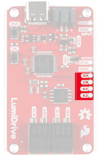
There are four input/output pins broken out to the side of the product. There are two digital pins and two analog pins. These can be used to interact with your LED strand (or not) by attaching buttons, switches, light sensors, etc.

This picture shows the top side of the product with the usb-c connector facing up, highlighting the four lowest plated through holes as input and output pins.

Buttons

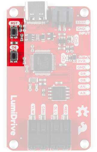
There are two buttons on the product. The top button is a reset button which will reset the board on press. The second is a button attached to digital pin D6. You can use this in place of attaching a button to the board.

This picture shows the topside of the product with the USB-C connector facing up, and highlights the two buttons on the left side. The top being reset and the other D6.

LEDs

There are two LEDs on board. The top LED in the picture is a yellow charge LED that indicates that a LiPo battery is being charged. The second is a blue stat LED attached to pin D13.

This picture shows the topside of the product with the USB-C connector facing up, and highlights the two LEDs on the right side, one labeled Charge and the other LED.

Poke-home Connectors

There are two Poke-home connectors at the bottom of the product.

This picture shows the topside of the product with the USB-C connector facing up, and highlights the two large side by side Poke-home connectors that allow for easily connecting of wires without soldering.

They are versatile and rather robust and allow you to plug in wire without the need for solder. They’re labeled with the color of wire that is used in the strands of APA102 LEDs that we sell here at SparkFun but are not limited to just those. Just below that silk you’ll notice the function of those lines are labeled as in the following chart.

PinDescription
REDVCC (3.3-5V)
BLUClock
GRNData
YELLOWGround

Hardware Assembly

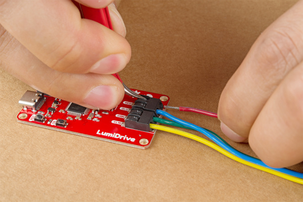
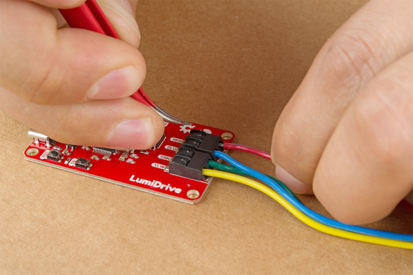
Hardware assembly is straight forward. Let’s start by plugging your LED strand into the poke-home connectors. Finer control can be achieved by using a pair of tweezers to press in the flap on the topside of the poke-home connector.

Inserting the wire into the poke home clamp with the black flap pressed down by tweezers

When you press onto the black flap on the top of the poke-home connector, two metal wedges move laterally - to the sides of the product- inside the connector. Push your wire into the poke-home connector. When you release it, the two wedges will clamp down onto the wire. Give them a slight tug to make sure the wires are in there solid. You’re ready to rock!

Wire inserted into poke home clamp and black flap no longer depressed

Plug your LumiDrive into your computer with the USB-C connector. It should pop up automatically as a hard drive called CIRCUITPY. If it doesn’t pop up automatically, unplug it and plug it back in. If that doesn’t work, navigate to your files folder and look for CIRCUITPY on the left hand side and give it a click. At this point the blue stat LED on the LumiDrive should be blinking. From here you can open up that CIRCUITPY by clicking on it.

Drag and drop folder view

Having a hard time seeing? Click the image for a closer look.

Note! You may or may not be wondering what all these files are on the CIRCUITPY drive? I have hidden files turn on, on my computer. Files with preceding periods i.e. ".Trashes" or ".metadata_never_index" are necessary for MAC users.The boot_out.txt file tells you what version of Circuit Python is loaded onto your LumiDrive. Finally "Main.py" is where all the fun happens.

Let’s move onto the example code.

Example Code

Your LumiDrive should already come with the following code but in case something happens to it, than you can re-download the code here:

LumiDrive Main.py Example Code

Before we begin, let’s talk about the options for loading and updating this code on your LumiDrive. One option is to move the file main.py, onto your desktop and edit it with a text editor. When you’re done with it, you can simply drag and drop it back into the CIRCUITPY drive. Circuit Python will recognize the change and automatically load the new code. The other option is to edit the file directly in the CIRCUITPY drive. This option is much more convenient and efficient, but requires a text editor that writes the file completely when it’s saved. On Windows not all text editors exhibit the necessary behavior. Below is a list of good, not great, and not recommended text editors for editing files directly on LumiDrive (or any Circuit Python board). If you’re using a Mac then you won’t be running into any of these issues.

GOODGOOD only with ADD-ONSNOT Recommended
MUPYCharm IDENotepad/Notepad++
VIMAtomIDLE
EMACSSlick EditNano
Sublime Text
Visual Studio Code

My suggestion would be to use MU or Sublime Text. The first is more beginner friendly while the second is more light weight with some really nice features. If you’re already familiar with VIM, EMACS, or Visual Studio Code then use those instead.

If you’re attached to one of the not recommended editors then there is a way to get it to work. After you’ve made changes to the main.py, if you eject the CIRCUITPY drive then it will force Windows to write the saves that you made.

Let’s quickly talk about which files Circuit Python monitors for saves. Circuit Python looks for the following four files in this order and runs the first one it finds: code.txt, code.py, main.txt, and main.py. That’s all of it, now onto the code.

At the top of the code we have a number of libraries that are necessary for our code.

language:python
import adafruit_dotstar # Our LED library
import digitalio
import board
import math
import time

Here’s where you can start to modify the code to your particular LED strip. The num_pixels variable should reflect how many LEDs you have and brightness controls the brightness. We have 60 pixels in the example because it reflects the number of LEDs of our 1m length of APA102s. Keep in mind as you set these that if you’re powering through your computer, don’t add too many too quickly. Otherwise you could potentially harm your computer. Below our two variables we create an instance of our library called pixels, and just below that we have some pre-defined colors.

language:python
# These two variables should be adjusted to reflect the number of LEDs you have
# and how bright you want them.
num_pixels = 60 
brightness = 0.25

# This creates the instance of the DoTStar library. 
pixels = adafruit_dotstar.DotStar(board.SCK, board.MOSI, 
    num_pixels, brightness=brightness, auto_write=False)

# Some standard colors. 
BLACK = (0, 0, 0)
RED = (255, 0, 0)
YELLOW = (255, 150, 0)
ORANGE = (255, 40, 0)
GREEN = (0, 255, 0)
TEAL = (0, 255, 120)
CYAN = (0, 255, 255)
BLUE = (0, 0, 255)
PURPLE = (180, 0, 255)
MAGENTA = (255, 0, 20)
WHITE = (255, 255, 255)

# A list of the ten colors. Use this if you want to cycle through the colors. 
colorList = [RED, YELLOW, ORANGE, GREEN, TEAL, CYAN, BLUE, PURPLE, MAGENTA,
                    WHITE]

We have a number of functions to handle different LED behaviors. Each function has a little explanation commented just above it’s definition.

language:python
# The travel function takes a color and the time between updating the color. It
# will start at LED one on the strand and fill it with the give color until it
# reaches the maximum number of pixels that are defined as "num_pixels".
def travel(color, wait):
    num_pixels = len(pixels)
    for pos in range(num_pixels):
        pixels[pos] = color 
        pixels.show() 
        time.sleep(wait)

# The travel_back function like the travel function takes a color and the time between 
# updating the color. However it unlike the travel function, it will start at
# the last LED and works its way to LED. Fill the LED with the given color.
def travel_back(color, wait):
    num_pixels = len(pixels)
    for pos in range(num_pixels, 0, -1):
        pixels[pos] = color 
        pixels.show() 
        time.sleep(wait)

# This function may give you an idea of other functions to create. Here we're
# starting with green LEDs and then slowing filling the red color until we have
# a yellow color.  
def green_yellow_wheel(wait):
    for redColor in range(255):
        color = (redColor, 150, 0)
        pixels.fill(color)
        pixels.show()
        time.sleep(wait)

# You can use this function to get a custom color value. 
# value much in the form of a tuple, like the colors above. 
def wheel(pos):
    # Input a value 0 to 255 to get a color value.
    # The colours are a transition r - g - b - back to r.
    if pos < 0 or pos > 255:
        return (0, 0, 0)
    if pos < 85:
        return (255 - pos * 3, pos * 3, 0)
    if pos < 170:
        pos -= 85
        return (0, 255 - pos * 3, pos * 3)
    pos -= 170
    return (pos * 3, 0, 255 - pos * 3)

# This function takes a color and a dely and fills the entire strand with that color. 
# The delay is given in the case you use multiple color fills in a row.  
def color_fill(color, wait):
    pixels.fill(color)
    pixels.show()
    time.sleep(wait)

# Fills the strand with two alternating colors and cycles through the 10 colors 
def slice_alternating(wait):

    num_pixels = len(pixels)

    pixels[::2] = [RED] * (num_pixels // 2)
    pixels.show()
    time.sleep(wait)
    pixels[1::2] = [ORANGE] * (num_pixels // 2)
    pixels.show()
    time.sleep(wait)
    pixels[::2] = [YELLOW] * (num_pixels // 2)
    pixels.show()
    time.sleep(wait)
    pixels[1::2] = [GREEN] * (num_pixels // 2)
    pixels.show()
    time.sleep(wait)
    pixels[::2] = [TEAL] * (num_pixels // 2)
    pixels.show()
    time.sleep(wait)
    pixels[1::2] = [CYAN] * (num_pixels // 2)
    pixels.show()
    time.sleep(wait)
    pixels[::2] = [BLUE] * (num_pixels // 2)
    pixels.show()
    time.sleep(wait)
    pixels[1::2] = [PURPLE] * (num_pixels // 2)
    pixels.show()
    time.sleep(wait)
    pixels[::2] = [MAGENTA] * (num_pixels // 2)
    pixels.show()
    time.sleep(wait)
    pixels[1::2] = [WHITE] * (num_pixels // 2)
    pixels.show()
    time.sleep(wait)


# This function divides the given number of pixels and fills them as evenly as
# possible with a rainbow pattern (RED, ORANGE, YELLOW, GREEN, BLUE, PURPLE) 
# which repeats every 6 LEDs.
def slice_rainbow(wait):

    num_pixels = len(pixels)

    pixels[::6] = [RED] * math.ceil(num_pixels / 6)
    pixels.show()
    time.sleep(wait)
    pixels[1::6] = [ORANGE] * math.ceil((num_pixels - 1) / 6)
    pixels.show()
    time.sleep(wait)
    pixels[2::6] = [YELLOW] * math.ceil((num_pixels -2) / 6)
    pixels.show()
    time.sleep(wait)
    pixels[3::6] = [GREEN] * math.ceil((num_pixels-3) / 6)
    pixels.show()
    time.sleep(wait)
    pixels[4::6] = [BLUE] * math.ceil((num_pixels-4) / 6)
    pixels.show()
    time.sleep(wait)
    pixels[5::6] = [PURPLE] * math.ceil((num_pixels-5) / 6)
    pixels.show()
    time.sleep(wait)


# This function makes a strand of LEDs look like a rainbow flag that travels
# along the length of the strand. It is not infinitely contniuous and will stop
# after any single LED has cycled through every color.  
def rainbow_cycle(wait):
    num_pixels = len(pixels)
    for j in range(255):
        for i in range(num_pixels):
            rc_index = (i * 256 // num_pixels) + j
            pixels[i] = wheel(rc_index & 255)
        pixels.show()
        time.sleep(wait)

print("Clearing LEDs.")
color_fill(BLACK,0) 

Finally we have a while loop that is akin to void loop in Arduino. Right now we have the loop blinking our blue D13 stat LED.

language:python
#Ah trusty ol' blink. 
while True: 
    led.value = True
    time.sleep(.5)
    led.value = False
    time.sleep(.5)

Instead, let’s pick some functions from the functions above and type them in. I chose the following and gave the function its' necessary parameter: a delay time.

language:python
while True: 
    rainbow_cycle(0)

After you’ve modified the code, just hit save (assuming you have the correct text editor for saving directly on LumiDrive) and the code will automatically run. If all is well you should see the following:

LED strand example in the dark

Algebraic!

Using the 3 inch LuMini ring, and a couple other functions.

LumiDrive Demo with Lumini Ring

Heads up! Updating the APA102s gets slower the longer the strand or the amount of LEDs you're driving. There's also some known efficiency issues with the DotStar library.

Read-Evaluate-Print-Loop (REPL)

A note about the Read-Evaluate-Print-Loop, or the REPL. It’s a language shell that allows you to interact with the LumiDrive in an Interactive Python environment. If you pull up your favorite serial program and open it to the COM port of the LumiDrive you should see the following.

Terminal Window showing REPL

Having a hard time seeing? Click the image for a closer look.

Main.py will be running an infinite blink loop fresh out of the box. Simply press CTRL-C to interrupt the code. Here you have an interactive python environment to play around in.! Here we can do some fun things like Math!

Terminal window showing math example

Having a hard time seeing? Click the image for a closer look.

More importantly we can see what libraries and pins are available to us in the version of Circuit Python that is loaded on your LumiDrive, using the help(modules) and dir(board) commands respectively.

Terminal window showing  help modules and dir(board)

Having a hard time seeing? Click the image for a closer look.

If you look at the line that says dir(board), just below are various pins that are available in Circuit Python but not all of them are physically broken out on the board. When you’re done messing around in REPL and ready to run the code that is on your LumiDrive, you can press CTRL-D and that will initiate a soft reboot.

Resources and Going Further

Need more inspiration? Check out some of these tutorials:

Simon Says Experiments

So you've built up a Simon Says kit? What next? This tutorial will get you up and running with Arduino software, guide you through a few example sketches, and send you on your way to create your own. Careful, this stuff is highly addictive. :)

Marquee Party Bag

This tutorial provides everything you need to know to make your own Marquee Party Bag!

Addressable LED Neon Flex Rope Hookup Guide

The addressable (UCS1903) LED neon flex rope adds cool lighting effects for outdoor and indoor uses including in hallways and stairs, holiday lighting, and more! In this hookup guide, you will learn how to connect, power, and control the LED segments with an Arduino and the FastLED library.

Gator:starter ProtoSnap Hookup Guide

Get started clipping sensors and lights to the micro:bit with the gator:starter gator:board from SparkFun!

learn.sparkfun.com | CC BY-SA 3.0 | SparkFun Electronics | Niwot, Colorado

Wireless Remote Control with micro:bit

$
0
0

Wireless Remote Control with micro:bit a learn.sparkfun.com tutorial

Available online at: http://sfe.io/t850

Introduction

In this tutorial, we will utilize MakeCode's radio blocks to have one micro:bit transmit a signal to a receiving micro:bit on the same channel. Eventually, we will control a micro:bot wirelessly using parts from the micro:arcade kit!

Wireless Remote Control with micro:bit

Required Materials

To follow along with this tutorial, you will need the following materials at a minimum. You may not need everything though depending on what you have. Add it to your cart, read through the guide, and adjust the cart as necessary.

You Will Also Need

The following materials are optional to make a battle bot.

  • Scissors
  • Electrical Tape or Glue
  • Ping Pong Ball
  • Skewers

Suggested Reading

If you aren’t familiar with the following concepts, we recommend checking out these tutorials before continuing.

Getting Started with the micro:bit

The BBC micro:bit is a compact, powerful programming tool that requires no software installation. Read on to learn how to use it YOUR way!

micro:bot Kit Experiment Guide

Get started with the moto:bit, a carrier board for the micro:bit that allows you to control motors, and create your own robot using this experiment guide for the micro:bot kit.

micro:arcade Kit Experiment Guide

We love games! We love writing games, building games and yes, even building game consoles. So we want to introduce to you the micro:arcade kit for the micro:bit!

Installing the Extensions for Microsoft MakeCode

To make the most out of the carrier boards with the least amount of coding, use the Microsoft MakeCode extensions written for the gamer:bit and moto:bit boards. If you have not already, check out the instructions for installing the extensions for both boards as explained in their respective guides whenever you make a new MakeCode project utilizing the boards.

SparkFun Extensions

gamer:bit Extension

To install the extension for the gamer:bit, head over to our micro:arcade kit experiment guide to follow the instructions.

Installing the gamer:bit Extension for Microsoft MakeCode

moto:bit Extension

To install the extension for the moto:bit, head over to our micro:bot kit experiment guide to follow the instructions.

Installing the moto:bit Extension for Microsoft MakeCode

Experiment 1: Sending and Receiving a Signal

Introduction

There are a few methods of transmitting data between two or more micro:bits. You can send a number, value, or a string. For simplicity, we will send one number between two micro:bits.

Parts Needed

You will need the following parts:

  • 2x micro:bit Boards
  • 2x Micro-B USB Cables

For a few items listed, you will need more than one unit (i.e. micro:bits, micro-B USB cables, etc.). You may not need everything though depending on what you have. Add it to your cart, read through the guide, and adjust the cart as necessary.

micro:bit Board

micro:bit Board

DEV-14208
$14.95
5
USB Micro-B Cable - 6"

USB Micro-B Cable - 6"

CAB-13244
$1.95
3

1.1: Sending

For this part of the experiment, we are going to send a number from one micro:bit to another micro:bit on the same channel.

Hardware Hookup

Connect the first micro:bit to your computer via USB cable.

micro-B USB Cable Inserted into Micro:bit

Running Your Script

We are going to use Microsoft MakeCode to program the micro:bit. You can download the following example script and move the *.hex file to your micro:bit. Or use it as an example to build it from scratch in MakeCode.


Note: You may need to disable your ad/pop blocker to interact with the MakeCode programming environment and simulated circuit!

Code to Note

When the micro:bit is powered up, we’ll want it set up the radio to a certain channel. In this case, we head to the Radio blocks, grab the radio set group &lowbar;&lowbar; block, and set it to 1. We will use the built-in button A on the micro:bit. From the Input blocks, we use the on button A pressed, Once the button is pressed, we will transmit a number 0 wirelessly. For feedback, we will use the Basic blocks to have the LEDs animate with a dot expanding out into a square to represent a signal being sent out. Once the animation is finished, we will clear the screen.

MakeCode Sending Number Example

Having a hard time seeing the code? Click the image for a closer look.


1.2: Receiving

For this part of the experiment, we are going to have a second micro:bit receive a number from the first micro:bit.

Hardware Hookup

To avoid confusion when uploading code, unplug the first micro:bit from your computer. Then connect the second micro:bit to your computer via USB cable.

Insert Second micro:bit

Running Your Script

Download the following example script and move the *.hex file to your micro:bit. Or use it as an example to build it from scratch in MakeCode. You will need to open a new project to receive the data from the first part of this experiment.


Note: You may need to disable your ad/pop blocker to interact with the MakeCode programming environment and simulated circuit!

Code to Note

When the second micro:bit is powered up, we’ll want to set the radio to the same channel as the first micro:bit. In this case, it will be 1. Using the on radio received &lowbar;&lowbar;&lowbar;&lowbar;&lowbar;&lowbar;&lowbar;&lowbar;&lowbar;&lowbar; block, we will want to check to see what signal was received. In this case, we will want to check for a receivedNumber that is equal to 0 since a number was sent from the first micro:bit. Using the if statement from the Logic blocks, we will want to check if the variable holding the received number matches 0. If it matches, we will want the micro:bit to do something. Visually, using LEDs would be the easiest so an animation of a square shrinking to a dot was chosen to represent the received signal. Once the animation is finished, we will want to clear the screen until we receive another signal.

MakeCode Receiving Number Example

Having a hard time seeing the code? Click the image for a closer look.


What You Should See

Pressing on button A with the first micro:bit (our transmitting) will send a number out in channel 1. In this case, the number that is transmitted is 0.

The second micro:bit (our receiving) will take that number that was sent on channel 1 and do something based on the condition statement. In this case, there is an animation using the LED array to indicate when we have received the number.

Demo of micro:bit transmitting to another microbit


Experiment 2: Wirelessly Driving Forward

Introduction

Remember our micro:bot? The micro:bot was running around loose by itself the last time we were working with the robot. Let's give it some commands so that it only moves when you want it to using the gamer:bit carrier board!

Parts Needed

You will need the following parts:

  • 2x micro:bit Boards
  • 2x Micro-B USB Cables
  • 1x Assembled micro:bot Kit
  • 1x gamer:bit Carrier Board
  • 6x AA Batteries

For a few items listed, you will need more than one unit (i.e. micro:bits, AA batteries, etc.). You may not need everything though depending on what you have. Add it to your cart, read through the guide, and adjust the cart as necessary.

micro:bit Board

micro:bit Board

DEV-14208
$14.95
5
SparkFun micro:bot kit

SparkFun micro:bot kit

KIT-14216
$62.95
9
SparkFun micro:arcade kit

SparkFun micro:arcade kit

KIT-14218
$52.95
USB Micro-B Cable - 6"

USB Micro-B Cable - 6"

CAB-13244
$1.95
3
1500 mAh Alkaline Battery - AA

1500 mAh Alkaline Battery - AA

PRT-09100
$0.50

2.1 Remote Control

For this part of the experiment, we will use the same method as experiment 1 to transmit a command. As soon as a certain combination of buttons are pressed on the gamer:bit, the attached micro:bit will transmit one command to a receiving micro:bit. For debugging purposes, we are going to have a short animation when the buttons are pressed for feedback.

Hardware Hookup

If you have not already, insert one micro:bit into the gamer:bit’s carrier board. Make sure to insert the micro:bit with the LED array facing up (the same direction as all of the buttons) as explained in the micro:arcade kit experiment guide. We’re continuing on from experiment 3. Make sure to check out the guide before continuing on.

micro:arcade Kit Experiment Guide

July 21, 2017

We love games! We love writing games, building games and yes, even building game consoles. So we want to introduce to you the micro:arcade kit for the micro:bit!

Then connect the micro:bit to your computer via USB cable.

gamer:bit micro:bit and USB Cable

Running Your Script

Download the following example script and move the *.hex file to your micro:bit. Or use it as an example to build it from scratch in MakeCode. Remember, if you are building from scratch, you will need to install the appropriate extension when using the gamer:bit.


Note: You may need to disable your ad/pop blocker to interact with the MakeCode programming environment and simulated circuit!

Code to Note

When the micro:bit is powered up, we'll want it set up the radio to a certain channel. In this case, we set the radio block to 1 just like experiment 1. Then we’ll want to check if the P16 button is pressed on the gamer:bit, just like an accelerate button used in driving games. For simplicity, we will want the robot to move forward when pressing the up (P0) button on the direction pad. We will be using a nested if statement to check on the buttons defined in the gamer:bit extension. A nested if statement is one or more if statements “nested” inside of another if statement. If the parent if statement is true, then the code looks at each of the nested if statements and executes any that are true. If the parent if statement is false, then none of the nested statements will execute. By using the logic statement, we will be using the gamer:bit &lowbar;&lowbar;&lowbar;&lowbar; is pressed block.

Once both buttons are pressed, we will send a command out. In this case, it will be number 0. For feedback, to see if our code works as expected, we will have the LEDs animate with an arrow pointing up and a square growing bigger. We then give the micro:bit a short pause before clearing the screen and looping back to the beginning of the forever loop.

MakeCode Remote Control Example

Having a hard time seeing the code? Click the image for a closer look.


2.2 Robot Receive

In this part of the experiment, we need to have a receiving micro:bit recognize the command that was sent from the first micro:bit in order to control the micro:bot. For simplicity, we will have the robot drive forward. To debug, the LED array will display an arrow to indicate the direction where the robot should move for feedback.

Hardware Hookup

At this point, you should have your micro:bot kit assembled! We’re continuing on from experiment 5. Make sure to check out the guide before continuing on.

micro:bot Kit Experiment Guide

July 21, 2017

Get started with the moto:bit, a carrier board for the micro:bit that allows you to control motors, and create your own robot using this experiment guide for the micro:bot kit.

To avoid confusion when uploading code, unplug the first micro:bit from your computer. Connect the second micro:bit to your computer via USB cable.

Micro:bot Moto:bit Micro:Bit USB Cable

Running Your Script

Download the following example script and move the *.hex file to your micro:bit. You can also use it as an example to build it from scratch in MakeCode. Remember, if you are building from scratch, you will need to install the appropriate extension when using the moto:bit.


Note: You may need to disable your ad/pop blocker to interact with the MakeCode programming environment and simulated circuit!

Code to Note

When the second micro:bit is powered up, we'll want to set the radio to the same channel as the first micro:bit; again to 1. As explained in the micro:bot experiment guide, we will want to set the left and right motors' logic based on the way we connected the motors to the motor:bit. For consistency, we will make both true. Using the on radio received &lowbar;&lowbar;&lowbar;&lowbar;&lowbar;&lowbar;&lowbar;&lowbar;&lowbar;&lowbar; block from the moto:bit extension, we will want to check to see what command was received. In this case, it should be a 0 that was sent from the first micro:bit. If the command that was sent matches 0, we will want the moto:bit to drive forward at 100%. For feedback, we will have an arrow point up. After a short pause of about 50ms, we will want to clear the screen and turn the motors off before checking again. If the pause is too long, the micro:bot will continue to drive forward even after you remove your fingers from the gamer:bit's buttons.

MakeCode Receiving micro:bot Code

Having a hard time seeing the code? Click the image for a closer look.


What You Should See

Now that both micro:bits are programmed, let's the test code out. Disconnect the USB cables from both micro:bits and power each with the respective battery packs.

Inserting JST Connector into micro:bit2xAA Battery Pack INserted into JST Connector of micro:bit

For the micro:bot, insert the 4xAA battery pack into the barrel jack.

Barrel Jack Being Inserted into moto:bit4xAA Battery Pack Inserted into Barrel Jack of moto:bit

Then move the switch labeled as RUN MOTORS to the ON position. Pressing on the drive button (P16) and up button (P0) on the gamer:bit will cause the micro:bot to drive forward. You should also see the LED array animate.

Demo Test Wireless Control micro:bot with gamer:bit


Experiment 3: Wirelessly Controlling the micro:bot

Introduction

Now that we are able to wirelessly move our robot forward, we will want additional commands for turning and driving in reverse. While we are at it, we are going to give a special function to control the servos attached to our battle bot.

Parts Needed

You will need the following parts:

  • 2x micro:bit Boards
  • 2x Micro-B USB Cables
  • 1x Assembled micro:bot Kit
  • 1x gamer:bit Carrier Board
  • 6x AA Batteries

For a few items listed, you will need more than one unit (i.e. micro:bits, AA batteries, etc.). You may not need everything though depending on what you have. Add it to your cart, read through the guide, and adjust the cart as necessary.

micro:bit Board

micro:bit Board

DEV-14208
$14.95
5
SparkFun micro:bot kit

SparkFun micro:bot kit

KIT-14216
$62.95
9
SparkFun micro:arcade kit

SparkFun micro:arcade kit

KIT-14218
$52.95
USB Micro-B Cable - 6"

USB Micro-B Cable - 6"

CAB-13244
$1.95
3
1500 mAh Alkaline Battery - AA

1500 mAh Alkaline Battery - AA

PRT-09100
$0.50

3.1 Full Remote Control

For this part of the experiment, we will repeat the steps in 2.1 to transmit commands for turning or driving in reverse. The built-in accelerometer will be used to detect a shake. A command to control the servo motors will be sent out as soon as there is a shake detected.

Hardware Hookup

If you have not already, insert one micro:bit into the gamer:bit’s carrier board. Make sure to insert the micro:bit with the LED array facing up (the same direction as all of the buttons) as explained in the micro:arcade kit experiment guide. We’re continuing on from experiment 3. Make sure to check out the guide before continuing on.

micro:arcade Kit Experiment Guide

July 21, 2017

We love games! We love writing games, building games and yes, even building game consoles. So we want to introduce to you the micro:arcade kit for the micro:bit!

Disconnect the battery pack from micro:bit from the previous experiment. The JST connector is a tight fit in the micro:bit so you will need to carefully remove the connector out by wiggling it side to side using your index finger and thumb. It is easier to remove the micro:bit from the gamer:bit carrier board.

JST Connector Removed

Then connect the first micro:bit to your computer via USB cable.

gamer:bit micro:bit and USB Cable

Running Your Script

Download the following example script and move the *.hex file to your micro:bit. Or use it as an example to build it from scratch in MakeCode. You will need to open a new project to receive the data from the first part of this experiment. Remember, if you are building from scratch, you will need to install the appropriate extension when using the gamer:bit.


Note: You may need to disable your ad/pop blocker to interact with the MakeCode programming environment and simulated circuit!

Code to Note

Using the same template for driving forward, we assign a unique number to the right (P2), down (P8), and left (P1) buttons on the direction pad. For simplicity, we will just want the robot to move forward when turning right or left. There is not as much animation with the LED array in this example since it can slow down your micro:bit. Using the Input's on shake block from the Input, a unique number is sent out to control the servos. Again, an arrow will display briefly for feedback in each case.

MakeCode Remote Control

Having a hard time seeing the code? Click the image for a closer look.


3.2 Full Battle Bot Control

For this part of the experiment, we will repeat the steps in 2.2 to receive the commands before moving the robot. Instead of just driving forward, the robot can now turn, reverse, and control the servo motors.

Hardware Hookup

We’ll be using the same servo connection on the battle bot as explained in experiment 5. Make sure to check out the guide before continuing on.

micro:bot Kit Experiment Guide

July 21, 2017

Get started with the moto:bit, a carrier board for the micro:bit that allows you to control motors, and create your own robot using this experiment guide for the micro:bot kit.

Remove the battery pack from the moto:bit carrier board from the previous experiment.

Remove Barrel Jack

To avoid confusion when uploading code, unplug the first micro:bit from your computer. Then connect the second micro:bit to your computer via USB cable.

micro:bit moto:bit micro:bit and USB Cable

Running Your Script

Download the following example script and move the *.hex file to your micro:bit. Or use it as an example and build it from scratch in MakeCode. You will need to open a new project to receive the data from the first part of this experiment. Remember, if you are building from scratch, you will need to install the appropriate extension when using the moto:bit.


Note: You may need to disable your ad/pop blocker to interact with the MakeCode programming environment and simulated circuit!

Code to Note

We set up the second micro:bit to use the same channel and motor logic as explained in experiment 2.2. Four more commands were added to the on radio received &lowbar;&lowbar;&lowbar;&lowbar;&lowbar;&lowbar;&lowbar;&lowbar;&lowbar;&lowbar; to turn right, reverse, turn left, and control the servo motors of our battle bot. When turning, the motor closest to the inside of the turn is set to a lower value. That way the robot will continue to drive forward but also move right or left. To reverse, both motors used the reverse option to drive backwards. Finally, if the robot receives a command indicating that there was a shake from the first micro:bit, the servos will move. If you look closely at the receivedNumber, each of the commands match the same number that was transmitted from the first micro:bit.

MakeCode Receiving micro:bit

Having a hard time seeing the code? Click the image for a closer look.


What You Should See

Now that both micro:bits are programmed with more commands, let's test the code out. Disconnect the USB cable from both micro:bits and power each with the respective battery packs again.

2xAA Battery Pack Inserted into JST Connector of micro:bit4xAA Battery Pack Inserted into Barrel Jack of moto:bit

Pressing the gamer:bit's drive button (P16) and any of the buttons located in the direction pad (P0, P2, P8, P1) will cause the robot to move. Shaking the first micro:bit will make the servos on the micro:bot move.

Full Control of micro:bot

Powering Down Your Controller and Robot

When finished, make sure to power down your controller and micro:bot by disconnecting the JST connector and barrel jack on the battery packs. This will save you some power in the long run for more fun! Again, the JST connector is a tight fit in the micro:bit so you will need to carefully remove the connector out by wiggling it side to side using your index finger and thumb.

Disconnecting JST Connector into micro:bitDisconnecting Barrel Jack from moto:bit

Coding Challenges

Transmitting Other Things

Instead of sending a number, try adjusting the code to transmit a value or string between the two micro:bits.

2-Way Communication

Try adjusting experiment 1's code to have the second micro:bit send a signal back to the first micro:bit.

Broadcasting

Have more than two micro:bits? Try modifying code to broadcast a signal from one micro:bit to several micro:bits by having the receiving micro:bits on the same channel! Or try coding with a friend to make two micro:bits fighting for control of a third micro:bit attached to a micro:bot.

Add More Movement!

Ok, so experiment 3 did not have “all” the specified movements. We just gave some basic movements so that the micro:bot can move around the floor. Try adjusting the codes to turn when the micro:bot is moving backwards. Can you adjust the code so that the robot can rotate without driving forward or back? Or maybe program the robot to dance when a certain button(s) are pressed.

Arcade Joystick and Buttons

Go retro and wire the gamer:bit with the joystick and buttons for a different style controller. The joystick and buttons are great for more intense gamers.

Sensor Control

Try flipping the control of the buttons and sensors. Instead of using the buttons to control the robot's motion, try using the accelerometer or magnetometer. Can you control the motor intensity based on the sensor reading? Then, to control the battle bot's servos, try using the buttons.

Monitoring Environment

Try using parts from the micro:climate kit to relay sensor data and monitor an environment at a distance between two micro:bits.

Troubleshooting

Not working as expected? Below are a few troubleshooting tips to get your micro:bits working as expected. For your convenience, relevant troubleshooting tips from the micro:arcade and micro:bot experiment guides were included below.

  • Not Receiving a Signal?

    • Make sure that the micro:bits are on the same channel.
    • Make sure that the number sent is the same.
    • Make sure that your are sending and receiving a number.   

  • The Second Micro:bit is Reacting Without Sending Data from the First Micro:bit.

    • If you have more than one micro:bit transmitting on the same channel, the receiving micro:bit may be reacting to other micro:bits sending on the same channel. Make sure that each micro:bit pair is on their own unique channel. You can also try to adjust the number being transmitted on each micro:bit to react to certain number.   

  • Micro:bit is Not Showing Up.

    • Try unplugging the USB cable and plugging it back in. Also, be sure that you have the cable inserted all the way into your micro:bit.   

  • Gamer:bit or Moto:bit Blocks are Not Visible.

    • Make sure you have a network connection and you have added the extension to your MakeCode environment.
    • Try installing it again from the add extension option in MakeCode.   

  • Robot Not Driving Straight!

    • This may be due to the floor that the micro:bot is driving on. The wheels and motors might have slight differences in the way they were manufactured. Having the robot drive on certain floors like carpet can make the slight differences more apparent. To correct for these differences, you may want to adjust the intensity of each motor moving forward or reverse.    

  • Robot is Not Moving After Sending a Command from the Gamer:bit.

    • Make sure your motors are hooked up correctly in the motor ports and your motor power switch is set to “RUN Motors”, the battery pack is plugged in, and you have fresh batteries.
    • Make sure the transmitting and receiving micro:bits are using the correct code.    

  • Moving in Reverse?!

    • There are two options if you notice the micro:bot moving in the wrong direction. As explained above, you can flip the wiring of your motors or use the set &lowbar;&lowbar;&lowbar;&lowbar; motor invert to &lowbar;&lowbar;&lowbar;&lowbar; block in your on start block to change what is forward vs. reverse.   

  • Servo Moves in the Wrong Direction.

    • Flip your servos, or change your code so that it rotates the correct direction.   

  • Servo Doesn’t Move at All!

    • Double check your connections of the servos to the moto:bit to make sure that they are hooked up correctly.

Resources and Going Further

Now that you’ve successfully got your micro:bits communicating, it’s time to incorporate it into your own project! Need some inspiration? Check out our other robots found in our robotics section.

Easy Driver Hook-up Guide

Get started using the SparkFun Easy Driver for those project that need a little motion.

ReconBot with the Tessel 2

Build a robot with the Tessel 2 that you can control from a browser on your phone or laptop.

Building an Autonomous Vehicle: The Batmobile

Documenting a six-month project to race autonomous Power Wheels at the SparkFun Autonomous Vehicle Competition (AVC) in 2016.

micro:bot Kit Experiment Guide

Get started with the moto:bit, a carrier board for the micro:bit that allows you to control motors, and create your own robot using this experiment guide for the micro:bot kit.

Looking for more wireless fun? Check out our tutorials using wireless applications.

RFM69HCW Hookup Guide

The RFM69HCW is an inexpensive transceiver that you can use to create all kinds of wireless projects. This tutorial will help you get started.

Heartbeat Straight Jacket

An EL project that displays one person's heartbeat on another person's costume.

Wireless Joystick Hookup Guide

A hookup guide for the SparkFun Wireless Joystick Kit.

Internet of Things Experiment Guide

The SparkFun ESP8266 Thing Dev Board is a powerful development platform that lets you connect your hardware projects to the Internet. In this guide, we show you how to combine some simple components to remotely log temperature data, send yourself texts and control lights from afar.

learn.sparkfun.com | CC BY-SA 3.0 | SparkFun Electronics | Niwot, Colorado

Live Spotify Album Art Display

$
0
0

Live Spotify Album Art Display a learn.sparkfun.com tutorial

Available online at: http://sfe.io/t860

Introduction

In the past couple weeks I’ve been experimenting with LuMini Rings and RGB Matrix Panels. Some interesting examples to make them really pop. In the process, I stumbled across a few neat examples that integrate an ESP32 with Spotify® to control songs as well as pull down the JPEG related to the album art. I had some square matrices so I figured album art would be perfect. I tried this example on a small array of APA102s, it looked beautiful and bright, but I simply didn’t have enough boards at the time to reach a high enough resolution where the album artwork looked good. While I slowly gave up on the neat example that pertained to my products in lieu of other pursuits, my coworker Wes jumped in with our 64x64 Matrix to save the day. Wes adapted my super low resolution LuMini examples to work with our 64x64 matrix, this tutorial covers just how to connect that matrix up and get it displaying some neat album art!

RGB LED Matrix Displaying Spotify Album Cover

Required Materials

For this project, you’ll need some jumper wires, an ESP32 Thing, headers, a 64x64 matrix, and a power supply capable of sourcing 2 amps. Many wall warts will work for this task, but we’ve included a few in the wishlist below. You may not need everything though depending on what you have. Add it to your cart, read through the guide, and adjust the cart as necessary.

Tools

You will need a soldering iron, solder, general soldering accessories, and a mini screwdriver.

Soldering Iron - 60W (Adjustable Temperature)

Soldering Iron - 60W (Adjustable Temperature)

TOL-14456
$12.95
6
Solder Lead Free - 15-gram Tube

Solder Lead Free - 15-gram Tube

TOL-09163
$3.50
2
SparkFun Mini Screwdriver

SparkFun Mini Screwdriver

TOL-09146
$0.95
3

Suggested Reading

If you aren’t familiar with the following concepts, we recommend checking out these tutorials before continuing.

How to Power a Project

A tutorial to help figure out the power requirements of your project.

How to Install FTDI Drivers

How to install drivers for the FTDI Basic on Windows, Mac OS X, and Linux.

RGB Panel Hookup Guide

Make bright, colorful displays using the 32x16, 32x32, and 32x64 RGB LED matrix panels. This hookup guide shows how to hook up these panels and control them with an Arduino.

ESP32 Thing Hookup Guide

An introduction to the ESP32 Thing's hardware features, and a primer on using the WiFi/Bluetooth system-on-chip in Arduino.

Hardware Assembly

I usually solder some female headers to my ESP32 for ease of connection. If you’re making a permanent fixture, it’s probably a good idea to solder the connections straight into your ESP32 or make a custom shield. If you have not already, solder the headers or wires of your choice to your ESP32.

Hookup Table

There should be two ports on the back of your matrix, one on the left (input) and one on the right (output). We’ll refer to the port on the left as PI while the right as PO.

Highlighted Ports on 64x64 RGB LED Matrix Panel

You’ll have some connections between the input port and the output port. You’ll have some connections between your ESP32 to the input port. Let's start with the connections between the two ports. Insert the 16-pin (2x8) ribbon cable into the PI port. Then using the M/F jumper wires between the following pins.

Input Panel Pin Label (PI)Output Panel Pin Label (PO)
R2R1
G1R2
G2G1
B1G2
B2B1

You’ll then need to connect much of your color data to the output port. Finish the connection between your PI port and the ESP32 using the following table using M/M jumper wires.

Input Panel Pin Label (PI)              ESP32 Pins              
STB/LAT22
A19
B23
C18
D5
E15
OE2
CLK14
R113
GNDGND

Power Connector

At this point, you can go ahead and connect your selected power supply to 5V and ground on the back of the display using the 4-pin polarized cable and barrel jack adapter. If you are powering the panel with a separate power supply, make sure to connect ground for reference. If you are powering the panel and ESP32 off a single power supply, make sure you add a 5V line going to either of your ESP32’s VUSB pins.

Polarized Power Connector

Software Installation

Note: This example assumes you are using Arduino IDE v1.8.5 on your desktop. If this is your first time using Arduino, please review our tutorial on installing the Arduino IDE. If you have not previously installed an Arduino library, please check out our installation guide.

You'll need to download all the libraries for this project. In the Arduino IDE, include them all by going to Sketch ->Include Library ->Add .ZIP Library… and adding each of the following libraries:

Json Parser (ZIP)

PXMatrix (ZIP)

JPEG Decoder (ZIP)

Adafruit GFX (ZIP)

Example

Click the button below and unzip the project files.

Spotify Album Cover Display (ZIP)

Setup and Configuration

Go ahead and open the Spotify-Album-Display.ino sketch. We’ll need to change a few things to set our ESP32 up, so head on over to the settings.h file.

Example Code with Tabs in Arduino

First, we’ll need to change our ssid and password to that of our local network. We’ll then need to find the clientID and clientSecret that match your Spotify account. To do this, head to Spotify's Developer Login page.

Spotify Developer Login

Log in and click on the “My New App” button. You'll see a window pop up as shown below. Fill out the form. It’s okay to put “I don’t know” in the checkbox.

Spotify Form

Spotify Form

Go to “Edit Settings” on your app, change the redirect URL to the following in your web browser:

http://esp32.local/callback/

Make sure the esp32 section matches your espotifierNodeName in settings.h and save your settings. Now that you’ve created your “app”, go ahead and copy the clientID and clientSecret and paste them into their respective variables in ‘settings.h’.

Upload

Now that you’ve got things configured, you can go ahead and upload the code to your ESP32. Make sure to select the SparkFun ESP32 Thing as your board and the COM port that it enumerated on. Grab a coffee or do some jumping jacks or something while it compiles.

Once things have uploaded, open your serial terminal to 115200 and reset the ESP32 to make sure it is properly connecting to your WiFi network. Take note of the IP address. We now have to generate a token that our ESP32 can use to access the Spotify API. This token gets loaded once from Spotify then saved in the file system of the ESP32. Therefore, you’ll have to complete this step once each time you use a new ESP32, but then the device will boot up and load the token from memory, pretty cool.

Now open your browser and navigate to the IP address. This should bring up a Spotify page, asking you for permission to access your account, hit accept. This will redirect you to another URL that begins with esp32.local/callback/, check out the below image to see what I mean.

Replace URL with IP Address

Replace Part of URL with IP Address

Replace the esp32.local section with your IP address and hit enter on your keyboard. You should now see a message telling you to restart your ESP32. Go ahead and listen to that. Restarting your ESP32 should begin pulling in and translating your JPEG to the screen. Change what song you’re playing on Spotify and the image should follow. The below GIF shows it in action!

Album Art Demo

Album Art Demo

Resources and Going Further

For more information, check out the resources below:

Need some inspiration for your next project? Check out some of these related tutorials:

Large Digit Driver Hookup Guide

Getting started guide for the Large Digit display driver board. This tutorial explains how to solder the module (backpack) onto the back of the large 7-segment LED display and run example code from an Arduino.

Building a Safe Cracking Robot

How to crack an unknown safe in under an hour.

micro:bit Breakout Board Hookup Guide

How to get started with the micro:bit breakout board.

Using Artnet DMX and the ESP32 to Drive Pixels

In this tutorial, we'll find out how to use Resolume Arena, a popular video jockey software, to control custom-made ArtNet DMX fixtures.

learn.sparkfun.com | CC BY-SA 3.0 | SparkFun Electronics | Niwot, Colorado

Qwiic MP3 Trigger Hookup Guide

$
0
0

Qwiic MP3 Trigger Hookup Guide a learn.sparkfun.com tutorial

Available online at: http://sfe.io/t859

Introduction

Sometimes you just need to play an MP3 file. Whether it’s a sound track as you enter the room or a pirate cackling when a dollar gets donated to the kid’s museum. The Qwiic MP3 Trigger takes care of all the necessary bits, all you need to do is send a simple I2C command and listen.

SparkFun Qwiic MP3 Trigger

SparkFun Qwiic MP3 Trigger

DEV-15165
$19.95

Required Materials

The Qwiic MP3 Trigger does need a few additional items for you to get started, shown below. However, you may already have a few of these items, so feel free to modify your cart as necessary.

USB 2.0 Cable A to C - 3 Foot

USB 2.0 Cable A to C - 3 Foot

CAB-15092
$3.95
Hamburger Mini Speaker

Hamburger Mini Speaker

COM-14023
$4.95
1
microSD Card - 1GB (Class 4)

microSD Card - 1GB (Class 4)

COM-15107
$4.95
USB Wall Charger - 5V, 1A (Black)

USB Wall Charger - 5V, 1A (Black)

TOL-11456
$3.95
2
Note: If you want to add hardware connections for the triggers, you will probably some soldering equipment, hook-up wire, and some momentary buttons. Additionally, if you wish to interface with the board using a microcontroller, you should also grab a RedBoard Qwiic and some Qwiic cables.

Suggested Reading

If you’re unfamiliar with switches, jumper pads, or I2C be sure to checkout some of these foundational tutorials.

Switch Basics

A tutorial on electronics' most overlooked and underappreciated component: the switch! Here we explain the difference between momentary and maintained switches and what all those acronyms (NO, NC, SPDT, SPST, ...) stand for.

I2C

An introduction to I2C, one of the main embedded communications protocols in use today.

How to Work with Jumper Pads and PCB Traces

Handling PCB jumper pads and traces is an essential skill. Learn how to cut a PCB trace, add a solder jumper between pads to reroute connections, and repair a trace with the green wire method if a trace is damaged.

If you aren’t familiar with the Qwiic system, we recommend reading here for an overview if you decide to use an Arduino to control the Qwiic MP3 Trigger via I2C.

Qwiic Connect System

Hardware Overview

Electrical Characteristics

The Qwiic MP3 Trigger is designed to operate at 3.3V and must not be powered above 3.6V as this is the maximum operating voltage of microSD cards. The 5V power from the USB C connector tied to a robust AP2112 3.3V voltage regulator that can source up to 600mA for the board. Otherwise, the board can also be powered through the Qwiic connector.

Maximum Operating Voltages

All I/O pins are 5V tolerant but the board must but powered at 3.3V.

Recommended Operating Voltages

All I/O pins are designed to function at 3.3V. The board consumes 35mA at 3.3V in standby and can consume over 400mA when driving at 8 Ohm speaker at max volume.

Note: The Qwiic MP3 Trigger can be powered through either the USB C cable or the Qwiic connector when used in conjunction with the RedBoard Qwiic. However, when using the Qwiic connection make sure that the 3.3V line can source enough current for the amplifier.

MP3 and ATtiny84

At the heart of the Qwiic MP3 Trigger is the WT2003S MP3 decoder IC. This IC reads MP3s from the microSD card and will automatically mount the SD card as a jump drive if USB is detected. The ATtiny84A receives I2C commands and controls the MP3 decoder.

WT2003S IC and ATtiny84A IC

SD and USB

The SparkFun Qwiic MP3 Trigger works with 512MB to 32GB cards formatted in FAT32. We recommend the SparkFun 1GB MicroSD Card because it’s a good mix of low-cost and good performance for MP3 playing.

The USB C and microSD connectors on the SparkFun Qwiic MP3 Trigger

The easiest way to add and remove MP3s to the Qwiic MP3 Trigger is to attach a USB C cable. This will enumerate the microSD card as a jump drive making it extremely easy to access the files on the card. Alternatively, if you don’t want to use USB, you can eject the microSD card and read/write to it using a normal USB SD adapter.

Qwiic Connectors

The Qwiic MP3 Trigger from SparkFun includes two Qwiic connectors to make daisy chaining this music player with a large variety of I2C devices. Checkout Qwiic for your next project.

Highlighted I2C port and Qwiic connectors

The I2C pins broken out on the board are tied directly to the Qwiic connectors.

Audio Amplifier

The speaker is boosted by a Class-D mono amplifier capable of outputting up to 1.4W. What does 1.4W mean? It’s incredibly loud; great for making sure your mech effects are heard on the *con floor (i.e. Comic - con, Def - con, etc.) and wonderful for annoying your officemates. Both outputs have volume controlled by the SET_VOLUME command and is selectable between 32 levels. Additionally, there are PTH holes beside both connectors if a soldered connection is preferred.

Class D Amplifier on SparkFun Qwiic MP3 Trigger

Note: The volume can be adjusted in software using the SET_VOLUME0x07 command (see Command Set section). The volume setting is saved to NVM (non-volatile memory) and loaded at power on.

Audio Outputs

A standard 3.5mm audio jack is provided making it easy to play your tunes over headphones or amplified desktop speakers like our Hamburger Speaker or any other amplifier.

3.5mm audio jack and poke-home connectors

A poke-home connector labeled Speaker is also provided in parallel to the 3.5mm jack. This is a friction fit type connector; simply push stranded or solid core wire (22AWG or larger) into the hole and the connector will grip the wire.

To use an external speaker, solder two wires onto the speaker and insert the wires into the poke home connector.

Inserting tinned speaker wires into the Qwiic MP3 Trigger

Wire inserted into the poke home connector.

To remove, push down on the tab with a ballpoint pen and gently pull on the wire.

Using pen to remove wire from poke home connector

Using pen to remove wire from poke home connector.

Jumpers

The Qwiic MP3 Trigger has three jumpers shown below:

Three jumpers on the SparkFun Qwiic MP3 Trigger

The default 7-bit I2C address of the Qwiic MP3 Trigger is 0x37. The ADR jumper is open be default and can be closed with solder to force the device’s I2C address to 0x36. This is handy if you need to have two Triggers on the same bus. If you need more than two devices on the bus, or if these addresses conflict with another I2C device the address can be changed in software. Please see the Command Set.

Cutting the I2C jumper will remove the 2.2k Ohm resistors from the I2C bus. If you have many devices on your I2C bus you may want to remove these jumpers. Not sure how to cut a jumper? Read here!

The INT jumper is located below the SparkFun logo and connects a 10K pull-up resistor to the INT pin. If you have multiple, open-drain, interrupt pins connected together you may want to remove this pull-up to better control the pull-up resistance.

I/O Pins

There are several I/O pins broken out on the board, which are described in the table below.

Pins on the Qwiic MP3 Player

Pin NameTypeDescription
RSTInputActive low. Pull this pin low to reset the ATtiny84A, effectively resetting the Qwiic MP3 Trigger.
INTOutputActive low. Goes low when track is finished playing. Goes high again when CLEAR_INTERRUPTS command is issued.
SCLInputSerial clock line of I2C interface. Qwiic MP3 Trigger does implement clock stretching and will hold the clock line low if it is unable to receive additional I2C data.
SDAInput/OutputSerial data line of I2C interface.
3.3VPowerQwiic MP3 Trigger can be powered from 2.8V to 3.3V. Anything greater than 3.6V will damage the microSD card.
GNDPowerThe ground pin.
Trigger 1-4InputWhen a trigger pin is pulled to ground, the corresponding T00X.mp3 file is played. Pins can be combined to play T001 to T010. Pins are 5V tolerant.

Triggers

There are four trigger pins at the top of the board. When pulled low these pins begin playing whatever file is named T001.mp3 to T010.mp3. For example, if you attach a momentary button to Pin 3 and GND, when you press that button the T003.mp3 file will immediately be played. This allows you to start playing sound effects with the touch of a button without any programming!

Four trigger pins at the top of Qwiic MP3 Trigger

Single Trigger

For a basic triggered setup, load four files named T001.mp3, T002.mp3, T003.mp3, and T004.mp3 on the microSD card. Use a wire or button to connect a trigger pin to ground and the associated track will begin playing. Once you have the setup working, use any momentary button to allow a user to cause an MP3 to start playing.

Using Multiple Triggers

By pulling multiple pins down simultaneously the four triggers can play up to ten tracks: T001 to T010. When a trigger pin is detected the pin values are added together. For example, pulling pins 2 and 4 low at the same time will play track T006.mp3 as will pulling pins 1, 2, and 3 low at the same time.

Interrupt Pin

The Qwiic MP3 Trigger has an INT pin which is configured as an open-drain pin with an on board 10K Ohm pull-up.

INT pin and jumper

The INT pin will go low when a track has stopped playing. Once the CLEAR_INTERRUPTS0x0D command has been received, the INT pin will become high-impedance and will return to a high level.

If you have multiple devices with bussed interrupt pins you may want to cut the INT jumper to remove the 10K pull-up resistor.

Qwiic MP3 Trigger Library

Note: This section assumes you are using the latest version of the Arduino IDE on your desktop. If this is your first time using Arduino, please review our tutorial on installing the Arduino IDE. If you have not previously installed an Arduino library, please check out our installation guide.

The SparkFun Qwiic MP3 Trigger Arduino library demonstrates how to control all the features of the Qwiic MP3 Trigger. We recommend downloading the SparkFun library through the Arduino library manager by searching ‘SparkFun MP3 Trigger’. Alternatively you can grab the zip here from the GitHub repository:

SparkFun Qwiic MP3 Trigger Arduino Library (ZIP)

Once you have the library installed checkout the various examples.

  • Example1: Play the first MP3 track on the microSD card.
  • Example2: Play the next track on the microSD card.
  • Example3: Play a particular file. For example mp3.playFile(3); will play F003.mp3.
  • Example4: Stop and pause tracks.
  • Example5: Kitchen sink example showing setting of volume, equalizer, get song name, get song count, get firmware version, etc.
  • Example6: Change the I2C address of the MP3 Trigger. Allows multiple Triggers to live on the same I2C bus.
  • Example7: Shows how to start the library using a different Wire port (for example Wire1).
  • Example8: Demonstrates how to check for the end-of-song interrupt and begin playing the song again.

Command Set

The SparkFun Qwiic MP3 Trigger library takes care of all these commands for you. However, if you want to implement your own interface, the following commands are available (see list below). The Qwiic MP3 Trigger uses standard I2C communication to receive commands and send responses. By default, the unshifted I2C address of the Qwiic MP3 Trigger is 0x37. The write byte is 0x6E and the read byte is 0x6F.

Here is an example I2C transaction showing how to set the volume level to 10:

Logic trace showing 0x6E 0x07 0x0A

Here is an example I2C transaction showing how to read the device ID (0x39):

Logic trace showing 0x6E 0x10 0x6F 0x39

The following commands are available:

  • STOP0x00 - Stops any currently playing track
  • PLAY_TRACK0x01 [TRACKNUMBER] - Play a given track number. For example 0x01 0x0A will play the 10th MP3 file in the root directory.
  • PLAY_FILENUMBER0x02 [FILENUMBER] - Play a file # from the root directory. For example 0x02 0x03 will play F003.mp3.
  • PAUSE0x03 - Pause if playing, or starting playing if paused
  • PLAY_NEXT0x04 - Play the next file (next track) located in the root directory
  • PLAY_PREVIOUS0x05 - Play the previous file (previous track) located in the root directory
  • SET_EQ0x06 [EQ_SETTING] - Set the equalization level to one of 6 settings: 0 = Normal, 1 = Pop, 2 = Rock, 3 = Jazz, 4 = Classical, 5 = Bass. Setting is stored to NVM and is loaded at each power-on.
  • SET_VOLUME0x07 [VOLUME_LEVEL] - Set volume level to one of 32 settings: 0 = Off, 31 = Max volume. Setting is stored to NVM and is loaded at each power-on.
  • GET_SONG_COUNT0x08 - Returns one byte representing the number of MP3s found on the microSD card. 255 max. Note: Song count is established at power-on. After loading files on the SD card via USB be sure to power-cycle the board to update this value.
  • GET_SONG_NAME0x09 - Returns the first 8 characters of the file currently being played. Once the command is issued the MP3 Trigger must be given 50ms to acquire the song name before it can be queried with an I2C read.
  • GET_PLAY_STATUS0x0A - Returns a byte indicating MP3 player status. 0 = OK, 1 = Fail, 2 = No such file, 5 = SD Error.
  • GET_CARD_STATUS0x0B - Returns a byte indicating card status. 0 = OK, 5 = SD Error. Once the command is issued the MP3 Trigger must be given 50ms to acquire the card status before it can be queried with an I2C read.
  • GET_VERSION0x0C - Returns two bytes indicating Major and Minor firmware version.
  • CLEAR_INTERRUPTS0x0D - Clears the interrupt bit.
  • GET_VOLUME0x0E - Returns byte that represents the volume level.
  • GET_EQ0x0F - Returns byte that represents the EQ setting.
  • GET_ID0x10 - Returns 0x39. Useful for testing if a device at a given I2C address is indeed an MP3 Trigger.
  • SET_ADDRESS0xC7 [NEW_ADDRESS] - Sets the I2C address of Qwiic MP3 Trigger. For example 0x6E 0xC7 0x21 will change the MP3 Trigger at I2C address 0x37 to address 0x21. In this example 0x6E is device address 0x37 with write bit set to 1. Valid addresses are 0x08 to 0x77 inclusive. Setting is stored to NVM and is loaded at each power-on.

Command Que

The ATtiny84A receives commands over I2C. It then records the I2C commands into a command que. The que is sent FIFO over serial to the WT2003S at 9600bps. The WT2003S then requires an undetermined amount of time to respond. This means that commands are not instantaneously executed by the Qwiic MP3 Trigger and some commands may require a certain amount of time to before the Qwiic MP3 Trigger has loaded a valid response.

I2C traces showing how to read a song name

An Example GET_SONG_NAME. Do you know the answer?

For example, GET_SONG_NAME can be issued by the master microcontroller to the Qwiic MP3 Trigger. The QMP3 then transmits a serial command to the WT2003S. After a certain amount of time (unfortunately there are no max times defined by the WT2003S datasheet) the WT2003S will respond via serial. This can take 15 to 40ms. At that time, the song name will be loaded onto the Qwiic MP3 Trigger and can be read over I2C by the master microcontroller.

In order to avoid clock stretching by the Qwiic MP3 Trigger and tying up the I2C bus, the Qwiic MP3 Trigger will release the bus after every command is received. Therefore, it is up to the user to wait the minimum 50ms between the WRITE GET_SONG_NAME and the READ I2C commands.

Power Up Time

The MP3 decoder IC on the Qwiic MP3 Trigger is the WT2003S. It requires approximately 1500ms after power on to mount the SD card. Normally, the Qwiic MP3 Trigger is powered while the user writes and re-writes sketches so the user does not notice this boot time. The boot time only comes into effect when user initially powers their project. The main controller (such as an Uno) needs to wait up to 2 seconds before giving up communicating with the Qwiic MP3 Trigger. The SparkFun Qwiic MP3 Trigger library takes care of the 2 second wait but if you’re writing your own implementation then consider the following example code:

language:c
if (isConnected() == false)
{
    delay(2000); //Device may take up to 1500ms to mount the SD card

    //Try again
    if (isConnected() == false)
        return (false); //No device detected
}
return (true); //We're all setup!

Example 1: Play Track 1

The Qwiic MP3 Trigger can be used both as a standalone board or with the Qwiic connect system. In this case, we will be using the RedBoard Qwiic as the microcontroller in the Qwiic system.

For both options, make sure to load an MP3 file labeled T001.mp3 onto the MicroSD card.

Standalone: Using Trigger 1

By default the firmware installed on the ATtiny84 allows you to play tracks using the triggers. For more details, see the Triggers section of the Hardware Overview. Simply plug in the SD card, power the Qwiic MP3 Trigger, and short the Trigger Pin 1 to GND. Everytime you short both pins, T001.mp3 will play.

Using trigger pins

Triggering the first track to play by shorting Trigger 1 with a pair tweezers. Click on image for a closer view of the hardware setup.

Arduino Library: Using RedBoard Qwiic

Plug in the SD card into the MP3 Trigger. Then, connect the Qwiic MP3 Trigger to the RedBoard Qwiic using a Qwiic cable.

Triggering with a RedBoard

Triggering the first track to play through the Qwiic connection. Click on image for a closer view of the hardware setup.

Upload Example1-PlaySong.ino using the Arduino IDE to the RedBoard Qwiic. Once uploaded, the RedBoard will check for the Qwiic MP3 Trigger, set the volume to 10 and then play T001.mp3. Pressing the RESET button on the RedBoard will run the sketch again.

Resources and Going Further

Have fun with your new tunes maker!

For more on the Qwiic MP3 Trigger, check out the links below:

Need some inspiration? Check out some of these related tutorials:

MP3 Player Shield Music Box

Music Box Project based on the Dr. Who TARDIS.

Sound Page Guide

How to use the Lilypad MP3 Player and some Bare Conductive Paint to make a fandom silhouette sound trigger page.

Photon Battery Shield Hookup Guide

The Photon Battery Shield has everything your Photon needs to run off, charge, and monitor a LiPo battery. Read through this hookup guide to get started using it.

Check out these other Qwiic tutorials:

Qwiic Micro OLED Hookup Guide

Get started displaying things with the Qwiic Micro OLED.
New!

Qwiic Quad Relay Hookup Guide

SparkFun’s Qwiic Quad Relay is a product designed for switching not one but four high powered devices from your Arduino or other low powered microcontroller using I2C.

Qwiic Twist Hookup Guide

Take your volume knob beyond 11 with the Qwiic Twist digital RGB LED encoder via I2C!
New!

GPS-RTK2 Hookup Guide

Get precision down to the diameter of a dime with the new ZED-F9P from Ublox.

learn.sparkfun.com | CC BY-SA 3.0 | SparkFun Electronics | Niwot, Colorado

LuMini 8x8 Matrix Hookup Guide

$
0
0

LuMini 8x8 Matrix Hookup Guide a learn.sparkfun.com tutorial

Available online at: http://sfe.io/t853

Introduction

The LuMini 8x8 Matrix is a great way to add a square of light to just about anything, or even make a screen of a custom shape. The LuMini product line uses the same LED used on our Lumenati boards, the APA102, just in a smaller, 2.0x2.0 mm package. This allows for incredibly tight pixel densities, and thus, a screen with less pixelation. The LuMini Matrix packs 64 LEDs into a measly square inch!

SparkFun LuMini LED Matrix - 8x8 (64 x APA102-2020)

SparkFun LuMini LED Matrix - 8x8 (64 x APA102-2020)

COM-15047
$25.95

In this tutorial, we’ll go over how to connect the LuMini Matrix up to more LuMini Matrices as well as other APA102 based products. We’ll check out how to map out a matrix of lights in software so we can get a little more creative with our animations. We’ll go over some things to consider as you string more and more lights together, and we’ll also go over some neat lighting patterns to get you away from that standard rainbow pattern (Iif you have 16 million colors why would you use 255).

Required Materials

To follow along with this tutorial, you will need the following materials. You may not need everything though depending on what you have. Add it to your cart, read through the guide, and adjust the cart as necessary.

Choosing a Microcontroller

You’ll need a microcontroller to control everything, however, there are a few things to consider when picking out one to control a whole ton of LEDs. The first thing is that, although they don’t have to operate at a specific timing, APA102 LEDs can transmit data really really fast for an LED, 20 MHz fast! So you should use a microcontroller that is fast enough to take advantage of this capability. Another consideration is the amount of RAM taken up by the LED frame; especially, when you start getting into higher LED counts. Each LED takes up 3 bytes of space in RAM. This doesn’t sound like a lot, but if you’re controlling 5000 LEDs, you might need something with a bit more RAM than your traditional RedBoard. The below chart outlines the amount of LED’s where you may start running into memory issues. Keep in mind that these are very generous estimates and will decrease depending on what other global variables are declared.

MicrocontrollerMax LED'sClock Speed
SparkFun RedBoard60016 MHz
Arduino Mega 2560260016 MHz
Pro Micro70016 MHz
SparkFun ESP8266 Thing27,000160 MHz
SparkFun ESP32 Thing (Plus)97,000160 MHz or 240 MHz
Teensy 3.687,000180 MHz (240 MHz Overclock)

It’s pretty easy to choose either the ESP32 or Teensy 3.6 when it comes to stuff like this, as they’ve got a ton of overhead in clock cycles to run wacky calculations for animations. However, if your project isn’t all about lights, and you’re just tossing a LuMini Ring on a project as an indicator, less powerful microcontrollers will suffice.

Here are links to the ESP32 Thing and Teensy 3.6; otherwise, you can look at the other microcontrollers listed in our catalog. If you want headers for these boards, here are links to those products as well. (*The Teensy 3.6 has 24 breadboard pins, so you can use 4 of the photon headers.)

SparkFun ESP32 Thing

SparkFun ESP32 Thing

DEV-13907
$21.95
60
Teensy 3.6

Teensy 3.6

DEV-14057
$29.25
13
ESP32 Thing Stackable Header Set

ESP32 Thing Stackable Header Set

PRT-14311
$1.50
Photon Stackable Header - 12 Pin

Photon Stackable Header - 12 Pin

PRT-14322
$0.50

Selecting a Power Supply

In most cases, your LED installation is gonna pull more current than your board can handle. Depending on the brightness and animation, anywhere from 100-250 LED’s will be too much for your board’s voltage regulator, so you should snag a sweet 5V power supply that’s got enough wattage in the cottage for all of your LED’s. Here are a few 5V power supplies to start off with:

Wall Adapter Power Supply - 5.1V DC 2.5A (USB Micro-B)

Wall Adapter Power Supply - 5.1V DC 2.5A (USB Micro-B)

TOL-13831
$7.95
16
Mean Well Switching Power Supply - 5VDC, 20A

Mean Well Switching Power Supply - 5VDC, 20A

TOL-14098
$25.95
Mean Well LED Switching Power Supply - 5VDC, 8A

Mean Well LED Switching Power Supply - 5VDC, 8A

TOL-14602
$19.95
Mean Well LED Switching Power Supply - 5VDC, 5A

Mean Well LED Switching Power Supply - 5VDC, 5A

TOL-14601
$14.95

You can either estimate the necessary size of your power supply by taking the amount of LED’s and multiplying by 60 mA (0.06 A) which is the amount of current it takes to run an LED at full white. This calculation will give you the maximum amount of power your LED’s could draw. However, most of the time, this is a gross overestimate of the amount of power you’ll actually end up consuming. Instead of calculating the maximum current draw, I usually like to test my completed installation on a benchtop power supply using the brightest animation it’ll be running, and then add 20 or 30 percent to give myself a little wiggle room if I want to turn the brightness up in the future.

Additional Hardware

You will also probably need some soldering equipment and a 4.7 µF SMD capacitor (in a 603 package). The capacitor will be used to decouple the power supply. This will reduce high frequency noise in the power line and compensate for voltage drops due to the change in current demand from devices turning on and off. The 603 package might be a little tricky to solder, a good set of tweezers will help.

Hook-Up Wire - Assortment (Solid Core, 22 AWG)

Hook-Up Wire - Assortment (Solid Core, 22 AWG)

PRT-11367
$16.95
29
SparkFun Beginner Tool Kit

SparkFun Beginner Tool Kit

TOL-14681
$54.95
Tweezers - Curved (ESD Safe)

Tweezers - Curved (ESD Safe)

TOL-10602
$3.95
5
Capacitor 4.7uF - SMD (Strip of 10)

Capacitor 4.7uF - SMD (Strip of 10)

COM-15169
$1.95

Suggested Reading

If you aren’t familiar with the following concepts, we recommend checking out these tutorials before continuing.

LEDs, Light, and Power

Light

Light is a useful tool for the electrical engineer. Understanding how light relates to electronics is a fundamental skill for many projects.

How to Power a Project

A tutorial to help figure out the power requirements of your project.

Light-Emitting Diodes (LEDs)

Learn the basics about LEDs as well as some more advanced topics to help you calculate requirements for projects containing many LEDs.

Electric Power

An overview of electric power, the rate of energy transfer. We'll talk definition of power, watts, equations, and power ratings. 1.21 gigawatts of tutorial fun!

Soldering Fundamentals

How to Solder: Through-Hole Soldering

This tutorial covers everything you need to know about through-hole soldering.

How to Solder: Castellated Mounting Holes

Tutorial showing how to solder castellated holes (or castellations). This might come in handy if you need to solder a module or PCB to another PCB. These castellations are becoming popular with integrated WiFi and Bluetooth modules.

How to Work with Jumper Pads and PCB Traces

Handling PCB jumper pads and traces is an essential skill. Learn how to cut a PCB trace, add a solder jumper between pads to reroute connections, and repair a trace with the green wire method if a trace is damaged.

Hardware Overview

I/O Pads

The LuMini Matrix is powered and controlled using a few pads on the back of each board. Each board has a set of pads for 5V and GND (ground), a set of pads for DI (data in) and CI (clock input), and a set of pads for DO (data out) and CO (clock output). These pads are outlined in the below image.

I/O PADS

LuMini Matrix 8x8 I/O pads.

APA102

The APA102 is an addressable RGB LED with 8-bit color (256 colors) and 256 levels of gray scale. This essentially means that you can tell each individual LED what color you want it to show and how bright it should be.

APA102 LED under microscope

APA102 LED under a microscope. Click to enlarge image.

The LEDs employ a 2-wire communication protocol consisting of a clock line and a data line. While this requires one more wire than standard WS2812B addressable LEDs, the advantage is that the communication with the LEDs becomes somewhat timing independent, allowing you to run these off boards without long, precisely-timed data streams.

LED Indexing

Each matix acts like a string of LEDs. The indexing (or numbering) of the LEDs moves from left to right, bottom to top of the board, on the LED facing side, as shown in the diagram below.

LED indexing for LuMiniMatrix 8x8

LED indexing for LuMini Matrix 8x8 (Left: Front or LED facing side, Right: Back). Click to enlarge image.

Capacitor Pads

In larger installations you may need to add a decoupling capacitor between power and ground to prevent voltage dips when turning on a whole bunch of LEDs simultaneously. The spot to add this optional capacitor is outlined below.

CAP SPOT

LuMini Matrix 8x8 pads for capacitor.

We’d recommend the below 4.7 µF capacitor. If you’ve never done surface mount soldering before, this part might be a little tricky, but check out our SMD tips and tricks on doing just that.

Capacitor on a US quarter

4.7 µF capacitor on a quarter for size comparison.

Note: You only need capacitor one per setup and not one for every board in your installation.

Heat Dissipation

As with most high power LEDs, the APA102 LEDs used on the LuMini Matrix 8x8 generate a lot of heat. To keep the LEDs from damaging themselves and the board, the ground plane (back/bottom layer of the board) is used for heat dissipation. The stand off pads are also tied to the ground plane and can be used for greater thermal dissipation.

Hardware Assembly

Soldering to the LuMini Matrix

Soldering wires to the pads on the LuMini Matirx is pretty simple. The trick is simply to pre-solder both the pad and wire before attempting to solder the two together. Then, press the wire onto the pad and solder away! Check out the below GIF if you’re a little confused.

Soldering wire to board

Soldering wire to board.

Choosing Pins

The APA102 LED is controlled on an SPI-like protocol, so it’s generally good practice to connect CI on the LuMini Matrix to SCLK on your microcontroller, and connect DI to MOSI. However, This setup isn’t required, and you can connect data and clock up to most pins on your microcontroller. Go ahead and determine which pins you will use, and solder your Data and Clock lines into your microcontroller.

    Connecting to a SparkFun ESP32 Thing

    In the examples below, we will be using a SparkFun ESP32 Thing. For the hardware connections, the 5V line is connected to the VUSB pin, GND is connected to the GND pin, DI is connected to pin 16, and CI is connected to pin 17.
    Pin connections for examples

    Pin connections to SparkFun ESP32 Thing for examples below. Click image for wiring on the matrix panel.

Creating a Larger Installation

Now that we know how to solder to these pads, we can start making a grid of LuMini Matrices, or even tie them to other APA102 based products. To do this, all we’ll need to do is solder CO and DO of one matrix panel to the CI and DI of the next matrix panel. Below, is an image multiple matrices soldered together to make a larger display.

Castellated soldering 2x2 matrices

Castellated soldering for I/O pads.

Troubleshooting Tip: The standoffs mounting points can be clipped with a pair of dikes (diagonal wire cutters). You may need sand or file the edges square, since the diagonal cutters will leave a rough edge.

Software Installation

Note: This example assumes you are using the latest version of the Arduino IDE on your desktop. If this is your first time using Arduino, please review our tutorial on installing the Arduino IDE. If you have not previously installed an Arduino library, please check out our installation guide.

We’ll be leveraging the ever popular FastLED library to control our LuMini Matrix. So go ahead and start by downloading the library by clicking the button below or searching for FastLED in the Arduino Library manager.

DOWNLOAD THE FASTLED LIBRARY (ZIP)

Light It Up

SparkFun has also written some example code specific to the rings to get you started. These example sketches can be found in the LuMini 8x8 GitHub Repo under Firmware. To download, click on the button below.

DOWNLOAD THE EXAMPLE SKETCHES

Make sure to adjust the pin definition depending on how you connected the LEDs to your microcontroller.

Example 1 — Matrix Test

Glen Larson invented the Larson Scanner as an LED effect for the TV series Knight Rider. In this example, we’ll begin to reproduce it that effect and add in some color for flavor. This sketch is a great way to test all of the LEDs. First, we begin by creating an object for matrix CRGB matrix[NUM_LEDS].

language:c
#include <FastLED.h>

// How many leds in your chain? Change the value of NUM_BOARDS depending on your setup
#define NUM_BOARDS 1
#define NUM_LEDS 64 * NUM_BOARDS //64 LED's per board

// The LuMini matrices need two data pins connected, these two pins are common on many microcontrollers, but can be changed according to your setup
#define DATA_PIN 16
#define CLOCK_PIN 17

// Define the array of leds
CRGB matrix[NUM_LEDS];

We then, initialize the matrix using the LEDS.addLeds function below. Notice the BGR in this statement, this is the color order, sometimes, the manufacturer will change the order in which the received data is put into the PWM registers, so you’ll have to change your color order to match. The particular chipset we’re using is BGR, but this could change in the future.

language:c
void setup() {
  Serial.begin(115200);
  Serial.println("resetting");
  LEDS.addLeds<APA102, DATA_PIN, CLOCK_PIN, BGR>(matrix, NUM_LEDS);
  LEDS.setBrightness(32);
}

In this sketch, the global brightness is set to 32LEDS.setBrightness(32);. Although, the full range of this setting is 0 to 255, we’ve found that 32 is good for testing, as it’s easier on the eyes. Even if all the LEDs are set to white, the temperature of the board will idle around (90-95°F… depending on your ambient room temperature).

Our animation is then contained in the fadeAll() function, which loops through every LED and fades it to a percentage of it’s previous brightness. Our loop() then set’s an LED to a hue, we increment the hue, then show our LEDs. After this we use the fadeAll() function to fade our LED’s down so they don’t all end up being on.

language:c
void fadeAll() {
  for (int i = 0; i < NUM_LEDS; i++)
  {
    matrix[i].nscale8(250);
  }
}

void loop() {
  static uint8_t hue = 0;
  //Rotate around the circle
  for (int i = 0; i < NUM_LEDS; i++) {
    // Set the i'th led to the current hue
    matrix[i] = CHSV(hue++, 150, 255); //display the current hue, then increment it.
    // Show the leds
    FastLED.show();
    fadeAll();//Reduce the brightness of all LEDs so our LED's fade off with every frame.
    // Wait a little bit before we loop around and do it again
    delay(5);
  }
}

Your code should look like the below gif if you’ve hooked everything up right. If thing’s aren’t quite what you’d expect, double check your wiring.

Animation of example 1

You should see this on the LuMini matrix if you have done everything correctly.

As a challenge, see if you can create an actual Larson scanner. It should only take a few modifications to the example code.

Example 2 — RGB Color Picker

In this second example, we’ll use the serial terminal to control the color displayed by the matrix. We initialize everything in the same way. We then listen for data on the serial port, parsing integers that are sent from the Serial Monitor from the Arduino IDE and putting them in the corresponding color (red, green or blue). The code to accomplish this is shown below.

language:c
#include <FastLED.h>

// How many leds in your chain? Change the value of NUM_BOARDS depending on your setup
#define NUM_BOARDS 1
#define NUM_LEDS 64 * NUM_BOARDS //64 LED's per board

// The LuMini matrices need two data pins connected, these two pins are common on many microcontrollers, but can be changed according to your setup
#define DATA_PIN 16
#define CLOCK_PIN 17

CRGB color;
char colorToEdit;

// Define the array of leds
CRGB matrix[NUM_LEDS];

void setup() {
  Serial.begin(115200);
  Serial.println("resetting");
  LEDS.addLeds<APA102, DATA_PIN, CLOCK_PIN, BGR>(matrix, NUM_LEDS);
  LEDS.setBrightness(32);

  //Display our current color data
  Serial.print("Red Value: ");
  Serial.println(color[0]);
  Serial.print("Green Value: ");
  Serial.println(color[1]);
  Serial.print("Blue Value: ");
  Serial.println(color[2]);
  Serial.println();      
}

void loop()
{
  if (Serial.available()) //Check to see if we have new Serial data.
  {
    colorToEdit = Serial.read();
    switch (colorToEdit)
    {
      case 'R':
      case 'r':
        color[0] = Serial.parseInt();
        break;
      case 'G':
      case 'g':
        color[1] = Serial.parseInt();
        break;
      case 'B':
      case 'b':
        color[2] = Serial.parseInt();
        break;
    }
    //Display our current color data
    Serial.print("Red Value: ");
    Serial.println(color[0]);
    Serial.print("Green Value: ");
    Serial.println(color[1]);
    Serial.print("Blue Value: ");
    Serial.println(color[2]);
    Serial.println();
    for (int i = 0; i < NUM_LEDS; i++)
    {
      matrix[i] = color;
      FastLED.show();
      delay(10);
    }
  }
}

Go ahead and upload this code, then open your Serial Monitor to a baud rate of 115200. It should be displaying the current color value (R:0, G:0, B:0), if not.

Serial monitor entries

Serial monitor entries (for animation below r255->r100g50b200->r255g255b255).

Changing the value of a color is done be sending the letter of the color (R, G, or B) followed by a value between 0 and 255. For instance, turning red to half brightness would be achieved by sending R127. Play around and look for your favorite color.

Animation of example 2

You should see this on the LuMini matrix if you have done everything correctly.

Troubleshooting Tips:
  • You may get some weird responses using low values for RGB; around 50 or less.
  • The letters for the color entry are not case sensitive.
  • You can also send multiple entries. Try sending r100b50 g200 or r0, b200,g150 in the serial monitor.
  • CRGB is an object defined in the FastLED library. If you look up the object definitions, you play with how it operates in your code. For example, modifying this line of code:
      matrix[i] = CRGB::White;
    will set your entire panel color to white.

Example 3 — HSV Color Picker

The third example is very similar to the first in that we are picking colors using the serial terminal. However, in this example, we are working with an HSV color space. This sketch works mostly the same as the previous one, only we send h, s or v instead of r, g or b. Upload the below code and play around in search of your favorite color.

language:c
#include <FastLED.h>

// How many leds in your chain? Change the value of NUM_BOARDS depending on your setup
#define NUM_BOARDS 1
#define NUM_LEDS 64 * NUM_BOARDS //64 LED's per board

// The LuMini matrices need two data pins connected, these two pins are common on many microcontrollers, but can be changed according to your setup
#define DATA_PIN 16
#define CLOCK_PIN 17

CHSV color = CHSV(0, 255, 255);
char colorToEdit;

// Define the array of leds
CRGB matrix[NUM_LEDS];

void setup() {
  Serial.begin(115200);
  Serial.println("resetting");
  LEDS.addLeds<APA102, DATA_PIN, CLOCK_PIN, BGR>(matrix, NUM_LEDS);
  LEDS.setBrightness(32);

  //Display our current color data
  Serial.print("Hue: ");
  Serial.println(color.hue);
  Serial.print("Saturation: ");
  Serial.println(color.sat);
  Serial.print("Value: ");
  Serial.println(color.val);
  Serial.println();
}

void loop()
{
  if (Serial.available()) //Check to see if we have new Serial data.
  {
    colorToEdit = Serial.read();
    switch (colorToEdit)
    {
      case 'H':
      case 'h':
        color.hue = Serial.parseInt();
        break;
      case 'S':
      case 's':
        color.sat = Serial.parseInt();
        break;
      case 'V':
      case 'v':
        color.val = Serial.parseInt();
        break;
    }
    //Display our current color data
    Serial.print("Hue: ");
    Serial.println(color.hue);
    Serial.print("Saturation: ");
    Serial.println(color.sat);
    Serial.print("Value: ");
    Serial.println(color.val);
    Serial.println();

    for (int i = 0; i < NUM_LEDS; i++)
    {
      matrix[i] = color;
      FastLED.show();
      delay(10);
    }
  }
}

Once again, play around to try and find your favorite color. I find that HSV is a much more intuitive space to work in than RGB space.

Example 4 — Mapping Multiple Matrices

The LuMini Matrices can be easily daisy chained to create a screen of a custom size. When dealing with any screen or LED matrix, you’ll want to be able to call some sort of function XY(x, y) to return an LED number at any given coordinate. In order to do this, we’ll need to outline the path in which we’ve daisy chained our matrices as well as the orientation of each matrix. First let’s look at the path that our matrices take.

Assembly for 2x2 matrices

Completed assembly for 2x2 matrices with matrix map marked. The orientation of third panel should be rotated 90° clockwise (from the front of the panels). Click image to see the soldering connections on the back of the assembly.

I’ve soldered together 4 LuMini matrices in the below picture. Each number represents which number the matrix is in the chain. I like to start at the bottom left, but you can lay out your matrix however you want. We’ll then have to edit our matrixMap[moduleHeight][moduleWidth] object to tell our code where each matrix is. Notice how the numbers in the table identically map to the numbers on the matrices in the above picture.

language:c
#include <FastLED.h>

const int moduleHeight = 2; //The Height of our display, measured in numbers of LuMini matrices
const int moduleWidth = 2; //The Width of our display, measured in numbers of LuMini matrices

//The following matrix represents our entire LED display, with the number that each module is in the chain. My data flows in to the bottom left matrix (matrix 0 in my chain),
//then it goes right to the bottom right matrix (matrix 1 in my chain) then up to the top right matrix (matrix 2) then to the remaining matrix 3
//The below table should have identical matrix numbers/positions as that of the full multi-matrix module   
int matrixMap[moduleHeight][moduleWidth] = {
  {3, 2},
  {0, 1}
};

We’ll then need to adjust the orientation of each matrix in code so that any physically rotated matrix gets it’s pixels rotated in code as well. The easiest way to check the orientation is to first change the values of the int orientation[moduleHeight * moduleWidth] to 0, which is the default orientation when a LuMini matrix is facing straight up and down. Go ahead and upload your code. The last matrix should have a line going from top to bottom instead of left to right.

If your entire module was properly oriented, you would see a line of color swiping from left to right. If any of your matrices have a line swiping in a different direction, take note of the direction the line is swiping on the problem module. Use the below table to match the direction you’re seeing to the necessary orientation in the int orientation[moduleHeight * moduleWidth] object.

Swipe Direction (Orientation 0)Orientation Number
Left to Right0
Top to Bottom1
Right to Left2
Bottom to Top3

Since the last matrix has a line swiping from top to bottom due to its orientation, I’ll change the orientation of the last matrix like so.

language:c
int orientation[moduleHeight * moduleWidth] = { 0, 0, 0, 1 };

Animation of example 4

You should see this on the 2x2 matrices if you have done everything correctly.

Example 5 — Using Gradients

In this final example, we’ll leverage FastLED’s palette object (CRGBPalette16) to create and visualize a color palette on our matrix. We have much the same initialization as our previous examples, only this time we also initialize a CRGBPalette16 object which will be full of colors along with a TBlendType which will tell us whether or not to blend the colors together or not. This can be either LINEARBLEND or NOBLEND. To populate this gradient, we use examples 2 and 3 to find the colors we want to put into our gradient. The gradient included is a bunch of colors created in HSV space, but you can easily change to RGB space if you prefer. You can also use any of the preset palettes by uncommenting the line that sets it equal to currentPalette.

language:c
TBlendType    currentBlending = LINEARBLEND;
CRGBPalette16 currentPalette = {
  CHSV(5, 190, 255),
  CHSV(0, 190, 255),
  CHSV(245, 255, 255),
  CHSV(235, 235, 255),
  CHSV(225, 235, 255),
  CHSV(225, 150, 255),
  CHSV(16, 150, 255),
  CHSV(16, 200, 255),
  CHSV(16, 225, 255),
  CHSV(0, 255, 255),
  CHSV(72, 200, 255),
  CHSV(115, 225, 255),
  CHSV(40, 255, 255),
  CHSV(35, 255, 255),
  CHSV(10, 235, 255),
  CHSV(5, 235, 255)
};

//currentPalette = RainbowColors_p;
//currentPalette = RainbowStripeColors_p;
//currentPalette = OceanColors_p;
//currentPalette = CloudColors_p;
//currentPalette = LavaColors_p;
//currentPalette = ForestColors_;
//currentPalette = PartyColors_p;

We then use the ColorFromPalette function to put the colors from our gradient onto our LED matrix.

language:c
void loop() {
  for (uint8_t x = 0; x < matrixWidth; x++)
  {
    uint8_t gradientIndex = (x * 2) + rotation;//Multiply by 2 to show more of the gradient on the matrix
    for (uint8_t y = 0; y < matrixHeight; y++)
    {
      matrix[XY(x, y)] = ColorFromPalette(currentPalette, gradientIndex, brightness, currentBlending);
    }
  }
  FastLED.show();
  rotation++;
  delay(30);
}

Play around with the colors in your palette until you’re satisfied. If all is hooked up correctly your LED matrix should look something like the below gif.

Animation of example 5

You should see this on the LuMini matrix if you have done everything correctly.

Additional Examples

There are quite a few additional examples contained in the FastLED library. These can be obtained by opening up File ->Examples ->Examples From Custom Libraries ->FastLED

Resources & Going Further

Now that you’ve successfully got your LuMini Ring up and running, it’s time to incorporate it into your own project! For more information about the LuMini Matrix, check out the links below.

Or, you can check out some of our other LuMini products:

New!

LuMini Ring Hookup Guide

The LuMini Rings (APA102-2020) are the highest resolution LED rings available.
New!

LumiDrive Hookup Guide

The LumiDrive LED Driver is SparkFun’s foray into all things Python on micro-controllers. With the SparkFun LumiDrive you will be able to control and personalize a whole strand of APA102s directly from the board itself.

Here are some tutorials for more projects and ideas:

Lumenati Hookup Guide

Lumenati is our line of APA102c-based addressable LED boards. We'll show you how to bring the sparkle to your projects!

Using Artnet DMX and the ESP32 to Drive Pixels

In this tutorial, we'll find out how to use Resolume Arena, a popular video jockey software, to control custom-made ArtNet DMX fixtures.

Getting Started with the SmartLED Shield for Teensy

In this tutorial, we will connect different RGB LED matrix panels to PixelMatix's SmartLED shield and Teensy.

Introduction to DMX

DMX512 is an industry standard in lighting and stage design, whether it be controlling lights, motors, or lasers, DMX512 has many uses. In this tutorial we’ll cover DMX512 (Digital Multiplex with 512 pieces of information).

Check out the following blog posts for more LED Fun:


learn.sparkfun.com | CC BY-SA 3.0 | SparkFun Electronics | Niwot, Colorado


RedBoard Turbo Hookup Guide

$
0
0

RedBoard Turbo Hookup Guide a learn.sparkfun.com tutorial

Available online at: http://sfe.io/t851

Introduction

If you’re ready to step up your Arduino game from older 8-bit/16MHz microcontrollers, the RedBoard Turbo is an awesome alternative. The RedBoard Turbo uses the ATSAMD21G18, which is an ARM Cortex M0+, 32-bit microcontroller that can run at up to 48MHz. The RedBoard Turbo is similar to the SAMD21 Dev Breakout, with a few improvements. The RedBoard Turbo steps up the flash memory from the 256kB of internal memory to 4MB of external memory. Along with the UF2 Bootloader, the RedBoard Turbo is even easier to program than before!

SparkFun RedBoard Turbo - SAMD21 Development Board

SparkFun RedBoard Turbo - SAMD21 Development Board

DEV-14812
$24.95

The RedBoard Turbo equips the ATSAMD21G18 with a USB interface for programming and power, a Qwiic connector, an RTC crystal, WS2812-based addressable RGB LED, 600mA 3.3V regulator, LiPo charger, and a variety of other components.

Required Materials

In addition to the RedBoard Turbo, you’ll also need a Micro-B Cable (as if you don’t already have dozens in your USB cable drawer!). That’s all you’ll need to get started. You can also take advantage of its LiPo charger with a single-cell Lithium Polymer battery. You may not need everything though depending on what you have. Add it to your cart, read through the guide, and adjust the cart as necessary.

USB micro-B Cable - 6 Foot

USB micro-B Cable - 6 Foot

CAB-10215
$4.95
11
SparkFun RedBoard Turbo - SAMD21 Development Board

SparkFun RedBoard Turbo - SAMD21 Development Board

DEV-14812
$24.95

Suggested Reading

Before continuing on with this tutorial, you may want to familiarize yourself with some of these topics if they’re unfamiliar to you:

Qwiic Connect System

Analog to Digital Conversion

The world is analog. Use analog to digital conversion to help digital devices interpret the world.

What is an Arduino?

What is this 'Arduino' thing anyway?

Installing Arduino IDE

A step-by-step guide to installing and testing the Arduino software on Windows, Mac, and Linux.

SAMD21 Mini/Dev Breakout Hookup Guide

An introduction to the Atmel ATSAMD21G18 microprocessor and our Mini and Pro R3 breakout boards. Level up your Arduino-skills with the powerful ARM Cortex M0+ processor.

SAMD21 RedBoard Turbo Overview

Before we get into programming the SAMD21, let’s first cover some of the features built into the RedBoard Turbo. The RedBoard Turbo is similar to our SAMD21 Dev Breakout, except turbocharged. In this section we’ll cover powering the board, outlining the I/O pins, and what the various LEDs on the board are for.

I/O Pins

If you’ve used any Arduino before, this pinout shouldn’t surprise you – the layout meets the Arduino 1.0 footprint standard, including a separate SPI header and additional I2C header. For a quick reference, consult our graphical datasheet, which exhaustively shows the capability of each I/O pin and some of the other features on the board.

Arduino pinout reference

All PWM-capable pins are indicated with a tilde (~) adjacent to the pin-label. Speaking of “analog output”, true analog output is available on the A0 pin.

3.3V Logic Levels! When you start interfacing the SAMD21's I/O pins with external sensors and other components, keep in mind that each I/O will produce, at most, 3.3V for a high-level output.

When configured as an input, the maximum input voltage for each I/O is 3.6V (VDD+0.3V). If you're interfacing the SAMD21 with 5V devices, you may need some level shifters in between.

Supplying Power

Power can be supplied to the RedBoard Turbo through either USB, a single-cell (3.7-4.2V) lithium-polymer battery, or an external 5V source via barrel jack. Each of the power supply inputs are available on the top edge of the board (the VIN pin on the power header can also be used).

Highlight of Power Supply Options

USB Power

The USB jack comes in the form of a micro-B connector. It should work with one of the many USB phone-charging cables you have lying around, or one of our Micro-B cables. You can plug the other end into a computer USB port, or use a USB Wall Adapter. The USB supply input includes a 500mA PTC resettable fuse – if something on or connected to the breakout fails, it should help protect your supply from damage.

Wall Adapter Power Supply - 5V DC 2A (USB Micro-B)

Wall Adapter Power Supply - 5V DC 2A (USB Micro-B)

TOL-12890
$5.95
16
USB micro-B Cable - 6 Foot

USB micro-B Cable - 6 Foot

CAB-10215
$4.95
11
Wall Adapter Power Supply - 5V DC 2A (Barrel Jack)

Wall Adapter Power Supply - 5V DC 2A (Barrel Jack)

TOL-12889
$5.95
15
USB Wall Charger - 5V, 1A (Black)

USB Wall Charger - 5V, 1A (Black)

TOL-11456
$3.95
2

Single-Cell Lithium-Polymer (LiPo) Battery Charger

The SAMD21 touts many low-power features, so using it in battery-powered projects should be a common occurence. We’ve integrated our standard 2-pin JST connector, and a single-cell USB battery charger into the board. Any of our single-cell lithium polymer batteries can be used to power the board.

Lithium Ion Battery - 1Ah

Lithium Ion Battery - 1Ah

PRT-13813
$9.95
7
Lithium Ion Battery - 400mAh

Lithium Ion Battery - 400mAh

PRT-13851
$4.95
9
Lithium Ion Battery - 2Ah

Lithium Ion Battery - 2Ah

PRT-13855
$12.95
4
Lithium Ion Battery - 110mAh

Lithium Ion Battery - 110mAh

PRT-13853
$4.95
2

To charge the battery, simply connect USB or a 5V wall adapter while the battery is also connected.

Charging a LiPo battery

The “Charge” LED should illuminate while the battery is charging, and it should eventually turn off once fully juiced up.

Configuring Battery Charge Current

The MCP73831's charge current is configured by a resistor value between 66kΩ and 2kΩ, to charge the battery at a rate between 15mA and 500mA, respectively. By default, the board is configured to charge the battery at around 250mA.

Most batteries shouldn't be charged at a rate over 1C (for example, a 110mAh battery's 1C charge current would be 110mA). If you need to adjust the charge current, we've added pads for a through-hole resistor. This resistor can be added in parallel with the 3.9kΩ resistor already on board, or the CHG SET resistor can be removed with a soldering iron.

If you need a smaller charge current, the charge set resistor must be removed, before adding your own. Increasing the charge current can be achieved by adding a resistor in parallel. Here are a few resistor value/charge current examples:

Charge Current (ICharge)Total Resistance (RProg)Parallel Resistor
40mA25kΩNo, must remove CHG SET resistor
100mA10kΩNo, must remove CHG SET resistor
400mA2.5kΩ6.9kΩ
500mA2kΩ4.1kΩ

The charge current is calculated as:

ICharge = 1000/RProg

RProg is the total programming resistor resistance, which may include the 3.9kΩ resistor in parallel.

Current Capabilities

Depending on the task it’s given, the SAMD21’s core will usually consume between 3-17mA. There should be plenty of juice left from the 600mA 3.3V regulator to power other sensors or components off the Turbo’s 3.3V supply rail.

Each I/O pin can sink up to 10mA and source up to 7mA, with one caveat: each cluster of I/O is limited to sourcing 14mA or sinking 19.5mA. The GPIO clusters are:

ClusterGPIOCluster Supply (Pin)Cluster Ground (Pin)
1SWCLK, SWDIOVDDIN (44)GND (42)
230, 31
(USB_HOST_EN, TX_LED)
VDDIN (44)
VDDIO (36)
GND (42)
GND (35)
3D2, D5, D6, D7, D10, D11, D12, D13, D38
SCL, SDA, MISO, SCK, MOSI
(USB_D-, USB_D+)
VDDIO (36)
VDDIO (17)
GND (35)
GND (18)
4D0, D1, D3, D4VDDIO (17)GND (18)
5A1, A2, A3, A4
D8, D9
VDDANA (6)GNDANA (5)
6A0, A5, AREF
(RX_LED, RTC1, RTC2)
VDDANA (6)GNDANA (5)

So, for example, if you’re sourcing current to four LEDs tied to pins 0, 1, 3, and 4 (cluster 4), the sum of that current must be less than 14mA (~3.5mA per LED).

LEDs

Speaking of LEDs, the RedBoard Turbo has a lot of them: a power indicator, pin 13 “status” LED, USB transmit and receive LED indicators, a battery charge status indicator, and addressable WS2812 LED.

Dev Board LEDs

Status LED

The blue LED driven by the Arduino’s pin 13 is actually sourced through an N-channel MOSFET, so less of our precious cluster-current is eaten up. The LED still turns on when you write the pin HIGH and off when pin 13 is LOW.

Serial UART LEDs

The RX and TX LEDs indicate activity on the USB serial port. They are also addressable within an Arduino sketch, using the macros PIN_LED_RXL and PIN_LED_TXL. These LEDs are active-low, so writing the pin HIGH will turn the LED off.

Charge LED

The charge LED is controlled by the board’s integrated MCP73831 battery charger. If a battery is connected and 5V supplied (via USB or the external jack), it will illuminate when a battery is being charged and should turn off once fully-charged.

Addressable WS2812 LED

The RGB LED uses the WS2812, which is connected to pin 44 which can be used for any purpose.

RGB LED Highlight

UF2 Bootloader

The RedBoard Turbo is now easier than ever to program, thanks the the UF2 bootloader. With this bootloader, the RedBoard Turbo shows up on your computer as a USB storage device without having to install drivers!

From the Arduino IDE, you’ll still need to select the correct port on your machine, but you can just as easily use another programming language such as CircuitPython or MakeCode, which will be available in the near future.

What is UF2?

UF2 stands for USB Flashing Format, which was developed by Microsoft for PXT (now known as MakeCode) for flashing microcontrollers over the Mass Storage Class (MSC), just like a removable flash drive. The file format is unique, so unfortunately, you cannot simply drag and drop a compiled binary or hex file onto the Turbo. Instead, the format of the file has extra information to tell the processor where the data goes, in addition to the data itself.

For Arduino users, the UF2 bootloader is BOSSA compatible, which the Arduino IDE expects on ATSAMD boards. For more information about UF2, you can read more from the MakeCode blog, as well as the UF2 file format specifiation.

Setting Up Arduino

While the SAMD21 alone is powerful enough, what truly makes it special is its growing support in the Arduino IDE. With just a couple click’s, copies, and pastes, you can add ARM Cortex-M0+-support to your Arduino IDE. This page will list every step required for getting RedBoard Turbo support into your Arduino IDE.

Update Arduino! This setup requires at least Arduino version 1.6.4 or later. We've tested it on 1.6.5 and the latest version – 1.8.8.

If you're running an older version of Arduino, consider visiting arduino.cc to get the latest, greatest release.

Install Arduino SAMD Board Add-Ons

First, you’ll need to install a variety of tools, including low-level ARM Cortex libraries full of generic code, arm-gcc to compile your code, and bossa to upload over the bootloader. These tools come packaged along with Arduino’s SAMD board definitions for the Arduino Zero.

To install the Arduino SAMD board definitions, navigate to your board manager (Tools>Board>Boards Manager…), then find an entry for Arduino SAMD Boards (32-bits ARM Cortex-M0+). Select it, and install the latest version (recently updated to v1.6.19).

Installing the Arduino SAMD boards

Downloading and installing the tools may take a couple minutes – arm-gcc in particular will take the longest, it’s about 250MB unpacked.

Once installed, Arduino-blue “Installed” text should appear next to the SAMD boards list entry.

Install SparkFun Board Add-On

Now that your ARM tools are installed, one last bit of setup is required to add support for the SparkFun SAMD boards. First, open your Arduino preferences (File>Preferences). Then find the Additional Board Manager URLs text box, and paste the below link in:

https://raw.githubusercontent.com/sparkfun/Arduino_Boards/master/IDE_Board_Manager/package_sparkfun_index.json

Arduino IDE Preferences Additional Moard Manager URLs

Then hit “OK”, and travel back to the Board Manager menu. You should (but probably won’t) be able to find a new entry for SparkFun SAMD Boards. If you don’t see it, close the board manager and open it again. ¯\(ツ)/¯.

Installing the SparkFun SAMD Boards

This installation should be much faster; you’ve already done the heavy lifting in the previous section.

Select the Board and Serial Port

Once the board is installed, you should see a new entry in your Tools>Board list. Select your SparkFun RedBoard Turbo.

RedBoard Turbo board menu entry

Finally, select your Turbo’s port. Navigate back up to the Tool>Port menu. The port menu may magically know which of your ports (if you have more than one) is the RedBoard Turbo board. On a Windows machine, the serial port should come in the form of “COM#”. On a Mac or Linux machine, the port will look like “/dev/cu.usbmodem####”.

Selecting the RedBoard Turbo port

Once you find it, select it!

As with any development board, if you can blink an LED, you’re well on your way to controlling the rest of the world. Since the RedBoard Turbo has 3 user-controllable LEDs, let’s blink them all!

RedBoard Turbo with all LEDs on

The RX and TX LEDs are on pins 25 and 26, respectively, a couple pre-defined macros (PIN_LED_RXL and PIN_LED_TXL) can be used to access those pins, just in case you forget the numbers.

Here’s a quick example sketch to blink the LEDs and make sure your environment is properly set up. Copy and paste from below, and upload!

language:c
const int BLUE_LED = 13; // Blue "stat" LED on pin 13
const int RX_LED = PIN_LED_RXL; // RX LED on pin 25, we use the predefined PIN_LED_RXL to make sure
const int TX_LED = PIN_LED_TXL; // TX LED on pin 26, we use the predefined PIN_LED_TXL to make sure

bool ledState = LOW;

void setup() 
{
  pinMode(BLUE_LED, OUTPUT);
  pinMode(RX_LED, OUTPUT);
  pinMode(TX_LED, OUTPUT);
  digitalWrite(RX_LED, HIGH);
  digitalWrite(TX_LED, HIGH);
  digitalWrite(BLUE_LED, LOW);
}

void loop() 
{
  digitalWrite(RX_LED, LOW); // RX LED on
  delay(333);
  digitalWrite(RX_LED, HIGH); // RX LED off
  digitalWrite(TX_LED, LOW); // TX LED on
  delay(333);
  digitalWrite(TX_LED, HIGH); // TX LED off
  digitalWrite(BLUE_LED, HIGH); // Blue LED on
  delay(333);
  digitalWrite(BLUE_LED, LOW); // Blue LED off
}

After hitting the “Upload” button, wait a handful of seconds while the code compiles and sends. While the code uploads, you should see the blue LED flicker. Once you’ve verified that the IDE is all set up, you can start exploring the world of the ATSAMD21!

Example: Serial Ports

One of the SAMD21’s most exciting features is SERCOM – its multiple, configurable serial ports. The Arduino IDE equips the SAMD21 with two hardware serial ports, by default, plus a third “USB serial port” for communicating between the serial monitor.

Each of these serial ports has a unique Serial object which you’ll refer to in code:

Serial ObjectSerial PortRX PinTX Pin
SerialUSBUSB Serial (Serial Monitor)
Serial1Hardware Serial Port 101

There are a couple critical things to notice here. First of all, if you’re trying to use the Serial Monitor to debug, you’ll need to use SerialUSB.begin(<baud>) and SerialUSB.print(). (Thankfully find/replace exists for adjusting example code.)

Here’s a quick example demonstrating the differences between Serial Monitor and Serial1. It is designed to route data from Serial1 to the Serial Monitor, and vice-versa.

language:c
void setup()
{
  SerialUSB.begin(9600); // Initialize Serial Monitor USB
  Serial1.begin(9600); // Initialize hardware serial port, pins 0/1

  while (!SerialUSB) ; // Wait for Serial monitor to open

  // Send a welcome message to the serial monitor:
  SerialUSB.println("Send character(s) to relay it over Serial1");
}

void loop()
{
  if (SerialUSB.available()) // If data is sent to the monitor
  {
    String toSend = ""; // Create a new string
    while (SerialUSB.available()) // While data is available
    {
      // Read from SerialUSB and add to the string:
      toSend += (char)SerialUSB.read();
    }
    // Print a message stating what we're sending:
    SerialUSB.println("Sending " + toSend + " to Serial1");

    // Send the assembled string out over the hardware
    // Serial1 port (TX pin 1).
    Serial1.print(toSend);
  }

  if (Serial1.available()) // If data is sent from device
  {
    String toSend = ""; // Create a new string
    while (Serial1.available()) // While data is available
    {
      // Read from hardware port and add to the string:
      toSend += (char)Serial1.read();
    }
    // Print a message stating what we've received:
    SerialUSB.println("Received " + toSend + " from Serial1");
  }
}

Then try typing something into the serial monitor. Even with nothing connected to the hardware serial port, you should see what you typed echoed back at you.

Example serial monitor

You can further test this sketch out by connecting an FTDI Basic or any other serial device to the SAMD21’s pins 0 (RX) and 1 (TX). Data sent from the FTDI should end up in your Serial Monitor, and data sent to your Serial Monitor will route over to the FTDI.

Example: Analog Input and Output

While it still has PWM-based “analog outputs”, the SAMD21 also features true analog output in the form of a digital-to-analog converter (DAC). This module can produce an analog voltages between 0 and 3.3V. It can be used to produce audio with more natural sound, or as a kind of “digital potentiometer” to control analog devices.

The DAC is only available on the Arduino pin A0, and is controlled using analogWrite(A0, <value>). The DAC can be set up to 10-bit resolution (making sure to call analogWriteResolution(10) in your setup), which means values between 0 and 1023 will set the voltage to somewhere between 0 and 3.3V.

In addition to the DAC, the SAMD21’s ADC channels also stand apart from the ATmega328: they’re equipped with up to 12-bit resolution. That means the analog input values can range from 0-4095, representing a voltage between 0 and 3.3V. To use the ADC’s in 12-bit mode, make sure you call analogReadResolution(12) in your setup.

Serial Plotting the DAC

The Serial Plotter in this example requires Arduino 1.6.6 or later. Visit arduino.cc to get the latest, greatest version.

Here’s an example that demonstrates both the 10-bit DAC and the 12-bit ADC. To set the experiment up, connect A0 to A1– we’ll drive A0 with an analog voltage, then read it with A1. It’s the simplest circuit we’ve ever put in a tutorial:

A0 jumped to A1

Jumping a temporary connection between A0 (our DAC) and A1.

Then copy and paste the code below into your Arduino IDE, and upload!

language:c
// Connect A0 to A1, then open the Serial Plotter.

#define DAC_PIN A0 // Make code a bit more legible

float x = 0; // Value to take the sin of
float increment = 0.02;  // Value to increment x by each time
int frequency = 440; // Frequency of sine wave

void setup() 
{
  analogWriteResolution(10); // Set analog out resolution to max, 10-bits
  analogReadResolution(12); // Set analog input resolution to max, 12-bits

  SerialUSB.begin(9600);
}

void loop() 
{
  // Generate a voltage value between 0 and 1023. 
  // Let's scale a sin wave between those values:
  // Offset by 511.5, then multiply sin by 511.5.
  int dacVoltage = (int)(511.5 + 511.5 * sin(x));
  x += increment; // Increase value of x

  // Generate a voltage between 0 and 3.3V.
  // 0= 0V, 1023=3.3V, 512=1.65V, etc.
  analogWrite(DAC_PIN, dacVoltage);

  // Now read A1 (connected to A0), and convert that
  // 12-bit ADC value to a voltage between 0 and 3.3.
  float voltage = analogRead(A1) * 3.3 / 4096.0;
  SerialUSB.println(voltage); // Print the voltage.
  delay(1); // Delay 1ms
}

This sketch produces a sine wave output on A0, with values ranging from 0 to 3.3V. Then it uses A1 to read that output into its 12-bit ADC, and convert it into a voltage between 0 and 3.3V.

You can, of course, open the serial monitor to view the voltage values stream by. But if the the sine wave is hard to visualize through text, check out Arduino’s new Serial Plotter, by going to Tools>Serial Plotter.

Opening the Serial Plotter

And take in the majesty of that sine wave.

Sine wave plotted in Plotter

Example: Addressable RGB LED

In this last example, we’ll take a look at how to use the RGB LED on the RedBoard Turbo. The RGB LED comes in the form of a WS2812, which could be great as a status LED or for debugging if you don’t want or need to use serial terminal. In the example below, we’ll test the functionality of the LED by using the rainbow fade code below. To use this code, you will need to install the NeoPixel library. You can obtain these libraries through the Arduino Library Manager. Search for NeoPixel and you should be able to install the latest version. If you prefer downloading the libraries manually you can grab them from the GitHub repository:

Download NeoPixel Library (ZIP)

Once the library has been installed, copy and paste the following code into your Arduino IDE.

language:c
#include <Adafruit_NeoPixel.h>
#define LEDPIN RGB_LED // connect the Data from the strip to this pin on the Arduino
#define NUMBER_PIEXELS 1 // the number of pixels in your LED strip
Adafruit_NeoPixel strip = Adafruit_NeoPixel(NUMBER_PIEXELS, LEDPIN, NEO_GRB + NEO_KHZ800);

int wait = 10; // how long we wait on each color (milliseconds)

void setup() {
  strip.begin();
}

void loop() {

    for (int color=0; color<255; color++) {
      for (int i=0; i<strip.numPixels(); i++) {
        strip.setPixelColor(i, Wheel(color));
       }
    strip.show();
    delay(wait);
  }
}

// Input a value 0 to 255 to get a color value.
// The colours are a transition r - g - b - back to r.
uint32_t Wheel(byte WheelPos) {
  WheelPos = 255 - WheelPos;
  if(WheelPos < 85) {
   return strip.Color(255 - WheelPos * 3, 0, WheelPos * 3);
  } else if(WheelPos < 170) {
    WheelPos -= 85;
   return strip.Color(0, WheelPos * 3, 255 - WheelPos * 3);
  } else {
   WheelPos -= 170;
   return strip.Color(WheelPos * 3, 255 - WheelPos * 3, 0);
  }
}

Once uploaded, you should see the LED changing colors. Notice in the code, the RGB LED’s pin is defined using RGB_LED. You could also call it using LED4 or it’s pin number, 44.

Controlling RGB LED

Troubleshooting

For troubleshooting tips, checkout the SAMD21 Troubleshooting guide here for common issues that you might run into when using the SAMD21 with Arduino. The only exception is that the RedBoard Turbo does no require drivers so tips for troubleshooting drivers will not apply.

SAMD21 Mini/Dev Breakout Hookup Guide: Troubleshooting

Resources and Going Further

There is a wealth of information out there, whether you’re looking for datasheets, schematics, or design files. Additional resources, here are a few links you might find handy:

It’s a brave new world out there – Arduinos and ARMs working together! What are you going to create with your powerful, new RedBoard Turbo? Looking for some inspiration, check out these tutorials!

Arduino Shields

All things Arduino Shields. What they are and how to assemble them.

Using GitHub to Share with SparkFun

A simple step-by-step tutorial to help you download files from SparkFun's GitHub site, make changes, and share the changes with SparkFun.

Connecting Arduino to Processing

Send serial data from Arduino to Processing and back - even at the same time!

Data Types in Arduino

Learn about the common data types and what they signify in the Arduino programming environment.

learn.sparkfun.com | CC BY-SA 3.0 | SparkFun Electronics | Niwot, Colorado

Motion Controlled Wearable LED Dance Harness

$
0
0

Motion Controlled Wearable LED Dance Harness a learn.sparkfun.com tutorial

Available online at: http://sfe.io/t730

Introduction

Continuing on from the last time, we are going to add an accelerometer to detect basic movements and control a 12V non-addressable LED strip for Mark III! Make your LEDs breathe by fading in and out when laying on the floor. Turn off the LEDs when moving to your side. Or make the LEDs blink in a headstand!

Motion Controlled Wearable LED Dance Harness in Action

Mark III: Motion Controlled Wearable LED Dance Harness in Action

Required Materials

To follow along with this tutorial, you will need the following materials listed below to build one motion controller. This is assuming that you have already soldered wires to LED strips and a harness from the first tutorial. You may not need everything, depending on what you have. Add it to your cart, read through the guides, and adjust the cart as necessary.

Tools

You will need a soldering iron, solder, general soldering accessories, and tools to work with wire.

Weller WE1010 Soldering Station

Weller WE1010 Soldering Station

TOL-14734
$129.00
Solder Lead Free - 100-gram Spool

Solder Lead Free - 100-gram Spool

TOL-09325
$7.95
7
Wire Strippers - 30AWG (Hakko)

Wire Strippers - 30AWG (Hakko)

TOL-12630
$9.95
3
Diagonal Cutters

Diagonal Cutters

TOL-08794
$1.95
2

You will also need:

  • Scissors
  • Electrical Tape
  • Hot glue gun
  • String

Suggested Reading

If you do not have a harness or LED strips prepared, make sure you start with this tutorial before continuing. This tutorial builds on the project that was used in the previous tutorial.

Prototype Wearable LED Dance Harness

February 8, 2018

A project tutorial to add an extra effect for dancers performing a choreographed piece. The harness can be added quickly under a costume.

If you aren’t familiar with the following concepts, we also recommend checking out these tutorials before continuing.

How to Power a Project

A tutorial to help figure out the power requirements of your project.

Accelerometer Basics

A quick introduction to accelerometers, how they work, and why they're used.

How to Install FTDI Drivers

How to install drivers for the FTDI Basic on Windows, Mac OS X, and Linux.

Using the Arduino Pro Mini 3.3V

This tutorial is your guide to all things Arduino Pro Mini. It explains what it is, what it's not, and how to get started using it.

Transistors

A crash course in bi-polar junction transistors. Learn how transistors work and in which circuits we use them.

Planning a Wearable Electronics Project

Tips and tricks for brainstorming and creating a wearables project.

Understanding Your Circuit

Initial Circuit

For the scope of this tutorial, we will be focusing on the motion controller and using the LED strips and custom harness from the previous tutorial. Green and red were chosen to make yellow from the primary colors. A low-G, triple-axis, analog accelerometer (ADXL335) was added to sense the orientation of a dancer. A 3.3V Arduino was added to read the analog sensor data and control the LED strips based on the readings. Since the LED strips are powered at 9V and require more current than the Arduino's I/O pins can source, an n-channel MOSFET was chosen to safely control the LED strips. A 10k&ohm; pull-down resistor was added between the gate and ground so that the transistor is not floating.

Wearable Motion Controlled LED Harness Circuit

Having a hard time seeing the circuit? Click the image for a closer look.

A 9V battery and custom made motion controller were used for each harness. Keep in mind that a 9V battery is not able to power all three colors simultaneously. However, using two colors was sufficient enough for the project and performance.

Complete Circuit

After successful tests on a breadboard, the circuit was condensed and soldered to a mini-solderable breadboard. Components were added to both sides of the breadboard to take advantage of the space provided. The front view is shown below to illustrate the circuit. Keep in mind that the transparent components are mirrored images of the Arduino Pro Mini and barrel jack. The top view for each of these components would be facing outward on the other side. Additionally, the wires are soldered between the boards.

Wearable Motion Controlled LED Harness Circuit - Front View

Having a hard time seeing the circuit? Click the image for a closer look.

The back view is shown below to illustrate the circuit. Again, the transparent components are mirrored images of the accelerometer, resistor, and n-channel MOSFET. The top view for each of these components would be facing outward on the other side.

Wearable Motion Controlled LED Harness Circuit - Back View

Having a hard time seeing the circuit? Click the image for a closer look.

Hardware Hookup

When soldering the n-channel MOSFET to the solderable breadboard, a piece of electrical tape was added to the exposed drain on the back of the MOSFET. While it was not necessary, it was a reminder to not solder any circuits under the exposed drain where it could make contact via the plated through holes.

Protoboard with Electrical Tape

If you have not already, solder straight male headers on your Arduino Pro Mini 3.3V/8MHz. Also, make sure to solder straight headers to your ADXL335 accelerometer. Then solder the pieces together on the solderable breadboard and create the same connections with stripped wire as explained earlier. Wires terminated with a female header were used to connect to the LED strip's male headers. There are a lot of connections that need to be soldered so we’ll just skip ahead to the completed circuit. Your circuit will look similar to the images below.

Front View Soldered CircuitBack View Soldered Circuit
Front ViewBack View

Securing the Controller

Secure the Wires

Add some hot glue to secure the wires and components to the board. Special attention was given to the sensitive joints where the wires or components may break.

Front View Soldered with Hot GlueBack View Soldered with Hot Glue
Front View Secured with Hot GlueBack View Secured with Hot Glue

Secure the Wires and Motion Controller To Harness

To secure the wires, we follow the same process as last time. The only difference is that we are using a motion controller instead of the power adapter. Plug in the jumper wires of your choice and add some electrical tape to secure the headers. Wrap some tape around the motion controller to protect and secure the board further. To be consistent with the code, make sure that the back of the board is facing toward the dancer and the wires are extending down the harness as shown in the image. A second board was placed in the image for reference.

Highlighted Parts of Harness

Having a hard time seeing the highlighted image? Click on the image to view.

Harness with Motion Controller

Once again, the user can slide the harness on like a backpack, tie the ribbons across the chest and waist, and plug in the battery to test. The image below shows the battery just before being secured to the ribbon located above the motion controller. To diffuse, we'll added a translucent button-up shirt over the LEDs.

Harness Tied on Dancer

Example Code

Note: This example assumes you are using the latest version of the Arduino IDE on your desktop. If this is your first time using Arduino, please review our tutorial on installing the Arduino IDE. Also, make sure to check out the following tutorials before uploading code: How to Install FTDI Drivers and Using the Arduino Pro Mini 3.3V.

To read the sensor readings and control the LEDs, we’ll need to program the Arduino. Head over to the GitHub repository to download the project code. Make sure to download and unzip the contents in order to view the example code located in the … Motion-Controlled-Wearable-LED-Dance-Harness>Firmware>Arduino folder.

GitHub Motion Controlled Wearable LED Dance Harness

Calibrating the Accelerometer

There are some slight tolerances so the output will not be exactly the same number for each axis. To calibrate each low-G accelerometer, we simply use gravity! Initial tests of the circuit were done on a breadboard and wires before soldering the circuit to a prototyping board.

Testing on a BreadBoard

Initial Testing

The code in MinionAccelerometerV2.0.ino was used to calibrate the accelerometer after soldering the circuit and observe raw sensor readings when the dancer is:

  • Standing/Right Side Up
  • Upside Down
  • On the Right Side
  • On the Left Side
  • On the Stomach
  • On the Back

I decided to have the LEDs on when the dancer is right-side up, blinking when upside down, off when on their sides, and fading in/out when on their back/stomach. Feel free to adjust the effects as necessary for your application.

Head to the folder containing the example code ( … Motion-Controlled-Wearable-LED-Dance-Harness>Firmware>Arduino>MinionAccelerometerV2.0.ino ) and open it up using the Arduino IDE. Make sure to select the Arduino Pro or Pro Mini as the board, ATmega328P (3.3V/8MHz) as the processor, and the COM port that the FTDI enumerated on. Then upload the code to the Arduino. After uploading, open the serial monitor to check out the raw output for each axis.

+X Component Readings Standing/Right Side Up

Angle the motion controller so that the ADXL335's ↑ X silkscreen is pointing up to determine when the dancer is standing or right side up. The example code has the LEDs staying on.

Motion Circuit Right Side UpDancer Right Side Up Demonstrating Toprocks
↑ X Silkscreen is Pointing UpDancer Right Side Up Demonstrating Toprocks with the Harness

When the ↑ X is pointing up, you will get a value close to about ~600. The other values will read an average of ~500. We’ll want to know the maximum when this happens to control the LEDs so the sensor will need to be tilted slightly to verify.

language:bash
Start Reading Accelerometer
Analog xPin (A0) = 589
Analog yPin (A1) = 512
Analog zPin (A2) = 481

Analog xPin (A0) = 610
Analog yPin (A1) = 514
Analog zPin (A2) = 510

Analog xPin (A0) = 608
Analog yPin (A1) = 515
Analog zPin (A2) = 509

In this case, 610 appeared to be the maximum value for X while the sensor is not moving.

-X Component Readings Upside Down

Angle the motion controller so that the ADXL335's ↑ X silkscreen is pointing down to determine when the dancer is upside down. The example code has the LEDs blinking.

Motion Controller Upside DownDancer Upside Down Demonstrating Headstand
↑ X Silkscreen is Pointing DownDancer Upside Down Demonstrating a Headstand with the Harness

When the ↑ X silkscreen is pointing down, you will get a value close to about ~400. The other values will read an average of ~500 again. We will need to tilt the sensor slightly to verify the minimum.

language:bash
Analog xPin (A0) = 409
Analog yPin (A1) = 502
Analog zPin (A2) = 501

Analog xPin (A0) = 402
Analog yPin (A1) = 504
Analog zPin (A2) = 497

Analog xPin (A0) = 403
Analog yPin (A1) = 506
Analog zPin (A2) = 499

In this case, 402 appeared to be the minimum value for X when the sensor is not moving.

+Y Component Readings On the Right Side

Angle the motion controller so that the ADXL335's ← Y silkscreen is pointing up to determine when the dancer is on their right side. The example code has the LEDs turning off.

Motion Controller on Right SideDancer On Right Side Demonstrating CC
← Y Silkscreen is Pointing UpDancer On Their Right Side Demonstrating a CC with the Harness

When the ← Y silkscreen is pointing up, you will get a value close to about ~612. The other values will read an average of ~500. Tilt the sensor slightly to verify the maximum.

language:bash
Analog xPin (A0) = 515
Analog yPin (A1) = 610
Analog zPin (A2) = 517

Analog xPin (A0) = 515
Analog yPin (A1) = 612
Analog zPin (A2) = 515

Analog xPin (A0) = 514
Analog yPin (A1) = 611
Analog zPin (A2) = 517

In this case, 612 appeared to be the maximum value for Y when the sensor is not moving.

-Y Component Readings On the Left Side

Angle the motion controller to its side so that the ADXL335's ← Y silkscreen is pointing down to determine when the dancer is on their left side. The example code has the LEDs turn off as well.

Motion Controller on Left SideDancer Left Side Demonstrating a CC
← Y Silkscreen is Pointing DownDancer On Their Left Side Demonstrating a CC with the Harness

When the ← Y silkscreen is pointing down, you will get a value close to about ~400. The other values will read an average of ~500 again. We will tilt the sensor once again slightly to verify the minimum.

language:bash
Analog xPin (A0) = 506
Analog yPin (A1) = 403
Analog zPin (A2) = 515

Analog xPin (A0) = 512
Analog yPin (A1) = 402
Analog zPin (A2) = 514

Analog xPin (A0) = 508
Analog yPin (A1) = 404
Analog zPin (A2) = 515

In this case, 402 appeared to be the minimum value for Y when the sensor is not moving.

+Z Component Readings On the Back

Lay the sensor so that the ADXL335's • Z silkscreen is facing up to determine when the dancer is on their back. The example code has the LEDs fading in and out.

Motion Controller with Front Side Facing UpDancer on Back - Demo
• Z Silkscreen is Facing UpDancer On Their Back

When the • Z silkscreen is facing up, you will get a value close to about ~600. The other values will read an average of ~500 again. Tilt the sensor slightly to verify the maximum.

language:bash
Analog xPin (A0) = 507
Analog yPin (A1) = 509
Analog zPin (A2) = 609

Analog xPin (A0) = 511
Analog yPin (A1) = 509
Analog zPin (A2) = 611

Analog xPin (A0) = 514
Analog yPin (A1) = 506
Analog zPin (A2) = 609

In this case, 611 appeared to be the maximum value for Z when the sensor is not moving.

-Z Component Readings On the Stomach

Lay the sensor so that the ADXL335's • Z silkscreen is facing down to determine when the dancer is on their stomach. The example code has the LEDs fading in and out.

Motion Controller with Back Side Facing UpDancer on Stomach - Demo
• Z Silkscreen is Facing DownDancer On Their Stomach

When the • Z silkscreen is facing down, you will get a value close to about ~400. The other values will read an average of ~500 again. Tilt the sensor slightly to verify the minimum.

language:bash
Analog xPin (A0) = 494
Analog yPin (A1) = 516
Analog zPin (A2) = 406

Analog xPin (A0) = 495
Analog yPin (A1) = 515
Analog zPin (A2) = 403

Analog xPin (A0) = 495
Analog yPin (A1) = 514
Analog zPin (A2) = 404

In this case, 403 appeared to be the minimum value for Z when the sensor is not moving.

Adjusting Boundaries for Detecting Orientation

We’ll need to tweak those values to make sure that the accelerometer used matches the setup. Using the values obtained from calibration, the condition statements to control the LEDs were adjusted from the following lines of code:

language:c
  //X-X-X-X-X-X-X | READ xAxis | X-X-X-X-X-X-X
  //LEDs ON
  if (xRead > 605) {
  //...

  //LEDs Blinking
  if (xRead < 411) {
  //...

  //Y-Y-Y-Y-Y-Y-Y | Read yAxis | Y-Y-Y-Y-Y-Y-Y
  //LEDs OFF
  if (yRead > 607 || yRead < 409 ) {
  //...

  //Z-Z-Z-Z-Z-Z-Z | read zAxis | Z-Z-Z-Z-Z-Z-Z
  //
  if (zRead > 610 || zRead < 425) {
  //...

To the maximum and minimum values obtained for each component:

language:c
  //X-X-X-X-X-X-X | READ xAxis | X-X-X-X-X-X-X
  //LEDs ON
  if (xRead > 610) {
  //...

  //LEDs Blinking
  if (xRead < 402) {
  //...

  //Y-Y-Y-Y-Y-Y-Y | Read yAxis | Y-Y-Y-Y-Y-Y-Y
  //LEDs OFF
  if (yRead > 612 || yRead < 402) {
  //...

  //Z-Z-Z-Z-Z-Z-Z | read zAxis | Z-Z-Z-Z-Z-Z-Z
  //
  if (zRead > 611 || zRead < 403) {
  //...

Whew. That was a bit tedious. We’re not done yet though!

Solder, Rinse, Secure, Test, Code, Repeat...

Well, we have one accelerometer calibrated for one dancer. Which is great. Except there were a total of 8x dancers. The process outlined above needed to be repeated 7x more times.

8x Motion Controllers Secured

I was not sure what to expect until after observing each accelerometer. Rather than having multiple sketches for each dancer, it was decided to make a condition statement that jumped to a modular function called calibrationADXL335() that contained each calibration just before uploading the code. Here’s part of the code written for the MinionAccelerometerV2.1.ino sketch.

language:c
//...
void calibrationADXL335() {
  //function to calibrate ADXL335 accelerometers due to manufacturing tolerances
  //read the values sent through the Arduino serial monitor to determine the values
  //when calibrating. adjust the values accordingly. the values in the brackets are
  //the min/max values used for the condition statements
  if (calibration_M == 1) {
    xUp = 540;      //xRead > xUp, ...~ [550]-580 at REST
    xDown = 488;    //xRead < xDown, it's ~437-[488] at REST
    yUp = 544;      //yRead > yUp, it's ~[544]-580 at REST
    yDown = 480;    //yRead < yDown, it's ~445-[480] at REST
    zUp = 608;      //zRead > zUp, it's ~[608]-642 at REST
    zDown = 435;    //zRead < zDown, it's ~414-[435] at REST
  }
  else  if (calibration_M == 2) {
    xUp = 570;      //xRead > xUp, ...~ [570]-607 at REST
    xDown = 436;    //xRead < xDown, it's ~405-[436] at REST
    yUp = 610;      //yRead > yUp, it's ~[610]-610 at REST
    yDown = 430;    //yRead < yDown, it's ~407-[430] at REST
    zUp = 613;      //zRead > zUp, it's ~[592]-619 at REST
    zDown = 440;    //zRead < zDown, it's ~410-[440] at REST
  }
  else if (calibration_M == 3) {
    xUp = 590;      //xRead > xUp, ...~ [590]-607 at REST
    xDown = 436;    //xRead < xDown, it's ~404-[436] at REST
    yUp = 601;      //yRead > yUp, it's ~[601]-610 at REST
    yDown = 419;    //yRead < yDown, it's ~405-[418] at REST
    zUp = 592;      //zRead > zUp, it's ~[592]-619 at REST
    zDown = 430;    //zRead < zDown, it's ~410-[430] at REST
  }
  else if (calibration_M == 4) {
    xUp = 585;      //xRead > xUp, ...~ [585]-604 at REST
    xDown = 424;    //xRead < xDown, it's ~407-[424] at REST
    yUp = 598;      //yRead > yUp, it's ~[598]-607 at REST
    yDown = 420;    //yRead < yDown, it's ~405-[420] at REST
    zUp = 615;      //zRead > zUp, it's ~[615]-622 at REST
    zDown = 441;    //zRead < zDown, it's ~421-[441] at REST
  }

  else if (calibration_M == 5) {
    xUp = 590;      //xRead > xUp, ...~ [590]-607 at REST
    xDown = 437;    //xRead < xDown, it's ~408-[437] at REST
    yUp = 598;      //yRead > yUp, it's ~[598]-610 at REST
    yDown = 412;    //yRead < yDown, it's ~407-[412] at REST
    zUp = 600;      //zRead > zUp, it's ~[600]-620 at REST
    zDown = 431;    //zRead < zDown, it's ~421-[431] at REST
  }
  else if (calibration_M == 6) {
    xUp = 580;      //xRead > xUp, ...~ [580]-610 at REST
    xDown = 413;    //xRead < xDown, it's ~404-[413] at REST
    yUp = 601;      //yRead > yUp, it's ~[595]-605 at REST
    yDown = 411;    //yRead < yDown, it's ~405-[411] at REST
    zUp = 607;      //zRead > zUp, it's ~[607]-625 at REST
    zDown = 430;    //zRead < zDown, it's ~418-[430] at REST
  }
  else if (calibration_M == 7) {
    xUp = 585;      //xRead > xUp, ...~ [585]-607 at REST
    xDown = 429;    //xRead < xDown, it's ~407-[429] at REST
    yUp = 603;      //yRead > yUp, it's ~[603]-611 at REST
    yDown = 419;    //yRead < yDown, it's ~407-[420] at REST
    zUp = 605;      //zRead > zUp, it's ~[605]-618 at REST
    zDown = 434;    //zRead < zDown, it's ~411-[434] at REST
  }
  else if (calibration_M == 8) {
    xUp = 585;      //xRead > xUp, ...~ [585]-607 at REST
    xDown = 436;    //xRead < xDown, it's ~405-[436] at REST
    yUp = 593;      //yRead > yUp, it's ~[593]-615 at REST
    yDown = 420;    //yRead < yDown, it's ~407-[420] at REST
    zUp = 595;      //zRead > zUp, it's ~[595]-614 at REST
    zDown = 440;    //zRead < zDown, it's ~411-[440] at REST
  }
  else {

    xUp = 585;      //xRead > xUp, ...~ [585]-607 at REST
    xDown = 436;    //xRead < xDown, it's ~405-[436] at REST
    yUp = 601;      //yRead > yUp, it's ~[601]-615 at REST
    yDown = 419;    //yRead < yDown, it's ~404-[419] at REST
    zUp = 616;      //zRead > zUp, it's ~[616]-642 at REST
    zDown = 440;    //zRead < zDown, it's ~410-[440] at REST
  }

  //
  /*
   * //calibration with tech support ADXL335.
    //default calibration_M = 0
    //default calibration for quick test of the adapter board
    xUp = 605;    //xRead > xUp, it's~[600]-604 at REST
    xDown = 411;  //xRead < xDown, it's ~399-[411] at REST
    yUp = 607;    //yRead > yUp, it's ~[607]-612 at REST
    yDown = 409;  //yRead < yDown, it's ~395-[409] at REST
    zUp = 610;    //zRead > zUp, it's ~[610]-618 at REST
    zDown = 425;  //zRead < zDown, it's ~ 410-[425] at REST
    */

}

It was interesting to see that most of the values were close to the first calibration. However, there were a few values that deviated slightly and needed to be adjusted with respect to the accelerometer. When testing the controller during a rehearsal, I noticed that the accelerometer was not positioned perfectly on each dancer. Depending on how tightly the harness was tied, the accelerometer was sometimes loose and not moving perfectly with the dancer. I also noticed that the dancer was not moving perfectly onto their sides as planned. The moves that I imagined to be on their side were actually more at a 45° angle with respect to where the sensor was attached. Certain patterns started triggering as if the dancer was on the left side, stomach, or right side.

With all these conditions in mind, I had to add some padding instead of using the exact maximum/minimum values to trigger the LEDs as expected. I also had to be aware of how tightly the harness was secured for each dancer. Whew, that was exhausting.

Stress Testing in the Field

Benchtop Tests

I tested the harnesses with the new motion controller using a benchtop power supply again for about 60 minutes. At 9V with the motion controller and 78x LEDs, the circuit pulled about ~452mA. At 9V with the motion controller and 90x LEDs (one of my students was a bit taller than the others), it pulled about ~485mA.

Studio Tests

I then tried it out at a studio with choreography using 9V batteries. As noted earlier, I had to add some padding and be aware of how tightly the harness was secured for each dancer so that the LEDs would trigger as expected. Here’s a quick demo of it in action.

Motion Controlled Wearable LED Dance Harness in Action

Dress Rehearsal

After testing and adjusting the code several times, everything went as planned during their dress rehearsal!

Dancers Wearing Motion Controlled Wearable LED Dance Harness

Dancers Wearing Motion Controlled Wearable LED Dance Harness in ActionDancers Wearing Motion Controlled Wearable LED Dance Harness in the Dark

Show Time!

With fresh batteries, everything went as planned during the show! I also had some extra batteries, multimeter, tape, and scissors in case I needed to do some last minute troubleshooting.

Dancers Wearing Motion Controlled Wearable LED Dance Harness Back Stage

While I am not able to share the performance with the music, here's some footage of the controller in action backstage! Just ignore my obnoxious voice screaming with excitement behind the camera.

Instagram: Short Backstage Demo

Making It Better

There’s always room for improvement. I was only able to include the option for sensor control from the last time due to time constraints. I would probably explore additional upgrades and improvements on top of the initial list.

  • Calibration Methods– The 6-point calibration process seemed tedious. While it was interesting to view the data and differences between accelerometers, using a different calibration method and automating the process would have been better.
  • Combining the Accelerometer with a Gyro– While the accelerometer is good at determining the object's orientation when static, the reading was a bit noisy when the dancer was moving. I’d probably add a gyro to measure rotation to work with the accelerometer. Using both sensors combined make a inertial measurement unit (IMU) and should interpret the data better.
  • Using Different Sensors– Instead of using an accelerometer as the sensor, it would be neat to try a sound detector to trigger on beat.

For Mark IV and Mark V, I was able to explore some the following options.

  • Expanding to the Legs and Arms– Only the body was lit up. However, the arms and legs could use some lights. It would be cool to extend the LEDs on the arms and legs. This was actually easier to do in Mark IV using EL Wire.
  • Wireless Control– Using some XBees, it would be cool to wirelessly toggle between users or sensor control. This was explored in the Mark IV build.
  • Combining EL with LEDs– It was not until mark Mark V that I was able to add this feature.

Resources & Going Further

For more information, check out the resources below.

Need some inspiration for your next e-textiles project? Check out some of these related tutorials:

Hackers in Residence - Sound and Motion Reactivity for Wearables

How to consciously wear light-up and and sound reactive clothing.

EL Wire Light-Up Dog Harness

Learn how to create a light-up dog harness using EL wire for when you need to take your four-legged friend for a walk in the dark.

Das Blinken Top Hat

A top hat decked out with LED strips makes for a heck of a wedding gift.

Sound Reactive EL Wire Costume

Learn how to make your EL wire costumes sound reactive in this project tutorial.

LilyPad Safety Scarf

This scarf is embedded with a ribbon of LEDs that illuminate when it gets dark out, making yourself more visible to vehicle and other pedestrians.

EL Wire Hoodie

In this tutorial, we will sew standard electroluminescent (EL) wire to a hoodie.

Qwiic Flex Glove Controller Hookup Guide

Is your finger bent? Is your finger straight? The Qwiic Flex Glove controller board will answer this age old question for you with the flex sensor!

Or check out these blog posts for ideas.


learn.sparkfun.com | CC BY-SA 3.0 | SparkFun Electronics | Niwot, Colorado

SparkFun gator:bit v2 Hookup Guide

$
0
0

SparkFun gator:bit v2 Hookup Guide a learn.sparkfun.com tutorial

Available online at: http://sfe.io/t861

Introduction

The SparkFun gator:bit v2 is a development board for the BBC micro:bit. Almost every pad of the micro:bit is broken out to alligator clippable pads, on the gator:bit, so you can get the most out of it. The gator:bit comes equipped with five addressable LEDs, a built-in buzzer (speaker), as well as a power management system that gives you access to 3.3V and 5V. The gator:bit can be powered from 2.7V - 9V giving you quite a range of powering options.

SparkFun gator:bit v2.0 - micro:bit Carrier Board

SparkFun gator:bit v2.0 - micro:bit Carrier Board

DEV-15162
$19.95

Without any external hardware, the gator:bit (v2) is still an exploratory development board for micro:bit. Whether it is data visualization using the on board addressable LEDs or creating musical works of art using the built-in speaker we’ve got it covered with the with the gator:bit.

With some alligator clips and extra hardware you’ll be able to explore inputs like sensors, potentiometers, and buttons and control outputs like lights, motors, and speakers.

Required Materials

Here are some products that will help you get started with the gator:bit:

Suggested Materials

In addition to the above, here are some products to get you started with building circuits to control inputs and outputs using the gator:bit:

SparkFun gator:starter ProtoSnap

SparkFun gator:starter ProtoSnap

SEN-14891
$9.95
SparkFun gator:color ProtoSnap

SparkFun gator:color ProtoSnap

COM-14890
$9.95
SparkFun gator:control ProtoSnap

SparkFun gator:control ProtoSnap

COM-14968
$9.95
Alligator Test Leads - Multicolored (10 Pack)

Alligator Test Leads - Multicolored (10 Pack)

PRT-12978
$2.95
4

Suggested Reading

If you aren’t familiar with the following concepts, we recommend checking out these tutorials before continuing.

What is a Circuit?

Every electrical project starts with a circuit. Don't know what a circuit is? We're here to help.

Voltage, Current, Resistance, and Ohm's Law

Learn about Ohm's Law, one of the most fundamental equations in all electrical engineering.

What is Electricity?

We can see electricity in action on our computers, lighting our houses, as lightning strikes in thunderstorms, but what is it? This is not an easy question, but this tutorial will shed some light on it!

Light-Emitting Diodes (LEDs)

Learn the basics about LEDs as well as some more advanced topics to help you calculate requirements for projects containing many LEDs.

Hardware Overview

Features:

  • micro:bit card edge connector
  • Barrel Jack (5.5 x 2.1mm)
  • Input voltage: 2.7V - 9V
  • 5 built in addressable LEDs
  • Built in buzzer
  • 5V output
  • 3.3V output
  • 7 protected input/output pins
  • 3 pins for SPI communication
  • 2 pins for I2C
gator:bit v2 with micro:bit

Powering Your gator:bit

There are 3 ways of powering your gator:bit v2, either from the barrel jack, the alligator clippable pads labeled VIN, or through the micro:bit itself. On the gator:bit, any input voltage between 2.7V and 9V will be regulated to 3.3V to power the micro:bit, the speaker, and for use by any of the alligator clippable pins. 5V is also regulated or boosted from the input voltage to power the LEDs and any off-board hardware you would like to use like servo motors. When the gator:bit is powered, the power indication LED, highlighted in red below, will turn on.

Whether you are providing power from either the barrel jack or from a clipped source, the gator:bit can be used with a USB on the micro:bit. The power circuitry for the gator:bit is arranged so that the board uses the largest power source.

Power options highlighted

Power options. Power indication LED highlighted in red.

Input Pins

I/O Protected Pins

The point of gator:bit (v2) is to give you access to as much GPIO as possible from the micro:bit, safely. Not only are pins 0, 1, 2, 8, 16, 5 (Button A), and 11 (Button B) broken out, but they are also protected against overvoltage and overcurrent/short circuit. Pins 0, 1, and 2 are ADC pins; while, pins 8, 16, 5, and 11 are digital pins capable of read and write.

Note: Due to the protection diodes, the capacitive sense functionality of pins 0, 1, and 2 may be limited, if not non-existent.

Highlighted Pin Tabs

Input pins.

I2C and SPI Serial

The gator:bit also provides access to pins 13, 14, 15, 19 & 20. These are digital pins that can be used to read and write digital signals. Pins 13, 14, & 15 are also SPI communication pins giving you the ability to use SparkFun’s SPI sensors with the gator:bit. Pins 19 & 20 are I2C communication pins which extend the use of the micro:bit to include all of SparkFun’s I2C sensors.

Read/Write Digital Ports

Read/Write digital ports.

Outputs

Voltage Output

The gator:bit (v2) gives you access to more micro:bit pins and it also gives you access to 3.3V and 5V. Your servo action is about to get a little cleaner and you’ll be able to easily power peripheral hardware.

In order to use the voltage out tabs, the VOUT switch needs to be switched on. Having the option to turn it off is great when when you don’t need it.

VOUT Switch Highlighted

VOUT switch.

On the right side of the board there are two “OUT” pins. One for 5V and one for 3.3V. You will know when the output voltage is available because two red LEDs will turn on right above the pad. You can use either of the two ground pads since all ground is connected.

VOUT Ports Highlighted

VOUT Ports.


Now let’s look at the fun kind of output, light and sound! On the bottom left is a buzzer. We chose a small speaker on purpose. You’ll be able to explore creating digital music and then listen to it right on the gator:bit. You can easily attach a larger speaker when you are ready to show off your work.


Piezo Speaker

You’ll notice another switch here. The speaker is attached to pin 0, so if you want to play music the music switch needs to be on and you won’t be able to use pin 0. Conversely, if you want to use pin 0, the music switch needs to be switched off.

Speaker and Music switch highlighted

Speaker and music switch.

Addressable LEDs

LEDs! Addressable LEDs! Connected to pin 12 are 5 addressable LEDs with the first LED on the left. The Neopixel MakeCode extension is an excellent way to control these. We have a few examples using the extension coming up.

Highlighted LEDS

LEDs!

Programming Environments

There are several programming environments to use your micro:bit and gator:bit with.

MakeCode

Makecode is a web application based on block programming. The blocks then directly convert to Javascript; you can switch back and forth for ease of inspection. To upload your program to the micro:bit you download the project and drag and drop it on the micro:bit.

A quick start guide on MakeCode is the best way to become familiar with blocks, extensions, downloading and running programs on the micro:bit.

Get Started with MakeCode!

From the start you are presented with the basic building blocks on a program. on start is where your setup is, variable declarations, and any other start up messages or images. forever is your looping function. If you want to blink an LED you’d turn an LED on for some amount of time and off for some amount of time the loop would allow that to repeat forever.

MakeCode screen shot

Click the image to get a closer look.

On the left hand side there is a simulation of the program with the micro:bit and the extension list. Once you’ve clicked on a extension list, you’ll be provided with the blocks associated with that extension.

Input Packages Highlighted

Click the image to get a closer look.

Since the blocks are based on Javascript and you can switch between looking at a program in blocks and Javascript, Makecode is a great way to start programming fast and learn another language as you go.

Makecode javascript highlighted

Click the image to get a closer look.

EduBlocks

Similar to MakeCode there is another web and block based programming environment called EduBlocks. EduBlocks translates directly to Python 3.

Using the built in sample program you can explore how to use the blocks and load the program to the micro:bit.

EduBlocks Sample Program

Click the image to get a closer look.

By clicking on the “Blocky” tab on the right the block code is converted to Python 3.

Example block of Python 3

Click the image to get a closer look.

Another great way to start programming fast and learn another language as you go.

Others

micro:bit also has a Python Editor for Micropython. Micropython is a subset of Python 3 that was made specifically for microcontrollers like the micro:bit!

The micro:bit can also be programmed in Arduino. Even better, since the micro:bit has bluetooth and radio it works with a neat app called Blynk. You can create programs in Arduino then send and receive data via app. Sending data can even update the micro:bit to customize output in real time like lights.


Hardware Assembly

Assembly

Simply, insert the micro:bit into the slot on the gator:bit v2 as shown below.

micro:bit inserted to gator:bit v2

A micro:bit inserted into the gator:bit v2.

Programming

To program the micro:bit for the following examples, simply connect it to your computer with a USB micro-B cable. You will drag and drop the downloaded .hex files into the disc drive that the micro:bit emulates.

micro:bit connected to a laptop

A micro:bit connected to a laptop with a USB cable.

Standalone Power

To power gator:bit for the following examples, you can either power everything through the gator:bit or micro:bit. On the gator:bit, you can use the barrel jack or VIN and GND pads. On the micro:bit, you can use the JST battery terminal or USB micro-B connector.

gator:bit v2 powered through barrel jack with 4xAA battery pack

The gator:bit v2 powered through barrel jack with 4xAA battery pack.

Example Project: LED Animations

Installing the NeoPixel Extension for Microsoft MakeCode

Heads up! The following examples use MakeCode, which is a third party software and is therefore, subject to changes we may be unaware of. For most cases, you should be able to search the internet for information regarding the changes and how to work around them. For Example:

Previously, the libraries were referred to as MakeCode packages. They are now referred to as MakeCode extensions.
Doing a Google search for "makecode packages change", the first search result is Frequently Asked Questions - Microsoft MakeCode, which at the end of the article details that information.

To use the addressable LEDs on the gator:bit, you will need to install a MakeCode extension. Click on Advanced ->Add Extension. Search for the neopixel extension and click on the extension to add it to your list of usable extensions.

MakeCode Extensions

Example

Re-create the following code into your MakeCode editor or download the example by clicking the download button to test it out!


This program starts out with a rainbow pattern across the LEDs and then turns the LEDs off sequentially from the left. Once they have all turned off, a new animation will start sequentially from the left; the LEDs will turn blue but will fill the previous LEDs with a random color rather than turning off. The brightness is turned down to 75 to save your eyes and your battery life!

Example Project: Button Melody Player

This project makes use of the speaker and buttons A and B. This project is easily extendable by using alligator clips on pins 5 (button A) and 11 (button B) to trigger the button-press event using external hardware like buttons or reed switches.

Example

Re-create the following code into your MakeCode editor or download the example by clicking the download button to test it out!


At the start of the program an eighth note is displayed on the micro:bit's 5x5 LED matrix. When button A or B is pressed a video game type melody is played. You can choose from several melodies or make one of your own. By adding a few more buttons and using the “on pin &lowbar;&lowbar; pressed” code block on pins 0, 1, or 2, you could create a 5 button drum machine or synthesizer!

Example of "is pressed" block

This function can be found in the “input” extension in makecode.

Resources and Going Further


For additional SparkFun tutorials, check out some of these related micro:bit tutorials:

micro:bit Breakout Board Hookup Guide

How to get started with the micro:bit breakout board.

How to Load MicroPython on a Microcontroller Board

This tutorial will show you how to load the MicroPython interpreter onto a variety of development boards.
New!

Wireless Remote Control with micro:bit

In this tutorial, we will utilize the MakeCode radio blocks to have the one micro:bit transmit a signal to a receiving micro:bit on the same channel. Eventually, we will control a micro:bot wirelessly using parts from the arcade:kit!

Try exploring micro:bit with cardboard circuits!


learn.sparkfun.com | CC BY-SA 3.0 | SparkFun Electronics | Niwot, Colorado

Adding More SERCOM Ports for the SAMD Boards

$
0
0

Adding More SERCOM Ports for the SAMD Boards a learn.sparkfun.com tutorial

Available online at: http://sfe.io/t858

Introduction

SERCOM (Serial Communication) is a multiplexed serial configuration used on the SAMD21, SAMD51 and other boards. It allows you to select various serial functions for most of your pins. For example, the ATmega328 which has UART (RX/TX) on one pair of pins, I2C (SDA/SCL) on another set, and SPI (MOSI, MISO, SCK) on another set. The SAMD21 has 5 different internal ports which you can configure to use any combination of UART, I2C, and SPI. The SAMD21 and SAMD51 boards are becoming increasingly popular in part because of this feature. But how do you do it?

Required Materials

To follow along with this tutorial, you will need the following materials. You may not need everything though depending on what you have. Add it to your cart, read through the guide, and adjust the cart as necessary.

ARM-Based Microcontroller

For this tutorial we are going to use the RedBoard Turbo, but you should be able to follow along just fine with any of the SAMD21 boards below (or any not listed below).

SparkFun RedBoard Turbo - SAMD21 Development Board

SparkFun RedBoard Turbo - SAMD21 Development Board

DEV-14812
$24.95
SparkFun SAMD21 Mini Breakout

SparkFun SAMD21 Mini Breakout

DEV-13664
$20.95
14
SparkFun Pro RF - LoRa, 915MHz (SAMD21)

SparkFun Pro RF - LoRa, 915MHz (SAMD21)

WRL-14916
$29.95
4
SparkFun SAMD21 Dev Breakout

SparkFun SAMD21 Dev Breakout

DEV-13672
$25.95
6

Serial Device and Prototyping Hardware

You’ll also need a serial device. We will also be using a 16x2 Serial LCD Screen for our examples since it will accept commands over UART, SPI or I2C. You will need a way to connect your board to the screen as well, but those are the only components needed to follow along.

Break Away Headers - Straight

Break Away Headers - Straight

PRT-00116
$1.50
20
USB micro-B Cable - 6 Foot

USB micro-B Cable - 6 Foot

CAB-10215
$4.95
11
SparkFun 16x2 SerLCD - Black on RGB 3.3V

SparkFun 16x2 SerLCD - Black on RGB 3.3V

LCD-14072
$19.95
1
Female Headers

Female Headers

PRT-00115
$1.50
7
Jumper Wires Premium 6" M/M Pack of 10

Jumper Wires Premium 6" M/M Pack of 10

PRT-08431
$3.95
2
Breadboard - Mini Modular (Red)

Breadboard - Mini Modular (Red)

PRT-12044
$3.95

Tools

Depending on your setup, you may need a soldering iron, solder, general soldering accessories for boards without headers.

Soldering Iron - 60W (Adjustable Temperature)

Soldering Iron - 60W (Adjustable Temperature)

TOL-14456
$12.95
6
Solder Lead Free - 15-gram Tube

Solder Lead Free - 15-gram Tube

TOL-09163
$3.50
2

Suggested Reading

If you aren’t familiar with the following concepts, we recommend checking out these tutorials before continuing.

SAMD21 Mini/Dev Breakout Hookup Guide

An introduction to the Atmel ATSAMD21G18 microprocessor and our Mini and Pro R3 breakout boards. Level up your Arduino-skills with the powerful ARM Cortex M0+ processor.

AVR-Based Serial Enabled LCDs Hookup Guide

The AVR-based Serial Enabled LCDs are a simple and cost effective solution to include in your project. These screens are based on the HD44780 controller, and include ATmega328P with an Arduino compatible bootloader. They accept control commands via Serial, I2C and SPI. In this tutorial, we will show examples of a simple setup and go through each communication option.
New!

RedBoard Turbo Hookup Guide

An introduction to the RedBoard Turbo. Level up your Arduino-skills with the powerful SAMD21 ARM Cortex M0+ processor!

A Look at the RedBoard Turbo

Whenever a new board is added to the Arduino IDE it comes with a couple of variants files (variant.h and variant.cpp). These files define which pins are being used for what. They define where D0 maps to, where the BUILT_IN_LED goes, and which pins are assigned to things like UART, I2C, etc. Pretty much any of the SAMD21 or SAMD51 boards you come across should already have at least 1 UART, I2C, and SPI port defined in their variants file. It is usually easiest to just use those. But once in a while you will want to add another port. For example you have an accelerometer that you want to use to measure vibrations on 2 different platforms. But the accelerometer only has one available I2C address. While you could use an I2C mux, you can also just add a second I2C port to your board.

Let’s take a look at the Redboard Turbo. As you can see there is an I2C port broken out at the top right. Below that there is an SPI port. While it is not labeled the variant file does define those as SPI pins which are common at this location on an Arduino board (this is where the original board put the SPI port). At the bottom, you’ll also see the UART broken out and the pins labeled TX and RX. Finally, you’ll see what is often refered to as the legacy ISP header. Originally, this SPI port was tied to the one on the side of the board (the ATMega boards only had 1 SPI port) and was used to program the bootloader onto the board. Because a lot of shields use this as the primary SPI port this is broken out as well, but on the Redboard Turbo is on a different SPI port than the one on the side.

Redboard Turbo with all Serial pins highlighted

Now let’s take a closer look at the SAMD21 and start defining some terms.

  • Serial– Serial communication means one item or bit is sent at a time. This is in contrast to Parallel where multiple items are sent at once on different lines. UART, SPI, and I2C are all types of serial communication.
  • UART (Universal Asynchronous Receiver/Transmitter)– This is what is commonly referred to as serial even though it is only one type of serial. With a TX (transmit) and RX (receive) line this communication protocol does not have a clock line. Also remember that what one device is transmiting the other device is receiving so you will want to connect your TX to RX and RX to TX.
    • RX– Receive line of a UART communication.
    • TX– Transmit line of a UART communication.
  • SPI (Serial Peripheral Interface)– This serial bus has both a line for the master to send data out and the slave to receive (MOSI), one for the slave to send and the master to receive (MISO), and a clock (SCK). The CS line is used to select which board is being talked to. In other words, a bus will have 3+n wires. When a slave’s CS line is selected, it knows the master is trying to talk to it. Because this is just a select line, it may or may not be included in a hardware serial interface.
    • MOSI– The master out, slave in line of an SPI bus.
    • MISO– The master in, slave out line of an SPI bus.
    • SCK– The clock line of an SPI bus.
    • CS– The cable select line of an SPI bus. Also, called slave select (SS).
  • I2C (or I2C, Inter-Integrated Circuit)– This is a 2 wire serial interface that uses a clock and data line to pass information. Each device on the bus has a different address which the master will specifiy during communication. I2C buses require pull-up resistors on both lines. Most SparkFun I2C boards have the pull-up resistors built in as well as a solder jumper to disable them.
    • SDA– This is the data line of an I2C bus.
    • SCL– This is the clock line of an I2C bus.
  • SERCOM (Serial Communications)– This is a the name of a serial communications port on the SAMD21 boards. Because of the SAMD21’s pin multiplexing, each pin on the chip has multiple function. Therefore, each SERCOM port can use various pins.
  • Port
    • SERCOM Port– The SAMD21 has 6 Serial Communication modules what can be configured in various ways. A port or module refers to one of them. This gives us 6 different communications options. Most of the SAMD21 boards use 4-5 of these to bring you 1 SPI, UART, and I2C bus and often use 1 or 2 more for a second SPI, and/or connecting to another chip on the board such as onboard flash or a WiFi module.
      • Pad– Each SERCOM Port will have 4 pads (0-4). In order to determine how to use a SERCOM port, we will need to figure out which pins are on which pads of our port. This is written in a variety of ways, for example pad 0 on SERCOM 1 may be written as SERCOM1/Pad[0], SERCOM1.0, or even 1:0.
    • SAMD21 Port– While Arduino gives names to all usable pins (often based on how they are configured) the chip manufacture does not assign pin numbers in such a way. Instead each pin has a port name. In the case of the SAMD21, the port names will have a letter (either A or B) and a number and look like this: PortA10, PortB08. Often for the sake of room, the Port will be abbreviated to the letter ‘P’ and the names will look like this: PA10, PB08, etc.
  • Macro – This is a predefined value in your code. Usually designated by the #define command. When looking at board definitions, you will see a lot of macros that have definitions defined elsewhere. The definitions are not as important and understanding what the macro is filling in for. For example, the macro PIN_WIRE_SDA is being used to define which pin you are using for SDA on a Wire (I2C) interface.
  • Multiplex (or mux for short)– This is the practice of assigning many conflicting attributes to 1 item and being able to select which one you want. In this case, each pin on the SAMD21 chip is assigned many functions from analog inputs, to digital inputs, to timers, to various SERCOM ports. As we set up a SERCOM port we will need to spend some time selecting the correct feature in our mux.
  • Qwiic - Qwiic is SparkFun’s I2C interface. Get it, QwIIC! This port connects to a board I2C port as well as providing power (3.3V). You will see it on quite a few boards including the Redboard Turbo. This is hard wired into the board's SDA and SCL pins so you can’t change it.

Datasheets - SAMD21

Graphical Datasheet

Part of the trick of setting up SERCOM Ports is determining which pins go together. You can’t just assign them Willy Nilly. The SparkFun graphical datasheets do a pretty good job of summarizing them. We are going to start by looking at the Redboard Turbo and checking its graphical datasheet as well as the SAMD21 datasheet.

RedboardTurbo

Click image for the full version.

The SparkFun graphical datasheets are great at giving you a quick one page overview of the features of your board. Above you see a simplified version of the Graphical Datasheet for the Redboard Turbo. Click on it and you’ll get a full size version complete with all the SERCOM ports listed. As you can see the Turbo has 1x Serial port, 1x I2C port (which is also connected to the Qwiic connector) and 2x SPI ports (D10, D11, D12, D13, and the legacy ISCP header).

SAMD21 Datasheet

Looking at the SAMD21 datasheet (page 21) under I/O Multiplexing and Considerations, we can start to see all the options each pin can have. We can select any of the columns for each pin. Specifically, we are looking at columns C and D. Also, it is worth noting that the chip on the Redboard Turbo is the SAMD21G18. As you can see there are other SAMD21 chip variants that have more or less pins. The ‘G’ version is the one we want. As you can see, many of the pins have a 1 or 2 SERCOM ports available.

snapshot of SAMD Datasheet

Click image for the full datasheet.

But What Pin Corresponds Where?

While you can check the schematic/board file to see what pin on the chip goes where, the best option is probably the variant.cpp file for your board. Let’s look at this file defined for the RedBoard Turbo. The file starts with a pretty large comment. While this is a good reference, keep in mind that people may choose not to update the comment for their board. Under the comment, you should see the Pin Descriptions. On the RedBoard Turbo, the pin definitions are broken out into sections to make it easier to read. The first section is D0-D13 staring with D0 and D1 which are the UART pins. You’ll notice that the first arguments list the port and the pin on that port. The comment at the end also tells you what SERCOM port is being used. If we scroll through and find the pins that are using SERCOM pins, we’ll find the following.

language:c
// 0..13 - Digital pins
// ----------------------
// 0/1 - SERCOM/UART (Serial1)
{ PORTA, 11, PIO_SERCOM, (PIN_ATTR_DIGITAL), No_ADC_Channel, NOT_ON_PWM, NOT_ON_TIMER, EXTERNAL_INT_11 }, // RX: SERCOM0/PAD[3]
{ PORTA, 10, PIO_SERCOM, (PIN_ATTR_DIGITAL), No_ADC_Channel, NOT_ON_PWM, NOT_ON_TIMER, EXTERNAL_INT_10 }, // TX: SERCOM0/PAD[2]

// 20..21 I2C pins (SDA/SCL and also EDBG:SDA/SCL)
// ----------------------
{ PORTA, 22, PIO_SERCOM, PIN_ATTR_DIGITAL, No_ADC_Channel, NOT_ON_PWM, NOT_ON_TIMER, EXTERNAL_INT_6 }, // SDA: SERCOM3/PAD[0]
{ PORTA, 23, PIO_SERCOM, PIN_ATTR_DIGITAL, No_ADC_Channel, NOT_ON_PWM, NOT_ON_TIMER, EXTERNAL_INT_7 }, // SCL: SERCOM3/PAD[1]

// 22..24 - SPI pins (ICSP:MISO,SCK,MOSI)
// ----------------------
{ PORTA, 12, PIO_SERCOM_ALT, PIN_ATTR_DIGITAL, No_ADC_Channel, NOT_ON_PWM, NOT_ON_TIMER, EXTERNAL_INT_12 }, // MISO: SERCOM4/PAD[0]
{ PORTB, 10, PIO_SERCOM_ALT, PIN_ATTR_DIGITAL, No_ADC_Channel, NOT_ON_PWM, NOT_ON_TIMER, EXTERNAL_INT_10 }, // MOSI: SERCOM4/PAD[2]
{ PORTB, 11, PIO_SERCOM_ALT, PIN_ATTR_DIGITAL, No_ADC_Channel, NOT_ON_PWM, NOT_ON_TIMER, EXTERNAL_INT_11 }, // SCK: SERCOM4/PAD[3]

// 30..41 - Extra Pins
// ----------------------
// 30/31 - Extra UART
{ PORTB, 22, PIO_SERCOM_ALT, PIN_ATTR_NONE, No_ADC_Channel, NOT_ON_PWM, NOT_ON_TIMER, EXTERNAL_INT_NONE }, // 30/TX: SERCOM5/PAD[2]
{ PORTB, 23, PIO_SERCOM_ALT, PIN_ATTR_NONE, No_ADC_Channel, NOT_ON_PWM, NOT_ON_TIMER, EXTERNAL_INT_NONE }, // 31/RX: SERCOM5/PAD[3]

// 32/33 I2C (SDA/SCL and also EDBG:SDA/SCL)
{ PORTA, 22, PIO_SERCOM, PIN_ATTR_NONE, No_ADC_Channel, NOT_ON_PWM, NOT_ON_TIMER, EXTERNAL_INT_NONE }, // SDA: SERCOM3/PAD[0]
{ PORTA, 23, PIO_SERCOM, PIN_ATTR_NONE, No_ADC_Channel, NOT_ON_PWM, NOT_ON_TIMER, EXTERNAL_INT_NONE }, // SCL: SERCOM3/PAD[1]

// 34..37 - EDBG/SPI
{ PORTA, 19, PIO_SERCOM, PIN_ATTR_NONE, No_ADC_Channel, NOT_ON_PWM, NOT_ON_TIMER, EXTERNAL_INT_NONE }, // D12/MISO: SERCOM1/PAD[3]
{ PORTA, 16, PIO_SERCOM, PIN_ATTR_NONE, No_ADC_Channel, NOT_ON_PWM, NOT_ON_TIMER, EXTERNAL_INT_NONE }, // D11/MOSI: SERCOM1/PAD[0]
{ PORTA, 18, PIO_SERCOM, PIN_ATTR_NONE, No_ADC_Channel, NOT_ON_PWM, NOT_ON_TIMER, EXTERNAL_INT_NONE }, // D10/SS: SERCOM1/PAD[2]
{ PORTA, 17, PIO_SERCOM, PIN_ATTR_NONE, No_ADC_Channel, NOT_ON_PWM, NOT_ON_TIMER, EXTERNAL_INT_NONE }, // D13/SCK: SERCOM1/PAD[1]

Based on the code it looks like we are using SERCOM 0, 1, 3, 4, and 5. Any extra ports we use are going to have to use either SERCOM ports that are not already used or reuse one that is. Also, keep in mind that often unused ports are not removed. For example, this file lists D30 and D31 as an extra serial UART port. But, the board doesn’t breakout D30 and D31 (but the SAMD21 development board did) so SERCOM 5 is actually free as well.

Steps to Add a SERCOM Port

Note: This example assumes you are using the latest version of the Arduino IDE on your desktop. If this is your first time using Arduino, please review our tutorial on installing the Arduino IDE. If you have not previously installed an Arduino library, please check out our installation guide.

We basically have 4x steps we are going to follow for each type of port we are going to add. The steps are the same for all types, but they are implemented a bit differently. Because the charts and datasheets are used for each type, they are listed at the end of the document. Make sure to have an extra window open when referencing the pins.

      1.) Figure out which pins to use.
      2.) Add your code.
      3.) Update the pin definitions based on the pin mux.
      4.) Putting it all together.

Adding a UART

1.) Figure Out Which Pins to Use.

Let’s start by checking out the SERCOM.h file in Arduino’s SAMD21 core files. Specifically, we are looking at lines 73-86. You should see the code listed below. But what does it mean? There are 2 parts, the first part defines which pads you can use for an RX pad. It looks like you can use pads 0, 1, 2, and 3 which is all of them. Next, it defines which pads you can use for TX. It looks like you can only use pads 0 and 2. So, we’ll need to keep that in mind when we select our pins.

language:c
typedef enum
{
    SERCOM_RX_PAD_0 = 0,
    SERCOM_RX_PAD_1,
    SERCOM_RX_PAD_2,
    SERCOM_RX_PAD_3
} SercomRXPad;

typedef enum
{
    UART_TX_PAD_0 = 0x0ul,  // Only for UART
    UART_TX_PAD_2 = 0x1ul,  // Only for UART
    UART_TX_RTS_CTS_PAD_0_2_3 = 0x2ul,  // Only for UART with TX on PAD0, RTS on PAD2 and CTS on PAD3
} SercomUartTXPad;

Since none of the boards I’ve come across use SERCOM 2 for anything, we’re going to use it for our examples. Let’s start with TX since those pins are limited compared to the RX. We’ll need to find which pins are on 2:0 or 2:2. Looking at our charts, you can see those pins are labeled as MISO, D4, D2, and D1/TX. Since MISO and D1/TX are already being used, that means we can use D2 or D4. Let’s use D2 and see if we can put our new serial port right next to the original one. That means that RX should be on D3. It looks like D3 is on 2:1 so that will work.

2.) Add Your Code.

Next, lets figure out what code we need. Let’s take a look at the variant.cpp file again. Near the bottom, you’ll see the following lines. This is what we are trying to duplicate in our code. The variant.h file defines all those macros, but their names give us a good idea of what should go there.

language:c
Uart Serial1( &sercom0, PIN_SERIAL1_RX, PIN_SERIAL1_TX, PAD_SERIAL1_RX, PAD_SERIAL1_TX ) ;
Uart Serial( &sercom5, PIN_SERIAL_RX, PIN_SERIAL_TX, PAD_SERIAL_RX, PAD_SERIAL_TX ) ;
void SERCOM0_Handler()
{
  Serial1.IrqHandler();
}

void SERCOM5_Handler()
{
  Serial.IrqHandler();
}

Let’s start with the definition. Let’s pick a name. “mySerial” sounds good. We also know we are going to use SERCOM 2, that RX will be on D3, TX on D2, and that D3 uses pad 1, and D2 uses pad 2. So we’ll add the following to our code.

language:c
Uart mySerial(&sercom2, 3, 2, SERCOM_RX_PAD_1, UART_TX_PAD_2);

void SERCOM2_Handler()
{
  mySerial.IrqHandler();
}

3.) Update the Pin Definitions Based on the Pin Mux.

Next, we need to set up the mux. Right now, D2 and D3 are defined as general I/O pins. We want them to act as SERCOM pins. The first thing we need to do is to add the pin peripheral library. Then we use the pinPeripheral commands to set up the pin definition.

language:c
#include "wiring_private.h" // pinPeripheral() function

pinPeripheral(2, PIO_SERCOM); 
pinPeripheral(3, PIO_SERCOM_ALT);

You’ll notice that one uses the argument PIO_SERCOM and the other PIO_SERCOM_ALT. If you look on the datasheet, you’ll notice that pins can have a SERCOM port listed under SERCOM or SERCOM-ALT. For D2, we are using the SERCOM port in the SERCOM column. For D3, we are using the SERCOM port in the SERCOM-ALT column.

4.) Putting It All Together.

Step 4 is running the code, testing, and troubleshooting. For this example, we are going to grab a serial LCD screen and connect it to our new serial UART port. Make sure that you have soldered headers to the LCD if you have not already.

Circuit Diagram SAMD21 SERCOM UART to SerLCD

The next step is to test out the UART port with the code listed below. The code is pretty bare bones and shows you where all your new code should go. Copy and paste the code in your Arduino IDE. Select your board, COM port, and hit upload.

language:c
/*********************************************************************
 * Sample code for setting up additional Serial ports on a SamD21 board
 * In this example the Redboard Turbo is used with the 16x2 SerLCD display
 * For more information on the SerLCD code check out the github repo
 * https://github.com/sparkfun/OpenLCD
 * https://www.sparkfun.com/products/14812
 * https://www.sparkfun.com/products/14072
 * By: Michelle Shorter - SparkFun Electronics
 * License: This code is public domain but you buy me a burger
 * if you use this and we meet someday (Beefware license).
 *********************************************************************/

#include "wiring_private.h" // pinPeripheral() function
//D2-TX, D3-RX
Uart mySerial (&sercom2, 3, 2, SERCOM_RX_PAD_1, UART_TX_PAD_2);
void SERCOM2_Handler()
{
  mySerial.IrqHandler();
}

int i = 0;

void setup() {
  // put your setup code here, to run once:
  mySerial.begin(9600);

  pinPeripheral(2, PIO_SERCOM);
  pinPeripheral(3, PIO_SERCOM_ALT);

  mySerial.write('|');//Setting character
  mySerial.write('-');//Clear display
  mySerial.write('|');//Put LCD into setting mode
  mySerial.write(158 + 0); //Set green backlight amount to 0%
  mySerial.write('|');//Put LCD into setting mode
  mySerial.write(188 + 0); //Set blue backlight amount to 0%
  mySerial.write('|');//Put LCD into setting mode
  mySerial.write(128 + 29); //Set white/red backlight amount to 51% (100%=+29)

  mySerial.print("Welcome");
  delay(1000);
}

void loop() {
  // put your main code here, to run repeatedly:
  mySerial.write('|');//Setting character
  mySerial.write('-');//Clear display
  mySerial.print("Counting ");
  mySerial.print(i);
  i++;
  delay(1000);

}

Adding an SPI

1.) Figure Out Which Pins to Use.

Let’s start by checking out the SERCOM.h file in Arduino’s SAMD21 core files. Specifically we are looking at lines 73-79 (yep, we looked at those when we added the UART) and lines 102-108. You should see the code listed below. But what does it mean? There are 2 parts, the first part defines which pads you can use for an RX (MISO) pad. It looks like you can use pads 0, 1, 2, and 3 which is all of them. Next, it defines which pads you can use for TX (MOSI, and SCK) and in what configuration. So, we’ll need to keep that in mind when we select our pins.

language:c
typedef enum
{
    SERCOM_RX_PAD_0 = 0,
    SERCOM_RX_PAD_1,
    SERCOM_RX_PAD_2,
    SERCOM_RX_PAD_3
} SercomRXPad;

//...

typedef enum
{
    SPI_PAD_0_SCK_1 = 0,
    SPI_PAD_2_SCK_3,
    SPI_PAD_3_SCK_1,
    SPI_PAD_0_SCK_3
} SercomSpiTXPad;

Since none of the boards I’ve come across use SERCOM 2 for anything we’re going to use it for our examples. Let’s start with our outputs since those pins are limited compared to the MISO pins. It looks like SCK can only be on pad 1 or 3, and MOSI can be on 0, 2, or 3 depending on the configuration. So, looking at our table, let’s start by removing the pins that are not broken out to our board or already in use. That removes MISO, D38, D1/TX, and D0/RX, leaving use with D4, D3, D2, and D5. Any of those look like good options, but lets go with D3 for MISO, D5 for SCK, and D4 for MOSI. Again, we’ll need to dig into our fancy charts to figure out what is where.

2.) Add Your Code.

Next lets figure out what code we need. Let’s take a look at the SPI.cpp file again. All the way near the bottom on line 261, you’ll see the following line. This is what we are trying to duplicate in our code. The variant.h file defines all those macros, but their names give us a good idea of what should go there.

language:c
 SPIClass SPI (&PERIPH_SPI, PIN_SPI_MISO, PIN_SPI_SCK, PIN_SPI_MOSI, PAD_SPI_TX, PAD_SPI_RX);

Let’s start with the definition. Let’s pick a name. “SPI2” sounds good. We also know we are going to use SERCOM 2, that we are going to use D3 for MISO, D5 for SCK, and D4 for MOSI. So, we’ll add the following to our code.

language:c
SPIClass SPI2 (&sercom2, 3, 5, 4, SPI_PAD_0_SCK_3, SERCOM_RX_PAD_1);

3.) Update the Pin Definitions Based on the Pin Mux.

Next, we need to set up the mux. Right now, the pins are defined as general I/O pins. We want them to act as SERCOM pins. The first thing we need to do is to add the pin peripheral library. Then we use the pinPeripheral command to set up the pin defintion.

language:c
#include "wiring_private.h" // pinPeripheral() function

SPI2.begin();
pinPeripheral(3, PIO_SERCOM_ALT);
pinPeripheral(4, PIO_SERCOM_ALT);
pinPeripheral(5, PIO_SERCOM);

You’ll notice that one uses the argument PIO_SEROM and the others PIO_SERCOM_ALT. If you look on the datasheet, you’ll notice that pins can have a SERCOM port listed under SERCOM or SERCOM-ALT. For D5, we are using the SERCOM port in the SERCOM column. For D3 and D4, we are using the SERCOM port in the SERCOM-ALT column.

4.) Putting It All Together.

Step 4 is running the code, testing, and troubleshooting. For this example, we are going to grab a Serial LCD screen and connect it to our new SPI port. Make sure that you have soldered headers to the LCD if you have not already.

Circuit Diagram SAMD21 SERCOM SPI to SerLCD

The next step is to test out the SPI port with the code listed below. The code is pretty bare bones and shows you where all your new code should go. The code also includes a pin definition for the CSPIN. Copy and paste the code in your Arduino IDE. Select your board, COM port, and hit upload.

language:c
/*********************************************************************
   Sample code for setting up additional Serial ports on a SamD21 board
   In this example the Redboard Turbo is used with the 16x2 SerLCD display
   For more information on the SerLCD code check out the github repo
   https://github.com/sparkfun/OpenLCD
   https://www.sparkfun.com/products/14812
   https://www.sparkfun.com/products/14072
   By: Michelle Shorter - SparkFun Electronics
   License: This code is public domain but you buy me a burger
   if you use this and we meet someday (Beefware license).
**********************************************************************/
#include <SPI.h>
#include "wiring_private.h" // pinPeripheral() function
#define CSPIN 6
#define Time 25

//D3-MISO, D4-MOSI, D5-SCK
SPIClass SPI2 (&sercom2, 3, 5, 4, SPI_PAD_0_SCK_3, SERCOM_RX_PAD_1); 

int i = 0;
void setup() {
  // put your setup code here, to run once:

  //Get all pins and SPI ports setup
  SPI2.begin();
  pinPeripheral(3, PIO_SERCOM_ALT);
  pinPeripheral(4, PIO_SERCOM_ALT);
  pinPeripheral(5, PIO_SERCOM);
  pinMode(CSPIN, OUTPUT);
  digitalWrite(CSPIN, HIGH); //make sure it is high to start
  SPI2.setClockDivider(SPI_CLOCK_DIV128); //Slow down the master a bit

  //Reset the screen, set backlight, etc.
  digitalWrite(CSPIN, LOW);// Select the screen before sending
  SPI2.transfer('|');//Setting character
  SPI2.transfer('-');//Clear display
  SPI2.transfer('|');//Put LCD into setting mode
  SPI2.transfer(158 + 0); //Set green backlight amount to 0%
  SPI2.transfer('|');//Put LCD into setting mode
  SPI2.transfer(188 + 10); //Set blue backlight amount to 0%
  SPI2.transfer('|');//Put LCD into setting mode
  SPI2.transfer(128 + 5); //Set white/red backlight amount to (15=51% 100%=+29)
  delay(Time);
  digitalWrite(CSPIN, HIGH);// Deselect the screen after sending
  delay(1000);//Each setting change prints an output, this delay allows them to be printed before trying to keep going

  //Send Welcome Text
  char tempString[50]; //Needs to be large enough to hold the entire string with up to 5 digits
  sprintf(tempString, "Welcome ");
  spiSendString(tempString);
  delay(1500);
}

void loop() {    
  // put your main code here, to run repeatedly:

  //Clear the screen, then send the Counting string
  digitalWrite(CSPIN, LOW);// Select the screen before sending
  SPI2.transfer('|');//Setting character
  SPI2.transfer('-');//Clear display
  delay(Time);
  digitalWrite(CSPIN, HIGH);// Deselect the screen after sending
  char tempString[50]; //Needs to be large enough to hold the entire string with up to 5 digits
  sprintf(tempString,"Counting: %d ", i);
  spiSendString(tempString);
  i++;
  delay(1000-Time);

}

//Sends a string over SPI
void spiSendString(char* data)
{
  digitalWrite(CSPIN, LOW); //Drive the CS pin low to select OpenLCD
  for(byte x = 0 ; data[x] != '\0' ; x++) //Send chars until we hit the end of the string
    SPI2.transfer(data[x]);
  digitalWrite(CSPIN, HIGH); //Release the CS pin to de-select OpenLCD
}

Adding an I2C

1.) Figure Out Which Pins to Use.

Picking pins for I2C is a bit easier. SDA is always on Pad 0. SCL is always on Pad 1. That’s it. In this case, when we look at our chart, we can immediately rule out MISO and D38 as those pins are used or not broken out. That means that D4 will be SDA and D3 will be SCL.

2.) Add Your Code.

Next, let's figure out what code we need. Let’s take a look at the Wire.cpp file in Arduino’s SAMD21 core files. All the way near the bottom on line 285, you’ll see the following line. This is what we are trying to duplicate in our code. The variant.h file defines all those macros, but their names give us a good idea of what should go there.

language:c
TwoWire Wire(&PERIPH_WIRE, PIN_WIRE_SDA, PIN_WIRE_SCL);

Let’s start with the definition. Let’s pick a name. “myWire” sounds good. We also know we are going to use SERCOM 2, that we are going to use D4 for SDA and D3 for SCL. So, we’ll add the following to our code.

language:c
TwoWire myWire(&sercom2, 4, 3);

3.) Update the Pin Definitions Based on the Pin Mux.

Next, we need to set up the mux. Right now the pins are defined as general I/O pins. We want them to act as SERCOM pins. The first thing we need to do is to add the pin peripheral library. Then we use the pinPeripheral command to set up the pin definition.

language:c
#include "wiring_private.h" // pinPeripheral() function

myWire.begin();
pinPeripheral (4,PIO_SERCOM_ALT);
pinPeripheral (3,PIO_SERCOM_ALT);

You’ll notice that the code uses the argument PIO_SERCOM_ALT. If you look on the datasheet, you’ll notice that pins can have a SERCOM port listed under SERCOM or SERCOM-ALT. In this case, both pins are under the SERCOM_ALT column, but if you are using a pin under the SERCOM column, use the argument “PIO_SEROM”.

4.) Putting It All Together.

Step 4 is running the code, testing, and troubleshooting. For this example, we are going to grab a Serial LCD screen and connect it to our new I2C port. Make sure that you have soldered headers to the LCD if you have not already.

Circuit Diagram SAMD21 SERCOM I2C to SerLCD

The next step is to test out the I2C port with the code listed below. The code is pretty bare bones and shows you where all your new code should go. Copy and paste the code in your Arduino IDE. Select your board, COM port, and hit upload.

language:c
/*********************************************************************
   Sample code for setting up additional Serial ports on a SamD21 board
   In this example the Redboard Turbo is used with the 16x2 SerLCD display
   For more information on the SerLCD code check out the github repo
   https://github.com/sparkfun/OpenLCD
   https://www.sparkfun.com/products/14812
   https://www.sparkfun.com/products/14072
   By: Michelle Shorter - SparkFun Electronics
   License: This code is public domain but you buy me a burger
   if you use this and we meet someday (Beefware license).
**********************************************************************/
#include <Wire.h> 
#include "wiring_private.h" // pinPeripheral() function

//D4 SDA, D3 SCL
TwoWire myWire(&sercom2, 4, 3);

#define DISPLAY_ADDRESS1 0x72 //This is the default address of the OpenLCD

int i = 0;
void setup() {
  // put your setup code here, to run once:

  //Get all pins and I2C ports setup

  myWire.begin();
  pinPeripheral(3, PIO_SERCOM_ALT);
  pinPeripheral(4, PIO_SERCOM_ALT);

  //Reset the screen, set backlight, etc.
  myWire.beginTransmission(DISPLAY_ADDRESS1);
  myWire.write('|');//Setting character
  myWire.write('-');//Clear display
  myWire.write('|');//Put LCD into setting mode
  myWire.write(158 + 0); //Set green backlight amount to 0%  
  myWire.write('|');//Put LCD into setting mode
  myWire.write(188 + 15); //Set blue backlight amount to 0%
  myWire.write('|');//Put LCD into setting mode
  myWire.write(128 + 0); //Set white/red backlight amount to (15=51% 100%=+29)
  //Send Welcome Text
  myWire.print("Welcome ");
  myWire.endTransmission();
  delay(3000);
}

void loop() {
  // put your main code here, to run repeatedly:

  //Clear the screen, then send the Counting string
  myWire.beginTransmission(DISPLAY_ADDRESS1);
  myWire.write('|');//Setting character
  myWire.write('-');//Clear display
  myWire.print("Counting: ");
  myWire.print(i);
  myWire.endTransmission();
  i++;
  delay(1000);

}

Helpful Charts

I promised you some charts.

  • Let’s start with the SAM21 datasheet. Starting on page 21 under I/O Multiplexing and Considerations, you’ll see all the pin definition including the mux options. This is really where everything comes from.
  • Next are the graphical datasheets. While these are available on the product pages of any board that has one, here they are as a neat little collection.

Now here are a few charts I made to help you out…

Arduino Pins on SAMD21

SERCOMPort 0 Port 0 AltPort 1 Port 1 AltPort 2 Port 2 AltPort 3 Port 3 Alt
0D4A3D3A4D1D8D0D9
1D11CrystalD13CrystalD10SWCLKD12SWDIO
2MISOD4D38D3D2D1/TXD5D0/RX
3D20/SDAD11/MOSID21/SCLD13/SCKUSBD10/SS,
D6
USBD12/MISO,
D7
4A1,
MISO
A2,
D38
MOSI,
D2
SCK,
D4
5D20/SDA,
A5
D21/SCL,
RXLED
D6USB,
EDBGTX
D7USB,
EDBGRX

Note: The ISP header does not name the pins individually so it is referred to as ISP or the actual SPI pin names that are used on the board.

Note: A comma means there are 2 pins that can use that port. A slash denotes 2 different names for the same pin.

Note: Some pins are tied directly to the USB port or the Crystal and not available for use. They are labeled as such.

Arduino Boards

I also figured it might be nice to know which SERCOM ports are open on different Arduino boards. Below is a table that lists what SERCOM ports that are already assigned to a serial protocol for a few development boards.

SERCOM Port012345
ZeroSerial1SPII2CISPSerial on EDBG
MKR1000I2CSPIWinC1500 (SPI)Serial1
SAMD21 Development BoardSerial1SPII2CISPSerial
SAMD21 Mini BoardSerial1SPII2C
RedBoard TurboSerial1SPII2CISPFlash

Resources and Going Further

For more information, check out the resources below:

Need some inspiration for your next project? Check out some of these related tutorials:

SAMD21 Mini/Dev Breakout Hookup Guide

An introduction to the Atmel ATSAMD21G18 microprocessor and our Mini and Pro R3 breakout boards. Level up your Arduino-skills with the powerful ARM Cortex M0+ processor.

9DoF Razor IMU M0 Hookup Guide

How to use and re-program the 9DoF Razor IMU M0, a combination of ATSAMD21 ARM Cortex-M0 microprocessor and MPU-9250 9DoF-in-a-chip.

Wireless Joystick Hookup Guide

A hookup guide for the SparkFun Wireless Joystick Kit.

LoRaWAN with ProRF and The Things Network

Learn how to make a LoRaWAN node for your next long range IoT project and connect it to the internet with The Things Network!
New!

RedBoard Turbo Hookup Guide

An introduction to the RedBoard Turbo. Level up your Arduino-skills with the powerful SAMD21 ARM Cortex M0+ processor!

learn.sparkfun.com | CC BY-SA 3.0 | SparkFun Electronics | Niwot, Colorado

Adding More SERCOM Ports for SAMD Boards

$
0
0

Adding More SERCOM Ports for SAMD Boards a learn.sparkfun.com tutorial

Available online at: http://sfe.io/t858

Introduction

SERCOM (Serial Communication) is a multiplexed serial configuration used on the SAMD21, SAMD51 and other boards. It allows you to select various serial functions for most of your pins. For example, the ATmega328 which has UART (RX/TX) on one pair of pins, I2C (SDA/SCL) on another set, and SPI (MOSI, MISO, SCK) on another set. The SAMD21 has 5 different internal ports which you can configure to use any combination of UART, I2C, and SPI. The SAMD21 and SAMD51 boards are becoming increasingly popular in part because of this feature. But how do you do it?

Required Materials

To follow along with this tutorial, you will need the following materials. You may not need everything though depending on what you have. Add it to your cart, read through the guide, and adjust the cart as necessary.

ARM-Based Microcontroller

For this tutorial we are going to use the RedBoard Turbo, but you should be able to follow along just fine with any of the SAMD21 boards below (or any not listed below).

SparkFun RedBoard Turbo - SAMD21 Development Board

SparkFun RedBoard Turbo - SAMD21 Development Board

DEV-14812
$24.95
SparkFun SAMD21 Mini Breakout

SparkFun SAMD21 Mini Breakout

DEV-13664
$20.95
14
SparkFun Pro RF - LoRa, 915MHz (SAMD21)

SparkFun Pro RF - LoRa, 915MHz (SAMD21)

WRL-14916
$29.95
4
SparkFun SAMD21 Dev Breakout

SparkFun SAMD21 Dev Breakout

DEV-13672
$25.95
6

Serial Device and Prototyping Hardware

You’ll also need a serial device. We will also be using a 16x2 Serial LCD Screen for our examples since it will accept commands over UART, SPI or I2C. You will need a way to connect your board to the screen as well, but those are the only components needed to follow along.

Break Away Headers - Straight

Break Away Headers - Straight

PRT-00116
$1.50
20
USB micro-B Cable - 6 Foot

USB micro-B Cable - 6 Foot

CAB-10215
$4.95
11
SparkFun 16x2 SerLCD - Black on RGB 3.3V

SparkFun 16x2 SerLCD - Black on RGB 3.3V

LCD-14072
$19.95
1
Female Headers

Female Headers

PRT-00115
$1.50
7
Jumper Wires Premium 6" M/M Pack of 10

Jumper Wires Premium 6" M/M Pack of 10

PRT-08431
$3.95
2
Breadboard - Mini Modular (Red)

Breadboard - Mini Modular (Red)

PRT-12044
$3.95

Tools

Depending on your setup, you may need a soldering iron, solder, general soldering accessories for boards without headers.

Soldering Iron - 60W (Adjustable Temperature)

Soldering Iron - 60W (Adjustable Temperature)

TOL-14456
$12.95
6
Solder Lead Free - 15-gram Tube

Solder Lead Free - 15-gram Tube

TOL-09163
$3.50
2

Suggested Reading

If you aren’t familiar with the following concepts, we recommend checking out these tutorials before continuing.

SAMD21 Mini/Dev Breakout Hookup Guide

An introduction to the Atmel ATSAMD21G18 microprocessor and our Mini and Pro R3 breakout boards. Level up your Arduino-skills with the powerful ARM Cortex M0+ processor.

AVR-Based Serial Enabled LCDs Hookup Guide

The AVR-based Serial Enabled LCDs are a simple and cost effective solution to include in your project. These screens are based on the HD44780 controller, and include ATmega328P with an Arduino compatible bootloader. They accept control commands via Serial, I2C and SPI. In this tutorial, we will show examples of a simple setup and go through each communication option.
New!

RedBoard Turbo Hookup Guide

An introduction to the RedBoard Turbo. Level up your Arduino-skills with the powerful SAMD21 ARM Cortex M0+ processor!

A Look at the RedBoard Turbo

Whenever a new board is added to the Arduino IDE it comes with a couple of variants files (variant.h and variant.cpp). These files define which pins are being used for what. They define where D0 maps to, where the BUILT_IN_LED goes, and which pins are assigned to things like UART, I2C, etc. Pretty much any of the SAMD21 or SAMD51 boards you come across should already have at least 1 UART, I2C, and SPI port defined in their variants file. It is usually easiest to just use those. But once in a while you will want to add another port. For example you have an accelerometer that you want to use to measure vibrations on 2 different platforms. But the accelerometer only has one available I2C address. While you could use an I2C mux, you can also just add a second I2C port to your board.

Let’s take a look at the Redboard Turbo. As you can see there is an I2C port broken out at the top right. Below that there is an SPI port. While it is not labeled the variant file does define those as SPI pins which are common at this location on an Arduino board (this is where the original board put the SPI port). At the bottom, you’ll also see the UART broken out and the pins labeled TX and RX. Finally, you’ll see what is often refered to as the legacy ISP header. Originally, this SPI port was tied to the one on the side of the board (the ATMega boards only had 1 SPI port) and was used to program the bootloader onto the board. Because a lot of shields use this as the primary SPI port this is broken out as well, but on the Redboard Turbo is on a different SPI port than the one on the side.

Redboard Turbo with all Serial pins highlighted

Now let’s take a closer look at the SAMD21 and start defining some terms.

  • Serial– Serial communication means one item or bit is sent at a time. This is in contrast to Parallel where multiple items are sent at once on different lines. UART, SPI, and I2C are all types of serial communication.
  • UART (Universal Asynchronous Receiver/Transmitter)– This is what is commonly referred to as serial even though it is only one type of serial. With a TX (transmit) and RX (receive) line this communication protocol does not have a clock line. Also remember that what one device is transmiting the other device is receiving so you will want to connect your TX to RX and RX to TX.
    • RX– Receive line of a UART communication.
    • TX– Transmit line of a UART communication.
  • SPI (Serial Peripheral Interface)– This serial bus has both a line for the master to send data out and the slave to receive (MOSI), one for the slave to send and the master to receive (MISO), and a clock (SCK). The CS line is used to select which board is being talked to. In other words, a bus will have 3+n wires. When a slave’s CS line is selected, it knows the master is trying to talk to it. Because this is just a select line, it may or may not be included in a hardware serial interface.
    • MOSI– The master out, slave in line of an SPI bus.
    • MISO– The master in, slave out line of an SPI bus.
    • SCK– The clock line of an SPI bus.
    • CS– The cable select line of an SPI bus. Also, called slave select (SS).
  • I2C (or I2C, Inter-Integrated Circuit)– This is a 2 wire serial interface that uses a clock and data line to pass information. Each device on the bus has a different address which the master will specifiy during communication. I2C buses require pull-up resistors on both lines. Most SparkFun I2C boards have the pull-up resistors built in as well as a solder jumper to disable them.
    • SDA– This is the data line of an I2C bus.
    • SCL– This is the clock line of an I2C bus.
  • SERCOM (Serial Communications)– This is a the name of a serial communications port on the SAMD21 boards. Because of the SAMD21’s pin multiplexing, each pin on the chip has multiple function. Therefore, each SERCOM port can use various pins.
  • Port
    • SERCOM Port– The SAMD21 has 6 Serial Communication modules what can be configured in various ways. A port or module refers to one of them. This gives us 6 different communications options. Most of the SAMD21 boards use 4-5 of these to bring you 1 SPI, UART, and I2C bus and often use 1 or 2 more for a second SPI, and/or connecting to another chip on the board such as onboard flash or a WiFi module.
      • Pad– Each SERCOM Port will have 4 pads (0-4). In order to determine how to use a SERCOM port, we will need to figure out which pins are on which pads of our port. This is written in a variety of ways, for example pad 0 on SERCOM 1 may be written as SERCOM1/Pad[0], SERCOM1.0, or even 1:0.
    • SAMD21 Port– While Arduino gives names to all usable pins (often based on how they are configured) the chip manufacture does not assign pin numbers in such a way. Instead each pin has a port name. In the case of the SAMD21, the port names will have a letter (either A or B) and a number and look like this: PortA10, PortB08. Often for the sake of room, the Port will be abbreviated to the letter ‘P’ and the names will look like this: PA10, PB08, etc.
  • Macro – This is a predefined value in your code. Usually designated by the #define command. When looking at board definitions, you will see a lot of macros that have definitions defined elsewhere. The definitions are not as important and understanding what the macro is filling in for. For example, the macro PIN_WIRE_SDA is being used to define which pin you are using for SDA on a Wire (I2C) interface.
  • Multiplex (or mux for short)– This is the practice of assigning many conflicting attributes to 1 item and being able to select which one you want. In this case, each pin on the SAMD21 chip is assigned many functions from analog inputs, to digital inputs, to timers, to various SERCOM ports. As we set up a SERCOM port we will need to spend some time selecting the correct feature in our mux.
  • Qwiic - Qwiic is SparkFun’s I2C interface. Get it, QwIIC! This port connects to a board I2C port as well as providing power (3.3V). You will see it on quite a few boards including the Redboard Turbo. This is hard wired into the board's SDA and SCL pins so you can’t change it.

Datasheets - SAMD21

Graphical Datasheet

Part of the trick of setting up SERCOM Ports is determining which pins go together. You can’t just assign them Willy Nilly. The SparkFun graphical datasheets do a pretty good job of summarizing them. We are going to start by looking at the Redboard Turbo and checking its graphical datasheet as well as the SAMD21 datasheet.

RedboardTurbo

Click image for the full version.

The SparkFun graphical datasheets are great at giving you a quick one page overview of the features of your board. Above you see a simplified version of the Graphical Datasheet for the Redboard Turbo. Click on it and you’ll get a full size version complete with all the SERCOM ports listed. As you can see the Turbo has 1x Serial port, 1x I2C port (which is also connected to the Qwiic connector) and 2x SPI ports (D10, D11, D12, D13, and the legacy ISCP header).

SAMD21 Datasheet

Looking at the SAMD21 datasheet (page 21) under I/O Multiplexing and Considerations, we can start to see all the options each pin can have. We can select any of the columns for each pin. Specifically, we are looking at columns C and D. Also, it is worth noting that the chip on the Redboard Turbo is the SAMD21G18. As you can see there are other SAMD21 chip variants that have more or less pins. The ‘G’ version is the one we want. As you can see, many of the pins have a 1 or 2 SERCOM ports available.

snapshot of SAMD Datasheet

Click image for the full datasheet.

But What Pin Corresponds Where?

While you can check the schematic/board file to see what pin on the chip goes where, the best option is probably the variant.cpp file for your board. Let’s look at this file defined for the RedBoard Turbo. The file starts with a pretty large comment. While this is a good reference, keep in mind that people may choose not to update the comment for their board. Under the comment, you should see the Pin Descriptions. On the RedBoard Turbo, the pin definitions are broken out into sections to make it easier to read. The first section is D0-D13 staring with D0 and D1 which are the UART pins. You’ll notice that the first arguments list the port and the pin on that port. The comment at the end also tells you what SERCOM port is being used. If we scroll through and find the pins that are using SERCOM pins, we’ll find the following.

language:c
// 0..13 - Digital pins
// ----------------------
// 0/1 - SERCOM/UART (Serial1)
{ PORTA, 11, PIO_SERCOM, (PIN_ATTR_DIGITAL), No_ADC_Channel, NOT_ON_PWM, NOT_ON_TIMER, EXTERNAL_INT_11 }, // RX: SERCOM0/PAD[3]
{ PORTA, 10, PIO_SERCOM, (PIN_ATTR_DIGITAL), No_ADC_Channel, NOT_ON_PWM, NOT_ON_TIMER, EXTERNAL_INT_10 }, // TX: SERCOM0/PAD[2]

// 20..21 I2C pins (SDA/SCL and also EDBG:SDA/SCL)
// ----------------------
{ PORTA, 22, PIO_SERCOM, PIN_ATTR_DIGITAL, No_ADC_Channel, NOT_ON_PWM, NOT_ON_TIMER, EXTERNAL_INT_6 }, // SDA: SERCOM3/PAD[0]
{ PORTA, 23, PIO_SERCOM, PIN_ATTR_DIGITAL, No_ADC_Channel, NOT_ON_PWM, NOT_ON_TIMER, EXTERNAL_INT_7 }, // SCL: SERCOM3/PAD[1]

// 22..24 - SPI pins (ICSP:MISO,SCK,MOSI)
// ----------------------
{ PORTA, 12, PIO_SERCOM_ALT, PIN_ATTR_DIGITAL, No_ADC_Channel, NOT_ON_PWM, NOT_ON_TIMER, EXTERNAL_INT_12 }, // MISO: SERCOM4/PAD[0]
{ PORTB, 10, PIO_SERCOM_ALT, PIN_ATTR_DIGITAL, No_ADC_Channel, NOT_ON_PWM, NOT_ON_TIMER, EXTERNAL_INT_10 }, // MOSI: SERCOM4/PAD[2]
{ PORTB, 11, PIO_SERCOM_ALT, PIN_ATTR_DIGITAL, No_ADC_Channel, NOT_ON_PWM, NOT_ON_TIMER, EXTERNAL_INT_11 }, // SCK: SERCOM4/PAD[3]

// 30..41 - Extra Pins
// ----------------------
// 30/31 - Extra UART
{ PORTB, 22, PIO_SERCOM_ALT, PIN_ATTR_NONE, No_ADC_Channel, NOT_ON_PWM, NOT_ON_TIMER, EXTERNAL_INT_NONE }, // 30/TX: SERCOM5/PAD[2]
{ PORTB, 23, PIO_SERCOM_ALT, PIN_ATTR_NONE, No_ADC_Channel, NOT_ON_PWM, NOT_ON_TIMER, EXTERNAL_INT_NONE }, // 31/RX: SERCOM5/PAD[3]

// 32/33 I2C (SDA/SCL and also EDBG:SDA/SCL)
{ PORTA, 22, PIO_SERCOM, PIN_ATTR_NONE, No_ADC_Channel, NOT_ON_PWM, NOT_ON_TIMER, EXTERNAL_INT_NONE }, // SDA: SERCOM3/PAD[0]
{ PORTA, 23, PIO_SERCOM, PIN_ATTR_NONE, No_ADC_Channel, NOT_ON_PWM, NOT_ON_TIMER, EXTERNAL_INT_NONE }, // SCL: SERCOM3/PAD[1]

// 34..37 - EDBG/SPI
{ PORTA, 19, PIO_SERCOM, PIN_ATTR_NONE, No_ADC_Channel, NOT_ON_PWM, NOT_ON_TIMER, EXTERNAL_INT_NONE }, // D12/MISO: SERCOM1/PAD[3]
{ PORTA, 16, PIO_SERCOM, PIN_ATTR_NONE, No_ADC_Channel, NOT_ON_PWM, NOT_ON_TIMER, EXTERNAL_INT_NONE }, // D11/MOSI: SERCOM1/PAD[0]
{ PORTA, 18, PIO_SERCOM, PIN_ATTR_NONE, No_ADC_Channel, NOT_ON_PWM, NOT_ON_TIMER, EXTERNAL_INT_NONE }, // D10/SS: SERCOM1/PAD[2]
{ PORTA, 17, PIO_SERCOM, PIN_ATTR_NONE, No_ADC_Channel, NOT_ON_PWM, NOT_ON_TIMER, EXTERNAL_INT_NONE }, // D13/SCK: SERCOM1/PAD[1]

Based on the code it looks like we are using SERCOM 0, 1, 3, 4, and 5. Any extra ports we use are going to have to use either SERCOM ports that are not already used or reuse one that is. Also, keep in mind that often unused ports are not removed. For example, this file lists D30 and D31 as an extra serial UART port. But, the board doesn’t breakout D30 and D31 (but the SAMD21 development board did) so SERCOM 5 is actually free as well.

Steps to Add a SERCOM Port

Note: This example assumes you are using the latest version of the Arduino IDE on your desktop. If this is your first time using Arduino, please review our tutorial on installing the Arduino IDE. If you have not previously installed an Arduino library, please check out our installation guide.

We basically have 4x steps we are going to follow for each type of port we are going to add. The steps are the same for all types, but they are implemented a bit differently. Because the charts and datasheets are used for each type, they are listed at the end of the document. Make sure to have an extra window open when referencing the pins.

      1.) Figure out which pins to use.
      2.) Add your code.
      3.) Update the pin definitions based on the pin mux.
      4.) Putting it all together.

Adding a UART

1.) Figure Out Which Pins to Use.

Let’s start by checking out the SERCOM.h file in Arduino’s SAMD21 core files. Specifically, we are looking at lines 73-86. You should see the code listed below. But what does it mean? There are 2 parts, the first part defines which pads you can use for an RX pad. It looks like you can use pads 0, 1, 2, and 3 which is all of them. Next, it defines which pads you can use for TX. It looks like you can only use pads 0 and 2. So, we’ll need to keep that in mind when we select our pins.

language:c
typedef enum
{
    SERCOM_RX_PAD_0 = 0,
    SERCOM_RX_PAD_1,
    SERCOM_RX_PAD_2,
    SERCOM_RX_PAD_3
} SercomRXPad;

typedef enum
{
    UART_TX_PAD_0 = 0x0ul,  // Only for UART
    UART_TX_PAD_2 = 0x1ul,  // Only for UART
    UART_TX_RTS_CTS_PAD_0_2_3 = 0x2ul,  // Only for UART with TX on PAD0, RTS on PAD2 and CTS on PAD3
} SercomUartTXPad;

Since none of the boards I’ve come across use SERCOM 2 for anything, we’re going to use it for our examples. Let’s start with TX since those pins are limited compared to the RX. We’ll need to find which pins are on 2:0 or 2:2. Looking at our charts, you can see those pins are labeled as MISO, D4, D2, and D1/TX. Since MISO and D1/TX are already being used, that means we can use D2 or D4. Let’s use D2 and see if we can put our new serial port right next to the original one. That means that RX should be on D3. It looks like D3 is on 2:1 so that will work.

2.) Add Your Code.

Next, lets figure out what code we need. Let’s take a look at the variant.cpp file again. Near the bottom, you’ll see the following lines. This is what we are trying to duplicate in our code. The variant.h file defines all those macros, but their names give us a good idea of what should go there.

language:c
Uart Serial1( &sercom0, PIN_SERIAL1_RX, PIN_SERIAL1_TX, PAD_SERIAL1_RX, PAD_SERIAL1_TX ) ;
Uart Serial( &sercom5, PIN_SERIAL_RX, PIN_SERIAL_TX, PAD_SERIAL_RX, PAD_SERIAL_TX ) ;
void SERCOM0_Handler()
{
  Serial1.IrqHandler();
}

void SERCOM5_Handler()
{
  Serial.IrqHandler();
}

Let’s start with the definition. Let’s pick a name. “mySerial” sounds good. We also know we are going to use SERCOM 2, that RX will be on D3, TX on D2, and that D3 uses pad 1, and D2 uses pad 2. So we’ll add the following to our code.

language:c
Uart mySerial(&sercom2, 3, 2, SERCOM_RX_PAD_1, UART_TX_PAD_2);

void SERCOM2_Handler()
{
  mySerial.IrqHandler();
}

3.) Update the Pin Definitions Based on the Pin Mux.

Next, we need to set up the mux. Right now, D2 and D3 are defined as general I/O pins. We want them to act as SERCOM pins. The first thing we need to do is to add the pin peripheral library. Then we use the pinPeripheral commands to set up the pin definition.

language:c
#include "wiring_private.h" // pinPeripheral() function

pinPeripheral(2, PIO_SERCOM); 
pinPeripheral(3, PIO_SERCOM_ALT);

You’ll notice that one uses the argument PIO_SERCOM and the other PIO_SERCOM_ALT. If you look on the datasheet, you’ll notice that pins can have a SERCOM port listed under SERCOM or SERCOM-ALT. For D2, we are using the SERCOM port in the SERCOM column. For D3, we are using the SERCOM port in the SERCOM-ALT column.

4.) Putting It All Together.

Step 4 is running the code, testing, and troubleshooting. For this example, we are going to grab a serial LCD screen and connect it to our new serial UART port. Make sure that you have soldered headers to the LCD if you have not already.

Circuit Diagram SAMD21 SERCOM UART to SerLCD

The next step is to test out the UART port with the code listed below. The code is pretty bare bones and shows you where all your new code should go. Copy and paste the code in your Arduino IDE. Select your board, COM port, and hit upload.

language:c
/*********************************************************************
 * Sample code for setting up additional Serial ports on a SamD21 board
 * In this example the Redboard Turbo is used with the 16x2 SerLCD display
 * For more information on the SerLCD code check out the github repo
 * https://github.com/sparkfun/OpenLCD
 * https://www.sparkfun.com/products/14812
 * https://www.sparkfun.com/products/14072
 * By: Michelle Shorter - SparkFun Electronics
 * License: This code is public domain but you buy me a burger
 * if you use this and we meet someday (Beefware license).
 *********************************************************************/

#include "wiring_private.h" // pinPeripheral() function
//D2-TX, D3-RX
Uart mySerial (&sercom2, 3, 2, SERCOM_RX_PAD_1, UART_TX_PAD_2);
void SERCOM2_Handler()
{
  mySerial.IrqHandler();
}

int i = 0;

void setup() {
  // put your setup code here, to run once:
  mySerial.begin(9600);

  pinPeripheral(2, PIO_SERCOM);
  pinPeripheral(3, PIO_SERCOM_ALT);

  mySerial.write('|');//Setting character
  mySerial.write('-');//Clear display
  mySerial.write('|');//Put LCD into setting mode
  mySerial.write(158 + 0); //Set green backlight amount to 0%
  mySerial.write('|');//Put LCD into setting mode
  mySerial.write(188 + 0); //Set blue backlight amount to 0%
  mySerial.write('|');//Put LCD into setting mode
  mySerial.write(128 + 29); //Set white/red backlight amount to 51% (100%=+29)

  mySerial.print("Welcome");
  delay(1000);
}

void loop() {
  // put your main code here, to run repeatedly:
  mySerial.write('|');//Setting character
  mySerial.write('-');//Clear display
  mySerial.print("Counting ");
  mySerial.print(i);
  i++;
  delay(1000);

}

Adding an SPI

1.) Figure Out Which Pins to Use.

Let’s start by checking out the SERCOM.h file in Arduino’s SAMD21 core files. Specifically we are looking at lines 73-79 (yep, we looked at those when we added the UART) and lines 102-108. You should see the code listed below. But what does it mean? There are 2 parts, the first part defines which pads you can use for an RX (MISO) pad. It looks like you can use pads 0, 1, 2, and 3 which is all of them. Next, it defines which pads you can use for TX (MOSI, and SCK) and in what configuration. So, we’ll need to keep that in mind when we select our pins.

language:c
typedef enum
{
    SERCOM_RX_PAD_0 = 0,
    SERCOM_RX_PAD_1,
    SERCOM_RX_PAD_2,
    SERCOM_RX_PAD_3
} SercomRXPad;

//...

typedef enum
{
    SPI_PAD_0_SCK_1 = 0,
    SPI_PAD_2_SCK_3,
    SPI_PAD_3_SCK_1,
    SPI_PAD_0_SCK_3
} SercomSpiTXPad;

Since none of the boards I’ve come across use SERCOM 2 for anything we’re going to use it for our examples. Let’s start with our outputs since those pins are limited compared to the MISO pins. It looks like SCK can only be on pad 1 or 3, and MOSI can be on 0, 2, or 3 depending on the configuration. So, looking at our table, let’s start by removing the pins that are not broken out to our board or already in use. That removes MISO, D38, D1/TX, and D0/RX, leaving use with D4, D3, D2, and D5. Any of those look like good options, but lets go with D3 for MISO, D5 for SCK, and D4 for MOSI. Again, we’ll need to dig into our fancy charts to figure out what is where.

2.) Add Your Code.

Next lets figure out what code we need. Let’s take a look at the SPI.cpp file again. All the way near the bottom on line 261, you’ll see the following line. This is what we are trying to duplicate in our code. The variant.h file defines all those macros, but their names give us a good idea of what should go there.

language:c
 SPIClass SPI (&PERIPH_SPI, PIN_SPI_MISO, PIN_SPI_SCK, PIN_SPI_MOSI, PAD_SPI_TX, PAD_SPI_RX);

Let’s start with the definition. Let’s pick a name. “SPI2” sounds good. We also know we are going to use SERCOM 2, that we are going to use D3 for MISO, D5 for SCK, and D4 for MOSI. So, we’ll add the following to our code.

language:c
SPIClass SPI2 (&sercom2, 3, 5, 4, SPI_PAD_0_SCK_3, SERCOM_RX_PAD_1);

3.) Update the Pin Definitions Based on the Pin Mux.

Next, we need to set up the mux. Right now, the pins are defined as general I/O pins. We want them to act as SERCOM pins. The first thing we need to do is to add the pin peripheral library. Then we use the pinPeripheral command to set up the pin defintion.

language:c
#include "wiring_private.h" // pinPeripheral() function

SPI2.begin();
pinPeripheral(3, PIO_SERCOM_ALT);
pinPeripheral(4, PIO_SERCOM_ALT);
pinPeripheral(5, PIO_SERCOM);

You’ll notice that one uses the argument PIO_SEROM and the others PIO_SERCOM_ALT. If you look on the datasheet, you’ll notice that pins can have a SERCOM port listed under SERCOM or SERCOM-ALT. For D5, we are using the SERCOM port in the SERCOM column. For D3 and D4, we are using the SERCOM port in the SERCOM-ALT column.

4.) Putting It All Together.

Step 4 is running the code, testing, and troubleshooting. For this example, we are going to grab a Serial LCD screen and connect it to our new SPI port. Make sure that you have soldered headers to the LCD if you have not already.

Circuit Diagram SAMD21 SERCOM SPI to SerLCD

The next step is to test out the SPI port with the code listed below. The code is pretty bare bones and shows you where all your new code should go. The code also includes a pin definition for the CSPIN. Copy and paste the code in your Arduino IDE. Select your board, COM port, and hit upload.

language:c
/*********************************************************************
   Sample code for setting up additional Serial ports on a SamD21 board
   In this example the Redboard Turbo is used with the 16x2 SerLCD display
   For more information on the SerLCD code check out the github repo
   https://github.com/sparkfun/OpenLCD
   https://www.sparkfun.com/products/14812
   https://www.sparkfun.com/products/14072
   By: Michelle Shorter - SparkFun Electronics
   License: This code is public domain but you buy me a burger
   if you use this and we meet someday (Beefware license).
**********************************************************************/
#include <SPI.h>
#include "wiring_private.h" // pinPeripheral() function
#define CSPIN 6
#define Time 25

//D3-MISO, D4-MOSI, D5-SCK
SPIClass SPI2 (&sercom2, 3, 5, 4, SPI_PAD_0_SCK_3, SERCOM_RX_PAD_1); 

int i = 0;
void setup() {
  // put your setup code here, to run once:

  //Get all pins and SPI ports setup
  SPI2.begin();
  pinPeripheral(3, PIO_SERCOM_ALT);
  pinPeripheral(4, PIO_SERCOM_ALT);
  pinPeripheral(5, PIO_SERCOM);
  pinMode(CSPIN, OUTPUT);
  digitalWrite(CSPIN, HIGH); //make sure it is high to start
  SPI2.setClockDivider(SPI_CLOCK_DIV128); //Slow down the master a bit

  //Reset the screen, set backlight, etc.
  digitalWrite(CSPIN, LOW);// Select the screen before sending
  SPI2.transfer('|');//Setting character
  SPI2.transfer('-');//Clear display
  SPI2.transfer('|');//Put LCD into setting mode
  SPI2.transfer(158 + 0); //Set green backlight amount to 0%
  SPI2.transfer('|');//Put LCD into setting mode
  SPI2.transfer(188 + 10); //Set blue backlight amount to 0%
  SPI2.transfer('|');//Put LCD into setting mode
  SPI2.transfer(128 + 5); //Set white/red backlight amount to (15=51% 100%=+29)
  delay(Time);
  digitalWrite(CSPIN, HIGH);// Deselect the screen after sending
  delay(1000);//Each setting change prints an output, this delay allows them to be printed before trying to keep going

  //Send Welcome Text
  char tempString[50]; //Needs to be large enough to hold the entire string with up to 5 digits
  sprintf(tempString, "Welcome ");
  spiSendString(tempString);
  delay(1500);
}

void loop() {    
  // put your main code here, to run repeatedly:

  //Clear the screen, then send the Counting string
  digitalWrite(CSPIN, LOW);// Select the screen before sending
  SPI2.transfer('|');//Setting character
  SPI2.transfer('-');//Clear display
  delay(Time);
  digitalWrite(CSPIN, HIGH);// Deselect the screen after sending
  char tempString[50]; //Needs to be large enough to hold the entire string with up to 5 digits
  sprintf(tempString,"Counting: %d ", i);
  spiSendString(tempString);
  i++;
  delay(1000-Time);

}

//Sends a string over SPI
void spiSendString(char* data)
{
  digitalWrite(CSPIN, LOW); //Drive the CS pin low to select OpenLCD
  for(byte x = 0 ; data[x] != '\0' ; x++) //Send chars until we hit the end of the string
    SPI2.transfer(data[x]);
  digitalWrite(CSPIN, HIGH); //Release the CS pin to de-select OpenLCD
}

Adding an I2C

1.) Figure Out Which Pins to Use.

Picking pins for I2C is a bit easier. SDA is always on Pad 0. SCL is always on Pad 1. That’s it. In this case, when we look at our chart, we can immediately rule out MISO and D38 as those pins are used or not broken out. That means that D4 will be SDA and D3 will be SCL.

2.) Add Your Code.

Next, let's figure out what code we need. Let’s take a look at the Wire.cpp file in Arduino’s SAMD21 core files. All the way near the bottom on line 285, you’ll see the following line. This is what we are trying to duplicate in our code. The variant.h file defines all those macros, but their names give us a good idea of what should go there.

language:c
TwoWire Wire(&PERIPH_WIRE, PIN_WIRE_SDA, PIN_WIRE_SCL);

Let’s start with the definition. Let’s pick a name. “myWire” sounds good. We also know we are going to use SERCOM 2, that we are going to use D4 for SDA and D3 for SCL. So, we’ll add the following to our code.

language:c
TwoWire myWire(&sercom2, 4, 3);

3.) Update the Pin Definitions Based on the Pin Mux.

Next, we need to set up the mux. Right now the pins are defined as general I/O pins. We want them to act as SERCOM pins. The first thing we need to do is to add the pin peripheral library. Then we use the pinPeripheral command to set up the pin definition.

language:c
#include "wiring_private.h" // pinPeripheral() function

myWire.begin();
pinPeripheral (4,PIO_SERCOM_ALT);
pinPeripheral (3,PIO_SERCOM_ALT);

You’ll notice that the code uses the argument PIO_SERCOM_ALT. If you look on the datasheet, you’ll notice that pins can have a SERCOM port listed under SERCOM or SERCOM-ALT. In this case, both pins are under the SERCOM_ALT column, but if you are using a pin under the SERCOM column, use the argument “PIO_SEROM”.

4.) Putting It All Together.

Step 4 is running the code, testing, and troubleshooting. For this example, we are going to grab a Serial LCD screen and connect it to our new I2C port. Make sure that you have soldered headers to the LCD if you have not already.

Circuit Diagram SAMD21 SERCOM I2C to SerLCD

The next step is to test out the I2C port with the code listed below. The code is pretty bare bones and shows you where all your new code should go. Copy and paste the code in your Arduino IDE. Select your board, COM port, and hit upload.

language:c
/*********************************************************************
   Sample code for setting up additional Serial ports on a SamD21 board
   In this example the Redboard Turbo is used with the 16x2 SerLCD display
   For more information on the SerLCD code check out the github repo
   https://github.com/sparkfun/OpenLCD
   https://www.sparkfun.com/products/14812
   https://www.sparkfun.com/products/14072
   By: Michelle Shorter - SparkFun Electronics
   License: This code is public domain but you buy me a burger
   if you use this and we meet someday (Beefware license).
**********************************************************************/
#include <Wire.h> 
#include "wiring_private.h" // pinPeripheral() function

//D4 SDA, D3 SCL
TwoWire myWire(&sercom2, 4, 3);

#define DISPLAY_ADDRESS1 0x72 //This is the default address of the OpenLCD

int i = 0;
void setup() {
  // put your setup code here, to run once:

  //Get all pins and I2C ports setup

  myWire.begin();
  pinPeripheral(3, PIO_SERCOM_ALT);
  pinPeripheral(4, PIO_SERCOM_ALT);

  //Reset the screen, set backlight, etc.
  myWire.beginTransmission(DISPLAY_ADDRESS1);
  myWire.write('|');//Setting character
  myWire.write('-');//Clear display
  myWire.write('|');//Put LCD into setting mode
  myWire.write(158 + 0); //Set green backlight amount to 0%  
  myWire.write('|');//Put LCD into setting mode
  myWire.write(188 + 15); //Set blue backlight amount to 0%
  myWire.write('|');//Put LCD into setting mode
  myWire.write(128 + 0); //Set white/red backlight amount to (15=51% 100%=+29)
  //Send Welcome Text
  myWire.print("Welcome ");
  myWire.endTransmission();
  delay(3000);
}

void loop() {
  // put your main code here, to run repeatedly:

  //Clear the screen, then send the Counting string
  myWire.beginTransmission(DISPLAY_ADDRESS1);
  myWire.write('|');//Setting character
  myWire.write('-');//Clear display
  myWire.print("Counting: ");
  myWire.print(i);
  myWire.endTransmission();
  i++;
  delay(1000);

}

Helpful Charts

I promised you some charts.

  • Let’s start with the SAM21 datasheet. Starting on page 21 under I/O Multiplexing and Considerations, you’ll see all the pin definition including the mux options. This is really where everything comes from.
  • Next are the graphical datasheets. While these are available on the product pages of any board that has one, here they are as a neat little collection.

Now here are a few charts I made to help you out…

Arduino Pins on SAMD21

SERCOMPort 0 Port 0 AltPort 1 Port 1 AltPort 2 Port 2 AltPort 3 Port 3 Alt
0D4A3D3A4D1D8D0D9
1D11CrystalD13CrystalD10SWCLKD12SWDIO
2MISOD4D38D3D2D1/TXD5D0/RX
3D20/SDAD11/MOSID21/SCLD13/SCKUSBD10/SS,
D6
USBD12/MISO,
D7
4A1,
MISO
A2,
D38
MOSI,
D2
SCK,
D4
5D20/SDA,
A5
D21/SCL,
RXLED
D6USB,
EDBGTX
D7USB,
EDBGRX

Note: The ISP header does not name the pins individually so it is referred to as ISP or the actual SPI pin names that are used on the board.

Note: A comma means there are 2 pins that can use that port. A slash denotes 2 different names for the same pin.

Note: Some pins are tied directly to the USB port or the Crystal and not available for use. They are labeled as such.

Arduino Boards

I also figured it might be nice to know which SERCOM ports are open on different Arduino boards. Below is a table that lists what SERCOM ports that are already assigned to a serial protocol for a few development boards.

SERCOM Port012345
ZeroSerial1SPII2CISPSerial on EDBG
MKR1000I2CSPIWinC1500 (SPI)Serial1
SAMD21 Development BoardSerial1SPII2CISPSerial
SAMD21 Mini BoardSerial1SPII2C
RedBoard TurboSerial1SPII2CISPFlash

Resources and Going Further

For more information, check out the resources below:

Need some inspiration for your next project? Check out some of these related tutorials:

SAMD21 Mini/Dev Breakout Hookup Guide

An introduction to the Atmel ATSAMD21G18 microprocessor and our Mini and Pro R3 breakout boards. Level up your Arduino-skills with the powerful ARM Cortex M0+ processor.

9DoF Razor IMU M0 Hookup Guide

How to use and re-program the 9DoF Razor IMU M0, a combination of ATSAMD21 ARM Cortex-M0 microprocessor and MPU-9250 9DoF-in-a-chip.

Wireless Joystick Hookup Guide

A hookup guide for the SparkFun Wireless Joystick Kit.

LoRaWAN with ProRF and The Things Network

Learn how to make a LoRaWAN node for your next long range IoT project and connect it to the internet with The Things Network!
New!

RedBoard Turbo Hookup Guide

An introduction to the RedBoard Turbo. Level up your Arduino-skills with the powerful SAMD21 ARM Cortex M0+ processor!

learn.sparkfun.com | CC BY-SA 3.0 | SparkFun Electronics | Niwot, Colorado

Computer Vision and Projection Mapping in Python

$
0
0

Computer Vision and Projection Mapping in Python a learn.sparkfun.com tutorial

Available online at: http://sfe.io/t862

Introduction

Let’s face it - Python is pretty awesome, and what better way to make use of that awesomeness than to incorporate it into your projects? Here we’re looking at some of the methods and libraries involved with projecting images using computer vision and Python. Since I’m finishing this tutorial around the holidays, it seems appropriate to create a Santa hat projector! Hopefully once you’ve completed the tutorial, you’ll be able to substitute in whatever item you want for your own uses. To establish an acceptance criteria, I’ll consider this project finished when someone can walk in front of the projector and have the computer track them, projecting a Santa hat on their head.

Cameron and his Santa Hat

Required Materials

To follow along with this tutorial, you will need the following materials. You may not need everything, depending on what you already have. Add it to your cart, read through the guide, and adjust the cart as necessary.

In addition you’ll need:

  • projector

Suggested Reading

Raspberry Pi 3 Starter Kit Hookup Guide

Guide for getting going with the Raspberry Pi 3 Model B and Raspberry Pi 3 Model B+ starter kit.

Python Programming Tutorial: Getting Started with the Raspberry Pi

This guide will show you how to write programs on your Raspberry Pi using Python to control hardware.

Set Up a Raspberry Pi

We’ll start with a fresh install of Raspbian however you’d like to install it. There are lots of tutorials on how to do this, so I won’t go into it here (check out our tutorial).

Raspberry Pi 3 Starter Kit Hookup Guide

April 11, 2016

Guide for getting going with the Raspberry Pi 3 Model B and Raspberry Pi 3 Model B+ starter kit.

Once the operating system is installed, we need to make sure that everything is up to date.

Open a terminal window and execute the following commands:

language:python
> sudo apt-get update
> sudo apt-get upgrade
> sudo apt-get dist-upgrade

This can take quite a while, depending on how out of date the software image you started with was.

The next part of computer vision is, well… the vision part. We’ll need to make sure that the PiCamera module is installed correctly.

Start by making sure your Raspberry Pi is off, then open up the PiCamera module, and install it by inserting the cable into the Raspberry Pi. The camera connector is the one between the HDMI and Ethernet ports, and you’ll need to lift the connector clip before you can insert the cable. Install the cable with the silver contacts facing the HDMI port.

Raspberry Pi with camera module connected

After you have the module physically installed, you’ll need to power on the Pi.

Launch the Raspberry Pi Config. There are two ways to do this, either from the command line, or from the desktop menu. Here’s the terminal command

language:python
> sudo raspi-config

You should see something like this

Raspberry Pi configuration command line menu

Under the Interfacing Options tab, enable the Camera module. You’ll need to reboot before the changes take effect. If you think you’ll use the features, it can be convenient to enable ssh and VNC while you’re at it. It should be noted that if you use VNC with some of the Pi Camera tutorials, some of the image preview windows don’t show up. If you are connected to a monitor, you’ll see the preview, but just not over the network. I’ve tried to stay away from those types of previews in this tutorial, but just in case you get some weirdness, it’s worth checking with a dedicated monitor.

At this point, it’s good to stop and verify that everything is working correctly. The Raspberry Pi has a built-in command line application called raspistill that will allow you to capture a still image. Open a terminal window and enter the following command

language:python
> raspistill -o image.jpg

If you have a dedicated monitor connected, you will be given a few seconds of preview before the photo is captured if you’d like to compose your image. I believe this is the only example in the tutorial that falls under my display warning above.

Feel free to name the test image whatever you’d like. If everything is set up correctly, you should be able to look at you awesome new test image in all its glory. The easiest way I’ve found to do this is to open the file manager on the desktop, navigate to your image, and double click it. If you cannot create an image, or the image that is created is blank, double check the installation instructions above to see if there’s anything you may have missed or skipped. And don’t forget to try a reboot.

language:python
> sudo reboot

Install the Project Dependencies

For this project we’re going to be using two computer vision libraries. We’ll start with openCV. From their website, here’s what OpenCV is:

OpenCV (Open Source Computer Vision Library) is released under a BSD license and hence it’s free for both academic and commercial use. It has C++, Python and Java interfaces and supports Windows, Linux, Mac OS, iOS and Android. OpenCV was designed for computational efficiency and with a strong focus on real-time applications. Written in optimized C/C++, the library can take advantage of multi-core processing. Enabled with OpenCL, it can take advantage of the hardware acceleration of the underlying heterogeneous compute platform.

We’ll only be scratching the surface of what openCV can do, so it’s worth looking through the documentation and tutorials on their website.

The next library we’ll be using is dlib. From their website:

Dlib is a modern C++ toolkit containing machine learning algorithms and tools for creating complex software in C++ to solve real world problems. It is used in both industry and academia in a wide range of domains including robotics, embedded devices, mobile phones, and large high performance computing environments. Dlib’s open source licensing allows you to use it in any application, free of charge.

You’ll start to notice a pattern here. Computer vision takes a lot of math… and I’m a big fan of using the right tool for the job. Looking at the computer vision libraries that we’ll be using, you can see that both are written in a compiled language (C++ in this case). So you may ask, “Why?” Or even, “How are we using these if they’re not written in Python?” The key points to take away are, while these libraries are written in a different language, they have Python bindings, which allow us to take full advantage of the speed that C++ offers us!

Python Virtual Environments

When I do my development work, I’m a big fan of Python virtual environments to keep my project dependencies separate. While this adds a little bit of complexity, avoiding dependency conflicts can save huge amounts of time troubleshooting. Here’s a blurb from their documentation:

The basic problem being addressed is one of dependencies and versions, and indirectly permissions. Imagine you have an application that needs version 1 of LibFoo, but another application requires version 2. How can you use both these applications? If you install everything into /usr/lib/python2.7/site-packages (or whatever your platform’s standard location is), it’s easy to end up in a situation where you unintentionally upgrade an application that shouldn’t be upgraded.

I’d highly recommend looking deeper into virtual environments if you haven’t started using them already.

Using a virtual environment is not at all a dependency of this project. You will be able to follow along with this tutorial without installing or using a virtualenv. The only difference is that your project dependencies will be installed globally on the Raspberry Pi. If you go the global route, you can skip over the section that details the installation and use of the virtual environment.

If you’re curious and need installation instructions, check out their documentation here.

We can now create a new virtual environment for our project using the following command:

language:python
> virtualenv -p python3 projector

You can see in the command that we are specifying that when we run the python command while inside our new space, we want to run Python 3, and not what ever the system default is set to. We have also named our project projector because why not?

In case you’re new to virtualenv, once we’ve created our new environment we need to effectively “step inside,” or enter our new space. If you look at the directory structure created by the virtualenv command, you’ll notice a bin/ directory. This is where our Python executable lives, along with the file that tells our system to use this version of Python instead of our global system version. So in order to make this transition, we need to execute the following command

language:python
> source projector/bin/activate

Or, if you’d like to skip typing projector all the time:

language:python
> cd projector
> source bin/activate

You should see your prompt change once you’ve entered the environment.

language:python
(projector) pi@raspberry:~/projector $

The very next thing you should know is how to leave your development space. Once you’re finished and want to return to your normal, global python space, enter the following command:

language:python
> deactivate

command line sequence for entere int and exiting a virutalenv

That’s it! You’ve now created your protected development space that won’t change other things on your system, and won’t be changed by installing new packages, or running updates!

A note of clarification. This virtual environment is only for Python packages installed via pip, not apt-get. Packages installed with apt-get, even with the virtual environment activated, will be installed globally.

Continuing with our project, we will need to activate our development environment again.

language:python
> source bin/activate

We will need to add some dependencies. While putting together this tutorial, I found that there were some global dependencies that we need:

language:python
> sudo apt-get install libcblas.so.3
> sudo apt-get install libatlas3-base
> sudo apt-get install libjasper-dev

Now to install OpenCV for our project, along with a library for the Pi Camera, and some image utilities.

language:python
> pip install opencv-contrib-python
> pip install "picamera[array]"> pip install imutils

We’re installing pre-built binaries for OpenCV here. These libraries are unofficial, but it’s not something to worry about, it just means they are not endorsed or supported directly by the folks at OpenCV.org. The alternative is to compile OpenCV from source, which is a topic for another tutorial.

We can install dlib in the same way. This also has a pre-built binary available for the Raspberry Pi, which again saves us hours of time.

language:python
> pip install dlib

Calibrate the Camera

Camera calibration is one of those really important steps that shouldn’t be overlooked. With the reduction in price of small cameras over the years, we’ve also seen a significant increase in the amount of distortion their optics introduce. Calibration allows us to gather the camera’s intrinsic properties and distortion coefficients so we can correct it. The great thing here is that, as long as our optics or focus don’t change, we only have to calibrate the camera once!

Another important general note about camera calibration that doesn’t apply to our project, but can be very helpful is that camera calibration also allows us to determine the relationship between the camera’s pixels and real world units (like millimeters or inches).

Raspberry Pi with camera module held pointing at monitor

For my calibration setup, I mounted my Pi Camera module in some helping hands, and pointed it directly at my monitor. We need the calibration pattern to be on a flat surface, and instead of printing and mounting it, I figured this was easier. All of the documentation I found stressed the importance of capturing multiple view points of the calibration patter, but I’ll admit, I only used one view point for this demo and you’ll see that in the code. I’ve tried other calibration techniques gathering multiple views as well, and I found putting the calibration image on a tablet was useful. The screen of the tablet is very flat, and the fact that image is emitted light, not reflected, makes the ambient lighting not matter.

Let’s start looking at the code

language:python
#! /usr/bin/env python3

"""
    A script to calibrate the PiCam module using a Charuco board
"""

import time
import json

import cv2

from cv2 import aruco
from imutils.video import VideoStream

from charuco import charucoBoard
from charuco import charucoDictionary
from charuco import detectorParams

We’ll start all of our files with a #! statement to denote what program to use to run our scripts. This is only important if you change the file to be executable. In this tutorial we will be explicitly telling Python to run the file, so this first line isn’t particularly important.

Moving on from there, we need to specify all of the import statements we will need for the code. You’ll see I’ve used two different styles of import here: the direct import and the from. If you haven’t run across this syntax before, it allows us to be specific about what we are including, as well as minimizes the typing required to access our imported code. A prime example is how we import VideoStream; we could have imported imutils directly and still accessed VideoStream like so:

language:python
import imuitls
vs = imutils.video.VideoStream

Another note about organization. I like to group my import statements by: included in Python, installed dependency, from statements included with Python (there are none in this case), from installed dependencies, and from created libraries. The charuco library is one I made to hold some values for me.

Now let’s look at the functions we’ve put together to help us here.

language:python
def show_calibration_frame(frame):
    """
    Given a calibration frame, display the image in full screen
    Use case is a projector.  The camera module can find the projection region
    using the test pattern
    """
    cv2.namedWindow("Calibration", cv2.WND_PROP_FULLSCREEN)
    cv2.setWindowProperty("Calibration", cv2.WND_PROP_FULLSCREEN, cv2.WINDOW_FULLSCREEN)
    cv2.imshow("Calibration", frame)

This function allows us to easily use cv2 to show an image in full screen. There are several times while running this code where we will need to have a test pattern or image fill the available area. By naming our window we can find it later to destroy it.

In Python, it’s a good idea to add a docstring after the function declaration. This is just a string hanging out, but it’s given some extra consideration. For example, if you document your code this way, the Python console can tell you information about a function by using the help command.

functio defined with doc string and help called

Doc string as help message

language:python
def hide_calibration_frame(window="Calibration"):
    """
    Kill a named window, the default is the window named "Calibration""""
    cv2.destroyWindow(window)

Here’s our function that destroys our full screen image once we’re done with it. The important thing to notice is that the names must match when the full screen image is created and destroyed. This is handled here by our default parameter, window="Calibration".

language:python
def save_json(data):
    """
    Save our data object as json to the camera_config file
    :param data: data to  write to file
    """
    filename = 'camera_config.json'
    print('Saving to file: ' + filename)
    json_data = json.dumps(data)
    with open(filename, 'w') as f:
        f.write(json_data)

Here we have a helper function that takes an object that we pass in, and writes it into a JSON file for us. If you’re new to Python, it’s worth mentioning the context manger we use when writing to the file.

The with open line above limits how long we have the file open in our script. We don’t have to worry about closing the file after we’re finished, as soon as we leave the scope of the with statement, the file is closed on our behalf.

language:python
def calibrate_camera():
    """
    Calibrate our Camera
    """
    required_count = 50
    resolution = (960, 720)
    stream = VideoStream(usePiCamera=True, resolution=resolution).start()
    time.sleep(2)  # Warm up the camera

Here we do some setup. We’ll be looking to make sure we have at least 50 marker points for our calibration. We also set the camera resolution, as well as start the camera thread. We insert the sleep to make sure the camera stream is warmed up and providing us data before we move on.

language:python
   all_corners = []
    all_ids = []

    frame_idx = 0
    frame_spacing = 5
    success = False

    calibration_board = charucoBoard.draw((1680, 1050))
    show_calibration_frame(calibration_board)

Here is the last part of our setup. We make some lists to hold our discovered points, and set our frame offset. We don’t really need to check every frame here, so it can help speed up our frame rate to only check every fifth frame.

We also load in our charuco board. Charuco boards are a combination of aruco markers (think along the lines of QR code marker) and a chessboard pattern. With the combination of both technologies, it is actually possible to get sub pixel accuracy.

You can find more information about the markers here.

language:python
    while True:
        frame = stream.read()
        gray = cv2.cvtColor(frame, cv2.COLOR_BGR2GRAY)

        marker_corners, marker_ids, _ = aruco.detectMarkers(
            gray,
            charucoDictionary,
            parameters=detectorParams)

Here we start the main loop where we will do our work. We start by getting a frame from the Pi Camera module and converting it to grayscale. Once we have our grayscale image, we feed it into OpenCV’s detector along with the original dictionary we used when creating the board. Each marker is encoded with an ID that allows us to identify it, and when combined with the board placement, it gives us accurate information even if the board is partially occluded.

Another thing to point out here if you’re new to Python is the unpacking syntax used for assignment. The aruco.detectMarkers function returns a tuple containing three values. If we provide three separate comma separated variables, Python will assign them in order. Here we are only interested in two of the values, so I’ve stuck an underscore in place as the last variable. An alternative would have been

language:python
return_val = aruco.detectMarkers(
    gray,
    charucoDictionary,
    parameters-detectorParams)
marker_corners = return_val[0]
marker_ids = return_val[1]

Let’s continue with our original code.

language:python
       if len(marker_corners) > 0 and frame_idx % frame_spacing == 0:
            ret, charuco_corners, charuco_ids = aruco.interpolateCornersCharuco(
                marker_corners,
                marker_ids,
                gray,
                charucoBoard
                )
            if charuco_corners is not None and charuco_ids is not None and len(charuco_corners) > 3:
                all_corners.append(charuco_corners)
                all_ids.append(charuco_ids)

            aruco.drawDetectedMarkers(gray, marker_corners, marker_ids)

Next we check to see if we found any marker corners, and whether we’ve reached our fifth frame. If all is good, we do some processing on our detected corners, and make sure the results pass some data validation. Once everything checks out, we add the markers into the lists we set up outside of our loop.

Lastly, we draw our detected marker on our camera image.

language:python
        if cv2.waitKey(1) & 255 == ord('q'):
            break

Here we’ve added a check to see if the q key is pressed. If it is, we bail on the while loop. OpenCV is a little strange on how it wants to check keys, so we need to bitwise & the key value with 255 before we can compare it to the ordinal value of our key in question.

language:python
       frame_idx += 1
        print("Found: " + str(len(all_ids)) + " / " + str(required_count))

        if len(all_ids) >= required_count:
            success = True
            break
    hide_calibration_frame()

At this point we have ether successfully found the points we need, or we’ve hit the q key. In both cases, we need to stop showing our full screen calibration image.

language:python
    if success:
        print('Finished collecting data, computing...')

        try:
            err, camera_matrix, dist_coeffs, rvecs, tvecs = aruco.calibrateCameraCharuco(
                all_corners,
                all_ids,
                charucoBoard,
                resolution,
                None,
                None)
            print('Calibrated with error: ', err)

            save_json({
                'camera_matrix': camera_matrix.tolist(),
                'dist_coeffs': dist_coeffs.tolist(),
                'err': err
            })

            print('...DONE')
        except Exception as e:
            print(e)
            success = False

From here, if we’ve collected the appropriate number of points, we need to try to calibrate the camera. This process can fail, so I’ve wrapped it in a try/except block to ensure we fail gracefully if that’s the case. Again, we let OpenCV do the heavy lifting here. We feed our found data into their calibrator, and save the output. Once we have our camera properties, we make sure we can get the later, by saving them off as a JSON file.

language:python
        # Generate the corrections
        new_camera_matrix, valid_pix_roi = cv2.getOptimalNewCameraMatrix(
            camera_matrix,
            dist_coeffs,
            resolution,
            0)
        mapx, mapy = cv2.initUndistortRectifyMap(
            camera_matrix,
            dist_coeffs,
            None,
            new_camera_matrix,
            resolution,
            5)
        while True:
            frame = stream.read()
            if mapx is not None and mapy is not None:
                frame = cv2.remap(frame, mapx, mapy, cv2.INTER_LINEAR)

            cv2.imshow('frame', frame)
            if cv2.waitKey(1) & 255 == ord('q'):
                break

    stream.stop()
    cv2.destroyAllWindows()

In this last section we leverage OpenCV to give us the new correction information we need from our camera calibration. This isn’t exactly necessary for calibrating the camera, but as you see in the nested while loop, we are visualizing our corrected camera frame back on the screen. Once we’ve seen our image, we can exit by pressing the q key.

language:python
if __name__ == "__main__":
    calibrate_camera()

Here’s our main entry point. Again, if you’re new to Python, this if __name__ == "__main__": statement might look a bit weird. When you run a Python file, Python will run EVERYTHING inside the file. Another way to think about this is if you want a file loaded, but no logic executed, all code has to live inside of a class, function, conditional, etc. This goes for imported files as well. What this statement does is make sure that this code only runs if it belongs to the file that was called from the command line. As you’ll see later, we have code in this same block in some of our files, and it allows us to import from them without running as if we were on the command line. It lets us use the same file as a command line program and a library at the same time.

Now let’s take a look at what’s in our imported charuco file.

language:python
#! /usr/bin/env python3

from cv2 import aruco

inToM = 0.0254

# Camera calibration info
maxWidthIn = 17
maxHeightIn = 23
maxWidthM = maxWidthIn * inToM
maxHeightM = maxHeightIn * inToM

charucoNSqVert = 10
charucoSqSizeM = float(maxHeightM) / float(charucoNSqVert)
charucoMarkerSizeM = charucoSqSizeM * 0.7
# charucoNSqHoriz = int(maxWidthM / charucoSqSizeM)
charucoNSqHoriz = 16

charucoDictionary = aruco.getPredefinedDictionary(aruco.DICT_4X4_100)
charucoBoard = aruco.CharucoBoard_create(
    charucoNSqHoriz,
    charucoNSqVert,
    charucoSqSizeM,
    charucoMarkerSizeM,
    charucoDictionary)

detectorParams = aruco.DetectorParameters_create()
detectorParams.cornerRefinementMaxIterations = 500
detectorParams.cornerRefinementMinAccuracy = 0.001
detectorParams.adaptiveThreshWinSizeMin = 10
detectorParams.adaptiveThreshWinSizeMax = 10

I’ve put up the relevant portions of the file here. There’s a bit more that is used in another file where I was attempting an alternative approach, so you can just disregard that for now. As you can see, the file is mostly just constants and a little work to build our board and set up our parameters. One thing to notice here is our code does not live inside a class, function, or conditional. This code is run at import time, and before any of our main code is run! This way we can make sure all of our values are correct and available to us when we’re ready to use them.

Calibration process

The full working examples can be found in the GitHub repo as the aruco_calibration.py and charuco.py files.

Find the Project-able Area

Now that we have our camera calibration information, the next step in our projector project is determining where our projected image is within the camera view. There are a couple ways to do this. I started off going down the road of projecting another charuco board like we used in the calibration step, but I didn’t like the approach because of the extra math to extrapolate the image corners from the marker corners. Instead we’ll project a white image, finding the edges and contours in what our camera sees, and pick the largest one with four corners as our projected image. The biggest pitfall here is lighting, so during this step, it might help to dim the lights if you’re having trouble.

language:python
#! /usr/bin/env python3
"""
    This program calculates the perspective transform of the projectable area.
    The user should be able to provide appropriate camera calibration information.
"""

import argparse
import json
import time

import cv2
import imutils
import numpy as np

from imutils.video import VideoStream

This beginning part will hopefully start to look familiar:

language:python
def show_full_frame(frame):
    """
    Given a frame, display the image in full screen
    :param frame: image to display full screen
    """
    cv2.namedWindow('Full Screen', cv2.WND_PROP_FULLSCREEN)
    cv2.setWindowProperty('Full Screen', cv2.WND_PROP_FULLSCREEN, cv2.WINDOW_FULLSCREEN)
    cv2.imshow('Full Screen', frame)


language:python
def hide_full_frame(window='Full Screen'):
    """
    Kill a named window, the default is the window named 'Full Screen'
    :param window: Window name if different than default
    """
    cv2.destroyWindow(window)

You’ll notice that, while the window name is changed, these are identical to the previous file. Normally I would make a shared module where I would put these helper functions that are re-used, but for the sake of this tutorial, I’ve left most things in the same file.

language:python
def get_reference_image(img_resolution=(1680, 1050)):
    """
    Build the image we will be searching for.  In this case, we just want a
    large white box (full screen)
    :param img_resolution: this is our screen/projector resolution
    """
    width, height = img_resolution
    img = np.ones((height, width, 1), np.uint8) * 255
    return img

When we go searching for our camera image for our project-able region, we will need some way to define that region. We’ll do that by using our projector or monitor to display a bright white image that will be easy to find. Here we have a function that builds that white screen for us. We pass in the projector or screen resolution, and use NumPy to create an array of pixels, all with the value 255. Once we’ve created the image, we pass it back to the calling function.

language:python
def load_camera_props(props_file=None):
    """
    Load the camera properties from file.  To build this file you need
    to run the aruco_calibration.py file
    :param props_file: Camera property file name
    """
    if props_file is None:
        props_file = 'camera_config.json'
    with open(props_file, 'r') as f:
        data = json.load(f)
    camera_matrix = np.array(data.get('camera_matrix'))
    dist_coeffs = np.array(data.get('dist_coeffs'))
    return camera_matrix, dist_coeffs

You’ll remember that in our last section, we calibrated our camera and saved the important information in a JSON file. This function lets us load that file and get the important information from it.

language:python
def undistort_image(image, camera_matrix=None, dist_coeffs=None, prop_file=None):
    """
    Given an image from the camera module, load the camera properties and correct
    for camera distortion
    """
    resolution = image.shape
    if len(resolution) == 3:
        resolution = resolution[:2]
    if camera_matrix is None and dist_coeffs is None:
        camera_matrix, dist_coeffs = load_camera_props(prop_file)
    resolution = resolution[::-1]  # Shape gives us (height, width) so reverse it
    new_camera_matrix, valid_pix_roi = cv2.getOptimalNewCameraMatrix(
        camera_matrix,
        dist_coeffs,
        resolution,
        0
    )
    mapx, mapy = cv2.initUndistortRectifyMap(
        camera_matrix,
        dist_coeffs,
        None,
        new_camera_matrix,
        resolution,
        5
    )
    image = cv2.remap(image, mapx, mapy, cv2.INTER_LINEAR)
    return image

In this function, we are wrapping up our image correction code from our preview during calibration into a more portable form. We start by pulling information about our frame to determine the height and width of the image in pixels. Next we check if we have our camera calibration information. Don’t be confused by the function signature, where we can pass in our parameters, or the the file name. This function is used in more than one place, and I decided to make it so you could call the function with the information you had at the time.

Once we have the information we need, we have to reverse the height and width of our resolution. The shape property returns the information in a (height, width, ...) format.

Next we calculate the correction parameters for our image. I’ll just point out that this is demo code, and far from ideal. You might notice that every time this function is called, we process the calibration information. That’s a lot of extra processing that we end up doing in every camera frame that we want to use. Moving the correction parameters out so they are only calculated once would be a major improvement that would probably improve the overall frame rate of the final project.

Lastly, we correct the image, and return it to the calling function.

language:python
def find_edges(frame):
    """
    Given a frame, find the edges
    :param frame: Camera Image
    :return: Found edges in image
    """
    gray = cv2.cvtColor(frame, cv2.COLOR_BGR2GRAY)
    gray = cv2.bilateralFilter(gray, 11, 17, 17)  # Add some blur
    edged = cv2.Canny(gray, 30, 200)  # Find our edges
    return edged

This function helps us find the edges in our camera image. We start by reducing the number of channels we need to process by converting the image to grayscale. After that, we add some blur into the image to help us get more consistent results. Finally, we compute the edges and return our results.

One thing that I’ve noticed as I worked through this demo is the amount of “Magic Numbers” that are included in code. “Magic Numbers” are the constants that appear in the code without explanation. For example, in the code above we call the cv2.Canny function with the image frame, but also with the numbers 30 and 200. What are they? Why are they there? Why doesn’t the code work without them? These are all questions to avoid in a tutorial, and while I’ve tried to keep them to a minimum, the libraries we use, like OpenCV, that come from C++, aren’t always graceful about their requirements. When it comes to the library functions and methods, I’d recommend browsing the documentation pages like (this one)[https://docs.opencv.org/3.1.0/dd/d1a/groupimgprocfeature.html#ga04723e007ed888ddf11d9ba04e2232de], and know that in many cases (like the one above) I’ve borrowed directly from example code, without fully understanding the importance either.

language:python
def get_region_corners(frame):
    """
    Find the four corners of our projected region and return them in
    the proper order
    :param frame: Camera Image
    :return: Projection region rectangle
    """
    edged = find_edges(frame)
    # findContours is destructive, so send in a copy
    image, contours, hierarchy = cv2.findContours(edged.copy(), cv2.RETR_TREE, cv2.CHAIN_APPROX_SIMPLE)
    # Sort our contours by area, and keep the 10 largest
    contours = sorted(contours, key=cv2.contourArea, reverse=True)[:10]
    screen_contours = None

    for c in contours:
        # Approximate the contour
        peri = cv2.arcLength(c, True)
        approx = cv2.approxPolyDP(c, 0.02 * peri, True)

        # If our contour has four points, we probably found the screen
        if len(approx) == 4:
            screen_contours = approx
            break
    else:
        print('Did not find contour')
    # Uncomment these lines to see the contours on the image
    # cv2.drawContours(frame, [screen_contours], -1, (0, 255, 0), 3)
    # cv2.imshow('Screen', frame)
    # cv2.waitKey(0)
    pts = screen_contours.reshape(4, 2)
    rect = order_corners(pts)
    return rect

This function takes our camera frame, finds the contours within the image, and returns our projection region. We start by calling out to our function that finds the edges within our image. Once we’ve found our edges, we move on to identifying our contours (or outlines). Here again, you’ll find the the OpenCV library has made things easy for us.

Now we need to identify our projection region. I tried many different ways to find our region including feature detection between a reference image and our projected region, and projecting a charuco board to identify the markers, but settled on using contours because they were much simpler and much more reliable. At this point in the code, we have our identified contours, but we need to sort them into some sort of order. We use the Python sorted() function to allow us to do a custom sort in the following way: sorted(what_to_sort, key=how_to_sort, reverse=biggest_first)[:result_limit]. I’ve added a limit to the number of results we carry around because we only care about the biggest regions in the image (our projection region should be one of the biggest things we can see with four corners).

Once we have our sorted contours, we need to iterate through them, clean up the contour, and find our four-corner winner. We check the number of corners with the len(approx) == 4: command above, and if we’ve found our box, we save the data and stop searching with our break command.

Our last step is to reshape our data into a nicer matrix and put the corner points into the correct order for processing later, before returning it to the calling function.

If all goes well, and you uncomment the lines in the file, you should have something like this:

Contours of found screen outlined on image

language:python
def order_corners(pts):
    """
    Given the four points found for our contour, order them into
    Top Left, Top Right, Bottom Right, Bottom Left
    This order is important for perspective transforms
    :param pts: Contour points to be ordered correctly
    """
    rect = np.zeros((4, 2), dtype='float32')

    s = pts.sum(axis=1)
    rect[0] = pts[np.argmin(s)]
    rect[2] = pts[np.argmax(s)]

    diff = np.diff(pts, axis=1)
    rect[1] = pts[np.argmin(diff)]
    rect[3] = pts[np.argmax(diff)]
    return rect

This function uses the sum and diff along with the min and max to figure out which corner goes where, matching the order that we’ll need to use later to transform our space.

language:python
def get_destination_array(rect):
    """
    Given a rectangle return the destination array
    :param rect: array of points  in [top left, top right, bottom right, bottom left] format
    """
    (tl, tr, br, bl) = rect  # Unpack the values
    # Compute the new image width
    width_a = np.sqrt(((br[0] - bl[0]) ** 2) + ((br[1] - bl[1]) ** 2))
    width_b = np.sqrt(((tr[0] - tl[0]) ** 2) + ((tr[1] - tl[1]) ** 2))

    # Compute the new image height
    height_a = np.sqrt(((tr[0] - br[0]) ** 2) + ((tr[1] - br[1]) ** 2))
    height_b = np.sqrt(((tl[0] - bl[0]) ** 2) + ((tl[1] - bl[1]) ** 2))

    # Our new image width and height will be the largest of each
    max_width = max(int(width_a), int(width_b))
    max_height = max(int(height_a), int(height_b))

    # Create our destination array to map to top-down view
    dst = np.array([
        [0, 0],  # Origin of the image, Top left
        [max_width - 1, 0],  # Top right point
        [max_width - 1, max_height - 1],  # Bottom right point
        [0, max_height - 1],  # Bottom left point
        ], dtype='float32'))
    return dst, max_width, max_height

This function builds the matrix we will need to transform from our skewed view of the projection region into a perspective-corrected, top-down view that we need to accurately manipulate our data.

We start by computing the distance between our x coordinates on the top and bottom of the image. Next, we do the same with our y coordinates on the left and right side of the image. Once these calculations are finished, we save the max width and height to use in our matrix creation.

To create our matrix, we provide the computed values of our four corners based on our max width and height.

Finally we return the important data back to the calling function.

language:python
def get_perspective_transform(stream, screen_resolution, prop_file):
    """
    Determine the perspective transform for the current physical layout
    return the perspective transform, max_width, and max_height for the
    projected region
    :param stream: Video stream from our camera
    :param screen_resolution: Resolution of projector or screen
    :param prop_file: camera property file
    """
    reference_image = get_reference_image(screen_resolution)

    # Display the reference image
    show_full_frame(reference_image)
    # Delay execution a quarter of a second to make sure the image is displayed 
    # Don't use time.sleep() here, we want the IO loop to run.  Sleep doesn't do that
    cv2.waitKey(250) 

    # Grab a photo of the frame
    frame = stream.read()
    # We're going to work with a smaller image, so we need to save the scale
    ratio = frame.shape[0] / 300.0

    # Undistort the camera image
    frame = undistort_image(frame, prop_file=prop_file)
    orig = frame.copy()
    # Resize our image smaller, this will make things a lot faster
    frame = imutils.resize(frame, height=300)

    rect = get_region_corners(frame)
    rect *= ratio  # We shrank the image, so now we have to scale our points up

    dst, max_width, max_height = get_destination_array(rect)

    # Remove the reference image from the display
    hide_full_frame()

    m = cv2.getPerspectiveTransform(rect, dst)

    # Uncomment the lines below to see the transformed image
    # wrap = cv2.warpPerspective(orig, m, (max_width, max_height))

    # cv2.imshow('all better', wrap)
    # cv2.waitKey(0)
    return m, max_width, max_height

Here’s where we start to put the pieces together. Take a look at the in-line comments here, as they’ll probably be more helpful than a summary paragraph at the end.

We start by building our solid white image to the resolution of our screen or projector. Once we have that, we display it for our camera to see. We delay our image capture a quarter-second to make sure the image has time to get up on the display, then snap a frame.

Working with full size images is slow, so we compute and save a resize ratio, then make our frame smaller. Once we’ve computed the corners of our projection region, we use our saved ratio to make our found region match the locations in our original image.

Using our new corner data, we call our function that computes the destination array for our perspective transform. We stop displaying our reference (white) image, and then use the returned data to calculate our perspective transform.

You’ll see some lines here that are commented out. If you’d like to see the corrected image, uncomment these lines. This can be helpful to visualize what is happening at each step.

Finally we return our perspective transform and the max width and height.

language:python
def parse_args():
    """
    A command line argument parser
    :return:
    """
    ap = argparse.ArgumentParser()
    # Camera frame resolution
    ap.add_argument('-cw', '--camera_width', type=int, default=960,
                    help='Camera image width')
    ap.add_argument('-ch', '--camera_height', type=int, default=720,
                    help='Camera image height')
    # camera property file
    ap.add_argument('-f', '--camera_props', default='camera_config.json',
                    help='Camera property file')
    # Screen resolution
    ap.add_argument('-sw', '--screen_width', type=int, default=1680,
                    help='Projector or screen width')
    ap.add_argument('-sh', '--screen_height', type=int, default=1050,
                    help='Projector or screen height')
    return vars(ap.parse_args())

This next function is just a way to use Python’s argparse to build a command line parser. This allows us to feed in these commands and override settings without the need for changing the code. You might notice that I have flags for camera width and camera height. Parsing values with spaces and such is tricky, so instead of passing in a tuple (think (width, height)) I just set each individually.

language:python
>fbset -s

If you’re unsure what your screen resolution is, this bash command makes it easy to find.

language:python
if __name__ == '__main__':
    args = parse_args()
    # Camera frame resolution
    resolution = (args.get('camera_width'), args.get('camera_height'))

    stream = VideoStream(usePiCamera=True, resolution=resolution).start()

    time.sleep(2)  # Let the camera warm up

    screen_res = (args.get('screen_width'), args.get('screen_height'))
    get_perspective_transform(stream, screen_res, args.get('camera_props'))
    stream.stop()
    cv2.destroyAllWindows()

Here is the main control of our program. You can see the main program flow here. We start by gathering our arguments and starting our video stream. After that, we call our function get_perspective_transform and pass it the information it needs. Once we have our information, we clean up by stopping our camera stream and cleaning up any windows that might be open.

Correct for Off Axis Viewing

Now that we have found the contours of our project-able region, we can work on de-skewing the image, or calculating and applying the perspective transform we need to take this trapezoidal region and making it square. This artifacting is introduced by the fact that we cannot have the camera and projector directly on axis with each other. We need to do this correction so that we can accurately place the image sprites in the real world.

The code to do this now that we have all our information is fairly straightforward.

python frame = warpPerspective(frame, m, (maxWidth, maxHeight))

This accomplishes our de-skew, and crops our image to the region in question. Another way to think of what this does is that it gives us back only the part of our image that is our project-able region. Everything else is discarded. This is important because we will need to look for faces within this region, and now that the region is square (not trapezoidal) we can start to calculate where our sprites need to go.

Identify and Track Faces

Ok, now that we’ve identified our project-able region, it’s time to watch for and identify faces! We don’t care about the regions of the image that the camera can see but can’t interact with, so we only need to work with the corrected and cropped portion that is our project-able region, which we found in the last section.

Detecting faces is where dlib really excels. In the past I’ve used openCV for face detection (Harr cascades) and while it gets the job done, the detected faces from dlib are far more flexible, and give information about facial features, among other things.

Setting up our face detector is as follows:

language:python
detector = dlib.get_frontal_face_detector()
predictor = dlib.shape_predictor(args.get('predictor'))

You can use a variety of face predictors, but I’ve used the generic predictor available directly from dlib here.

Don’t forget to extract your download:

language:python
> bzip2 -d shape_predictor_68_face_landmarks.dat.bz2

Here’s an example of getting our faces from our image:

language:python
rects = detector(image, 0)
for mark in rects:
    shape = predictor(image, mark)
    shape = face_utils.shape_to_np(shape)

This is the basic usage for finding faces. You’ll see when we put this all together how we can use this data to overlay our sprites.

Map Between What the Camera Sees and What the Projector Projects

Now that we’ve found what we’re looking for (in this case faces), it’s time to build the image we want to project back into the world. If you think about it, we don’t want to project the image captured from the camera back out into the world. If you were standing in front of the camera and projector, you wouldn’t want the image of your own face projected back on top of it in addition to the sprite we will add. To overcome this, we will create a black image that matches our projector resolution that we will add our sprite into. This is where using a monitor instead of a projector changes our setup a little.

If you’d like to continue using a monitor, I’d suggest cutting out a small printout of a head and taping it to something like a Popsicle stick. As you move the head around in front of the monitor, our project should move the sprite around behind it.

Look Ma! I'm a fake projector

One of the last pieces we need to tackle is mapping from the pixel positions in our captured image to the pixel positions in our image that we will project.

Where we need pixel values, I used the numpy function interp():

language:python
    for index, (x, y) in enumerate(shape):
        # We need to map our points to the new image from the original
        new_x = int(np.interp(x, [0, f_width], [0, d_width]))
        new_y = int(np.interp(y, [0, f_height], [0, d_height]))

where shape is a list of our facial feature points in (x, y) format, f_width and f_height are the captured image width and height, and d_width and d_height are our display width and height.

Other places I just multiplied by the a scale ratio:

language:python
face_width = int(mark.width() * (d_width/f_width))

where mark is a detected face object provided by dlib, and d_width and f_width are the same as above.

We want to avoid fractional pixels, so it’s good to cast our interpolated points to an int() so they have no decimal points.

Put a Hat On It

Now that we’ve figured out how to map between our two spaces, we can finally create our new image! We will start from a blank black image, and merge our sprite image on top. We want to avoid projecting what the camera sees back on top of the real world thing it saw, so effectively a black image is no projection.

Interesting note here, if you are in an environment that has poor lighting and you run into issues with the camera seeing and detecting faces, you can change the black background to varying shades of gray to have the projector create its own lighting. You add utility at the expense of making the project-able region more pronounced.

Let’s run through the complete code for our project.

language:python
#! /bin/env python3

from imutils.video import VideoStream
from imutils import face_utils
from imutils import rotate_bound
from contour_perspective_calibrator import load_camera_props
from contour_perspective_calibrator import undistort_image
from contour_perspective_calibrator import get_perspective_transform
from contour_perspective_calibrator import show_full_frame

import argparse
import math
import time
import dlib
import cv2
import numpy as np

In addition to our normal imports, you’ll notice that I’m reaching back into our calibration file to reuse the load_camera_props, undistory_image, get_perspective_transfom, and show_full_frame functions. No need to copy and paste.

language:python
def build_image(frame, display_resolution, markers, predictor, sprite_path):
    """
    Function to build our marker image
    We're building a black image and adding the proper markers to it, so that
    when it's projected, only the markers display on the target
    :param frame: corrected and transformed image (already b&w)
    :param display_resolution: the current displayed or projected screen resolution
    :param markers: Found detector markers
    :param predictor: the loaded facial predictor
    :param sprite_path: the location of the sprite
    :return: built image
    """
    d_width, d_height = display_resolution
    f_height, f_width = frame.shape
    img = np.zeros((d_height, d_width, 3), np.uint8)
    for mark in markers:
        shape = predictor(frame, mark)
        shape = face_utils.shape_to_np(shape)
        # Grab some info from the detected face.
        # The top and left give us the origin
        # The width and height give us scale/size
        # DON'T FORGET we need to map the values back to screen resolution
        face_left = int(np.interp(mark.left(), [0, f_width], [0, d_width]))
        face_top = int(np.interp(mark.top(), [0, f_height], [0, d_height]))
        face_width = int(mark.width() * (d_width/f_width))
        face_height = int(mark.height() * (d_height/f_height))

        scaled_shape = np.copy(shape)
        for index, (x, y) in enumerate(shape):
            # We need to map our points to the new image from the original
            new_x = int(np.interp(x, [0, f_width], [0, d_width]))
            new_y = int(np.interp(y, [0, f_height], [0, d_height]))
            scaled_shape[index] = [new_x, new_y]
            # Uncomment the line below to set the point projected on the target
            # cv2.circle(img, (new_x, new_y), 1, (255, 255, 255), -1)
        inclination = calc_incl(scaled_shape[17], scaled_shape[26])  # get the info from eyebrows
        apply_sprite(img, face_width, face_left, face_top, inclination, sprite_path)
    return img

Here is where we build the full image we will project back onto our detected face. We start by unpacking the display and frame resolutions into their widths and heights.

Next we create our blank image. We use the np.zeros function to create an array with three channels (RGB) and all values set to zero for black.

Our next step is to step through all of our detected faces. In our loop, we use the dlibpredictor to find our key facial points and convert them to a numpy array.

We need to gather some information about our found faces, so we pull the parameters from our face object, mark in the code above. We also perform our space mapping here, so that our locations and values are already in our display resolution.

In the next few lines, we make a copy of our facial features array, and transform each of the points to our display space. If you’d like to see where each of the points lands, uncommenting the cv2.circle command will draw little circles on each of the points. This can be useful to visualize where each of the points is in relation to our detected face. I used this to verify that we were accurately displaying our image on top of a real face.

In the last few steps, we calculate face tilt by looking at our detected face’s eyebrows. Once we’ve found the angle, we apply our sprite to our black image and hand it back to the calling function.

One interesting thing of note: we don’t need to save the result of apply_sprite(). Everything in Python is pass-by reference, so when we make modifications to img inside the function, we are modifying the same object img that exists in this scope.

language:python
def apply_sprite(image, width, x, y, angle, sprite_file):
    """
    Given an image, add our sprite
    :param image: our image to be projected
    :param width: Target face width
    :param x: Face location left
    :param y: Face location top
    :param angle: face tilt
    :param sprite_file: the filename of our sprite
    :return: projection image
    """
    sprite = cv2.imread(sprite_file, cv2.IMREAD_UNCHANGED)
    sprite = rotate_bound(sprite, angle)
    sprite, y_final = transform_sprite(sprite, width, y)
    sp_h, sp_w = sprite.shape[:2]
    img_h, img_w = image.shape[:2]

    if y_final + sp_h >= img_h:  # Off the page to the bottom
        sprite = sprite[0:img_h-y_final, :, :]
    if x + sp_w >= img_w:  # Off the page to the right
        sprite = sprite[:, 0:img_w-x, :]
    if x < 0:  # Off the page to the left
        sprite = sprite[:, abs(x)::, :]
        sp_w = sprite.shape[1]
        x = 0

    # loop through and combine the image and sprite based on the sprite alpha values
    for chan in range(3):
        image[y_final:y_final+sp_h, x:x+sp_w, chan] = \
                sprite[:, :, chan] * (sprite[:, :, 3] / 255.0) + \
                image[y_final:y_final+sp_h, x:x+sp_w, chan] * \
                (1.0 - sprite[:, :, 3] / 255.0)
    return image

Applying the sprite to our base image is fairly straightforward, with a few special pieces to consider. We start by reading our image from file. There is a lot of overhead with this, and if I were to do a second version of this code, I think I would make a class where I could store the loaded image and skip reloading it each frame. Once we have our sprite image, we rotate it in relation to head tilt, and the scale and move our sprite to the correct location.

Once we know where the sprite will be positioned in the final image, we need to crop it to the bounds of the image we will project back onto our face later. We do this with the series of if statements.

Lastly, we loop through our channels (RGB), and use the sprite’s alpha values to overlay the images, pixel by pixel. Remember that the range(3) function will return a list from 0-2 inclusive, or [0, 1, 2] for three total values. When we use sprite channel 3, we’re accessing the alpha value. This is why we need to load the image with cv2.IMREAD_UNCHANGED to preserve this data. As a note, when we use the backslash \, we are breaking a single line onto multiple lines. If you don’t use this, Python will give you a syntax error.

language:python
def transform_sprite(sprite, width, y):
    """
    Match the size of our sprite to our detected face width
    :param sprite: the fun image
    :param width: the width we need to adjust to
    :param y: Vertical position of the sprite
    :return: the sprite (may be modified) and the new origin
    """
    manual_adjust = 1.2  # Added this to account for the extra width of the sprite
    sp_h, sp_w = sprite.shape[:2]
    ratio = (float(width) * manual_adjust)/float(sp_w)
    sprite = cv2.resize(sprite, (0, 0), fx=ratio, fy=ratio)
    sp_h, sp_w = sprite.shape[:2]
    y_origin = y - sp_h
    if y_origin < 0:  # the sprite is off the page, so cut it off
        sprite = sprite[abs(y_origin)::, :, :]
        y_origin = 0
    return sprite, y_origin

In this function, we scale our sprite to match the size of our detected face.

Our first parameter, manual_adjust, I added after the fact because we want our sprite to extend a little on both sides of the detected face. It looked a bit weird with the sprite exactly the same with as the face. There are situations where it would be desired to have this be the case, but I found that using a hat wasn’t one of them.

After setting our manual scaling factor, we pull size information from our loaded sprite, and compute our scaling ratio.

We use OpenCV to scale our sprite, providing the ratios we calculated.

Next we look at y_origin, or the placement of our sprite. Remember that y=0 is located at the top of our screen, and positive y values go down our view area. We subtract the height of our scaled sprite from our y placement to see if it’s negative (off the top of the page). If it is, we cut off the top of our sprite, and reset the calculated y_origin value to be 0 or the top of the image.

Finally we return the sprite and its calculated placement in the final image.

language:python
def calc_incl(point1, point2):
    """
    Calculate the angle of inclination between two points
    :param point1:
    :param point2:
    :return: the angle in question
    """
    x1, y1 = point1
    x2, y2 = point2
    incl = 180/math.pi*math.atan((float(y2-y1)/(x2-x1)))
    return incl

Here we just calculate the angle between two points. In our use case, this angle should be head tilt computed from the location of the eyebrows.

language:python
def parse_args():
    ap = argparse.ArgumentParser()
    ap.add_argument('-f', '--camera_props', default='camera_config.json',
                    help='Camera property file')
    ap.add_argument('-cw', '--camera_width', type=int, default=960,
                    help='Camera image width')
    ap.add_argument('-fh', '--camera_height', type=int, default=720,
                    help='Camera image height')
    ap.add_argument('-sw', '--screen_width', type=int, default=1824,
                    help='Projector or screen width')
    ap.add_argument('-sh', '--screen_height', type=int, default=984,
                    help='Projector or screen height')
    ap.add_argument('-s', '--sprite', default='santa_hat.png',
                    help='Our image sprite')
    ap.add_argument('-p', '--predictor',
                    default='shape_predictor_68_face_landmarks.dat',
                    help='Face landmark shape predictor')

    return vars(ap.parse_args())

Here we set up what options we can provide from the command line, and their defaults if no option is provided. This helps us be more flexible with our program, avoiding the need to make code changes for each use case. One thing to point out – I’ve set the default for my sprite file to be 'santa_hat.png'. You could use any image file here, but the thing that makes a good file is a transparent background.

language:python
if __name__ == '__main__':
    args = parse_args()
    print('Loading facial landmark predictor...')
    detector = dlib.get_frontal_face_detector()
    predictor = dlib.shape_predictor(args.get('predictor'))
    print('Camera sensor warming up...')
    camera_resolution = (args.get('camera_width'), args.get('camera_height'))
    vs = VideoStream(usePiCamera=True, resolution=camera_resolution).start()
    time.sleep(2)

    prop_file = args.get('camera_props')
    cameraMatrix, distCoeffs = load_camera_props(prop_file)
    screen_resolution = (args.get('screen_width'), args.get('screen_height'))
    m, maxWidth, maxHeight = get_perspective_transform(
        vs,
        screen_resolution,
        prop_file
    )

    while True:
        frame = vs.read()
        frame = undistort_image(frame, cameraMatrix, distCoeffs)  # Remove camera distortion
        frame = cv2.warpPerspective(frame, m, (maxWidth, maxHeight))
        gray = cv2.cvtColor(frame, cv2.COLOR_BGR2GRAY)

        rects = detector(gray, 0)

        image = build_image(gray, screen_resolution, rects, predictor, args.get('sprite'))

        show_full_frame(image)
        key = cv2.waitKey(1) & 0xFF

        if key == ord('q'):
            break

    cv2.destroyAllWindows()
    vs.stop()

We finally get to put the whole thing together! When we kick off this script from the command line, we start by pulling together all of the arguments provided and their defaults. We provide some messaging to the user giving some status indication, and load our facial detector and predictor from dlib.

Next, we grab the resolution for our camera from the arguments, and create our video stream. Since the stream is running in a separate thread, we sleep to make sure it has time to start before we try to get data from it.

We load our camera calibration properties from file, and gather our display resolution.

In the next line, we find our projection region and the transforms we need to correct the frames that we capture.

At this point, our setup has finished, and we can begin processing frames and building our projection image!

We step into a while True: loop to continue processing images until we press the q key.

In our loop, we get a frame from our video stream and remove its camera distortion. After that, we undistort our frame, and crop it down to our region of interest (only the area that we can project onto).

From this point, we get a grayscale copy of the image, and pass it to our face detector. We pass the returned faces into our image builder along with our cropped image, the display resolution, and our trained predictor (provided by dlib), and get back the image we need to project or display on our monitor.

Now that we have our image, we need to display it. We use our show_full_frame() function to do that for us. The next line, key = cv2.waitKey(1) & 0xFF allows OpenCV to update the projected image on the screen, as well as look for any pressed key. If a key has been pressed, and the key is q, then we break out of our while loop, clean up our windows and exit the program!

To run our finished project, all you need to do is type:

language:python
> python face_detector.py

My hope is that you see something close to what I have here. Oh, I didn’t mention it before, but since we loop through our found faces, nothing says this is limited to one face at a time!

Working projection mapping of hat onto detected face

So what about the projector? Did that work too? Well, we defined success as when I could be in front of the projector and it could find me and put a hat on me… so yes! Once more with feeling:

Happy hat

My hope is that you found this tutorial informative and helpful in understanding some of what you can do with computer vision on a Raspberry Pi. If you have any questions or need any clarifications, please comment, and I’ll try to clarify where I can.

Resources and Going Further

Want to learn more about Python? Hvae a look at some of the resources below!

Looking for even more inspiration? Check out these other Raspberry Pi projects:

Bark Back Interactive Pet Monitor

Monitor and interact with pets through this dog bark detector project based on the Raspberry Pi!

Setting Up the Pi Zero Wireless Pan-Tilt Camera

This tutorial will show you how to assemble, program, and access the Raspberry Pi Zero as a headless wireless pan-tilt camera.

Using Flask to Send Data to a Raspberry Pi

In this tutorial, we'll show you how to use the Flask framework for Python to send data from ESP8266 WiFi nodes to a Raspberry Pi over an internal WiFi network.

WiFi Controlled Robot

This tutorial will show you how to make a robot that streams a webcam to a custom website that can be remotely controlled.

Or check out some of these blog posts for ideas:


learn.sparkfun.com | CC BY-SA 3.0 | SparkFun Electronics | Niwot, Colorado
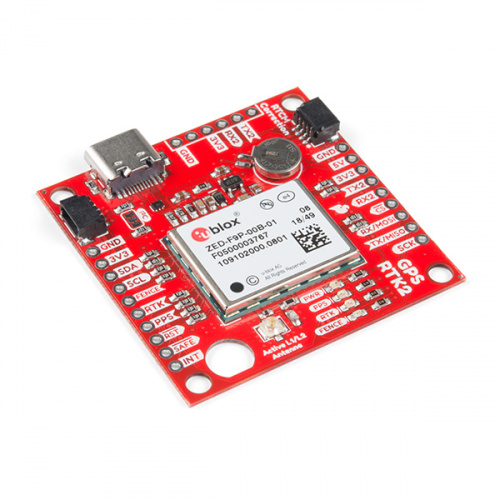
LuMini Ring Hookup Guide

$
0
0

LuMini Ring Hookup Guide a learn.sparkfun.com tutorial

Available online at: http://sfe.io/t841

Introduction

The LuMini rings (3 inch, 2 inch, 1 inch) are a great way to add a ring of light to just about anything.

SparkFun LuMini LED Ring - 3 Inch (60 x APA102-2020)

SparkFun LuMini LED Ring - 3 Inch (60 x APA102-2020)

COM-14965
$25.95
SparkFun LuMini LED Ring - 2 Inch (40 x APA102-2020)

SparkFun LuMini LED Ring - 2 Inch (40 x APA102-2020)

COM-14966
$15.95
SparkFun LuMini LED Ring - 1 Inch (20 x APA102-2020)

SparkFun LuMini LED Ring - 1 Inch (20 x APA102-2020)

COM-14967
$9.95

The LuMini line uses the same LED used on our Lumenati boards, the APA102, just in a smaller, 2.0x2.0 mm package. This allows for incredibly tight pixel densities, and thus, a more continuous ring of color. While the LuMini Rings come in different sizes, they all operate in a similar fashion.

Size of a APA102-2020 PackageAPA102, 5050 Package
Size of a APA102, 2020 PackageSize of a APA102, 5050 Package

In this tutorial, we’ll go over how to connect the LuMini rings up to more LuMini rings as well as other APA102 based products. We’ll check out how to map out a ring of lights in software so we can get a little more creative with circular animations. We’ll go over some things to consider as you string more and more lights together, and we’ll also go over some neat lighting patterns to get you away from that standard rainbow pattern (if you have 16 million colors why would you use 255).

Required Materials

To follow along with this tutorial, you will need the following materials. You may not need everything though depending on what you have. Add it to your cart, read through the guide, and adjust the cart as necessary.

Choosing a Microcontroller

You’ll need a microcontroller to control everything, however, there’s a few things to consider when picking one out for the purpose of controlling a whole ton of LED’s. The first thing is that, although they don’t have to operate at a specific timing, APA102 LED’s can transmit data really, really fast for LED’s, like 20 MHz fast. So you should use a microcontroller fast enough to take advantage of this fact. Another thing to consider when you start getting into higher LED counts is the amount of RAM taken up by the LED frame. Each LED takes up 3 bytes of space in RAM, which doesn’t sound like a lot, but if you’re controlling 5000 LED’s, well, you might need something with a bit more RAM than your traditional RedBoard. The below chart outlines the amount of LED’s where you may start running into memory issues. Keep in mind that these are very generous estimates and will decrease depending on what other global variables are declared.

MicrocontrollerMax LED'sClock Speed
SparkFun RedBoard60016 MHz
Arduino Mega 2560260016 MHz
Pro Micro70016 MHz
SparkFun ESP8266 Thing27,000160 MHz
SparkFun ESP32 Thing97,000160 MHz or 240 MHz
Teensy 3.687,000180 MHz (240 MHz Overclock)

It’s pretty easy to choose the ESP or Teensy when it comes to stuff like this, as you’ve got a ton of overhead in clock cycles to run wacky calculations for animations. However, if your project isn’t all about lights, and you’re just tossing a LuMini Ring on a project as an indicator, less powerful microcontrollers will suffice. Here are a few microcontrollers listed from the catalog. Depending on the development board, you may need to solder headers based on your personal preference.

SparkFun RedBoard - Programmed with Arduino

SparkFun RedBoard - Programmed with Arduino

DEV-13975
$19.95
39
SparkFun ESP32 Thing

SparkFun ESP32 Thing

DEV-13907
$21.95
60
Pro Micro - 5V/16MHz

Pro Micro - 5V/16MHz

DEV-12640
$19.95
70
Arduino Mega 2560 R3

Arduino Mega 2560 R3

DEV-11061
$38.95
53
Teensy 3.6 (Headers)

Teensy 3.6 (Headers)

DEV-14058
$33.25
5
SparkFun ESP8266 Thing - Dev Board (with Headers)

SparkFun ESP8266 Thing - Dev Board (with Headers)

WRL-13804
$17.95
6

Selecting a Power Supply

In most cases, your LED installation is gonna pull more than your board can handle (Depending on brightness and animation, anywhere from 100-250 LED’s can be too much for your board’s voltage regulator to handle) so you should snag a sweet 5V power supply that’s got enough wattage in the cottage for all of your LED’s. Here are a few 5V power supplies listed in our catalog. Just make sure to get the appropriate cable and adapter when connecting to your power hungry LEDs.

Wall Adapter Power Supply - 5V DC 2A (Barrel Jack)

Wall Adapter Power Supply - 5V DC 2A (Barrel Jack)

TOL-12889
$5.95
15
Mean Well Switching Power Supply - 5VDC, 20A

Mean Well Switching Power Supply - 5VDC, 20A

TOL-14098
$25.95
Mean Well LED Switching Power Supply - 5VDC, 5A

Mean Well LED Switching Power Supply - 5VDC, 5A

TOL-14601
$14.95

You can either estimate the necessary size of your power supply by taking the amount of LED’s and multiplying by 60 mA (0.06 A) which is the amount of current it takes to run an LED at full white. This calculation will give you the maximum amount of power your LED’s could draw, but most of the time, this is a gross overestimate of the amount of power you’ll actually end up consuming. Instead of calculating, I usually like to test my completed installation on a benchtop power supply using the brightest animation it’ll be running, and then add 20 or 30 percent to give myself a little wiggle room if I want to turn the brightness up in the future.

Power Supply - 80W DC Switching Mode

Power Supply - 80W DC Switching Mode

TOL-09291
$259.95
1

Tools

You will need a wire stripper, wire, soldering iron, solder, general soldering accessories. Tweezers are optional if you are soldering the surface mount decoupling capacitor to the back of the board.

Hook-Up Wire - Assortment (Solid Core, 22 AWG)

Hook-Up Wire - Assortment (Solid Core, 22 AWG)

PRT-11367
$16.95
29
Tweezers - Curved (ESD Safe)

Tweezers - Curved (ESD Safe)

TOL-10602
$3.95
5
Weller WLC100 Soldering Station

Weller WLC100 Soldering Station

TOL-14228
$44.95
Solder Lead Free - 15-gram Tube

Solder Lead Free - 15-gram Tube

TOL-09163
$3.50
2
Wire Strippers - 20-30AWG

Wire Strippers - 20-30AWG

TOL-14763
$14.95
1

Suggested Reading

If you aren’t familiar with the following concepts, we recommend checking out these tutorials before continuing.

Light

Light is a useful tool for the electrical engineer. Understanding how light relates to electronics is a fundamental skill for many projects.

How to Power a Project

A tutorial to help figure out the power requirements of your project.

Light-Emitting Diodes (LEDs)

Learn the basics about LEDs as well as some more advanced topics to help you calculate requirements for projects containing many LEDs.

Electric Power

An overview of electric power, the rate of energy transfer. We'll talk definition of power, watts, equations, and power ratings. 1.21 gigawatts of tutorial fun!

How to Work with Jumper Pads and PCB Traces

Handling PCB jumper pads and traces is an essential skill. Learn how to cut a PCB trace, add a solder jumper between pads to reroute connections, and repair a trace with the green wire method if a trace is damaged.

Hardware Overview

I/O Pins

The LuMini rings are powered and controlled using a few pads on the back of each board. Each board has a set of pads for 5V and ground, a set of pads for data and clock input, and a set of pads for data and clock output. These pads are outlined in the below image.

I/O Pads

I/O Pads

Decoupling Capacitor Pads

In larger installations you may need to add a decoupling capacitor between power and ground to prevent voltage dips when turning on a whole bunch of LED’s simultaneously. The spot to add this optional capacitor is outlined below.

Capacitor Pads

Capacitor Pads

We’d recommend the surface mount 4.7 µF capacitor that is shown below. If you’ve never done surface mount soldering before, this part might be a little tricky, but check out our SMD tips and tricks on doing just that.

Capacitor 4.7uF - SMD (Strip of 10)

Capacitor 4.7uF - SMD (Strip of 10)

COM-15169
$1.95

LED Numbers

Looking at the back of each ring, you’ll also see some numbers. Since the ring acts like a string of LEDs, these numbers correspond to the LED number in the string. Note that, like the led array, we index at LED 0, so calling leds[5] will correspond to the LED on the opposite side of the 5 labeling.

LED Numbers

LED Numbers

Hardware Assembly

Soldering to the LuMini Rings

Soldering wires to the pads on the LuMini rings is pretty simple. The trick is simply to pre-solder both the pad and stripped wire before attempting to solder the two together. Then, press the wire onto the pad and solder away! Check out the below GIF if you’re a little confused.

Soldering

Soldering to the LuMini Ring

Choosing Pins

The APA102 LED is controlled on an SPI-like protocol, so it’s generally good practice to connect CI to SCLK on your microcontroller, and connect DI to MOSI. However, This setup isn’t required, and you can connect data and clock up to most pins on your microcontroller. Go ahead and determine which pins you will use, and solder your Data (DI) and Clock (CI) lines into your microcontroller.

Now that we know how to solder to these pads, we can start making a chain of LuMini rings, or even chain them to other APA102 based products. To do this, all we’ll need to do is solder CO and DO of one ring to the CI and DI of the next ring. The below image has the output of a 1 inch ring connected to the input of a 3 inch ring.

Chained Rings

Chained Rings

Software Installation

Note: This example assumes you are using the latest version of the Arduino IDE on your desktop. If this is your first time using Arduino, please review our tutorial on installing the Arduino IDE. If you have not previously installed an Arduino library, please check out our installation guide.

We’ll be leveraging the ever popular FastLED library to control our LuMini rings. You can obtain these libraries through the Arduino Library Manager. Search for FastLED to install the latest version. If you prefer downloading the libraries manually, you can also grap them from the GitHub Repository:

DOWNLOAD THE FASTLED LIBRARY (ZIP)

Light It Up

SparkFun has also written some example code specific to the rings to get you started. These example sketches can be found in the LuMini 3-Inch GitHub Repo under Firmware. To download, click on the button below.

DOWNLOAD THE EXAMPLE SKETCHES (ZIP)

Make sure to adjust the pin definition depending on how you connected the LEDs to your microcontroller.

Example 1 — Ring Test

Glen Larson invented the Larson Scanner as an LED effect for the TV series Knight Rider. In this example, we’ll reproduce it, only we’ll add in some color for good measure. The Larson Scanner is a great and colorful way to test all of your LEDs on your ring. We’ll first begin by creating an object for our ring. Simply uncomment the proper number of LED’s for your ring of choice. For these examples, we’ll be using the 3 inch ring.

language:c
#include <FastLED.h>

// How many leds in your strip? Uncomment the corresponding line
#define NUM_LEDS 60 //3 Inch
//#define NUM_LEDS 40 //2 Inch
//#define NUM_LEDS 20 //1 Inch

// The LuMini rings need two data pins connected
#define DATA_PIN 16
#define CLOCK_PIN 17

// Define the array of leds
CRGB ring[NUM_LEDS];

We’ll then initialize a ring using the .addLeds function below. Notice the BGR in this statement, this is the color order, sometimes, the manufacturer will change the order in which the received data is put into the PWM registers, so you’ll have to change your color order to match. The particular chipset we’re using is BGR, but this could change in the future. We’ll also set the global brightness to 32.

language:c
void setup() {
  LEDS.addLeds<APA102, DATA_PIN, CLOCK_PIN, BGR>(ring, NUM_LEDS);
  LEDS.setBrightness(32);
}

Our animation is then contained in the fadeAll() function, which loops through every LED and fades it to a percentage of it’s previous brightness. Our loop() then set’s an LED to a hue, increments the hue, and then shows our LEDs. After this, we use the fadeAll() function to fade our LED’s down so they don’t all end up being on.

langauge:c
void fadeAll() {
  for (int i = 0; i < NUM_LEDS; i++)
  {
    ring[i].nscale8(250);
  }
}

void loop() {
  static uint8_t hue = 0;
  //Rotate around the circle
  for (int i = 0; i < NUM_LEDS; i++) {
    // Set the i'th led to the current hue
    ring[i] = CHSV(hue++, 150, 255); //display the current hue, then increment it.
    // Show the leds
    FastLED.show();
    fadeAll();//Reduce the brightness of all LEDs so our LED's fade off with every frame.
    // Wait a little bit before we loop around and do it again
    delay(5);
  }
}

Your code should look like the GIF below if you’ve hooked everything up right. If thing’s aren’t quite what you’d expect, double check your wiring.

Example 1 Output

Example 1 Output

Example 2 — RGB Color Picker

In this second example, we’ll use the serial terminal to control the color displayed by the ring. We initialize everything in the same way. We then listen for data on the serial port, parsing integers that are sent from the serial terminal on your desktop and putting them in the corresponding color (red, green or blue). The code to accomplish this is shown below.

language:c
#include <FastLED.h>

// How many leds in your strip?
#define NUM_LEDS 60 //3 Inch
//#define NUM_LEDS 40 //2 Inch
//#define NUM_LEDS 20 //1 Inch

//Data and Clock Pins
#define DATA_PIN 16
#define CLOCK_PIN 17

CRGB color;
char colorToEdit;

// Define the array of leds
CRGB ring[NUM_LEDS];

void setup() {
  Serial.begin(115200);
  Serial.println("resetting");
  LEDS.addLeds<APA102, DATA_PIN, CLOCK_PIN, BGR>(ring, NUM_LEDS);
  LEDS.setBrightness(32);

  //Display our current color data
  Serial.print("Red Value: ");
  Serial.println(color[0]);
  Serial.print("Green Value: ");
  Serial.println(color[1]);
  Serial.print("Blue Value: ");
  Serial.println(color[2]);
  Serial.println();      
}

void loop()
{
  if (Serial.available()) //Check to see if we have new Serial data.
  {
    colorToEdit = Serial.read();
    switch (colorToEdit)
    {
      case 'R':
      case 'r':
        color[0] = Serial.parseInt();
        break;
      case 'G':
      case 'g':
        color[1] = Serial.parseInt();
        break;
      case 'B':
      case 'b':
        color[2] = Serial.parseInt();
        break;
    }
    //Display our current color data
    Serial.print("Red Value: ");
    Serial.println(color[0]);
    Serial.print("Green Value: ");
    Serial.println(color[1]);
    Serial.print("Blue Value: ");
    Serial.println(color[2]);
    Serial.println();
    for (int i = 0; i < NUM_LEDS; i++)
    {
      ring[i] = color;
      FastLED.show();
      delay(10);
    }
  }
}

Go ahead and upload this code, then open your serial monitor to 115200. It should be displaying the current color value (R:0, G:0, B:0), if not.

RGB Color Picker

Changing the value of a color is done be sending the letter of the color (R, G, or B) followed by a value between 0 and 255. For instance, turning red to half brightness would be achieved by sending R127. Play around and look for your favorite color.

Example 3 — HSV Color Picker

The third example is very similar to the first in that we are picking colors using the serial terminal. However, in this example, we are working with an HSV color space. This sketch works mostly the same as the previous one, only we send h, s or v instead of r, g or b. Upload the below code and play around in search of your favorite color.

language:c
#include <FastLED.h>

// How many leds in your strip?
#define NUM_LEDS 60 //3 Inch
//#define NUM_LEDS 40 //2 Inch
//#define NUM_LEDS 20 //1 Inch

//Data and Clock Pins
#define DATA_PIN 16
#define CLOCK_PIN 17

CHSV color = CHSV(0, 255, 255);
char colorToEdit;

// Define the array of leds
CRGB ring[NUM_LEDS];

void setup() {
  Serial.begin(115200);
  Serial.println("resetting");
  LEDS.addLeds<APA102, DATA_PIN, CLOCK_PIN, BGR>(ring, NUM_LEDS);
  LEDS.setBrightness(32);

  //Display our current color data
  Serial.print("Hue: ");
  Serial.println(color.hue);
  Serial.print("Saturation: ");
  Serial.println(color.sat);
  Serial.print("Value: ");
  Serial.println(color.val);
  Serial.println();
}

void loop()
{
  if (Serial.available()) //Check to see if we have new Serial data.
  {
    colorToEdit = Serial.read();
    switch (colorToEdit)
    {
      case 'H':
      case 'h':
        color.hue = Serial.parseInt();
        break;
      case 'S':
      case 's':
        color.sat = Serial.parseInt();
        break;
      case 'V':
      case 'v':
        color.val = Serial.parseInt();
        break;
    }
    //Display our current color data
    Serial.print("Hue: ");
    Serial.println(color.hue);
    Serial.print("Saturation: ");
    Serial.println(color.sat);
    Serial.print("Value: ");
    Serial.println(color.val);
    Serial.println();

    for (int i = 0; i < NUM_LEDS; i++)
    {
      ring[i] = color;
      FastLED.show();
      delay(10);
    }
  }
}

Once again, play around to try and find your favorite color. I find that HSV is a much more intuitive space to work in than RGB space.

Example 4 — Angle Assignment

In this example, we’ll assign the LED’s in our circle to the angles of the unit circle so we won’t have to think about which LED corresponds to which angle. We’re also going to use 0-255 instead of 0-360, as this makes more sense from a computer standpoint. For example, the LED’s at 90° would be accessed by calling ringMap[64]. This is accomplished using the populateMap() function, which populates the uint8_t ringMap[255] object. The populateMap() function is shown below and gets called in our setup() loop.

language:c
#include <FastLED.h>

// How many leds in your strip?
#define NUM_LEDS 60 //3 Inch
//#define NUM_LEDS 40 //2 Inch
//#define NUM_LEDS 20 //1 Inch

//Data and Clock Pins
#define DATA_PIN 16
#define CLOCK_PIN 17

// Define the array of leds
CRGB ring[NUM_LEDS];
uint8_t ringMap[255];
uint8_t rotation = 0;

float angleRangePerLED = 256.0 / NUM_LEDS; //A single LED will take up a space this many degrees wide.

void populateMap () //we map LED's to a 360 degree circle where 360 == 255
{
  for (int ledNum = 0; ledNum < NUM_LEDS; ledNum++) //Loops through each LED and assigns it to it's range of angles
  {
    for (int j = round(ledNum * angleRangePerLED); j < round((ledNum + 1) * angleRangePerLED); j++)
    {
      ringMap[j] = ledNum;
    }
  }
}

void fadeAll(uint8_t scale = 250)
{
  for (int i = 0; i < NUM_LEDS; i++)
  {
    ring[i].nscale8(scale);
  }
}

void setup()
{
  Serial.begin(115200);
  FastLED.addLeds<APA102, DATA_PIN, CLOCK_PIN, BGR>(ring, NUM_LEDS);
  FastLED.setBrightness(32);
  populateMap();
}

In our loop, we’ll map each angle of the circle to a hue, then we’ll light up 3 pixels, each separated by 120° We do this by lighting an LED at a starting angle 0, then add 120° which corresponds to 85.333 ((120/360)*255 = 85.333) and light the LED at this angle. We repeat the same process to light the final LED. Each angle is matched to a hue, so we should see the same colors in each position.

language:c
void loop()
{
  for (int i = 0; i < 3; i++)
  {
    uint8_t angle = round(i * 85.3333) + rotation;
    ring[ringMap[angle]] = CHSV(angle, 127, 255);
  }
  FastLED.show();
  rotation++;
  fadeAll(248);
  delay(5);
}

Notice how ringMap[angle] is called within ring, as it will return the LED number at that angle. Uploading this code should look similar to the below GIF

Example 4 Output

Example 4 Output

Example 5 — Using Gradients

In this final example, we’ll leverage FastLED’s palette object (CRGBPalette16) to create and visualize a color palette on our ring. We have much the same initialization as our previous examples, only this time we also initialize a CRGBPalette16 object which will be full of colors along with a TBlendType which will tell us whether or not to blend the colors together or not. This can be either LINEARBLEND or NOBLEND. To populate this gradient, we use examples 2 and 3 to find the colors we want to put into our gradient. The gradient included is a bunch of colors created in HSV space, but you can easily change to RGB space if you prefer. You can also use any of the preset palettes by uncommenting the line that sets it equal to currentPalette.

language:c
TBlendType    currentBlending = LINEARBLEND;
CRGBPalette16 currentPalette = {
  CHSV(5, 190, 255),
  CHSV(0, 190, 255),
  CHSV(245, 255, 255),
  CHSV(235, 235, 255),
  CHSV(225, 235, 255),
  CHSV(225, 150, 255),
  CHSV(16, 150, 255),
  CHSV(16, 200, 255),
  CHSV(16, 225, 255),
  CHSV(0, 255, 255),
  CHSV(72, 200, 255),
  CHSV(115, 225, 255),
  CHSV(40, 255, 255),
  CHSV(35, 255, 255),
  CHSV(10, 235, 255),
  CHSV(5, 235, 255)
};

//currentPalette = RainbowColors_p;
//currentPalette = RainbowStripeColors_p;
//currentPalette = OceanColors_p;
//currentPalette = CloudColors_p;
//currentPalette = LavaColors_p;
//currentPalette = ForestColors_;
//currentPalette = PartyColors_p;

We then use the ColorFromPalette function to put the colors from our gradient onto our LED ring. Notice how we use the angle functions once again to map each part of the gradient to an angle.

language:c
void loop() {
  for (uint8_t i = 0; i < 255; i++)
  {
    uint8_t gradientIndex = i + rotation;
    ring[ringMap[i]] = ColorFromPalette(currentPalette, gradientIndex, brightness, currentBlending);
  }
  FastLED.show();
  rotation++;
  delay(20);
}

Play around with the colors in your palette until you’re satisfied. If all is hooked up correctly your ring should look something like the below GIF.

Example 5 Output

Example 5 Output

Additional Examples

There are quite a few additional examples contained in the FastLED library. While they aren’t made specifically for the rings, they can still show you some useful features in the FastLED library, and may give you some ideas for some animations of your own.

GitHub: FastLED > Examples

If the FastLED library is installed, they can be found from the Arduino IDE menu by opening up File ->Examples ->Examples From Custom Libraries ->FastLED .

Resources & Going Further

Now that you’ve successfully got your LuMini Ring up and running, it’s time to incorporate it into your own project! For more information about the LuMini Ring, check out the links below.

Lumini Ring 3 Inch

Lumini Ring 2 Inch

Lumini Ring 1 Inch


Looking for a different way of controlling the LuMini Rings? Check out the LuMini Drive to program the APA102's in Circuit Python.

New!

LumiDrive Hookup Guide

January 17, 2019

The LumiDrive LED Driver is SparkFun’s foray into all things Python on micro-controllers. With the SparkFun LumiDrive you will be able to control and personalize a whole strand of APA102s directly from the board itself.

Need some inspiration for your next project? Check out some of these related tutorials:

Using OpenSegment

How to hook up and use the OpenSegment display shield. The OpenSegment is the big brother to the Serial 7-Segment Display. They run on the same firmware, however the OpenSegment is about twice as big.

IR Control Kit Hookup Guide

How to get the most out of the infrared receivers and transmitters included in the IR Control Kit.

LED PomPom Headbands

Follow this tutorial to make your own light up PomPom headband! Try the beginner version if you are new to electronics or the advanced version if you have some more experience!

Addressable LED Neon Flex Rope Hookup Guide

The addressable (UCS1903) LED neon flex rope adds cool lighting effects for outdoor and indoor uses including in hallways and stairs, holiday lighting, and more! In this hookup guide, you will learn how to connect, power, and control the LED segments with an Arduino and the FastLED library.

Or check out these blog post:


learn.sparkfun.com | CC BY-SA 3.0 | SparkFun Electronics | Niwot, Colorado
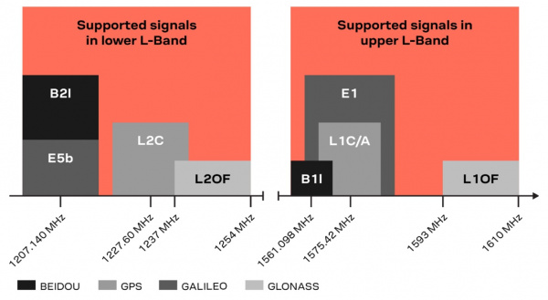

Qwiic OpenLog Hookup Guide

$
0
0

Qwiic OpenLog Hookup Guide a learn.sparkfun.com tutorial

Available online at: http://sfe.io/t865

Introduction

The SparkFun Qwiic OpenLog is the smarter and better looking cousin to the extremely popular OpenLog. We’ve ported the original serial based interface to I2C. Now you can daisy chain multiple I2C devices and log them all without taking up your serial port. Pop in a microSD card, write some simple code, and your data will be recorded to a text file on the microSD card.

SparkFun Qwiic OpenLog

SparkFun Qwiic OpenLog

DEV-15164
$16.95

Materials Required

In order to fully work through this tutorial, you will need the following parts. You may not need everything though, depending on what you have. Add it to your cart, read through the guide, and adjust the cart as necessary.

Recommended Reading

If you are not familiar or comfortable with the following concepts, we recommend reading through these before continuing on with the Qwiic OpenLog Hookup Guide.

Serial Communication

Asynchronous serial communication concepts: packets, signal levels, baud rates, UARTs and more!

I2C

An introduction to I2C, one of the main embedded communications protocols in use today.

Serial Terminal Basics

This tutorial will show you how to communicate with your serial devices using a variety of terminal emulator applications.

OpenLog Hookup Guide

An introduction to working with the OpenLog data logger.

Hardware Overview

Power

The Qwiic OpenLog runs at the following settings:

OpenLog Power Ratings
VCC Input3.3V-12V (Recommended 3.3V-5V)
RXI Input2.0V-3.8V
TXO Output3.3V
Idle Current Draw~2mA-5mA (w/out microSD card), ~5mA-6mA (w/ microSD card)
Active Writing Current Draw~20-23mA (w/ microSD card)

The Qwiic OpenLog’s current draw is about 20mA to 23mA when writing to a microSD. Depending on the size of the microSD card and its manufacturer, the active current draw can vary when the OpenLog is writing to the memory card. Increasing the baud rate will also pull more current.

Register Map

The Qwiic Open Log implements a register map type set up if you’d like to create your own library.

OpenLog Register Map

Having a hard time seeing? Click the image for a closer look.

Microcontroller

Like its predecessor, the Qwiic OpenLog runs off of an onboard ATmega328, running at 16MHz thanks to the onboard crystal. The ATmega328 has the Optiboot bootloader loaded on it, which allows the OpenLog to be compatible with the “SparkFun Redboard” board setting in the Arduino IDE.

ATMego328

The brain of the Qwiic OpenLog.

Interface

Qwiic Connectors

The primary interface with the Qwiic OpenLog are the Qwiic connectors on either side of the board. If you aren’t familiar with the Qwiic system, you are in for a treat! The Qwiic system utilizes I2C protocol to allow multiple “slave” digital integrated circuits (“chips”) to communicate with one or more “master” chips with a mere two wires. Check out all the benefits of the Qwiic System here.

Qwiic connectors

Qwiic Connectors

FTDI Header Pins

While the Qwiic OpenLog retains the broken out FTDI header pins, they pins are used specifically for reprogramming the firmware. All logging communication happens through the Qwiic lines and associated broken out pins.

Serial UART Pins

FTDI Header Pins

SPI

There are also six SPI test points broken out on the opposite side of the board. You can also use these to reprogram the bootloader on the ATmega328.

SPI Pins

SPI Test Points

microSD Card

The final interface for communicating with the Qwiic OpenLog is the microSD card itself. To communicate, the microSD card requires SPI pins. Not only is this where the data is stored by the OpenLog, but you can also update the OpenLog’s configuration via the config.txt file on the microSD card.

All data logged by the OpenLog is stored on the microSD card. The OpenLog works with microSD cards that involve the following features:

  • 64MB to 32GB
  • FAT16 or FAT32

microSD Slot

microSD Slot on the bottom of the Qwiic OpenLog

Status LED

There are two LEDs on the OpenLog to help you with troubleshooting.

  • STAT - This green LED is connected to Arduino D13 (Serial Clock Line/ ATmega328 PB5). This LED only blinks when the SPI interface is active. You will see it flash when the OpenLog records data to the microSD card.
  • PWR - This red indicator LED is attached to Arduino D5 (ATmega328 PD5) and lights when the board is active and functioning.

Power and Status LEDs

Status and Power LEDs on the Qwiic OpenLog

Hardware Hookup

If you’ve purchased the SparkFun RedBoard Qwiic, hardware hookup is as simple as plugging in your Qwiic cable!

Connected Qwiic OpenLog to SparkFun's Qwiic RedBoard

If, however, you are using an older SparkFun RedBoard, you’ll need an assembled Qwiic Shield, so if you haven’t done that yet, now would be the time to head on over to that tutorial.

Qwiic Shield for Arduino & Photon Hookup Guide

October 19, 2017

Get started with our Qwiic ecosystem with the Qwiic shield for Arduino or Photon.

Arduino Sketches

Note: This example assumes you are using the latest version of the Arduino IDE on your desktop. If this is your first time using Arduino, please review our tutorial on installing the Arduino IDE. If you have not previously installed an Arduino library, please check out our installation guide.

There are eleven examples in the Qwiic OpenLog Arduino Library that can be used when connected to a Qwiic OpenLog. These Arduino functions replace the serial command communication that occurred on the previous version of the OpenLog. These example files are named such that their functions should be self-explanatory, but in case you want more information, see the descriptions below. Head on over to the GitHub Page or feel free to download the library here!

SparkFun Qwiic OpenLog Arduino Library

  • Example1_WritingLog– This example shows how to record various text and variables to Qwiic OpenLog.

  • Example2_AppendFile– Arduino sketch showing how to append text to the end of File. If File does not exist when this function is called, the file will be created.

  • Example3_CreateFile– This example shows how to create a new file named File in the current directory. Standard 8.3 filenames are supported. For example, “87654321.123” is acceptable, while “987654321.123” is not.

  • Example4_ReadFileSize– This example shows how to record some strings to a default log, check the size of a given file name, and if the given file doesn’t exist, say so.

  • Example5_ReadFile– This example shows how to record some strings to a default log, check the size of a given file name, if that given file doesn’t exist, create it with random characters, and read back the contents of the given file (containing random characters)

  • Example6_MakeDirectory– This example shows how to create a directory, move into that directory called MONDAY, create a sub directory within MONDAY called LOGS, and create and write to a file inside MONDAY.

  • Example7_ReadDirectoryContents– This example shows how to read the files in a given directory. You can use wildcards if desired. This is handy for listing a certain type of file such as .LOG or LOG01.TXT.

  • Example8_RemoveDirectory– This example shows how to create a directory, create some files there, delete a specific file, delete *.TXT, and remove the directory we created.

  • Example9_ReadVersion– This example shows how to read the firmware version of Qwiic OpenLog.

  • Example10_CheckStatus– This example shows how to read the status byte of the OpenLog.

  • Example11_ChangeAddress– This example shows how to change the I2C address of the Qwiic OpenLog. It’s easy to change the I2C address. If you forget what the address is you can use the I2CScan Example to re-discover it. You can also close the ADR jumper on the board. This will force the I2C address to 0x29 regardless of any other setting or command.

    Valid I2C addresses are 0x08 to 0x77 (inclusive):

Firmware

The Qwiic OpenLog has two primary pieces of software on board: the bootloader and the firmware.

Arduino Bootloader

You can treat the Qwiic OpenLog just like a SparkFun Redboard when uploading example code or new firmware to the board.

If you end up bricking your Qwiic OpenLog and need to reinstall the bootloader, you will also want to upload Optiboot onto the board. Please check out our tutorial on installing an Arduino Bootloader for more information.

Compiling and Loading Firmware onto the Qwiic OpenLog

Note: If this is your first time using Arduino, please review our tutorial on installing the Arduino IDE. If you have not previously installed an Arduino library, please check out our installation guide to manually install the libraries.

If for any reason you need to update or reinstall the firmware on your OpenLog, the following process will get your board up and running.

First, download the Qwiic OpenLog firmware. You can go to the Qwiic OpenLog GitHub Page or download via the button here:

Download OpenLog Firmware (ZIP)

Once you have the firmware downloaded, install the libraries into Arduino. If you are unsure how to manually install the libraries in the IDE, please refer to the link above.

Download SerialPort (ZIP)Download SdFat)

If you haven’t yet, connect your OpenLog to the computer via an FTDI board. Please double check the example circuit if you are not sure how to do this properly. You will likely need to solder headers to the FTDI pins in order to access them. See our soldering tutorial if you need help here.

Open the OpenLog sketch you would like to upload under Tools>Board menu, select the “Arduino Redboard”, and select the proper COM port for your FTDI board under Tools>Port.

Upload the code.

That’s it! Your OpenLog is now programmed with new firmware. You can now open up a serial monitor and interact with the OpenLog. On power up, you will see either 12> or 12<. 1 indicates the serial connection is established, 2 indicates the SD card has successfully initialized and > indicates OpenLog is ready to receive commands.

Configuration File

The configuration file is not as relevant with the updated Qwiic OpenLog as it was with its predecessor. When you open the config file, you will see the I2C address, escape character, the number of escape characters, and the mode. You can edit the I2C address and the mode, but ignore the escape character and number of escape characters.

Troubleshooting

There are several different options to check if you are having issues connecting over the serial monitor, having issues with dropped characters in logs, or fighting a bricked OpenLog.

Check STAT1 LED Behavior

STAT1 LED shows different behavior for two different common errors.

  • 3 Blinks: The microSD card failed to initialize. You may need to format the card with FAT/FAT16 on a computer.
  • 5 Blinks: OpenLog has changed to a new baud rate and needs to be power cycled.

Double Check Subdirectory Structure

If you are using the default OpenLog.ino example, OpenLog will only support two subdirectories. You will need to change FOLDER_TRACK_DEPTH from 2 to the number of subdirectories you need to support. Once you’ve done this, recompile the code, and upload the modified firmware.

Verify the Number of Files in the Root Directory

OpenLog will only support up to 65,534 log files in the root directory. We recommend reformatting your microSD card to improve logging speed.

Verify the Size of your Modified Firmware

If you are writing a custom sketch for the OpenLog, verify that your sketch is not larger than 32,256. If so, it will cut into the upper 500 bytes of Flash memory, which is used by the Optiboot serial bootloader.

Double Check File Names

All file names should be alpha-numeric. MyLOG1.txt is ok, but Hi !e _.txt may not work.

Format your MicroSD Card

Remember to use a card with few or no files on it. A microSD card with 3.1GB worth of ZIP files or MP3s has a slower response time than an empty card.

If you did not format your microSD card on a Windows OS, reformat the microSD card and create a DOS filesystem on the SD card.

Swap MicroSD Cards

There are many different types of card manufacturers, relabeled cards, card sizes, and card classes, and they may not all work properly. We typically use a 16GB class 10 microSD card, which works well at 9600bps. If you are using an older card or anything less than class 6, you may want to try upgrading your SD card.

Add Delays Between Character Writes

By adding a small delay between Serial.print() statements, you can give OpenLog a chance to record its current buffer.

For example:

language:c
Serial.begin(115200);      
for(int i = 1 ; i < 10 ; i++) {
    Serial.print(i, DEC);     
    Serial.println(":abcdefghijklmnopqrstuvwxyz-!#");
}

may not log properly, as there are a lot of characters being sent right next to each other. Inserting a small delay of 15ms between large character writes will help OpenLog record without dropping characters.

language:c
Serial.begin(115200);      
for(int i = 1 ; i < 10 ; i++) {
    Serial.print(i, DEC);     
    Serial.println(":abcdefghijklmnopqrstuvwxyz-!#");
    delay(15);
}

Check with the Community

If you are still having issues with your Qwiic OpenLog, please check out the current and closed issues on our GitHub repository here. There is a large community working with the OpenLog, so chances are that someone has found a fix for the problem you are seeing.

Resources and Going Further

Now that you’ve successfully logged data with your Qwiic OpenLog, you can set up remote projects and monitor all the possible data coming in. Consider creating your own Citizen Science project, or even a pet tracker to see what Fluffy does when out and about!

For more information, check out the resources below:

Need some inspiration for your next project? Check out some of these related tutorials:

Photon Remote Water Level Sensor

Learn how to build a remote water level sensor for a water storage tank and how to automate a pump based off the readings!

mbed Starter Kit Experiment Guide

This Experiment Guide will get you started with the wonderful world of mbed microcontrollers. Need to find that next step after mastering the Arduino? This a great place to take those skills to the next level.

GPS Logger Shield Hookup Guide

How to assemble and hookup the SparkFun GPS Logger Shield. Never lose track of your Arduino again!

9DoF Razor IMU M0 Hookup Guide

How to use and re-program the 9DoF Razor IMU M0, a combination of ATSAMD21 ARM Cortex-M0 microprocessor and MPU-9250 9DoF-in-a-chip.

If you have any tutorial feedback, please visit the comments or contact our technical support team at TechSupport@sparkfun.com.


learn.sparkfun.com | CC BY-SA 3.0 | SparkFun Electronics | Niwot, Colorado
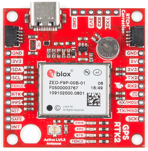
AST-CAN485 I/O Shield (24V) Hookup Guide

$
0
0

AST-CAN485 I/O Shield (24V) Hookup Guide a learn.sparkfun.com tutorial

Available online at: http://sfe.io/t867

Introduction

The AST-CAN485 I/O Shield (24) is an Arduino shield that will allow the user to interface the AST-CAN485 Dev Board with 24V inputs and outputs, which expands its usefulness into industrial systems.

SparkFun AST-CAN485 I/O Shield (24V)

SparkFun AST-CAN485 I/O Shield (24V)

DEV-14598
$19.95

Required Materials

To follow along with this tutorial, you will need the following materials. You may not need everything though depending on what you have. Add it to your cart, read through the guide, and adjust the cart as necessary.

Tools

Depending on your setup, you will need a soldering iron, solder, and general soldering accessories to solder pins to the AST-CAN485. You will also need a flat head and wire strippers to connect wires to the screw terminals.

Soldering Iron - 60W (Adjustable Temperature)

Soldering Iron - 60W (Adjustable Temperature)

TOL-14456
$12.95
7
Solder Lead Free - 15-gram Tube

Solder Lead Free - 15-gram Tube

TOL-09163
$3.50
2
Pocket Screwdriver Set

Pocket Screwdriver Set

TOL-12891
$3.95
3
Wire Strippers - 20-30AWG

Wire Strippers - 20-30AWG

TOL-14763
$14.95
1

Suggested Reading

We recommend checking out the AST-CAN485 Hookup Guide to get started with the board. Depending on your setup, you may need to install custom libraries and board add-ons.

AST-CAN485 Hookup Guide

March 1, 2018

The AST CAN485 is a miniature Arduino in the compact form factor of the ProMini. In addition to all the usual features it has on-board CAN and RS485 ports enabling quick and easy interfacing to a multitude of industrial devices.

Also, if you aren’t familiar with the following concepts, we recommend checking out these tutorials before continuing.

Working with Wire

How to strip, crimp, and work with wire.

Hardware Overview

Input Power

The AST-CAN485 I/O Shield provides a socket to break out all of the IO of the AST-CAN485 board. To make a secure connection to your industrial equipment, screw terminals come pre-soldered to the board to get you up and running in no time. The AST-CAN485 I/O Shield is designed to work in the industrial 24V environment, but has a wide supply input range of 7-24V. The board comes with input reverse voltage protection with a green and red status LEDs (green means power is connected properly, and red indicates reversed power, and blocks power to the rest of the board.

Power input highlight

24 I/O Pins

At your disposal are four 24V input channels with LEDs to indicate the input logic level, along with an additional four 24V output channels with matching indicator LEDs.

24V input and output highlights

RS-485 and CAN

Which do you prefer to use for your communication standard: RS-485 or CAN? Well it doesn’t matter because as the name indicates, the CAN485 board will handle them both, and they’re both broken out to the secure screw terminals as well!

RS-485 and CAN bus screw terminal highlight

SPI and I2C

If SPI and I2C are more in your wheelhouse, the CAN485 board breaks those out to screw terminals well, but you are limited to 5V logic.

SPI and I2C screw terminal highlight

AST-CAN485 Pins

All of the 5V logic level pins of the AST-CAN485 board are also broken out with an easy to read 2x13 pin header.

5V logic pin highlight

Pinouts

PinOuts

Image courtesy of AST

Having a hard time seeing? Click the image for a closer look.

Hardware Hookup

The AST-CAN485 I/O shield comes with female headers pre-soldered. Insert the CAN485 as shown with the FTDI header close to the input power pins:

Insert the Shield into the AST CAN485

Powering The Shield

The shield requires 24V power in order to function correctly. This can be supplied on any of the power terminals as shown below. Additional terminals are provided to allow powering of external devices.

There is reverse voltage protection on the 24V power terminals. The power status LED will show green for correctly wired power. If wired incorrectly, the LED will be red.

An integrated power supply regulates the 24V input power down to 5V which is used to provide power to the inserted CAN485 board. This 5V supply is also broken out to the terminals as shown.

Powering the Board

Software Setup and Programming

Note: This example assumes you are using the latest version of the Arduino IDE on your desktop. If this is your first time using Arduino, please review our tutorial on installing the Arduino IDE. If you have not previously installed an Arduino library or board add-on, please check out our library installation guide and instructions to install the AST-CAN485 board add-on files.

This board is a shield for the AST-CAN485 development board and is not programmed directly. There is a library for the CAN485 which enables some board features and contains some examples. It can be downloaded from the GitHub Repo or by clicking the button below to manually install.

AST V24IO Arduino Library (ZIP)

JTAG

One limitation of the shield is that JTAG debugging and Input 24V I1 cannot be used at the same time. Input V24 I1 is connected to pin A6 on the CAN485, this pin is also used for JTAG debugging. In order to use that input channel, JTAG debugging must be disabled. This is done automatically when calling the board initialization function provided by the library.

Examples

The library also includes several examples which demonstrate the use of the board. After installing the library, open up one the examples listed in the folder File > Examples > AST_V241O through the Arduino IDE. Select the CAN485 as the board, the COM port that it enumerated on, and hit upload to test.

  • BlinkOneOutput– Turn 24V O1 (D4) on and off.
  • CycleOutputs– Toggle all pins connected to the 24V output.
  • ReadInputs– Read all 24V input pins and print to serial monitor at a baud rate of 1000000.
  • ReadInputsToOutputs– Read the inputs and toggle outputs.

Resources and Going Further

For more information, refer to the links below:

AST-CAN485 I/O Shield (24V)

AST-CAN485 Development Board

Need some inspiration for your next project? Check out some of these related tutorials:

OBD II UART Hookup Guide

How to start working with the OBD-II Uart board.

CAN-BUS Shield Hookup Guide

A basic introduction to working with the CAN-Bus shield.

Getting Started with OBD-II

A general guide to the OBD-II protocols used for communication in automotive and industrial applications.

Or dig in further with According to Pete for more information about RS485.


learn.sparkfun.com | CC BY-SA 3.0 | SparkFun Electronics | Niwot, Colorado
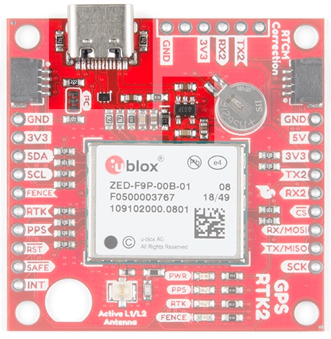
AST-CAN485 WiFi Shield Hookup Guide

$
0
0

AST-CAN485 WiFi Shield Hookup Guide a learn.sparkfun.com tutorial

Available online at: http://sfe.io/t828

Introduction

What would make the AST-CAN485 even better? WiFi! In order to further the communications capabilities of the CAN485, we present the AST-CAN485 Wifi Shield. The shield is based on the Sparkfun ESP8266 thing and allows for a CAN485 module to communicate over Wifi.

SparkFun AST-CAN485 WiFi Shield

SparkFun AST-CAN485 WiFi Shield

WRL-14597
$16.95

Required Materials

To follow along with this tutorial, you will need the following materials. You may not need everything though depending on what you have. Add it to your cart, read through the guide, and adjust the cart as necessary.

Suggested Reading

We recommend checking out the AST-CAN485 Hookup Guide to get started with the board. Depending on your setup, you may need to install custom libraries and board add-ons.

AST-CAN485 Hookup Guide

March 1, 2018

The AST CAN485 is a miniature Arduino in the compact form factor of the ProMini. In addition to all the usual features it has on-board CAN and RS485 ports enabling quick and easy interfacing to a multitude of industrial devices.

If you aren’t familiar with the following concepts, we also recommend checking out these tutorials before continuing.

Working with Wire

How to strip, crimp, and work with wire.

ESP8266 Thing Development Board Hookup Guide

An overview of SparkFun's ESP8266 Thing Development Board - a development board for the Internet of Things.

Three Quick Tips About Using U.FL

Quick tips regarding how to connect, protect, and disconnect U.FL connectors.

Hardware Overview

Input Power

The AST-CAN485 WiFi Shield provides screw terminals for your power, RS-485 signals, and CAN bus signals, presoldered to the board for fast and secure connections.

screw terminal highlight

The input voltage range is 7-24VDC. The input voltage is regulated down to 5V to supply power the CAN485 board, as well as 3.3V to power the ESP8266.

Integrated power highlight

SPI and UART

With the on-board ESP8266, you can communicate with your CAN485 board using either SPI or UART. Based on the SparkFun ESP8266 Thing, you can use either the PCB trace antenna, or the U.FL connector if housed in a metal enclosure.

ESP8266 highlight

Programming Switch

Because the UARTs are connected together for the CAN485 board and the ESP8266, a switch is used to separate the RX and TX signals. When programing either the ESP8266 or CAN485 board, move the switch over to the PROG position, and after the upload is complete, toggle the switch to the RUN position.

Switch highlight

Speaking of programming, the ESP8266 runs off of 3.3V logic, so to program the ESP8266, a 3.3V USB to UART bridge is used.

FTDI programming header hightlight

AST-CAN485 Serial Port

A header breaks out the Software Serial port used by the CAN485. This can be used as a debugging serial port or to connect other devices.

Software Serial Highlight

Pinouts

The pinout for the WiFi Shield is shown below:

Listed PinOuts

Image courtesy of AST

Schematic

The schematic below shows the layout of the interconnects between an inserted CAN485 module and the integrated ESP module.

Schematic of connection between inserted CAN485 module and the integrated ESP module

Image courtesy of AST

The primary interface between the CAN485 and the ESP8266 is a serial port. It operates on hardware serial port 0 on the CAN485 rather than the traditional Software Serial port. The reason for this is that it enables higher speed communications between the two devices. The trade-off of this feature is that it uses the main serial port, which is also used to program the CAN485 and is broken out on its FTDI header. This means that in order to program the CAN485 module, while it is inserted, the serial port must be disconnected. For this reason, the mode selection switch was added which allows for the rx and tx lines to be disconnected. In a similar way, the same serial port is used to both program the ESP8266 and communicate with the CAN485. The mode selection switch also enables the ESP to be programmed by disconnecting it from the CAN485.

Hardware Hookup

The AST-CAN485 WiFi Shield comes with headers pre-soldered to the board. Insert the CAN485 as shown with the CAN485's FTDI header close to the ESP8266.

WiFi Shield with CAN485 Inserted

Powering The Board

The Shield can be powered through the screw terminals. While the power input is intended to be supplied with 24V, an input voltage of 7-24V may be used.

An integrated power supply regulates the 24V input power down to 5V which is used to provide power to the inserted CAN485 board. This is further regulated down to 3.3V to power the ESP module.

It is also possible to power the board using the raw input pin of the CAN485 module. However, use of an external 24V supply is recommended and is the intended use case.

Providing power to the board

Image courtesy of AST

Software Setup and Programming

Note: This example assumes you are using the latest version of the Arduino IDE on your desktop. If this is your first time using Arduino, please review our tutorial on installing the Arduino IDE. If you have not previously installed an Arduino library or board add-on, please check out our library installation guide and instructions to install the AST-CAN485 board add-on files.

The Programming Mode Selection Switch

The ESP and CAN485 modules are connected using a hardware serial port. The same port is used to program either of the devices. It is therefore necessary to disconnect the serial port in order to program either of the devices. A selector switch is provided in order to make this possible.

If the selector switch is set to RUN, the ESP and CAN485 are connected via a serial port. If the switch is set to PROG, the serial port is disconnected and the devices may be programmed.

Programming Selector Port

Setup Arduino For ESP Programming

There are many options for programming ESP8266 based devices. The approach recommended by this guide is to make use of the ESP8266 Arduino Addon which has been developed by the ESP community. The Addon can be downloaded via the GitHub Repository or by clicking the button below.

ESP8266 Github Repository

This implementation is based on the ESP8266 Thing and the same setup instructions may be used. For more information, refer to the ESP8266 Thing Hookup Guide.

ESP8266 Thing Development Board Hookup Guide

November 5, 2015

An overview of SparkFun's ESP8266 Thing Development Board - a development board for the Internet of Things.

If you have not previously installed an Arduino library, please check out our installation guide.

Installing an Arduino Library

January 11, 2013

How do I install a custom Arduino library? It's easy! This tutorial will go over how to install an Arduino library using the Arduino Library Manager. For libraries not linked with the Arduino IDE, we will also go over manually installing an Arduino library.

Programming the ESP

The following process is followed in order to program the ESP module:

  • Switch the mode selection switch to PROG.
  • Insert a 3.3V FTDI into the FTDI header.
  • Hold down the ESP programming button and upload a sketch.
  • Return the mode selection switch to RUN to reconnect the devices.

Programming the ESP Module

Programming the ESP Module

Image courtesy of AST

Programming the CAN485

The following process is followed in order to program the CAN485 module:

  • Switch the mode selection switch to PROG.
  • Connect a 5V FTDI to the FTDI header on the CAN485 module.
  • Upload a sketch
  • Return the mode selection switch to RUN to reconnect the devices.

Programming the Inserted CAN485 Module

Programming Inserted CAN485 Module

Image courtesy of AST

Examples

The WiFi Shield GitHub Repository includes a few examples which demonstrate the use of the board. After downloading the repository, open up one the examples in the Arduino IDE. Select the CAN485 as the board, the COM port that it enumerated on, and hit upload to test.

Basic Serial Example

This example demonstrates serial communication between and inserted CAN485 and the on board ESP8266. Each device has a built in LED which is controlled by the other device over the serial port. Operation is as follows:

  • The CAN485 sends a command to the ESP every 100 ms.
  • The ESP sets its LED on or off depending on the command.
  • The ESP sends the same command back to the CAN485.
  • The CAN485 sets its LED depending on the command received by the ESP.

In addition to the examples in the WiFi Shield GitHub Repository, there are a number of examples using the ESP8266 in the ESP Arduino Library. These are accessible in the Arduino IDE under File>Examples. Examples may also be found in the ESP Github Community Forum.

Resources and Going Further

For more information, check out the resources below:

AST-CAN485 WiFi Shield

AST-CAN485 Dev Board

Need some inspiration for your next project? Check out some of these related tutorials:

OBD II UART Hookup Guide

How to start working with the OBD-II Uart board.

CAN-BUS Shield Hookup Guide

A basic introduction to working with the CAN-Bus shield.

Getting Started with OBD-II

A general guide to the OBD-II protocols used for communication in automotive and industrial applications.

Or dig in further with According to Pete for more information about RS485.


learn.sparkfun.com | CC BY-SA 3.0 | SparkFun Electronics | Niwot, Colorado
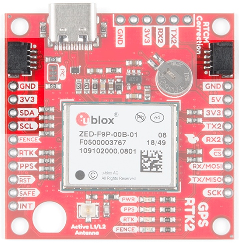
Everything You Should Know About HyperDisplay

$
0
0

Everything You Should Know About HyperDisplay a learn.sparkfun.com tutorial

Available online at: http://sfe.io/t863

Introduction

Nobody wants to reinvent the wheel, right? Well that's just what it felt like we were doing every time we wrote another (slightly different) graphics library for new products like the RGB OLED Breakout and ePaper displays. Not to mention that having to use specific code for each product makes it very hard to start using a new display in a project. Our HyperDisplay library is designed to put an end to all that - making it easy to add support for and use new displays!

The goal of this tutorial is to get you up-to-speed on how to use HyperDisplay, from the basics all the way to being able to extend the library. Stick around to learn all about how to use this easy, powerful, and flexible new tool!

The subjects that we cover in various sections will progress from fundamental all the way to the most advanced use of the library. Feel free to read the parts you need and skim the rest - you can always come back for more.

Tutorial Sections

Mandelbrot Set Fractal Shown with HyperDisplay

What is HyperDisplay?

HyperDisplay was created with the following goals in mind:

  • Standardize a graphics library so that the same code will work for any display
  • Reduce the duplicated work of adding support for new display technologies
  • Use a general interface that can be simplified when not needed
  • Make it easier to create graphical user interfaces

Those goals are met by modularity, default parameters in drawing functions, the windows feature, and buffered drawing mode.

Modularity

Standardization and easy extensibility is achieved by making HyperDisplay modular. There are up to three levels of code that all work together.

  • Top Level: HyperDisplay
    • HyperDisplay itself is the top level and it contains the standardized drawing interface. This includes all of the drawing, window, and buffering options.
    • A few functions, like that to draw a single pixel, are left as pure virtual to indicate that they must be implemented by a lower level
    • The remainder of functions are all defined in terms of these pure virtual functions so that as long as they are implemented the whole HyperDisplay suite will be available
    • There are some optional functions that can be re-written to provide extra speed or additional capabilities for a particular display
  • Mid Level: Drivers, ICs
    • It is possible to make a fully functional HyperDisplay driver at this level just by implementing the required functions
    • Often at this level we will represent the internal workings of the integrated circuit that is used to run a whole genre of display, such as the ILI9163C used to control TFT LCD screens
  • Bottom Level: Specific Products
    • Drivers based on mid-level layers
    • Represent a particular interface type (e.g. SPI vs I2C vs parallel)
    • Represent the physical dimensions of the display

That is as much as you need to know about the modularity for now. At the end of the tutorial we will cover how to create a driver of your own.

Default Parameters

A simple interface helps avoid confusion. It would be unfortunate to need a whole slew of possible functions like drawRectangle() and drawThickRectangle() and drawThickFilledInRectangle() -- how would you ever know where to start? In HyperDisplay we make use of the default parameters in C++ which allows you to use each drawing function with only the information that you need. As the core of a graphics library we will present the drawing functions in two parts:

  • Simply, with just enough information to use the color of your choice
    • E.g. line( x0, y0, x1, y1, width, color );
  • In full complexity, with the option to use repeating patterns of color and additional arguments
    • E.g. line( x0, y0, x1, y1, width, color, colorCycleLength, startColorOffset, reverseGradient);

Windows Feature and Buffered Drawing

With the creation of HyperDisplay was the opportunity to add something that was missing from other microcontroller graphics libraries; namely being able to draw in 'windows' like on a computer. Buffered drawing is available as an option when memory constraints are not a concern. Now it is easier to create GUIs, animations, and, with some creativity, even translucent layered images.

Now read on to learn how to install HyperDisplay and get started!

Installing HyperDisplay

Note: This example assumes you are using the latest version of the Arduino IDE on your desktop. If this is your first time using Arduino, please review our tutorial on installing the Arduino IDE. If you have not previously installed an Arduino library, please check out our installation guide.

Installing the HyperDisplay Library

Remember that HyperDisplay is a three-level layer cake, and you need all three layers to make it do anything useful. The top layer is always the main HyperDisplay library, which is available in the Arduino library manager. In the Arduino IDE, navigate to Sketch>Include Library>Manage Libraries. Then in the search box, begin searching for "SparkFun HyperDisplay" Once your search is narrowed down, select the SparkFun HyperDisplay library and click "Install."

Installing the SparkFun HyperDisplay Library via library manager

Otherwise, you can manually download the library. Navigate to GitHub repository and download the repository as a ZIP folder (or click the link below):

To manually install the library via a ZIP folder, open Arduino, navigate to Sketch>Include Library>Add .ZIP Library, and select the ZIP folder you just downloaded.

Installing the HyperDisplay Compatible Library

The middle layer will be a HyperDisplay compatible library that is designed to work on the actual chip that runs the display. This part will be specific to the display that you want to use so you should use the Library Manager link in the example sketches that you can get from the product page.

Installing the Driver Specific Library

The final layer is specific to the exact product that you are using because the particular interface (e.g. SPI vs I2C) and the particular resolution of the screen might vary even with the same driver IC. Again, get this library from the product page of the display that you are using.

Once you know where to find all of the required layers, check out our guide on Installing an Arduino Library to get set up.

Installing an Arduino Library

January 11, 2013

How do I install a custom Arduino library? It's easy! This tutorial will go over how to install an Arduino library using the Arduino Library Manager. For libraries not linked with the Arduino IDE, we will also go over manually installing an Arduino library.

With everything installed you can make sure all is well by choosing an example sketch from the bottom level library and trying to compile it. When everything is working move on to the next section to start learning about the basic use of the drawing functions.

Basic Drawing Functions

To avoid a severe case of infoxicity it is best to start out with HyperDisplay a little bit at a time. The first two things that you'll need to know about are how colors are handled and how to use the drawing functions in their minimal form.

Colors in HyperDisplay

Displays come in, well, all shapes and colors! From monochrome LCDs and OLEDs to full-color TFT and LED displays, not to mention the unique three-color ePaper displays, there is a lot to cover. Since HyperDisplay is designed to accommodate all of these displays and more, we had to consider how to represent all of the colors that a user might choose. How can we solve that problem? Using three bytes to represent Red, Green, and Blue channels for each pixel is certainly good enough to represent all the colors that current display technology can show, but it would be overkill for something like a dot matrix display that could actually store 24 pixels worth of information in that same space.

The solution was to leave the representation of colors up to the hardware-specific layers. Still, the top level HyperDisplay functions need to know at least where to find the information about the color. This naturally leads to the use of a pointer as the color argument in HD functions. What that looks like in code is this:

language:c
// Ways to make a hawrdware-specific color variable
hwColor myColor0 = RED; // Using a pre-defined constant or another color
hwColor myColor1 = 0x01; // Specifying the single-byte value (if applicable)
hwColor myColor2 = {0x00, 0x00, ... , 0x00 }; Specifying the value of each byte in a structure (if applicable)
hwColor myColor3 = converterFunctionRGB( redVal, greenVal, blueVal); // Using a function that returns the desired color based in inputs

// Making your color into a HyperDisplay color pointer
color_t myHDColor = (color_t)&myColorN; // The '&' takes the location of your color in memory, and (color_t) casts that location to a HD color type

Simple Drawing Usage

In the simplest case, to draw something you'll need to know where to draw it and what color to use. You can draw individual pixels, x or y lines, point-to-point lines, rectangles, circles, and even polygons! You can also fill the entire window with a certain color in one fell swoop.

The coordinates are zero-indexed so that the first pixel is number 0 (in x or y directions) and the last pixel on the screen in N-1 when you have N pixels in a given direction. The variable type for coordinates is 'hd_extent_t' which is specified to be a float so any number you pass in should work.

Here are the basic functions that you can use:

  • pixel( x0, y0, color )
    • Sets the pixel at ( x0, y0 ) to the color that exists at color
  • xline( x0, y0, length, color )
    • Draws a line from ( x0, y0 ) to ( x0 + (length - 1), y0 ) with color
  • yline( x0, y0, length, color )
    • Draws a line from ( x0, y0 ) to ( x0, y0 + (length - 1) ) with color
  • line( x0, y0, x1, y1, width, color )
    • Daws a line from ( x0, y0 ) to ( x1, y1 ) with color and width
  • rectangle( x0, y0, x1, y1, filled, color )
    • Draws a rectangle with corners at ( x0, y0 ), ( x0, y1 ), ( x1, y0 ), and ( x1, y1 ) that can be optionally filled in (when 'true') with color
  • circle( x0, y0, radius, filled, color )
    • Draws a circle centered at ( x0, y0 ) with radius that can be optionally filled with color
  • polygon( x[], y[], numSides, width, color )
    • Connects numSides points with numSideslines in a closed shape with width and color. x[] and y[] should be arrays of floats that represent your coordinates
  • fillWindow( color )
    • Fills the entire current window with color

Thanks to automatic casting in C++, you will be able to put any numerical variable in the x or y parameters, except for in the 'polygon' function, in which case they will need to be of the type hd_extent_t.

These functions also support default values - for example the color never has to be specified. If left out, HyperDisplay will use the 'current' color for the window which can be changed by using:

  • setCurrentWindowColorSequence( color )

Additionally, the filled parameter will default to 'false' and the width parameter will default to '1.'

Basic Drawing Output from TFT Examples

The function to set the current window color hints at a few of the more advanced features that will be discussed next, particularly why we say 'color sequence' instead of just 'color'. Check out the next section to find out!

Advanced Drawing Functions

The advanced HyperDisplay drawing functions are actually the same functions that you already know, but this time with less hand holding!

Color Cycles

In the previous section we only used a single color to draw our images. HD, however, supports repeating 'color cycles' in all drawing functions. This makes it easy to create repeating patterns without using a lot of memory. There are three things you need to specify when creating a color sequence.

  • A contiguous array - this is an array of your color type (as defined by the hardware being used) where the data parameter points to the first element
  • colorCycleLength - The length of your cycle in the number of color type objects
  • startColorOffset - The offset at which to start from the first object

After the color cycle specification, it is possible to adjust the direction (and, in the case of the rectangle, the axis alignment) by using boolean arguments in every function except the single pixel. Below are the full declarations with variable types shown for the curious.

  • voidpixel( hd_extent_tx0, hd_extent_ty0, color_tdata = NULL, hd_colors_tcolorCycleLength = 1, hd_colors_tstartColorOffset = 0);

  • voidxline( hd_extent_tx0, hd_extent_ty0, hd_extent_tlen, color_tdata = NULL, hd_colors_tcolorCycleLength = 1, hd_colors_tstartColorOffset = 0, boolgoLeft = false);

  • voidyline( hd_extent_tx0, hd_extent_ty0, hd_extent_tlen, color_tdata = NULL, hd_colors_tcolorCycleLength = 1, hd_colors_tstartColorOffset = 0, boolgoUp = false);

  • voidrectangle( hd_extent_tx0, hd_extent_ty0, hd_extent_tx1, hd_extent_ty1, boolfilled = false, color_tdata = NULL, hd_colors_tcolorCycleLength = 1, hd_colors_tstartColorOffset = 0, boolreverseGradient = false, boolgradientVertical = false);
  • voidfillFromArray( hd_extent_tx0, hd_extent_ty0, hd_extent_tx1, hd_extent_ty1, color_t data = NULL, hd_pixels_tnumPixels = 0, boolVh = false);
  • voidfillWindow( color_tcolor = NULL, hd_colors_tcolorCycleLength = 1, hd_colors_tstartColorOffset = 0);

  • uint16_tline( hd_extent_tx0, hd_extent_ty0, hd_extent_tx1, hd_extent_ty1, uint16_twidth = 1, color_tdata = NULL, hd_colors_tcolorCycleLength = 1, hd_colors_tstartColorOffset = 0, boolreverseGradient = false);

  • voidpolygon( hd_extent_tx[], hd_extent_ty[], uint8_tnumSides, uint16_twidth = 1, color_tdata = NULL, hd_colors_tcolorCycleLength = 1, hd_colors_tstartColorOffset = 0, boolreverseGradient = false);
  • voidcircle( hd_extent_tx0, hd_extent_ty0, hd_extent_tradius, boolfilled = false, color_tdata = NULL, hd_colors_tcolorCycleLength = 1, hd_colors_tstartColorOffset = 0, boolreverseGradient = false);

Have fun trying out these full functions and see what you can make with them!

Advanced Drawing Output from TFT Examples

Okay, so HyperDisplay seems pretty easy to use at first but is also very capable! Ready to call it quits? Not so fast -- we still can go over the use of windows and buffering, and also a guide on how to create a HyperDisplay driver for your own display. So grab a snack and then move onto the next section!

Using Windows

If you've only tried out the functions that have been presented so far (and haven't done any super-sleuthing in the source code) then you've just put pixels right where they ought to go in terms of the physical screen... Well I'm here to tell you that it doesn't have to be that way!

When we designed HyperDisplay, we wanted to make it better than the other options available for small-ish microcontrollers. One thing that always bugged me was having to write complicated expressions for my X and Y coordinates to account for other things on the screen, particularly when they might move. The solution is to allow things to be drawn in windows. So anything that needs to stay in one position with respect to another element can be grouped into a window, and then that window can be moved around easily.

When using a drawing function, you are drawing into the currently selected window for the display and if left untouched that window is equivalent to the physical hardware of the display so HD feels like any other graphics library.

Window Info Structure

The wind_info_t type contains information about location, text printing, color sequence, and memory.

language:c
  typedef struct window_info{
    hd_hw_extent_t  xMin;                      // FYI window min/max use the hardware frame of reference
    hd_hw_extent_t  xMax;         
    hd_hw_extent_t  yMin;         
    hd_hw_extent_t  yMax;       
    hd_extent_t     cursorX;                  // Where the cursor is currently in window-coordinates
    hd_extent_t     cursorY;                  
    hd_extent_t     xReset;                 
    hd_extent_t     yReset;                  
    char_info_t     lastCharacter;           
    color_t         currentSequenceData;      // The data that is used as the default color sequence
    hd_colors_t     currentColorCycleLength;  
    hd_colors_t     currentColorOffset;       
    bool            buffer;                   // Indicates either buffer or direct mode (direct is default)
    color_t         data;                     
    hd_pixels_t    numPixels;                
    bool            dynamic;                  
  }wind_info_t;                               // Window infomation structure for placing objects on the display 

Window Location Variables

The location variables are specified in terms of the physical hardware coordinates of the display - this is how you set the size and position of the window. When windows don't match the screen dimensions they will restrict drawing to within their bounds so it is OK to present negative or large values as arguments to drawing functions. Additionally, windows are allowed to run off of the screen, in which case pixels drawn off of the hardware will not be shown (so there is no need to worry about incorrect hardware access). The location of the window is specified by:

  • xMin
  • xMax
  • yMin
  • yMax

Text Tracking

Next in the list are five parameters that are used to track text. These values are in window coordinates so that (0, 0) is always in the upper-left corner of the window, no matter where on the screen the window is. Variables 'cursorX' and 'cursorY' keep track of where the next character will try to be printed. On the other hand 'xReset' and 'yReset' keep track of where the cursor will be after a reset. Finally 'lastCharacter' is used to keep track of what the previous character was - currently it is used to avoid performing two newlines when a newline needs to wrap around the window.

  • cursorX
  • cursorY
  • xReset
  • yReset
  • lastCharacter

  • You can use setTextCursor( int32_tx0, int32_ty0, wind_info_t * window = NULL); to modify the current cursor location of a given window (current window by default).

  • You can use resetTextCursor( wind_info_t * window = NULL); to put the cursor back to the reset location.

Default Color Cycle

Window information structures also keep track of the default color cycle to use if none is given for a drawing function. These three variables are just like those three that can be passed into the drawing functions:

  • currentSequenceData
  • currentColorCycleLength
  • currentColorOffset

  • setWindowColorSequence( wind_info_t * wind, color_tdata = NULL, hd_colors_tcolorCycleLength = 1, hd_colors_tstartColorOffset = 0); is used to set the current color cycle for a given window. and

  • setCurrentWindowColorSequence( color_tdata = NULL, hd_colors_tcolorCycleLength = 1, hd_colors_tstartColorOffset = 0); will set the current color cycle for the current window.

Buffering

The last job of the window information structure is to hold information about buffering, which we will discuss in the next section so sit tight.


The best way to learn about the windows feature of HyperDisplay is to try it out, but here's an incomplete list of things you can do:

  • Simplify drawing by using a default color
  • Create simple animations of complex arrangements
  • Overlay text onto images
  • Create easier GUIs

Characters

HyperDisplay comes with a default font but like everything else in HD it is totally customizable by YOU! When you call a 'print' function (they are just like the normal Arduino print functions) it in turn calls a 'write' function for each character that is handled by HyperDisplay. In 'write()' hyperdisplay uses a char_info_t object to figure out what to do next, such as show the character, skip it, or cause a newline. Additionally the object describes how to construct the character. To get the information for the character information structure HD uses a function called 'getCharInfo().'

  • virtual voidgetCharInfo( uint8_tcharacter, char_info_t * pchar);

By rewriting this function you can cause any symbol to be printed out for any character that might be requested, as long as the symbol can be drawn in a rectangular area. To implement the function you will need to fill out the char_info_t object that the 'pchar' pointer points to with the information that you want.

A full example of creating your own font doesn't exist yet but may be added in the future. If you're feeling brave we'd certainly appreciate a pull request on the HyperDisplay Repo!

language:c
typedef struct character_info{
    color_t             data;                       // The data that is used to fill the character frame
    hd_font_extent_t*   xLoc;                       // x location data relative to the upper left-corner of the character area
    hd_font_extent_t*   yLoc;                       // y location data relative to the upper left-corner of the character area
    hd_font_extent_t    xDim;                       // The maximum value of xLoc
    hd_font_extent_t    yDim;                       // The maximum value of yLoc - also the number of pixels to move down for characters that cause new lines
    hd_pixels_t         numPixels;                  // The number of color_t types that pdata points to
    bool                show;                       // Whether or not to actually show the character
    bool                causesNewline;              // This indicates if the given chracter is meant to cause a newline
}char_info_t;                               // Character information structure for placing pixels in a window

Windowed Drawing Output from TFT Examples

Okay, windows are neat and all but it's a bummer that they don't have any memory of what was drawn in them, right? Actually they can! Read on to figure that one out.

Buffering

Memory is a touchy subject on microcontrollers and embedded systems. Particularly on the ever-popular AtMega 328p you need to conserve every byte of memory that you can and for that reason HyperDisplay defaults to running in an unbuffered mode (except in some cases where the display hardware demands a buffer). However, operating this way means that you have to watch the drawing operations take place in real time. To avoid this, and also enable other cool features such as (possibly) layer transparency we need to keep record of what is on the screen. This is where the buffered drawing mode comes into play.

Fortunately, running in buffered mode is really easy! All you need to do is allocate memory for your buffer (big enough to hold all the pixels), tell your buffered window where to find that memory, and switch it into buffered mode. Once in buffered mode drawing functions won't appear on the screen until 'show()' is called. In the meantime the data will be rerouted to the buffer you provided. Here's how that process might look in code:

language:c
hwColor_t smallWindowMem[32*64];    // Reserve 32*64 pixels worth of memory

wind_info_t smallWindow;            // Create a window
smallWindow.xMin = 16;              // Set the paramters to match the buffer size
smallWindow.yMin = 72;      
smallWindow.xMax = 16 + 31;         // See, 16+0 would be one pixel, so 16+31 is actually 32 pixels wide
smallWindow.yMax = 72 + 63;         // and this means 64 pixels tall.. so now our small window can be filled with 32*64 pixels

myDisplay.pCurrentWindow = &smallWindow;    // Switch curent window to small window
myDisplay.buffer();                         // Set the current window to buffer mode
myDisplay.line(0,0, 55,45);                 // Draw a line over the window
...                                         // Continue drawing
myDisplay.show();                           // Show all the changes at conc

Buffered Drawing Output from TFT Examples

Alright, you've nearly made it to the summit of HyperDisplay! One more section to go and you'll be a true master1

Derive Custom Driver

While you might be totally content to use HyperDisplay as it is, hopefully people like you will add support for ever more displays whether on a traditional digital screen or in some more exotic medium (zen garden printer, anyone?). This last section is supposed to give you an idea about the interface that exists to do just that, which is in fact the whole reason the we created HyperDisplay in the first place.

Adding HD support for another display is very simple -- all you need to do is derive a child class from the HyperDisplay class and implement three functions:

  • a constructor
  • a function to set a single pixel at a particular location
  • a function that tells HD where the next color type will be in a color cycle.

If you want to try it out but don't have a display to use try making a virtual screen that prints X's and O's to the serial monitor.

SimpleBareNecessities.h

This class definition contains the bare minimum that is needed to make an instantiable HD child class, as well as comments about what to do and also optional improvements that you can make. Since the class inherits from HyperDisplay you'll have full access to all the features of HD.

language:c
class bareMinDerived : virtual public hyperdisplay{             // Using hyperdisplay as virtual will allow support for future I/O libraries that also inherit from hyperdisplay 
private:
protected:
public:

    // Constructor: at minimum pass in the size of the display 
    /*
        xSize: number of pixels in the x direction of the display
        ySize: number of pixels in the y direction of the display
    */
    bareMinDerived(uint16_t xSize, uint16_t ySize /* Additional Parameters */);                                             


    // getoffsetColor: allows hyperdisplay to use your custom color type
    /*
        base: the pointer to the first byte of the array that holds the color data
        numPixels: the number of pixels away from the beginning that the function should return the pointer to
    */
    color_t     getOffsetColor(color_t base, uint32_t numPixels);

    // hwPixel: the method by which hyperdisplay actually changes your screen
    /*
        x0, y0: the x and y coordinates at which to place the pixel. 0,0 is the upper-left corner of the screen, x is horizontal and y is vertical
        data: the pointer to where the color data is stored
        colorCycleLength: this indicates how many pixels worth of valid color data exist contiguously after the memory location pointed to by color.  
        startColorOffset: this indicates how many pixels to offset by from the color pointer to arrive at the actual color to display
    */
    void    hwpixel(hd_hw_extent_t x0, hd_hw_extent_t y0, color_t data = NULL, hd_colors_t colorCycleLength = 1, hd_colors_t startColorOffset = 0);

    // Additional hardware drawing functions
    /*
        There are additional hardware drawing functions beyond hwpixel. They are already implemented by default using
        hwpixel so they are not required in order to start drawing. However implementing them with more efficient 
        methods for your particular hardware can reduce overhead and speed up the drawing process.  

        In these functions the coordiantes x0, x1, y0, and y1 are always with respect to the hardware screen. (0,0) is the upper-left pixel
        The variables pertaining to color sequences (data, colorCycleLength, and startColorOffset) always have the same meaning as in hwpixel
        Additional variables will be described in the function prototype in bareMinimumDerivedClass.cpp
    */
    // void hwxline(uint16_t x0, uint16_t y0, uint16_t len, color_t data, uint16_t colorCycleLength = 1, uint16_t startColorOffset = 0, bool goLeft = false);       
    // void hwyline(uint16_t x0, uint16_t y0, uint16_t len, color_t data, uint16_t colorCycleLength = 1, uint16_t startColorOffset = 0, bool goUp = false);             
    // void hwrectangle(uint16_t x0, uint16_t y0, uint16_t x1, uint16_t y1, color_t data, bool filled = false, uint16_t colorCycleLength = 1, uint16_t startColorOffset = 0, bool gradientVertical = false, bool reverseGradient = false);  
    // void hwfillFromArray(uint16_t x0, uint16_t y0, uint16_t x1, uint16_t y1, uint32_t numPixels, color_t data);          

    // Additional optional implementations by the user:
    // ================================================

    // getCharInfo: you can create custom fonts without changing how printing functions work
    /*
        character: the byte-sized character to show on screen
        pchar: a pointer to a valid char_info_t object that needs to be filled out peroperly for the given character
    */
    // void getCharInfo(uint8_t character, char_info_t * pchar);       


    // write: you decide what happens when someone calls bareMinDerived.print or bareMinDerived.println
    /*
        val: the byte-sized character value to display
    */
    // size_t write(uint8_t val);                                     
};

SimpleBareNecessities.cpp

This .cpp file contains templates for the methods declared in the 'bareminDerived' class. If you fill out these methods you'll have a working HyperDisplay driver.

language:c
#include "bareNecessities.h"


// Constructor: at minimum pass in the size of the display 
/*
    xSize: number of pixels in the x direction of the display
    ySize: number of pixels in the y direction of the display

    *Note:
    This notation allows you to explicitly state what variables are passed to the parent class's constructor when the derived class' constructor is called.
    Additional direct or virtual base classes can also be initialized by a comma separated list with the same syntax - the 'deepest' base class is listed first.
*/
bareMinDerived::bareMinDerived(uint16_t xSize, uint16_t ySize /* Additional Parameters */) : hyperdisplay(xSize, ySize) /* , anotherVirtualBaseClass(params), aDirectBaseClass(moreParams) */
{
    // Perform setup of the derived class with any additional parameters here.
}


// getoffsetColor: allows hyperdisplay to use your custom color type
/*
    base: the pointer to the first byte of the array that holds the color data
    numPixels: the number of pixels away from the beginning that the function should return the pointer to
*/
color_t     bareMinDerived::getOffsetColor(color_t base, uint32_t numPixels)
{
    // This method is requried so that your color type can be totally flexible - be it an enumeration of three colors for an E-ink
    // display or a structure of bytes for 24-bit color it is totally up to you and how your display works.

    // This implementation will depend on how you choose to store colors, however one decent way to do it is provided as a reference:
    // This function returns an offset pointer according to the number of pixels and the _colorMode of the object

    // color_t pret = NULL;                                     
    // your_color_type * ptemp = (your_color_type *)base;   // Here's the magic. Cast the base pointer to a pointer of your color type to allow pointer arithmetic
    // pret = (color_t)(ptemp + numPixels);                 // The offset by the number of pixels. This will account for the number of bytes that your color type occupies
    // return pret;                                         // And return the offset pointer
}

// hwPixel: the method by which hyperdisplay actually changes your screen
/*
    x0, y0: the x and y coordinates at which to place the pixel. 0,0 is the upper-left corner of the screen, x is horizontal and y is vertical
    data: the pointer to where the color data is stored
    colorCycleLength: this indicates how many pixels worth of valid color data exist contiguously after the memory location pointed to by color.  
    startColorOffset: this indicates how many pixels to offset by from the color pointer to arrive at the actual color to display
*/
void        bareMinDerived::hwpixel(hd_hw_extent_t x0, hd_hw_extent_t y0, color_t data, hd_colors_t colorCycleLength, hd_colors_t startColorOffset)
{
    // Here you write the code that sets a pixel. It is up to you what to do with that data. Here are two basic options:

    // 1) Write directly to display ram: if you choose this option and your display supports it then this is all you need to show an image
    // 2) Write to a scratch space: you might use this option to compose a whole image and then show it all on the screen at once. 
    //      In that case you would need your own function that actually gets all that information to the display when the time is right.
}

// Additional hardware drawing functions
/*
    There are additional hardware drawing functions beyond hwpixel. They are already implemented by default using
    hwpixel so they are not required in order to start drawing. However implementing them with more efficient 
    methods for your particular hardware can reduce overhead and speed up the drawing process.  

    In these functions the coordiantes x0, x1, y0, and y1 are always with respect to the hardware screen. (0,0) is the upper-left pixel
    The variables pertaining to color sequences (data, colorCycleLength, and startColorOffset) always have the same meaning as in hwpixel
    Additional variables will be described in the function prototype in bareMinimumDerivedClass.cpp
*/
// void bareMinDerived::hwxline(uint16_t x0, uint16_t y0, uint16_t len, color_t data, uint16_t colorCycleLength = 1, uint16_t startColorOffset = 0, bool goLeft = false)    
// void bareMinDerived::hwyline(uint16_t x0, uint16_t y0, uint16_t len, color_t data, uint16_t colorCycleLength = 1, uint16_t startColorOffset = 0, bool goUp = false);             
// void bareMinDerived::hwrectangle(uint16_t x0, uint16_t y0, uint16_t x1, uint16_t y1, color_t data, bool filled = false, uint16_t colorCycleLength = 1, uint16_t startColorOffset = 0, bool gradientVertical = false, bool reverseGradient = false);  
// void bareMinDerived::hwfillFromArray(uint16_t x0, uint16_t y0, uint16_t x1, uint16_t y1, uint32_t numPixels, color_t data);          

// Additional optional implementations by the user:
// ================================================

// getCharInfo: you can create custom fonts without changing how printing functions work
/*
    character: the byte-sized character to show on screen
    pchar: a pointer to a valid char_info_t object that needs to be filled out peroperly for the given character
*/
// void getCharInfo(uint8_t character, char_info_t * pchar);       


    // write: you decide what happens when someone calls bareMinDerived.print or bareMinDerived.println
/*
    val: the byte-sized character value to display
*/
// size_t write(uint8_t val);  

The Sketch

This sketch creates an instance of your derived display. You can use it to see if everything worked out.

language:c
/*
  HyperDisplay Example 1:  simpleBareNecessities 
  By: Owen Lye
  SparkFun Electronics
  Date: August 17, 2018
  License: This code is public domain but you buy me a beer 
  if you use this and we meet someday (Beerware license).

  Don't expect too much from this code: it just prints a nice message to the serial terminal...
  However it demonstrates instantiation of a class derived from the HyperDisplay library. Once
  you implement the functions:
  - getOffsetColor(color_t base, uint32_t numPixels);
  - hwpixel(uint16_t x0, uint16_t y0, color_t data, uint16_t colorCycleLength, uint16_t startColorOffset);

  Then you will be able to use all these standardized functions (and more to come in the near future!)
  - xline
  - yline
  - rectangle
  - fillFromArray
  - fillWindow
  - line
  - polygon
  - circle

*/

#include "bareNecessities.h"  // Click here to get the library: http://librarymanager/SparkFun_HyperDisplay

#define NUM_PIX_X 64
#define NUM_PIX_Y 64

// Note: this won't make any displays work because the functions are not implemented, however it shows that this implementation is instantiable
bareMinDerived myMinimalDisplay(NUM_PIX_X, NUM_PIX_Y);

void setup() {
  // put your setup code here, to run once:
  Serial.begin(9600);
  Serial.println("Example1: Simple Bare Necessities");
  Serial.println("Well, this is a good launch point in case you want to make your own class of displays underneath the hyperdisplay library. Have fun! :D");
}

void loop() {
  // put your main code here, to run repeatedly:
}

Going Further

For information relating to this tutorial:

Want to Improve HyperDisplay?

We're eager to share and improve HyperDisplay. If you have an idea for a feature, a bug fix, or any other comments please feel free to write an issue, or even better make a pull request with your addition!

Interested in Abstraction?

HyperDisplay abstracts 2-dimensional drawing from the devices used to show it. Have you thought about other places that abstraction shows up?

  • The window feature in HD is like a coordinate abstraction
  • The Arduino IDE is an amazing abstraction of the main duties of microcontrollers (Serial, SPI, I2C, GPIO, Analog etc..) from how it is actually performed on each supported development platform.

You can learn to write extensible code in pretty much any language you want, so go ahead and give it a shot!

Need some inspiration? Check out the tutorials below!

Graphic LCD Hookup Guide

How to add some flashy graphics to your project with a 84x48 monochrome graphic LCD.

MicroView Hookup Guide

A quick tutorial to get you up and running with your MicroView Development Board.

Qwiic Micro OLED Hookup Guide

Get started displaying things with the Qwiic Micro OLED.

learn.sparkfun.com | CC BY-SA 3.0 | SparkFun Electronics | Niwot, Colorado
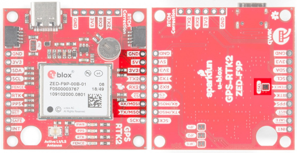
Qwiic MP3 Trigger Hookup Guide

$
0
0

Qwiic MP3 Trigger Hookup Guide a learn.sparkfun.com tutorial

Available online at: http://sfe.io/t859

Introduction

Sometimes you just need to play an MP3 file. Whether it's a sound track as you enter the room or a pirate cackling when a dollar gets donated to the kid's museum. The Qwiic MP3 Trigger takes care of all the necessary bits, all you need to do is send a simple I2C command and listen.

SparkFun Qwiic MP3 Trigger

SparkFun Qwiic MP3 Trigger

DEV-15165
$19.95

Required Materials

The Qwiic MP3 Trigger does need a few additional items for you to get started, shown below. However, you may already have a few of these items, so feel free to modify your cart as necessary.

USB 2.0 Cable A to C - 3 Foot

USB 2.0 Cable A to C - 3 Foot

CAB-15092
$3.95
Hamburger Mini Speaker

Hamburger Mini Speaker

COM-14023
$4.95
2
USB Wall Charger - 5V, 1A (Black)

USB Wall Charger - 5V, 1A (Black)

TOL-11456
$3.95
2
microSD Card - 1GB (Class 4)

microSD Card - 1GB (Class 4)

COM-15107
$4.95
Note: If you want to add hardware connections for the triggers, you will probably some soldering equipment, hook-up wire, and some momentary buttons. Additionally, if you wish to interface with the board using a microcontroller, you should also grab a RedBoard Qwiic and some Qwiic cables.

Suggested Reading

If you’re unfamiliar with switches, jumper pads, or I2C be sure to checkout some of these foundational tutorials.

Switch Basics

A tutorial on electronics' most overlooked and underappreciated component: the switch! Here we explain the difference between momentary and maintained switches and what all those acronyms (NO, NC, SPDT, SPST, ...) stand for.

I2C

An introduction to I2C, one of the main embedded communications protocols in use today.

How to Work with Jumper Pads and PCB Traces

Handling PCB jumper pads and traces is an essential skill. Learn how to cut a PCB trace, add a solder jumper between pads to reroute connections, and repair a trace with the green wire method if a trace is damaged.

If you aren't familiar with the Qwiic system, we recommend reading here for an overview if you decide to use an Arduino to control the Qwiic MP3 Trigger via I2C.

Qwiic Connect System

Hardware Overview

Electrical Characteristics

The Qwiic MP3 Trigger is designed to operate at 3.3V and must not be powered above 3.6V as this is the maximum operating voltage of microSD cards. The 5V power from the USB C connector tied to a robust AP2112 3.3V voltage regulator that can source up to 600mA for the board. Otherwise, the board can also be powered through the Qwiic connector.

Maximum Operating Voltages

All I/O pins are 5V tolerant but the board must but powered at 3.3V.

Recommended Operating Voltages

All I/O pins are designed to function at 3.3V. The board consumes 35mA at 3.3V in standby and can consume over 400mA when driving at 8 Ohm speaker at max volume.

Note: The Qwiic MP3 Trigger can be powered through either the USB C cable or the Qwiic connector when used in conjunction with the RedBoard Qwiic. However, when using the Qwiic connection make sure that the 3.3V line can source enough current for the amplifier.

MP3 and ATtiny84

At the heart of the Qwiic MP3 Trigger is the WT2003S MP3 decoder IC. This IC reads MP3s from the microSD card and will automatically mount the SD card as a jump drive if USB is detected. The ATtiny84A receives I2C commands and controls the MP3 decoder.

WT2003S IC and ATtiny84A IC

SD and USB

The SparkFun Qwiic MP3 Trigger works with 512MB to 32GB cards formatted in FAT32. We recommend the SparkFun 1GB MicroSD Card because it’s a good mix of low-cost and good performance for MP3 playing.

The USB C and microSD connectors on the SparkFun Qwiic MP3 Trigger

The easiest way to add and remove MP3s to the Qwiic MP3 Trigger is to attach a USB C cable. This will enumerate the microSD card as a jump drive making it extremely easy to access the files on the card. Alternatively, if you don’t want to use USB, you can eject the microSD card and read/write to it using a normal USB SD adapter.

Qwiic Connectors

The Qwiic MP3 Trigger from SparkFun includes two Qwiic connectors to make daisy chaining this music player with a large variety of I2C devices. Checkout Qwiic for your next project.

Highlighted I2C port and Qwiic connectors

The I2C pins broken out on the board are tied directly to the Qwiic connectors.

Audio Amplifier

The speaker is boosted by a Class-D mono amplifier capable of outputting up to 1.4W. What does 1.4W mean? It's incredibly loud; great for making sure your mech effects are heard on the *con floor (i.e. _Comic_ - con, _Def_ - con, etc.) and wonderful for annoying your officemates. Both outputs have volume controlled by the SET_VOLUME command and is selectable between 32 levels. Additionally, there are PTH holes beside both connectors if a soldered connection is preferred.

Class D Amplifier on SparkFun Qwiic MP3 Trigger
Note: The volume can be adjusted in software using the SET_VOLUME0x07 command (see Command Set section). The volume setting is saved to NVM (non-volatile memory) and loaded at power on.

Audio Outputs

A standard 3.5mm audio jack is provided making it easy to play your tunes over headphones or amplified desktop speakers like our Hamburger Speaker or any other amplifier.

3.5mm audio jack and poke-home connectors

A poke-home connector labeled Speaker is also provided in parallel to the 3.5mm jack. This is a friction fit type connector; simply push stranded or solid core wire (22AWG or larger) into the hole and the connector will grip the wire.

To use an external speaker, solder two wires onto the speaker and insert the wires into the poke home connector.

Inserting tinned speaker wires into the Qwiic MP3 Trigger

Wire inserted into the poke home connector.

To remove, push down on the tab with a ballpoint pen and gently pull on the wire.

Using pen to remove wire from poke home connector

Using pen to remove wire from poke home connector.

Jumpers

The Qwiic MP3 Trigger has three jumpers shown below:

Three jumpers on the SparkFun Qwiic MP3 Trigger

The default 7-bit I2C address of the Qwiic MP3 Trigger is 0x37. The ADR jumper is open be default and can be closed with solder to force the device’s I2C address to 0x36. This is handy if you need to have two Triggers on the same bus. If you need more than two devices on the bus, or if these addresses conflict with another I2C device the address can be changed in software. Please see the Command Set.

Cutting the I2C jumper will remove the 2.2k Ohm resistors from the I2C bus. If you have many devices on your I2C bus you may want to remove these jumpers. Not sure how to cut a jumper? Read here!

The INT jumper is located below the SparkFun logo and connects a 10K pull-up resistor to the INT pin. If you have multiple, open-drain, interrupt pins connected together you may want to remove this pull-up to better control the pull-up resistance.

I/O Pins

There are several I/O pins broken out on the board, which are described in the table below.

Pins on the Qwiic MP3 Player
Pin NameTypeDescription
RSTInputActive low. Pull this pin low to reset the ATtiny84A, effectively resetting the Qwiic MP3 Trigger.
INTOutputActive low. Goes low when track is finished playing. Goes high again when CLEAR_INTERRUPTS command is issued.
SCLInputSerial clock line of I2C interface. Qwiic MP3 Trigger does implement clock stretching and will hold the clock line low if it is unable to receive additional I2C data.
SDAInput/OutputSerial data line of I2C interface.
3.3VPowerQwiic MP3 Trigger can be powered from 2.8V to 3.3V. Anything greater than 3.6V will damage the microSD card.
GNDPowerThe ground pin.
Trigger 1-4InputWhen a trigger pin is pulled to ground, the corresponding T00X.mp3 file is played. Pins can be combined to play T001 to T010. Pins are 5V tolerant.

Triggers

There are four trigger pins at the top of the board. When pulled low these pins begin playing whatever file is named T001.mp3 to T010.mp3. For example, if you attach a momentary button to Pin 3 and GND, when you press that button the T003.mp3 file will immediately be played. This allows you to start playing sound effects with the touch of a button without any programming!

Four trigger pins at the top of Qwiic MP3 Trigger
Single Trigger

For a basic triggered setup, load four files named T001.mp3, T002.mp3, T003.mp3, and T004.mp3 on the microSD card. Use a wire or button to connect a trigger pin to ground and the associated track will begin playing. Once you have the setup working, use any momentary button to allow a user to cause an MP3 to start playing.

Using Multiple Triggers

By pulling multiple pins down simultaneously the four triggers can play up to ten tracks: T001 to T010. When a trigger pin is detected the pin values are added together. For example, pulling pins 2 and 4 low at the same time will play track T006.mp3 as will pulling pins 1, 2, and 3 low at the same time.

Interrupt Pin

The Qwiic MP3 Trigger has an INT pin which is configured as an open-drain pin with an on board 10K Ohm pull-up.

INT pin and jumper

The INT pin will go low when a track has stopped playing. Once the CLEAR_INTERRUPTS0x0D command has been received, the INT pin will become high-impedance and will return to a high level.

If you have multiple devices with bussed interrupt pins you may want to cut the INT jumper to remove the 10K pull-up resistor.

Qwiic MP3 Trigger Library

Note: This section assumes you are using the latest version of the Arduino IDE on your desktop. If this is your first time using Arduino, please review our tutorial on installing the Arduino IDE. If you have not previously installed an Arduino library, please check out our installation guide.

The SparkFun Qwiic MP3 Trigger Arduino library demonstrates how to control all the features of the Qwiic MP3 Trigger. We recommend downloading the SparkFun library through the Arduino library manager by searching 'SparkFun MP3 Trigger'. Alternatively you can grab the zip here from the GitHub repository:

Once you have the library installed checkout the various examples.

  • Example1: Play the first MP3 track on the microSD card.
  • Example2: Play the next track on the microSD card.
  • Example3: Play a particular file. For example mp3.playFile(3); will play F003.mp3.
  • Example4: Stop and pause tracks.
  • Example5: Kitchen sink example showing setting of volume, equalizer, get song name, get song count, get firmware version, etc.
  • Example6: Change the I2C address of the MP3 Trigger. Allows multiple Triggers to live on the same I2C bus.
  • Example7: Shows how to start the library using a different Wire port (for example Wire1).
  • Example8: Demonstrates how to check for the end-of-song interrupt and begin playing the song again.

Command Set

The SparkFun Qwiic MP3 Trigger library takes care of all these commands for you. However, if you want to implement your own interface, the following commands are available (see list below). The Qwiic MP3 Trigger uses standard I2C communication to receive commands and send responses. By default, the unshifted I2C address of the Qwiic MP3 Trigger is 0x37. The write byte is 0x6E and the read byte is 0x6F.

Here is an example I2C transaction showing how to set the volume level to 10:

Logic trace showing 0x6E 0x07 0x0A

Here is an example I2C transaction showing how to read the device ID (0x39):

Logic trace showing 0x6E 0x10 0x6F 0x39

The following commands are available:

  • STOP0x00 - Stops any currently playing track
  • PLAY_TRACK0x01 [TRACKNUMBER] - Play a given track number. For example 0x01 0x0A will play the 10th MP3 file in the root directory.
  • PLAY_FILENUMBER0x02 [FILENUMBER] - Play a file # from the root directory. For example 0x02 0x03 will play F003.mp3.
  • PAUSE0x03 - Pause if playing, or starting playing if paused
  • PLAY_NEXT0x04 - Play the next file (next track) located in the root directory
  • PLAY_PREVIOUS0x05 - Play the previous file (previous track) located in the root directory
  • SET_EQ0x06 [EQ_SETTING] - Set the equalization level to one of 6 settings: 0 = Normal, 1 = Pop, 2 = Rock, 3 = Jazz, 4 = Classical, 5 = Bass. Setting is stored to NVM and is loaded at each power-on.
  • SET_VOLUME0x07 [VOLUME_LEVEL] - Set volume level to one of 32 settings: 0 = Off, 31 = Max volume. Setting is stored to NVM and is loaded at each power-on.
  • GET_SONG_COUNT0x08 - Returns one byte representing the number of MP3s found on the microSD card. 255 max. Note: Song count is established at power-on. After loading files on the SD card via USB be sure to power-cycle the board to update this value.
  • GET_SONG_NAME0x09 - Returns the first 8 characters of the file currently being played. Once the command is issued the MP3 Trigger must be given 50ms to acquire the song name before it can be queried with an I2C read.
  • GET_PLAY_STATUS0x0A - Returns a byte indicating MP3 player status. 0 = OK, 1 = Fail, 2 = No such file, 5 = SD Error.
  • GET_CARD_STATUS0x0B - Returns a byte indicating card status. 0 = OK, 5 = SD Error. Once the command is issued the MP3 Trigger must be given 50ms to acquire the card status before it can be queried with an I2C read.
  • GET_VERSION0x0C - Returns two bytes indicating Major and Minor firmware version.
  • CLEAR_INTERRUPTS0x0D - Clears the interrupt bit.
  • GET_VOLUME0x0E - Returns byte that represents the volume level.
  • GET_EQ0x0F - Returns byte that represents the EQ setting.
  • GET_ID0x10 - Returns 0x39. Useful for testing if a device at a given I2C address is indeed an MP3 Trigger.
  • SET_ADDRESS0xC7 [NEW_ADDRESS] - Sets the I2C address of Qwiic MP3 Trigger. For example 0x6E 0xC7 0x21 will change the MP3 Trigger at I2C address 0x37 to address 0x21. In this example 0x6E is device address 0x37 with write bit set to 1. Valid addresses are 0x08 to 0x77 inclusive. Setting is stored to NVM and is loaded at each power-on.

Command Que

The ATtiny84A receives commands over I2C. It then records the I2C commands into a command que. The que is sent FIFO over serial to the WT2003S at 9600bps. The WT2003S then requires an undetermined amount of time to respond. This means that commands are not instantaneously executed by the Qwiic MP3 Trigger and some commands may require a certain amount of time to before the Qwiic MP3 Trigger has loaded a valid response.

I2C traces showing how to read a song name

An Example GET_SONG_NAME. Do you know the answer?

For example, GET_SONG_NAME can be issued by the master microcontroller to the Qwiic MP3 Trigger. The QMP3 then transmits a serial command to the WT2003S. After a certain amount of time (unfortunately there are no max times defined by the WT2003S datasheet) the WT2003S will respond via serial. This can take 15 to 40ms. At that time, the song name will be loaded onto the Qwiic MP3 Trigger and can be read over I2C by the master microcontroller.

In order to avoid clock stretching by the Qwiic MP3 Trigger and tying up the I2C bus, the Qwiic MP3 Trigger will release the bus after every command is received. Therefore, it is up to the user to wait the minimum 50ms between the WRITE GET_SONG_NAME and the READ I2C commands.

Power Up Time

The MP3 decoder IC on the Qwiic MP3 Trigger is the WT2003S. It requires approximately 1500ms after power on to mount the SD card. Normally, the Qwiic MP3 Trigger is powered while the user writes and re-writes sketches so the user does not notice this boot time. The boot time only comes into effect when user initially powers their project. The main controller (such as an Uno) needs to wait up to 2 seconds before giving up communicating with the Qwiic MP3 Trigger. The SparkFun Qwiic MP3 Trigger library takes care of the 2 second wait but if you’re writing your own implementation then consider the following example code:

language:c
if (isConnected() == false)
{
    delay(2000); //Device may take up to 1500ms to mount the SD card

    //Try again
    if (isConnected() == false)
        return (false); //No device detected
}
return (true); //We're all setup!

Example 1: Play Track 1

The Qwiic MP3 Trigger can be used both as a standalone board or with the Qwiic connect system. In this case, we will be using the RedBoard Qwiic as the microcontroller in the Qwiic system.

For both options, make sure to load an MP3 file labeled T001.mp3 onto the MicroSD card.

Standalone: Using Trigger 1

By default the firmware installed on the ATtiny84 allows you to play tracks using the triggers. For more details, see the Triggers section of the Hardware Overview. Simply plug in the SD card, power the Qwiic MP3 Trigger, and short the Trigger Pin 1 to GND. Everytime you short both pins, T001.mp3 will play.

Using trigger pins

Triggering the first track to play by shorting Trigger 1 with a pair tweezers. Click on image for a closer view of the hardware setup.

Arduino Library: Using RedBoard Qwiic

Plug in the SD card into the MP3 Trigger. Then, connect the Qwiic MP3 Trigger to the RedBoard Qwiic using a Qwiic cable.

Triggering with a RedBoard

Triggering the first track to play through the Qwiic connection. Click on image for a closer view of the hardware setup.

Upload Example1-PlaySong.ino using the Arduino IDE to the RedBoard Qwiic. Once uploaded, the RedBoard will check for the Qwiic MP3 Trigger, set the volume to 10 and then play T001.mp3. Pressing the RESET button on the RedBoard will run the sketch again.

Resources and Going Further

Have fun with your new tunes maker!

For more on the Qwiic MP3 Trigger, check out the links below:

Need some inspiration? Check out some of these related tutorials:

MP3 Player Shield Music Box

Music Box Project based on the Dr. Who TARDIS.

Sound Page Guide

How to use the Lilypad MP3 Player and some Bare Conductive Paint to make a fandom silhouette sound trigger page.

Photon Battery Shield Hookup Guide

The Photon Battery Shield has everything your Photon needs to run off, charge, and monitor a LiPo battery. Read through this hookup guide to get started using it.

Check out these other Qwiic tutorials:

Qwiic Differential I2C Bus Extender (PCA9615) Hookup Guide

Learn how to extend the range of your I2C communication bus with the Qwiic differential I2C bus extender (PCA9615 ) breakout board.

ESP32 LoRa 1-CH Gateway, LoRaWAN, and the Things Network

Using the ESP32 LoRa 1-CH Gateway as a gateway and device, and pushing data to The Things Network.

Qwiic UV Sensor (VEML6075) Hookup Guide

Learn how to connect your VEML6075 UV Sensor and figure out just when you should put some sunscreen on.
New!

Qwiic MP3 Trigger Hookup Guide

Playing MP3s has never been easier.

Or check out this blog post:


learn.sparkfun.com | CC BY-SA 3.0 | SparkFun Electronics | Niwot, Colorado
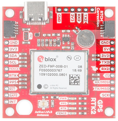
Viewing all 1123 articles
Browse latest View live


<script src="https://jsc.adskeeper.com/r/s/rssing.com.1596347.js" async> </script>