Quantcast
Channel: SparkFun Tutorials
Viewing all 1123 articles
Browse latest View live

Thumb Joystick Hookup Guide

$
0
0

Thumb Joystick Hookup Guide a learn.sparkfun.com tutorial

Available online at: http://sfe.io/t870

Introduction

Whether you're blasting aliens, driving a robot, or write your awesome classic Arcade Game for your Arduino, you'll find the analog thumb joystick a very useful addition to your projects. This tutorial will go over the analog thumb joystick breakout board with some Arduino examples.

SparkFun Thumb Joystick Breakout

SparkFun Thumb Joystick Breakout

BOB-09110
$1.95
7
Thumb Joystick

Thumb Joystick

COM-09032
$3.95
5

Later, we'll also go over the thumb joystick shield for Arduino and Processing examples. You can follow along with the examples using the breakout board if you have some additional hardware!

SparkFun Joystick Shield Kit

SparkFun Joystick Shield Kit

DEV-09760
$14.95
3

Suggested Viewing

For a simple demo of the thumb joystick, check out the video below!

Required Materials

To follow along with this tutorial, you will need the following materials. You may not need everything though depending on what you have. Add it to your cart, read through the guide, and adjust the cart as necessary.

SparkFun RedBoard - Programmed with Arduino

SparkFun RedBoard - Programmed with Arduino

DEV-13975
$19.95
39
Break Away Headers - Straight

Break Away Headers - Straight

PRT-00116
$1.50
20
SparkFun USB Mini-B Cable - 6 Foot

SparkFun USB Mini-B Cable - 6 Foot

CAB-11301
$3.95
2
Thumb Joystick

Thumb Joystick

COM-09032
$3.95
5
Jumper Wires Premium 6" M/M Pack of 10

Jumper Wires Premium 6" M/M Pack of 10

PRT-08431
$3.95
2
SparkFun Thumb Joystick Breakout

SparkFun Thumb Joystick Breakout

BOB-09110
$1.95
7
Breadboard - Mini Modular (Green)

Breadboard - Mini Modular (Green)

PRT-12046
$3.95
1

Tools

You will need a soldering iron, solder, and general soldering accessories.

Break Away Headers - Straight

Break Away Headers - Straight

PRT-00116
$1.50
20
Third Hand

Third Hand

TOL-09317
$9.95
9
Soldering Iron - 60W (Adjustable Temperature)

Soldering Iron - 60W (Adjustable Temperature)

TOL-14456
$12.95
7
Solder Lead Free - 15-gram Tube

Solder Lead Free - 15-gram Tube

TOL-09163
$3.50
2
Needle Nose Pliers

Needle Nose Pliers

TOL-08793
$1.95
1
Panavise Jr. - Vacuum Base

Panavise Jr. - Vacuum Base

TOL-10410
$32.95

Suggested Reading

If you aren’t familiar with the following concepts, we recommend checking out these tutorials before continuing.

How to Solder: Through-Hole Soldering

This tutorial covers everything you need to know about through-hole soldering.

Analog to Digital Conversion

The world is analog. Use analog to digital conversion to help digital devices interpret the world.

What is an Arduino?

What is this 'Arduino' thing anyway?

Installing Arduino IDE

A step-by-step guide to installing and testing the Arduino software on Windows, Mac, and Linux.

Connecting Arduino to Processing

Send serial data from Arduino to Processing and back - even at the same time!

How Does an Analog Thumb Joystick Work?

Imagine a volume control or other knob. These controls are generally made from potentiometers, which are variable resistors. By connecting the potentiometer as a voltage divider, you can get a varying voltage out of the device, which can be fed to an analog to digital converter on a microprocessor. This allows the software to read the knob position.

Potentiometers

This joystick contains two potentiometers, connected with a gymbal mechanism that separates the "horizontal" and "vertical" movements. (If the joystick is flat on a table, these movements are more "front / back" and "left / right", but you get the idea.) The potentiometers are the two blue boxes on the sides of the joystick. If you move the joystick while watching the center shaft of each potentiometer, you'll see that each of the potentiometers pick up movement in only one direction. Clever, isn't it!

Momentary Push Button

This joystick also contains a switch which activates when you push down on the cap. The switch is the small black box on the rear of the joystick. If you push down on the cap, you can see a lever pushing down on the head of the switch. The lever works no matter what position the joystick is in. Cool!

Hardware Overview: Breakout

The breakout board has 5 pins broken out to easily connect to the thumb joystick. When mounting and programming with the joystick, make sure to keep track of the orientation of the board to determine what position the joystick is in.

Thumb Joystick Breakout Board Top View
  • VCC - Connect this to your positive supply (usually 5V or 3.3V depending on your logoc levels).
  • VERT - This is the vertical output voltage (will be about half of VCC when the joystick is centered).
  • HORIZ - This is the horizontal output voltage (will be about half of VCC when the joystick is centered).
  • SEL - This is the output from the pushbutton, normally open, will connect to GND when the button is pushed.
  • GND - Connect this to your ground line (GND).

Hardware Assembly: Breakout

To easily connect to the joystick, you'll need a "breakout board" (the red printed-circuit board, or PCB). You'll need to solder the breakout board to the joystick. If this is your first time soldering you'll probably want to check out our introductory soldering tutorial first. Read the guide and you'll pick up some good tips that will help your first soldering experience go more smoothly.

How to Solder: Through-Hole Soldering

September 19, 2013

This tutorial covers everything you need to know about through-hole soldering.

Once this is done, it will be much easier to connect the joystick to your project (you won't have to solder wires to all those little pins). To attach the breakout board to the joystick, follow these steps.

Insert Thumb Joystick to Breakout Board

First, test-fit the breakout board to the joystick. If any pins on the joystick are bent, gently straighten them. The joystick goes into the side of the board with the white outline (not the side with the SparkFun logo). Insert the joystick into the board, matching the white outline, and ensure that all the pins go into their holes (if they don't, you may not have the joystick oriented correctly).

alt text

Solder

If everything fits OK, carefully solder the pins from the opposite side of the board (the side with the SparkFun logo). Never soldered before? It's easy, check out our tutorial on how to solder. If this is your first time soldering, practice a bit before working on this board. Before and during soldering, ensure that the joystick stays tight against the breakout board. There are 14 solder connections to make, including the four posts at the corners of the joystick.

Solder All Pins to the Breakout Board

If you'd like to connect a 5-pin header to the board, or solder bare wires to the output holes, you may do that now.

Solder Headers to Pins Broken Out

Once you're done soldering, you're ready to use your joystick! If you have not already, insert the cap on the joystick.

Soldered Thumb Joystick

Arduino Examples: Breakout

Hardware Hookup

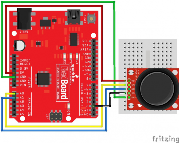
The breakout board provides five labeled connections. You'll connect these lines to your project or microcontroller. In this example, we'll use the RedBoard with ATmega328P. For stability, make sure to have part of the breadboard under the joystick.

Thumb Joystick Circuit Arduino

Hookup Table

RedBoard w/ Atmega328P Thumb Joystick Breakout
5V VCC
A0 VER
A1 HOR
2 SEL
GND GND

Thumb Joystick Breakout Board Example

Note: This example assumes you are using the latest version of the Arduino IDE on your desktop. If this is your first time using Arduino, please review our tutorial on installing the Arduino IDE.

Here's an example Arduino sketch which sets up the microcontroller to read the inputs, and then continuously prints the values to the serial monitor. If you're using a different microcontroller, the steps should be similar; you'll just need to determine how to read analog and digital inputs on your device. Copy the code and paste it in the Arduino IDE. Select Arduino/Genuino Uno as the board, the COM port that it enumerated on, and hit the upload button.

language:c
// Thumb Joystick Breakout Board Example
// Modified by: Ho Yun "Bobby" Chan, SparkFun Electronics, 2/19
// Written by: Mike Grusin, SparkFun Electronics 3/11
// This code is free, baby. Use it however you like.

// This sketch shows the basic operation of the Thumb Joystick (COM-09032) and breakout board (BOB-09110).
// The joystick outputs two analog voltages (VERT and HORIZ), and one digital signal (SEL) for the pushbutton.

// Connections to joystick (change if you use different pins):

const int VERT = 0; // analog
const int HORIZ = 1; // analog
const int SEL = 2; // digital

// Also connect the joystick VCC to Arduino 5V, and joystick GND to Arduino GND.

// This sketch outputs serial data at 9600 baud (open Serial Monitor to view).

//initialize variables for analog and digital values
int vertical, horizontal, select;

void setup(){
  /* old method to turn on the pull-up resistor for the SEL line
     before Arduino IDE v1.01 (see http://arduino.cc/en/Tutorial/DigitalPins)
     make the SEL line an input*/
  //pinMode(SEL, INPUT);
  //digitalWrite(SEL, HIGH);

// make the SEL line an input
  pinMode(SEL, INPUT_PULLUP);

  // set up serial port for output
  Serial.begin(9600);
}

void loop(){

  // read all values from the joystick

  vertical = analogRead(VERT); // will be 0-1023
  horizontal = analogRead(HORIZ); // will be 0-1023
  select = digitalRead(SEL); // will be HIGH (1) if not pressed, and LOW (0) if pressed

  // print out the values

  Serial.print("vertical: ");
  Serial.print(vertical, DEC);
  Serial.print(" horizontal: ");
  Serial.print(horizontal, DEC);
  Serial.print(" select: ");
  if (select == HIGH) {
    Serial.println("not pressed");
  }
  else {
    Serial.println("PRESSED!");
  }
}

What You Should See

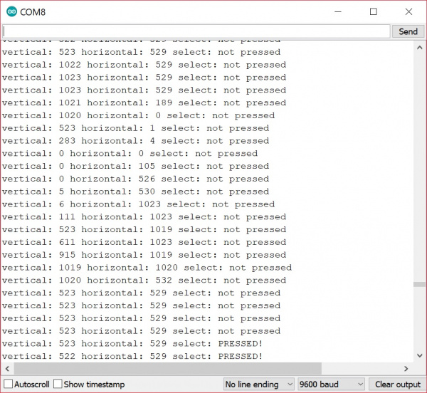
Open the serial monitor at 9600 baud to begin seeing the raw output values. With the vertical "↑ V" pointing away from you, start moving the joystick around.

Example Raw Output

In this case, the joystick was sitting around 520 for the vertical and horizontal values when not moving. Moving the joystick up toward the up arrow and in a clockwise motion, the joystick will read a value of about 1023 for the vertical component while the horizontal sits at the same value. Moving it to the right, the vertical component will sit at the resting value of about 520 again while the horizontal component will read a value of about 0. As the joystick moves down toward you, you'll notice the vertical component will drop to 0 and the horizontal will sit at it's resting value again. Moving the joystick to the left, you'll noitice the vertical component sit back to its resting value while the horizontal component jump up to 1023. Finally, you'l receive a the "PRESSED!" message when pressing down on the joystick.

Looking for more examples with the joystick? Check out the examples in the next section for the shield!

Hardware Overview: Shield

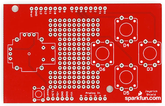
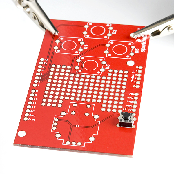
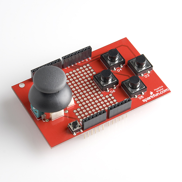
Below is a top view of the shield before any component is soldered.

Thumb Joystick Top View
  • Joystick - On the left of the board is the footprint for the thumb joystick. The potentiometers are connected to analog pins A0 and A1. The "select" button for the joystick is connect is connected to pin 2.

  • Prototyping Area - The center includes general plated through holes to prototype and solder additional components like a small OLED screen, XBee Explorer, or sensors. You'll need to wire it up to the respective pins depending on your project.

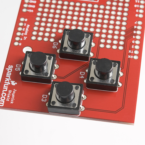
  • 12mm Buttons - On the right are locations for four 12mm momentary pushbuttons. Up is connected to pin 4, right to pin 3, down to pin 5, and left to pin 6.

  • Edge Pins - The board was designed for the original Arduino Uno footprint so you'll see the standard headers on the edge of the board.

  • Reset Button - Just beside the reset pin is the location for the mini push button to reset an Arduino when stacked on top.

Hardware Assembly: Shield

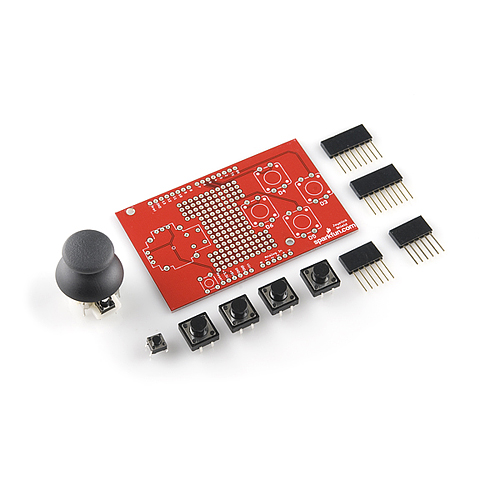
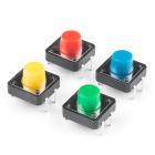
Before assembling the shield, make sure that you have all the components needed to solder the board together.

alt text

If you ordered a kit, you should have the following components included.

All parts present and accounted for? Great, let's start to put the shield together.

Insert Thumb Joystick and Buttons to Shield

Before I start to solder parts into place, I like to do a "test fit" of the kit components. This allows me to check that everything fits as expected plus it's fun. Just work through the rest of these instructions carefully putting the components into place but don't solder anything. This is entirely optional.

Once you've done a test fit, you can pull the components out with care and then put the shield together for real!

Soldering Tips

If this is your first time soldering you'll probably want to check out our introductory soldering tutorial first. Read the guide and you'll pick up some good tips that will help your first soldering experience go more smoothly.

How to Solder: Through-Hole Soldering

September 19, 2013

This tutorial covers everything you need to know about through-hole soldering.

Below you'll find a suggested order for assembling the shield, your personal preference might give you other ideas on how to proceed and that's fine too. When no order for assembling is provided, soldering the smallest components in first is a good rule to follow. Just make sure all the pieces go in the right place and in the correct orientation.

If you don't have a PCB vise then you might want to put the header pins in before the thumb joystick — that way you can rest the PCB on the headers as you solder the pins. (In fact, you might want to do this even if you do have a vise.)

Another approach to consider is to attach the headers first so you can test each component is working after you add it.

Alright, let's start with...

Mini Push Button Switch

The mini push button resets the main Arduino board — it's present because once the shield is connected to the Arduino, it's difficult to access the normal reset button.

Ensure you're looking at the top of the PCB — the top is where the components sit — it will have the "sparkfun.com" text and logo on it.

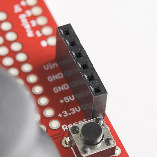
Begin by pushing the four legs (or leads) of the button into the correct location on the PCB as shown in the photograph below. It sits just below the word "Reset" on the PCB. The button can be orientated in four different directions with the legs pointing down but only two of them are correct — you shouldn't need to apply much force to seat the push button in the holes. See the next closeup image for a better view of how the button should sit.

alt text

You can see more clearly below that the legs splay out slightly. There's two pairs of legs on opposite sides of the body — one pair should sit in the set of holes close to the edge of the PCB while the other pair should sit on the opposite short-edge side of the white rectangle marked ("silk screened") on the PCB.

If you bend one of the legs too much gently move it back into place — but don't do this too often or the metal will break from metal fatigue.

With enough room below the PCB for the legs to extend apply pressure to the top of the push button so the plastic bottom sits on the PCB — this allows the PCB to take most of the force when you press the button rather than the thin metal legs.

alt text

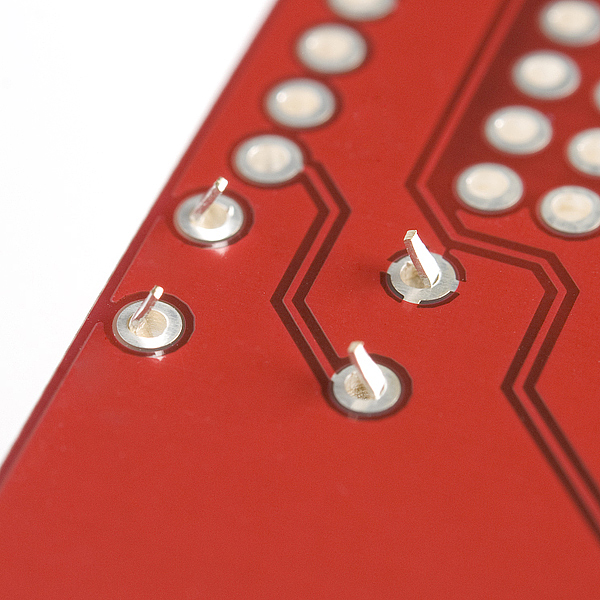
Next turn the board over and you should see those cute little legs pointing through the holes in the PCB. If they don't extend as far as shown in this picture check you have the orientation correct and then apply a little more pressure to pop the legs through. The button shouldn't fall out of the holes when you turn the PCB upside down.

alt text

Now it's time to solder the first leg — it doesn't matter which of the four you start with — but ensure the plastic bottom of the button is still flat against the PCB. Apply heat with the soldering iron simultaneously to the leg of the button and the pad (the circle of track around the hole) on the PCB then carefully feed a little piece of the solder into the joint formed between the soldering iron, pad, and component leg. Then remove the solder wire and then the soldering iron — in that order.

Once you have completed one leg, again check the bottom of the button is touching the PCB and then solder the diagonally opposite leg as well. Soldering the legs in this order ensures the button sits well and you can solder the two remaining legs without needing to double-check if the button is still sitting correctly.

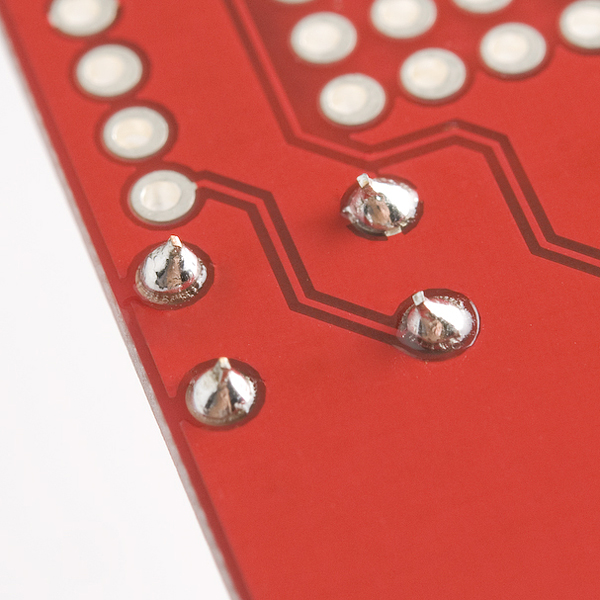
When you have soldered all four legs of the button it should look something like the photo below:

alt text

If you like, you can flip the board back over and give the mini push button a triumphant press and show it to your friends.

Push Buttons

It is now time to attach the four larger push buttons to the shield. These are the "action" buttons of your joystick shield and you can use them to control the actions of a character on screen, perhaps causing the character to shoot, punch or arrange flowers as the mood strikes. ("Flower Arranger II : This time it's Perennial!")

You'll notice the method we use is very similar to the approach we took with the mini push button — this is because the buttons are almost identical in construction apart from their size.

First, insert the legs of the four buttons into the holes on the PCB — their orientation should mean the edges without legs cover the white silk screen lines above and below the white silk screen circles. For each button ensure all four legs are inside their respective holes before applying pressure to the top of the button to push the legs through to the other side — if you're not careful you can bend one or more of the legs under the button by accident. If you do bend one of the legs under, remove the button and use a small screwdriver or pair of pliers to straighten the bent leg enough that it will again sit in the correct place to fit through the hole.

I suggest putting all four buttons into place before soldering them because the legs will prevent them from falling out when you flip the board over and it's nice to be able to get into the flow of things and solder all the joints at one time. But if you prefer to solder each button in place before adding the next that should work okay too.

alt text

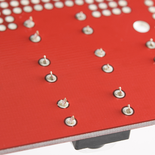
You can now flip the board over and see the push button legs all poking through in a manner resembling the view of the pool during a synchronized swimming competition.

alt text

Once again it's time to solder the first of the button legs. My suggestion is to start with the button closest to the middle of the board and work left to right and down from there so you don't have to move the soldering iron over already soldered joints. Again the order isn't critical though.

As before, it doesn't matter which of the four legs of the button you start to solder — but remember to ensure the plastic bottom of the button is still flat against the PCB. You may have to hold the buttons from underneath against the PCB as the legs might be a little loose, be sure to touch only the plastic part as the metal part will heat up. Apply the heat with the soldering iron simultaneously to the leg of the button and the pad then carefully feed a little piece of the solder roll into the joint formed between the soldering iron, pad, and component leg. Then remove the solder wire and then the soldering iron — in that order.

Once you have completed one leg, again check if the bottom of the button is touching the PCB and then solder the diagonally opposite leg as well. Soldering the legs in this order ensures the button sits well and you can solder the two remaining legs without needing to double-check if the button is still sitting correctly.

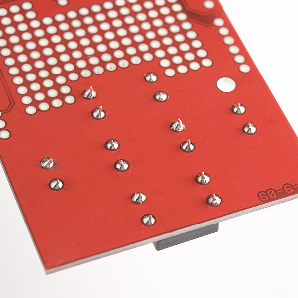
After you've finished all sixteen legs the board should look like this — I hope those swimmers weren't planning on leaving the pool today:

alt text

Thumb Joystick

As you may recall from the introduction to this soldering section I suggest you learn from my experience (especially if you don't have a PCB vise) and solder the headers before you solder the thumb joystick. If that's the case, feel free to skip ahead to the headers section and then return to this joystick section.

Ha, I can't believe they fell for that "solder the headers first" trick, can you? Well, joke's on you because it really is easier to solder the headers before the joystick but if you insist, here's how to get the joystick connected. Just remember if you have the headers connected then your board will look a little different to these photos.

You first need to insert the legs of the joystick into the board similar to the breakout board. There's quite a number of legs of different sizes so it pays to be careful pushing the joystick into place.

You'll notice there's a number of sets of legs:

  • Four legs for the small mini push button used for the center button functionality. This sits on an outcrop that juts out from one side of the white plastic base and will look suspiciously similar to our reset mini push button. These are quite thin legs.
  • Four legs which are thicker than the others and are located at the four corners of the main part of the white plastic base. These legs are structural only and aren't intended to connect to any electrical signals.
  • Two sets of three legs each connected to the green bodies of the potentiometers used to detect the joystick position in two dimensions.

You might find it easier to remove the black plastic top or "hat" from the joystick first like I have in these photos — just give the hat a gentle tug and it should slide off the center stick. Put the hat to one side so you don't lose it or see if you can wear it as a hat yourself in which case you probably will lose it.

The mini push button legs are the most difficult to get in the correct place so I suggest you line those ones up with the appropriate holes first. Note the whole joystick will only fit in one orientation which has the mini push button facing the center on the PCB. It might help to tilt the base of the joystick slightly so that the two structural legs closest the mini push button fit into their associated holes around the same time as the button legs are in the right place. Then tilt the base level so the remaining legs fit into their proper holes. It's like putting on trousers, there's few things more annoying than getting your leg in the wrong hole — so take your time to make sure everything's where it should be.

If you do bend a leg, first try to see if you can push it gently into position with the head of a small screwdriver, otherwise take the joystick out, straighten the leg and try again — but once again if you do this too often the leg might snap off from metal fatigue.

alt text

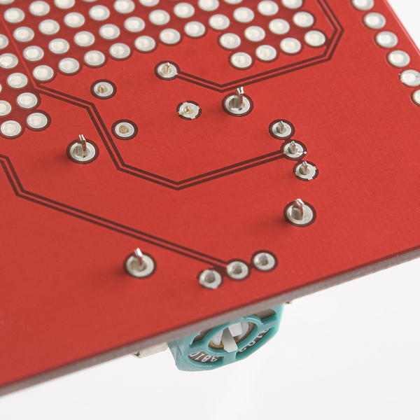
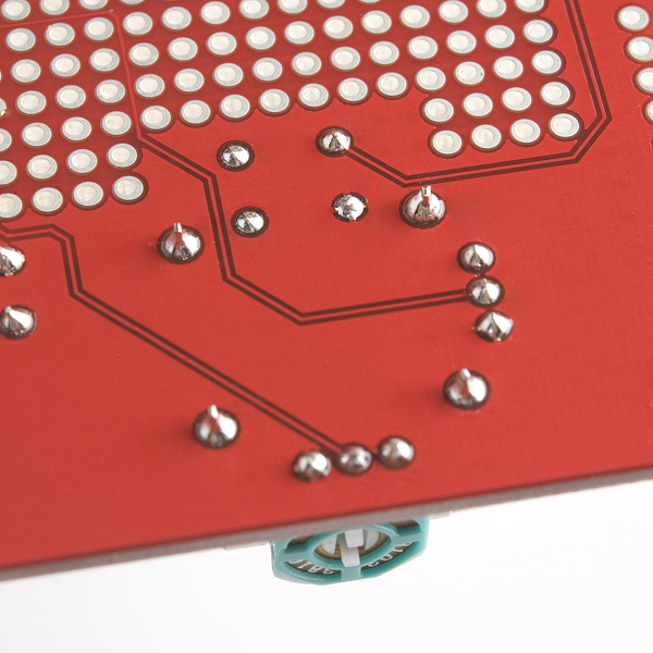
Once you've applied enough pressure to the top of the joystick case all the legs should poke through the bottom of the PCB — the structural legs will protrude further than the others:

alt text

You have a couple of options for the order in which you solder the legs but my suggestion is to start with the structural legs:

  • Ensure the base is sitting as close to the PCB as possible — it won't sit entirely flush as there are plastic bumps on the base that prevent this.
  • Then solder the four structural legs starting with any leg. You can use more solder than you might normally use to provide extra support.
  • Check the base is still somewhat flush.
  • Solder the diagonally opposite structural leg into place.
  • Then solder the two remaining structural legs in any order.
  • After the structural legs are in place, I'd suggest soldering the two sets of three potentiometer legs.

Finally, ensure the mini push button legs are through the PCB as far possible and solder the button in place in the same way you've done before.

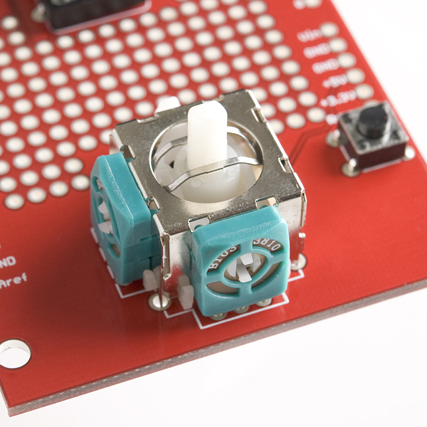
When you're finished your board should look somewhat like this:

alt text

If you've already attached the headers you can now flip the board over and reattach the plastic hat to the white center post of the joystick — take note that it will only fit in two orientations as the center post is rectangular. You can now skip to the Completed Solder Joints section.

If you still need to attach the headers you can move on to the next section.

Feel free to pretend you're using the joystick to dock the Apollo before you move on. ("Psssh" thruster noises aren't optional if you do though.)

alt text

Headers

Now it's time to solder the headers. You'll notice in these images and the parts list we use the stackable headers which allow an additional shield to be stacked on top of this one. The alert among you will notice however that a standard shield won't fit on top of this shield due to the position of the joystick and even if it did it would obscure at least one of the push buttons.

So what's the advantage of using the stackable headers in this case? It means you can still insert jumpers into the headers to gain access to the unused pins. If you wanted you could also add a custom mini shield on top if you'd like — perhaps with a couple of extra buttons?

If you don't think you'll need this extra functionality you can use standard breakaway headers instead. If you only populate the used pins with headers you can probably still insert jumpers into the other through the holes in the PCB if you need.

Six Pin Headers

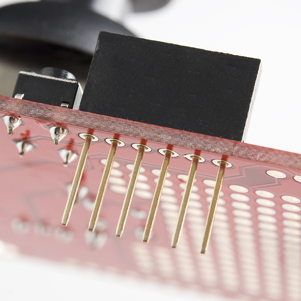
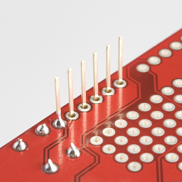
Let's start by soldering the two six pin headers that will supply power and access to the analog pins. First, you can insert one of the headers into the correct location like this:

alt text

If you don't have a PCB vise then you will probably want to temporarily put one of the 8 pin headers into its location so that the PCB is level when you solder the headers. The headers won't stay in place when you flip the board over so hold them in place when you turn the PCB over to leave the pins sticking upwards.

If you have a PCB vise you might want to hold the header in place like the following photo:

alt text

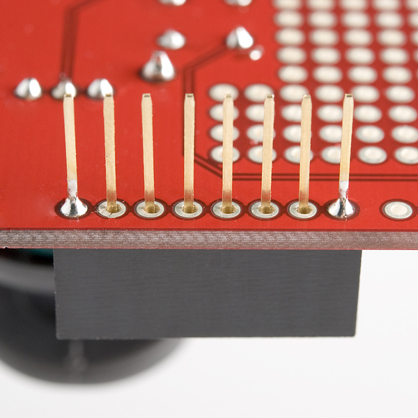
Next solder one of the pins into place. Ensure the header is aligned as parallel as possible to the edge of the board when you do this:

alt text

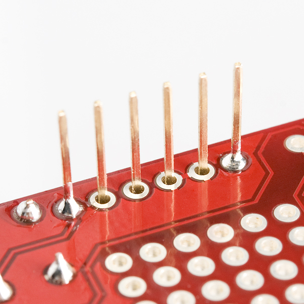
The reason we start with just one pin is because it makes it easier to obtain the correct alignment and fix any mistakes. Once you've soldered one pin, you might want to test the alignment by inserting the shield into an Arduino. Just be careful when you do so because the header's still only held in place with one solder joint.

If the alignment of the header isn't quite right, carefully reheat the solder joint and move the header slightly. Don't move it after you've removed the heat however, or you'll end up with a poor joint. Here is an example of checking the header alignment:

alt text

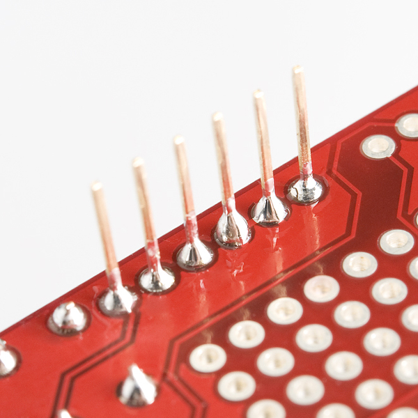
Once you're happy with the alignment of the header, you can solder another pin into place — my recommendation is to solder the pin at the opposite end of the header to the first pin you soldered. The reason for this is that once the two end pins are in place, the alignment won't change. I recommend double checking the alignment is still okay again by connecting it to your Arduino again.

Once again, if the alignment's not quite right you can reheat the joint and carefully move the pin.

alt text

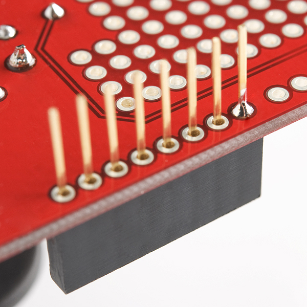
After you've confirmed the alignment you can solder the remaining four pins into place:

alt text

At this stage you can repeat these instructions for the second 6 pin header or skip ahead to solder the diagonally opposite 8 pin header. Soldering a 8 pin header now helps to get the alignment right.

Eight pin headers

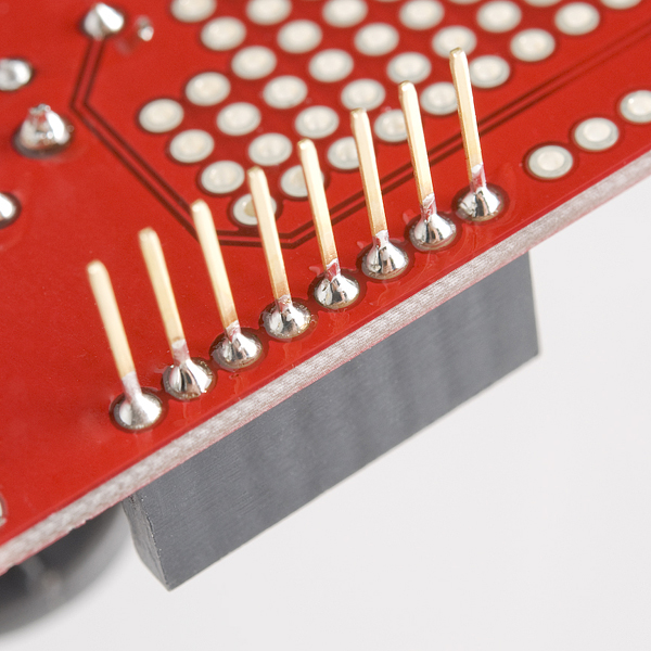
All right class, who can tell me how we're going to solder the 8 pin header..? Yes, you're correct, exactly the same as the 6 pin header except for the last step where we have an extra two pins to solder into place. As before, first we solder a pin at one end and check the alignment:

alt text

Then we solder the pin at the opposite end of the header and re-check the alignment:

alt text

And finally we solder the remainder of the pins in the middle of the header.

alt text

Repeat this for the second 8 pin header and you're done!

Don't forget to go back and solder the last 6 pin header if you skipped ahead. And if you still need to solder the joystick into place you can go back to that section.

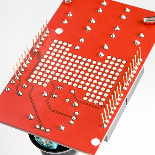
Completed Solder Joints

Once you've finished soldering all the components into place your board will look something like this:

alt text

Doesn't that red PCB look just spiffy?

Now's the time to double check all your soldering and fix up any problems:

  • Do the joints all look shiny and volcano shaped?
  • Do you have any "shorts" or "bridges" between joints where you've accidentally connected the two joints with solder? Check out the soldering guide for advice to avoid these problems.

Don't be too fussy though because re-heating and moving the joints is to be avoided if possible.

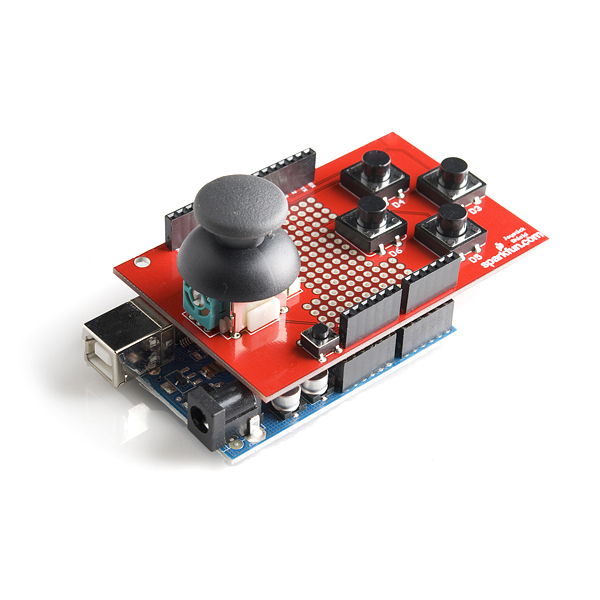
Completed Shield

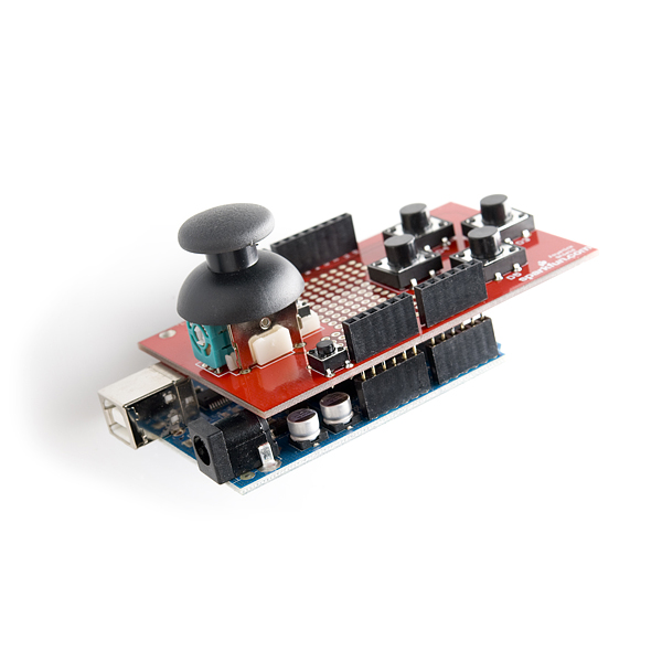
Once you've completed your shield it should look like this when connected on top of your Arduino:

alt text

alt text
Now it's time to make your joystick shield control something!

Arduino Examples: Shield

The joystick shield provides simple analog inputs along with four separate buttons and one button under the joystick itself. The joystick can be used for controlling outputs such as a melody or pixels on a screen. The buttons can be used for navigation or game control. If you want to jump directly into the example sketches, download and unzip the examples from the GitHub repo to dive in.

  • JoystickArduinoBasicExample.ino - Printing joystick values and button presses to the console.
  • JoystickArduinoIntermediateExample.ino - This code does the same thing as the basic code but includes more positions on the joystick.
  • JoystickArduinoMelodyControl.ino - Controlling a melody and tempo with the joystick and a piezo buzzer.
  • SparkFunJoystickShieldSampleSketch.ino - Example from the demo video to use with the a serial enabled LCD.

For the scope of this tutorial, we will focus on the first two examples to read the joystick and buttons using the shield. If you have the joystick breakout, you can still follow along as long as everything is wired like the shield and use the pins definitions in the code for reference. Also, you can check out the additional examples if you have additional hardware like a piezo buzzer or serial enabled LCD.

Basic Example

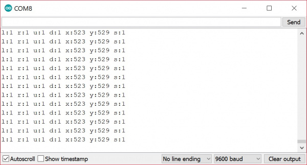
After downloading the examples, open the JoystickArduinoBasicExample.ino sketch, select Arduino/Genuino Uno as the board and the COM port that the board enumerated on, and hit the upload button. Open the serial monitor at 9600 baud and test out the joystick shield to observe the joystick and button behaviors.

Thumb Joystick Shield Raw Output

If you've been following along with the tutorial, the output looks similar to the output from the breakout board example.There are two differences between the breakout and shield. One apparent difference is the output. There are more values for each line due to additional four buttons. If no button is pressed, they will read as a 1. If a button is pressed, they will read as 0.

The second difference is more subtle. The orientation of the joystick is rotated 90°. The "vertical" position is referenced with as the "x-axis" while the "horizontal" is referenced as the "y-axis". The output indicates that the joystick is not moving when the values are around 520. Moving the joystick up toward the "AREF" pin, the joystick will read the same value for the x-axis while y-axis component will jump to 1023. Moving it clockwise to the right, the x-axis will read a value of about 0 while the y-axis component will sit at the resting value of about 520 again. As the joystick moves down toward you, you'll notice the x-axis will sit at it's resting value again while the y-axis component will drop to 0. Moving the joystick to the left, you'll notice the x-axis component jump up to 1023 while the y-axis component sit back to its resting value. Finally, the select button will read as 0 when pressing down on the joystick.

Intermediate Example

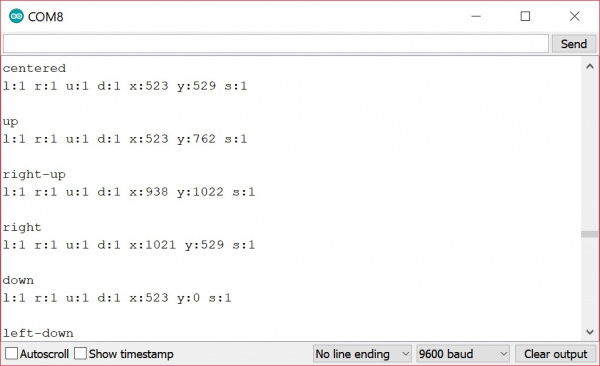
Open the JoystickArduinoIntermediateExample.ino sketch, select Arduino/Genuino Uno as the board and the COM port that the board enumerated on, and hit the upload button. Open the serial monitor at 9600 baud and test out the joystick shield to observe the joystick and button behaviors.

Thumb Joystick Shield Raw

Again, you'll notice that the raw output is the same as the basic example. However, there is an additional line indicating the position of the joystick. The code is a little bit more complicated with the nested if statements to check the joystick's position. The code breaks the position up into 9 positions:

  • center
  • up
  • right-up
  • right
  • right-down
  • down
  • left-down
  • left
  • left-up

Code To Note

Once you've got the shield assembled, you can begin to change the example code to make the joystick do your bidding. Here are a few in-depth explanations about the code.

How Do I Find the Current Position of the Joystick?

The position of the joystick is calculated from the two potentiometers in the joystick. The joystick can move in two dimensions which typically would represent X and Y coordinates but could represent any two dimensional quantity. To read the potentiometers we use the analogRead() function which returns a number from 0 to 1023. We need to supply an analog pin number to the function — for the joystick shield the X position is read from analog pin 0 and the Y position is read from analog pin 1:

language:c
Serial.println(analogRead(0)); // Prints current X position
Serial.println(analogRead(1)); // Prints current Y position

It is a good technique — because it clarifies your intent — to use ''constants'' for values that will not change when your sketch runs. With this in mind, the following sketch snippet sets up constants for the analog pins used and prints the current X and Y positions to the serial console:

language:c
const byte PIN_ANALOG_X = 0;
const byte PIN_ANALOG_Y = 1;

void setup() {
  Serial.begin(9600);
}

void loop() {

  Serial.print("x:");
  Serial.print(analogRead(PIN_ANALOG_X));
  Serial.print("");

  Serial.print("y:");
  Serial.print(analogRead(PIN_ANALOG_Y));
  Serial.print("");

  Serial.println();
}

How Do I Find the Current Direction of the Joystick?

It can be useful to use the value of the X and Y position to determine if the joystick is centered or moved in one of 8 directions (i.e. up, right-up, right, right-down, down, left-down, left, left-up).

Since we know the value in each dimension will be between 0 and 1023 you might expect the centre value to be around 511 or 512 but because the joysticks are physical devices the actual value is unlikely to be that exact. If we choose the wrong value we'll find that our joystick will be detected as moving in a particular direction even though it is centered.

To work around this issue we specify two "threshold" values and consider that any value within that range should be considered "centered":

language:bash
|----------|----|----------|
0         505  515        1023

The threshold values you choose may be different depending on your joystick. We specify the values as constants in the code:

language:c
const int X_THRESHOLD_LOW = 505;
const int X_THRESHOLD_HIGH = 515;    

const int Y_THRESHOLD_LOW = 500;
const int Y_THRESHOLD_HIGH = 510;

Next, we want to map our value in each dimension from a position range of 0 to 1023 to a direction value in the range -1 to 1. For the X, dimension -1 means moved to the left, 0 means not moved in the X dimension and 1 means moved to the right. For the Y dimension -1 means moved down, 0 means not moved in the Y dimension and 1 means moved up.

We start by setting the direction in each dimension to 0 ("centered") and then we use if/else statements to check if the position value in either dimension is above or below our threshold values:

language:c
x_direction = 0;
y_direction = 0;

x_position = analogRead(PIN_ANALOG_X);
y_position = analogRead(PIN_ANALOG_Y);

if (x_position > X_THRESHOLD_HIGH) {
  x_direction = 1;
} else if (x_position < X_THRESHOLD_LOW) {
  x_direction = -1;
}

if (y_position > Y_THRESHOLD_HIGH) {
  y_direction = 1;
} else if (y_position < Y_THRESHOLD_LOW) {
  y_direction = -1;
}

The Arduino provides a map() function which in theory we could use instead of if/else but the method is complicated by the centering issues so we won't consider that approach here.

As you can see in the next complete example we then use if/else statements to print the direction — you can modify this example to perform whatever action you need:

language:c
const byte PIN_ANALOG_X = 0;
const byte PIN_ANALOG_Y = 1;

const int X_THRESHOLD_LOW = 505;
const int X_THRESHOLD_HIGH = 515;

const int Y_THRESHOLD_LOW = 500;
const int Y_THRESHOLD_HIGH = 510;

int x_position;
int y_position;

int x_direction;
int y_direction;

void setup() {
  Serial.begin(9600);
}

void loop () {
  x_direction = 0;
  y_direction = 0;

  x_position = analogRead(PIN_ANALOG_X);
  y_position = analogRead(PIN_ANALOG_Y);

  if (x_position > X_THRESHOLD_HIGH) {
    x_direction = 1;
  } else if (x_position < X_THRESHOLD_LOW) {
    x_direction = -1;
  }

  if (y_position > Y_THRESHOLD_HIGH) {
    y_direction = 1;
  } else if (y_position < Y_THRESHOLD_LOW) {
    y_direction = -1;
  }


  if (x_direction == -1) {
    if (y_direction == -1) {
      Serial.println("left-down");
    } else if (y_direction == 0) {
      Serial.println("left");
    } else {
      // y_direction == 1
      Serial.println("left-up");
    }
  } else if (x_direction == 0) {
    if (y_direction == -1) {
      Serial.println("down");
    } else if (y_direction == 0) {
      Serial.println("centered");
    } else {
      // y_direction == 1
      Serial.println("up");
    }
  } else {
    // x_direction == 1
    if (y_direction == -1) {
      Serial.println("right-down");
    } else if (y_direction == 0) {
      Serial.println("right");
    } else {
      // y_direction == 1
      Serial.println("right-up");
    }
  }
}

How Do I Set Up the Arduino So I Can Know When a Button has Been Pushed on the Joystick Shield?

Before you can know if a button on the shield has been pushed, you need to set up your Arduino to recognize the buttons. Unsurprisingly, you will perform this setup in the... setup() function!

First, we define constants for the Arduino pin associated with each button:

language:c
// Select button is triggered when joystick is pressed
const byte PIN_BUTTON_SELECT = 2;

const byte PIN_BUTTON_RIGHT = 3;
const byte PIN_BUTTON_UP = 4;
const byte PIN_BUTTON_DOWN = 5;
const byte PIN_BUTTON_LEFT = 6;

If you've used a pushbutton switch before you may have noticed a resistor is normally required in order to detect a known voltage when the button is not pressed. To reduce the number of parts required this shield has been designed not to require resistors on the shield itself. Are you thinking to yourself "if push buttons require resistors and the shield has no resistors how can we get the shield to work?"? If you're not thinking that then you can probably skip reading this bit. (And if you're thinking "I'm really hungry" it might be time to put down the electronics and get some food.)

It turns out your Arduino actually has internal resistors connected to the pins inside the microcontroller. In order to use the internal resistors we need to "enable the internal pull-up resistors". If that sounds to you like "hoist the jib and unfurl the main stay" then I can explain some more:

When a "pull-up" resistor is connected to a push button it means that the voltage level when the button is not pressed will be HIGH because the resistors "pulls the voltage level up" to HIGH when the button is not pressed. On a typical Arduino a pin that is HIGH will be at 5 volts. When the push button is pressed the pin will read as LOW because there is less resistance between the pin and ground than there is between the pin and 5 volts.

To enable a pin's pull-up resistor you first set the pin as an input and then enable the pull-up:

language:c
pinMode(PIN_BUTTON_RIGHT, INPUT);
digitalWrite(PIN_BUTTON_RIGHT, HIGH);

The actual code to enable the pull-up doesn't really make any sense if you read it literally but that's the way it works.

Other than remembering that an unpressed button will read as HIGH with a pull-up resistor and a pressed button will read as LOW you don't need to remember or understand the other details.

In order to configure each pin to be an input and enable the pull up resistors we use the following code:

language:c
void setup() {

  pinMode(PIN_BUTTON_RIGHT, INPUT);  
  digitalWrite(PIN_BUTTON_RIGHT, HIGH);

  pinMode(PIN_BUTTON_LEFT, INPUT);  
  digitalWrite(PIN_BUTTON_LEFT, HIGH);

  pinMode(PIN_BUTTON_UP, INPUT);  
  digitalWrite(PIN_BUTTON_UP, HIGH);

  pinMode(PIN_BUTTON_DOWN, INPUT);  
  digitalWrite(PIN_BUTTON_DOWN, HIGH);

  pinMode(PIN_BUTTON_SELECT, INPUT);  
  digitalWrite(PIN_BUTTON_SELECT, HIGH);
}

See the next section to learn how to read whether a button is pressed or not.

How Do I Know When a Button On the Joystick Shield has Been Pressed?

Once you have set up your Arduino to recognize the buttons (see above) you can tell whether the button is pressed with the digitalRead() function. When the value read is LOW the button is pressed and when the value is HIGH the button is not pressed.

language:c
if (digitalRead(PIN_BUTTON_LEFT) == LOW) {
    // Button is pressed
} else {
   // Button is not pressed
}

The following complete example will print the state of each button and the value of the joystick to the Arduino serial console:

language:c
// Store the Arduino pin associated with each input

// Select button is triggered when joystick is pressed
const byte PIN_BUTTON_SELECT = 2; 

const byte PIN_BUTTON_RIGHT = 3;
const byte PIN_BUTTON_UP = 4;
const byte PIN_BUTTON_DOWN = 5;
const byte PIN_BUTTON_LEFT = 6;

const byte PIN_ANALOG_X = 0;
const byte PIN_ANALOG_Y = 1;

void setup() {
  Serial.begin(9600);

  pinMode(PIN_BUTTON_RIGHT, INPUT);  
  digitalWrite(PIN_BUTTON_RIGHT, HIGH);

  pinMode(PIN_BUTTON_LEFT, INPUT);  
  digitalWrite(PIN_BUTTON_LEFT, HIGH);

  pinMode(PIN_BUTTON_UP, INPUT);  
  digitalWrite(PIN_BUTTON_UP, HIGH);

  pinMode(PIN_BUTTON_DOWN, INPUT);  
  digitalWrite(PIN_BUTTON_DOWN, HIGH);

  pinMode(PIN_BUTTON_SELECT, INPUT);  
  digitalWrite(PIN_BUTTON_SELECT, HIGH);  
}

void loop() {
  Serial.print("l:");
  Serial.print(digitalRead(PIN_BUTTON_LEFT));
  Serial.print("");

  Serial.print("r:");
  Serial.print(digitalRead(PIN_BUTTON_RIGHT));
  Serial.print("");

  Serial.print("u:");
  Serial.print(digitalRead(PIN_BUTTON_UP));
  Serial.print("");

  Serial.print("d:");
  Serial.print(digitalRead(PIN_BUTTON_DOWN));
  Serial.print("");

  Serial.print("x:");
  Serial.print(analogRead(PIN_ANALOG_X));
  Serial.print("");

  Serial.print("y:");
  Serial.print(analogRead(PIN_ANALOG_Y));
  Serial.print("");  

  Serial.print("s:");
  Serial.print(digitalRead(PIN_BUTTON_SELECT));
  Serial.print("");

  Serial.println();
}

Resources and Going Further

Now that you've successfully got your joystick up and running, it's time to incorporate it into your own project!

For more information, check out the resources below:

Need some inspiration for your next project? Check out some of these related tutorials:

BadgerHack: Gaming Add-On Kit

Make a Breakout clone with the BadgerHack Gaming Add-On Kit.

Wireless Joystick Hookup Guide

A hookup guide for the SparkFun Wireless Joystick Kit.

Serial Controlled Motor Driver Hookup Guide

Hookup guide for the Serial Controlled Motor Driver

If you have no idea what to do with a joystick, checkout the following videos:


learn.sparkfun.com | CC BY-SA 3.0 | SparkFun Electronics | Niwot, Colorado


Qwiic Joystick Hookup Guide

$
0
0

Qwiic Joystick Hookup Guide a learn.sparkfun.com tutorial

Available online at: http://sfe.io/t847

Introduction

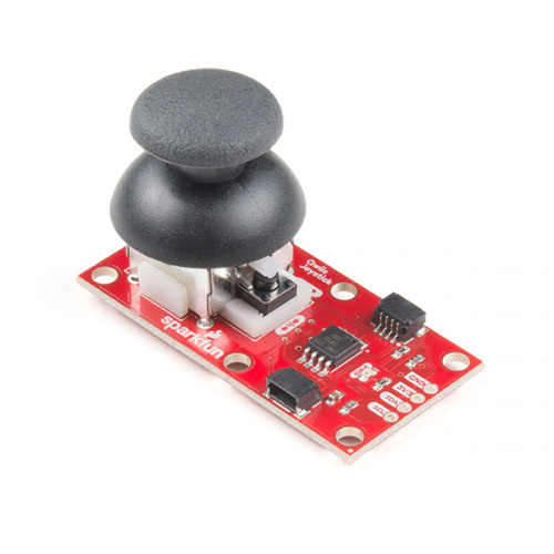
Now, you can easily add an HID/controller to your project! The SparkFun Qwiic Joystick combines the convenience of the Qwiic connection system and an analog joystick that feels reminiscent of the thumbstick from a PlayStation 2 controller.

SparkFun Qwiic Joystick

SparkFun Qwiic Joystick

COM-15168
$9.95

Thanks to an ATtiny85 on the Qwiic Joystick, all the necessary bits are taken care of and your microcontroller only needs to look for your inputs in the registers of the I2C device.

Required Materials

The Qwiic Joystick does need a few additional items for you to get started. The RedBoard Qwiic is for the Arduino examples and the Qwiic Hat is for the Raspberry Pi example (see note below). You may already have a few of these items, so feel free to modify your cart based on your needs.

SparkFun RedBoard Qwiic

SparkFun RedBoard Qwiic

DEV-15123
$19.95
SparkFun Qwiic Cable Kit

SparkFun Qwiic Cable Kit

KIT-15081
$7.95
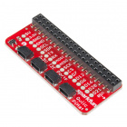
SparkFun Qwiic HAT for Raspberry Pi

SparkFun Qwiic HAT for Raspberry Pi

DEV-14459
$5.95
1
Raspberry Pi Example: If you don't already have them, you will need a Raspberry Pi and standard peripherals. An example setup is listed below.
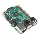
Raspberry Pi 3

Raspberry Pi 3

DEV-13825
$39.95
92
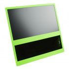
pi-topCEED (Green)

pi-topCEED (Green)

KIT-14035
$114.95
4
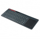
Multimedia Wireless Keyboard

Multimedia Wireless Keyboard

WIG-14271
$29.95
2
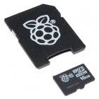
Raspberry Pi™ - 16GB MicroSD NOOBS Card

Raspberry Pi™ - 16GB MicroSD NOOBS Card

COM-13945
3

Suggested Reading

If you're unfamiliar with jumper pads, I2C, or Python be sure to checkout some of these foundational tutorials.

Logic Levels

Learn the difference between 3.3V and 5V devices and logic levels.

I2C

An introduction to I2C, one of the main embedded communications protocols in use today.

How to Work with Jumper Pads and PCB Traces

Handling PCB jumper pads and traces is an essential skill. Learn how to cut a PCB trace, add a solder jumper between pads to reroute connections, and repair a trace with the green wire method if a trace is damaged.

RedBoard Qwiic Hookup Guide

This tutorial covers the basic functionality of the RedBoard Qwiic. This tutorial also covers how to get started blinking an LED and using the Qwiic system.

Raspberry Pi SPI and I2C Tutorial

Learn how to use serial I2C and SPI buses on your Raspberry Pi using the wiringPi I/O library for C/C++ and spidev/smbus for Python.

Qwiic HAT for Raspberry Pi Hookup Guide

Get started interfacing your Qwiic enabled boards with your Raspberry Pi. This Qwiic connects the I2C bus (GND, 3.3V, SDA, and SCL) on your Raspberry Pi to an array of Qwiic connectors.

Python Programming Tutorial: Getting Started with the Raspberry Pi

This guide will show you how to write programs on your Raspberry Pi using Python to control hardware.

If you aren't familiar with the Qwiic system, we recommend reading here for an overview.

Qwiic Connect System

Hardware Overview

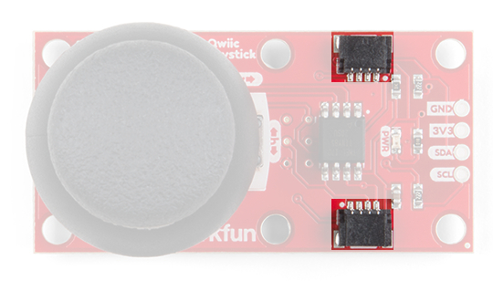
The Qwiic Joystick will report the thumbstick position over I2C and is designed to be compatible with the Qwiic system so you can add it to your project solder-free!

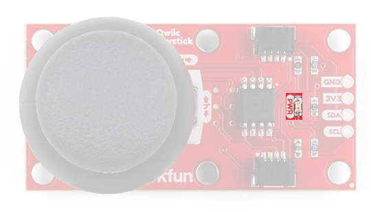
Power LED

There is a power status LED to help make sure that your Qwiic Joystick is getting power. You can power the board either through the polarizedQwiic connector system or the breakout pins (PWR and GND) provided. The Qwiic system is meant to run on 3.3V, be sure that you are NOT using another voltage when using the Qwiic system.

alt text

Joystick

The joystick is similar to the analog joysticks on PS2 (PlayStation 2) controllers. Directional movements are simply measured with two 10 kΩ potentiometers, one for each axis. This joystick also has a select button that is actuated when the joystick is pressed down.

Thumb Joystick

Thumb Joystick

COM-09032
$3.95
5

The two potentiometers are connected to the analog to digital converter (ADC) of the ATtiny85. The select button operates as a digital input on the ATtiny85. This allows the firmware to read the knob position and any button presses.

Troubleshooting Tip: Due to resistor manufacturing tolerances, the joystick may not read exactly half of VCC when at rest. You may want to make a note of the "zero" reading, and store that value into your program if necessary.

Joystick Orientation

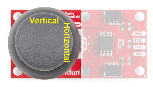
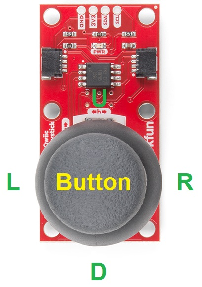
The joystick contains two potentiometers, connected with a gimbal mechanism that separates the horizontal and vertical movements (orientation shown below).

alt text

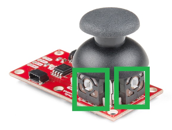
The potentiometers are the two blue or black boxes on the sides of the joystick. If you move the joystick while watching the center shaft of each potentiometer, you'll see that each of the potentiometers will pick up movement on only one axis. Clever, isn't it?

alt text

Select Button

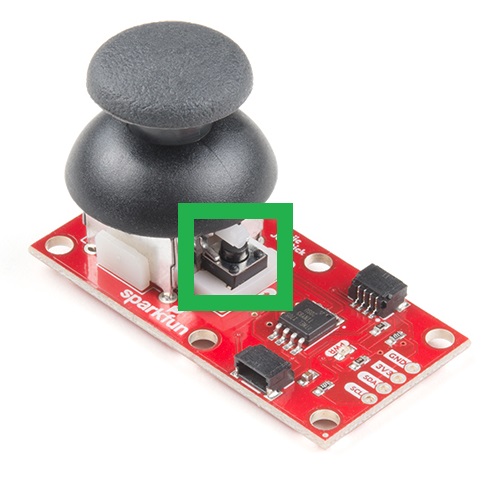
The joystick also contains a momentary button which activates when you push down on the cap. The button is the small black box on the side of the joystick. If you push down on the cap, you can see a lever pushing down on the head of the button. The lever works no matter what position the joystick is in. That is pretty cool!

alt text

ATtiny85

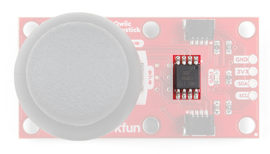
With the pre-installed firmware, the ATtiny85 is acts as an intermediary (microcontroller) for the analog and digital inputs from the joystick. This allows the Qwiic Joystick to report its position over I2C.

alt text
Note: To flash your own firmware, at minimum, you will need an programmer for the ATtiny and a pogo pin adapter. Writing and uploading firmware is not easily done, unless you know what you are doing; this is inadvisable for beginners.

Qwiic & I2C

I2C Address

In the firmware, the Qwiic Joystick’s I2C address is configurable so you can add a bunch of them to the same bus without collision issues.

Factory Default I2C Slave Address: 0x20

I2C Registers

AddressDescription
0x00Default I2C Slave Address from EEPROM
0x01 - 0x02Firmware Version (MSB First)
0x03 - 0x04Current Horizontal Position (MSB First)
0x05 - 0x06Current Vertical Position (MSB First)
0x07Current Button Position
0x08Button Status: Indicates if button was pressed since last read of button state. Clears after read.
0x09Configuration or "Locking" Register - Prevents random I2C address changes during I2C scans and register dumps. Must be set to 0x13 before an address change gets saved to the EEPROM.
0x0ACurrent/Set I2C Slave Address (Write). Stored in EEPROM.


Note: In the registers for the joystick position, the MSB contains the first 8 bits of the 10-bit ADC value and the LSB contains the last two bits. As an example, this is how the library converts the two registers back to a 10-bit value.

uint_16t full10bitvalue = ((MSB << 8) | LSB) >> 6;

You could potentially only look at the MSB and get an 8-bit reading (for 256 positions). The firmware was intentionally written this way in the hopes that it would be useful for customers who didn't need the full resolution of the joystick position.
Troubleshooting Tip:
Please be aware, the first time the joystick position registers are read, it will have a maximum value (all 1's in binary). I am not sure if it is something in the firmware or if has something to do with the ATtiny85, but the initial read will be 1023. Once that is read, everything reading after should be accurate (excluding the manufacturing tolerances mentioned above). If you have a fix for this issue, please feel free to comment on this tutorial or create a pull request on the GitHub repository.

Connections

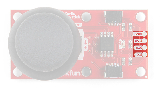
The board provides four labeled breakout pins. You can connect these lines to the I2C bus of your microcontroller and power pins (3.3V and GND), if it doesn't have a Qwiic connector.

alt text

However, the simplest way to use the Qwiic Joystick is through the Qwiic connect system. The connectors are polarized for the I2C connection and power. (*They are tied to the breakout pins.)

alt text
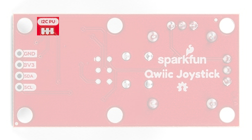
I2C Pull-up Jumpers

Cutting the I2C jumper will remove the 2.2k Ohm resistors from the I2C bus. If you have many devices on your I2C bus you may want to remove these jumpers. Not sure how to cut a jumper? Read here!

alt text

Hardware Assembly

Arduino Examples

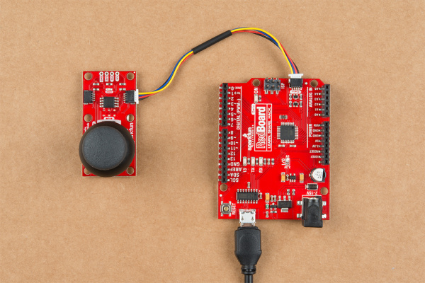
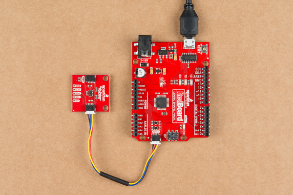
With the Qwiic connector system, assembling the hardware is simple. All you need to do is connect your Qwiic Joystick to the RedBoard Qwiic with a Qwiic cable. Otherwise, you can use the I2C pins of your microcontroller; just be aware of logic levels, that the operating voltage of the ATtiny85 ranges from 1.8 to 5.5V, and the EEPROM needs at least 2V or it will get corrupted .

alt text

Note: This tutorial assumes you are familiar with Arduino products and you are using the latest stable version of the Arduino IDE on your desktop. If this is your first time using the Arduino IDE, please review our tutorial on installing the Arduino IDE.

Troubleshooting Tip:
It is best to power the board at the recommended 3.3V of the Qwiic system. However, if you do happen to accidentally corrupt the EEPROM and inject a new, random I2C address. There is a way to replace the I2C address and store it in the EEPROM again. Follow the following steps exactly, you will need to use the Arduino Library from below:

  1. Connect the Qwiic Joystick to a RedBoard Qwiic with a Qwiic cable.
  2. Run Example 3 to find the current I2C address.
  3. Modify Example 2 to use the I2C address you just found.
  4. Run Example 2 and change the I2C address back to the default address.
  5. Unplug and the Qwiic Joystick and plug it back in. The EEPROM should be reset to the default I2C address and be ready to use again.

Raspberry Pi Example

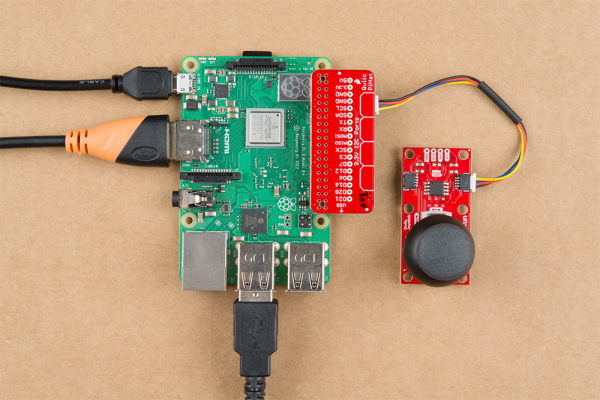
With the Qwiic connector system, assembling the hardware is simple. You will need a Qwiic cable, a SparkFun Qwiic HAT for Raspberry Pi, and a Raspberry Pi setup with the Raspbian OS, monitor, and standard peripherals. (*If you are unfamiliar with the Qwiic Hat, you can find the Hookup Guide here.)

alt text

Note: This tutorial assumes you are familiar with using a Raspberry Pi and you have the latest (full... with recommended software) version of Raspbian OS your Raspberry Pi. You can download the latest version of the Raspbian OS from the Raspberry Pi Foundation website. As of Feb. 13th 2019, we recommend the Raspbian Stretch with desktop and recommended software option.

If this is your first time using a Raspberry Pi, please head over to the Raspberry Pi Foundation website to use their quickstart guides. We have listed a few of them here:

  1. Setting up your Raspberry Pi
  2. Using your Raspberry Pi
  3. Documentation:
  4. Setup Documentation
    Installation Documentation
    Raspbian Documentation
    SD card Documentation

Arduino Library

The easiest way to install the Arduino library is by searching SparkFun Qwiic Joystick inside the Arduino library manager. To manually install, head on over to the GitHub Page or feel free to download the library here!

Library Functions

The Arduino library is commented and the functions should be self-explanatory. However, below is a detailed list of the available library functions.

.begin() or .begin(Wire, deviceAddress)
Creates a connection to an I2C device over the I2C bus using the default or specified I2C address.

Input: uint8_t deviceAddress
Unasssigned 8-bit integer for device address. If not defined, the library will use the default I2C address stored in the I2C library (0x20).
Output: Boolean

True- Connected to I2C device.
False- No device found or connected.

isConnected()
Tries to connect to the device at the I2C address stored in the library.

Output: Boolean

True- Connected to I2C device.
False- No device found or connected.

setI2CAddress(newAddress)
Changes the I2C address to newAddress. Once changed, the new I2C address is saved in the EEPROM of the Qwiic Joystick. Reconnects to device using new I2C address. (The new address is printed out in the Serial Monitor.)

Input: uint8_t newAddress

Unasssigned 8-bit integer for device address.

getHorizontal()
Returns the ADC value of the joystick horizontal position.

Output: uint16_t

Unasssigned 10-bit integer [0 - 1023] for ADC value of the joystick position in the horizontal axis.

getVertical()
Returns the ADC value of the joystick vertical position.

Output: uint16_t

Unasssigned 10-bit integer [0 - 1023] for ADC value of the joystick position in the vertical axis.

getButton()
Returns the current button state (clears check button indicator - see below).

Output: byte

0 - Button is currently being pressed.
1 - Button is currently unpressed.

checkButton()
Indicates if the button was pressed between reads of the button state or calls of this function. The register for this indicator is then cleared.

Output: byte

0 - Button is was NOT pressed.
1 - Button is was pressed.

getVersion()
Returns a string of the firmware version number.

Output: String AAA.BBB

AAA - Firmware Version (Major)
BBB - Firmware Version (Minor)

Examples

There are four examples in the Qwiic Joystick Arduino Library to get you started with using Qwiic Joystick. These example files are named with self-explanatory titles, but in case you want more information, see the descriptions below.

  • Example1_Basic_Readings

    This example connects to the Qwiic Joystick using the default I2C address saved in the library. The sketch looks at the registers for the current joystick position and button state. The example then prints out those values over the Serial Monitor.

  • Example2_I2C_Address_and_Firmware

    This example connects to the Qwiic Joystick using the default I2C address set in the sketch and then prints out the I2C address and firmware version over the Serial Monitor. The sketch then, takes an input from the Serial Monitor to change the I2C address using a decimal value (DEC). Once the I2C address is changed, it is stored in the EEPROM of the Qwiic Joystick. After, the sketch connects to the joystick using the new I2C address and reads the registers for the firmware version again. The example then prints out those values over the Serial Monitor again.

  • Example3_I2C_Scanner

    This example is from the I2C scanner example from the Arduino Playground webpage. The sketch scans for devices on the I2C bus and reports them on the Serial Monitor. This is useful for users who have forgotten the changed I2C address of their boards.

  • Example4_Joystic_Serial_Output

    This example shows a basic example of how to begin to use the Qwiic Joystick as an HID. The example sketch takes values of the joystick and converts it to directional printouts on the Serial Monitor.

Arduino Examples

Note: This section is an example of using the Qwiic Joystick and the RedBoard Qwiic with the Arduino IDE. It is not intended to be a guide for using I2C devices with the Arduino IDE.

Please use the following links and the internet for a better understanding of I2C and how it works in the Arduino IDE:

Example 1: Basic Readings

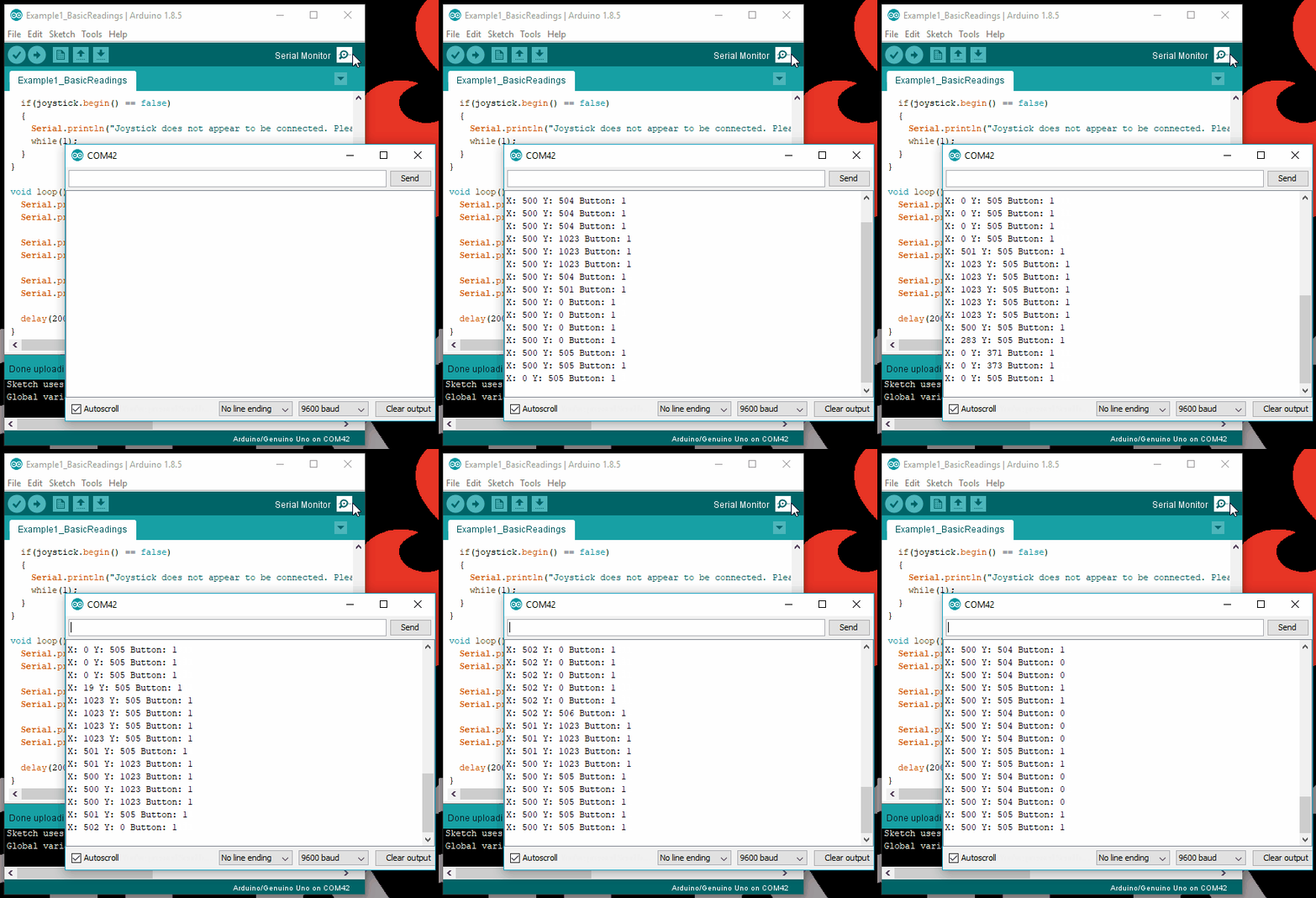
This sketch looks at the registers for the current joystick position and button state; the values are sent to the Serial Monitor. Make sure you are using a baudrate of 9600bps.

alt text

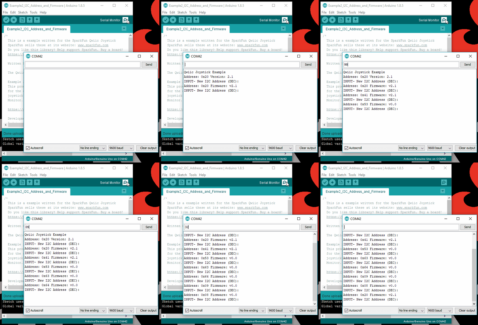
Example 2: I2C Address Change and Firmware Version Read

This sketch takes an entry from the Serial Monitor, in a decimal value, and changes the I2C address of the device. The firmware version is then read to confirm that the address was changed. Make sure you are using a baudrate of 9600bps.

alt text

Example 3: I2C Scanner

This sketch is from the I2C scanner example from the Arduino Playground webpage. The sketch scans for devices on the I2C bus and reports them on the Serial Monitor. Make sure you are using a baudrate of 9600bps.

Example 4: Joystick Serial Output

This sketch takes values of the joystick and converts it to directional printouts on the Serial Monitor. Make sure you are using a baudrate of 9600bps.

alt text

Python Examples

Note: This section is an example of using the Qwiic Joystick with the Raspberry Pi in Python. It is not intended to be a guide for using I2C devices with a Raspberry Pi or a tutorial on Python.

Please use the following links and the internet for a better understanding of I2C and how it works in the Arduino IDE:

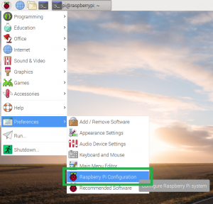
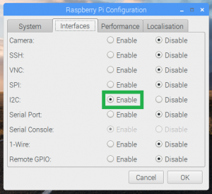
Enable I2C Interface

If it isn't already enabled, enable I2C interface in Preferences > Raspberry Pi Configuration panel.

alt textalt text

Check for Device Using Command Line

On the (full) Raspbian OS, i2ctools should be pre-installed (if it is not, follow the instructions here). With the Qwiic Joystick and Qwiick Hat attached to the Raspberry Pi, run the following command in the terminal/commandline.

i2cdetect -y 1

Download and Run Python Examples

Download the Python Examples from the GitHub repository. All you need to do is open an example python file and execute the module. You can do this in Python 3 or another compatible, programming text editor like Geany.

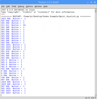
Basic Readings

Below is a screenshot python shell from the Basic Readings example file.

alt text

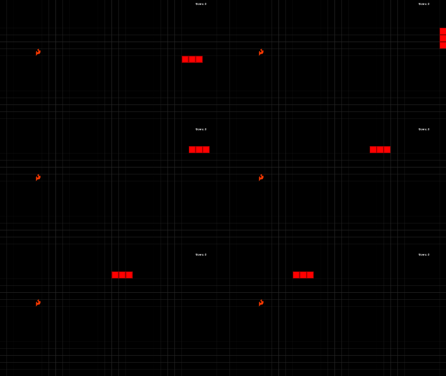
Snake Game

When you run the Snake Game example code, you only need to click the button to start the game. (*Shout out to Al Sweigart for his Wormy example, which was adapted to work with the Qwiic Joystick.)

alt text
Troubleshooting Tips: I did run into an error with the python example codes. Unfortunately, I am not an expert in Python and the Raspberry Pi. However, I got around this by having the error print out instead of terminating the script. From what I could deduce based on the available information on the internet, the error [Errno 121] Remote I/O error is an issue with the I2C bus and how SMBUS interacts with the slave device.

You will also get an [Errno 121] Remote I/O error if your I2C address is defined wrong.

Resources and Going Further

For more information, check out the resources below:

Product Information

Example Code and Arduino Library

Need help getting started with Arduino and I2C? Check out these resources here:

Need help getting started with your Raspberry Pi? Check out these resources here:

Need help getting started with Python and I2C? Check out these resources here:

Need some inspiration for your next project? Check out some of these other Qwiic product tutorials:

Qwiic Micro OLED Hookup Guide

Get started displaying things with the Qwiic Micro OLED.

RedBoard Edge Hookup Guide

The RedBoard Edge is a RedBoard that's been rebuilt around the idea that projects are eventually put into an enclosure to help clean up their look.

GPS-RTK Hookup Guide

Find out where you are! Use this easy hook-up guide to get up and running with the SparkFun high precision GPS-RTK board.

SparkFun Pro nRF52840 Mini Hookup Guide

A hardware overview and hookup guide for the SparkFun Pro nRF52840 Mini -- a breakout for Nordic's impossibly cool Bluetooth/ARM Cortex M4 SoC.

learn.sparkfun.com | CC BY-SA 3.0 | SparkFun Electronics | Niwot, Colorado
Qwiic Transparent OLED HUD Hookup Guide

$
0
0

Qwiic Transparent OLED HUD Hookup Guide a learn.sparkfun.com tutorial

Available online at: http://sfe.io/t843

Introduction

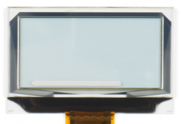
Clear screens are no longer a thing of the Sci-Fi world! The Qwiic Transparent OLED HUD (Head Up Display) is SparkFun's answer to all of your futuristic transparent HUD needs. While you can see through the display, each segment is area colored, meaning that while no one segment can change colors, there are different colored segments on the display.

SparkFun Transparent OLED HUD Breakout (Qwiic)

SparkFun Transparent OLED HUD Breakout (Qwiic)

LCD-15079
$99.95

Required Materials

To follow along with this tutorial, you will need the following materials. You may not need everything though depending on what you have. Add it to your cart, read through the guide, and adjust the cart as necessary.

Microcontroller

The Transparent OLED HUD requires quite a bit of RAM, so you'll need a microcontroller with at least 5500 bytes of RAM to control everything. Check out the below for some possible options.

SparkFun ESP32 Thing

SparkFun ESP32 Thing

DEV-13907
$21.95
60
Arduino Mega 2560 R3

Arduino Mega 2560 R3

DEV-11061
$38.95
53
Teensy 3.6

Teensy 3.6

DEV-14057
$29.25
13
SparkFun ESP8266 Thing - Dev Board

SparkFun ESP8266 Thing - Dev Board

WRL-13711
$16.95
69

Cable

Now to get into the Qwiic ecosystem, the key will be using a Qwiic shields to match your preference of microcontroller. In this tutorial, we'll be using Qwiic-to-breadboard adapter cable. You will also need a cable to upload code to your microcontroller.

USB Cable A to B - 6 Foot

USB Cable A to B - 6 Foot

CAB-00512
$3.95
1
Qwiic Cable - Breadboard Jumper (4-pin)

Qwiic Cable - Breadboard Jumper (4-pin)

PRT-14425
$1.50

Suggested Reading

If you aren't familiar with the Qwiic system, we recommend reading here for an overview.

Qwiic Connect System

We would also recommend taking a look at the following tutorials if you aren't familiar with them.

Serial Communication

Asynchronous serial communication concepts: packets, signal levels, baud rates, UARTs and more!

I2C

An introduction to I2C, one of the main embedded communications protocols in use today.

Serial Terminal Basics

This tutorial will show you how to communicate with your serial devices using a variety of terminal emulator applications.

Hardware Overview

First let's check out some of the characteristics of the Qwiic HUD we're dealing with, so we know what to expect out of the board.

CharacteristicRange
Operating Voltage1.65V-3.3V
Supply Current400 mA
I2C Addresses0x30, 0x31

Notice that the OLED can pull about 400 mA of current, so ensure you have a robust enough power supply, especially if the OLED isn't the only thing you're powering. Also notice that the OLED sits on two I2C addresses, so make sure that any other I2C devices don't take up addresses 0x30 and 0x31.

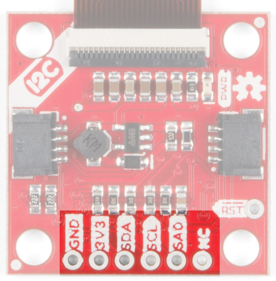
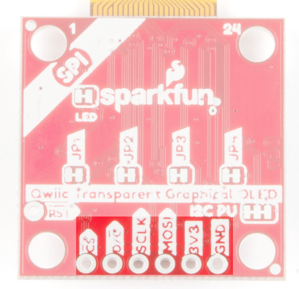
Pins

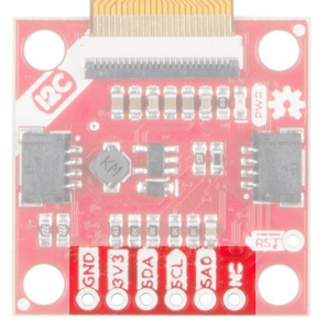
The following table lists all of the transparent OLED's pins and their functionality.

PinDescriptionDirection
GNDGroundIn
3.3VPowerIn
SDADataBi-directional
SCLClockIn

Optional Features

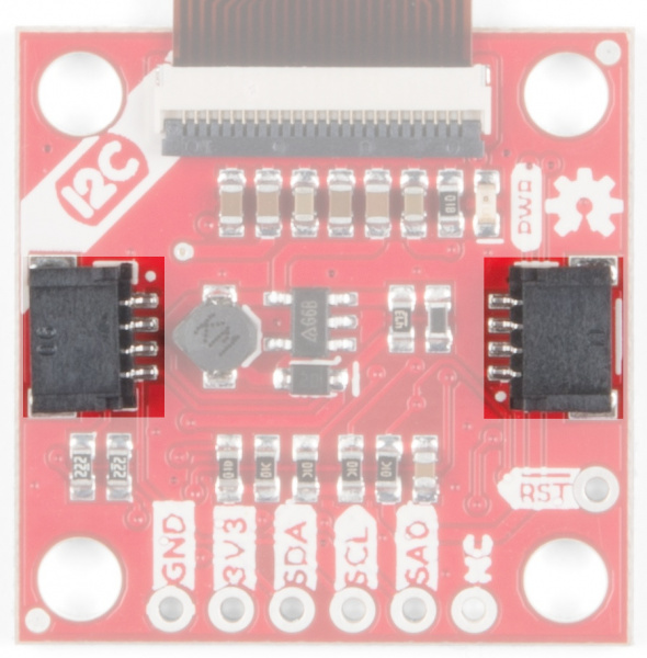
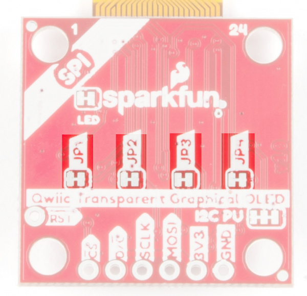
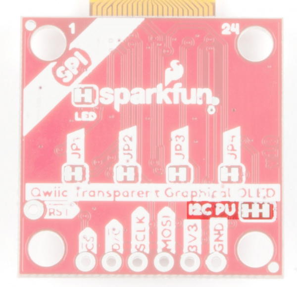
The Transparent OLED breakout has pull-up resistors attached to the I2C bus; if multiple sensors are connected to the bus with the pull-up resistors enabled, the parallel equivalent resistance will create too strong of a pull-up for the bus to operate correctly. As a general rule of thumb, disable all but one pair of pull-up resistors if multiple devices are connected to the bus. If you need to disconnect the pull-up resistors they can be removed by cutting the traces on the corresponding jumpers highlighted below.

Pull-up Jumpers

Pull-up Jumpers

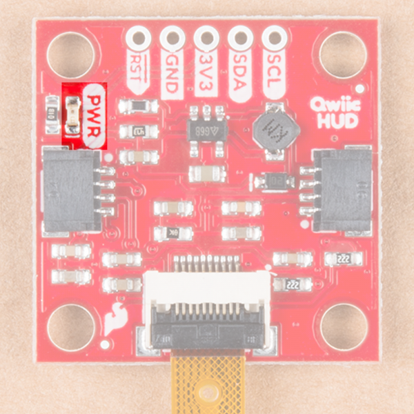
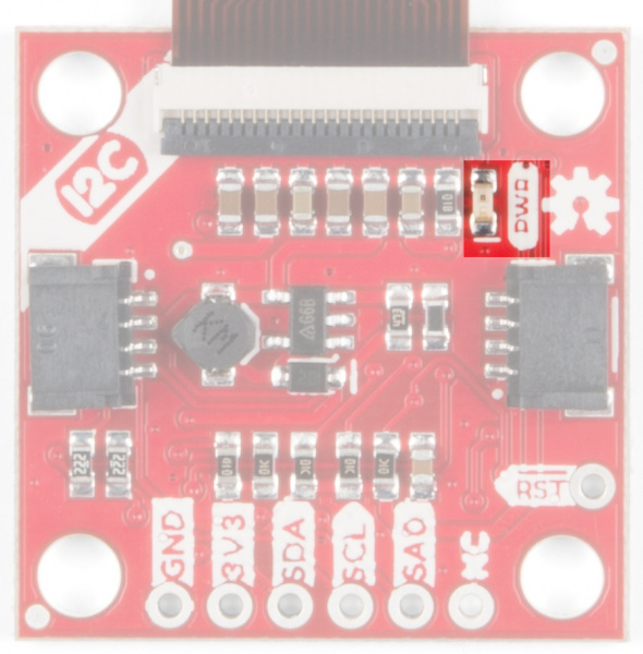
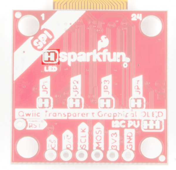
The onboard LED (highlighted below) will light up when the board is powered.

Power LED

Power LED

Hardware Assembly

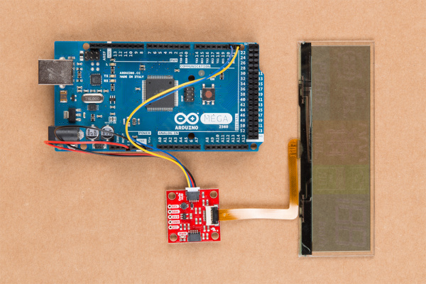
The Transparent OLED HUD requires quite a little bit of RAM (Around 5500 bytes) so you'll need to connect to your I2C pins directly to devices without Qwiic Shields. Connect yellow to SCL, blue to SDA, red to 3.3V and black to ground using the Qwiic jumper adapter cable to the respective pins of your board. In this case, we connected the board to an Arduino Mega 2560's I2C pins.

Connected to Mega

Transparent OLED HUD Attached to Arduino Mega

Library Overview

Note: This example assumes you are using the latest version of the Arduino IDE on your desktop. If this is your first time using Arduino, please review our tutorial on installing the Arduino IDE. If you have not previously installed an Arduino library, please check out our installation guide.

First, you'll need the SparkFun Transparent OLED HUD Arduino library. You can obtain this library through the Arduino Library Manager. Search for Sparkfun Wisechip HUD to install the latest version. If you prefer downloading the libraries from the GitHub repository and manually installing it, you can grab them here:

Before we get started developing a sketch, let's look at all of the functions we can use to control segments on the transparent HUD. The below code initializes the functions for the individual segments in the compass circle (CCx() functions), compass arrows (D0x() functions), tire pressure indication, destination distance(H01(), K01(), M01() for hours, kilometers, and meters), turn distance (K02() and M03() for kilometers and meters), the phone and TPMS icons (P0x() and T0x()) and finally, the 1's on the speedometer and compass (S01_BAR() and S15_BAR()). You won't need to use most of these functions, as most are used in higher level functions like setSpeedometer(), but we've given you access to these segments anyway. Turning any segmetn on is as simple as calling it with an argument of 1. Calling with a 0 will turn it off.

language:c
void D01(uint8_t Action);
void CC1(uint8_t Action);
void D02(uint8_t Action);
void CC2(uint8_t Action);
void D03(uint8_t Action);
void CC3(uint8_t Action);
void D04(uint8_t Action);
void CC4(uint8_t Action);
void D05(uint8_t Action);
void CC5(uint8_t Action);
void D06(uint8_t Action);
void CC6(uint8_t Action);
void D07(uint8_t Action);
void CC7(uint8_t Action);
void D08(uint8_t Action);
void CC8(uint8_t Action);
void D0x(uint8_t Action);
void C01(uint8_t Action);
void C02(uint8_t Action);
void H01(uint8_t Action);
void K01(uint8_t Action);
void M01(uint8_t Action);
void C03(uint8_t Action);
void K02(uint8_t Action);
void M03(uint8_t Action);
void P01(uint8_t Action);
void P02(uint8_t Action);
void P03(uint8_t Action);
void T01(uint8_t Action);
void T02(uint8_t Action);
void S01_BAR(uint8_t Action);
void S15_BAR(uint8_t Action);

Higher Level Functions

The available functions for the transparent OLED can be more easily seen in the below photo.

Segment Map

Segment Map. Click to enlarge.

All of the below functions will set a group of segments based on the argument passed into them

  • void compassCircle(uint8_t Select);
    • 0: All Off
    • 1-8: All Off Except Selected
    • 9: All On
    • 10-17: All On Except Selected
  • void compassArrows(uint8_t Select); --- Same as compass circle.
  • void radarDistanceUnits(uint8_t Action); --- turns on the m for radar distance.
  • void flag(uint8_t Action); --- Turns on the flag segment.
  • void tirePressureAlert(uint8_t Action); --- Displays TPMS text.
  • void speedometerUnits(uint8_t Action); --- Displays KM/H segments.
  • void destinationDistanceUnits(uint8_t iconUnits);
    • 0: Blank
    • 1: h
    • 2: m
    • 3: km
  • void turnDistanceUnits(uint8_t iconUnits);
    • 0: Blank
    • 1: m
    • 2: km

The following functions display the road and tunnel segments, pass in a 1 to turn the segment on.

  • void leftTunnel(uint8_t Action);
  • void middleTunnel(uint8_t Action);
  • void rightTunnel(uint8_t Action);
  • void leftRoad(uint8_t Action);
  • void middleRoad(uint8_t Action);
  • void rightRoad(uint8_t Action);

The following functions turn on the corresponding segments for the navigation

  • void nav_Group(uint8_t Action); --- Triggers the whole nav group
  • void nav_KeepLeft(uint8_t Action);
  • void nav_TurnLeft(uint8_t Action);
  • void nav_TurnRight(uint8_t Action);
  • void nav_HardRight(uint8_t Action);
  • void nav_HardLeft(uint8_t Action);
  • void nav_UTurnLeft(uint8_t Action);
  • void nav_UTurnRight(uint8_t Action);
  • void nav_ContinueStraight(uint8_t Action);
  • void nav_KeepRight(uint8_t Action);

  • void radarDetector(uint8_t Level);

    • 0: No Radar Gun Icon
    • 1: Radar Gun Only
    • 2-8: Distance Meter
  • void setHeading(uint8_t SpeedNo); --- Set's the compass heading. Maximum of 199.
  • void setDestinationDistance(uint16_t SpeedNo, uint8_t Mode); --- Set's the distance in the destination segments. Maximum of 999.
  • void setRadarDistance(uint16_t SpeedNo, uint8_t Mode); --- Set's the distance in the radar segments. Maximum of 999.
  • void setTurnDistance(uint16_t SpeedNo, uint8_t Mode); --- Set's the turn distance. Maximum of 999.
  • void setTirePressure(uint8_t SpeedNo, uint8_t Mode); --- Set the tire pressure. Maximum of 99
  • void setSpeedometer(uint8_t SpeedNo); --- Set the speedometer. Maximum of 199.
  • void setCallIcon(uint8_t iconStatus);

    • 0: Blank
    • 1: Outline
    • 2: Outline + Phone
    • 3: All Segments
  • void clearAll(void); --- Clears all segments.

Example Code

Now that we have our library installed and we understand the basic functions, let's run some examples for our Qwiic Transparent OLED HUD to see how it behaves.

Example 1 - All Segments

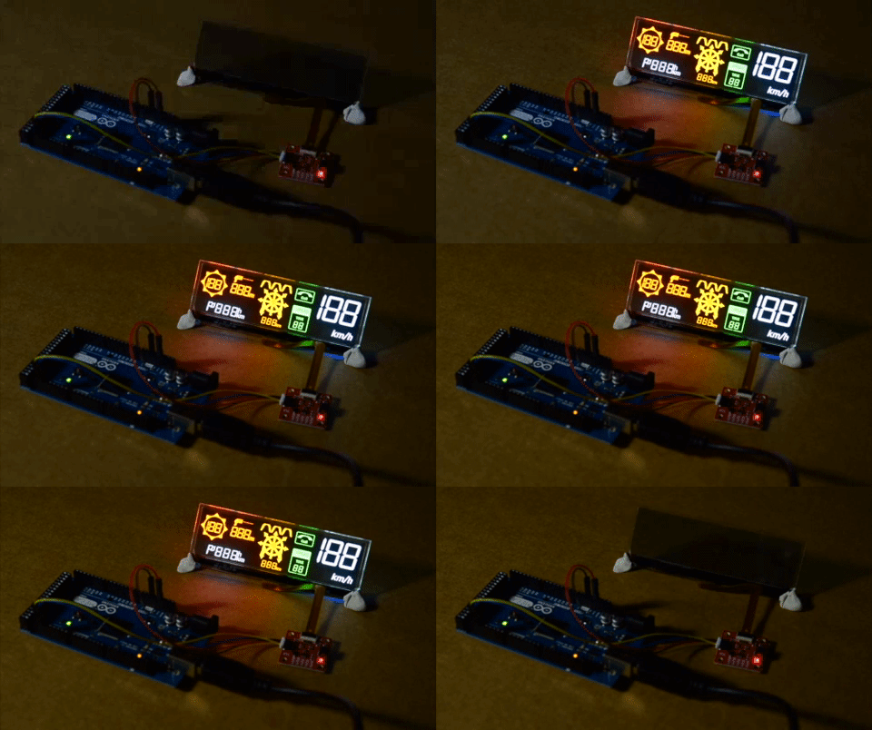
To get started with the first example, open up File>Examples>Examples from Custom Libraries>SparkFun WiseChip HUD>Example1_AllSegments. In this example, we begin by creating a WiseChipHUD object called myHUD and then initializing our sensor object in the setup() loop. The code to do this is shown below.

language:c
#include <WiseChipHUD.h>

WiseChipHUD myHUD;

void setup() {

  myHUD.begin();

}

Once we've initialized our HUD, we can start turning segments on. The main loop simply goes through and calls all of our available functions.

language:c
void loop() {

  myHUD.clearAll(); // Clears all of the segments

  /************************* Compass Group *************************/
  myHUD.compassCircle(9); // 0 = All Off; 1-8 = All Off Except Selected; 9 = All On; 10-17 = All On Except Selected
  myHUD.compassArrows(9); // 0 = All Off; 1-8 = All Off Except Selected; 9 = All On; 10-17 = All On Except Selected
  myHUD.setHeading(188);  // Max 199

  /************************* Radar Detector Group *************************/
  myHUD.radarDetector(8); // 0 = No Radar Gun Icon; 1 = Radar Gun Only; 2-8 = Distance Meter
  myHUD.setRadarDistance(888,0); // Max 999    
  myHUD.radarDistanceUnits(1); // 0 = Blank; 1 = "m" 

  /************************* Destination/Waypoint Group *************************/
  myHUD.flag(1); // 0 = Blank; 1 = flag icon 
  myHUD.setDestinationDistance(888,2); // Max 999
  myHUD.destinationDistanceUnits(3); // 0 = Blank; 1 = "h"; 2 = "m"; 3 = "km"
  myHUD.H01(1); // 0 = Blank; 1 = "h"

  /************************* Exit Group *************************/
  myHUD.leftTunnel(1); // 0 = Blank; 1 = Tunnel; Also try leftRoad();
  myHUD.middleTunnel(1); // 0 = Blank; 1 = Tunnel; Also try middleRoad();
  myHUD.rightTunnel(1); // 0 = Blank; 1 = Tunnel; Also try rightRoad();

  /************************* Navigation Group *************************/
  myHUD.nav_Group(1); // 0 = Entire Nav Group Off; 1 = Entire Nav Group On
  myHUD.setTurnDistance(888,1); // Max 999
  myHUD.turnDistanceUnits(2); // 0 = Blank; 1 = "m"; 2 = "km"
  // Turn Groups:
  // nav_KeepLeft(1);
  // nav_TurnLeft(1);
  // nav_HardLeft(1);
  // nav_UTurnLeft(1);
  // nav_ContinueStraight(1);
  // nav_KeepRight(1);
  // nav_TurnRight(1);
  // nav_HardRight(1);
  // nav_UTurnRight(1);

  /************************* Call Group *************************/
  myHUD.setCallIcon(3); // 0 = Blank; 1 = Outline; 2 = Outline + Phone Icon; 3 = All Segments

  /************************* TPMS Group *************************/
  myHUD.tirePressureAlert(3); // 0 = Blank; 1 = "TPMS"; 2 = "TIRE"; 3 = All Segments
  myHUD.setTirePressure(88,1); // Max 99

  /************************* Speedometer Group *************************/
  myHUD.setSpeedometer(188); // Max 199
  myHUD.speedometerUnits(1); // 0 = Blank; 1 = "km/h"

  delay(5000);

  myHUD.clearAll(); // Clears all of the segments

while(1){};

}

If you have not already, select the Arduino/Genuino Mega 2560 or Mega2560 as the board, COM port that it enumerated on, and hit upload! The OLED should look something like the below GIF.

Example 1 Output

Example 1 Output

Example 2 - Animated Icons

In the second example, we'll animate our display segments. To get started with the second example, open up File>Examples>Examples from Custom Libraries>SparkFun WiseChip HUD>Example2_AnimatedIcons. We initialize our HUD the exact same as we do in the first example. Then, we go ahead and use for loops to loop through each possible state of a group of segments to animate it. Each loop starts at 0 and goes to the maximum number of options for that particular group of segments. There is a small delay in each loop to allow for some time between frames.. We do this for the compass, radar, phone and TPMS icons. We clear the entire HUD in between each animation of a group of segments to ensure that we are only displaying one group at a time. The code that accomplishes this is shown below.

language:c
void loop() {

  myHUD.clearAll(); // Clears all of the segments

  for(int j = 0; j < 2; j++){
    for(int i = 1; i < 9; i++){
      myHUD.compassCircle(i);
      delay(50);
    }
  }

  for(int j = 0; j < 2; j++){
    for(int i = 10; i < 18; i++){
      myHUD.compassCircle(i);
      delay(50);
    }
  }

  myHUD.compassCircle(0);

  for(int j = 0; j < 2; j++){
    for(int i = 1; i < 9; i++){
      myHUD.compassArrows(i); 
      delay(100);
    }
  }

  for(int j = 0; j < 2; j++){
    for(int i = 10; i < 18; i++){
      myHUD.compassArrows(i); 
      delay(100);
    }
  }

  myHUD.compassArrows(0); 

  for(int i = 0; i < 5; i++){
    myHUD.radarDetector(1); 
    delay(100);
    myHUD.radarDetector(0);
    delay(100);
  }

  myHUD.radarDistanceUnits(1);

  for(int j = 800; j >= 0; j = j - 10){
    myHUD.setRadarDistance(j,0); 
    myHUD.radarDetector(j/100);
  }

  myHUD.clearAll();

  for(int j = 0; j < 5; j++){
    for(int i = 0; i < 4; i++){
      myHUD.setCallIcon(i); 
      delay(100);
    }
  }

  myHUD.setCallIcon(0); 

  myHUD.tirePressureAlert(3);
  myHUD.setTirePressure(30,1); 
  delay(2000);

  for(int j = 30; j > 14; j--){ 
    myHUD.setTirePressure(j,1); 
    delay(random(100,1000));
  }

  for(int j = 0; j < 10; j++){
    for(int i = 1; i < 3; i++){
      myHUD.tirePressureAlert(i);
      delay(100);
    }
  }
  myHUD.tirePressureAlert(3);

  myHUD.clearAll();

while(1){};

}

If you have not already, select the Arduino/Genuino Mega 2560 or Mega2560 as the board, COM port that it enumerated on, and hit upload! The transparent HUD should look something like the below GIF after uploading the code.

Example 2 Output

Example 2 Output

Example 3 - Counting

In the third example, we'll have each of the available number displays count up to 200. To get started with the third example, open up File>Examples>Examples from Custom Libraries>SparkFun WiseChip HUD>Example2_AnimatedIcons. In this example, we initialize the OLED the same way we have been doing in our previous two examples. Then, in our void loop(), we clear the HUD, then begin a for loop that counts by 5's. We write the value of the index variable to each of the segments. The code that accomplishes this is shown below.

language:c
void loop() {

  myHUD.clearAll(); // Clears all of the segments

  while (1) {

    for (int i = 0; i < 200; i += 5) {
      myHUD.setHeading(i);  // Max 199
      myHUD.setRadarDistance(i, 0); // Max 999
      myHUD.setDestinationDistance(i, 2); // Max 999
      myHUD.setTurnDistance(i, 1); // Max 999
      myHUD.setTirePressure(i, 1); // Max 99
      myHUD.setSpeedometer(i); // Max 199
      delay(200);
    }

    myHUD.clearAll();

  };

}

If you have not already, select the Arduino/Genuino Mega 2560 or Mega2560 as the board, COM port that it enumerated on, and hit upload! Uploading this code should make the OLED look like the below GIF. Notice how the number for the TPMS stops at 99. This is a demonstration of how these functions handle out of bounds numbers.

Example 3 Output

Example 3 Output

Resources & Going Further

Now that you've successfully got your Qwiic Transparent OLED HUD Hookup Guide up and running, it's time to incorporate it into your own project!

For more information, check out the resources below:

Need some inspiration for your next project? Check out some of these related tutorials:

Micro OLED Breakout Hookup Guide

Learn how to hook up the Micro OLED breakout to an Arduino. Then draw pixels, shapes, text and bitmaps all over it!

Photon OLED Shield Hookup Guide

The Photon OLED Shield has everything you need to add a small yet crisp OLED screen to your Photon projects. This hookup guide will show you how to get started.

TeensyView Hookup Guide

A guide to using the TeensyView OLED board to display text and graphics.

Flexible Grayscale OLED Hookup Guide

Figure out how to get images displaying on your new flexible OLED screen.

learn.sparkfun.com | CC BY-SA 3.0 | SparkFun Electronics | Niwot, Colorado

Qwiic Proximity Sensor (VCNL4040) Hookup Guide

$
0
0

Qwiic Proximity Sensor (VCNL4040) Hookup Guide a learn.sparkfun.com tutorial

Available online at: http://sfe.io/t864

Introduction

The Qwiic Proximity Sensor is a simple IR presence and ambient light sensor utilizing the VCNL4040. This sensor is excellent for detecting if something has appeared in front of the sensor; detecting objects qualitatively up to 20cm away. This means you can detect if something is there, and if it is closer or further away since the last reading, but it’s difficult to say it is 7.2cm away. If you need quantitative distance readings for exact distances, check out the SparkFun 2 meter and 4 meter Time of Flight (ToF) sensors with mm accuracy.

SparkFun Proximity Sensor Breakout - 20cm, VCNL4040 (Qwiic)

SparkFun Proximity Sensor Breakout - 20cm, VCNL4040 (Qwiic)

SEN-15177
$6.95

We often see this type of sensor on automatic towel dispensers, automatic faucets, etc. However, the VCNL4040 has no dead zone and can read all the way up to the face of the sensor. The SparkFun Proximity VCNL4040 sensor is a great digital alternative to the popular analog PIR sensors. The Qwiic Proximity Sensor also has an ambient light sensor built it which is excellent if you need a digital light sensor for your next glitter cannon.

This board is one of our many Qwiic compatible boards! Simply plug and go. No soldering, no figuring out which is SDA or SCL, and no voltage regulation or translation required!

Required Materials

The Qwiic Proximity Sensor does need a few additional items for you to get started. You may already have a few of these items, so feel free to modify your cart as necessary.

SparkFun RedBoard Qwiic

SparkFun RedBoard Qwiic

DEV-15123
$19.95
SparkFun Qwiic Cable Kit

SparkFun Qwiic Cable Kit

KIT-15081
$7.95

Suggested Reading

If you're unfamiliar with jumper pads or I2C be sure to checkout some of these foundational tutorials.

I2C

An introduction to I2C, one of the main embedded communications protocols in use today.

How to Work with Jumper Pads and PCB Traces

Handling PCB jumper pads and traces is an essential skill. Learn how to cut a PCB trace, add a solder jumper between pads to reroute connections, and repair a trace with the green wire method if a trace is damaged.

If you aren't familiar with the Qwiic system, we recommend reading here for an overview.

Qwiic Connect System

Hardware Overview

Note: If you want to do anything outside of what is covered in this tutorial or the example code, please refer to the VCNL4040 datasheet for exact details on the sensor functionality.

Power LED

There is a power status LED to help make sure that your Qwiic Joystick is getting power. You can power the board either through the polarizedQwiic connector system or the breakout pins (PWR and GND) provided. This Qwiic system is meant to use 3.3V, be sure that you are NOT using another voltage when using the Qwiic system.

Power LED

VCNL4040 Sensor

The VCNL4040 is a proximity sensor (PS), ambient light sensor (ALS), and a high power IR emitter (IRED) integrated into a single package. The ambient light sensor and proximity sensor operate in a parallel structure. The combination of the two sensors along with the IR emitter form the proximity detector.

VCNL4040 Sensor

The sensor has an operating voltage range from 2.5V to 3.6V. It is recommended that you use this board with the intended 3.3V of the Qwiic connect system. The VCNL4040 also includes excellent temperature compensation. For any details not covered in this guide, please refer to the datasheet.

Note: This sensor is excellent for detecting qualitative changes (if an object is there or moved since the last reading). If you need quantitative distance readings, like exact distances, check out the SparkFun 2 meter and 4 meter Time of Flight (ToF) sensors with mm accuracy.

IR Emitter

The IR emmiter is immune to red glow with a 940 nm wavelength (for those discrete applications) and the sink current is programmable (200 mA default). For more details on the IR emitter, please refer to the datasheet.

Ambient Light Sensor (ALS)

The VCNL4040 offers a 16-bit high resolution ALS with ±10 % accuracy and is immune to fluorescent light flicker. With an ambient light sensing capability down to 0.01 lux/step, the VCNL4040 works well under a low transmittance lens design (dark lens). In addition, the patented FiltronTM technology offers great background light cancellation capability (including sunlight) without utilizing microcontroller resources.

Proximity Sensor (PS)

The proximity sensor features smart persistence, which prevents the misjudgment of proximity sensing but also keeps a fast response time. In active force mode, a single measurement can be requested for more design flexibility and/or power saving.

Qwiic or I2C

I2C Address

The sensor has a single slave address 0x60 (HEX) of 7-bit addressing, following I2C protocol.

Connections

The simplest way to use the Qwiic Proximity Sensor is through the Qwiic connect system. The connectors are polarized for the I2C connection and power. (*They are tied to their corresponding breakout pins.)

Qwiic Connectors

However, the board also provides five labeled breakout pins. You can connect these lines to the I2C bus of your microcontroller and power pins (3.3V and GND), if it doesn't have a Qwiic connector. The interrupt pin is broken out to use for triggered events.

Breakout Pins

Interrupt Pin

High and low interrupt thresholds can be programmed for both the ambient light sensor and proximity sensor, allowing the component to use a minimal amount of the microcontrollers resources. Adjustable persistence sets up the amount of consecutive hits required before an interrupt event occurs, to prevent false triggers.

The VCNL4040 also supports an easy to use proximity detection logic mode, that triggers when the PS high threshold is exceeded and automatically resets the interrupt pin when the proximity reading falls beneath the PS low threshold.

An interrupt can be cleared by reading data out from the INT_Flag register (resetting it to "0") and the INT pin is then reset to high. For more details on the interrupt, please refer to the datasheet.
Interrupt Jumper
Cutting the INT jumper will remove the 10 kΩ pull-up resistor from the INT pin.
Interrupt Jumper

I2C Pull-up Jumper

Cutting the I2C jumper will remove the 2.2 kΩ pull-up resistors from the I2C bus. If you have many devices on your I2C bus you may want to remove these jumpers. Not sure how to cut a jumper? Read here!

Pull-up Jumper

Hardware Assembly

With the Qwiic connector system, assembling the hardware is simple. All you need to do is connect your Qwiic Proximity Senor to the RedBoard Qwiic with a Qwiic cable. Otherwise, you can use the I2C pins, if you don't have a Qwiic enabled microcontroller. Just be away of your input voltage and any logic level shifting you may need to do.

Hardware connection

Arduino Library

Note: This example assumes you are using the latest version of the Arduino IDE on your desktop. If this is your first time using Arduino, please review our tutorial on installing the Arduino IDE. If you have not previously installed an Arduino library, please check out our installation guide.

We’ve written an Arduino library to flex every feature of this sensor. You can grab it from the Arduino Library Manager, from the GitHub repository, or use the download button below.

Library Functions

The Arduino library is commented and the functions should be self-explanatory. However, below is a detailed list of the available library functions.

Note: It is recommended that users begin with the examples in the following section before diving head first into the library functions. The library examples demonstrate how to setup the more basic features of the VCNL4040 without having to dig through the datasheet. Once users have become familiar with the basic setups and have gone through the datasheet thoroughly, it should be easier to follow the library functions below.

.begin - Check communication with sensor and set it to default I2C Wire library settings

.isConnected - Checks connection

.setLEDCurrent - Sets the IR LED sink current to one of 8 settings (75, 100, 120, 140, 160, 180, and 200 mA).

.setIRDutyCycle - Sets duty cycle of the IR LED (40 max.)

.setProxInterruptPersistance - Sets the Prox interrupt persistance value.
The PS persistence function (PS_PERS, 1, 2, 3, 4) helps to avoid false trigger of the PS INT. It defines the amount of consecutive hits needed in order for a PS interrupt event to be triggered..setAmbientInterruptPersistance - Sets the Ambient interrupt persistance value
The ALS persistence function (ALS_PERS, 1, 2, 4, 8) helps to avoid false trigger of the ALS INT. It defines the amount of consecutive hits needed in order for a ALS interrupt event to be triggered.

.setProxIntegrationTime - Sets the integration time for the proximity sensor
.setAmbientIntegrationTime - Sets the integration time for the ambient light sensor

.powerOnProximity - Power on the prox sensing portion of the device
.powerOffProximity - Power off the prox sensing portion of the device

.powerOnAmbient - Power on the ALS sensing portion of the device
.powerOffAmbient - Power off the ALS sensing portion of the device

.setProxResolution - Sets the proximity resolution to 12 or 16 bit

.enableAmbientInterrupts - Enables ALS interrupt
.disableAmbientInterrupts - Disables ALS interrupt

.enableSmartPersistance - Turn on smart presistance
.disableSmartPersistance - Turn off smart presistance
To accelerate the PS response time, smart persistence prevents the misjudgment of proximity sensing, but also keeps a fast response time.

.enableActiveForceMode - Enables active force mode
.disableActiveForceMode - Disable active force mode
An extreme power saving way to use PS is to apply PS active force mode. Anytime host would like to request one proximity measurement, enable the active force mode. This triggers a single PS measurement, which can be read from the PS result registers. VCNL4040 stays in standby mode constantly.

.takeSingleProxMeasurement - Sets trigger bit so sensor takes a force mode measurement and returns to standby.

.enableWhiteChannel - Enables the white measurement channel
.disableWhiteChannel - Disables the white measurement channel

.enableProxLogicMode - Enables the proximity detection logic output mode
.disableProxLogicMode - Disables the proximity detection logic output mode
When this mode is selected, the INT pin is pulled low when an object is close to the sensor (value is above high threshold) and is reset to high when the object moves away (value is below low threshold). Register: PS_THDH / PS_THDL define where these threshold levels are set.

.setProxCancellation - Sets the proximity sensing cancellation value - helps reduce cross talk with ambient light

.setALSHighThreshold - Value that ALS must go above to trigger an interrupt
.setALSLowThreshold - Value that ALS must go below to trigger an interrupt

.setProxHighThreshold - Value that Proximity Sensing must go above to trigger an interrupt
.setProxLowThreshold - Value that Proximity Sensing must go below to trigger an interrupt

.getProximity - Read the Proximity value
.getAmbient - Read the Ambient light value
.getWhite - Read the White light value
.getID - Read the sensors ID

.setProxInterruptType - Enable four proximity interrupt types
.isClose - Interrupt flag: True if prox value greater than high threshold
.isAway - Interrupt flag: True if prox value lower than low threshold
.isLight - Interrupt flag: True if ALS value higher than high threshold
.isDark - Interrupt flag: True if ALS value lower than low threshold

.readCommand - Reads two consecutive bytes from a given 'command code' location
.writeCommand - Write two bytes to a given command code location (8 bits)

Arduino Examples

Note: This section is an example of using the Qwiic Proximity Sensor and the RedBoard Qwiic with the Arduino IDE. It is not intended to be a guide for using I2C devices with the Arduino IDE.

Please use the following links and the internet for a better understanding of I2C and how it works in the Arduino IDE:

Example 1: Proximity Readings

This example outputs the IR Proximity Value from the VCNL4040 sensor in the Serial Monitor.

Serial output of proximity values

Despite being a qualitative sensor, you will notice that the output does vary with the distance of the object, surface color, and reflectivity. You can also use this setting to estimate the field of view of the sensor. The maximum output value is 65535, closest to the sensor, and the minimum (0-1) being the furthest the sensor can read.

Example 2: Is Something There

This example takes an initial reading at power on. If the reading changes by a significant amount the sensor prints that something is present in the Serial Monitor.

Serial output of proximity detection

This example also allows the proximity sensor to work as a dual purpose photogate.

Hot wheels car triggering proximity sensor

A Hot WheelsTM car triggering proximity sensor.
(*The speed of the Gif is slowed down for you to see the output in the Serial Monitor.)

There is a slight delay in the serial output from the microcontroller (few frames); however, this is exaggerated due to how the image is slowed down.

Example 3: Ambient Light

This example outputs ambient light readings to the terminal.

Serial output of ambient light values

Again the sensor is qualitative, but you can test how the angle of incident from the light source affects the sensor readings.

Example 4: All Readings

This example outputs IR, ambient and white light readings to the terminal. Along with proximity and ambient light sensing the VCNL4040 has a 'white light' sensor as well.

Serial output of all values

Example 5: Advanced Settings

This example shows how to use different Wire ports, fast I2C, and various advanced settings that are supported by the library. Please, refer to the datasheet and library functions listed above for more details.

Resources and Going Further

For more information, check out the resources below:

Need help getting started with Arduino and I2C? Check out these resources here:

Need some inspiration for your next project? Check out some of these other Qwiic product tutorials:

IoT Power Relay

Using the ESP32 to make a web-configured timed relay.

Qwiic Flex Glove Controller Hookup Guide

Is your finger bent? Is your finger straight? The Qwiic Flex Glove controller board will answer this age old question for you with the flex sensor!

Qwiic IR Array (MLX90640) Hookup Guide

The Melexis MLX90640 contains a 32x24 array of thermopile sensors creating, in essence, a low resolution thermal imaging camera. In this guide, we’ll go over how to connect your Qwiic Infrared Array with MLX90640 and get it communicating with Processing to produce a nice thermal image.

RedBoard Qwiic Hookup Guide

This tutorial covers the basic functionality of the RedBoard Qwiic. This tutorial also covers how to get started blinking an LED and using the Qwiic system.

learn.sparkfun.com | CC BY-SA 3.0 | SparkFun Electronics | Niwot, Colorado
Transparent Graphical OLED Breakout Hookup Guide

$
0
0

Transparent Graphical OLED Breakout Hookup Guide a learn.sparkfun.com tutorial

Available online at: http://sfe.io/t612

Introduction

The future is here! You asked and we delivered - our Qwiic Transparent Graphical OLED Breakout allows you to display custom images on a transparent screen using either I2C or SPI connections.

With Qwiic connectors it's quick (ha ha) and easy to get started with your own images. However, we still have broken out 0.1"-spaced pins in case you prefer to use a breadboard. Brilliantly lit in the dark and still visible by daylight, this OLED sports a display area of 128x64 pixels, 128x56 of which are completely transparent. Control of the OLED is based on our new HyperDisplay library.

SparkFun Transparent Graphical OLED Breakout (Qwiic)

SparkFun Transparent Graphical OLED Breakout (Qwiic)

LCD-15173
$39.95

The Arduino sketch required to drive this display requires quite a bit of dynamic memory, meaning that it is not going to fit on a smaller controller like an ATmega328. Any controller with larger RAM should have no problem. In this tutorial, we're using the ESP32 Thing Plus.

Required Materials

To follow along with this tutorial, you will need the following materials. You may not need everything, depending on what you have. Add it to your cart, read through the guide, and adjust the cart as necessary.

Tools

If you want to use the broken out GPIO pins along the bottom of the board, you'll need to solder some headers to them so you'll need a soldering iron, solder, and general soldering accessories.

Solder Lead Free - 100-gram Spool

Solder Lead Free - 100-gram Spool

TOL-09325
$7.95
7
Weller WLC100 Soldering Station

Weller WLC100 Soldering Station

TOL-14228
$44.95

Suggested Reading

If you aren't familiar with the Qwiic system, we recommend reading here for an overview.

Qwiic Connect System

We would also recommend taking a look at the following tutorials if you aren't familiar with them.

Serial Communication

Asynchronous serial communication concepts: packets, signal levels, baud rates, UARTs and more!

I2C

An introduction to I2C, one of the main embedded communications protocols in use today.

Serial Terminal Basics

This tutorial will show you how to communicate with your serial devices using a variety of terminal emulator applications.
New!

ESP32 Thing Plus Hookup Guide

Hookup guide for the ESP32 Thing Plus using the WiFi/Bluetooth system-on-chip in Arduino.
New!

Everything You Should Know About HyperDisplay

This is a tutorial to go in-depth about the SparkFun HyperDisplay Arduino Library.

Hardware Overview

Let's check out some of the characteristics of the Qwiic we're dealing with, so we know what to expect out of the board.

CharacteristicRange
Operating Voltage1.65V-3.3V
Supply Current400 mA
I2C Addresses0x30 (Default), 0x31

Graphical Display

The graphical display is where all the fun stuff happens. The glass itself measures 42mm x 27.16mm, with a pixel display that is 35.5 x 18mm. It houses 128x64 pixels, 128x56 of which are transparent.

Display Screen

Graphical Display

Qwiic Connectors

There are two Qwiic connectors on the board such that you can daisy-chain the boards should you choose to do so. If you're unfamiliar with our Qwiic system, head on over to our Qwiic page to see the advantages!

Qwiic Connectors

Qwiic Connectors

GPIO Pins

When you look at the GPIO pins, you'll notice that the labels are different from one side to the other. One side is labeled for I2C, the other side is labeled for SPI.


I2C LabelsSPI Labels

Power LED

This bad boy will light up when the board is powered up correctly.

Power LED

Power LED

You can disable the power LED by cutting the LED jumpers on the back of the board.

Power LED Jumpers

Power LED Jumpers

JPX Jumpers

The JPX jumpers are used to either change the I2C address or configure the board to use SPI communications. The other two jumpers allow you to disconnect the power LED and to disconnect the I2C pull-up resistors when chaining several Qwiic devices.

JumperFunction
JP1Holds the Chip Select line low when closed. Close for I2C, open for SPI
JP2Selects the address in I2C mode. Closed for 0x30 by default and open for 0x31. Open for SPI mode to release the D/C pin
JP3Used to select I2C or SPI mode. Close for I2C, open for SPI
JP4This jumper should be closed for I2C and open for SPI. This connection allows SDA to be bi-directional

JP1-JP4

JPX Jumpers

I2C Pull-Up Jumper

I2C devices contain open drains so we include resistors on our boards to allow these devices to pull pins high. This becomes a problem if you have a large number of I2C devices chained together. If you plan to daisy chain more than a few Qwiic boards together, you'll need to cut this I2C pull-up jumper.

I2C Pullup jumper

I2C PU Jumpers

Hardware Hookup

Now that you know what's available on your breakout board we can check out the options for connecting it to the brains of your project. There are two options to use - either I2C or SPI - and they each have their own advantages and drawbacks. Read on to choose the best option for your setup.

I2C (Qwiic)

The easiest way to start using the Transparent Graphical OLED is to use a Qwiic Cable along with a Qwiic compatible microcontroller (such as the ESP32 Thing Plus). You can also use the Qwiic Breadboard Cable to attach any I2C capable microcontroller, or take the scenic route and solder in all the I2C wires to the plated-through connections on the board.

Qwiic ConnectorI2C Pinout

So why use I2C? It's easy to connect with the Qwiic system, and you can put up to two of the Transparent Graphical Breakouts on the same bus without using any more microcontroller pins. That simplicity comes at a cost to performance though. The maximum clock speed of the I2C bus is 400 kHz, and there is additional overhead in data transmission to indicate which bytes are data and which are commands. This means that the I2C connection is best for showing static images.

Breakout PinMicrocontroller Pin Requirements
GNDGround pin. Connect these so the two devices agree on voltages
3V33.3V supply pin, capable of up to 400 mA output
SDASDA - the bi-directional data line of your chosen I2C port
SCLSCL - the clock line of your chosen I2C port
SA0Optional : change the I2C address of the breakout. Make sure to cut JP2
RSTOptional : reset the breakout to a known state by pulsing this low

SPI

SPI solves the I2C speed problems. With SPI there is a control signal that indicates data or command and the maximum clock speed is 10 MHz -- giving SPI 50x more speed! However, it doesn't have the same conveniences of the polarized Qwiic connector and low pin usage. You'll need to solder to the pins.

SPI Pinout

You can use SPI to connect as many breakouts as you want. For N displays you will need to use at least N + 3 data pins. That's because the MOSI, SCLK, and D/C pins can be shared between displays but each breakout needs its own dedicated Chip Select (CS) pin.

Breakout PinMicrocontroller Pin Requirements
CSA GPIO pin, set low when talking to the breakout
D/CA GPIO pin, indicates if bytes are data or commands
SCLKThe clock output of your chosen SPI port
MOSIThe data output of your chosen SPI port
3V33.3V supply pin, capable of up to 400 mA output
GNDGround pin. Connect these so the two devices agree on voltages

Software Setup and Programming

Note: This example assumes you are using the latest version of the Arduino IDE on your desktop. If this is your first time using Arduino, please review our tutorial on installing the Arduino IDE. If you have not previously installed an Arduino library, please check out our installation guide.

Drivers and Board Add-Ons

Depending on your development board, you may need to install drivers and a board add-on. For the scope of this tutorial, we will be using the ESP32 Thing Plus. If you have not already, make sure that you install the drivers and ESP32 Arduino core files as explained in our ESP32 Thing Plus Hookup Guide.

Installing ESP32 Board Add on Files
Software Setup for the ESP32

Arduino Libraries

The software for the Transparent Graphical OLED Breakout is built on the HyperDisplay libraries developed by SparkFun. If you are unfamiliar with how this abstracted library works, head over to our Everything You Should Know About HyperDisplay tutorial.

New!

Everything You Should Know About HyperDisplay

February 20, 2019

This is a tutorial to go in-depth about the SparkFun HyperDisplay Arduino Library.

HyperDisplay is an abstracted library that requires multiple layers in order to function correctly. For the Transparent Graphical OLED to work, you'll need our base HyperDisplay Library, the HyperDisplay SSD1309 Arduino Library, and the somewhat painfully but informatively named HyperDisplay UG2856KLBAG01 Arduino Library. You can obtain these libraries through the Arduino Library Manager by searching for "HyperDisplay Library", "HyperDisplay SSD1309", "HyperDisplay Transparent Graphical OLED", respectively. You can download the required libraries from their individual GitHub pages or download the following *.zip file that contains all three libraries to manually install:

If you are manually downloading the libraries, unzip them and copy all three libraries to your Arduino>Libraries folder, wherever that may be located on your machine.

Copy the HyperDisplay libraries to your Arduino Libraries folder

Having a hard time seeing? Click the image for a closer look.

Examples

Included in the HyperDisplay_UG2856KLBAG01_ArduinoLibrary are three examples to help you get started using the Transparent Graphical OLED Breakout. If you haven't already downloaded the libraries from the afore-mentioned locations, click on the button below to download the library bundle. Unzip and copy it into your Arduino>Libraries folder.

If you are following along with this tutorial using an ESP32 Thing Plus board (as we are), make sure you set your board definition to Adafruit ESP32 Feather.

Choose The Adafruit Feather Board Definition

Example 1: DisplayTest

The purpose of this example is to act like the "Hello World" message for your display. Uploading this sketch will help confirm that you have followed the hardware hookup correctly. The sketch runs through a couple of different display test, beginning with a custom SparkFun logo display.

To show the logo, Owen whipped up a quick python script that looks at a jpg image and writes out, pixel by pixel, a function to make the display. We've included his script and our image here--have a look! With just a little modification it could be useful in your own application.

To get started, either select File>Examples>SparkFun HyperDisplay Transparent Graphical OLED Library>Example1_DisplayTest or copy and paste the code below into a new Arduino window.

language:c
/*
  Verify that your Qwiic Transparent Grahical OLED is connected correctly and working.

  By: Owen Lyke
  SparkFun Electronics
  Date: February 26, 2019
  License: MIT. See license file for more information but you can
  basically do whatever you want with this code.
  Feel like supporting open source hardware?
  Buy a board from SparkFun! https://www.sparkfun.com/products/15173


  The graphics library is like a 3-layer cake. Here they are from top-down
  https://github.com/sparkfun/SparkFun_HyperDisplay
  https://github.com/sparkfun/HyperDisplay_SSD1309_ArduinoLibrary
  https://github.com/sparkfun/HyperDisplay_UG2856KLBAG01_ArduinoLibrary

  Hardware Compatibility
    - The IO pins on this board are designed for use with 3.3V so if you are using a 5V microcontroller
      please use a level shifter. Note: Qwiic connectors on SparkFun dev boards are already at 3.3V
    - This display relies on a copy of graphics data in your microcontroller, a total of 1024 bytes. 
      That is half the RAM available on an Uno so it is easy to run into sinister low-memory related
      bugs. We reccomend using a micro with more memory like a SAMD21, Esp32, Teensy, etc.

  Hardware Connections:
  Option 1 (I2C):
    Connect using a Qwiic jumper if you have a Qwiic compatible board and you plan to use I2C

  Option 2 (SPI):
    Connect SCLK and MOSI to the SPI port of your choice (13 and 11 for SPI on Uno-like boards) 
    Also connect D/C and CS to two unused GPIO pins of your choice (and set the proper pin definitions below)
    Don't forget power - connect 3.3V and GND
*/

#include "HyperDisplay_UG2856KLBAG01.h"   // Your library can be installed here: http://librarymanager/All#SparkFun_Transparent_Graphical_OLED
                                          // The rest of the Layer Cake:         http://librarymanager/All#SparkFun_HyperDisplay_SSD1309
                                          //                                     http://librarymanager/All#SparkFun_HyperDisplay
//////////////////////////
//      User Setup      //
//////////////////////////
#define SERIAL_PORT Serial  
#define WIRE_PORT Wire      // Used if USE_SPI == 0
#define SPI_PORT SPI        // Used if USE_SPI == 1

#define RES_PIN 2           // Optional
#define CS_PIN 4            // Used only if USE_SPI == 1
#define DC_PIN 5            // Used only if USE_SPI == 1

#define USE_SPI 1           // Choose your interface. 0 = I2C, 1 = SPI

// END USER SETUP


// Object Declaration. A class exists for each interface option
#if USE_SPI
  UG2856KLBAG01_SPI myTOLED;  // Declare a SPI-based Transparent OLED object called myTOLED
#else
  UG2856KLBAG01_I2C myTOLED;  // Declare a I2C-based Transparent OLED object called myTOLED
#endif /* USE_SPI */


void setup() {
  Serial.begin(9600);

  Serial.println(F("Example1_DisplayTest: Transparent Graphical OLED"));

#if USE_SPI 
  SPI_PORT.begin();
  myTOLED.begin(CS_PIN, DC_PIN, SPI_PORT);                  // Begin for SPI requires that you provide the CS and DC pin numbers
#else
  WIRE_PORT.begin();
  myTOLED.begin(WIRE_PORT, false, SSD1309_ARD_UNUSED_PIN);  // Begin for I2C has default values for every argument
  Wire.setClock(400000);
#endif /* USSE_SPI */

// Don't show the logo on boards with small memory
#if !defined(__AVR_ATmega328P__) && !defined(__AVR_ATmega168__)
  showLogo( );      // The showLogo function is a hacky way to get a large bitmap into program space without using <avr/pgspace.h>
#endif
}

void loop() {

  lineTest();
  delay(500);

  rectTest();
  delay(500);

  circleTest();
  delay(500);
}

void lineTest( void )
{
  myTOLED.clearDisplay();

  for(hd_hw_extent_t indi = 0; indi < myTOLED.xExt; indi+=5)
  {
    myTOLED.lineSet(0,0,indi,myTOLED.yExt-1,1);
    delay(10);
  }

  for(hd_hw_extent_t indi = 0; indi < myTOLED.yExt; indi+=5)
  {
    myTOLED.lineSet(0,myTOLED.yExt-1,myTOLED.xExt-1,myTOLED.yExt-indi-1,1);
    delay(10);
  }

  for(hd_hw_extent_t indi = 0; indi < myTOLED.xExt; indi+=5)
  {
    myTOLED.lineSet(myTOLED.xExt-1,myTOLED.yExt-1,myTOLED.xExt-indi-1,0,1);
    delay(10);
  }

  for(hd_hw_extent_t indi = 0; indi < myTOLED.yExt; indi+=5)
  {
    myTOLED.lineSet(myTOLED.xExt-1,0,0,indi,1);
  }
}

void rectTest( void )
{
  myTOLED.clearDisplay();

  for(uint8_t indi = 0; indi < myTOLED.yExt/2; indi+=1)
  {
    myTOLED.rectangleSet(myTOLED.xExt/2-1-indi, myTOLED.yExt/2-1-indi, myTOLED.xExt/2+1+indi, myTOLED.yExt/2+1+indi, false);
    delay(50);
  }

  for(uint8_t indi = 0; indi < myTOLED.yExt/2; indi+=1)
  {
    myTOLED.rectangleClear(myTOLED.xExt/2-1-indi, myTOLED.yExt/2-1-indi, myTOLED.xExt/2+1+indi, myTOLED.yExt/2+1+indi, false);
    delay(50);
  }

  for(uint8_t indi = 0; indi < myTOLED.yExt/2; indi+=1)
  {
    myTOLED.rectangleSet(myTOLED.xExt/2-1-indi, myTOLED.yExt/2-1-indi, myTOLED.xExt/2+1+indi, myTOLED.yExt/2+1+indi, false);
    delay(50);
  }
}

void circleTest( void )
{
  myTOLED.clearDisplay();

  for(uint8_t indi = 0; indi < (myTOLED.xExt/2 - 1); indi++)
  {
    myTOLED.circleSet((myTOLED.xExt/2 - 1),(myTOLED.yExt/2 - 1), indi, false);
    delay(10);
  }
  myTOLED.circleSet((myTOLED.xExt/2 - 1),(myTOLED.yExt/2 - 1), myTOLED.xExt/2, true);
}

#if !defined(__AVR_ATmega328P__) && !defined(__AVR_ATmega168__)
void showLogo( void ){
  myTOLED.setContrastControl(0);

  myTOLED.pixelSet(84, 3); myTOLED.pixelSet(85, 3); myTOLED.pixelSet(86, 3); myTOLED.pixelSet(87, 3); myTOLED.pixelSet(88, 3); 
  myTOLED.pixelSet(83, 4); myTOLED.pixelSet(84, 4); myTOLED.pixelSet(85, 4); myTOLED.pixelSet(86, 4); myTOLED.pixelSet(87, 4); 
  myTOLED.pixelSet(82, 5); myTOLED.pixelSet(83, 5); myTOLED.pixelSet(84, 5); myTOLED.pixelSet(85, 5); myTOLED.pixelSet(86, 5); 
  myTOLED.pixelSet(82, 6); myTOLED.pixelSet(83, 6); myTOLED.pixelSet(84, 6); myTOLED.pixelSet(85, 6); myTOLED.pixelSet(86, 6); 
  myTOLED.pixelSet(82, 7); myTOLED.pixelSet(83, 7); myTOLED.pixelSet(84, 7); myTOLED.pixelSet(85, 7); myTOLED.pixelSet(86, 7); 
  myTOLED.pixelSet(82, 8); myTOLED.pixelSet(83, 8); myTOLED.pixelSet(84, 8); myTOLED.pixelSet(85, 8); myTOLED.pixelSet(86, 8); myTOLED.pixelSet(87, 8); myTOLED.pixelSet(92, 8); 
  myTOLED.pixelSet(83, 9); myTOLED.pixelSet(84, 9); myTOLED.pixelSet(85, 9); myTOLED.pixelSet(86, 9); myTOLED.pixelSet(87, 9); myTOLED.pixelSet(88, 9); myTOLED.pixelSet(89, 9); myTOLED.pixelSet(91, 9); myTOLED.pixelSet(92, 9); myTOLED.pixelSet(93, 9); 
  myTOLED.pixelSet(84, 10); myTOLED.pixelSet(85, 10); myTOLED.pixelSet(86, 10); myTOLED.pixelSet(87, 10); myTOLED.pixelSet(88, 10); myTOLED.pixelSet(89, 10); myTOLED.pixelSet(90, 10); myTOLED.pixelSet(91, 10); myTOLED.pixelSet(92, 10); myTOLED.pixelSet(93, 10); 
  myTOLED.pixelSet(85, 11); myTOLED.pixelSet(86, 11); myTOLED.pixelSet(87, 11); myTOLED.pixelSet(88, 11); myTOLED.pixelSet(89, 11); myTOLED.pixelSet(90, 11); myTOLED.pixelSet(91, 11); myTOLED.pixelSet(92, 11); myTOLED.pixelSet(93, 11); 
  myTOLED.pixelSet(78, 12); myTOLED.pixelSet(79, 12); myTOLED.pixelSet(85, 12); myTOLED.pixelSet(86, 12); myTOLED.pixelSet(87, 12); myTOLED.pixelSet(88, 12); myTOLED.pixelSet(89, 12); myTOLED.pixelSet(90, 12); myTOLED.pixelSet(91, 12); myTOLED.pixelSet(92, 12); myTOLED.pixelSet(93, 12); myTOLED.pixelSet(94, 12); 
  myTOLED.pixelSet(77, 13); myTOLED.pixelSet(78, 13); myTOLED.pixelSet(79, 13); myTOLED.pixelSet(85, 13); myTOLED.pixelSet(86, 13); myTOLED.pixelSet(87, 13); myTOLED.pixelSet(88, 13); myTOLED.pixelSet(89, 13); myTOLED.pixelSet(90, 13); myTOLED.pixelSet(91, 13); myTOLED.pixelSet(92, 13); myTOLED.pixelSet(93, 13); myTOLED.pixelSet(94, 13); 
  myTOLED.pixelSet(77, 14); myTOLED.pixelSet(78, 14); myTOLED.pixelSet(79, 14); myTOLED.pixelSet(85, 14); myTOLED.pixelSet(86, 14); myTOLED.pixelSet(87, 14); myTOLED.pixelSet(88, 14); myTOLED.pixelSet(89, 14); myTOLED.pixelSet(90, 14); myTOLED.pixelSet(91, 14); myTOLED.pixelSet(92, 14); myTOLED.pixelSet(93, 14); myTOLED.pixelSet(94, 14); 
  myTOLED.pixelSet(76, 15); myTOLED.pixelSet(77, 15); myTOLED.pixelSet(78, 15); myTOLED.pixelSet(79, 15); myTOLED.pixelSet(80, 15); myTOLED.pixelSet(84, 15); myTOLED.pixelSet(85, 15); myTOLED.pixelSet(86, 15); myTOLED.pixelSet(87, 15); myTOLED.pixelSet(88, 15); myTOLED.pixelSet(89, 15); myTOLED.pixelSet(90, 15); myTOLED.pixelSet(91, 15); myTOLED.pixelSet(92, 15); myTOLED.pixelSet(93, 15); myTOLED.pixelSet(94, 15); 
  myTOLED.pixelSet(76, 16); myTOLED.pixelSet(77, 16); myTOLED.pixelSet(78, 16); myTOLED.pixelSet(79, 16); myTOLED.pixelSet(80, 16); myTOLED.pixelSet(81, 16); myTOLED.pixelSet(82, 16); myTOLED.pixelSet(83, 16); myTOLED.pixelSet(84, 16); myTOLED.pixelSet(85, 16); myTOLED.pixelSet(86, 16); myTOLED.pixelSet(87, 16); myTOLED.pixelSet(88, 16); myTOLED.pixelSet(89, 16); myTOLED.pixelSet(90, 16); myTOLED.pixelSet(91, 16); myTOLED.pixelSet(92, 16); myTOLED.pixelSet(93, 16); myTOLED.pixelSet(94, 16); 
  myTOLED.pixelSet(76, 17); myTOLED.pixelSet(77, 17); myTOLED.pixelSet(78, 17); myTOLED.pixelSet(79, 17); myTOLED.pixelSet(80, 17); myTOLED.pixelSet(81, 17); myTOLED.pixelSet(82, 17); myTOLED.pixelSet(83, 17); myTOLED.pixelSet(84, 17); myTOLED.pixelSet(85, 17); myTOLED.pixelSet(86, 17); myTOLED.pixelSet(87, 17); myTOLED.pixelSet(88, 17); myTOLED.pixelSet(89, 17); myTOLED.pixelSet(90, 17); myTOLED.pixelSet(91, 17); myTOLED.pixelSet(92, 17); myTOLED.pixelSet(93, 17); 
  myTOLED.pixelSet(76, 18); myTOLED.pixelSet(77, 18); myTOLED.pixelSet(78, 18); myTOLED.pixelSet(79, 18); myTOLED.pixelSet(80, 18); myTOLED.pixelSet(81, 18); myTOLED.pixelSet(82, 18); myTOLED.pixelSet(83, 18); myTOLED.pixelSet(84, 18); myTOLED.pixelSet(85, 18); myTOLED.pixelSet(86, 18); myTOLED.pixelSet(87, 18); myTOLED.pixelSet(88, 18); myTOLED.pixelSet(89, 18); myTOLED.pixelSet(90, 18); myTOLED.pixelSet(91, 18); myTOLED.pixelSet(92, 18); myTOLED.pixelSet(93, 18); 
  myTOLED.pixelSet(76, 19); myTOLED.pixelSet(77, 19); myTOLED.pixelSet(78, 19); myTOLED.pixelSet(79, 19); myTOLED.pixelSet(80, 19); myTOLED.pixelSet(81, 19); myTOLED.pixelSet(82, 19); myTOLED.pixelSet(83, 19); myTOLED.pixelSet(84, 19); myTOLED.pixelSet(85, 19); myTOLED.pixelSet(86, 19); myTOLED.pixelSet(87, 19); myTOLED.pixelSet(88, 19); myTOLED.pixelSet(89, 19); myTOLED.pixelSet(90, 19); myTOLED.pixelSet(91, 19); myTOLED.pixelSet(92, 19); 
  myTOLED.pixelSet(76, 20); myTOLED.pixelSet(77, 20); myTOLED.pixelSet(78, 20); myTOLED.pixelSet(79, 20); myTOLED.pixelSet(80, 20); myTOLED.pixelSet(81, 20); myTOLED.pixelSet(82, 20); myTOLED.pixelSet(83, 20); myTOLED.pixelSet(84, 20); myTOLED.pixelSet(85, 20); myTOLED.pixelSet(86, 20); myTOLED.pixelSet(87, 20); myTOLED.pixelSet(88, 20); myTOLED.pixelSet(89, 20); myTOLED.pixelSet(90, 20); myTOLED.pixelSet(91, 20); myTOLED.pixelSet(92, 20); 
  myTOLED.pixelSet(76, 21); myTOLED.pixelSet(77, 21); myTOLED.pixelSet(78, 21); myTOLED.pixelSet(79, 21); myTOLED.pixelSet(80, 21); myTOLED.pixelSet(81, 21); myTOLED.pixelSet(82, 21); myTOLED.pixelSet(83, 21); myTOLED.pixelSet(84, 21); myTOLED.pixelSet(85, 21); myTOLED.pixelSet(86, 21); myTOLED.pixelSet(87, 21); myTOLED.pixelSet(88, 21); myTOLED.pixelSet(89, 21); myTOLED.pixelSet(90, 21); myTOLED.pixelSet(91, 21); 
  myTOLED.pixelSet(76, 22); myTOLED.pixelSet(77, 22); myTOLED.pixelSet(78, 22); myTOLED.pixelSet(79, 22); myTOLED.pixelSet(80, 22); myTOLED.pixelSet(81, 22); myTOLED.pixelSet(82, 22); myTOLED.pixelSet(83, 22); myTOLED.pixelSet(84, 22); myTOLED.pixelSet(85, 22); myTOLED.pixelSet(86, 22); myTOLED.pixelSet(87, 22); myTOLED.pixelSet(88, 22); myTOLED.pixelSet(89, 22); 
  myTOLED.pixelSet(76, 23); myTOLED.pixelSet(77, 23); myTOLED.pixelSet(78, 23); myTOLED.pixelSet(79, 23); myTOLED.pixelSet(80, 23); myTOLED.pixelSet(81, 23); myTOLED.pixelSet(82, 23); myTOLED.pixelSet(83, 23); myTOLED.pixelSet(84, 23); myTOLED.pixelSet(85, 23); myTOLED.pixelSet(86, 23); myTOLED.pixelSet(87, 23); 
  myTOLED.pixelSet(76, 24); myTOLED.pixelSet(77, 24); myTOLED.pixelSet(78, 24); myTOLED.pixelSet(79, 24); myTOLED.pixelSet(80, 24); myTOLED.pixelSet(81, 24); 
  myTOLED.pixelSet(76, 25); myTOLED.pixelSet(77, 25); myTOLED.pixelSet(78, 25); myTOLED.pixelSet(79, 25); myTOLED.pixelSet(80, 25); 
  myTOLED.pixelSet(76, 26); myTOLED.pixelSet(77, 26); myTOLED.pixelSet(78, 26); myTOLED.pixelSet(79, 26); 
  myTOLED.pixelSet(76, 27); myTOLED.pixelSet(77, 27); myTOLED.pixelSet(78, 27); 
  myTOLED.pixelSet(76, 28); myTOLED.pixelSet(77, 28); 
  myTOLED.pixelSet(76, 29); myTOLED.pixelSet(88, 29); myTOLED.pixelSet(89, 29); myTOLED.pixelSet(90, 29); myTOLED.pixelSet(91, 29); myTOLED.pixelSet(92, 29); 
  myTOLED.pixelSet(69, 30); myTOLED.pixelSet(70, 30); myTOLED.pixelSet(76, 30); myTOLED.pixelSet(87, 30); myTOLED.pixelSet(88, 30); myTOLED.pixelSet(89, 30); myTOLED.pixelSet(90, 30); myTOLED.pixelSet(91, 30); myTOLED.pixelSet(92, 30); 
  myTOLED.pixelSet(67, 31); myTOLED.pixelSet(68, 31); myTOLED.pixelSet(69, 31); myTOLED.pixelSet(70, 31); myTOLED.pixelSet(86, 31); myTOLED.pixelSet(87, 31); myTOLED.pixelSet(88, 31); myTOLED.pixelSet(89, 31); myTOLED.pixelSet(90, 31); myTOLED.pixelSet(91, 31); myTOLED.pixelSet(92, 31); 
  myTOLED.pixelSet(67, 32); myTOLED.pixelSet(68, 32); myTOLED.pixelSet(69, 32); myTOLED.pixelSet(70, 32); myTOLED.pixelSet(86, 32); myTOLED.pixelSet(87, 32); myTOLED.pixelSet(88, 32); myTOLED.pixelSet(89, 32); 
  myTOLED.pixelSet(67, 33); myTOLED.pixelSet(68, 33); myTOLED.pixelSet(69, 33); myTOLED.pixelSet(70, 33); myTOLED.pixelSet(86, 33); myTOLED.pixelSet(87, 33); myTOLED.pixelSet(88, 33); 
  myTOLED.pixelSet(67, 34); myTOLED.pixelSet(68, 34); myTOLED.pixelSet(69, 34); myTOLED.pixelSet(70, 34); myTOLED.pixelSet(86, 34); myTOLED.pixelSet(87, 34); myTOLED.pixelSet(88, 34); 
  myTOLED.pixelSet(6, 35); myTOLED.pixelSet(7, 35); myTOLED.pixelSet(8, 35); myTOLED.pixelSet(9, 35); myTOLED.pixelSet(10, 35); myTOLED.pixelSet(11, 35); myTOLED.pixelSet(12, 35); myTOLED.pixelSet(13, 35); myTOLED.pixelSet(22, 35); myTOLED.pixelSet(26, 35); myTOLED.pixelSet(27, 35); myTOLED.pixelSet(28, 35); myTOLED.pixelSet(29, 35); myTOLED.pixelSet(30, 35); myTOLED.pixelSet(31, 35); myTOLED.pixelSet(41, 35); myTOLED.pixelSet(42, 35); myTOLED.pixelSet(43, 35); myTOLED.pixelSet(44, 35); myTOLED.pixelSet(45, 35); myTOLED.pixelSet(46, 35); myTOLED.pixelSet(47, 35); myTOLED.pixelSet(48, 35); myTOLED.pixelSet(61, 35); myTOLED.pixelSet(62, 35); myTOLED.pixelSet(63, 35); myTOLED.pixelSet(64, 35); myTOLED.pixelSet(67, 35); myTOLED.pixelSet(68, 35); myTOLED.pixelSet(69, 35); myTOLED.pixelSet(70, 35); myTOLED.pixelSet(77, 35); myTOLED.pixelSet(78, 35); myTOLED.pixelSet(79, 35); myTOLED.pixelSet(80, 35); myTOLED.pixelSet(84, 35); myTOLED.pixelSet(85, 35); myTOLED.pixelSet(86, 35); myTOLED.pixelSet(87, 35); myTOLED.pixelSet(88, 35); myTOLED.pixelSet(89, 35); myTOLED.pixelSet(90, 35); myTOLED.pixelSet(91, 35); myTOLED.pixelSet(92, 35); myTOLED.pixelSet(94, 35); myTOLED.pixelSet(95, 35); myTOLED.pixelSet(96, 35); myTOLED.pixelSet(97, 35); myTOLED.pixelSet(105, 35); myTOLED.pixelSet(106, 35); myTOLED.pixelSet(107, 35); myTOLED.pixelSet(108, 35); myTOLED.pixelSet(112, 35); myTOLED.pixelSet(113, 35); myTOLED.pixelSet(114, 35); myTOLED.pixelSet(118, 35); myTOLED.pixelSet(119, 35); myTOLED.pixelSet(120, 35); myTOLED.pixelSet(121, 35); myTOLED.pixelSet(122, 35); myTOLED.pixelSet(123, 35); 
  myTOLED.pixelSet(5, 36); myTOLED.pixelSet(6, 36); myTOLED.pixelSet(7, 36); myTOLED.pixelSet(8, 36); myTOLED.pixelSet(9, 36); myTOLED.pixelSet(10, 36); myTOLED.pixelSet(11, 36); myTOLED.pixelSet(12, 36); myTOLED.pixelSet(13, 36); myTOLED.pixelSet(14, 36); myTOLED.pixelSet(20, 36); myTOLED.pixelSet(21, 36); myTOLED.pixelSet(22, 36); myTOLED.pixelSet(24, 36); myTOLED.pixelSet(25, 36); myTOLED.pixelSet(26, 36); myTOLED.pixelSet(27, 36); myTOLED.pixelSet(28, 36); myTOLED.pixelSet(29, 36); myTOLED.pixelSet(30, 36); myTOLED.pixelSet(31, 36); myTOLED.pixelSet(32, 36); myTOLED.pixelSet(39, 36); myTOLED.pixelSet(40, 36); myTOLED.pixelSet(41, 36); myTOLED.pixelSet(42, 36); myTOLED.pixelSet(43, 36); myTOLED.pixelSet(44, 36); myTOLED.pixelSet(45, 36); myTOLED.pixelSet(46, 36); myTOLED.pixelSet(47, 36); myTOLED.pixelSet(48, 36); myTOLED.pixelSet(49, 36); myTOLED.pixelSet(50, 36); myTOLED.pixelSet(55, 36); myTOLED.pixelSet(56, 36); myTOLED.pixelSet(57, 36); myTOLED.pixelSet(58, 36); myTOLED.pixelSet(60, 36); myTOLED.pixelSet(61, 36); myTOLED.pixelSet(62, 36); myTOLED.pixelSet(63, 36); myTOLED.pixelSet(64, 36); myTOLED.pixelSet(67, 36); myTOLED.pixelSet(68, 36); myTOLED.pixelSet(69, 36); myTOLED.pixelSet(70, 36); myTOLED.pixelSet(76, 36); myTOLED.pixelSet(77, 36); myTOLED.pixelSet(78, 36); myTOLED.pixelSet(79, 36); myTOLED.pixelSet(83, 36); myTOLED.pixelSet(84, 36); myTOLED.pixelSet(85, 36); myTOLED.pixelSet(86, 36); myTOLED.pixelSet(87, 36); myTOLED.pixelSet(88, 36); myTOLED.pixelSet(89, 36); myTOLED.pixelSet(90, 36); myTOLED.pixelSet(91, 36); myTOLED.pixelSet(92, 36); myTOLED.pixelSet(94, 36); myTOLED.pixelSet(95, 36); myTOLED.pixelSet(96, 36); myTOLED.pixelSet(97, 36); myTOLED.pixelSet(105, 36); myTOLED.pixelSet(106, 36); myTOLED.pixelSet(107, 36); myTOLED.pixelSet(108, 36); myTOLED.pixelSet(112, 36); myTOLED.pixelSet(113, 36); myTOLED.pixelSet(114, 36); myTOLED.pixelSet(117, 36); myTOLED.pixelSet(118, 36); myTOLED.pixelSet(119, 36); myTOLED.pixelSet(120, 36); myTOLED.pixelSet(121, 36); myTOLED.pixelSet(122, 36); myTOLED.pixelSet(123, 36); myTOLED.pixelSet(124, 36); 
  myTOLED.pixelSet(4, 37); myTOLED.pixelSet(5, 37); myTOLED.pixelSet(6, 37); myTOLED.pixelSet(7, 37); myTOLED.pixelSet(12, 37); myTOLED.pixelSet(13, 37); myTOLED.pixelSet(14, 37); myTOLED.pixelSet(15, 37); myTOLED.pixelSet(20, 37); myTOLED.pixelSet(21, 37); myTOLED.pixelSet(22, 37); myTOLED.pixelSet(23, 37); myTOLED.pixelSet(24, 37); myTOLED.pixelSet(25, 37); myTOLED.pixelSet(26, 37); myTOLED.pixelSet(27, 37); myTOLED.pixelSet(28, 37); myTOLED.pixelSet(29, 37); myTOLED.pixelSet(30, 37); myTOLED.pixelSet(31, 37); myTOLED.pixelSet(32, 37); myTOLED.pixelSet(33, 37); myTOLED.pixelSet(38, 37); myTOLED.pixelSet(39, 37); myTOLED.pixelSet(40, 37); myTOLED.pixelSet(41, 37); myTOLED.pixelSet(42, 37); myTOLED.pixelSet(47, 37); myTOLED.pixelSet(48, 37); myTOLED.pixelSet(49, 37); myTOLED.pixelSet(50, 37); myTOLED.pixelSet(51, 37); myTOLED.pixelSet(55, 37); myTOLED.pixelSet(56, 37); myTOLED.pixelSet(57, 37); myTOLED.pixelSet(58, 37); myTOLED.pixelSet(59, 37); myTOLED.pixelSet(60, 37); myTOLED.pixelSet(61, 37); myTOLED.pixelSet(62, 37); myTOLED.pixelSet(63, 37); myTOLED.pixelSet(64, 37); myTOLED.pixelSet(67, 37); myTOLED.pixelSet(68, 37); myTOLED.pixelSet(69, 37); myTOLED.pixelSet(70, 37); myTOLED.pixelSet(75, 37); myTOLED.pixelSet(76, 37); myTOLED.pixelSet(77, 37); myTOLED.pixelSet(78, 37); myTOLED.pixelSet(82, 37); myTOLED.pixelSet(83, 37); myTOLED.pixelSet(84, 37); myTOLED.pixelSet(85, 37); myTOLED.pixelSet(86, 37); myTOLED.pixelSet(87, 37); myTOLED.pixelSet(88, 37); myTOLED.pixelSet(89, 37); myTOLED.pixelSet(90, 37); myTOLED.pixelSet(91, 37); myTOLED.pixelSet(92, 37); myTOLED.pixelSet(94, 37); myTOLED.pixelSet(95, 37); myTOLED.pixelSet(96, 37); myTOLED.pixelSet(97, 37); myTOLED.pixelSet(105, 37); myTOLED.pixelSet(106, 37); myTOLED.pixelSet(107, 37); myTOLED.pixelSet(108, 37); myTOLED.pixelSet(112, 37); myTOLED.pixelSet(113, 37); myTOLED.pixelSet(114, 37); myTOLED.pixelSet(115, 37); myTOLED.pixelSet(116, 37); myTOLED.pixelSet(117, 37); myTOLED.pixelSet(118, 37); myTOLED.pixelSet(119, 37); myTOLED.pixelSet(120, 37); myTOLED.pixelSet(121, 37); myTOLED.pixelSet(122, 37); myTOLED.pixelSet(123, 37); myTOLED.pixelSet(124, 37); myTOLED.pixelSet(125, 37); 
  myTOLED.pixelSet(3, 38); myTOLED.pixelSet(4, 38); myTOLED.pixelSet(5, 38); myTOLED.pixelSet(6, 38); myTOLED.pixelSet(13, 38); myTOLED.pixelSet(14, 38); myTOLED.pixelSet(15, 38); myTOLED.pixelSet(16, 38); myTOLED.pixelSet(20, 38); myTOLED.pixelSet(21, 38); myTOLED.pixelSet(22, 38); myTOLED.pixelSet(23, 38); myTOLED.pixelSet(24, 38); myTOLED.pixelSet(30, 38); myTOLED.pixelSet(31, 38); myTOLED.pixelSet(32, 38); myTOLED.pixelSet(33, 38); myTOLED.pixelSet(38, 38); myTOLED.pixelSet(39, 38); myTOLED.pixelSet(40, 38); myTOLED.pixelSet(41, 38); myTOLED.pixelSet(48, 38); myTOLED.pixelSet(49, 38); myTOLED.pixelSet(50, 38); myTOLED.pixelSet(51, 38); myTOLED.pixelSet(55, 38); myTOLED.pixelSet(56, 38); myTOLED.pixelSet(57, 38); myTOLED.pixelSet(58, 38); myTOLED.pixelSet(59, 38); myTOLED.pixelSet(60, 38); myTOLED.pixelSet(61, 38); myTOLED.pixelSet(64, 38); myTOLED.pixelSet(67, 38); myTOLED.pixelSet(68, 38); myTOLED.pixelSet(69, 38); myTOLED.pixelSet(70, 38); myTOLED.pixelSet(74, 38); myTOLED.pixelSet(75, 38); myTOLED.pixelSet(76, 38); myTOLED.pixelSet(77, 38); myTOLED.pixelSet(86, 38); myTOLED.pixelSet(87, 38); myTOLED.pixelSet(88, 38); myTOLED.pixelSet(94, 38); myTOLED.pixelSet(95, 38); myTOLED.pixelSet(96, 38); myTOLED.pixelSet(97, 38); myTOLED.pixelSet(105, 38); myTOLED.pixelSet(106, 38); myTOLED.pixelSet(107, 38); myTOLED.pixelSet(108, 38); myTOLED.pixelSet(112, 38); myTOLED.pixelSet(113, 38); myTOLED.pixelSet(114, 38); myTOLED.pixelSet(115, 38); myTOLED.pixelSet(116, 38); myTOLED.pixelSet(121, 38); myTOLED.pixelSet(122, 38); myTOLED.pixelSet(123, 38); myTOLED.pixelSet(124, 38); myTOLED.pixelSet(125, 38); 
  myTOLED.pixelSet(3, 39); myTOLED.pixelSet(4, 39); myTOLED.pixelSet(5, 39); myTOLED.pixelSet(6, 39); myTOLED.pixelSet(20, 39); myTOLED.pixelSet(21, 39); myTOLED.pixelSet(22, 39); myTOLED.pixelSet(23, 39); myTOLED.pixelSet(31, 39); myTOLED.pixelSet(32, 39); myTOLED.pixelSet(33, 39); myTOLED.pixelSet(34, 39); myTOLED.pixelSet(38, 39); myTOLED.pixelSet(39, 39); myTOLED.pixelSet(40, 39); myTOLED.pixelSet(41, 39); myTOLED.pixelSet(48, 39); myTOLED.pixelSet(49, 39); myTOLED.pixelSet(50, 39); myTOLED.pixelSet(51, 39); myTOLED.pixelSet(55, 39); myTOLED.pixelSet(56, 39); myTOLED.pixelSet(57, 39); myTOLED.pixelSet(58, 39); myTOLED.pixelSet(59, 39); myTOLED.pixelSet(67, 39); myTOLED.pixelSet(68, 39); myTOLED.pixelSet(69, 39); myTOLED.pixelSet(70, 39); myTOLED.pixelSet(73, 39); myTOLED.pixelSet(74, 39); myTOLED.pixelSet(75, 39); myTOLED.pixelSet(76, 39); myTOLED.pixelSet(86, 39); myTOLED.pixelSet(87, 39); myTOLED.pixelSet(88, 39); myTOLED.pixelSet(94, 39); myTOLED.pixelSet(95, 39); myTOLED.pixelSet(96, 39); myTOLED.pixelSet(97, 39); myTOLED.pixelSet(105, 39); myTOLED.pixelSet(106, 39); myTOLED.pixelSet(107, 39); myTOLED.pixelSet(108, 39); myTOLED.pixelSet(112, 39); myTOLED.pixelSet(113, 39); myTOLED.pixelSet(114, 39); myTOLED.pixelSet(115, 39); myTOLED.pixelSet(122, 39); myTOLED.pixelSet(123, 39); myTOLED.pixelSet(124, 39); myTOLED.pixelSet(125, 39); 
  myTOLED.pixelSet(3, 40); myTOLED.pixelSet(4, 40); myTOLED.pixelSet(5, 40); myTOLED.pixelSet(6, 40); myTOLED.pixelSet(7, 40); myTOLED.pixelSet(20, 40); myTOLED.pixelSet(21, 40); myTOLED.pixelSet(22, 40); myTOLED.pixelSet(23, 40); myTOLED.pixelSet(31, 40); myTOLED.pixelSet(32, 40); myTOLED.pixelSet(33, 40); myTOLED.pixelSet(34, 40); myTOLED.pixelSet(48, 40); myTOLED.pixelSet(49, 40); myTOLED.pixelSet(50, 40); myTOLED.pixelSet(51, 40); myTOLED.pixelSet(55, 40); myTOLED.pixelSet(56, 40); myTOLED.pixelSet(57, 40); myTOLED.pixelSet(58, 40); myTOLED.pixelSet(59, 40); myTOLED.pixelSet(67, 40); myTOLED.pixelSet(68, 40); myTOLED.pixelSet(69, 40); myTOLED.pixelSet(70, 40); myTOLED.pixelSet(72, 40); myTOLED.pixelSet(73, 40); myTOLED.pixelSet(74, 40); myTOLED.pixelSet(75, 40); myTOLED.pixelSet(86, 40); myTOLED.pixelSet(87, 40); myTOLED.pixelSet(88, 40); myTOLED.pixelSet(94, 40); myTOLED.pixelSet(95, 40); myTOLED.pixelSet(96, 40); myTOLED.pixelSet(97, 40); myTOLED.pixelSet(105, 40); myTOLED.pixelSet(106, 40); myTOLED.pixelSet(107, 40); myTOLED.pixelSet(108, 40); myTOLED.pixelSet(112, 40); myTOLED.pixelSet(113, 40); myTOLED.pixelSet(114, 40); myTOLED.pixelSet(115, 40); myTOLED.pixelSet(122, 40); myTOLED.pixelSet(123, 40); myTOLED.pixelSet(124, 40); myTOLED.pixelSet(125, 40); 
  myTOLED.pixelSet(4, 41); myTOLED.pixelSet(5, 41); myTOLED.pixelSet(6, 41); myTOLED.pixelSet(7, 41); myTOLED.pixelSet(8, 41); myTOLED.pixelSet(9, 41); myTOLED.pixelSet(10, 41); myTOLED.pixelSet(11, 41); myTOLED.pixelSet(20, 41); myTOLED.pixelSet(21, 41); myTOLED.pixelSet(22, 41); myTOLED.pixelSet(31, 41); myTOLED.pixelSet(32, 41); myTOLED.pixelSet(33, 41); myTOLED.pixelSet(34, 41); myTOLED.pixelSet(46, 41); myTOLED.pixelSet(47, 41); myTOLED.pixelSet(48, 41); myTOLED.pixelSet(49, 41); myTOLED.pixelSet(50, 41); myTOLED.pixelSet(51, 41); myTOLED.pixelSet(55, 41); myTOLED.pixelSet(56, 41); myTOLED.pixelSet(57, 41); myTOLED.pixelSet(58, 41); myTOLED.pixelSet(67, 41); myTOLED.pixelSet(68, 41); myTOLED.pixelSet(69, 41); myTOLED.pixelSet(70, 41); myTOLED.pixelSet(71, 41); myTOLED.pixelSet(72, 41); myTOLED.pixelSet(73, 41); myTOLED.pixelSet(74, 41); myTOLED.pixelSet(75, 41); myTOLED.pixelSet(86, 41); myTOLED.pixelSet(87, 41); myTOLED.pixelSet(88, 41); myTOLED.pixelSet(94, 41); myTOLED.pixelSet(95, 41); myTOLED.pixelSet(96, 41); myTOLED.pixelSet(97, 41); myTOLED.pixelSet(105, 41); myTOLED.pixelSet(106, 41); myTOLED.pixelSet(107, 41); myTOLED.pixelSet(108, 41); myTOLED.pixelSet(112, 41); myTOLED.pixelSet(113, 41); myTOLED.pixelSet(114, 41); myTOLED.pixelSet(115, 41); myTOLED.pixelSet(122, 41); myTOLED.pixelSet(123, 41); myTOLED.pixelSet(124, 41); myTOLED.pixelSet(125, 41); 
  myTOLED.pixelSet(5, 42); myTOLED.pixelSet(6, 42); myTOLED.pixelSet(7, 42); myTOLED.pixelSet(8, 42); myTOLED.pixelSet(9, 42); myTOLED.pixelSet(10, 42); myTOLED.pixelSet(11, 42); myTOLED.pixelSet(12, 42); myTOLED.pixelSet(13, 42); myTOLED.pixelSet(14, 42); myTOLED.pixelSet(20, 42); myTOLED.pixelSet(21, 42); myTOLED.pixelSet(22, 42); myTOLED.pixelSet(32, 42); myTOLED.pixelSet(33, 42); myTOLED.pixelSet(34, 42); myTOLED.pixelSet(41, 42); myTOLED.pixelSet(42, 42); myTOLED.pixelSet(43, 42); myTOLED.pixelSet(44, 42); myTOLED.pixelSet(45, 42); myTOLED.pixelSet(46, 42); myTOLED.pixelSet(47, 42); myTOLED.pixelSet(48, 42); myTOLED.pixelSet(49, 42); myTOLED.pixelSet(50, 42); myTOLED.pixelSet(51, 42); myTOLED.pixelSet(55, 42); myTOLED.pixelSet(56, 42); myTOLED.pixelSet(57, 42); myTOLED.pixelSet(58, 42); myTOLED.pixelSet(67, 42); myTOLED.pixelSet(68, 42); myTOLED.pixelSet(69, 42); myTOLED.pixelSet(70, 42); myTOLED.pixelSet(71, 42); myTOLED.pixelSet(72, 42); myTOLED.pixelSet(73, 42); myTOLED.pixelSet(74, 42); myTOLED.pixelSet(75, 42); myTOLED.pixelSet(76, 42); myTOLED.pixelSet(86, 42); myTOLED.pixelSet(87, 42); myTOLED.pixelSet(88, 42); myTOLED.pixelSet(94, 42); myTOLED.pixelSet(95, 42); myTOLED.pixelSet(96, 42); myTOLED.pixelSet(97, 42); myTOLED.pixelSet(105, 42); myTOLED.pixelSet(106, 42); myTOLED.pixelSet(107, 42); myTOLED.pixelSet(108, 42); myTOLED.pixelSet(112, 42); myTOLED.pixelSet(113, 42); myTOLED.pixelSet(114, 42); myTOLED.pixelSet(115, 42); myTOLED.pixelSet(122, 42); myTOLED.pixelSet(123, 42); myTOLED.pixelSet(124, 42); myTOLED.pixelSet(125, 42); 
  myTOLED.pixelSet(7, 43); myTOLED.pixelSet(8, 43); myTOLED.pixelSet(9, 43); myTOLED.pixelSet(10, 43); myTOLED.pixelSet(11, 43); myTOLED.pixelSet(12, 43); myTOLED.pixelSet(13, 43); myTOLED.pixelSet(14, 43); myTOLED.pixelSet(15, 43); myTOLED.pixelSet(20, 43); myTOLED.pixelSet(21, 43); myTOLED.pixelSet(22, 43); myTOLED.pixelSet(32, 43); myTOLED.pixelSet(33, 43); myTOLED.pixelSet(34, 43); myTOLED.pixelSet(39, 43); myTOLED.pixelSet(40, 43); myTOLED.pixelSet(41, 43); myTOLED.pixelSet(42, 43); myTOLED.pixelSet(43, 43); myTOLED.pixelSet(44, 43); myTOLED.pixelSet(45, 43); myTOLED.pixelSet(48, 43); myTOLED.pixelSet(49, 43); myTOLED.pixelSet(50, 43); myTOLED.pixelSet(51, 43); myTOLED.pixelSet(55, 43); myTOLED.pixelSet(56, 43); myTOLED.pixelSet(57, 43); myTOLED.pixelSet(58, 43); myTOLED.pixelSet(67, 43); myTOLED.pixelSet(68, 43); myTOLED.pixelSet(69, 43); myTOLED.pixelSet(70, 43); myTOLED.pixelSet(71, 43); myTOLED.pixelSet(72, 43); myTOLED.pixelSet(73, 43); myTOLED.pixelSet(74, 43); myTOLED.pixelSet(75, 43); myTOLED.pixelSet(76, 43); myTOLED.pixelSet(86, 43); myTOLED.pixelSet(87, 43); myTOLED.pixelSet(88, 43); myTOLED.pixelSet(94, 43); myTOLED.pixelSet(95, 43); myTOLED.pixelSet(96, 43); myTOLED.pixelSet(97, 43); myTOLED.pixelSet(105, 43); myTOLED.pixelSet(106, 43); myTOLED.pixelSet(107, 43); myTOLED.pixelSet(108, 43); myTOLED.pixelSet(112, 43); myTOLED.pixelSet(113, 43); myTOLED.pixelSet(114, 43); myTOLED.pixelSet(115, 43); myTOLED.pixelSet(122, 43); myTOLED.pixelSet(123, 43); myTOLED.pixelSet(124, 43); myTOLED.pixelSet(125, 43); 
  myTOLED.pixelSet(11, 44); myTOLED.pixelSet(12, 44); myTOLED.pixelSet(13, 44); myTOLED.pixelSet(14, 44); myTOLED.pixelSet(15, 44); myTOLED.pixelSet(16, 44); myTOLED.pixelSet(20, 44); myTOLED.pixelSet(21, 44); myTOLED.pixelSet(22, 44); myTOLED.pixelSet(31, 44); myTOLED.pixelSet(32, 44); myTOLED.pixelSet(33, 44); myTOLED.pixelSet(34, 44); myTOLED.pixelSet(38, 44); myTOLED.pixelSet(39, 44); myTOLED.pixelSet(40, 44); myTOLED.pixelSet(41, 44); myTOLED.pixelSet(48, 44); myTOLED.pixelSet(49, 44); myTOLED.pixelSet(50, 44); myTOLED.pixelSet(51, 44); myTOLED.pixelSet(55, 44); myTOLED.pixelSet(56, 44); myTOLED.pixelSet(57, 44); myTOLED.pixelSet(58, 44); myTOLED.pixelSet(67, 44); myTOLED.pixelSet(68, 44); myTOLED.pixelSet(69, 44); myTOLED.pixelSet(70, 44); myTOLED.pixelSet(71, 44); myTOLED.pixelSet(73, 44); myTOLED.pixelSet(74, 44); myTOLED.pixelSet(75, 44); myTOLED.pixelSet(76, 44); myTOLED.pixelSet(77, 44); myTOLED.pixelSet(86, 44); myTOLED.pixelSet(87, 44); myTOLED.pixelSet(88, 44); myTOLED.pixelSet(94, 44); myTOLED.pixelSet(95, 44); myTOLED.pixelSet(96, 44); myTOLED.pixelSet(97, 44); myTOLED.pixelSet(105, 44); myTOLED.pixelSet(106, 44); myTOLED.pixelSet(107, 44); myTOLED.pixelSet(108, 44); myTOLED.pixelSet(112, 44); myTOLED.pixelSet(113, 44); myTOLED.pixelSet(114, 44); myTOLED.pixelSet(115, 44); myTOLED.pixelSet(122, 44); myTOLED.pixelSet(123, 44); myTOLED.pixelSet(124, 44); myTOLED.pixelSet(125, 44); 
  myTOLED.pixelSet(13, 45); myTOLED.pixelSet(14, 45); myTOLED.pixelSet(15, 45); myTOLED.pixelSet(16, 45); myTOLED.pixelSet(20, 45); myTOLED.pixelSet(21, 45); myTOLED.pixelSet(22, 45); myTOLED.pixelSet(23, 45); myTOLED.pixelSet(31, 45); myTOLED.pixelSet(32, 45); myTOLED.pixelSet(33, 45); myTOLED.pixelSet(34, 45); myTOLED.pixelSet(37, 45); myTOLED.pixelSet(38, 45); myTOLED.pixelSet(39, 45); myTOLED.pixelSet(40, 45); myTOLED.pixelSet(48, 45); myTOLED.pixelSet(49, 45); myTOLED.pixelSet(50, 45); myTOLED.pixelSet(51, 45); myTOLED.pixelSet(55, 45); myTOLED.pixelSet(56, 45); myTOLED.pixelSet(57, 45); myTOLED.pixelSet(58, 45); myTOLED.pixelSet(67, 45); myTOLED.pixelSet(68, 45); myTOLED.pixelSet(69, 45); myTOLED.pixelSet(70, 45); myTOLED.pixelSet(74, 45); myTOLED.pixelSet(75, 45); myTOLED.pixelSet(76, 45); myTOLED.pixelSet(77, 45); myTOLED.pixelSet(78, 45); myTOLED.pixelSet(86, 45); myTOLED.pixelSet(87, 45); myTOLED.pixelSet(88, 45); myTOLED.pixelSet(94, 45); myTOLED.pixelSet(95, 45); myTOLED.pixelSet(96, 45); myTOLED.pixelSet(97, 45); myTOLED.pixelSet(105, 45); myTOLED.pixelSet(106, 45); myTOLED.pixelSet(107, 45); myTOLED.pixelSet(108, 45); myTOLED.pixelSet(112, 45); myTOLED.pixelSet(113, 45); myTOLED.pixelSet(114, 45); myTOLED.pixelSet(115, 45); myTOLED.pixelSet(122, 45); myTOLED.pixelSet(123, 45); myTOLED.pixelSet(124, 45); myTOLED.pixelSet(125, 45); 
  myTOLED.pixelSet(3, 46); myTOLED.pixelSet(4, 46); myTOLED.pixelSet(5, 46); myTOLED.pixelSet(6, 46); myTOLED.pixelSet(13, 46); myTOLED.pixelSet(14, 46); myTOLED.pixelSet(15, 46); myTOLED.pixelSet(16, 46); myTOLED.pixelSet(20, 46); myTOLED.pixelSet(21, 46); myTOLED.pixelSet(22, 46); myTOLED.pixelSet(23, 46); myTOLED.pixelSet(31, 46); myTOLED.pixelSet(32, 46); myTOLED.pixelSet(33, 46); myTOLED.pixelSet(34, 46); myTOLED.pixelSet(37, 46); myTOLED.pixelSet(38, 46); myTOLED.pixelSet(39, 46); myTOLED.pixelSet(40, 46); myTOLED.pixelSet(48, 46); myTOLED.pixelSet(49, 46); myTOLED.pixelSet(50, 46); myTOLED.pixelSet(51, 46); myTOLED.pixelSet(55, 46); myTOLED.pixelSet(56, 46); myTOLED.pixelSet(57, 46); myTOLED.pixelSet(58, 46); myTOLED.pixelSet(67, 46); myTOLED.pixelSet(68, 46); myTOLED.pixelSet(69, 46); myTOLED.pixelSet(70, 46); myTOLED.pixelSet(75, 46); myTOLED.pixelSet(76, 46); myTOLED.pixelSet(77, 46); myTOLED.pixelSet(78, 46); myTOLED.pixelSet(86, 46); myTOLED.pixelSet(87, 46); myTOLED.pixelSet(88, 46); myTOLED.pixelSet(94, 46); myTOLED.pixelSet(95, 46); myTOLED.pixelSet(96, 46); myTOLED.pixelSet(97, 46); myTOLED.pixelSet(98, 46); myTOLED.pixelSet(104, 46); myTOLED.pixelSet(105, 46); myTOLED.pixelSet(106, 46); myTOLED.pixelSet(107, 46); myTOLED.pixelSet(108, 46); myTOLED.pixelSet(112, 46); myTOLED.pixelSet(113, 46); myTOLED.pixelSet(114, 46); myTOLED.pixelSet(115, 46); myTOLED.pixelSet(122, 46); myTOLED.pixelSet(123, 46); myTOLED.pixelSet(124, 46); myTOLED.pixelSet(125, 46); 
  myTOLED.pixelSet(3, 47); myTOLED.pixelSet(4, 47); myTOLED.pixelSet(5, 47); myTOLED.pixelSet(6, 47); myTOLED.pixelSet(13, 47); myTOLED.pixelSet(14, 47); myTOLED.pixelSet(15, 47); myTOLED.pixelSet(16, 47); myTOLED.pixelSet(20, 47); myTOLED.pixelSet(21, 47); myTOLED.pixelSet(22, 47); myTOLED.pixelSet(23, 47); myTOLED.pixelSet(24, 47); myTOLED.pixelSet(30, 47); myTOLED.pixelSet(31, 47); myTOLED.pixelSet(32, 47); myTOLED.pixelSet(33, 47); myTOLED.pixelSet(34, 47); myTOLED.pixelSet(37, 47); myTOLED.pixelSet(38, 47); myTOLED.pixelSet(39, 47); myTOLED.pixelSet(40, 47); myTOLED.pixelSet(47, 47); myTOLED.pixelSet(48, 47); myTOLED.pixelSet(49, 47); myTOLED.pixelSet(50, 47); myTOLED.pixelSet(51, 47); myTOLED.pixelSet(55, 47); myTOLED.pixelSet(56, 47); myTOLED.pixelSet(57, 47); myTOLED.pixelSet(58, 47); myTOLED.pixelSet(67, 47); myTOLED.pixelSet(68, 47); myTOLED.pixelSet(69, 47); myTOLED.pixelSet(70, 47); myTOLED.pixelSet(75, 47); myTOLED.pixelSet(76, 47); myTOLED.pixelSet(77, 47); myTOLED.pixelSet(78, 47); myTOLED.pixelSet(79, 47); myTOLED.pixelSet(86, 47); myTOLED.pixelSet(87, 47); myTOLED.pixelSet(88, 47); myTOLED.pixelSet(95, 47); myTOLED.pixelSet(96, 47); myTOLED.pixelSet(97, 47); myTOLED.pixelSet(98, 47); myTOLED.pixelSet(104, 47); myTOLED.pixelSet(105, 47); myTOLED.pixelSet(106, 47); myTOLED.pixelSet(107, 47); myTOLED.pixelSet(108, 47); myTOLED.pixelSet(112, 47); myTOLED.pixelSet(113, 47); myTOLED.pixelSet(114, 47); myTOLED.pixelSet(115, 47); myTOLED.pixelSet(122, 47); myTOLED.pixelSet(123, 47); myTOLED.pixelSet(124, 47); myTOLED.pixelSet(125, 47); 
  myTOLED.pixelSet(4, 48); myTOLED.pixelSet(5, 48); myTOLED.pixelSet(6, 48); myTOLED.pixelSet(7, 48); myTOLED.pixelSet(12, 48); myTOLED.pixelSet(13, 48); myTOLED.pixelSet(14, 48); myTOLED.pixelSet(15, 48); myTOLED.pixelSet(16, 48); myTOLED.pixelSet(20, 48); myTOLED.pixelSet(21, 48); myTOLED.pixelSet(22, 48); myTOLED.pixelSet(23, 48); myTOLED.pixelSet(24, 48); myTOLED.pixelSet(25, 48); myTOLED.pixelSet(26, 48); myTOLED.pixelSet(27, 48); myTOLED.pixelSet(28, 48); myTOLED.pixelSet(29, 48); myTOLED.pixelSet(30, 48); myTOLED.pixelSet(31, 48); myTOLED.pixelSet(32, 48); myTOLED.pixelSet(33, 48); myTOLED.pixelSet(38, 48); myTOLED.pixelSet(39, 48); myTOLED.pixelSet(40, 48); myTOLED.pixelSet(41, 48); myTOLED.pixelSet(46, 48); myTOLED.pixelSet(47, 48); myTOLED.pixelSet(48, 48); myTOLED.pixelSet(49, 48); myTOLED.pixelSet(50, 48); myTOLED.pixelSet(51, 48); myTOLED.pixelSet(55, 48); myTOLED.pixelSet(56, 48); myTOLED.pixelSet(57, 48); myTOLED.pixelSet(58, 48); myTOLED.pixelSet(67, 48); myTOLED.pixelSet(68, 48); myTOLED.pixelSet(69, 48); myTOLED.pixelSet(70, 48); myTOLED.pixelSet(76, 48); myTOLED.pixelSet(77, 48); myTOLED.pixelSet(78, 48); myTOLED.pixelSet(79, 48); myTOLED.pixelSet(80, 48); myTOLED.pixelSet(86, 48); myTOLED.pixelSet(87, 48); myTOLED.pixelSet(88, 48); myTOLED.pixelSet(95, 48); myTOLED.pixelSet(96, 48); myTOLED.pixelSet(97, 48); myTOLED.pixelSet(98, 48); myTOLED.pixelSet(99, 48); myTOLED.pixelSet(100, 48); myTOLED.pixelSet(101, 48); myTOLED.pixelSet(102, 48); myTOLED.pixelSet(103, 48); myTOLED.pixelSet(104, 48); myTOLED.pixelSet(105, 48); myTOLED.pixelSet(106, 48); myTOLED.pixelSet(107, 48); myTOLED.pixelSet(108, 48); myTOLED.pixelSet(112, 48); myTOLED.pixelSet(113, 48); myTOLED.pixelSet(114, 48); myTOLED.pixelSet(115, 48); myTOLED.pixelSet(122, 48); myTOLED.pixelSet(123, 48); myTOLED.pixelSet(124, 48); myTOLED.pixelSet(125, 48); 
  myTOLED.pixelSet(4, 49); myTOLED.pixelSet(5, 49); myTOLED.pixelSet(6, 49); myTOLED.pixelSet(7, 49); myTOLED.pixelSet(8, 49); myTOLED.pixelSet(9, 49); myTOLED.pixelSet(10, 49); myTOLED.pixelSet(11, 49); myTOLED.pixelSet(12, 49); myTOLED.pixelSet(13, 49); myTOLED.pixelSet(14, 49); myTOLED.pixelSet(15, 49); myTOLED.pixelSet(20, 49); myTOLED.pixelSet(21, 49); myTOLED.pixelSet(22, 49); myTOLED.pixelSet(23, 49); myTOLED.pixelSet(24, 49); myTOLED.pixelSet(25, 49); myTOLED.pixelSet(26, 49); myTOLED.pixelSet(27, 49); myTOLED.pixelSet(28, 49); myTOLED.pixelSet(29, 49); myTOLED.pixelSet(30, 49); myTOLED.pixelSet(31, 49); myTOLED.pixelSet(32, 49); myTOLED.pixelSet(38, 49); myTOLED.pixelSet(39, 49); myTOLED.pixelSet(40, 49); myTOLED.pixelSet(41, 49); myTOLED.pixelSet(42, 49); myTOLED.pixelSet(43, 49); myTOLED.pixelSet(44, 49); myTOLED.pixelSet(45, 49); myTOLED.pixelSet(46, 49); myTOLED.pixelSet(47, 49); myTOLED.pixelSet(48, 49); myTOLED.pixelSet(49, 49); myTOLED.pixelSet(50, 49); myTOLED.pixelSet(51, 49); myTOLED.pixelSet(55, 49); myTOLED.pixelSet(56, 49); myTOLED.pixelSet(57, 49); myTOLED.pixelSet(58, 49); myTOLED.pixelSet(67, 49); myTOLED.pixelSet(68, 49); myTOLED.pixelSet(69, 49); myTOLED.pixelSet(70, 49); myTOLED.pixelSet(77, 49); myTOLED.pixelSet(78, 49); myTOLED.pixelSet(79, 49); myTOLED.pixelSet(80, 49); myTOLED.pixelSet(86, 49); myTOLED.pixelSet(87, 49); myTOLED.pixelSet(88, 49); myTOLED.pixelSet(95, 49); myTOLED.pixelSet(96, 49); myTOLED.pixelSet(97, 49); myTOLED.pixelSet(98, 49); myTOLED.pixelSet(99, 49); myTOLED.pixelSet(100, 49); myTOLED.pixelSet(101, 49); myTOLED.pixelSet(102, 49); myTOLED.pixelSet(103, 49); myTOLED.pixelSet(105, 49); myTOLED.pixelSet(106, 49); myTOLED.pixelSet(107, 49); myTOLED.pixelSet(108, 49); myTOLED.pixelSet(112, 49); myTOLED.pixelSet(113, 49); myTOLED.pixelSet(114, 49); myTOLED.pixelSet(115, 49); myTOLED.pixelSet(122, 49); myTOLED.pixelSet(123, 49); myTOLED.pixelSet(124, 49); myTOLED.pixelSet(125, 49); 
  myTOLED.pixelSet(6, 50); myTOLED.pixelSet(7, 50); myTOLED.pixelSet(8, 50); myTOLED.pixelSet(9, 50); myTOLED.pixelSet(10, 50); myTOLED.pixelSet(11, 50); myTOLED.pixelSet(12, 50); myTOLED.pixelSet(13, 50); myTOLED.pixelSet(20, 50); myTOLED.pixelSet(21, 50); myTOLED.pixelSet(22, 50); myTOLED.pixelSet(23, 50); myTOLED.pixelSet(26, 50); myTOLED.pixelSet(27, 50); myTOLED.pixelSet(28, 50); myTOLED.pixelSet(29, 50); myTOLED.pixelSet(30, 50); myTOLED.pixelSet(31, 50); myTOLED.pixelSet(39, 50); myTOLED.pixelSet(40, 50); myTOLED.pixelSet(41, 50); myTOLED.pixelSet(42, 50); myTOLED.pixelSet(43, 50); myTOLED.pixelSet(44, 50); myTOLED.pixelSet(45, 50); myTOLED.pixelSet(48, 50); myTOLED.pixelSet(49, 50); myTOLED.pixelSet(50, 50); myTOLED.pixelSet(51, 50); myTOLED.pixelSet(55, 50); myTOLED.pixelSet(56, 50); myTOLED.pixelSet(57, 50); myTOLED.pixelSet(58, 50); myTOLED.pixelSet(67, 50); myTOLED.pixelSet(68, 50); myTOLED.pixelSet(69, 50); myTOLED.pixelSet(70, 50); myTOLED.pixelSet(77, 50); myTOLED.pixelSet(78, 50); myTOLED.pixelSet(79, 50); myTOLED.pixelSet(80, 50); myTOLED.pixelSet(81, 50); myTOLED.pixelSet(86, 50); myTOLED.pixelSet(87, 50); myTOLED.pixelSet(88, 50); myTOLED.pixelSet(96, 50); myTOLED.pixelSet(97, 50); myTOLED.pixelSet(98, 50); myTOLED.pixelSet(99, 50); myTOLED.pixelSet(100, 50); myTOLED.pixelSet(101, 50); myTOLED.pixelSet(102, 50); myTOLED.pixelSet(105, 50); myTOLED.pixelSet(106, 50); myTOLED.pixelSet(107, 50); myTOLED.pixelSet(108, 50); myTOLED.pixelSet(112, 50); myTOLED.pixelSet(113, 50); myTOLED.pixelSet(114, 50); myTOLED.pixelSet(115, 50); myTOLED.pixelSet(122, 50); myTOLED.pixelSet(123, 50); myTOLED.pixelSet(124, 50); myTOLED.pixelSet(125, 50); 
  myTOLED.pixelSet(20, 51); myTOLED.pixelSet(21, 51); myTOLED.pixelSet(22, 51); myTOLED.pixelSet(23, 51); 
  myTOLED.pixelSet(20, 52); myTOLED.pixelSet(21, 52); myTOLED.pixelSet(22, 52); myTOLED.pixelSet(23, 52); 
  myTOLED.pixelSet(20, 53); myTOLED.pixelSet(21, 53); myTOLED.pixelSet(22, 53); myTOLED.pixelSet(23, 53); 
  myTOLED.pixelSet(20, 54); myTOLED.pixelSet(21, 54); myTOLED.pixelSet(22, 54); myTOLED.pixelSet(23, 54); 
  myTOLED.pixelSet(20, 55); myTOLED.pixelSet(21, 55); myTOLED.pixelSet(22, 55); myTOLED.pixelSet(23, 55); 
  myTOLED.pixelSet(20, 56); myTOLED.pixelSet(21, 56); myTOLED.pixelSet(22, 56); myTOLED.pixelSet(23, 56); 
  myTOLED.pixelSet(21, 57); myTOLED.pixelSet(22, 57); myTOLED.pixelSet(23, 57); 
  myTOLED.pixelSet(22, 58); myTOLED.pixelSet(23, 58); 
  myTOLED.pixelSet(23, 59); 


  for(uint8_t indi = 0; indi < 254; indi++)
  {
    myTOLED.setContrastControl(indi);
    delay(5);
  }
  delay(5000);
  for(uint8_t indi = 255; indi > 1; indi--)
  {
    myTOLED.setContrastControl(indi);
    delay(5);
  }
  myTOLED.setContrastControl(0);
  myTOLED.clearDisplay();
  myTOLED.setContrastControl(128);
}
#endif

Once you've uploaded the code to your board successfully, you should see something like the GIF below:

Example 1 GIF

If you have a look at the showLogo function, you'll see that the SparkFun logo is calculated and drawn out pixel by pixel. This was calculated using the image_to_pixel python script above. The image is drawn this way due to memory limitations in some Arduino boards. Perhaps not the most efficient way to do this, but it does the trick.

You'll also notice that the comments in this example are sparse - this example is intended to get you up and running and show you that the OLED works. The next example is where we will more thoroughly demonstrate how to make your own application with the drawing functions.

Example 2: DrawingBasics

This example shows some of the basic functions for drawing shapes, including line, rectangle, circle, and polygon. Once uploaded, you should notice different shapes showing up on your transparent OLED. Either select File>Examples>SparkFun HyperDisplay Transparent Graphical OLED Library>Example2_DrawingBasics or copy and paste the code below into a new Arduino window.

language:c
/*
  Take a guided tour of the basic capabilities of the Transparent Graphical OLED

  By: Owen Lyke
  SparkFun Electronics
  Date: February 27, 2019
  License: MIT. See license file for more information but you can
  basically do whatever you want with this code.
  Feel like supporting open source hardware?
  Buy a board from SparkFun! https://www.sparkfun.com/products/15173


  The graphics library is like a 3-layer cake. Here they are from top-down
  https://github.com/sparkfun/SparkFun_HyperDisplay
  https://github.com/sparkfun/HyperDisplay_SSD1309_ArduinoLibrary
  https://github.com/sparkfun/HyperDisplay_UG2856KLBAG01_ArduinoLibrary

  Hardware Compatibility
    - The IO pins on this board are designed for use with 3.3V so if you are using a 5V microcontroller
      please use a level shifter. Note: Qwiic connectors on SparkFun dev boards are already at 3.3V
    - This display relies on a copy of graphics data in your microcontroller, a total of 1024 bytes. 
      That is half the RAM available on an Uno so it is easy to run into sinister low-memory related
      bugs. We reccomend using a micro with more memory like a SAMD21, Esp32, Teensy, etc.

  Hardware Connections:
  Option 1 (I2C):
    Connect using a Qwiic jumper if you have a Qwiic compatible board and you plan to use I2C

  Option 2 (SPI):
    Connect SCLK and MOSI to the SPI port of your choice (13 and 11 for SPI on Uno-like boards) 
    Also connect D/C and CS to two unused GPIO pins of your choice (and set the proper pin definitions below)
    Don't forget power - connect 3.3V and GND
*/

#include "HyperDisplay_UG2856KLBAG01.h"   // Your library can be installed here: http://librarymanager/All#SparkFun_Transparent_Graphical_OLED
                                          // The rest of the Layer Cake:         http://librarymanager/All#SparkFun_HyperDisplay_SSD1309
                                          //                                     http://librarymanager/All#SparkFun_HyperDisplay
//////////////////////////
//      User Setup      //
//////////////////////////
#define SERIAL_PORT Serial  
#define WIRE_PORT Wire      // Used if USE_SPI == 0
#define SPI_PORT SPI        // Used if USE_SPI == 1

#define RES_PIN 2           // Optional
#define CS_PIN 4            // Used only if USE_SPI == 1
#define DC_PIN 5            // Used only if USE_SPI == 1

#define USE_SPI 0           // Choose your interface. 0 = I2C, 1 = SPI

// END USER SETUP


// Object Declaration. A class exists for each interface option
#if USE_SPI
  UG2856KLBAG01_SPI myTOLED;  // Declare a SPI-based Transparent OLED object called myTOLED
#else
  UG2856KLBAG01_I2C myTOLED;  // Declare a I2C-based Transparent OLED object called myTOLED
#endif /* USE_SPI */

void setup() {
  Serial.begin(9600);

  Serial.println("Example2_DrawingBasics: Transparent Graphical OLED");

#if USE_SPI 
  SPI_PORT.begin();
  myTOLED.begin(CS_PIN, DC_PIN, SPI_PORT);                  // Begin for SPI requires that you provide the CS and DC pin numbers
#else
  WIRE_PORT.begin();
  myTOLED.begin(WIRE_PORT, false, SSD1309_ARD_UNUSED_PIN);  // Begin for I2C has default values for every argument
  Wire.setClock(400000);
#endif /* USSE_SPI */

  /* 
   *  Drawing with the Transparent Graphical OLED
   *  
   *  The TOLED display is a 1-bit per pixel display, meaning that each pixel can either be on or off. It is also possible to
   *  raise/lower the contrast of the entire display, but not any pixel individually.
   *  
   *  This simplicity allows the TOLED HyperDisplay driver not to worry about color, instead each HyperDisplay function is 
   *  given two variants - one to 'Set' the pixels and one to 'Clear' the pixels. In th following code block we will try 
   *  out a few of those functions. Note, all the 'Set' functions have a 'Clear' counterpart that turns off pixels, but we
   *  will only show those in comments to avoid redundancy
   */

  uint8_t x0      = 0;
  uint8_t y0      = 0;
  uint8_t x1      = 0;
  uint8_t y1      = 0;
  uint8_t r       = 0;

  x0 = 5;
  y0 = 5;
  myTOLED.pixelSet(x0, y0);             // Provide the X and Y locations of the single pixel to set or clear
  // myTOLED.pixelClear(x0, y0);        // 

  x0 = 10;
  y0 = 10;
  x1 = 65;
  y1 = 35;
  myTOLED.rectangleSet(x0, y0, x1, y1);               // Draw a rectangle outline from (x0, y0) to (x1, y1)
  myTOLED.rectangleSet(x0+2, y0+2, x1-2, y1-2, true); // Supply the 'filled' parameter as true to fill in the rectangle
  //  myTOLED.rectangleClear(x0, y0, x1, y1);               
  //  myTOLED.rectangleClear(x0+2, y0+2, x1-2, y1-2, true); 

  x0 = 70;
  y0 = 5;
  x1 = 85;
  y1 = 50;
  myTOLED.lineSet(x0, y0, x1, y1);          // Draw a simple line from (x0, y0) to (x1, y1)  
  myTOLED.lineSet(x0+5, y0, x1+5, y1, 3);   // Draw a line with width 3 
  //  myTOLED.lineSet(x0, y0, x1, y1);        
  //  myTOLED.lineSet(x0+5, y0, x1+5, y1, 3); 

  x0 = 108;
  y1 = 24;
  r  = 14;
  myTOLED.circleSet(x0, y1, r);             // Outline circle centered at (x0, y0) with radius r
  myTOLED.circleSet(x0, y1, r-4, true);     // Filled in 
  //  myTOLED.circleSet(x0, y1, r);    
  //  myTOLED.circleSet(x0, y1, r-4, true);

  hd_extent_t x[] = {5, 42, 52};
  hd_extent_t y[] = {48, 40, 60};
  uint8_t numSides = sizeof(x)/sizeof(hd_extent_t);
  myTOLED.polygonSet(x, y, numSides);               // Make a polygon with numSides at the x, y coordinate pairs
  //  myTOLED.polygonClear(x, y, numSides);
}

void loop() {

  myTOLED.pixelSet(126,2);
  delay(1000);

  myTOLED.pixelClear(126,2);
  delay(1000);

}

Example Two Display

Although Example2 is detailed in how to use the drawing functions, it falls short in explaining one thing; specifically the options you have when creating and beginning the myTOLED object. When creating the object you can choose either the _I2C or the _SPI suffix to the name of the class (UG2856KLBAG01). That of course changes the intended communication protocol.

If you're using Qwiic, choose I2C. The interface decision also impacts your use of the begin() function by changing which parameters are expected. For I2C, you can specify an Arduino 'Wire' object to use, which I2C address to use, and a pin to use to select the I2C address.

For I2C, all parameters have defaults so it works to just use myTOLED.begin(); For SPI, the first two arguments are required but the third (which allows you to choose which SPI port to use) can be left out (e.g. myTOLED.begin(CS_PIN, DC_PIN);).

Example 3: AdvancedFeatures

This example has some serious Mario goalz. When you upload this, you'll see Mario jumping up and down and eventually landing on a pipe. Either select File>Examples>SparkFun HyperDisplay Transparent Graphical OLED Library>Example3_AdvancedFeatures or copy and paste the code below into a new Arduino window.

language:c
/*
  Take a guided tour of the basic capabilities of the Transparent Graphical OLED

  By: Owen Lyke
  SparkFun Electronics
  Date: February 28, 2019
  License: MIT. See license file for more information but you can
  basically do whatever you want with this code.
  Feel like supporting open source hardware?
  Buy a board from SparkFun! https://www.sparkfun.com/products/15173


  The graphics library is like a 3-layer cake. Here they are from top-down
  https://github.com/sparkfun/SparkFun_HyperDisplay
  https://github.com/sparkfun/HyperDisplay_SSD1309_ArduinoLibrary
  https://github.com/sparkfun/HyperDisplay_UG2856KLBAG01_ArduinoLibrary

  Hardware Compatibility
    - The IO pins on this board are designed for use with 3.3V so if you are using a 5V microcontroller
      please use a level shifter. Note: Qwiic connectors on SparkFun dev boards are already at 3.3V
    - This display relies on a copy of graphics data in your microcontroller, a total of 1024 bytes. 
      That is half the RAM available on an Uno so it is easy to run into sinister low-memory related
      bugs. We reccomend using a micro with more memory like a SAMD21, Esp32, Teensy, etc.

  Hardware Connections:
  Option 1 (I2C):
    Connect using a Qwiic jumper if you have a Qwiic compatible board and you plan to use I2C

  Option 2 (SPI):
    Connect SCLK and MOSI to the SPI port of your choice (13 and 11 for SPI on Uno-like boards) 
    Also connect D/C and CS to two unused GPIO pins of your choice (and set the proper pin definitions below)
    Don't forget power - connect 3.3V and GND
*/

#include "HyperDisplay_UG2856KLBAG01.h"   // Your library can be installed here: http://librarymanager/All#SparkFun_Transparent_Graphical_OLED
                                          // The rest of the Layer Cake:         http://librarymanager/All#SparkFun_HyperDisplay_SSD1309
                                          //                                     http://librarymanager/All#SparkFun_HyperDisplay
//////////////////////////
//      User Setup      //
//////////////////////////
#define SERIAL_PORT Serial  
#define WIRE_PORT Wire      // Used if USE_SPI == 0
#define SPI_PORT SPI        // Used if USE_SPI == 1

#define RES_PIN 2           // Optional
#define CS_PIN 4            // Used only if USE_SPI == 1
#define DC_PIN 5            // Used only if USE_SPI == 1

#define USE_SPI 0           // Choose your interface. 0 = I2C, 1 = SPI

// END USER SETUP


// Object Declaration. A class exists for each interface option
#if USE_SPI
  UG2856KLBAG01_SPI myTOLED;  // Declare a SPI-based Transparent OLED object called myTOLED
#else
  UG2856KLBAG01_I2C myTOLED;  // Declare a I2C-based Transparent OLED object called myTOLED
#endif /* USE_SPI */

void setup() {
  Serial.begin(9600);

  Serial.println("Example3_AdvancedFeatures: Transparent Graphical OLED");

#if USE_SPI 
  SPI_PORT.begin();
  myTOLED.begin(CS_PIN, DC_PIN, SPI_PORT);                  // Begin for SPI requires that you provide the CS and DC pin numbers
#else
  WIRE_PORT.begin();
  myTOLED.begin(WIRE_PORT, false, SSD1309_ARD_UNUSED_PIN);  // Begin for I2C has default values for every argument
  Wire.setClock(400000);
#endif /* USSE_SPI */


  wind_info_t defaultWindow, myWindow;  // Create some window objects

  // Initialize the windows to defualt settings 
  // (this is a pretty important step unless you are extra
  // careful to manually initialize each and every paramter)
  myTOLED.setWindowDefaults(&defaultWindow);
  myTOLED.setWindowDefaults(&myWindow);

  // We can set the rectangular active area of the window
  myWindow.xMin = 25; 
  myWindow.yMin = 05;
  myWindow.xMax = 73;
  myWindow.yMax = 48;

  // All drawing functions use window-relative coordinates
  // This makes it easy to reposition whole compositions

  // First let's draw a line on the default window (which is equivalent to the whole screen)
  myTOLED.lineSet(0, 0, 15, 43);

  // Now let's change the active window and draw the same line
  delay(1000);
  myTOLED.pCurrentWindow = &myWindow;
  myTOLED.lineSet(0, 0, 15, 43);

  delay(2000);

  // To better illustrate where the window is let's fill it in..
  myTOLED.windowSet();  // Calling windowSet without arguments operates on the current window.
  //  myTOLED.windowClear();

  delay(2000);

  // Remember, drawing functions are relative to the current window,
  // so you don't have to do extra math!
  myTOLED.circleClear(25, 20, 10); // Add some pizzazz!

  delay(2000);

  // You can also pass a window to windowSet/Clear to fill it without changing the current window
  myTOLED.windowClear(&defaultWindow); // The default initialization will make this clear the whole screen

}

void loop() {

#if !defined(__AVR_ATmega328P__) && !defined(__AVR_ATmega168__)
  // Now for an example of what you might do with a window...

  wind_info_t mariosWindow, pipeWindow;
  myTOLED.setWindowDefaults(&mariosWindow);
  myTOLED.setWindowDefaults(&pipeWindow);

  // Make the window just big enough for Mario
  mariosWindow.xMax = 21;
  mariosWindow.yMax = 28;

  pipeWindow.xMax = 24;
  pipeWindow.yMax = 24;

  // Move the windows into the starting position
  moveWindow(0, 34, &mariosWindow);
  moveWindow(103, 63-25, &pipeWindow);

  // Draw Pipe
  myTOLED.pCurrentWindow = &pipeWindow;
  showPipe();

  // Draw Mario at the starting position
  myTOLED.pCurrentWindow = &mariosWindow;
  showMario();


  // Move mario to his home
  myTOLED.windowClear();
  moveWindow(15, -15, &mariosWindow);
  showMario();

  myTOLED.windowClear();
  moveWindow(15, 15, &mariosWindow);
  showMario();

  myTOLED.windowClear();
  moveWindow(13, -15, &mariosWindow);
  showMario();

  myTOLED.windowClear();
  moveWindow(13, 15, &mariosWindow);
  showMario();

  myTOLED.windowClear();
  moveWindow(13, -15, &mariosWindow);
  showMario();

  myTOLED.windowClear();
  moveWindow(13, 15, &mariosWindow);
  showMario();

  myTOLED.windowClear();
  moveWindow(5, -23, &mariosWindow);
  showMario();

  myTOLED.windowClear();
  moveWindow(17, 0, &mariosWindow);
  showMario();

  delay(5000);

  myTOLED.windowClear();

#endif
}


void moveWindow( int8_t x, int8_t y, wind_info_t* pwind){
  pwind->xMin += x;
  pwind->yMin += y;
  pwind->xMax += x;
  pwind->yMax += y;
}


#if !defined(__AVR_ATmega328P__) && !defined(__AVR_ATmega168__)
void showMario( void ){
  myTOLED.pixelSet(6, 2); myTOLED.pixelSet(7, 2); myTOLED.pixelSet(8, 2); myTOLED.pixelSet(9, 2); myTOLED.pixelSet(10, 2); myTOLED.pixelSet(11, 2); myTOLED.pixelSet(12, 2); myTOLED.pixelSet(13, 2); 
  myTOLED.pixelSet(5, 3); myTOLED.pixelSet(6, 3); myTOLED.pixelSet(7, 3); myTOLED.pixelSet(8, 3); myTOLED.pixelSet(9, 3); myTOLED.pixelSet(10, 3); myTOLED.pixelSet(11, 3); myTOLED.pixelSet(12, 3); myTOLED.pixelSet(13, 3); myTOLED.pixelSet(14, 3); myTOLED.pixelSet(15, 3); myTOLED.pixelSet(16, 3); myTOLED.pixelSet(17, 3); myTOLED.pixelSet(18, 3); 
  myTOLED.pixelSet(4, 4); myTOLED.pixelSet(5, 4); myTOLED.pixelSet(6, 4); myTOLED.pixelSet(7, 4); myTOLED.pixelSet(8, 4); myTOLED.pixelSet(9, 4); myTOLED.pixelSet(10, 4); myTOLED.pixelSet(11, 4); myTOLED.pixelSet(12, 4); myTOLED.pixelSet(13, 4); myTOLED.pixelSet(14, 4); myTOLED.pixelSet(15, 4); myTOLED.pixelSet(16, 4); myTOLED.pixelSet(17, 4); myTOLED.pixelSet(18, 4); 
  myTOLED.pixelSet(4, 5); myTOLED.pixelSet(5, 5); myTOLED.pixelSet(6, 5); myTOLED.pixelSet(7, 5); myTOLED.pixelSet(8, 5); myTOLED.pixelSet(9, 5); myTOLED.pixelSet(10, 5); myTOLED.pixelSet(11, 5); myTOLED.pixelSet(12, 5); myTOLED.pixelSet(13, 5); myTOLED.pixelSet(14, 5); myTOLED.pixelSet(15, 5); 
  myTOLED.pixelSet(4, 6); myTOLED.pixelSet(5, 6); myTOLED.pixelSet(6, 6); myTOLED.pixelSet(7, 6); myTOLED.pixelSet(8, 6); myTOLED.pixelSet(9, 6); myTOLED.pixelSet(10, 6); myTOLED.pixelSet(11, 6); myTOLED.pixelSet(12, 6); myTOLED.pixelSet(13, 6); myTOLED.pixelSet(14, 6); myTOLED.pixelSet(15, 6); 
  myTOLED.pixelSet(3, 7); myTOLED.pixelSet(4, 7); myTOLED.pixelSet(5, 7); myTOLED.pixelSet(6, 7); myTOLED.pixelSet(7, 7); myTOLED.pixelSet(8, 7); myTOLED.pixelSet(9, 7); myTOLED.pixelSet(10, 7); myTOLED.pixelSet(11, 7); myTOLED.pixelSet(12, 7); myTOLED.pixelSet(13, 7); myTOLED.pixelSet(14, 7); myTOLED.pixelSet(15, 7); myTOLED.pixelSet(16, 7); myTOLED.pixelSet(17, 7); myTOLED.pixelSet(18, 7); 
  myTOLED.pixelSet(3, 8); myTOLED.pixelSet(4, 8); myTOLED.pixelSet(5, 8); myTOLED.pixelSet(6, 8); myTOLED.pixelSet(7, 8); myTOLED.pixelSet(8, 8); myTOLED.pixelSet(9, 8); myTOLED.pixelSet(10, 8); myTOLED.pixelSet(11, 8); myTOLED.pixelSet(12, 8); myTOLED.pixelSet(13, 8); myTOLED.pixelSet(14, 8); myTOLED.pixelSet(15, 8); myTOLED.pixelSet(16, 8); myTOLED.pixelSet(17, 8); myTOLED.pixelSet(18, 8); 
  myTOLED.pixelSet(3, 9); myTOLED.pixelSet(4, 9); myTOLED.pixelSet(5, 9); myTOLED.pixelSet(6, 9); myTOLED.pixelSet(7, 9); myTOLED.pixelSet(8, 9); myTOLED.pixelSet(9, 9); myTOLED.pixelSet(10, 9); myTOLED.pixelSet(11, 9); myTOLED.pixelSet(12, 9); myTOLED.pixelSet(13, 9); myTOLED.pixelSet(14, 9); myTOLED.pixelSet(15, 9); myTOLED.pixelSet(16, 9); myTOLED.pixelSet(17, 9); myTOLED.pixelSet(18, 9); myTOLED.pixelSet(19, 9); 
  myTOLED.pixelSet(3, 10); myTOLED.pixelSet(4, 10); myTOLED.pixelSet(5, 10); myTOLED.pixelSet(6, 10); myTOLED.pixelSet(7, 10); myTOLED.pixelSet(8, 10); myTOLED.pixelSet(9, 10); myTOLED.pixelSet(10, 10); myTOLED.pixelSet(11, 10); myTOLED.pixelSet(12, 10); myTOLED.pixelSet(13, 10); myTOLED.pixelSet(14, 10); myTOLED.pixelSet(15, 10); myTOLED.pixelSet(16, 10); myTOLED.pixelSet(17, 10); myTOLED.pixelSet(18, 10); 
  myTOLED.pixelSet(3, 11); myTOLED.pixelSet(4, 11); myTOLED.pixelSet(5, 11); myTOLED.pixelSet(6, 11); myTOLED.pixelSet(7, 11); myTOLED.pixelSet(8, 11); myTOLED.pixelSet(9, 11); myTOLED.pixelSet(10, 11); myTOLED.pixelSet(11, 11); myTOLED.pixelSet(12, 11); myTOLED.pixelSet(13, 11); myTOLED.pixelSet(14, 11); myTOLED.pixelSet(15, 11); myTOLED.pixelSet(16, 11); myTOLED.pixelSet(17, 11); myTOLED.pixelSet(18, 11); 
  myTOLED.pixelSet(6, 12); myTOLED.pixelSet(7, 12); myTOLED.pixelSet(8, 12); myTOLED.pixelSet(9, 12); myTOLED.pixelSet(10, 12); myTOLED.pixelSet(11, 12); myTOLED.pixelSet(12, 12); myTOLED.pixelSet(13, 12); myTOLED.pixelSet(14, 12); myTOLED.pixelSet(15, 12); myTOLED.pixelSet(16, 12); 
  myTOLED.pixelSet(5, 13); myTOLED.pixelSet(6, 13); myTOLED.pixelSet(7, 13); myTOLED.pixelSet(8, 13); myTOLED.pixelSet(9, 13); myTOLED.pixelSet(10, 13); myTOLED.pixelSet(11, 13); myTOLED.pixelSet(12, 13); myTOLED.pixelSet(13, 13); 
  myTOLED.pixelSet(4, 14); myTOLED.pixelSet(5, 14); myTOLED.pixelSet(6, 14); myTOLED.pixelSet(7, 14); myTOLED.pixelSet(8, 14); myTOLED.pixelSet(9, 14); myTOLED.pixelSet(10, 14); myTOLED.pixelSet(11, 14); myTOLED.pixelSet(12, 14); myTOLED.pixelSet(13, 14); 
  myTOLED.pixelSet(3, 15); myTOLED.pixelSet(4, 15); myTOLED.pixelSet(5, 15); myTOLED.pixelSet(6, 15); myTOLED.pixelSet(7, 15); myTOLED.pixelSet(8, 15); myTOLED.pixelSet(9, 15); myTOLED.pixelSet(10, 15); myTOLED.pixelSet(11, 15); myTOLED.pixelSet(12, 15); myTOLED.pixelSet(13, 15); myTOLED.pixelSet(14, 15); myTOLED.pixelSet(15, 15); myTOLED.pixelSet(16, 15); myTOLED.pixelSet(17, 15); myTOLED.pixelSet(18, 15); 
  myTOLED.pixelSet(2, 16); myTOLED.pixelSet(3, 16); myTOLED.pixelSet(4, 16); myTOLED.pixelSet(5, 16); myTOLED.pixelSet(6, 16); myTOLED.pixelSet(7, 16); myTOLED.pixelSet(8, 16); myTOLED.pixelSet(9, 16); myTOLED.pixelSet(10, 16); myTOLED.pixelSet(11, 16); myTOLED.pixelSet(12, 16); myTOLED.pixelSet(13, 16); myTOLED.pixelSet(14, 16); myTOLED.pixelSet(15, 16); myTOLED.pixelSet(16, 16); myTOLED.pixelSet(17, 16); myTOLED.pixelSet(18, 16); 
  myTOLED.pixelSet(1, 17); myTOLED.pixelSet(2, 17); myTOLED.pixelSet(3, 17); myTOLED.pixelSet(4, 17); myTOLED.pixelSet(5, 17); myTOLED.pixelSet(6, 17); myTOLED.pixelSet(7, 17); myTOLED.pixelSet(8, 17); myTOLED.pixelSet(9, 17); myTOLED.pixelSet(10, 17); myTOLED.pixelSet(11, 17); myTOLED.pixelSet(12, 17); myTOLED.pixelSet(13, 17); myTOLED.pixelSet(14, 17); myTOLED.pixelSet(15, 17); myTOLED.pixelSet(16, 17); myTOLED.pixelSet(17, 17); myTOLED.pixelSet(18, 17); myTOLED.pixelSet(19, 17); 
  myTOLED.pixelSet(1, 18); myTOLED.pixelSet(2, 18); myTOLED.pixelSet(3, 18); myTOLED.pixelSet(4, 18); myTOLED.pixelSet(5, 18); myTOLED.pixelSet(6, 18); myTOLED.pixelSet(7, 18); myTOLED.pixelSet(8, 18); myTOLED.pixelSet(9, 18); myTOLED.pixelSet(10, 18); myTOLED.pixelSet(11, 18); myTOLED.pixelSet(12, 18); myTOLED.pixelSet(13, 18); myTOLED.pixelSet(14, 18); myTOLED.pixelSet(15, 18); myTOLED.pixelSet(16, 18); myTOLED.pixelSet(17, 18); myTOLED.pixelSet(18, 18); myTOLED.pixelSet(19, 18); 
  myTOLED.pixelSet(1, 19); myTOLED.pixelSet(2, 19); myTOLED.pixelSet(3, 19); myTOLED.pixelSet(4, 19); myTOLED.pixelSet(5, 19); myTOLED.pixelSet(6, 19); myTOLED.pixelSet(7, 19); myTOLED.pixelSet(8, 19); myTOLED.pixelSet(9, 19); myTOLED.pixelSet(10, 19); myTOLED.pixelSet(11, 19); myTOLED.pixelSet(12, 19); myTOLED.pixelSet(13, 19); myTOLED.pixelSet(14, 19); myTOLED.pixelSet(15, 19); myTOLED.pixelSet(16, 19); myTOLED.pixelSet(17, 19); myTOLED.pixelSet(18, 19); myTOLED.pixelSet(19, 19); 
  myTOLED.pixelSet(1, 20); myTOLED.pixelSet(2, 20); myTOLED.pixelSet(3, 20); myTOLED.pixelSet(4, 20); myTOLED.pixelSet(5, 20); myTOLED.pixelSet(6, 20); myTOLED.pixelSet(7, 20); myTOLED.pixelSet(8, 20); myTOLED.pixelSet(9, 20); myTOLED.pixelSet(10, 20); myTOLED.pixelSet(11, 20); myTOLED.pixelSet(12, 20); myTOLED.pixelSet(13, 20); myTOLED.pixelSet(14, 20); myTOLED.pixelSet(15, 20); myTOLED.pixelSet(16, 20); myTOLED.pixelSet(17, 20); myTOLED.pixelSet(18, 20); myTOLED.pixelSet(19, 20); 
  myTOLED.pixelSet(1, 21); myTOLED.pixelSet(2, 21); myTOLED.pixelSet(3, 21); myTOLED.pixelSet(4, 21); myTOLED.pixelSet(5, 21); myTOLED.pixelSet(6, 21); myTOLED.pixelSet(7, 21); myTOLED.pixelSet(8, 21); myTOLED.pixelSet(9, 21); myTOLED.pixelSet(10, 21); myTOLED.pixelSet(11, 21); myTOLED.pixelSet(12, 21); myTOLED.pixelSet(13, 21); myTOLED.pixelSet(14, 21); myTOLED.pixelSet(15, 21); myTOLED.pixelSet(16, 21); myTOLED.pixelSet(17, 21); myTOLED.pixelSet(18, 21); myTOLED.pixelSet(19, 21); 
  myTOLED.pixelSet(1, 22); myTOLED.pixelSet(2, 22); myTOLED.pixelSet(3, 22); myTOLED.pixelSet(4, 22); myTOLED.pixelSet(5, 22); myTOLED.pixelSet(6, 22); myTOLED.pixelSet(7, 22); myTOLED.pixelSet(8, 22); myTOLED.pixelSet(9, 22); myTOLED.pixelSet(10, 22); myTOLED.pixelSet(11, 22); myTOLED.pixelSet(12, 22); myTOLED.pixelSet(13, 22); myTOLED.pixelSet(14, 22); myTOLED.pixelSet(15, 22); myTOLED.pixelSet(16, 22); myTOLED.pixelSet(17, 22); myTOLED.pixelSet(18, 22); myTOLED.pixelSet(19, 22); 
  myTOLED.pixelSet(4, 23); myTOLED.pixelSet(5, 23); myTOLED.pixelSet(6, 23); myTOLED.pixelSet(7, 23); myTOLED.pixelSet(8, 23); myTOLED.pixelSet(12, 23); myTOLED.pixelSet(13, 23); myTOLED.pixelSet(14, 23); myTOLED.pixelSet(15, 23); myTOLED.pixelSet(16, 23); 
  myTOLED.pixelSet(4, 24); myTOLED.pixelSet(5, 24); myTOLED.pixelSet(6, 24); myTOLED.pixelSet(7, 24); myTOLED.pixelSet(13, 24); myTOLED.pixelSet(14, 24); myTOLED.pixelSet(15, 24); myTOLED.pixelSet(16, 24); 
  myTOLED.pixelSet(3, 25); myTOLED.pixelSet(4, 25); myTOLED.pixelSet(5, 25); myTOLED.pixelSet(6, 25); myTOLED.pixelSet(14, 25); myTOLED.pixelSet(15, 25); myTOLED.pixelSet(16, 25); myTOLED.pixelSet(17, 25); myTOLED.pixelSet(18, 25); 
  myTOLED.pixelSet(2, 26); myTOLED.pixelSet(3, 26); myTOLED.pixelSet(4, 26); myTOLED.pixelSet(5, 26); myTOLED.pixelSet(6, 26); myTOLED.pixelSet(14, 26); myTOLED.pixelSet(15, 26); myTOLED.pixelSet(16, 26); myTOLED.pixelSet(17, 26); myTOLED.pixelSet(18, 26); myTOLED.pixelSet(19, 26); 
  myTOLED.pixelSet(1, 27); myTOLED.pixelSet(2, 27); myTOLED.pixelSet(3, 27); myTOLED.pixelSet(4, 27); myTOLED.pixelSet(5, 27); myTOLED.pixelSet(6, 27); myTOLED.pixelSet(14, 27); myTOLED.pixelSet(15, 27); myTOLED.pixelSet(16, 27); myTOLED.pixelSet(17, 27); myTOLED.pixelSet(18, 27); myTOLED.pixelSet(19, 27); myTOLED.pixelSet(20, 27);  
}


void showPipe( void ){
  myTOLED.pixelSet(2, 2); myTOLED.pixelSet(3, 2); myTOLED.pixelSet(4, 2); myTOLED.pixelSet(5, 2); myTOLED.pixelSet(6, 2); myTOLED.pixelSet(7, 2); myTOLED.pixelSet(8, 2); myTOLED.pixelSet(9, 2); myTOLED.pixelSet(10, 2); myTOLED.pixelSet(11, 2); myTOLED.pixelSet(12, 2); myTOLED.pixelSet(13, 2); myTOLED.pixelSet(14, 2); myTOLED.pixelSet(15, 2); myTOLED.pixelSet(16, 2); myTOLED.pixelSet(17, 2); myTOLED.pixelSet(18, 2); myTOLED.pixelSet(19, 2); myTOLED.pixelSet(20, 2); myTOLED.pixelSet(21, 2); myTOLED.pixelSet(22, 2); 
  myTOLED.pixelSet(2, 3); myTOLED.pixelSet(22, 3); 
  myTOLED.pixelSet(2, 4); myTOLED.pixelSet(12, 4); myTOLED.pixelSet(13, 4); myTOLED.pixelSet(14, 4); myTOLED.pixelSet(15, 4); myTOLED.pixelSet(16, 4); myTOLED.pixelSet(22, 4); 
  myTOLED.pixelSet(2, 5); myTOLED.pixelSet(12, 5); myTOLED.pixelSet(13, 5); myTOLED.pixelSet(14, 5); myTOLED.pixelSet(15, 5); myTOLED.pixelSet(16, 5); myTOLED.pixelSet(17, 5); myTOLED.pixelSet(22, 5); 
  myTOLED.pixelSet(2, 6); myTOLED.pixelSet(4, 6); myTOLED.pixelSet(5, 6); myTOLED.pixelSet(9, 6); myTOLED.pixelSet(12, 6); myTOLED.pixelSet(13, 6); myTOLED.pixelSet(14, 6); myTOLED.pixelSet(15, 6); myTOLED.pixelSet(16, 6); myTOLED.pixelSet(22, 6); 
  myTOLED.pixelSet(2, 7); myTOLED.pixelSet(12, 7); myTOLED.pixelSet(13, 7); myTOLED.pixelSet(14, 7); myTOLED.pixelSet(15, 7); myTOLED.pixelSet(16, 7); myTOLED.pixelSet(17, 7); myTOLED.pixelSet(22, 7); 
  myTOLED.pixelSet(2, 8); myTOLED.pixelSet(12, 8); myTOLED.pixelSet(13, 8); myTOLED.pixelSet(14, 8); myTOLED.pixelSet(15, 8); myTOLED.pixelSet(16, 8); myTOLED.pixelSet(22, 8); 
  myTOLED.pixelSet(2, 9); myTOLED.pixelSet(12, 9); myTOLED.pixelSet(13, 9); myTOLED.pixelSet(14, 9); myTOLED.pixelSet(15, 9); myTOLED.pixelSet(16, 9); myTOLED.pixelSet(22, 9); 
  myTOLED.pixelSet(2, 10); myTOLED.pixelSet(12, 10); myTOLED.pixelSet(13, 10); myTOLED.pixelSet(14, 10); myTOLED.pixelSet(15, 10); myTOLED.pixelSet(16, 10); myTOLED.pixelSet(17, 10); myTOLED.pixelSet(22, 10); 
  myTOLED.pixelSet(2, 11); myTOLED.pixelSet(4, 11); myTOLED.pixelSet(5, 11); myTOLED.pixelSet(9, 11); myTOLED.pixelSet(12, 11); myTOLED.pixelSet(13, 11); myTOLED.pixelSet(14, 11); myTOLED.pixelSet(15, 11); myTOLED.pixelSet(16, 11); myTOLED.pixelSet(17, 11); myTOLED.pixelSet(18, 11); myTOLED.pixelSet(22, 11); 
  myTOLED.pixelSet(2, 12); myTOLED.pixelSet(3, 12); myTOLED.pixelSet(4, 12); myTOLED.pixelSet(5, 12); myTOLED.pixelSet(6, 12); myTOLED.pixelSet(7, 12); myTOLED.pixelSet(8, 12); myTOLED.pixelSet(9, 12); myTOLED.pixelSet(10, 12); myTOLED.pixelSet(11, 12); myTOLED.pixelSet(12, 12); myTOLED.pixelSet(13, 12); myTOLED.pixelSet(14, 12); myTOLED.pixelSet(15, 12); myTOLED.pixelSet(16, 12); myTOLED.pixelSet(17, 12); myTOLED.pixelSet(18, 12); myTOLED.pixelSet(19, 12); myTOLED.pixelSet(20, 12); myTOLED.pixelSet(21, 12); myTOLED.pixelSet(22, 12); 
  myTOLED.pixelSet(3, 13); myTOLED.pixelSet(6, 13); myTOLED.pixelSet(7, 13); myTOLED.pixelSet(11, 13); myTOLED.pixelSet(13, 13); myTOLED.pixelSet(14, 13); myTOLED.pixelSet(15, 13); myTOLED.pixelSet(16, 13); myTOLED.pixelSet(17, 13); myTOLED.pixelSet(20, 13); myTOLED.pixelSet(21, 13); 
  myTOLED.pixelSet(3, 14); myTOLED.pixelSet(6, 14); myTOLED.pixelSet(14, 14); myTOLED.pixelSet(20, 14); myTOLED.pixelSet(21, 14); 
  myTOLED.pixelSet(3, 15); myTOLED.pixelSet(6, 15); myTOLED.pixelSet(14, 15); myTOLED.pixelSet(15, 15); myTOLED.pixelSet(20, 15); myTOLED.pixelSet(21, 15); 
  myTOLED.pixelSet(3, 16); myTOLED.pixelSet(6, 16); myTOLED.pixelSet(14, 16); myTOLED.pixelSet(15, 16); myTOLED.pixelSet(20, 16); myTOLED.pixelSet(21, 16); 
  myTOLED.pixelSet(3, 17); myTOLED.pixelSet(6, 17); myTOLED.pixelSet(14, 17); myTOLED.pixelSet(15, 17); myTOLED.pixelSet(20, 17); myTOLED.pixelSet(21, 17); 
  myTOLED.pixelSet(3, 18); myTOLED.pixelSet(6, 18); myTOLED.pixelSet(14, 18); myTOLED.pixelSet(15, 18); myTOLED.pixelSet(20, 18); myTOLED.pixelSet(21, 18); 
  myTOLED.pixelSet(3, 19); myTOLED.pixelSet(6, 19); myTOLED.pixelSet(14, 19); myTOLED.pixelSet(20, 19); myTOLED.pixelSet(21, 19); 
  myTOLED.pixelSet(3, 20); myTOLED.pixelSet(6, 20); myTOLED.pixelSet(14, 20); myTOLED.pixelSet(15, 20); myTOLED.pixelSet(20, 20); myTOLED.pixelSet(21, 20); 
  myTOLED.pixelSet(3, 21); myTOLED.pixelSet(6, 21); myTOLED.pixelSet(14, 21); myTOLED.pixelSet(15, 21); myTOLED.pixelSet(20, 21); myTOLED.pixelSet(21, 21); 
  myTOLED.pixelSet(3, 22); myTOLED.pixelSet(6, 22); myTOLED.pixelSet(14, 22); myTOLED.pixelSet(15, 22); myTOLED.pixelSet(20, 22); myTOLED.pixelSet(21, 22); 
  myTOLED.pixelSet(3, 23); myTOLED.pixelSet(6, 23); myTOLED.pixelSet(14, 23); myTOLED.pixelSet(15, 23); myTOLED.pixelSet(20, 23); myTOLED.pixelSet(21, 23); 
  myTOLED.pixelSet(3, 24); myTOLED.pixelSet(6, 24); myTOLED.pixelSet(14, 24); myTOLED.pixelSet(20, 24); myTOLED.pixelSet(21, 24); 
}

#else
void showMario( void ){
  Serial.println(F("Sorry, Uno and other low-memory microcontrollers may not be able to run the Mario code due to program memory size constraints."))
}

void showPipe( void ){
  Serial.println(F("Sorry, Uno and other low-memory microcontrollers may not be able to run the Mario code due to program memory size constraints."))
}
#endif

Once you've uploaded the code, you should see a bouncing Mario heading towards the finish line.

Mario I2C display

The 'Advanced Feature' referenced in this example is the ability to draw in relation to pre-defined 'windows.' Windows allow you to easily constrain drawing to a particular area or to group related objects. To highlight this fact we made a Mario character with a bunch of hard-coded pixelSet(x,y) calls but were able to move him simply by moving the active window and re-drawing. In that case, all the individual pixels that make up Mario were the related objects that we wanted to move together.

One feature not shown in this example is the built-in HyperDisplay text printing. The reason for this is that on, ESP32 boards the <avr/pgmspace.h> header is not supported so we can't use the default font. However, the printing functions should work on micrcontrollers that both support <avr/pgmspace.h> and have enough RAM to be stable. Check out the HyperDisplay tutorial for more information on this.

Resources and Going Further

For more information on the Transparent Graphical OLED Breakout, check out some of the links here:

Need some inspiration for your next project? Check out some of these other display related tutorials!

Using the Serial 7-Segment Display

How to quickly and easily set up the Serial 7-Segment Display and the Serial 7-Segment Display Shield.

Interactive Hanging LED Array

Learn how we converted 72 lightbulbs into an interactive LED array for our conference room.

Interactive Smart Mirror

Build a smart mirror that displays weather data using the Intel® Edison.

MicroView Hookup Guide

A quick tutorial to get you up and running with your MicroView Development Board.

learn.sparkfun.com | CC BY-SA 3.0 | SparkFun Electronics | Niwot, Colorado

ESP32 Thing Plus Hookup Guide

$
0
0

ESP32 Thing Plus Hookup Guide a learn.sparkfun.com tutorial

Available online at: http://sfe.io/t852

Introduction

The SparkFun ESP32 Thing Plus enjoys all the amenities of the ESP32 Thing, but with a few added sparkles. We've lengthened the board just a bit to accommodate a Qwiic connector for all your Qwiic breakout needs. We've also moved a few pins around to make the board compatible with the Adafruit Huzzah32 – ESP32 Feather Board such that you can use all of those lovely shields available out there! The ESP32 Thing plus also integrates a rich set of peripherals, ranging from capacitive touch sensors, Hall sensors, SD card interface, Ethernet, high-speed SPI, UART, I2S and I2C.

SparkFun Thing Plus - ESP32 WROOM

SparkFun Thing Plus - ESP32 WROOM

WRL-14689
$20.95
Not Yet Implemented The Arduino board definitions for the ESP32 are still a work in progress. There are a handful of peripherals and features that have yet to be implemented, including:
* Analog Input (`analogRead([pin])`)
* Analog Ouptut (`analogWrite([pin], [value])`)
* WiFi Server and WiFI UDP
* Real-Time Clock
* Touch-controller interface

These peripherals are available (if, also, still in their infancy) in the IoT Development Framework for the ESP32. If your application requires analog input, RTC, or any of the features above, consider giving the ESP-IDF a try!

Required Materials

Much of the ESP32 Thing Plus's functionality can be used by simply powering the board. To do so, you'll need a Micro-B USB Cable. The ESP32 Thing Plus's USB interface can be used to both power and program the chip. Once you're done programming the chip, a 5V Micro-B USB Wall Adapter can be used to power the board.

Wall Adapter Power Supply - 5V DC 2A (USB Micro-B)

Wall Adapter Power Supply - 5V DC 2A (USB Micro-B)

TOL-12890
$5.95
16
USB micro-B Cable - 6 Foot

USB micro-B Cable - 6 Foot

CAB-10215
$4.95
12
USB Wall Charger - 5V, 1A (Black)

USB Wall Charger - 5V, 1A (Black)

TOL-11456
$3.95
2
USB Micro-B Cable - 6"

USB Micro-B Cable - 6"

CAB-13244
$1.95
3

As an alternative power source, the ESP32 Thing Plus includes support for single-cell lithium-polymer (LiPo) batteries, which plug into the board's white 2-pin JST connector. LiPos are perfect for projects on-the-go, or those that just need a little extra umph. The board includes a LiPo charger -- the rechargeable batteries can be juiced back up by plugging the Thing Plus into a 5V USB source.

Lithium Ion Battery - 1Ah

Lithium Ion Battery - 1Ah

PRT-13813
$9.95
7
Lithium Ion Battery - 400mAh

Lithium Ion Battery - 400mAh

PRT-13851
$4.95
9
Lithium Ion Battery - 2Ah

Lithium Ion Battery - 2Ah

PRT-13855
$12.95
4
Lithium Ion Battery - 850mAh

Lithium Ion Battery - 850mAh

PRT-13854
$9.95
2

Should you wish to make use of the board's qwiic functionality, you'll need a qwiic cable:

Qwiic Cable - 100mm

Qwiic Cable - 100mm

PRT-14427
$1.50
Qwiic Cable - 200mm

Qwiic Cable - 200mm

PRT-14428
$1.50
Qwiic Cable - 500mm

Qwiic Cable - 500mm

PRT-14429
$1.95
Qwiic Cable - 50mm

Qwiic Cable - 50mm

PRT-14426
$0.95

Tools

To take advantage of the ESP32 Thing Plus's 28 external pins, you will need a soldering iron, solder, and general soldering accessories.

Break Away Headers - Straight

Break Away Headers - Straight

PRT-00116
$1.50
20
Solder Lead Free - 100-gram Spool

Solder Lead Free - 100-gram Spool

TOL-09325
$7.95
7
Weller WLC100 Soldering Station

Weller WLC100 Soldering Station

TOL-14228
$44.95

Suggested Reading

It may look intimidating, but the ESP32 Thing Plus -- especially when you take advantage of its Arduino compatibility -- is a perfect IoT foundation for electronics users of all experience levels. There are, however, a few concepts you should be familiar with before venturing further into this tutorial. If any of the concepts below sound foreign to you, consider reading through that tutorial first:

How to Solder: Through-Hole Soldering

This tutorial covers everything you need to know about through-hole soldering.

Serial Communication

Asynchronous serial communication concepts: packets, signal levels, baud rates, UARTs and more!

How to Power a Project

A tutorial to help figure out the power requirements of your project.

What is an Arduino?

What is this 'Arduino' thing anyway?

Hardware Overview

Espressif's ESP32 WROOM is a powerful, generic Wi-Fi+BT+BLE MCU module that targets a wide variety of applications. At the core of this module is the ESP32-D0WDQ6 chip which is designed to be both scalable and adaptive. It's laundry list of features include:

  • Xtensa® dual-core 32-bit LX6 microprocessor
  • Up to 240MHz clock frequency
  • 16MB of flash storage
  • 520kB internal SRAM
  • Integrated 802.11 BGN WiFi transceiver
  • Integrated dual-mode Bluetooth (classic and BLE)
  • 2.3 to 3.6V operating range
  • 21 GPIO
  • 8-electrode capacitive touch support
  • Hardware accelerated encryption (AES, SHA2, ECC, RSA-4096)
  • 2.5 µA deep sleep current

The ESP32 Thing Plus is designed around the ESP32-WROOM module with everything necessary to run and program the microcontroller, plus a few extra goodies to take advantage of the chip's unique features.

Annotated top diagram

Peripherals and I/O

The ESP32 Thing Plus features your standard fare of hardware peripherals including:

  • 13 analog to digital converter (ADC) channels
  • 3 UARTs (only two are configured by default in the Arduino IDE, one UART is used for bootloading/debug)
  • 3 SPI (only one is configured by default in the Arduino IDE)
  • 2 I2C (only one is configured by default in the Arduino IDE)
  • 2 I2S Audio
  • 2 digital-to-analog converter (DAC) channels
  • 16 PWM outputs

And, thanks to the chip's pin multiplexing feature, those peripherals can be connected to just about any of the broken out I/O pins. Than means you decide which pins are RX, TX, MISO, MOSI, SCLK, SDA, SCL, etc.

There are, however, a few hardware features -- namely the ADC and DAC -- which are asigned to static pins. The graphical datasheet below helps demonstrate where you can find those peripherals (click to embiggen!).

Graphical datasheet

Click the image for a closer look.

One I2C, two of the UART interfaces, and one of the SPI interfaces can be assigned to any pin your project requires.

Input Only Pins: A2, A3, A4

Pins 34 (A2), 36 (A4), and 39 (A3) cannot be configured as outputs, but they can be used as either digital inputs, analog inputs, or for other unique purposes. Also note that they do not have internal pull-up or pull-down resistors, like the other I/O pins.

GPIO pins 36-39 are an integral part of the ultra low noise pre-amplifier for the ADC – they are wired up to 270pF capacitors, which help to configure the sampling time and noise of the pre-amp.

Schematic close up of pins 34-39

From the ESP32 Thing Schematic: GPIO 36-39 are tied together with caps. GPIO 36-39 as well as pins 34 and 35 are input only!

Powering the ESP32 Thing Plus

The two main power inputs to the ESP32 Thing Plus are USB and a single-cell lithium-polymer (LiPo battery. If both USB and the LiPo are plugged into the board, the onboard charge controller will charge the LiPo battery at a rate up to 500mA.

⚡ The ESP32's operating voltage range is 2.2 to 3.6V. Under normal operation the ESP32 Thing Plus will power the chip at 3.3V. The I/O pins are not 5V-tolerant! If you interface the board with 5V (or higher) components, you'll need to do some logic level shifting.

The 3.3V regulator on the ESP32 Thing Plus can reliably supply up to 600mA, which should be more than enough overhead for most projects. The ESP32 can pull as much as 250mA during RF transmissions, but we've generally measured it to consume around 150mA -- even while actively transmitting over WiFi. The output of the regulator is also broken out to the sides of the board -- the pin labeled "3V3". This pin can be used to supply external components.

ESP32 power inputs/outputs

In addition to USB and battery connectors, the VBAT, and VUSB pins are all broken out to the sides of the board. These pins can be used as an alternative supply input to the Thing Plus. The maximum, allowable voltage input to VUSB is 5.8V, and VBAT should not be connected to anything other than a LiPo battery. Alternatively, if you have a regulated voltage source between 2.2V and 3.6V, the "3V3" line can be used to directly supply the ESP32 and its peripherals.

Assembly Tips

The ESP32 Thing Plus ships without anything soldered into the header pins -- ensuring that you can mold the board to best fit your project. To use the chip's pins you'll need to solder something to the I/O and power rail vias broken out to either side of the board.

New to soldering? Check out our Through-Hole Soldering Tutorial for a quick introduction!

What you solder to the ESP32 Thing Plus's I/O pins is completely up to you. The header rows are breadboard-compatible, so you may want to solder male headers in.

ESP32 Thing with male headers soldered
ESP32 Thing Plus with soldered male headers.

Then plug it into the breadboard, hanging the USB and LiPo connectors off the end, and start wiring!

Alternatively, female headers (you may need two separate strips to solder all the pins), right-angle headers, or stranded wire are all good options, depending on your project's needs.

Software Setup

Note: This example assumes you are using the latest version of the Arduino IDE on your desktop. If this is your first time using Arduino, please review our tutorial on installing the Arduino IDE.

Installation for the ESP32 Thing Plus is two-fold. Like the ESP32 Thing, you will want to install the board definitions via the Arduino Boards manager. In addition, you will also need to download and install the CP2104 USB Driver.

Installing Board Definition

Espressif has added support for the Arduino Boards Manager that includes a slew of great built-in examples. Instructions for installing via the board manager can be found at espressif's arduino-esp32 GitHub.

For more information on installing boards via the Arduino Board Manager, check out the add-ons section of our Installing Arduino IDE tutorial.

Installing Arduino IDE

March 26, 2013

A step-by-step guide to installing and testing the Arduino software on Windows, Mac, and Linux.

If you are familiar with installing boards via the Arduino IDE Boards Manager, the url to add is:

language:c
https://dl.espressif.com/dl/package_esp32_index.json
Note: If you have previously installed the ESP32 Arduino Core, we strongly recommend removing the associated folders before installing via the boards manager.

To remove previous arduino core installs for the esp32, start by finding your .../Arduino/hardware folder. This can be located by looking at your Sketchbook location under File>Preferences.

Click to enlarge.

Go to this location in your finder and delete the esp32 folder.


Once you have deleted the esp32 folder, you can then install using the Arduino Boards Manager.

Selecting the Board Definition

Once installed, use the Adafruit ESP32 Feather board in the Arduino Board dropdown.

Choosing the Adafruit ESP32 Feather Board in the Arduino Board Dropdown
Selecting board definition from Tools drop down menu.


Installing the CP2104 USB Driver

You will also need to install the SiLabs CP2104 Driver, which can be found here: USB to UART Bridge VCP Driver

Note: If applicable, make sure you are using the proper driver files for your CPU architecture. This is usually indicated by a folder or file name with "x86" for 32-bit processors or "x64" for 64-bit processors.

With the ESP32 Arduino core installed, you're ready to begin programming. If you haven't already, plug the ESP32 Thing Plus into your computer using a micro-B USB cable.

ESP32 Thing Plus plugged into breadboard

Once the board is plugged in (and drivers installed), it should be assigned a unique port identifier. On Windows machines, this will be something like COM#, and on Macs or Linux computers it will come in the form of /dev/tty.usbserial-XXXXXX.

Select the Board and Port

Make sure you have the Adafruit ESP32 Feather board definition selected under your Tools>Board menu.

Arduino board select

Then select your ESP32 Thing Plus' serial port under the Tools>Port menu.

Port Selection for Esp32 Thing Plus

You can also select the Upload Speed: "921600" baud -- the fastest selectable rate -- will get the code loaded onto your ESP32 the fastest, but may fail to upload once-in-a-while. (It's still way worth it for the speed increase!)

Loading Blink

To make sure your toolchain and board are properly set up, we'll upload the simplest of sketches -- Blink! The LED attached to GPIO 13 is perfect for this test. Plus, with the ESP32 attached to your computer, this is a good time to test out serial communication. Copy and paste the example sketch below into a fresh Arduino sketch:

language:c
int ledPin = 13;

void setup()
{
    pinMode(ledPin, OUTPUT);
    Serial.begin(115200);
}

void loop()
{
    Serial.println("Hello, world!");
    digitalWrite(ledPin, HIGH);
    delay(500);
    digitalWrite(ledPin, LOW);
    delay(500);
}

With everything setup correctly, upload the code! Once the code finishes transferring, open the serial monitor and set the baud rate to 115200. You should see Hello, world!'s begin to fly by.

If the blue LED remains dimly lit, it's probably still sitting in the bootloader. After uploading a sketch, you may need to tap the RST button to get your ESP32 Thing Plus to begin running the sketch.

Example serial port output

You may also notice that when the ESP32 boots up it prints out a long sequence of debug messages. These are emitted every time the chip resets -- always at 115200 baud.

Arduino Example: WiFi

The ESP32 Arduino core includes a handful of WiFi examples, which demonstrate everything from scanning for nearby networks to sending data to a client server. You can find the examples under the File>Examples>WiFi menu.

Here's another example using the WiFi library, which demonstrates how to connect to a nearby WiFi network and poll a remote domain (http://example.com/) as a client.

language:c
#include <WiFi.h>

// WiFi network name and password:
const char * networkName = "YOUR_NETWORK_HERE";
const char * networkPswd = "YOUR_PASSWORD_HERE";

// Internet domain to request from:
const char * hostDomain = "example.com";
const int hostPort = 80;

const int BUTTON_PIN = 0;
const int LED_PIN = 5;

void setup()
{
  // Initilize hardware:
  Serial.begin(115200);
  pinMode(BUTTON_PIN, INPUT_PULLUP);
  pinMode(LED_PIN, OUTPUT);

  // Connect to the WiFi network (see function below loop)
  connectToWiFi(networkName, networkPswd);

  digitalWrite(LED_PIN, LOW); // LED off
  Serial.print("Press button 0 to connect to ");
  Serial.println(hostDomain);
}

void loop()
{
  if (digitalRead(BUTTON_PIN) == LOW)
  { // Check if button has been pressed
    while (digitalRead(BUTTON_PIN) == LOW)
      ; // Wait for button to be released

    digitalWrite(LED_PIN, HIGH); // Turn on LED
    requestURL(hostDomain, hostPort); // Connect to server
    digitalWrite(LED_PIN, LOW); // Turn off LED
  }
}

void connectToWiFi(const char * ssid, const char * pwd)
{
  int ledState = 0;

  printLine();
  Serial.println("Connecting to WiFi network: " + String(ssid));

  WiFi.begin(ssid, pwd);

  while (WiFi.status() != WL_CONNECTED) 
  {
    // Blink LED while we're connecting:
    digitalWrite(LED_PIN, ledState);
    ledState = (ledState + 1) % 2; // Flip ledState
    delay(500);
    Serial.print(".");
  }

  Serial.println();
  Serial.println("WiFi connected!");
  Serial.print("IP address: ");
  Serial.println(WiFi.localIP());
}

void requestURL(const char * host, uint8_t port)
{
  printLine();
  Serial.println("Connecting to domain: " + String(host));

  // Use WiFiClient class to create TCP connections
  WiFiClient client;
  if (!client.connect(host, port))
  {
    Serial.println("connection failed");
    return;
  }
  Serial.println("Connected!");
  printLine();

  // This will send the request to the server
  client.print((String)"GET / HTTP/1.1\r\n" +
               "Host: " + String(host) + "\r\n" +
               "Connection: close\r\n\r\n");
  unsigned long timeout = millis();
  while (client.available() == 0) 
  {
    if (millis() - timeout > 5000) 
    {
      Serial.println(">>> Client Timeout !");
      client.stop();
      return;
    }
  }

  // Read all the lines of the reply from server and print them to Serial
  while (client.available()) 
  {
    String line = client.readStringUntil('\r');
    Serial.print(line);
  }

  Serial.println();
  Serial.println("closing connection");
  client.stop();
}

void printLine()
{
  Serial.println();
  for (int i=0; i<30; i++)
    Serial.print("-");
  Serial.println();
}

Make sure you fill in the networkName and networkPswd variables with the name (or SSID) and password of your WiFi network! Once you've done that and uploaded the code, open your serial monitor.

WiFi example serial terminal output

After your ESP32 connects to the WiFi network, it will wait for you to press the "0" button. Tapping that will cause the ESP32 to make an HTTP request to example.com. You should see a string of HTTP headers and HTML similar to the screenshot above.

Arduino Example: ESP32 BLE

Both the board manager install and the ESP32 arduino core install come with Bluetooth examples that range from serial to serial to acting as a simple BLE device to functioning as either a Bluetooth server or client. Here we will briefly go over the BLE_write example that can be found in Files>Examples>ESP32 BLE Arduino. This example allows you to write messages on your phone that can then be read in a serial monitor on your computer.

This example works with a BLE scanner on your phone. A good, basic app is the BLE Scanner for iPhone or Android. Make sure to install the app to follow along with this example.

Compile and upload the following code, or if you wish, open the BLE_write example from the Files>Examples>ESP32 BLE Arduino menu. Make sure you have ESP32 Dev Module as your board and the correct port has been selected.

language:c
/*
    Based on Neil Kolban example for IDF: https://github.com/nkolban/esp32-snippets/blob/master/cpp_utils/tests/BLE%20Tests/SampleWrite.cpp
    Ported to Arduino ESP32 by Evandro Copercini
*/

#include <BLEDevice.h>
#include <BLEUtils.h>
#include <BLEServer.h>

// See the following for generating UUIDs:
// https://www.uuidgenerator.net/

#define SERVICE_UUID        "4fafc201-1fb5-459e-8fcc-c5c9c331914b"
#define CHARACTERISTIC_UUID "beb5483e-36e1-4688-b7f5-ea07361b26a8"


class MyCallbacks: public BLECharacteristicCallbacks {
    void onWrite(BLECharacteristic *pCharacteristic) {
      std::string value = pCharacteristic->getValue();

      if (value.length() > 0) {
        Serial.println("*********");
        Serial.print("New value: ");
        for (int i = 0; i < value.length(); i++)
          Serial.print(value[i]);

        Serial.println();
        Serial.println("*********");
      }
    }
};

void setup() {
  Serial.begin(115200);

  Serial.println("1- Download and install an BLE scanner app in your phone");
  Serial.println("2- Scan for BLE devices in the app");
  Serial.println("3- Connect to MyESP32");
  Serial.println("4- Go to CUSTOM CHARACTERISTIC in CUSTOM SERVICE and write something");
  Serial.println("5- See the magic =)");

  BLEDevice::init("MyESP32");
  BLEServer *pServer = BLEDevice::createServer();

  BLEService *pService = pServer->createService(SERVICE_UUID);

  BLECharacteristic *pCharacteristic = pService->createCharacteristic(
                                         CHARACTERISTIC_UUID,
                                         BLECharacteristic::PROPERTY_READ |
                                         BLECharacteristic::PROPERTY_WRITE
                                       );

  pCharacteristic->setCallbacks(new MyCallbacks());

  pCharacteristic->setValue("Hello World");
  pService->start();

  BLEAdvertising *pAdvertising = pServer->getAdvertising();
  pAdvertising->start();
}

void loop() {
  // put your main code here, to run repeatedly:
  delay(2000);
}

Once you have uploaded your code, open a Serial Monitor set at 115200 baud so you can see the message that we will write.

Arduino Serial Monitor ESP32

Then open your BLE Scanner app on your phone. You will see multiple options; scroll through these and connect to MyESP32.

Connect to MyESP32

Now we need to drill down to the communication capability we want. Once you are connected to MyESP32, you will be taken to the following page. Select CUSTOM SERVICE.

Choose Custom Service

The next page will show you communications and options for doing so. Select Write,Read.

Choose Write,Read

Finally, we can choose the option that allows us to write a message. Select Write Value.

Choose Write

Now we can write our message. Make sure you choose Text, write yourself a message, and click the Write button.

Write your message!

So now what? Go have a look at your serial monitor. You should see "New value:" with your message.

Received message on the Serial Monitor

This is just a quick walk through of one of the provided examples. We recommend looking through the rest of the provided samples and playing with the code to see what may work for your application. For more information on Bluetooth technology and how it works, check out our Bluetooth Basics Tutorial.

Resources and Going Further

For more resources related to the ESP32 Thing Plus, check out the links listed here:

Espressif has some great resources built around the ESP32:

For more ESP32 related tutorials, check out the following.

ESP32 Thing Power Control Shield Hookup Guide

This tutorial shows you how to get started with the ESP32 Thing Power Control Shield.

Using Artnet DMX and the ESP32 to Drive Pixels

In this tutorial, we'll find out how to use Resolume Arena, a popular video jockey software, to control custom-made ArtNet DMX fixtures.

IoT Power Relay

Using the ESP32 to make a web-configured timed relay.

SparkFun LoRa Gateway 1-Channel Hookup Guide

How to setup and use the LoRa Gateway 1-Channel in Arduino.

If you need some project inspiration, check out some of these IoT-focused projects and get making!

Raspberry Pi Twitter Monitor

How to use a Raspberry Pi to monitor Twitter for hashtags and blink an LED.

SparkFun Blocks for Intel® Edison - microSD Block

A quick overview of the features of the microSD Block.

SparkFun Blocks for Intel® Edison - Battery Block

A quick overview of the features of the Battery Block.

Experiment Guide for the Johnny-Five Inventor's Kit

Use the Tessel 2 and the Johnny Five Inventors kit to explore the world of JavaScript enabled hardware through 14 awesome experiments!

learn.sparkfun.com | CC BY-SA 3.0 | SparkFun Electronics | Niwot, Colorado
Wireless RC Robot with Arduino and XBees

$
0
0

Wireless RC Robot with Arduino and XBees a learn.sparkfun.com tutorial

Available online at: http://sfe.io/t868

Introduction

In this tutorial, we will expand on the SIK for RedBot to control a robot wirelessly with XBee radios! We'll explore a different microcontroller and wirelessly control the RedBot at a distance. Beware, we'll need to solder the wireless controller together.

Wireless Joystick Controlling 3 Robots Simultaneously

Required Materials

To follow along with this tutorial, you will need the following materials. You may not need everything though depending on what you have. Add it to your cart, read through the guide, and adjust the cart as necessary.

Tools

You will need a soldering iron, solder, and general soldering accessories. If you have not soldered before, we suggest looking at the tool kits. You will also need a wire stripper and some wire depending on the XBees that you are using.

Soldering Iron - 60W (Adjustable Temperature)

Soldering Iron - 60W (Adjustable Temperature)

TOL-14456
$12.95
7
Solder Lead Free - 15-gram Tube

Solder Lead Free - 15-gram Tube

TOL-09163
$3.50
2
Wire Strippers - 20-30AWG

Wire Strippers - 20-30AWG

TOL-14763
$14.95
2
Hook-up Wire - White (22 AWG)

Hook-up Wire - White (22 AWG)

PRT-08026
$2.50
1

Suggested Reading

If you aren’t familiar with the following concepts, we recommend checking out these tutorials before continuing.

How to Solder: Through-Hole Soldering

This tutorial covers everything you need to know about through-hole soldering.

Working with Wire

How to strip, crimp, and work with wire.

Assembly Guide for RedBot with Shadow Chassis

Assembly Guide for the RedBot Kit. This tutorial includes extra parts to follow to go along with the RedBot Inventor's Kit tutorial.

Exploring XBees and XCTU

How to set up an XBee using your computer, the X-CTU software, and an XBee Explorer interface board.

Experiment Guide for RedBot with Shadow Chassis

This Experiment Guide offers nine experiments to get you started with the SparkFun RedBot. This guide is designed for those who are familiar with our SparkFun Inventor's Kit and want to take their robotics knowledge to the next level.

Wireless Joystick Hookup Guide

A hookup guide for the SparkFun Wireless Joystick Kit.

Hardware Hookup

Assembled Shadow Chassis

We'll assume that you have a fully assembled robot with the Shadow Chassis.

Assembly Guide for RedBot with Shadow Chassis

May 28, 2015

Assembly Guide for the RedBot Kit. This tutorial includes extra parts to follow to go along with the RedBot Inventor's Kit tutorial.

Motor and Power Switches

Make sure to flip the MOTOR and POWER switches to the RUN and ON positions respectively.

Turn the POWER to ON

Motor Wires

To be consistent with the hookup used with the assembly and experiment guide, make sure that the motor wires match the table and image below.

Left Motor:

RedBot Mainboard PinsLeft Motor Jumper Wires
LEFT MOTOR - REDSoldered on Motor Jumper Wire - RED
LEFT MOTOR - BLACKSoldered on Motor Jumper Wire - BLACK

Right Motor:

RedBot Mainboard PinsRight Motor Jumper Wires
RIGHT MOTOR - REDSoldered on Motor Jumper Wire - BLACK
RIGHT MOTOR - BLACKSoldered on Motor Jumper Wire - RED


Plug in USB cable

Software Serial Switch

To avoid bricking the XBee on the RedBot or uploading, it is recommended to utilize the software serial port. Make sure to flip the switch to the "XBEE SW SERIAL" side.

Software Serial Switch

Assembled Wireless Joystick

We'll also assume that you have a wireless joystick assembled together. Check out the Hardware Hookup section in the Wireless Joystick Hookup Guide for more information. Note that you will need to solder the components together as opposed to the solderless RedBot Kit.

Wireless Joystick Hookup Guide

January 5, 2017

A hookup guide for the SparkFun Wireless Joystick Kit.

The example code used in this tutorial works for both the dual joystick and single joystick.

Dual JoystickSingle Joystick

Jumper Wire for XBee 3's

The following code works with a XBee Series 1 set to transparent mode. If you are using an XBee Series 3, you may need to add a jumper between the XBee Series 3's reset pin and A5 for the Wireless Joystick. Simply cut and strip a piece of wire to add between reset pin on the XBee's female socket and A5.

Wireless Joystick RESET pin Highlighted

Solder Pin for XBee Series 3

Once the wire is soldered, it should look similar to the image below.

Jumper wire between A5 and RESET pin on the XBee's Socket

Jumper wire between A5 and RESET pin on the XBee Series 3

Configuring XBees

To configure the XBees, we will be using the XBee Series 1 firmware. It is recommended to configure each XBee using the XBee Explorer USB.

XBee Inseted int XBee Explorer USB to Configure

If you have not already, check out the Starting with XCTU section under Exploring XBees and XCTU to configure your XBees.

Exploring XBees and XCTU

March 12, 2015

How to set up an XBee using your computer, the X-CTU software, and an XBee Explorer interface board.

Point-to-Point Configuration

For simplicity, we will be sending commands with the XBees in transparent mode set for a point-to-point configuration. Make sure to configure each XBee with a unique MY address if there are more than two XBees in your CH and PAN ID. You will then need to adjust the DL address for each respective XBee.

SettingAcronymTransmitting XBee Node 1
(Wireless Joystick)
Receiving XBee Node 2
(Robot)
ChannelCHCC
PAN IDID33333333
Destination Address HighDH00
Destination Address LowDL10
16-bit Source AddressMY01

Setting Up Arduino

Note: This example assumes you are using the latest version of the Arduino IDE on your desktop. If this is your first time using Arduino, please review our tutorial on installing the Arduino IDE.

Wireless Controller

SAMD21 Drivers

The wireless joystick has a built-in CDC. Depending on your operating system, you may need to install the drivers. Make sure to check out the section on drivers as explained in the SAMD21 Mini/Dev Breakout Hookup Guide.

Installing Drivers on a Windows
Installing Drivers for Windows OS

Board SAMD21 Add-Ons

There are a few board add-ons to install. If you have not already, make sure to install the Arduino SAMD boards and the SparkFun board definitions as explained in the SAMD21 Mini/Dev Breakout Hookup Guide. These are the same add-ons used for the wireless joystick.

Installing the Arduino SAMD boards
Setting Up Arduino for SAMD21

RedBot Mainboard

FTDI Drivers

Remember, to program your robot right from your browser, you will first need to install some FTDI drivers. Follow the steps in How to Install FTDI Drivers to do so. This is also explained in the RedBot Guides.

How to Install FTDI Drivers

June 4, 2013

How to install drivers for the FTDI Basic on Windows, Mac OS X, and Linux.

Arduino Library

Note: If you have not previously installed an Arduino library, please check out our installation guide.

Make sure to install the RedBot library as explained in the RedBot Library Quick Reference. You'll also find the quick overview of the RedBot Library, classes, methods, and variables.


Experiment 1: Sending and Receiving a Signal

Introduction

There are a few methods of transmitting data between two Arduinos and a pair of XBees. You can send a serial character in transparent mode, packet in API mode, or control with an I/O pin. For simplicity, we will sending a character in transparent mode.

Parts Needed

You will need the following parts from the required materials:

  • 2x XBees (Configured to Series 1 Firmware)
  • 1x Cerberus Cable (or 1x micro-B USB and 1x mini-B USB Cable)
  • 1x Assembled Shadow Chassis w/ RedBot Mainboard
  • 4x AA Batteries
  • 1x Assembled Wireless Joystick
  • 1x LiPo Battery

1.1: Sending

For this part of the experiment, we are going to send a character from the controller to the RedBot on the same channel.

Hardware Hookup

If you have not already, insert the XBee and battery into the controller. Then connect the controller to your computer via USB cable.

micro-B USB Cable inserting into Wireless Joystick

Open the Sketch

Copy and paste the following code into the Arduino IDE. Select the SAMD21 DEV Breakout as the board, select the COM port that it enumerated on, flip the Wireless Joystick's switch to the ON position, and hit upload.

language:c
    /* 1_1_XBee_Transmit_Basic_SAMD21.ino

   XBee Transmit Basic SAMD21 Example
   Written by: Ho Yun Bobby Chan
   Date: 2/15/19
   SparkFun Electronics

   license: Creative Commons Attribution-ShareAlike 4.0 (CC BY-SA 4.0)
   Do whatever you'd like with this code, use it for any purpose.
   Please attribute and keep this license.

   This is example code for the Wireless Joystick with SAMD21. Any character entered through the
   Serial Monitor will be sent to the hardware UART pins. Assuming that you have a pair of
   XBees Series 1 modules (or Series 3 modules configured with 802.15.4 protocol) on the
   same channel, a character will be transmitted wirelessly between the XBees. The receiving
   XBee will then pass the character to the an ATmega328P microcontroller to eventually control a robot.

  Note: You may need to connect A5 to the XBee Series 3's reset pin on the Wireless Joystick
  for certain XBee Series 3 modules. For more details, check out the xbee3_RESET() function.
*/

char c_data;//send values through the serial monitor for debugging

//LED to check if the LED is initialized.
const int status_LED = 13;

//needed for certain XBee Series 3 modules
#define xbee_reset A5

void setup() {

  SerialUSB.begin(9600);// Initialize Serial Monitor for DEBUGGING

  //Uncomment this if you want to wait until the serial monitor is open.
  //while (!SerialUSB); //Wait for Serial Monitor to Open

  SerialUSB.println("Wireless Joystick Controller Initializing");
  Serial1.begin(9600); // Start serial communication with XBee at 9600 baud

  xbee3_RESET();//in case XBee3 has issues initializing, hardware reset

  //Status LED to see if the Controller is initializing
  pinMode(status_LED, OUTPUT);
  for (int i = 0; i < 3; i++) {
    digitalWrite(status_LED, HIGH);//set Status LED on
    delay(50);
    digitalWrite(status_LED, LOW); //set Status LED off
    delay(50);
  }

  SerialUSB.println("Wireless Joystick Controller's XBee Ready to Communicate");
  delay(10);
}//end setup

void loop() {

  //send commands via serial monitor for testing here
  if (SerialUSB.available()) {
    c_data = SerialUSB.read();//take character from serial monitor and store in variable

    Serial1.print(c_data);//send to XBee

    //echo back what was sent to serial monitor
    SerialUSB.println("Sending Character Here, ");
    SerialUSB.println(c_data);
    digitalWrite(status_LED, HIGH); //turn ON Status LED

  }

  delay(100);//add short delay for LED for feedback, this can be commented out if it is affecting performance
  digitalWrite(status_LED, LOW); //turn OFF Status LED
}//end loop

void xbee3_RESET() {

  //HARDWARE RESET
  /*
    - XBee Series 3 Hardware Reference Manual
    - Pg 31 Power Supply Design recommends decoupling capacitor between Vcc and GND.
      Tested with 10uF capacitor and without. This was not necessary.
    - Pg 60 Brown Out Detection. This is REQUIRED. Add a jumper between the XBee's Reset and A5
    https://www.digi.com/resources/documentation/digidocs/pdfs/90001543.pdf

    - Power cycle XBee Series 3 by grounding RESET Pin to avoid dicontinuities in ramp up and brown out detection
    https://www.silabs.com/community/mcu/32-bit/knowledge-base.entry.html/2017/06/14/rmu_e203_avdd_ramp-j176

    - Minimum Time to Force Reset:
    - EFM32 devices = 50ns; EFM32PG/JG: Pearl and Jade Gecko =100ns
    https://www.silabs.com/community/mcu/32-bit/knowledge-base.entry.html/2016/07/22/minimum_reset_holdt-PglD
  */
  pinMode(xbee_reset, OUTPUT);
  digitalWrite(xbee_reset, HIGH);
  delayMicroseconds(1);
  digitalWrite(xbee_reset, LOW);
  delayMicroseconds(1);
  digitalWrite(xbee_reset, HIGH);

  /*
    //SOFTWARE RESET
    //Software reset does not work with XBee Series 3... Needs a hardware reset
    delay(500);//wait until XBee Series 3 to start up after hardware reset
    Serial1.write("+++"); //Enter Command Mode
    delay(500);//short delay as the XBee gets into command mode
    Serial1.write("ATFR");//AT command for software reset
    Serial1.write("\r");//carriage return
    Serial1.write("\n");//new line
  */
}

Code to Note

The code sets up a variable to keep track of the character being sent, an LED for indicator on pin 13 when we are sending a character, and a pin to reset the XBee. Since the controller uses the SAMD21, we will initialize the serial monitor for debugging usingSerialUSB and the hardware serial using Serial1 to send characters using an XBee at 9600 baud. The code will briefly toggle A5 to reset an XBee 3 when the board is powered up in our custom function called xbee3_RESET(). Once we are finished initializing, the LED will blink three times. Then we will listen to the serial monitor for any characters in an if() statement. If a character is sent through the serial terminal, we will pass the character on to the XBee and echo it back to the serial monitor for debugging.


1.2: Receiving

For this part of the experiment, we are going to have the RedBot receive a character from the first controller.

Hardware Hookup

If you have not already, insert the XBee into the RedBot. Then connect the Redbot to your computer via USB cable.

mini-B USB Cable inserting to RedBot

Open the Sketch

Copy and paste the following code into the Arduino IDE. Since we are uploading code for the RedBot Mainboard, we will need to select Arduino/Genuino Uno for the RedBot mainboard, select the corresponding COM port that it enumerated on, and flip the POWER switch to the ON position. Once these settings are adjusted, you can hit the upload button.

language:c
   /* 1_2_XBee_Receive_Basic_ATmega328P.ino
   XBee Receive Basic ATmega328P Example
   Written by: Ho Yun Bobby Chan
   Date: 2/15/19
   SparkFun Electronics

   license: Creative Commons Attribution-ShareAlike 4.0 (CC BY-SA 4.0)
   Do whatever you'd like with this code, use it for any purpose.
   Please attribute and keep this license.

   The first step to controlling the RedBot remotely is to first drive it
   from the Serial Monitor in a tethered setup. This is example code
   for the RedBot Mainboard with ATmega328P. After uploading this sketch,
   keep the RedBot tethered to your computer with the USB cable. Flip the
   switches to the respective sides: MOTOR => RUN and POWER => ON. You
   will also need to have UART flipped to the XBee_SW_Serial side.

   Assuming that you have a pair of XBees 1s (or 3 configured with
   802.15.4 protocol) on the same channel, a character will be
   transmitted wirelessly between the XBees. Any charactered received
   from the XBee connected to the software serial defined pins will
   be passed to the Serial Monitor. For troubleshooting, any character
   sent through the Serial Monitor will be echoed back.

*/

#include <RedBot.h>  //include RedBot library

char c_data;  // variable for holding incoming data from XBee to Arduino

// We'll use RedBot SoftwareSerial to communicate with the XBee:
// For Atmega328P's
// XBee's DOUT (TX) is connected to pin 14 (Arduino's Software RX)
// XBee's DIN (RX) is connected to pin 15 (Arduino's Software TX)
#include <RedBotSoftwareSerial.h>
RedBotSoftwareSerial RedBotXBee; //make instance of Software Serial, pins defined already in modified Software Serial Library

//LED to check if the LED is initialized.
const int status_LED = 13;

void setup() {
  // Set up both ports at 9600 baud. This value is most important
  // for the XBee. Make sure the baud rate matches the config
  // setting of your XBee.
  RedBotXBee.begin(9600);// Initialize SW for XBee for receiving serial
  Serial.begin(9600);// Initialize HW for Serial Monitor for DEBUGGING

  //Status LED to see if the RedBot is initializing
  pinMode(status_LED, OUTPUT);
  for (int i = 0; i < 3; i++) {
    digitalWrite(status_LED, HIGH);//set Status LED on
    delay(50);
    digitalWrite(status_LED, LOW); //set Status LED off
    delay(50);
  }

  Serial.println("RedBot Initialized!");
}//end setup

void loop() {

  if (RedBotXBee.available() || Serial.available()) {
    if (RedBotXBee.available()) {
      c_data = RedBotXBee.read();//store received value from XBee into variable

    }

    else if (Serial.available()) {
      c_data = Serial.read();//store received value from Serial Monitor into variable

    }

    Serial.println("Character Received, ");
    Serial.write(c_data);//send it out to serial monitor
    Serial.println();
    digitalWrite(status_LED, HIGH); //turn ON Status LED
    delayMicroseconds(500);//add short delay for LED for feedback, this can be commented out if it is affecting performance

  }

  digitalWrite(status_LED, LOW); //turn OFF Status LED
}//end loop

Code to Note

The code for the RedBot is similar to the SAMD21. However, since we are using the ATmega328, we will be setting up the software serial to receive characters from the XBee. The RedBot uses a custom software serial so we will need to include the <RedBotSoftwareSerial.h>. We will initialize the serial monitor for debugging using Serial and the software serial using using RedBotXBee to receive the characters from the XBee at 9600 baud. When using an XBee 3 with the RedBot mainboard, the XBee 3 did not have any issues during its initial power up so there was no need to toggle the XBee 3's reset pin. Once we are finished initializing, the LED will blink three times again. Then we will listen to the serial monitor or software serial for any characters received in the if() statement. If a character is received, we will display the character in the serial monitor for debugging.


What You Should See

We'll open a serial terminal for each board to see if a character was sent from the controller to the RedBot. For the controller, we'll open a serial terminal at 9600 that the controller enumerated on. For the RedBot, we'll use the Arduino serial monitor at 9600 since we just uploaded code to the board. Sending any character in the serial terminal will echo back and the have controller's XBee wirelessly transmit a character to the RedBot's XBee. Once received, the character will display in th Arduino serial monitor.

Serial Output on Two Terminals

Having trouble seeing the output? Click on the image to enlarge.

Congratulations, you have successfully sent a character wirelessly between two Arduinos!


Experiment 2: Wirelessly Driving Forward

Introduction

Now that we have successfully sent a character, the next step is to have the controller receive an input before sending a character. Once the receiving robot receives the character, we'll have the motors drive forward.

Parts Needed

You will need the following parts from the required materials:

  • 2x XBees (Configured to Series 1 Firmware)
  • 1x Cerberus Cable (or 1x micro-B USB and 1x mini-B USB Cable)
  • 1x Assembled Shadow Chassis w/ RedBot Mainboard
  • 4x AA Batteries
  • 1x Assembled Wireless Joystick
  • 1x LiPo Battery

2.1: Remote Control w/ the SAMD21

For this part of the experiment, we are going to send a character from the controller based on the input. For simplicity, we will send a character when a button is pressed (D2) and the left joystick is in the up position.

Hardware Hookup

If you have not already, connect the controller to your computer via USB cable.

micro-B USB Cable inserting into Wireless Joystick

Open the Sketch

Copy and paste the following code into the Arduino IDE. Remember to select the SAMD21 DEV Breakout for the controller, select the COM port that it enumerated on, flip the Wireless Joystick's switch to the ON position, and hit upload.

language:c
/* 2_1_Remote_Control_SAMD21.ino
   Remote Control SAMD21 Example
   Written by: Ho Yun Bobby Chan
   Date: 2/15/19
   SparkFun Electronics

   license: Creative Commons Attribution-ShareAlike 4.0 (CC BY-SA 4.0)
   Do whatever you'd like with this code, use it for any purpose.
   Please attribute and keep this license.

   This is example code for the Wireless Joystick with SAMD21. Any character entered through the
   Serial Monitor or when a condition statement is satisfied will be sent to the hardware UART pins.
   Assuming that you have a pair of XBees Series 1 modules (or Series 3 modules configured with 802.15.4 protocol) on the
   same channel, a character will be transmitted wirelessly between the XBees. The receiving
   XBee will then pass the character to the an ATmega328P microcontroller to move the robot forward.

   Pressing down on D2 (if you soldered the joystick on the right or a button) will check
   the joystick on the left. A character will be transmitted when moving the joystick:

       up = forward

   The RedBot will need to be programmed to read those values.

   Note: You may need to connect A5 to the XBee Series 3's reset pin on the Wireless Joystick
   for certain XBee Series 3 modules. For more details, check out the xbee3_RESET() function.
*/

#define FORWARD_REVERSE_JOYSTICK A3   // Pin used for left joystick's y-component
#define TURN_JOYSTICK A2   // Pin used for left joystick x-component

int buttonACCELERATE_State; //value to store the state of the button press
#define ACCELERATE_BUTTON 2 // Pin used for right trigger

// We'll store the the analog joystick values here
int16_t forward_reverse_Stick_value;
int16_t turnStick_value;

char c_data;//send values through the serial monitor for debugging

//LED to check if the LED is initialized.
const int status_LED = 13;

//needed for certain XBee Series 3 modules
#define xbee_reset A5

void setup() {

  SerialUSB.begin(9600);// Initialize Serial Monitor for DEBUGGING

  //Uncomment this if you want to wait until the serial monitor is open.
  //while (!SerialUSB); //Wait for Serial Monitor to Open

  SerialUSB.println("Wireless Joystick Controller Initializing");
  Serial1.begin(9600); // Start serial communication with XBee at 9600 baud

  xbee3_RESET();//in case XBee3 has issues initializing, hardware reset

  pinMode(ACCELERATE_BUTTON, INPUT_PULLUP); // Enable pullup resistor for accelerate button D2

  //Status LED to see if the RedBot is initializing
  pinMode(status_LED, OUTPUT);
  for (int i = 0; i < 3; i++) {
    digitalWrite(status_LED, HIGH);//set Status LED on
    delay(50);
    digitalWrite(status_LED, LOW); //set Status LED off
    delay(50);
  }

  SerialUSB.println("Wireless Joystick Controller's XBee Ready to Communicate");
  delay(10);
}//end setup

void loop() {

  //initialize variables to read buttons
  buttonACCELERATE_State = digitalRead(ACCELERATE_BUTTON);
  /***button1state
    - LOW or 0 means pressed
    - HIGH or 1 means not pressed
   ****/
  //Store values read joystick
  forward_reverse_Stick_value = analogRead(FORWARD_REVERSE_JOYSTICK);
  turnStick_value = analogRead(TURN_JOYSTICK);

  //send commands via serial monitor for testing here
  if (SerialUSB.available()) {
    c_data = SerialUSB.read();//take character from serial monitor and store in variable

    Serial1.print(c_data);//send to XBee

    //echo back what was sent to serial monitor
    SerialUSB.println("Sending Character Here, ");
    SerialUSB.println(c_data);
    digitalWrite(status_LED, HIGH); //turn ON Status LED
  }

  if (buttonACCELERATE_State == LOW) {
    SerialUSB.println("Accelerate Button has been pressed!");

    if (forward_reverse_Stick_value > 1000) {
      SerialUSB.println("Forward");
      Serial1.print('A');//transmit to RedBot via XBees on the same channel
      digitalWrite(status_LED, HIGH); //turn ON Status LED
    }

    //Debug left analog joystick here
    //Boundaries vary depending on the joystick's read value
    //You may need to adjust the values in the condition statements to calibrate
    //Additional condition statements will need to be written for pivoting
    //and turning in reverse
    SerialUSB.print("forward_reverse_Stick_value  = "); //~1023 up, ~7-9 down
    SerialUSB.println(forward_reverse_Stick_value);
    SerialUSB.println("turnStick_value = "); //~1023 left, ~5-6 right
    SerialUSB.println(turnStick_value);
  }

  delay(100); //add short delay for LED for feedback, this can be commented out if it is affecting performance
  digitalWrite(status_LED, LOW); //turn OFF Status LED
}//end loop

void xbee3_RESET() {

  //HARDWARE RESET
  /*
    - XBee Series 3 Hardware Reference Manual
    - Pg 31 Power Supply Design recommends decoupling capacitor between Vcc and GND.
      Tested with 10uF capacitor and without. This was not necessary.
    - Pg 60 Brown Out Detection. This is REQUIRED. Add a jumper between the XBee's Reset and A5
    https://www.digi.com/resources/documentation/digidocs/pdfs/90001543.pdf

    - Power cycle XBee Series 3 by grounding RESET Pin to avoid dicontinuities in ramp up and brown out detection
    https://www.silabs.com/community/mcu/32-bit/knowledge-base.entry.html/2017/06/14/rmu_e203_avdd_ramp-j176

    - Minimum Time to Force Reset:
    - EFM32 devices = 50ns; EFM32PG/JG: Pearl and Jade Gecko =100ns
    https://www.silabs.com/community/mcu/32-bit/knowledge-base.entry.html/2016/07/22/minimum_reset_holdt-PglD
  */
  pinMode(xbee_reset, OUTPUT);
  digitalWrite(xbee_reset, HIGH);
  delayMicroseconds(1);
  digitalWrite(xbee_reset, LOW);
  delayMicroseconds(1);
  digitalWrite(xbee_reset, HIGH);

  /*
    //SOFTWARE RESET
    //Software reset does not work with XBee Series 3... Needs a hardware reset
    delay(500);//wait until XBee Series 3 to start up after hardware reset
    Serial1.write("+++"); //Enter Command Mode
    delay(500);//short delay as the XBee gets into command mode
    Serial1.write("ATFR");//AT command for software reset
    Serial1.write("\r");//carriage return
    Serial1.write("\n");//new line
  */
}

Code to Note

Adding on to the code in 1.1, we'll set up the pins for the joystick. Since the joystick has two potentiometers to determine it's position, we'll set up the analog read pins and have a variable to store the readings. We'll also set up the pin for the button connected to D2 and create a variable to determine the button state.

After initializing the joystick, we'll read the button state and the analog pins before storing the values in their respective variables. We'll leave the section of code that takes in serial characters from the serial monitor for debugging. Finally, we'll check if the button D2 has been pressed and send a character when the joystick is in the up position. If we are connected to a computer, we'll echo the character back for debugging.

2.2 Robot Receive w/ the ATmega328P

For this part of the experiment, we are going to receive a character from the controller and have the RedBot drive forward.

Hardware Hookup

If you have not already, connect the Redbot to your computer via USB cable.

mini-B USB Cable inserting to RedBot

Open the Sketch

Copy and paste the following code into the Arduino IDE. Remember, we will need to select Arduino/Genuino Uno for the RedBot mainboard, select the corresponding COM port that it enumerated on, and flip the POWER switch to the ON position. Once these settings are adjusted, you can hit the upload button.

language:c
/* 2_2_Robot_Receive_ATmega328P.ino
   Robot Receive ATmega328P Example
   Written by: Ho Yun Bobby Chan
   Date: 2/15/19
   SparkFun Electronics

   license: Creative Commons Attribution-ShareAlike 4.0 (CC BY-SA 4.0)
   Do whatever you'd like with this code, use it for any purpose.
   Please attribute and keep this license.

   The first step to controlling the RedBot remotely is to first drive it
   from the Serial Monitor in a tethered setup. This is example code
   for the RedBot Mainboard with ATmega328P. After uploading this sketch,
   keep the RedBot tethered to your computer with the USB cable. Flip the
   switches to the respective sides: MOTOR => RUN and POWER => ON. You
   will also need to have UART flipped to the XBee_SW_Serial side.

   Assuming that you have a pair of XBees 1s (or 3 configured with
   802.15.4 protocol) on the same channel, a character will be
   transmitted wirelessly between the XBees. Any charactered received
   from the XBee connected to the software serial defined pins will
   be passed to the Serial Monitor. For troubleshooting, any character
   sent through the Serial Monitor will be echoed back. Try testing the
   controller to see if the robot will move forward or sending the following
   character through the Serial Monitor.

       A = forward

  If your motors are not moving forward when you send the forward command,
  simply flip the wiring. You can adjust the code but that would require
  adjusting more than one line of code. This does not account for motor
  intensity like the example that is used with the Wireless Joystick Example
  and RedBot Experiment 9.

  WARNING: Make sure to flip the switch to the XBEE_SW_SERIAL when
  you are uploading to the RedBot Mainboard. You will have issues uploading
  code and possibly brick your XBee.
*/

#include <RedBot.h>  //include RedBot library
RedBotMotors motors; //make instance of RedBot

char c_data;  // variable for holding incoming data from XBee to Arduino

// We'll use RedBot SoftwareSerial to communicate with the XBee:
// For Atmega328P's
// XBee's DOUT (TX) is connected to pin 14 (Arduino's Software RX)
// XBee's DIN (RX) is connected to pin 15 (Arduino's Software TX)
#include <RedBotSoftwareSerial.h>
RedBotSoftwareSerial RedBotXBee; //make instance of Software Serial, pins     defined already in modified Software Serial Library

//LED to check if the LED is initialized.
const int status_LED = 13;

void setup() {
  // Set up both ports at 9600 baud. This value is most important
  // for the XBee. Make sure the baud rate matches the config
  // setting of your XBee.
  RedBotXBee.begin(9600);// Initialize SW for XBee for receiving serial
  Serial.begin(9600);// Initialize HW for Serial Monitor for DEBUGGING

  //Status LED to see if the RedBot is initializing
  pinMode(status_LED, OUTPUT);
  for (int i = 0; i < 3; i++) {
    digitalWrite(status_LED, HIGH);//set Status LED on
    delay(50);
    digitalWrite(status_LED, LOW); //set Status LED off
    delay(50);
  }

  Serial.println("RedBot Initialized!");
}//end setup

void loop() {

  if (RedBotXBee.available() || Serial.available()) {
    if (RedBotXBee.available()) {
      c_data = RedBotXBee.read();//store received value from XBee into variable

    }

    else if (Serial.available()) {
      c_data = Serial.read();//store received value from Serial Monitor into variable

    }

    Serial.println("Character Received, ");
    Serial.write(c_data);//send it out to serial monitor
    Serial.println();
    digitalWrite(status_LED, HIGH); //turn ON Status LED
    //delayMicroseconds(500);//add short delay for LED for feedback, this can be commented out if it is affecting performance

    if (c_data == 'A') {
      Serial.println("Drive Forward");
      RedBotXBee.write('A');
      digitalWrite(status_LED, HIGH); //turn ON Status LED

      motors.drive(255); //forward
   }
    else {
      //nothing was received, do nothing
    }


  }

  delay(100); // short pause so we are not constantly receiving characters
  motors.stop();//turn off motors
  digitalWrite(status_LED, LOW); //turn OFF Status LED
}//end loop

Code to Note

Since we are using the RedBot's motors, we'll need to set up the motors right after including the library. Again, we'll leave the section of code that takes in serial characters from the serial monitor for debugging. Note that this section of code also takes in characters received from the XBee and saves it in a variable.

Shortly after, we'll check to see what if the character matches what we sent from the controller. If the character matches, we'll move the wheels forward at full power. A short delay was added to have the robot move forward before shutting off the motors. For debugging, we'll send a message to the serial monitor indicating that we received a character to drive forward and light the LED briefly.


What You Should See

Disconnect the controller and robot from your computer. Insert the batteries to the boards. Pressing on the button connected to D2 and moving the left joystick to the up position will send a character out from the controller. The receiving RedBot should drive forward remotely!

Wireless Controller Commanding the Robot Moving Forward as a Demo

Experiment 3: Wirelessly Controlling a Robot

Introduction

Now that we are able to wirelessly move our robot forward, we will want additional commands for turning and driving in reverse.

Parts Needed

You will need the following parts from the required materials:

  • 2x XBees (Configured to Series 1 Firmware)
  • 1x Cerberus Cable (or 1x micro-B USB and 1x mini-B USB Cable)
  • 1x Assembled Shadow Chassis w/ RedBot Mainboard
  • 4x AA Batteries
  • 1x Assembled Wireless Joystick
  • 1x LiPo Battery

3.1: Full Remote Control w/ the SAMD21

For this part of the experiment, we will repeat the steps in 2.1 to transmit commands for turning or driving in reverse.

Hardware Hookup

Reconnect the controller to your computer via USB cable.

micro-B USB Cable inserting into Wireless Joystick

Open the Sketch

Copy and paste the following code into the Arduino IDE. Remember to select the SAMD21 DEV Breakout for the controller, select the COM port that it enumerated on, flip the Wireless Joystick's switch to the ON position, and hit upload.

language:c
/* 3_1_Full_Remote_Control_SAMD21.ino
   Full Remote Control SAMD21 Example
   Written by: Ho Yun Bobby Chan
   Date: 2/15/19
   SparkFun Electronics

   license: Creative Commons Attribution-ShareAlike 4.0 (CC BY-SA 4.0)
   Do whatever you'd like with this code, use it for any purpose.
   Please attribute and keep this license.

   This is example code for the Wireless Joystick with SAMD21. Any character entered through the
   Serial Monitor or when a condition statement is satisfied will be sent to the hardware UART pins.
   Assuming that you have a pair of XBees Series 1 modules (or Series 3 modules configured with 802.15.4 protocol) on the
   same channel, a character will be transmitted wirelessly between the XBees. The receiving
   XBee will then pass the character to the an ATmega328P microcontroller to move the robot forward.

   Pressing down on D2 (if you soldered the joystick on the right or a button) will check
   the joystick on the left. A character will be transmitted when moving the joystick.

       up = forward
       right = forward turn right
       down = reverse
       left = forward turn left
       center = coast

   When D2 is not being pressed, a character will be sent to stop the motors.

   The RedBot will need to be programmed to read those values.

   Note: You may need to connect A5 to the XBee Series 3's reset pin on the Wireless Joystick
   for certain XBee Series 3 modules. For more details, check out the xbee3_RESET() function.
*/

#define FORWARD_REVERSE_JOYSTICK A3   // Pin used for left joystick's y-component
#define TURN_JOYSTICK A2   // Pin used for left joystick x-component

int prev_buttonACCELERATE_State;    //value to store the previous state of the button press
int current_buttonACCELERATE_State; //value to store the current state of the button press
#define ACCELERATE_BUTTON 2 // Pin used for right trigger

// We'll store the the analog joystick values here
int16_t forward_reverse_Stick_value;
int16_t turnStick_value;

char c_data;//send values through the serial monitor for debugging

//LED to check if the LED is initialized.
const int status_LED = 13;

//needed for certain XBee Series 3 modules
#define xbee_reset A5

void setup() {

  SerialUSB.begin(9600);// Initialize Serial Monitor for DEBUGGING

  //Uncomment this if you want to wait until the serial monitor is open.
  //while (!SerialUSB); //Wait for Serial Monitor to Open

  SerialUSB.println("Wireless Joystick Controller Initializing");
  Serial1.begin(9600); // Start serial communication with XBee at 9600 baud

  xbee3_RESET();//in case XBee3 has issues initializing, hardware reset

  pinMode(ACCELERATE_BUTTON, INPUT_PULLUP); // Enable pullup resistor for accelerate button D2

  //Status LED to see if the Controller is initializing
  pinMode(status_LED, OUTPUT);
  for (int i = 0; i < 3; i++) {
    digitalWrite(status_LED, HIGH);//set Status LED on
    delay(50);
    digitalWrite(status_LED, LOW); //set Status LED off
    delay(50);
  }
  SerialUSB.println("Wireless Joystick Controller's XBee Ready to Communicate");
  delay(10);
}//end setup

void loop() {

  //initialize variables to read buttons
  current_buttonACCELERATE_State = digitalRead(ACCELERATE_BUTTON);
  /***button1state
    - LOW or 0 means pressed
    - HIGH or 1 means not pressed
   ****/
  //Store values read joystick
  forward_reverse_Stick_value = analogRead(FORWARD_REVERSE_JOYSTICK);
  turnStick_value = analogRead(TURN_JOYSTICK);

  //send commands via serial monitor for testing here
  if (SerialUSB.available()) {
    c_data = SerialUSB.read();//take character from serial monitor and store in variable

    Serial1.print(c_data);//send to XBee

    //echo back what was sent to serial monitor
    SerialUSB.println("Sending Character Here, ");
    SerialUSB.println(c_data);

  }

  if (current_buttonACCELERATE_State == LOW) {
    SerialUSB.println("Accelerate Button has been pressed!");

    if (forward_reverse_Stick_value > 1000) {
      SerialUSB.println("Forward");
      Serial1.print('A');//transmit to RedBot via XBees on the same channel
      digitalWrite(status_LED, HIGH); //turn ON Status LED
      //delayMicroseconds(500);//add short delay for LED for feedback, this can be commented out if it is affecting performance
    }
    else if ( turnStick_value < 20) {
     SerialUSB.println("Turn Right");
      Serial1.print('B');
      digitalWrite(status_LED, HIGH); //turn ON Status LED
      //delayMicroseconds(500);//add short delay for LED for feedback, this can be commented out if it is affecting performance
    }
    else if (forward_reverse_Stick_value < 20) {

      SerialUSB.println("Reverse");
      Serial1.print('C');
      digitalWrite(status_LED, HIGH); //turn ON Status LED
      //delayMicroseconds(500);//add short delay for LED for feedback, this can be commented out if it is affecting performance
    }
    else if (turnStick_value > 1000) {
      SerialUSB.println("Turn Left");
      Serial1.print('D');
      digitalWrite(status_LED, HIGH); //turn ON Status LED
      //delayMicroseconds(500);//add short delay for LED for feedback, this can be commented out if it is affecting performance

    }
    else {
      SerialUSB.println("Coast");
      digitalWrite(status_LED, HIGH); //turn ON Status LED
      Serial1.print('J');
    }

    //Debug left analog joystick here
    //Boundaries vary depending on the joystick's read value
    //You may need to adjust the values in the condition statements to calibrate
    //Additional condition statements will need to be written for pivoting
    //and turning in reverse
    SerialUSB.print("forward_reverse_Stick_value  = "); //~1023 up, ~7-9 down
    SerialUSB.println(forward_reverse_Stick_value);
    SerialUSB.println("turnStick_value = "); //~1023 left, ~5-6 right
    SerialUSB.println(turnStick_value);

  }
  else {//current_buttonACCELERATE_State == HIGH
    //if not sending a command to drive, automatically have the robot stop moving
      SerialUSB.println("Stop");
      digitalWrite(status_LED, HIGH); //turn ON Status LED
      Serial1.print('K');

  }
  prev_buttonACCELERATE_State = current_buttonACCELERATE_State; //save current state

  delay(100); //add short delay for LED for feedback, this can be commented out if it is affecting performance
  digitalWrite(status_LED, LOW); //turn OFF Status LED
}//end loop

void xbee3_RESET() {

  //HARDWARE RESET
  /*
    - XBee Series 3 Hardware Reference Manual
    - Pg 31 Power Supply Design recommends decoupling capacitor between Vcc and GND.
      Tested with 10uF capacitor and without. This was not necessary.
    - Pg 60 Brown Out Detection. This is REQUIRED. Add a jumper between the XBee's Reset and A5
    https://www.digi.com/resources/documentation/digidocs/pdfs/90001543.pdf

    - Power cycle XBee Series 3 by grounding RESET Pin to avoid dicontinuities in ramp up and brown out detection
    https://www.silabs.com/community/mcu/32-bit/knowledge-base.entry.html/2017/06/14/rmu_e203_avdd_ramp-j176

    - Minimum Time to Force Reset:
    - EFM32 devices = 50ns; EFM32PG/JG: Pearl and Jade Gecko =100ns
    https://www.silabs.com/community/mcu/32-bit/knowledge-base.entry.html/2016/07/22/minimum_reset_holdt-PglD
  */
  pinMode(xbee_reset, OUTPUT);
  digitalWrite(xbee_reset, HIGH);
  delayMicroseconds(1);
  digitalWrite(xbee_reset, LOW);
  delayMicroseconds(1);
  digitalWrite(xbee_reset, HIGH);

  /*
    //SOFTWARE RESET
    //Software reset does not work with XBee Series 3... Needs a hardware reset
    delay(500);//wait until XBee Series 3 to start up after hardware reset
    Serial1.write("+++"); //Enter Command Mode
    delay(500);//short delay as the XBee gets into command mode
    Serial1.write("ATFR");//AT command for software reset
    Serial1.write("\r");//carriage return
    Serial1.write("\n");//new line
  */
}

Code to Note

To add more commands, we simply add more if() statements to check the position of the joystick on the right, down, and left positions. If the joystick is in any of those position, send a command to move the RedBot forward toward the right, reverse, and forward toward the left, respectively. If the joystick is in the center, we'll send a command to have the RedBot coast a bit. Otherwise, we'll continually send a command to have the RedBot stop when we are not pressing on D2.

3.2 Full Robot Control w/ the ATmega328P

For this part of the experiment, we will repeat the steps in 2.2 to receive the commands before moving the robot. Instead of just driving forward, the robot can now turn, and reverse.

Hardware Hookup

Reconnect the Redbot to your computer via USB cable.

mini-B USB Cable inserting to RedBot

Open the Sketch

Copy and paste the following code into the Arduino IDE. Remember, we will need to select Arduino/Genuino Uno for the RedBot mainboard, select the corresponding COM port that it enumerated on, and flip the POWER switch to the ON position. Once these settings are adjusted, you can hit the upload button.

language:c
/* 3_2_Full_Robot_Control_ATmega328P.ino
   Full Robot Control ATmega328P Example
   Written by: Ho Yun Bobby Chan
   Date: 2/15/19
   SparkFun Electronics

   license: Creative Commons Attribution-ShareAlike 4.0 (CC BY-SA 4.0)
   Do whatever you'd like with this code, use it for any purpose.
   Please attribute and keep this license.

   The first step to controlling the RedBot remotely is to first drive it
   from the Serial Monitor in a tethered setup. This is example code
   for the RedBot Mainboard with ATmega328P. After uploading this sketch,
   keep the RedBot tethered to your computer with the USB cable. Flip the
   switches to the respective sides: MOTOR => RUN and POWER => ON. You
   will also need to have UART flipped to the XBee_SW_Serial side.

   Assuming that you have a pair of XBees 1s (or 3 configured with
   802.15.4 protocol) on the same channel, a character will be
   transmitted wirelessly between the XBees. Any charactered received
   from the XBee connected to the software serial defined pins will
   be passed to the Serial Monitor. For troubleshooting, any character
   sent through the Serial Monitor will be echoed back. Try testing the
   controller to see if the robot will move forward or sending the following
   character through the Serial Monitor.

       A = forward
       B = forward turn right
       C = reverse
       D = forward turn left
       J = coast
       K = stop

  If your motors are not moving forward when you send the forward command,
  simply flip the wiring. You can adjust the code but that would require
  adjusting more than one line of code. This does not account for motor
  intensity like the example that is used with the Wireless Joystick Example
  and RedBot Experiment 9.

  WARNING: Make sure to flip the switch to the XBEE_SW_SERIAL when
  you are uploading to the RedBot Mainboard. You will have issues uploading
  code and possibly brick your XBee.
*/

#include <RedBot.h>  //include RedBot library
RedBotMotors motors; //make instance of RedBot

char c_data;  // variable for holding incoming data from XBee to Arduino

// We'll use RedBot SoftwareSerial to communicate with the XBee:
// For Atmega328P's
// XBee's DOUT (TX) is connected to pin 14 (Arduino's Software RX)
// XBee's DIN (RX) is connected to pin 15 (Arduino's Software TX)
#include <RedBotSoftwareSerial.h>
RedBotSoftwareSerial RedBotXBee; //make instance of Software Serial, pins     defined already in modified Software Serial Library

//LED to check if the LED is initialized.
const int status_LED = 13;

void setup() {
  // Set up both ports at 9600 baud. This value is most important
  // for the XBee. Make sure the baud rate matches the config
  // setting of your XBee.
  RedBotXBee.begin(9600);// Initialize SW for XBee for receiving serial
  Serial.begin(9600);// Initialize HW for Serial Monitor for DEBUGGING

  //Status LED to see if the RedBot is initializing
  pinMode(status_LED, OUTPUT);
  for (int i = 0; i < 3; i++) {
    digitalWrite(status_LED, HIGH);//set Status LED on
    delay(50);
    digitalWrite(status_LED, LOW); //set Status LED off
    delay(50);
  }

  Serial.println("RedBot Initialized!");
}//end setup

void loop() {

  if (RedBotXBee.available() || Serial.available()) {
    if (RedBotXBee.available()) {
      c_data = RedBotXBee.read();//store received value from XBee into variable
    }

    else if (Serial.available()) {
      c_data = Serial.read();//store received value from Serial Monitor into variable
    }

    Serial.println("Character Received, ");
    Serial.write(c_data);//send it out to serial monitor
    Serial.println();
    digitalWrite(status_LED, HIGH); //turn ON Status LED
    //delayMicroseconds(500);//add short delay for LED for feedback, this can be commented out if it is affecting performance

    if (c_data == 'A') {
      Serial.println("Drive Forward");
      RedBotXBee.write('A');
      digitalWrite(status_LED, HIGH); //turn ON Status LED

      motors.drive(255); //forward
    }
    else if (c_data == 'B') {
      Serial.println("Turn Right");
      RedBotXBee.write('B');
      digitalWrite(status_LED, HIGH); //turn ON Status LED

      motors.leftMotor(-200); // Turn on left motor power (motorPower = )
      motors.rightMotor(100); // Turn on right motor power (motorPower = )
    }
    else if (c_data == 'C') {
      Serial.println("Reverse");
      RedBotXBee.write('C');
      digitalWrite(status_LED, HIGH); //turn ON Status LED

      motors.drive(-255); //reverse
    }
    else if (c_data == 'D') {
      Serial.println("Turn Left");
      RedBotXBee.write('D');
      digitalWrite(status_LED, HIGH); //turn ON Status LED

      motors.leftMotor(-100); // Turn on left motor power (motorPower = )
      motors.rightMotor(200); // Turn on right motor power (motorPower = )
    }
    else if (c_data == 'J') {
      Serial.println("Coast");
      RedBotXBee.write('J');
      digitalWrite(status_LED, HIGH); //turn ON Status LED
      motors.coast();
    }
    else if (c_data == 'K') {
      Serial.println("Stop");
      RedBotXBee.write('K');
      digitalWrite(status_LED, HIGH); //turn ON Status LED
      motors.stop();
    }

  }

  //delay(100); // short pause so we are not constantly receiving characters
  digitalWrite(status_LED, LOW); //turn OFF Status LED
}//end loop

Code to Note

Similar to 3.1, we'll add additional if() statements to move the RedBot if the character matches what was sent. We'll adjust the motor power and direction for each condition when we receive the command to forward toward the right, reverse, forward toward the left, coast, or stop.


What You Should See

Disconnect the controller and robot from your computer. Press on D2 and move the joystick around. You should see the RedBot move toward the direction relative to the position of the joystick!

Wireless Controller Commanding Robot to Move Forward, Backwards, Left, and Right

Experiment 4: Wirelessly Triggering Audio

Introduction

Remember making sounds with the RedBot? In this section, we'll wirelessly control the buzzer to make a familiar sound.

Parts Needed

You will need the following parts from the required materials:

  • 2x XBees (Configured to Series 1 Firmware)
  • 1x Cerberus Cable (or 1x micro-B USB and 1x mini-B USB Cable)
  • 1x Assembled Shadow Chassis w/ RedBot Mainboard
  • 1x Piezo Buzzer
  • 4x AA Batteries
  • 1x Assembled Wireless Joystick
  • 1x LiPo Battery

4.1: Adding Audio Commands w/ the SAMD21

For this part of the experiment, we will add a few commands to trigger a familiar sound.

Hardware Hookup

If you have not already, insert the XBee and battery into the controller. Then connect the controller to your computer via USB cable.

micro-B USB Cable inserting into Wireless Joystick

Open the Sketch

Copy and paste the following code into the Arduino IDE. Remember to select the SAMD21 DEV Breakout for the controller, select the COM port that it enumerated on, flip the Wireless Joystick's switch to the ON position, and hit upload.

language:c
/* 4_1_Full_Remote_Control_SAMD_Audio.ino
   Full Remote Control SAMD21 Example with Buzzer
   Written by: Ho Yun Bobby Chan
   Date: 2/15/19
   SparkFun Electronics

   license: Creative Commons Attribution-ShareAlike 4.0 (CC BY-SA 4.0)
   Do whatever you'd like with this code, use it for any purpose.
   Please attribute and keep this license.

   This is example code for the Wireless Joystick with SAMD21. Any character entered through the
   Serial Monitor or when a condition statement is satisfied will be sent to the hardware UART pins.
   Assuming that you have a pair of XBees Series 1 modules (or Series 3 modules configured with 802.15.4 protocol) on the
   same channel, a character will be transmitted wirelessly between the XBees. The receiving
   XBee will then pass the character to the an ATmega328P microcontroller to move the robot forward.

   Pressing down on D2 (if you soldered the joystick on the right or a button) will check
   the joystick on the left. A character will be transmitted when moving the joystick.

       up = forward
       right = forward turn right
       down = reverse
       left = forward turn left
       center = coast

   When D2 is not being pressed, a character will be sent to stop the motors.

   Pressing down on D6 (left trigger) or D3 (right trigger) will send another character

       left trigger = coin
       right trigger = fireball

   The RedBot will need to be programmed to read those values.

   Note: You may need to connect A5 to the XBee Series 3's reset pin on the Wireless Joystick
   for certain XBee Series 3 modules. For more details, check out the xbee3_RESET() function.
*/

#define L_TRIG 6        // Pin used for left trigger
#define R_TRIG 3        // Pin used for right trigger
boolean prev_buttonL_State = HIGH;    //value to store the previous state of the button press
boolean current_buttonL_State = HIGH; //value to store the current state of the button press

boolean prev_buttonR_State = HIGH;    //value to store the previous state of the button press
boolean current_buttonR_State = HIGH; //value to store the current state of the button press

#define FORWARD_REVERSE_JOYSTICK A3   // Pin used for left joystick's y-component
#define TURN_JOYSTICK A2   // Pin used for left joystick x-component

boolean current_buttonACCELERATE_State;
#define ACCELERATE_BUTTON 2 // Pin used for right trigger

// We'll store the the analog joystick values here
int16_t forward_reverse_Stick_value;
int16_t turnStick_value;

char c_data;//send values through the serial monitor for debugging

//LED to check if the LED is initialized.
const int status_LED = 13;

//needed for certain XBee Series 3 modules
#define xbee_reset A5

void setup() {

  pinMode(L_TRIG, INPUT_PULLUP); // Enable pullup resistor for left trigger
  pinMode(R_TRIG, INPUT_PULLUP); // Enable pullup resistor for right trigger

  SerialUSB.begin(9600);// Initialize Serial Monitor for DEBUGGING

  //Uncomment this if you want to wait until the serial monitor is open.
  //while (!SerialUSB); //Wait for Serial Monitor to Open

  SerialUSB.println("Wireless Joystick Controller Initializing");
  Serial1.begin(9600); // Start serial communication with XBee at 9600 baud

  xbee3_RESET();//in case XBee3 has issues initializing, hardware reset

  pinMode(ACCELERATE_BUTTON, INPUT_PULLUP); // Enable pullup resistor for accelerate button D2

  //Status LED to see if the Controller is initializing
  pinMode(status_LED, OUTPUT);
  for (int i = 0; i < 3; i++) {
    digitalWrite(status_LED, HIGH);//set Status LED on
    delay(50);
    digitalWrite(status_LED, LOW); //set Status LED off
    delay(50);
  }
  SerialUSB.println("Wireless Joystick Controller's XBee Ready to Communicate");
  delay(10);
}//end setup

void loop() {

  current_buttonL_State = digitalRead(L_TRIG);
  current_buttonR_State = digitalRead(R_TRIG);

  //initialize variables to read buttons
  current_buttonACCELERATE_State = digitalRead(ACCELERATE_BUTTON);
  /***button1state
    - LOW or 0 means pressed
    - HIGH or 1 means not pressed
   ****/
  //Store values read joystick
  forward_reverse_Stick_value = analogRead(FORWARD_REVERSE_JOYSTICK);
  turnStick_value = analogRead(TURN_JOYSTICK);

  //send commands via serial monitor for testing here
  if (SerialUSB.available()) {
    c_data = SerialUSB.read();//take character from serial monitor and store in variable

    Serial1.print(c_data);//send to XBee

    //echo back what was sent to serial monitor
    SerialUSB.println("Sending Character Here, ");
    SerialUSB.println(c_data);

  }

  if (current_buttonACCELERATE_State == LOW) {
    SerialUSB.println("Accelerate Button has been pressed!");

    if (forward_reverse_Stick_value > 1000) {
      SerialUSB.println("Forward");
      Serial1.print('A');//transmit to RedBot via XBees on the same channel
      digitalWrite(status_LED, HIGH); //turn ON Status LED
      //delayMicroseconds(500);//add short delay for LED for feedback, this can be commented out if it is affecting performance
    }
    else if ( turnStick_value < 20) {
      SerialUSB.println("Turn Right");
      Serial1.print('B');
      digitalWrite(status_LED, HIGH); //turn ON Status LED
      //delayMicroseconds(500);//add short delay for LED for feedback, this can be commented out if it is affecting performance
    }
    else if (forward_reverse_Stick_value < 20) {

      SerialUSB.println("Reverse");
      Serial1.print('C');
      digitalWrite(status_LED, HIGH); //turn ON Status LED
      //delayMicroseconds(500);//add short delay for LED for feedback, this can be commented out if it is affecting performance
    }
    else if (turnStick_value > 1000) {
      SerialUSB.println("Turn Left");
      Serial1.print('D');
      digitalWrite(status_LED, HIGH); //turn ON Status LED
      //delayMicroseconds(500);//add short delay for LED for feedback, this can be commented out if it is affecting performance

    }
    else {
      SerialUSB.println("Coast");
      digitalWrite(status_LED, HIGH); //turn ON Status LED
      Serial1.print('J');
    }

    //Debug left analog joystick here
    //Boundaries vary depending on the joystick's read value
    //You may need to adjust the values in the condition statements to calibrate
    //Additional condition statements will need to be written for pivoting
    //and turning in reverse
    SerialUSB.print("forward_reverse_Stick_value  = "); //~1023 up, ~7-9 down
    SerialUSB.println(forward_reverse_Stick_value);
    SerialUSB.println("turnStick_value = "); //~1023 left, ~5-6 right
    SerialUSB.println(turnStick_value);

  }
  else {//current_buttonACCELERATE_State == HIGH
    //if not sending a command to drive, automatically have the robot stop moving
    SerialUSB.println("Stop");
    digitalWrite(status_LED, HIGH); //turn ON Status LED
    Serial1.print('K');
  }


  if (current_buttonL_State == LOW) {
    if (prev_buttonL_State != current_buttonL_State) {
      SerialUSB.println("R Trigger Button has been pressed!");
      SerialUSB.println("Coin Sound");
      Serial1.print('X');
      digitalWrite(status_LED, HIGH); //turn ON Status LED
    }
  }
  if (current_buttonR_State == LOW) {
    if (prev_buttonR_State != current_buttonR_State) {
      SerialUSB.println("R Trigger Button has been pressed!");
      SerialUSB.println("Fireball Sound");
      Serial1.print('Y');
      digitalWrite(status_LED, HIGH); //turn ON Status LED
    }
  }

  prev_buttonL_State = current_buttonL_State; //save current state
  prev_buttonR_State = current_buttonR_State; //save current state
  delay(100); //add short delay for LED for feedback, this can be commented out if it is affecting performance
  digitalWrite(status_LED, LOW); //turn OFF Status LED
}//end loop

void xbee3_RESET() {

  //HARDWARE RESET
  /*
    - XBee Series 3 Hardware Reference Manual
    - Pg 31 Power Supply Design recommends decoupling capacitor between Vcc and GND.
      Tested with 10uF capacitor and without. This was not necessary.
    - Pg 60 Brown Out Detection. This is REQUIRED. Add a jumper between the XBee's Reset and A5
    https://www.digi.com/resources/documentation/digidocs/pdfs/90001543.pdf

    - Power cycle XBee Series 3 by grounding RESET Pin to avoid dicontinuities in ramp up and brown out detection
    https://www.silabs.com/community/mcu/32-bit/knowledge-base.entry.html/2017/06/14/rmu_e203_avdd_ramp-j176

    - Minimum Time to Force Reset:
    - EFM32 devices = 50ns; EFM32PG/JG: Pearl and Jade Gecko =100ns
    https://www.silabs.com/community/mcu/32-bit/knowledge-base.entry.html/2016/07/22/minimum_reset_holdt-PglD
  */
  pinMode(xbee_reset, OUTPUT);
  digitalWrite(xbee_reset, HIGH);
  delayMicroseconds(1);
  digitalWrite(xbee_reset, LOW);
  delayMicroseconds(1);
  digitalWrite(xbee_reset, HIGH);

  /*
    //SOFTWARE RESET
    //Software reset does not work with XBee Series 3... Needs a hardware reset
    delay(500);//wait until XBee Series 3 to start up after hardware reset
    Serial1.write("+++"); //Enter Command Mode
    delay(500);//short delay as the XBee gets into command mode
    Serial1.write("ATFR");//AT command for software reset
    Serial1.write("\r");//carriage return
    Serial1.write("\n");//new line
  */
}

Code to Note

Adding to the current list of defined commands, we'll define two more buttons at the top for the left and right triggers. You'll notice that there is additional code to keep track of the previous and current states of the two buttons.

Further down in the loop() after the commands, we create a nested if() statement for each button so that we only send the command to trigger the buzzer once when the button is pressed. We'll want to send these audio commands only after letting go of the button.

4.2 Adding Audio w/ the ATmega328P

For this part of the experiment, we will receive characters to control the piezo buzzer on the RedBot.

Hardware Hookup

We'll assume that the buzzer is attached to pin 9 like the assembly guide. If you have not already, insert the XBee into the RedBot. Then connect the Redbot to your computer via USB cable.

mini-B USB Cable inserting to RedBot

Open the Sketch

Copy and paste the following code into the Arduino IDE.

language:c
/* 4_2_Full_Remote_Control_SAMD_Audio.ino
   Full Robot Control ATmega328P Example with Buzzer
   Written by: Ho Yun Bobby Chan
   Date: 2/15/19
   SparkFun Electronics

   license: Creative Commons Attribution-ShareAlike 4.0 (CC BY-SA 4.0)
   Do whatever you'd like with this code, use it for any purpose.
   Please attribute and keep this license.

   The first step to controlling the RedBot remotely is to first drive it
   from the Serial Monitor in a tethered setup. This is example code
   for the RedBot Mainboard with ATmega328P. After uploading this sketch,
   keep the RedBot tethered to your computer with the USB cable. Flip the
   switches to the respective sides: MOTOR => RUN and POWER => ON. You
   will also need to have UART flipped to the XBee_SW_Serial side.

   Assuming that you have a pair of XBees 1s (or 3 configured with
   802.15.4 protocol) on the same channel, a character will be
   transmitted wirelessly between the XBees. Any charactered received
   from the XBee connected to the software serial defined pins will
   be passed to the Serial Monitor. For troubleshooting, any character
   sent through the Serial Monitor will be echoed back. Try testing the
   controller to see if the robot will move forward or sending the following
   character through the Serial Monitor.

       A = forward
       B = forward turn right
       C = reverse
       D = forward turn left
       J = coast
       K = stop
       X = coin cointer sound effect
       Y = fireball sound effect

  If your motors are not moving forward when you send the forward command,
  simply flip the wiring. You can adjust the code but that would require
  adjusting more than one line of code. This does not account for motor
  intensity like the example that is used with the Wireless Joystick Example
  and RedBot Experiment 9.

  WARNING: Make sure to flip the switch to the XBEE_SW_SERIAL when
  you are uploading to the RedBot Mainboard. You will have issues uploading
  code and possibly brick your XBee.
*/

#include "pitches.h" //include pitches.h from tab

#include <RedBot.h>  //include RedBot library
RedBotMotors motors; //make instance of RedBot

char c_data;  // variable for holding incoming data from XBee to Arduino

// We'll use RedBot SoftwareSerial to communicate with the XBee:
// For Atmega328P's
// XBee's DOUT (TX) is connected to pin 14 (Arduino's Software RX)
// XBee's DIN (RX) is connected to pin 15 (Arduino's Software TX)
#include <RedBotSoftwareSerial.h>
RedBotSoftwareSerial RedBotXBee; //make instance of Software Serial, pins     defined already in modified Software Serial Library

//LED to check if the LED is initialized.
const int status_LED = 13;
int coin_counter = 0;//counter for coins and 1-up

void setup() {
  // Set up both ports at 9600 baud. This value is most important
  // for the XBee. Make sure the baud rate matches the config
  // setting of your XBee.
  RedBotXBee.begin(9600);// Initialize SW for XBee for receiving serial
  Serial.begin(9600);// Initialize HW for Serial Monitor for DEBUGGING

  //Status LED to see if the RedBot is initializing
  pinMode(status_LED, OUTPUT);
  for (int i = 0; i < 3; i++) {
    digitalWrite(status_LED, HIGH);//set Status LED on
    delay(50);
    digitalWrite(status_LED, LOW); //set Status LED off
    delay(50);
  }

  pinMode(9, OUTPUT); //buzzer

  tone(9, NOTE_E6, 125);
  delay(130);
  noTone(9);

  Serial.println("RedBot Initialized!");
}//end setup

void loop() {

  if (RedBotXBee.available() || Serial.available()) {
    if (RedBotXBee.available()) {
      c_data = RedBotXBee.read();//store received value from XBee into variable
    }

    else if (Serial.available()) {
      c_data = Serial.read();//store received value from Serial Monitor into variable
    }

    Serial.println("Character Received, ");
    Serial.write(c_data);//send it out to serial monitor
    Serial.println();
    digitalWrite(status_LED, HIGH); //turn ON Status LED
    //delayMicroseconds(500);//add short delay for LED for feedback, this can be commented out if it is affecting performance

    if (c_data == 'A') {
      Serial.println("Drive Forward");
      RedBotXBee.write('A');
      digitalWrite(status_LED, HIGH); //turn ON Status LED

      motors.drive(255); //forward
    }
    else if (c_data == 'B') {
      Serial.println("Turn Right");
      RedBotXBee.write('B');
      digitalWrite(status_LED, HIGH); //turn ON Status LED

      motors.leftMotor(-200); // Turn on left motor power (motorPower = )
      motors.rightMotor(100); // Turn on right motor power (motorPower = )
    }
    else if (c_data == 'C') {
      Serial.println("Reverse");
      RedBotXBee.write('C');
      digitalWrite(status_LED, HIGH); //turn ON Status LED

      motors.drive(-255); //reverse
    }
    else if (c_data == 'D') {
      Serial.println("Turn Left");
      RedBotXBee.write('D');
      digitalWrite(status_LED, HIGH); //turn ON Status LED

      motors.leftMotor(-100); // Turn on left motor power (motorPower = )
      motors.rightMotor(200); // Turn on right motor power (motorPower = )
    }
    else if (c_data == 'J') {
      Serial.println("Coast");
      RedBotXBee.write('J');
      digitalWrite(status_LED, HIGH); //turn ON Status LED
      motors.coast();
    }
    else if (c_data == 'K') {
      Serial.println("Stop");
      RedBotXBee.write('K');
      digitalWrite(status_LED, HIGH); //turn ON Status LED
      motors.stop();
    }
    else if (c_data == 'X') {
      // Play coin sound
      Serial.println("Coin Sound");


      if (coin_counter < 100) {
        coin_counter = coin_counter + 1; //add 1 coin
        Serial.print("Coin Counter = ");
        Serial.println(coin_counter);
        RedBotXBee.write('X');

        digitalWrite(status_LED, HIGH);  // turn the LED on

        tone(9, NOTE_B5, 100);
        delay(50);
        tone(9, NOTE_E6, 850);
        delay(400);
        noTone(9);
      }
      else if (coin_counter <= 100) {
        coin_counter = 0;//set back coins to 0;

        Serial.print("100 Coins Received! 1-Up");
        Serial.print("Coin Counter reset to = ");
        Serial.println(coin_counter);
        RedBotXBee.write('X');
        digitalWrite(status_LED, HIGH); //turn ON Status LED


        tone(9, NOTE_E6, 125);
        delay(130);
        tone(9, NOTE_G6, 125);
        delay(130);
        tone(9, NOTE_E7, 125);
        delay(130);
        tone(9, NOTE_C7, 125);
        delay(130);
        tone(9, NOTE_D7, 125);
        delay(130);
        tone(9, NOTE_G7, 125);
        delay(125);
        noTone(9);
      }

    }
    else if (c_data == 'Y') {
      // Play coin sound
      Serial.println("Fireball Sound");
      RedBotXBee.write('Y');

      digitalWrite(status_LED, HIGH); //turn ON Status LED

      // Play Fireball sound
      tone(9, NOTE_G4, 35);
      delay(35);
      tone(9, NOTE_G5, 35);
      delay(35);
      tone(9, NOTE_G6, 35);
      delay(35);
      noTone(9);
    }
  }

  //delay(100); // short pause so we are not constantly receiving characters
  digitalWrite(status_LED, LOW); //turn OFF Status LED
}//end loop

Adding a Tabbed File

Along with the example, you will need to include the following pitches.h header file that was originally written by Brett Hagman. You may remember this file being named notes.h. To make the pitches.h file, either click on the arrow button just below the serial monitor icon and choose "New Tab", or use Ctrl+Shift+N shortcut. Name the file as pitches.h to help break up the example sketch.

Creating a Tabbed file in Arduino IDE

Copy and paste the following code the Arduino IDE's new tab and save. As a result, a new file will be included in the same folder as the example code. Remember, we will need to select Arduino/Genuino Uno for the RedBot mainboard, select the corresponding COM port that it enumerated on, and flip the POWER switch to the ON position. Once these settings are adjusted, you can hit the upload button.

language:c
/*************************************************
 * Public Constants
 *************************************************/

#define NOTE_B0  31
#define NOTE_C1  33
#define NOTE_CS1 35
#define NOTE_D1  37
#define NOTE_DS1 39
#define NOTE_E1  41
#define NOTE_F1  44
#define NOTE_FS1 46
#define NOTE_G1  49
#define NOTE_GS1 52
#define NOTE_A1  55
#define NOTE_AS1 58
#define NOTE_B1  62
#define NOTE_C2  65
#define NOTE_CS2 69
#define NOTE_D2  73
#define NOTE_DS2 78
#define NOTE_E2  82
#define NOTE_F2  87
#define NOTE_FS2 93
#define NOTE_G2  98
#define NOTE_GS2 104
#define NOTE_A2  110
#define NOTE_AS2 117
#define NOTE_B2  123
#define NOTE_C3  131
#define NOTE_CS3 139
#define NOTE_D3  147
#define NOTE_DS3 156
#define NOTE_E3  165
#define NOTE_F3  175
#define NOTE_FS3 185
#define NOTE_G3  196
#define NOTE_GS3 208
#define NOTE_A3  220
#define NOTE_AS3 233
#define NOTE_B3  247
#define NOTE_C4  262
#define NOTE_CS4 277
#define NOTE_D4  294
#define NOTE_DS4 311
#define NOTE_E4  330
#define NOTE_F4  349
#define NOTE_FS4 370
#define NOTE_G4  392
#define NOTE_GS4 415
#define NOTE_A4  440
#define NOTE_AS4 466
#define NOTE_B4  494
#define NOTE_C5  523
#define NOTE_CS5 554
#define NOTE_D5  587
#define NOTE_DS5 622
#define NOTE_E5  659
#define NOTE_F5  698
#define NOTE_FS5 740
#define NOTE_G5  784
#define NOTE_GS5 831
#define NOTE_A5  880
#define NOTE_AS5 932
#define NOTE_B5  988
#define NOTE_C6  1047
#define NOTE_CS6 1109
#define NOTE_D6  1175
#define NOTE_DS6 1245
#define NOTE_E6  1319
#define NOTE_F6  1397
#define NOTE_FS6 1480
#define NOTE_G6  1568
#define NOTE_GS6 1661
#define NOTE_A6  1760
#define NOTE_AS6 1865
#define NOTE_B6  1976
#define NOTE_C7  2093
#define NOTE_CS7 2217
#define NOTE_D7  2349
#define NOTE_DS7 2489
#define NOTE_E7  2637
#define NOTE_F7  2794
#define NOTE_FS7 2960
#define NOTE_G7  3136
#define NOTE_GS7 3322
#define NOTE_A7  3520
#define NOTE_AS7 3729
#define NOTE_B7  3951
#define NOTE_C8  4186
#define NOTE_CS8 4435
#define NOTE_D8  4699
#define NOTE_DS8 4978

Code to Note

We'll include the pitches.h file at the beginning of the example to reference the notes. Then we'll setup the buzzer and play a sound to ensure that the buzzer is working as expected. Further in the loop() function after our condition statements, we'll add a few lines to make the buzzer play a sequence of notes. If one of the triggers is pressed 100 times, we'll play a special sequence of notes.


What You Should See (and Hear)

Press the triggers on the controller. You should hear a familiar 8-bit sound effect from a popular game coming from the piezo buzzer! Press one of the triggers 100 times to hear yet another familiar sound!

Coding Challenges

Broadcasting to an Army of Robots

Remember the GIF shown at the beginning of the tutorial? They were used to stress test the XBee 3's and examples used in this tutorial. Instead of controlling one robot, try broadcasting the commands from one controller to several robots! Just make sure to configure your XBees with unique addresses and adjust the controller's configuration for broadcasting.

Wireless Joystick Controlling 3 Robots Simultaneously

More with Buttons

The RedBot motor speed was set at one intensity. Instead of one set motor intensity for each character, try dividing the motor intensity for different characters by utilizing the other buttons. Or try adjusting the code to have the robot pivot left or right.

Methods of Transmitting Serial

Instead of sending one character to move, try adjusting the code to transmit different motor intensities and utilize the XBee's API packet structure. Or try sending serial through a mesh network configuration. You'll need to parse the data into an array and convert the string into numbers similar to the example code provided in the Remote Tank Steering Motor Controller. Instead of sending a character to a RedBot, the example had sent a string of characters to an Arduino with the Serial Controlled Motor Driver.

Controlling with Sensors

Instead of using buttons and a joystick, try using a motion sensor to control the RedBot based on movement like the RedBot''s accelerometer included in the kit. Or make a glove to control the RedBot based on gestures.

SparkFun Qwiic Flex Glove Controller

SparkFun Qwiic Flex Glove Controller

SEN-14666
$39.95
SparkFun RedBot Sensor - Accelerometer

SparkFun RedBot Sensor - Accelerometer

SEN-12589
$9.95

Hardware Upgrades

Remember, there are spots for additional Actobotics hardware cut into the Shadow Chassis!

Actobotics upgrades!

Try adding a servo claw to pick up a small object like a pen. Here are a servos and Actobotics parts from our catalog to check out.

Servo - Generic (Sub-Micro Size)

Servo - Generic (Sub-Micro Size)

ROB-09065
$8.95
11
Pan/Tilt Bracket Kit (Multi Attachment)

Pan/Tilt Bracket Kit (Multi Attachment)

ROB-10335
$5.95
3
Micro Gripper Kit B - Hub Mount

Micro Gripper Kit B - Hub Mount

ROB-13177
$5.95
Aluminum Channel - 4.50"

Aluminum Channel - 4.50"

ROB-12122
$4.99

LiPo Battery Monitoring

If you looked through the guide for the wireless controller, you'll notice that there are examples to monitor your LiPo battery! Try to combine code to control the RedBot with the LiPo Battery Monitor and micro OLED display .

LiPo Battery Monitoring with the micro OLED

Sensing the Environment

Try sending data back from the line following sensors or encoders used in the RedBot kit back to the controller. Better yet, add the air quality sensor or humidity & temperature sensor to monitor the environment at a distance like a planetary rover. You'll need either a serial monitor or micro OLED connected to be able to view the data.

SparkFun Air Quality Breakout - CCS811

SparkFun Air Quality Breakout - CCS811

SEN-14193
$20.95
6
SparkFun Humidity and Temperature Sensor Breakout - Si7021

SparkFun Humidity and Temperature Sensor Breakout - Si7021

SEN-13763
$7.95
11

Efficiently Sending Commands

Try modifying the code to be efficient and save power instead of constantly sending commands. Currently, the controller repeatedly sends a command to notify the RedBot to stop, even when we are not pressing any buttons.


Troubleshooting

Not working as expected? Below are a few troubleshooting tips to get your micro:bits working as expected. For your convenience, relevant troubleshooting tips from the RedBot experiment guide were included below.

  • Having issues uploading?

    • Make sure your USB cable is plugged into both the robot and the computer you're using to write code.
    • Make sure the "POWER" switch is switched to "ON."
    • Double check that you have the right serial port selected under the "Tools" menu. The easiest way to check is to see which item disappears from the menu when you unplug the USB cable, and select that one when you plug the board back in.
    • If you have an Xbee module plugged in, make sure the Serial Select switch at the top edge of the board is switched to "XBEE SW SERIAL."
    • Check that you have the right board selected under the "Tools" menu. The Wireless Joystick uses the "SparkFun SAMD21 Dev Breakout" while the RedBot Mainboard uses "Arduino Uno". Also make sure that you have the correct COM port selected for each respective board.   

  • My RedBot is not moving!

    • Make sure that the switches are set to the correct position for POWER, MOTORS, and XBEE SW Serial.
    • If you are using batteries, make sure that they have enough power.
    • Make sure that the XBees are configured correctly.   

  • My RedBot is not driving straight! It is spinning or driving backward!

    • Make sure that the motor wires are wired correctly.
    • You can also adjust the code to tell what direction the motors to spin. Since the code is based on the setup used in the RedBot assembly guide, it would be easier to adjust the physical wire connection.   

  • My RedBot is not driving straight! It drives in a curve!

    • This is a pretty common thing for the RedBot, and for all robots with independent drive wheels. There are lots of reasons for it, but it's something that simply must be dealt with. Here are a few possible reasons:
      • First -- check to make sure that there is nothing rubbing on either the wheels or on the magnetic motor encoder. Move the wheels out so that they are not rubbing, but still tightly seated into the motor. Any added friction on one side will cause one side to drive faster than the other (resulting in the RedBot pulling to one side.)
      • Second -- Driving straight requires equal power on both wheels. This requires equal amounts of traction on both wheels. Running the motors up at full power sometimes causes the wheels to "spin out" and lose traction. Try reducing the motorPower to something lower than 255.
      • Third -- use an encoder from the kit to ensure that both wheels turn the same distance each time.   


Resources and Going Further

Need some inspiration? Check out our other robots found in our robotics section.

Assembly Guide for RedBot with Shadow Chassis

Assembly Guide for the RedBot Kit. This tutorial includes extra parts to follow to go along with the RedBot Inventor's Kit tutorial.

Serial Controlled Motor Driver Hookup Guide

Hookup guide for the Serial Controlled Motor Driver

Building a Safe Cracking Robot

How to crack an unknown safe in under an hour.

LIDAR-Lite v3 Hookup Guide

A tutorial for connecting the Garmin LIDAR-Lite v3 or the LIDAR-Lite v3HP to an Arduino to measure distance.

Or try checking out these cool robots from AVC.


learn.sparkfun.com | CC BY-SA 3.0 | SparkFun Electronics | Niwot, Colorado

RHT03 (DHT22) Humidity and Temperature Sensor Hookup Guide

$
0
0

RHT03 (DHT22) Humidity and Temperature Sensor Hookup Guide a learn.sparkfun.com tutorial

Available online at: http://sfe.io/t876

Introduction

Measure relative humidity and temperature with the RHT03 (a.k.a DHT22) low cost sensor on a single wire digital interface connected to an Arduino!

Humidity and Temperature Sensor - RHT03

Humidity and Temperature Sensor - RHT03

SEN-10167
$9.95
28

Required Materials

To follow along with this tutorial, you will need the following materials. You may not need everything though depending on what you have. Add it to your cart, read through the guide, and adjust the cart as necessary.

Suggested Reading

If you aren’t familiar with the following concepts, we recommend checking out these tutorials before continuing.

Installing an Arduino Library

How do I install a custom Arduino library? It's easy! This tutorial will go over how to install an Arduino library using the Arduino Library Manager. For libraries not linked with the Arduino IDE, we will also go over manually installing an Arduino library.

What is an Arduino?

What is this 'Arduino' thing anyway?

Installing Arduino IDE

A step-by-step guide to installing and testing the Arduino software on Windows, Mac, and Linux.

How to Install FTDI Drivers

How to install drivers for the FTDI Basic on Windows, Mac OS X, and Linux.

Hardware Overview

Pinout

The pins of the RHT03 (DHT22) are labeled in the image below.

Annotated RHT03
Pin RHT03 (DHT22) Notes
1 VCC Input Voltage between 3.3-6V DC
2 DAT Data Output
3 N/C Not Connected
4 GND Ground

Hardware Hookup

Connect the RHT03 to your Arduino as shown below. Since we are using a 5V Arduino, we will be using 5V to power the sensor. If you are using a 3.3V Arduino, you will need to connect it to a 3.3V pin for your respective development board.

Fritzing Diagram of Circuit

Library Installation

Note: This example assumes you are using the latest version of the Arduino IDE on your desktop. If this is your first time using Arduino, please review our tutorial on installing the Arduino IDE. If you have not previously installed an Arduino library, please check out our installation guide.

We’ve written an Arduino library to make reading the RHT03 a breeze. You will need to manually install the RHT03 Arduino library from the GitHub repository by downloading a *.zip. Once downloaded, click Sketch>Include Library>Add .ZIP Library... to have the Arduino IDE unzip the library into it's respective folder.

Arduino Example

After installing the library, open the example from the Arduino IDE by clicking File>Examples>SparkFun RHT03 Arduino Library>RHT03-Example-Serial. Select the board that you are using (if you are using the RedBoard with the ATmega328P, select Arduino/Genuino Uno) and COM port that the board enumerated on and hit upload.

Arduino IDE with Upload Button Highlighted

Open the serial monitor at 9600 baud to view the output. You should see the relative humidity and temperature in °F and °C. Try blowing some air at the sensor. The sensor should react to the water vapor contained in the exhaled air.

Example Output Relative Humidity and Temeprature

More Examples

Looking for more examples? Check out the following tutorials to read the sensor with other development boards!

ESP8266

If you are using the ESP8266 with the RHT03 (DHT22), try checking out experiment 1 of the Internet of Things Experiment Guide to capture temperature and humidity data from a sensor and post it to our ThingSpeak channel.

ESP8266 Thing Example
ESP8266 Example

Particle Photon

If you are using the Particle Photon with the RHT03 (DHT22), try checking out experiment 6 of the SparkFun Inventor's Kit for Photon Experiment Guide to read the serial data with a photocell.

Particle Photon Example

Resources & Going Further

Now that you've successfully got your RHT03 up and running, it's time to incorporate it into your own project! For more information, check out the resources below:

Looking for more examples that monitor the environment? Check out the following tutorials.

Weather Station Wirelessly Connected to Wunderground

Build your own open-source, official Wunderground weather station that connects over WiFi via an Electric Imp.

Hazardous Gas Monitor

Build a portable gas monitor to check for dangerous levels of hazardous gases.

TMP102 Digital Temperature Sensor Hookup Guide

How to connect and use the SparkFun Digital Temperature Sensor Breakout - TMP102 with an Arduino.

CCS811/BME280 (Qwiic) Environmental Combo Breakout Hookup Guide

Sense various environmental conditions such as temperature, humidity, barometric pressure, eCO2 and tVOCs with the CCS811 and BME280 combo breakout board.

learn.sparkfun.com | CC BY-SA 3.0 | SparkFun Electronics | Niwot, Colorado

SparkFun Qwiic RFID-IDXXLA Hookup Guide

$
0
0

SparkFun Qwiic RFID-IDXXLA Hookup Guide a learn.sparkfun.com tutorial

Available online at: http://sfe.io/t857

Introduction

The Qwiic RFID ID-XXLA is an I2C solution that pairs with the ID-LA modules: ID-3LA, the ID-12LA, or the ID-20LA, and utilizes 125kHz RFID chips. Using the product's interrupt pin, we'll discuss how to get, store, and compare unique RFID IDs. Let's take a look at the hardware used for this RFID tutorial.

SparkFun RFID Qwiic Reader

SparkFun RFID Qwiic Reader

SEN-15191
$19.95

Required Materials

To follow along with this tutorial, you will need the following materials. You may not need everything though depending on what you have. Add it to your cart, read through the guide, and adjust the cart as necessary.

RFID Reader ID-12LA (125 kHz)

RFID Reader ID-12LA (125 kHz)

SEN-11827
$29.95
9
SparkFun RedBoard Qwiic

SparkFun RedBoard Qwiic

DEV-15123
$19.95
USB micro-B Cable - 6 Foot

USB micro-B Cable - 6 Foot

CAB-10215
$4.95
12
Qwiic Cable - 50mm

Qwiic Cable - 50mm

PRT-14426
$0.95
Jumper Wires Premium 6" M/M Pack of 10

Jumper Wires Premium 6" M/M Pack of 10

PRT-08431
$3.95
2
RFID Tag (125kHz)

RFID Tag (125kHz)

COM-14325
$1.95

Tools

You will need a soldering iron, solder, and general soldering accessories.

Solder Lead Free - 15-gram Tube

Solder Lead Free - 15-gram Tube

TOL-09163
$3.50
2
Soldering Iron - 30W (US, 110V)

Soldering Iron - 30W (US, 110V)

TOL-09507
$9.95
6

Suggested Reading

If you aren't familiar with the Qwiic system, we recommend reading here for an overview.

Qwiic Connect System

We would also recommend taking a look at the following tutorials if you aren't familiar with them.

I2C

An introduction to I2C, one of the main embedded communications protocols in use today.

RFID Basics

An overview of Radio Frequency Identification (RFID) technology.
Please note: SparkFun recently experienced weather related outages. We are working diligently to restore services on our website but some images are still not rendering properly. Please be patient with us while we work through this and feel free to reach out to us either through techsupport@sparkfun.com or via the forums. Thank you.

Hardware Overview

Qwiic Connectors

This is a Qwiic product but not a "pure" Qwiic product. You'll still need to solder or connect the interrupt pin if you decide to use that to indicate when an RFID card has been read (more on that later). Outside of that, Qwiic is an eco-system designed for I2C devices that allows you to prototype quickly without needing to solder anything. Just plug your Qwiic product into a Qwiic capable microcontroller and you're good to go! There are two on this product which means you can daisy chain the product with other I2C devices, like a Qwiic Keypad for example.

The two large connectors on the product are the Qwiic connectors and are highlighted in this picture.

Power

The SparkFun Qwiic RFID ID-xxLA is a 3.3V system. You can power the product with a Qwiic cable plugged into a capable microcontroller. You can also provide power through the 3V3 pin on the header.

LEDs and Buzzer

When you provide power to the board you will see the onboard red power LED light up. There's another LED opposite the power LED labeled READ. This blue stat LED and the onboard buzzer will light or beep respectively when an RFID tag is brought into range.

The image shows the ATtiny side of the product with the power and read LEDs above the connectors highlighted.The image shows the buzzer on the side of the RFID reader

RFID Modules

There are three ID-xxLA options in our catalog that are listed above in the Introduction: the ID-3LA, the ID-12LA, and ID-20LA. If you purchased the SparkFun RFID kit then it includes the ID-12LA and RFID cards that you need. Pictured below is the ID-12LA plugged into the Qwiic RFID.

Pictured is the product with the RFID module plugged into its headers.

Each option is similar but there is a small variance in power consumption which translates into different read range capabilities. The ID-3LA is designed to be used with an external antenna which will get you 30cm of range. The ID-12LA and ID-20LA have a range of 12cm and 18cm respectively.

When plugging in your module, just take care that the side with less pins goes into the header with less pins.

Pictured is the module with the two female headers highlighted.

Smaller header on the left, larger on the right.

Jumpers

There are four jumpers on the header side of the product. Facing the product with the buzzer at the top, you'll see a jumper on the left side labeled INT. The interrupt pin can be disconnected here by cutting the trace. Now moving to the bottom near the header is a jumper labeled I2C that connects the I2C pull-up resistors to the I2C data lines. On the right side is a jumper labeled Buzzer that disconnects the buzzer when cut. This will disable the beeping sound when a RFID card is in range. Finally, the ADDR jumper allows you to change the default I2C jumper from 0x7D to 0x7C.

There are four jumpers on the side of the header side of the product that are highlighted in this picture.

Hardware Assembly

Simply insert a Qwiic cable between the RedBoard Qwiic and the Qwiic RFID reader. You will also need to solder wire between the Qwiic RedBoard's pin 8 and the Qwiic RFID reader's INT pin. When you are ready, align the headers of the module with the Qwiic RFID reader.

Here is an image of the Qwiic RFID module connected to the Redboard Edge via a Qwiic cable with an additional wire connecting the product's interrupt with pin 8 on the Redboard.
Note: The Qwiic system has a logic level of 3.3V. I have attached the interrupt to pin 8 on the Redboard Qwiic even though the pin is at 5 volts. This will not harm the Qwiic RFID because we're doing a simple digitalRead() but also because the ATTiny84 is tolerant of voltages up to 5.5V.

Example Code

Note: This example assumes you are using the latest version of the Arduino IDE on your desktop. If this is your first time using Arduino, please review our tutorial on installing the Arduino IDE.

Let's take a look at the first example code for the SparkFun Qwiic RFID ID-xxLA. You can download all the example code from the GitHub Repo or by clicking the link below.

Example 1 - Read Tag

For the scope of the tutorial, let's start at the top of Example1_ReadTag.ino. Open the example located in the in the examples folder: SparkFun_Qwiic_RFID_ID-XXLA>Firmware>Arduino_Examples>Example1_ReadTag . We use Arduino's I2C library called Wire. The product's default address is at 0x7D but can be changed to 0x7C by closing the ADDR jumper. You will also need to adjust the code to reference the RFID_ADD. TAG_REQUEST is the size of the RFID tag that we'll request from the Qwiic RFID when the interrupt pin attached to pin 8 goes low.

language:c
#include <Wire.h> 

#define RFID_ADDR 0x7D // Default I2C address 
//#define RFID_ADD 0x7C // Close "ADDR" jumper for this address
#define TAG_REQUEST 6

// We'll use a pin attached to the interrupt line to initiate the check for the RFID tag ID. 
// Alternately the product can store up to 20 tags. 
const int eventPin = 8;  

void setup()
{
    // Begin I-squared-C
    Wire.begin(); 
    Serial.begin(9600); 
    Serial.println("SparkFun Qwiic RFID, waiting for RFID to be scanned."); 
    pinMode(eventPin, INPUT_PULLUP);// Our pin is active low so let's put it in a known high state.
}

In the loop, we're just monitoring the Qwiic RFID's interrupt pin that will indicate that a tag has just been read. Alternately, we could skip this and read it after an arbitrary amount of time to see the different tags that were scanned over some period of time. If you go this route, keep in mind that only 20 tags are stored at a time on the product.

When we read an interrupt, there is a call to the function checkTagID() that checks to see what tag has been read.

language:c
void loop()
{
    // When the interrupt pin changes to a LOW state, a tag has been scanned. 
    if( digitalRead(eventPin) == LOW ) checkTagID();
    delay(250); // Slow it down
}

This is the meat of the code. It's a simple request to the product to hand over the first RFID tag that was scanned. Keep in mind that the product gives tags in the order that they are scanned. Each scan is unique because each tag that is scanned, gets a time stamp attached to it.

language:c
// 20 tags can be stored by the product at a time, the first one to be scanned is the first one
// to be pulled from the tag stack. If the tag reads '000000' or the interrupt line never went low
// then there are no new tags waiting to be read. 
void checkTagID()
{   
  byte tempTag = 0; 
  // This variable stores the tag and could easily be a global variable. Just
  // make sure to clear it in between reads. 
  String tagID; 
    Serial.print("RFID Tag ID: "); 
    Wire.requestFrom((uint8_t)RFID_ADDR, TAG_REQUEST); 
    for( int x = 0; x < TAG_REQUEST; x++ ) {
    tempTag = Wire.read(); 
    // Concatenating the bytes onto the end of "tagID".
    tagID += String(tempTag); 
  }
  Serial.println(tagID); 
}

If you have not already, select the board and COM port of your Arduino and upload the Example1_ReadTag.ino code. Then open your Serial Monitor at 9600 and scan a tag,

There is a gif here showing a person placing their RFID tag in range of the RFID module.

You should see the following:

Pictured is an image of Arduino's Serial Monitor with an RFID tag's number printed.

Resources and Going Further

Now that you've successfully got your Qwiic RFID Reader up and running, it's time to incorporate it into your own project!

For more information, check out the resources below:

We carry other RFID options. Do you want a high powered RFID reader that can simultaneously pick up multiple RFID cards at a time? Perhaps you'd rather a RFID card reader that transmits over serial, check out the options below.

SparkFun Simultaneous RFID Reader - M6E Nano

SparkFun Simultaneous RFID Reader - M6E Nano

SEN-14066
$224.95
16
SparkFun RFID Starter Kit

SparkFun RFID Starter Kit

KIT-13198
$51.95
15

Need some inspiration for your next project? Check out some of these related tutorials tagged with RFID:

SparkFun RFID Starter Kit Hookup Guide

Learn the basics of how to get started with the SparkFun RFID Starter Kit.

Simultaneous RFID Tag Reader Hookup Guide

A basic guide to getting started with the RFID Tag Reader breakout and how to read and write multiple RFID tags over multiple feet!

RFID Basics

An overview of Radio Frequency Identification (RFID) technology.

learn.sparkfun.com | CC BY-SA 3.0 | SparkFun Electronics | Niwot, Colorado

Beginner Parts Kit Identification Guide

$
0
0

Beginner Parts Kit Identification Guide a learn.sparkfun.com tutorial

Available online at: http://sfe.io/t882

Introduction

As you dig deeper into the electronics hobby, you'll probably find your personal space infiltrated by a recurring theme of electronics components. With the Beginner Parts Kit we've tried to create a delightful mish-mash of electronics components that us electrical engineers have grown to love and/or hate through the years. It's filled with capacitors, LEDs, transistors, integrated circuits, and the like that we've found to be the most useful components around. And they all come in a pretty kickin' box too! Whether you're beginning an electronics collection, or just refilling, the Beginner's Parts Kit will have a lot of what you need.

SparkFun Beginner Parts Kit

SparkFun Beginner Parts Kit

KIT-13973
$16.95
11

In this tutorial, we'll provide a quick rundown of each part in the kit, to help reinforce your understanding of the component. For some parts, we'll include an example application, in case you're in need of a circuit to plug your new toys into.

Suggested Materials

To follow along with this tutorial, you will need the following materials at a minimum to get started. You may not need everything though depending on what you have. Add it to your cart, read through the guide, and adjust the cart as necessary.

Resistor Kit - 1/4W (500 total)

Resistor Kit - 1/4W (500 total)

COM-10969
$7.95
153
Jumper Wires Premium 4" M/M - 26 AWG (30 Pack)

Jumper Wires Premium 4" M/M - 26 AWG (30 Pack)

PRT-14284
$1.95
Breadboard - Mini Modular (Black)

Breadboard - Mini Modular (Black)

PRT-12047
$3.95

In addition to those components, you need an actual power source that delivers a voltage that's 1-2V higher than your desired output. If I have a wall outlet available, I always like using "wall-warts" as my power supply; of those 9V or 12V are good options. The output of the wall-wart can be plugged into a barrel jack connector, which can, in turn, be wired to our circuit.

Wall Adapter Power Supply - 9VDC 650mA

Wall Adapter Power Supply - 9VDC 650mA

TOL-00298
$5.95
9
DC Barrel Jack Adapter - Female

DC Barrel Jack Adapter - Female

PRT-10288
$2.95
1
Wall Adapter Power Supply - 12VDC 600mA

Wall Adapter Power Supply - 12VDC 600mA

TOL-09442
$5.95
13
DC Barrel Jack Adapter - Breadboard Compatible

DC Barrel Jack Adapter - Breadboard Compatible

PRT-10811
$0.95
7

Suggested Reading

If you aren’t familiar with the following concepts, we recommend checking out these tutorials before continuing.

What is a Circuit?

Every electrical project starts with a circuit. Don't know what a circuit is? We're here to help.

How to Use a Breadboard

Welcome to the wonderful world of breadboards. Here we will learn what a breadboard is and how to use one to build your very first circuit.

How to Read a Schematic

An overview of component circuit symbols, and tips and tricks for better schematic reading. Click here, and become schematic-literate today!

Kit Contents

You will find the following parts in the kit.

Parts Separated out from Box

Adjustable Parts Box

Though it's lacking in real electrical characteristics, the Parts Box remains one of the coolest parts of the Parts Kit. When the components have grown out of the box's comfortable confines, into a circuit of their own, the Parts Box will remain to someday host a new family of components. Previous SparkFun part boxes consisted of two latching lids with different compartments. Our latest part box contains individual, adjustable dividers.

Adjustable Parts Box

Adjustable Parts Box

PRT-13867
$3.95

Capacitors

The Ceramic Capacitors - 10pF, 100pF, 1nF, 10nF, 0.1uF, 1uF

Never really going to have a starring role in a circuit, capacitors are nevertheless at the foundation of most designs. These caps are most commonly used for circuit decoupling, where they're placed in parallel with a DC voltage supply to suppress noise. They've got loads of other uses as well, such as energy storage and timing circuit tuning (see the 555 timer below).

Ceramic Capacitor

Each of these caps can be distinguished by the tiny print on their body. See the table below to match up each cap with its value, you'll probably notice a pattern:

Cap Value Cap Marking
10pF 100
100pF 101
1nF 102
10nF 103
0.1uF 104
1uF 105

The Electrolytic Capacitors - 10uF and 100uF

A not-too-distant cousin of the ceramic capacitor, these electrolytic caps have one very distinct trait: they are polarized, meaning they have both a positive and a negative leg.

Ceramic Capacitor

The negative leg is marked by both a "– " looking sign on the body of the cap (gold on the 100uF and white on the 10uF), and a shorter leg. Take care to ensure that the voltage on the long, positive lead is higher than that on the negative lead. If you do happen to hook the cap up backwards, catastrophic failure is imminent, usually in the form of the cap making a fun 'pop' noise, and sort of puffing out. Sounds fun, I know, but you've only got five of each, so you may want to keep them in working order.

For more information, check out our tutorial about capacitors.

Capacitors

June 19, 2013

Learn about all things capacitors. How they're made. How they work. How they look. Types of capacitors. Series/parallel capacitors. Capacitor applications.

Diodes

The Diodes - 1N4148 and 1N4001

Diodes are used to ensure that current only flows in one direction, this comes at the cost of a small forward drop across them. There are two varieties of diodes in this kit: the 1N4148 small-signal diode, and the 1N4001 rectifying diode. The 1N4148 is the neat looking orange-and-black diode, where the black line marks the negative (cathode) side. The 1N4001 is the black and gray diode, and the gray line marks its cathode.

Diode Small Signal - 1N4148

Diode Small Signal - 1N4148

COM-08588
$0.15
Diode Rectifier - 1A, 50V (1N4001)

Diode Rectifier - 1A, 50V (1N4001)

COM-08589
$0.15
1

Both diodes share the usual diode characteristics, however they differ in their electrical ratings. The 1N4001 has a much higher forward current rating, 1000mA, compared to the 1N4148's 200mA rating, but it also has a slightly higher forward voltage rating. Because of its relatively high-current rating, the 1N4001 usually takes a role in power conversion circuits, like DC-DC converters, and AC-DC rectifiers. The small-signal 1N4148's are better used in low-current applications, like logic circuits.

For a much deeper read on diodes, check out our diode tutorial.

Diodes

May 9, 2013

A diode primer! Diode properties, types of diodes, and diode applications.

LEDs

Green, Yellow, Red 3mm LEDs

No project is complete without a blinking LED. That's a fact! The parts kit includes one of each green, yellow, and red 3mm LEDs.

LED - Basic Red 3mm

LED - Basic Red 3mm

COM-00533
$0.35
LED - Basic Green 3mm

LED - Basic Green 3mm

COM-09650
$0.35
1
LED - Basic Yellow 3mm

LED - Basic Yellow 3mm

COM-00532
$0.35

LEDs have two terminals, an anode, the positive side, and a cathode, the negative side. The two terminals can be distinguished in two ways. If you look at the base of the diode, you'll notice it's not exactly round, there's a flat edge that signifies the cathode. I'm terrible at seeing the flat edge though, so I usually look for the shorter of the two legs, which also indicates the cathode.

There are two aspects to illuminating an LED: the LED requires a specific positive voltage, and it also needs just enough, but not too much, forward current. These ratings for all three LEDs are in the table below.

LED Color Suggested Forward Current Max. Forward Current Typical Forward Voltage
Green 16-18mA 20mA 2.0V-2.4V
Yellow 16-18mA 20mA 2.0V-2.4V
Red 16-18mA 20mA 1.8V-2.2V

For a great discussion on LEDs, check out our LED tutorial.

Light-Emitting Diodes (LEDs)

August 12, 2013

Learn the basics about LEDs as well as some more advanced topics to help you calculate requirements for projects containing many LEDs.

The 7-Segment LED - RED

Taking a starring role in the Parts Kit is this rectangular component, which houses eight LEDs total.

7-Segment Display - LED (Red)

7-Segment Display - LED (Red)

COM-08546
$1.15
1

Seven LEDs comprise what we call a 7-Segment display, and can be turned on or off to create any number or near-representations of many other characters. An eighth LED controls a decimal point to the bottom right of the digit. You've no doubt seen 7-Segment LEDs in other big-time roles, like your alarm clock, radio, microwave, and tons of other devices that need to show a numerical value.

GIF of 7 Segment Display

The 7-Seg LED has 10-pins, five on each the top and bottom of the display. All LEDs share a common anode, pins 3 and 8, while the rest of the pins are the individual cathodes of each LED.

7 Segment Annotated

Inputs

Headers

This happy couple isn't all that exciting, but they're an important component nevertheless. If you ever find yourself with a SparkFun breakout board, you may need to solder in one of these headers to form a solid, electrical connection between the board and another component. The male headers are useful if you want to plug the breakout board into a breadboard, while the female headers are useful for plugging wires into. You can also use them to help solder pins to boards.

Male Headers Soldered on Arduino Pro MiniTeensy's Stacked for Soldering
Male Headers Soldered on Arduino Pro MiniFemale Headers Soldered to SAMD21Teensy's Stacked to Help with Soldering Soldering

These headers come in sets of 20 pins, and can be broken into smaller sets with a set of clippers.

Flush Cutters - Xcelite

Flush Cutters - Xcelite

TOL-14782
$7.95
1
Electronic Snippers

Electronic Snippers

TOL-10447
$14.95
4

The Inputs

Mini Power Switches and Push Buttons

At the heart of any great project is user input, exactly what these switches and buttons are built for.

Mini Power Switch - SPDT

Mini Power Switch - SPDT

COM-00102
$1.50
Mini Pushbutton Switch

Mini Pushbutton Switch

COM-00097
$0.35
2

The Mini Power Switch often lands roles as on/off control, but it can control many other functions. This single-pole/double-throw (SPDT) switch has three terminals, one of the two outer-terminals will be connected to the middle one, whichever one it is will depend on the direction the switch is flipped in. It's all pretty intuitive.

Switch Annotated

The Push Buttons have two terminals; of the four leads two on each side are shorted together. When the small black button is depressed, the terminals are shorted together, otherwise the button acts as an open circuit. Where the switch is used as an on/off control, the button is used for more momentary control, like a quick reset. Here's an annotated top view of a 12mm colored button annotated.

Button Annotated

For more information, check out our switch basics.

Switch Basics

May 7, 2013

A tutorial on electronics' most overlooked and underappreciated component: the switch! Here we explain the difference between momentary and maintained switches and what all those acronyms (NO, NC, SPDT, SPST, ...) stand for.

The Potentiometer - 10kΩ

The only real resistive component in the Parts Kit is the 10kΩ potentiometer. Like the buttons, a potentiometer can be used as a form of input; for instance if you've ever set a speaker's volume to 11, you were probably rotating the knob of a potentiometer.

Trimpot 10K with Knob

Trimpot 10K with Knob

COM-09806
$0.95
6

The potentiometer has three terminals. The resistance across the two outer terminals will always be 10kΩ. Meanwhile, as the knob is rotated, the resistance between the center terminal, called the wiper, and either of the two outer terminals will vary from 0 to 10kΩ.

For more information about this variable resistor, check out our resistors tutorial.

Resistors

April 1, 2013

A tutorial on all things resistors. What is a resistor, how do they behave in parallel/series, decoding the resistor color codes, and resistor applications.

The Photocell

This component also goes by the name of photoresistor. It's a really neat device that functions almost like a potentiometer, except that the wiper's been replaced with a light-sensitive semiconductor material. The resistance between the two terminals of the photocell are dependent upon the amount of light that's incident upon the top of the cell. In complete darkness the resistance will be around 1MΩ while in bright light the resistance may be as low as 1kΩ. Photocells obviously make great light sensors, if you want a device to only turn on when you've flipped a light switch, the photocell would be a perfect player in your project.

Mini Photocell

Mini Photocell

SEN-09088
$1.50
7

For more information, check out the photocell hookup guide.

Photocell Hookup Guide

May 5, 2016

Hook a light-sensing photocell up to an Arduino to create an ambient light monitor.

Voltage Regulators

The Voltage Regulators - 3.3V and 5V

Working behind the scenes in most circuits are the voltage regulators, ever-toiling to convert those unfriendly, unstable, high-voltage signals to something that keeps everything in the rest of the circuit happy.

Voltage Regulator - 3.3V

Voltage Regulator - 3.3V

COM-00526
$1.95
3
Voltage Regulator - 5V

Voltage Regulator - 5V

COM-00107
$0.95
3

The voltage regulators included in the Parts Kit are of the linear variety, they can be used to drop a large voltage down to either 5V or 3.3V. In exchange for this energy transfer, they'll produce anywhere from a slight warmth to searing, painful heat on the bottom, metal tab.

Each regulator has just three pins: an input voltage, an output voltage, and a common ground. The pinouts of the two regulators are annoyingly not the same, so take note of the picture below.

Voltage Regulator Annotated

Transistors and Op-Amps

The Transistors - 2N3904 NPN and 2N3906 PNP

A distant relative of the diode, the transistors are also a semi-conductor device.

Transistor - NPN, 60V 200mA (2N3904)

Transistor - NPN, 60V 200mA (2N3904)

COM-00521
$0.50
Transistor - PNP (2N3906)

Transistor - PNP (2N3906)

COM-00522
$0.50

Though you probably haven't seen them, transistors have been in just about every electrical device you've ever used. The transistors included represent both types of bipolar junction transistors (BJTs), NPN and PNP, and are some of the most common transistors around.

NPN and PNP Transistors Annotated

Internal Schematic Diagram Taken from the 2N3904 and 2N3906 Datasheet

Transistors can be thought of as electronic switches. They have three terminals: a collector, an emitter, and a base. The base acts as the control of the switch; whether it's pulled high or low controls whether current can flow from the collector to the emitter. For the NPN diode, current will flow from C to E if the base is pulled high (relative to the emitter), conversely, on the PNP transistor, the base must be pulled low relative to the emitter for current to flow from C to E.

For a much deeper read on diodes, check out our diode tutorial.

Transistors

July 1, 2014

A crash course in bi-polar junction transistors. Learn how transistors work and in which circuits we use them.

The Op-Amps - LM358

Operational amplifiers...depending on how much you love analog circuit design, these integrated circuits either conjure painful memories of ideal amplifier theory, or delightful recollections of amplifier circuit design. Fortunately, there's a lot of information out there to help you get exactly what you want out of an op-amp. Op-amps are a specifically differential voltage amplifiers, they take two voltage inputs and amplify the difference to anywhere from 10s to 1000s of times larger. They have zillions of applications; depending on the components around them they can be used to compare, invert, add, integrate, or perform all sorts of other functions on signals.

The LM358 is a good example of a really standard op-amp.

Op-Amp (Through-Hole) - LM358

Op-Amp (Through-Hole) - LM358

COM-09456
$0.95

It's dual channel, meaning it's actually got two op-amps inside it. Each amp has an inverting and non-inverting input, as well as a single output. And both amps share a single voltage supply.

LM358 Op Amp Annotated

For more information about operational amplifiers, check out our tutorial.

Introduction to Operational Amplifiers with LTSpice

April 18, 2017

Picking up where we left off in "Getting Started with LTSpice," we delve a little deeper into LTSpice through an introduction of Operational Amplifiers (OpAmps).

555 Timer

Closing up the cast of components is this staple of timing circuits.

555 Timer

555 Timer

COM-09273
$0.95

It's a component whose use is so open-ended that contests are held to see who can conceive of the most useful, complex, and/or artistic use of the thing. With the 555 at the heart of a circuit, and a handful of choice resistors and capacitors, you can create a variety of waveforms that oscillate at frequencies from thousandths to hundreds of thousands of a Hz.

555 Timer Annotated

Pinout and Schematic Taken from the Datasheet and Wikipedia

Looking for more examples with the 555? Check out the link below for 555 timer circuits.


Examples In Action!

Below we'll tackle a few common circuits that use components from the Parts Kit. Hopefully, they'll spring ideas for new projects. Unfortunately, the parts kit doesn't have quite everything you'll need to complete these quick circuits, but I'll link any additional parts you'll need. A common theme of all of these projects is they're breadboard based, if you're looking for an addition to your parts catalog, and you don't already have one, a breadboard is a great place to start. You may also want to add a resistor kit, power supply, and adapter to your collection as well.

Example 1: A Simple Regulated Power Supply

We can use the included voltage regulators, 1N4001 diode, and capacitors to create a regulated power supply.

Schematic Power Supply

From the barrel jack connector, we first run power into the 1N4001 diode. Because the diode conducts current only in the positive direction, this adds reverse power protection to the circuit. If someone were crazy enough to connect the barrel jack backwards, the diode would protect the C1 capacitor and the regulator from being subjected to -9V (remember our talk about blowing up electrolytics?).

You'll notice caps thrown about everywhere around the circuit; these are all decoupling caps, used to limit the noise in the power supply. When adding decoupling caps, it's always beneficial to add a range of values, and even different types of capacitors. Depending on the desired output voltage, you can use either the 3.3V or 5V regulator. That's it, you've got a nice, happy, regulated supply; the first and most important step in project design. If you want to take this design a step further, you could add a resistor and an LED, to act as a power indicator. To toggle power, try adding the switch between the diode and voltage regulator.

Example 2: Controlling an LED with Light

Sometimes the simplest circuits can be the most enthralling, awesome things ever. That's the case with this circuit, all you need is a power supply, a photoresistor, and an LED.

Schematic of Photocell Circuit 1

The photoresistor limits the current that flows through the LED, thus controlling the brightness. See if you can turn the LED completely off; I sure couldn't. Then see how bright you can get the LED, as it plays the part of Icarus soaring ever-closer to it's light source.

If you're like me, that circuit's a little counter-intuitive. The LED should turn on when it's dark, off when it's light; an automatic nightlight. The addition of a transistor, and a couple resistors solves that problem:

Schematic of Photocell Circuit  2

In this circuit the transistor acts as an inverter. If the resistance of the photocell is low, meaning it's bright out, the transistor is on, and the LED is pulled towards ground. If the photocell's resistance is high, and it's dark out, the transistor turns off and the LED is turned on. That's the magic of transistors! You may need to play with the R2 resistor to adjust the sensitivity of your nightlight.

Example 3: A Single-Digit 7-Segment Display

There's not a whole lot you can say with one character, but you could get a little creative and use it with a switch, to display multiple characters on a single display. Say you have a special affinity for the number 13, you could use the Mini Power Switch in addition to a 330Ω resistor and the Red 7-Segment Display to (sort-of) display it.

Schematic of 7 Segment Display Circuit

The resistor is added to limit the current going into all of the segments; you don't want to blow up your pretty red LEDs. Now flip the switch really quickly and visualize that 13! Maybe you could add a potentiometer, allowing you to dim the LED.

Example 4: Blinking an LED at 1 Hz

Continuing on the premise that blinky things rule, let's use the 555 timer to control an LED that keeps a beat. Again you'll need a few resistors, in addition to a 555, 10uF capacitor, 10nF capacitor, and an LED.

Schematic of Basic 555 Timer Circuit

Blinkies! The 555 timer is running in astable mode, which means it continuously outputs square waves at a near 50% duty cycle. You can adjust the value of R2 to speed up, or slow down the blinky. Try replacing R2 with a potentiometer.


Hopefully these examples provide you with a good idea of what kind of magic you've got in that parts box. Now it's time to create something amazing; and when you do, let us know about it!

Resources and Going Further

Looking for other great essentials for your parts box or tools? Check out some of these other great kits and books!

SparkFun Capacitor Kit

SparkFun Capacitor Kit

KIT-13698
$7.95
8
SparkFun Beginner Tool Kit

SparkFun Beginner Tool Kit

TOL-14681
$54.95
SparkFun Discrete Semiconductor Kit

SparkFun Discrete Semiconductor Kit

KIT-13682
$10.95
2
Power Resistor Kit - 10W (25 pack)

Power Resistor Kit - 10W (25 pack)

KIT-13053
$5.95
2
Timer, OpAmp & Optoelectronic Circuits & Projects

Timer, OpAmp & Optoelectronic Circuits & Projects

BOK-11131
$12.95

Need some inspiration to start prototyping? Try looking at the following tutorials for ideas!

Using the Arduino Pro Mini 3.3V

This tutorial is your guide to all things Arduino Pro Mini. It explains what it is, what it's not, and how to get started using it.

Preassembled 40-pin Pi Wedge Hookup Guide

Using the Preassembled Pi Wedge to prototype with the Raspberry Pi B+.

Proto Pedal Example: Analog Equalizer Project

Building a gyrator-based analog equalizer using the Proto Pedal.

IoT Power Relay

Using the ESP32 to make a web-configured timed relay.

LED Light Bar Hookup

A quick overview of SparkFun's LED light bars, and some examples to show how to hook them up.

Boss Alarm

Build a Boss Alarm that alerts you of anyone walking into your office and automatically changes your computer screen.

SparkFun Inventor's Kit Experiment Guide - v4.0

The SparkFun Inventor's Kit (SIK) Experiment Guide contains all of the information needed to build all five projects, encompassing 16 circuits, in the latest version of the kit, v4.0a.

Or check out some of these blog posts for ideas:


Have a suggestion for how we can improve this guide? Steps missed? Instructions unclear? Please let us know. You can leave a comment below or contact us through our support team. Also, let us know if this is the most awesome assembly guide you've ever encountered and we'll stop trying to improve it.


learn.sparkfun.com | CC BY-SA 3.0 | SparkFun Electronics | Niwot, Colorado
SparkFun ESP32 DMX to LED Shield

$
0
0

SparkFun ESP32 DMX to LED Shield a learn.sparkfun.com tutorial

Available online at: http://sfe.io/t884

Introduction

The SparkFun ESP32 DMX to LED Shield is the perfect way to send and receive DMX data whether it be coming in over the onboard XLR-3 jack or ArtNet, or outputting over the XLR-3 Jack/ArtNet, this shield has you covered. It's the perfect way to get started developing your own custom DMX fixtures, or even adding ArtNet capabilities to a current fixture. It also holds up to the DMX standard which requires electrical isolation between the controller and communication side to avoid ground loops.

SparkFun ESP32 Thing Plus DMX to LED Shield

SparkFun ESP32 Thing Plus DMX to LED Shield

DEV-15110
$19.95

In this hookup guide we'll go over the several different ways that the DMX to LED Shield can be configured, go through simple DMX output and input, look at how to use ArtNet input to control arrays of LEDs and even servos using the available poke-home connectors and finally check out how to turn ArtNet input into DMX output to enable ArtNet control on an existing DMX fixture.

Required Materials

Note: You might not need all of these items to get started on your specific DMX application, so head down to the Examples section to determine, which example best suits your needs and the products that are needed for the example.

To do all the examples, users will need:
SparkFun Thing Plus - ESP32 WROOM

SparkFun Thing Plus - ESP32 WROOM

WRL-14689
$20.95
1
SparkFun LuMini LED Matrix - 8x8 (64 x APA102-2020)

SparkFun LuMini LED Matrix - 8x8 (64 x APA102-2020)

COM-15047
$25.95
Pan/Tilt Bracket Kit (Single Attachment)

Pan/Tilt Bracket Kit (Single Attachment)

ROB-14391
$6.95
3

Headers and Soldering Tools

The DMX to LED shield is designed with a Feather footprint. Make sure to choose the appropriate header combo to suit your microcontroller and project.

Break Away Headers - Straight

Break Away Headers - Straight

PRT-00116
$1.50
20
Female Headers

Female Headers

PRT-00115
$1.50
7
SparkFun Beginner Tool Kit

SparkFun Beginner Tool Kit

TOL-14681
$54.95
Feather Stackable Header Kit

Feather Stackable Header Kit

PRT-15187
$1.50

Suggested Reading

We'd recommend checking out the following tutorials and hookup guides before getting started if you're not familiar with the topics. At the very least check out the DMX related tutorials if you haven't used the protocol before.

How to Solder: Through-Hole Soldering

This tutorial covers everything you need to know about through-hole soldering.

Using Artnet DMX and the ESP32 to Drive Pixels

In this tutorial, we'll find out how to use Resolume Arena, a popular video jockey software, to control custom-made ArtNet DMX fixtures.

Introduction to DMX

DMX512 is an industry standard in lighting and stage design, whether it be controlling lights, motors, or lasers, DMX512 has many uses. In this tutorial we’ll cover DMX512 (Digital Multiplex with 512 pieces of information).

LuMini Ring Hookup Guide

The LuMini Rings (APA102-2020) are the highest resolution LED rings available.
New!

ESP32 Thing Plus Hookup Guide

Hookup guide for the ESP32 Thing Plus using the ESP32 WROOM's WiFi/Bluetooth system-on-chip in Arduino.

LuMini 8x8 Matrix Hookup Guide

The LuMini 8x8 Matrix are the highest resolution LED matrix available.

Hardware Overview

Power

You should always power the DMX shield with 5V to provide proper power for RS485. The DMX to LED shield can be powered through either the screw terminals or the USB connection on your microcontroller that is plugged into the shield.

Power Screw Terminal

For applications with high current draw be sure to use the available screw terminals to provide power. If you are powering a large LED array or many servos, you may start seeing power dips due to your USB power supply's inability to give enough current. The screw terminal is a 2-pin 3.5 mm screw terminal that should be able to accept 26-16 AWG wire with a strip length of ~5-6 mm. The screws are M2 screws, so you will probably need a smaller jewelry size screw driver.

Annotated picture of power screw termial
Screw Terminal for 5V power. Note the polarity markings.

Logic Level Converter

Since many Feather boards are 3.3V logic, there is a logic level converter between the microcontroller and LED data pins to bring the poke-home connectors up to 5V logic.

Annotated picture of Logic Level Converter
Logic level converter

Power and Data Isolation

As per DMX spec, microcontroller power should be electrically isolated from XLR communication. This has been accomplished with a DC-DC converter and optoisolators. The DC-DC converter has an isolation voltage of 1 kVDC (rated to 1 min.) and isolation resistance of 1 GΩ. The DC-DC converter outputs 200 mA at 5V and can take a surge voltage of 9 VDC (for 100 μs).

Annotated picture of Power Isolation
Power isolation through DC-DC converter and data isolation through optocouplers.

XLR Connectors

Warning: Be very careful NOT to plug into any sound boards as you will likely damage your DMX to LED Shield.

XLR cables are commonly used in the stage lighting and sound industry. Each DMX to LED Shield has a 3-pin (aka XLR-3) male and female XLR connector. When using these, be very careful NOT to plug into any audio equipment as you will likely damage your DMX to LED Shield. To remove a cable, just press down on the button on the cable or connector and pull it out. Typically, the female XLR connector on the slave is the input while the male is the output.

Annotated picture of XLR connections
Master and slave XLR connections.
Note: Three-pin XLR connection is essentially the same as five-pin connection, the primary difference between the two are in cost and that three-pin cable can be connected to a sound boards by mistake. Sound boards usually generate a much higher voltage; therefore, there is a potential to damage your DMX512 devices.

Poke Home Connectors

The outputs for the poke home connectors are laid out to match up with APA102 LED strips and LuMini devices.

alt text
Pin match up between a LuMini 8x8 Matrix and the DMX to LED Shield (*products not to scale).

Due to this, all of the clock lines have been connected to the same output on the ESP32 (or whatever microcontroller you happen to be using). The pins on the shield have been labeled with the corresponding poke home connectors in the image below, so you know which pins to connect to if you want to use them for other purposes.

Poke-Home Connections

To use the poke-home connector, simply press down on the tab with a ballpoint pen (a key or screwdriver also works well) while pushing in the wire. The tabs to depress are highlighted in the image below, be aware that it'll take some extra finesse to get stranded core wire into these connectors. These connections should be able to accept 24-18 AWG wire.

Poke Home
Poke-Home Use

Termination Resistor Pad

A pad for a 120 Ω termination resistor is broken out on the shield. This is used to help increase the signal reflection, if the shield is at the end of a chain of DMX devices. If you don't have a 120 Ω resistor, a 100 Ω resistor can be used.

Termination Resistor

Hardware Assembly

The DMX to LED shield is designed with a Feather footprint; we recommend using the SparkFun ESP32 Thing Plus for it's WiFi capabilities. Make sure to choose the appropriate header combo to suit your needs when soldering headers into your microcontroller board. In the examples below, we will be using an ESP32 Thing Plus with soldered male headers. Check out the assembly section of the ESP32 Thing Plus Hookup Guide for tips on soldering the ESP32 Thing Plus.

ESP32 Thing with male headers soldered
ESP32 Thing Plus with soldered male headers.

This shield is easy to plug in and start playing around with. When creating a high current installation, make sure to power your system through the screw terminals. If you know the board will be at the end of a chain of DMX devices, solder in a 120 Ohm resistor in the term spot (highlighted below). If you don't have a 120 Ω reisitor, a 100 Ω resistor can be used.

Termination Resistor

Software Overview

For some of these examples, we'll be using a software that will be new to most Arduino users, Resolume Arena 6, which is a popular video jockey software. If you plan on following along with some of the ArtNet examples, you'll need to download the demo here in order to output some ArtNet data to your network. If you have another device generating ArtNet signals on your network, you can just stick with that.

First, you'll need the SparkFunDMX Arduino library, ArtnetWifi Arduino Library, ESP32Servo Arduino Library, and Resolume Arena 6 (click button above). You can obtain these libraries through the Arduino Library Manager by searching for them to install the latest version. If you prefer downloading the library from the GitHub repository and manually installing it, you can grab them here:

Note: This tutorial assumes you are using the latest version of the Arduino IDE on your desktop. If this is your first time using Arduino, please review our tutorial on installing the Arduino IDE. If you have not previously installed an Arduino library, please check out our installation guide.

SparkFunDMX Library Functions

Below is a list of the available SparkFunDMX library functions.

.initRead(int maxChan) - Enables XLR input.

Input: int maxChan

Integer for total number of channels being used.

.initWrite(int maxChan) - Enables XLR output.

Input: int maxChan

Integer for total number of channels being used.

.read(int Channel) - Reads data in buffer from Channel.

Input: int Channel
Specifies channel or device (1-512) that the code is looking at.
Output: uint8_t (Value between 0-255)

Unsigned 8-bit integer to do with what you please.

.write(int Channel, uint8_t value) - Writes data (value) in buffer for Channel.

Input: int Channel
Specifies channel (1-512) to write to.

uint8_t value
Unsigned 8-bit integer to be written to channel.

.update() - Writes data buffer to Serial output if we are in write mode, reads data into buffer if we are in read mode.

Examples

Example 1 - Master

Materials

  • DMX Cable
  • DMX Fixture/Additional DMX to LED Shield

To start, we'll output DMX over the XLR Jack to control a DMX capable slave device. We'll map out our channels so they control the Slave device we'll create in the next example. For the sake of simplicity in this first example, we'll control the color of the entire 8x8 matrix as well as the values of each servo. Go ahead and open File->Examples->SparkFun DMX-.Example1-DMXOutput. Looking at the beginning of the example, we include the SparkFunDMX library and create a SparkFunDMX object called dmx We'll use channels 1, 2, and 3 for hue, saturaion and value, the 4th channel will contain pan, and the 5th will be tilt. These are defined in the preamble of the example to help keep track of which channels are where. If we are using two DMX to LED shields (one as output and one as input) we'll want the channel definitions sections to be identical on both output and input sides

language:c
#include <SparkFunDMX.h>

SparkFunDMX dmx;

//Channel Definitions
#define TOTAL_CHANNELS 5

#define HUE_CHANNEL 1
#define SATURATION_CHANNEL 2
#define VALUE_CHANNEL 3
#define PAN_CHANNEL 4
#define TILT_CHANNEL 5

In our setup() loop we begin our DMX shield in write mode by calling dmx.initWrite(TOTAL_CHANNELS);, which enables XLR output. We can then write to our buffer using dmx.write(int channel, uint8_t value); and then send that out over the XLR jack using dmx.update();. In our void loop() we use a for loop and several if statements to decide what to put in each channel, then send that data out. This is shown below.

language:c
void loop() {
  for (int channel = 1; channel <= TOTAL_CHANNELS; channel++) //We don't (and can't) write to channel 0 as it contains 0x00, the DMX start code
  {
    if (channel == SATURATION_CHANNEL || channel == VALUE_CHANNEL) //Write the same value (190/255) = 74.5% to both saturation and value.
    {
      dmx.write(channel, 190);
    }
    else if (channel == HUE_CHANNEL || channel == PAN_CHANNEL || channel == TILT_CHANNEL) //Sweep across our servos as well as a rainbow cycle.
    {
      dmx.write(channel, x);
    }
  }
  Serial.print(x++);//Print and increment x. Since x is an unsigned 8 bit integer it will loop back to 0 if we try to increment it past 255
  dmx.update(); // update the DMX bus witht he values that we have written
  Serial.println(": updated!");
  delay(100);
}

You can open the Serial Monitor to 115200 baud if you'd like to see the current value being written to hue and the servos, but we won't truly be able to see the output until we connect to a slave device.

Example 2 - Slave

Materials

  • DMX Cable
  • DMX Master/additional DMX to LED Shield
  • LED's (Optional)
  • Pan/tilt Servo (Optional)

In this example, we'll be creating the world's most adorable moving head light using a LuMini 8x8 Matrix and our Pan/Tilt Servo Kit, although you're totally allowed to use different servos with our other servo mounting kit if you want some nicer servos. What we'll do is set our ESP32 to send our first 3 channels of DMX data to our LED matrix to color it, the 4th and 5th channels will be used to control the servos.

Optional Hardware Assembly

If you're deciding to create a tiny version of a moving head, assemble your pan and tilt servos as well as soldering some wire onto the LuMini Matrix if you haven't already. Attach your LED's to your moving head how you see fit, I've used poster putty to attach mine for this simple demo. Go ahead and connect the data pin (orange on the Pan/Tilt Servo Kit) on your pan servo (left to right) to the D1 poke-home connector and the tilt servo to the D2 poke-home. Connect D0 and C0 to DI and CI on whatever APA102/LuMini LED's you've decided to use. If you're using WS2812 type LED's, you'll only need to connect your DATA line to D0. My setup is shown below, with the LED lines on the left set of poke-home connectors and the servos on the two right sets.

Moving Head Wiring

Moving Head Wiring

Slave Code

If you haven't already, go ahead and open up File->Examples->SparkFun DMX-.Example2-DMXInput. On our slave side, we'll want to make sure that our channel definitions in our preamble match those in our output example, as we'll need to know how many channels we'll be receiving and what to do with each part of the data. We'll then need to declare our hardware for our custom DMX fixture, in this case two servos and a matrix of LED's. All of the definitions are shown below.

language:c
//Channel Defintions
#define TOTAL_CHANNELS 5

#define HUE_CHANNEL 1
#define SATURATION_CHANNEL 2
#define VALUE_CHANNEL 3
#define PAN_CHANNEL 4
#define TILT_CHANNEL 5

//Fixture Hardware Definitinos
#define NUM_LEDS 64
CRGB matrix[NUM_LEDS];
Servo pan;
Servo tilt;

In our setup() loop we initialize our LEDs and servos as well as put our shield in read mode by calling dmx.initRead(totalChannels);.

language:c
void setup()
{
  Serial.begin(115200);
  dmx.initRead(TOTAL_CHANNELS);           // initialization for complete bus
  Serial.println("initialized...");

  FastLED.addLeds<APA102, DATA0, CLOCK, BGR>(matrix, NUM_LEDS);
  FastLED.setBrightness(16);
  pan.attach(DATA1);
  tilt.attach(DATA2);
}

We can then call dmx.update(); to update our data buffer, which we can then access by calling dmx.read(int channel);. We use this process to read our data from the corresponding channels into the proper hardware peripherals in the void loop().

language:c
void loop()
{
  dmx.update();
  for (int led = 0; led < NUM_LEDS; led++)
  {
    matrix[led] = CHSV(dmx.read(HUE_CHANNEL), dmx.read(SATURATION_CHANNEL), dmx.read(VALUE_CHANNEL));
  }
  pan.write(map(dmx.read(PAN_CHANNEL), 0, 255, 0, 160));
  tilt.write(map(dmx.read(TILT_CHANNEL), 0, 255, 0, 160));
  FastLED.show();
}

Loading example 1 up to one shield and example 2 up to another and connecting them via XLR should yield an output similar to the below GIF.

Moving Head

Moving Head

Example 3 - ArtNet Input

Materials

  • LED's (Optional)
  • Pan/tilt Servo (Optional)

Arduino Code

This example is quite similar to the previous slave example, except this time we will be receiving ArtNet data over WiFi from Resolume Arena 6, a popular video jockey software. Let's begin by setting up our ArtNet Input, we'll be taking our hardware setup from the previous example and leveraging it here, so all of the definitions for the hardware peripherals will remain the same. However, in this example, we'll be controlling each LED on our matrix individually, so we'll use 192 (64 LED's multiplied by 3 channels per LED) channels for LED's instead of 3. This makes our Channel definition section look like the below.

language:c
//Channel and Peripheral Definitions
#define NUM_LEDS 64
#define NUM_LED_CHANNELS NUM_LEDS * 3 //Ends up being 192 channels for our 8x8 LED matrix
#define PAN_CHANNEL 193
#define TILT_CHANNEL 194
CRGB matrix[NUM_LEDS];
Servo pan;
Servo tilt;

We then need to begin WiFi and ArtNet. The example defaults to using the ESP32 as a standalone access point but you can change lines 23, 24, 54, 55 and 57 if you'd like to connect to an existing network. If not however, the standalone access point will have an SSID of myDMX and the password will be artnetnode. We then initialize our artnet object (which we created in the preamble with ArtnetWifi artnet;) with artnet.begin(); which will begin scouring the network for Artnet packets. We then use artnet.setArtDMXCallback(onDmxFrame); so that onDmxFrame is called each time we see an Artnet packet on the network. onDmxframe is the function that we will be changing based on our setup to parse data into the proper hardware attachments. We loop through all of our channels and place them into the proper segments using if statements. This code is outlined below.

language:c
void onDmxFrame(uint16_t universe, uint16_t length, uint8_t sequence, uint8_t* data)
{
  // read universe and put into the right part of the display buffer
  //DMX data should be sent with the first LED in the string on channel 0 of Universe 0
  for (int channel = 0; channel < length; channel++)
  {
    if (channel < NUM_LED_CHANNELS && channel % 3 == 0) //Only write on every 3rd piece of data so we correctly parse things into our RGB array
    {
      matrix[channel / 3] = CRGB(data[channel], data[channel + 1], data[channel + 2]);
    }
    else if (channel == PAN_CHANNEL - 1) //Subtract 1 due to the fact that we index at 0 and ignore the startcode
    {
      pan.write(map(data[channel], 0, 255, 0, 160));
    }
    else if (channel == TILT_CHANNEL - 1)
    {
      tilt.write(map(data[channel], 0, 255, 0, 160));
    }
  }
  previousDataLength = length;
  if (universe == endUniverse) //Display our data if we have received all of our universes, prevents incomplete frames when more universes are concerned.
  {
    FastLED.show();
  }
}

Resolume Setup

If you haven't yet, go check out the ArtNet DMX and ESP32 Pixel Pushing Guide for some help setting up custom fixtures in Resolume. You'll need to create two fixtures, one for your 8x8 display, and a single channel fixture to control pan and tilt. Then, create a Lumiverse with your 8x8 matrix in the center and the two fixtures; one for pan and one for tilt in each corner. Also ensure that you change TargetIP to IPAddress and change the address to 192.168.4.1 to send data directly to your ESP32.

Advanced Output

Advanced Output

We'll then downsize our main video source so it isn't taking up the corners of the display and affecting the inputs for the pan and tilt channels. We'll then add two solid color blocks in the corners so we can affect the pan and tilt channels of our fixture. This is a very hacky way to do things, but Resolume is meant for video screens and not full fledged fixtures. We will then modulate the brightness of our solid color blocks in order to send data to the corresponding DMX channels. You can set all this up yourself, or download the composition below.

Connecting to the same network as the ESP32 will send data to your screens and servos. Check out the below gif to see what should be going on if you've set everything up correctly.

ArtNet to Moving Head

Artnet to Moving Head

Example 4 - ArtNet to XLR

Materials

  • DMX Cable
  • DMX Fixture

This final example will combine everything we've learned so far to control a non ArtNet capable slave over ArtNet. Our Master board will be turning Artnet data into DMX output. Our main change here will be that we change our onDmxFrame function to write our incoming Artnet data to our XLR buffer. This is accomplished with a simple for loop, shown below.

language:c
void onDmxFrame(uint16_t universe, uint16_t length, uint8_t sequence, uint8_t* data)
{
  sendFrame = 1;
  //Read universe and put into the right part of the display buffer
  //DMX data should be sent with the first LED in the string on channel 0 of Universe 0
  for (int channel = 0; channel < length; channel++)
  {
    dmx.write(channel, data[channel]);
  }
  previousDataLength = length;
  if (universe == endUniverse) //Display our data if we have received all of our universes, prevents incomplete frames when more universes are concerned.
  {
    dmx.update();
  }
}

I have a non Artnet capable fixture laying around; an old Casa laser. I did some digging round on the internet to find this slot map. I then mapped out channels in Resolume to match up with the 7 channels available on the laser. To do this, I simply created three separate solid colors and placed an LED on each one. This makes my red value on my first led channel one, green channel 2, and so on. The second LED is channels 4-6 and sits on the second color. This is shown in the below image.

Advanced Output for Laser

Advanced Output for Laser

With all of these and my fixture map, I am able to send the data I want over to the laser over WiFi. The below clip consists of simply moving some channels around at random and watching the output.

Artnet Laser Control

Artnet Laser Control

Resources and Going Further

For more information, check out the resources below:

Need some inspiration for your next project? Check out some of these related tutorials:

Using Artnet DMX and the ESP32 to Drive Pixels

In this tutorial, we'll find out how to use Resolume Arena, a popular video jockey software, to control custom-made ArtNet DMX fixtures.

Introduction to DMX

DMX512 is an industry standard in lighting and stage design, whether it be controlling lights, motors, or lasers, DMX512 has many uses. In this tutorial we’ll cover DMX512 (Digital Multiplex with 512 pieces of information).

LuMini Ring Hookup Guide

The LuMini Rings (APA102-2020) are the highest resolution LED rings available.

LuMini 8x8 Matrix Hookup Guide

The LuMini 8x8 Matrix are the highest resolution LED matrix available.

learn.sparkfun.com | CC BY-SA 3.0 | SparkFun Electronics | Niwot, Colorado

SparkFun Edge Hookup Guide

$
0
0

SparkFun Edge Hookup Guide a learn.sparkfun.com tutorial

Available online at: http://sfe.io/t878

Introduction

With the SparkFun Edge Development Board, edge computing is here! You've probably heard of this latest entry to the long lineage of tech buzzwords like "IoT,""LoRa," and "cloud" before it, but what is the edge and why does it matter? The cloud is impressively powerful but all-the-time connections require power and connectivity that may not be available. Edge computing handles discrete tasks such as determining if someone said 'start washer' and responding accordingly. The audio analysis is done at the "edge" rather than on the web. This dramatically reduces costs and complexity while limiting potential data privacy leaks.

SparkFun Edge Development Board - Apollo3 Blue

SparkFun Edge Development Board - Apollo3 Blue

DEV-15170
$14.95

So now that you've embarked upon the journey to the Edge, let's take a moment to get off on the right foot. In this hookup guide we will get familiar with the hardware available and how to connect to your computer, then we'll point you in the right direction to begin writing awesome applications using AI!

Required Materials

To follow along with this tutorial, you will need the following materials. You may not need everything though depending on what you have. Add it to your cart, read through the guide, and adjust the cart as necessary.

Suggested Reading

If you aren’t familiar with the following concepts, we recommend checking out these tutorials before continuing.

Serial Terminal Basics

This tutorial will show you how to communicate with your serial devices using a variety of terminal emulator applications.

Hardware Overview

Microcontroller

The Edge board uses the cutting-edge of high efficiency microcontrollers -- the Ambiq Apollo3 Blue. This small BGA package packs quite a punch!

  • 32-bit ARM Cortex-M4F processor with Direct Memory Access
  • 48MHz CPU clock, 96MHz with TurboSPOT™
  • Extremely low-power usage: 6uA/MHz
  • 1MB Flash
  • 384KB SRAM
  • Dedicated Bluetooth processor with BLE 5

Ambiq BGA highlighted

Sensors

Such a formidable microcontroller would be wasted without a suite of cool sensors to use with it - that's why we've included two microphones, a 3-axis accelerometer, and a camera connector.

Microphones

Two onboard Micro Electro-Mechanical microphones come hooked up to an operational amplifier with 75x gain to make the best use of the Apollo3's built-in 14-bit analog to digital converter. Better yet the Apollo3 can use Direct Memory Access to take audio recordings without using processor cycles - that means you can process audio while you record the next sample!

Highlighted Microphones

Accelerometer

Dynamic interaction with the Edge is included right out of the gate with the onboard ST Microelectronics LIS2DH12 3-axis accelerometer. The accelerometer is on its very own dedicated I2C bus so there's no need to worry about address conflicts.

highlighted accelerometer

Camera Connector

At the top of the board we've included a camera connector. We've included this for use in ongoing development - preliminary stages are looking good and we hope to have this fully functional in very short order.

Camera connector for ongoing development

Connections

If you need anything else to complete your application there are plenty of ways to connect to the Edge board. Among these are the FTDI UART header, a Qwiic connector, a built-in Bluetooth radio, four GPIO pins, four LEDs, and last (but not least) a CR2032 coin cell holder.

Serial UART Connection

You'll use this connector to program the Edge board, but after that you can also use it to talk to other systems that use a UART interface such as GPS or Serial LCD.

highlighted FTDI

Qwiic Connector

What's a modern answer to the age-old question 'SPI vs I2C?' Ambiq's answer is 'why not both!' so they've provided 6 'IOMaster' peripherals that can each be configured as either SPI or I2C. We've taken advantage of that fact on the Edge by exposing a fresh I2C port through a Qwiic connector, allowing you to add a chain of I2C sensors without soldering.

highlighted qwiic connector

Bluetooth Radio

The Apollo3 comes with hardware support for a Bluetooth Low-Energy (BLE) radio, and the Edge board pairs that up with a surface mount antenna. The BLE controller and host can be configured to support up to eight simultaneous connections -- security and extended packet length are also supported.

Bluetooth antenna

Inputs/Outputs

If all that wasn't enough there were still more pins available on the Apollo3, so we broke them out to four LEDs and four GPIO connections along the bottom edge. These are good for addition additional simple input or output capabilities to a project.

highlighted LEDs and IO pins

CR2032 Coin Cell Holder

To demonstrate just how efficient this microcontroller is we included a coin cell battery holder on the bottom. That means that once your application is all ready you can take it to school on a key-chain and show it off to your best friend!

highlighted coin cell connector on the back of the board

Hardware Hookup

It's very easy to get started using the Edge board - all you need to do is provide power! Right off the bat you can try out the AI voice recognition by seeing the yellow LED light up for 'Yes' and the red LED light up for 'No.'

Power + Programming

To power the board either place a charged CR2031 3V battery into the coin cell holder or plug in your USB-serial converter.

Inserting a Coin Cell Battery

If you want to upload new code or see what the Edge board has to say to you then you'll need to be able to read the UART pins which are broken out just above the coin cell holder. The pinout is compatible with SparkFun serial breakouts like the Serial Basic Breakout or the new Serial Basic Breakout with USB C. The ability to toggle the DTR line from USB is required for a fully-automated bootloading process.

FTDI connector plugged into the Edge Board and powered via USB-C
Warning! The Edge board has no onboard regulator to provide 3.3V and will be damaged if exposed to 5V. Make sure that your USB-serial bridge is set to output 3.3V power and logic. Check out the voltage selection jumper in the Serial Basic Hookup Guide.

With your chosen method of connection at hand begin making the connections with care. If you have USB-serial bridge with the compatible pinout (order DTR, RXI, TXO, VCC, CTS, GND from the perspective of the bridge) you can simply make sure that the GRN and BLK labels match up between the bridge and the Edge board. If you are using some other way to view/send UART data then make sure to connect the TX of the bridge to the RX of the Edge and vice-versa. Also make sure to connect GND (closest to the BLK label on the Edge) and DTR (closest to the GRN label) pins. From the bridge's perspective RXI is next to DTR and TXO is next to RXI.

Extensions

With the Edge board you can also add additional I2C sensors with the Qwiic connector and have access to four GPIO pins.

Connecting Qwiic sensors is as simple as chaining them together with Qwiic Cables and then linking that chain to the Edge board. Note, if you have many sensors (5 or more is a good rule of thumb) then you'll need to disconnect the I2C pullup resistors from a few of the boards.

The four available GPIO pins are pads 1, 3, 36, and 38 of the Apollo3. In addition to GPIO functionality some have additional special functions:

Apollo3 PadSpecial Functions
1UART0 TX
3ADC Trigger1
36ADC Trigger1, UART1 RX, UART1 CTS, UART0 CTS, PDM Microphone DATA, 32 kHz Clock Output
38ADC Trigger3, UART0 CTS, UART1 RX
Warning! The GPIO of the Apollo3 are not 5V tolerant. To interface with a 5V sensor or controller use a bi-directional logic level converter.

Software Setup

The Edge board takes advantage of the cutting-edge Apollo3 Blue microcontroller from Ambiq for incredibly high efficiency which allows AI applications to run on a coin cell power source. The cost of using the latest and greatest technology is that there is no Arduino support for the chip. In order to start developing your own applications you'll need to follow along with our extensive Ambiq Apollo3 Software Development Kit Setup Guide - coming soon!

SDK Examples

Once your SDK is set up you should be able to compile and upload the examples. Here's a short description of each one. For more details make sure to follow along with the SDK setup guide.

  • example1_edge_test demonstrates the hardware on the board including:
    • UART printing for info/debugging
    • ADC operation to sample from a microphone
    • I2C operation to control the accelerometer
    • GPIO functions
  • example2_dual_mic_dma shows how to use DMA to capture 16 kHz audio recordings from both microphones without blocking the processor. This is the basis of how audio is provided to the TensorFlow Lite demo.
  • tensorflow_demo uses a pre-trained model to identify "yes" and "no" and blink a corresponding LED on the board. Using GPIO you could easily expand this example to control a device.
  • SparkFun_Edge_Project_Template is an easy-to-use bare-bones makefile project that you can copy to any directory that you like. With only a little configuration you'll be writing your very own application!

Resources and Going Further

Now that you are familiar with the hardware and setup, you should be able to start integrating the Edge Board into your projects. If you want more information on the Ambiq Apollo3 or the SparkFun Edge Board, check out some of the links below:

Below are some related links for information on setting up your development environment and working with TensorFlow:

Need some inspiration for your next project? Check out some of these IoT tutorials!

Photon Remote Water Level Sensor

Learn how to build a remote water level sensor for a water storage tank and how to automate a pump based off the readings!

Experiment Guide for the Johnny-Five Inventor's Kit

Use the Tessel 2 and the Johnny Five Inventors kit to explore the world of JavaScript enabled hardware through 14 awesome experiments!

IoT Weight Logging Scale

This tutorial will show you how to make a scale that logs your weight to a custom website on the Internet. The principles can be extrapolated to any type of data.

ESP32 LoRa 1-CH Gateway, LoRaWAN, and the Things Network

Using the ESP32 LoRa 1-CH Gateway as a gateway and device, and pushing data to The Things Network.

learn.sparkfun.com | CC BY-SA 3.0 | SparkFun Electronics | Niwot, Colorado

Using SparkFun Edge Board with Ambiq Apollo3 SDK

$
0
0

Using SparkFun Edge Board with Ambiq Apollo3 SDK a learn.sparkfun.com tutorial

Available online at: http://sfe.io/t866

Introduction

The SparkFun Edge Development Board is designed to disconnect artificial intelligence capabilities -- such as voice or image recognition -- from the cloud. The idea of performing these computations in a decentralized location (or "edge") is how the board gets its name, but the Ambiq Apollo3 microcontroller is how the Edge gets its power. The Apollo3 is an ultra-low power microcontroller that features an Arm Cortex-M4 core running at 48 MHz but uses only 6 microamps per megahertz. Such a high computational to electrical power ratio can enable machine learning features even in battery powered IoT devices.

SparkFun Edge Development Board - Apollo3 Blue

SparkFun Edge Development Board - Apollo3 Blue

DEV-15170
$14.95

The Apollo3 doesn't yet have the convenience of support in Arduino, so our goal for this tutorial is to set up a tool-chain that will allow you to start programming your board.

Required Materials

To follow along with this tutorial, you will need the following materials. You may not need everything, depending on what you have. Add it to your cart, read through the guide, and adjust the cart as necessary.

Serial Terminal

For Windows, you will also want a serial terminal of your choice. A couple options exist such as:

Suggested Reading

If you aren’t familiar with the following concepts, we recommend checking out these tutorials before continuing.

How to Install FTDI Drivers

How to install drivers for the FTDI Basic on Windows, Mac OS X, and Linux.

Serial Terminal Basics

This tutorial will show you how to communicate with your serial devices using a variety of terminal emulator applications.
New!

SparkFun Edge Hookup Guide

Get to know your Edge board, including both the hardware features for you to utilize as well as how to get talking to it.

Bash, Make, and Python -- Oh My

You can learn a lot about embedded software development without ever using command line tools but for brand new systems (like the Apollo3), GUIs and Integrated Development Environments (IDEs) just haven't been built yet. If you're a veteran developer you'll feel right at home. If you're new to this whole idea don't worry -- after you go through this process you'll have a better idea of the steps IDEs take to add convenience. For this tutorial we will standardize our environment so that everyone can follow the same instructions.

Our standardized setup will assume that we are using a Bash shell that has access to Make and Python3.

Bash

Bash is a command line tool for unix-like operating systems. Windows users should install one of the several options listed below to emulate bash.

Please note: While the Windows 10 subsystem has support for bash, compilation can be tricky and we do not recommend using this shell.
  • Unix, Linux, or similar: chances are good that your shell is bash. If it is not bash should be an option.
  • Mac OS X: the Terminal program uses bash by default.
  • Windows: you will need a Bash shell that has access to your filesystem. Here are several options:

    • Git Bash: the preferred option for this tutorial. Download and install here or by clicking on the button below:


    • MSYS, MSYS2, WinGW, CygWin: These are some other possible bash shells
Running Bash on Windows 10: When you run a cmd window and type bash, it is likely that you'll get the subsystem version of bash. Make sure you use the full path to your installed bash shell when accessing it. For example: ../Program Files/Git/bin/bash.exe

Make

Make is an automated build tool - you give it information about source locations and dependencies and it will automatically call a sequence of commands to compile or re-compile your project based only on the changed files. This can speed up compilation significantly in large projects. Make is a time-tested tool.

  • Unix, Linux, or similar: most unix-like OS's come with Make. Try typing make into your shell to find out. If it does not exist check your package manager's documentation to find out how to get Make.
  • Mac OS X: you can get Make on your Mac by installing developer command line tools. Try it out by typing make in your shell (Terminal).
  • Windows: sadly Windows seems to have been left out from the Make crowd. The GNU folk are happy to help by providing the GNU MCU Eclipse Windows Build Tools. Here's how to install them:

    • Download the latest release from GitHub here (choose the 32-bit or 64-bit option correctly for your system) or click on the button below to be redirected to the download location:


    • Extract the contents of the .zip into a temporary folder.
    • Within that folder locate the specific release version folder (should be under a directory structure like temp_folder/GNU MCU Eclipse/Build Tools/ and should have a string of numbers indicating the release version.)
    • Copy that folder underneath the path %userprofile%\AppData/Roaming/GNU MCU Eclipse/Build Tools. (You can create the higher level directories if needed.
    • You should now have a path like %userprofile%/AppData/Roaming/GNU MCU Eclipse/Build Tools/%release_version_number%/bin in which you will find the executable make.exe.

    windows file location of make build tools
    Need a better look? Click the image!
    • At this point, if you tried to use the make command in your shell it would not work because your computer isn't aware of that executable file. We will need to add the path to it to the PATH environment variable.

    • Restart your bash shell and type make to check if your computer can now access the command.

Please Note: Going forward be aware of the potential for trouble with backslashes vs. forwardslashes in paths. This tutorial will always use the forwardslash convention, but you may need to use backslashes. Also Windows might require paths to be enclosed in quotation marks if there are spaces or other unusual characters in the path.

Python3 and Packages

Some of the scripts used in the SDK as well as those that upload new code over serial require Python3 and some additional packages.

  • Check if you have Python3 available in your shell by entering python3. If all is well you'll see the Python version (we have 3.7.2) and the REPL. Enter quit() to get back to the command line.

    • If you don't have Python3 then you can follow the instructions for your particular system on the Python website. Pay attention to the install location so that you can add it to your PATH if needed.
    • Once Python3 is installed make sure it is accessible from your shell - if it is not then follow the above process to add the location of the executable to your PATH.
Note: Another discrepency between *nix and Windows appears: on Windows the exectuable for Python3 is called 'python.exe.' The easiest solution is to rename this to 'python3.exe' after installing the required packages (below).
  • With Python3 installed we will also need 'pycryptodome' to generate secure bootloader images and 'pyserial' to upload them over the UART. If you haven't used pip before, head on over to the pip documentation page here.
    • TL;DR: try pip3 install pycryptodome and pip3 install pyserial from your shell

Things to Note:

  • Be sure that you are installing these packages to the correct Python executable -- the one that will be used when you call python3 from your bash shell. One trick to do this is to use pip3 by explicitly giving the path to the pip that you installed along with your Python3 install (in the 'scripts' folder)

  • If you're on Windows remember that you may need to rename the Python executable as 'python3.exe'

  • Finally, let's just triple-check that you can run python3 as a command from your shell.

With Bash, Make, and Python3 all set up you're good to move on! Fortunately all that foundation laying is the hard part. Next all we need to do is install the compiler toolchain: Ambiq's SDK and the SparkFun Edge Board Support Package.

Toolchain Setup

What is a Toolchain? Well according to Wikipedia:

In software, a toolchain is a set of programming tools that is used to perform a complex software development task or to create a software product, which is typically another computer program or a set of related programs.

Definition courtesy of Wikipedia

The complex task we're trying to solve here is to write an application that can make use of the myriad of features found on the Apollo3 from the comfortable convenience of C or C++. The toolchain that we will construct for this purpose is made up of two main parts:

  • Software Development Kit (SDK): a smorgasbord of useful software definitions that are specific to the microcontroller
  • Compiler: turns the SDK code into the specific machine language that the Apollo understands.

Later in this tutorial, we will discuss yet another part of the SDK that helps upload your compiled code to the device.

The SDK is just a big file structure filled with harmless source files - it can't help you much on its own. The compiler is a great tool that you can use but without any source files it won't do much more than get mildly irritated. Our goal in this section is to make sure that the two tools are working together seamlessly.

Installing the Compiler

The compiler that we will use is provided by ARM and is thus capable of turning C or C++ code into machine instructions that the Cortex-M4 core can understand. Follow these steps to install the compiler:

  • Visit the GNU-RM Download Site and scroll down to download the proper installer for your system (for Windows you will need one with the SHA extension). Alternatively, click the button below to be redirected to the download page:

  • Run the installer -- if you get a warning from your OS dismiss it because you trust ARM. (You do trust ARM... don't you?)
  • If there is an option to add the tools to your PATH choose that. If there is not then pay extra close attention to the install directory -- you'll need to make sure the directory that contains your tools is included in your PATH system variable.
  • Complete the installation

With the tools installed we will need to make sure that they're accessible from your Bash shell. Here's how:

Restart your Bash shell for the changes to take effect. You can check that you've correctly modified your PATH by entering echo $PATH in the Bash shell. Repeat the test of the tool by entering arm-none-eabi-gcc into the command line. This time the command should be recognized and there should be an error message about 'no source files' instead.

Downloading the SDK

The software development kit (SDK) is a collection of header files and functions that make using the Apollo3 much easier. Rather than reading the 900+ page datasheet and changing bits in registers the SDK gives the user functions and nearly-human-readable constants. On top of that, Ambiq has included a large number of examples to demonstrate all the bells and whistles of the Apollo3.

The SDK is a relatively big collection of files so you won't want to move it around often. You may also want to reference this location when you create a new project so make sure you download this to a location on your computer that makes sense.

This tutorial uses the Ambiq SDK v2.0.0. You can download it from this link, but we recommend getting the latest version here. Alternatively, you can click one of the buttons below:

Once you have the SDK downloaded, extract it to your preferred location. Within that location, you should see a folder named something like AmbiqSuite-Rel2.0.0 -- from now on we'll call that the SDK root directory, with the path $AMB_ROOT where AMB expands to something like C:/Users/you/Documents/AmbiqSuite-Rel2.0.0.

SDK Structure: When using an SDK like this one, with 'make' to track necessary compilation, the directory structure is very important. Don't change the locations of files or folders within your SDK. Adding new files or folders is OK.

In the Ambiqsuite-Rel2.0.0 SDK file structure you'll find the primary folders that contain source code that makes it really easy to use the microcontroller - for example drivers for UART, SPI, I2C, GPIO, ADC's -- you name it! You can explore these files in depth if you really need to know how the chip actually works, otherwise it suffices just to know that they are there to support your code-writing efforts.

  • $AMB_ROOT/boards : Here you can add custom definitions of the hardware or software capabilities of a given board that you might write code for - instead of having to manually include a custom header file all over the place. Ultimately this is where the SparkFun Edge Board Support Package will be placed.
  • $AMB_ROOT/CMSIS - This is a unified set of instructions for cortex processors.
  • $AMB_ROOT/mcu
    • apollo3
      • hal: Here you'll find the Ambiq interfaces for the hardware peripherals on the board.
  • $AMB_ROOT/tools
    • apollo3_scripts: Python scripts for making and transmitting update images
  • $AMB_ROOT/utils: Utilities that aren't related to hardware peripherals - delays, string operations, etc...

Adding SparkFun Edge Support

It is very easy to add support for your Edge board to the SDK. Our Board Support Package (BSP) is kept up-to-date in the SparkFun_Edge_BSP Repo on GitHub. Use your favorite method of copying GutHub repos (clone, or download .zip) to put the repo contents under its own folder within the $AMB_ROOT/boards directory. For example my path is $AMB_ROOT/boards/SparkFun_Edge_BSP underneath which are the contents of the repo. The structure is important because the example projects use makefiles with relative paths.

Housekeeping

For various and sundry reasons, there are a few housekeeping items that need to be addressed. Please make sure to go through the steps below:

  • Within the Ambiq SDK, there is an incorrectly named file. Rename /tools/apollo3_scripts/keys_info0.py to /tools/apollo3_scripts/keys_info.py.
  • Permissions on bsp/tools/uart_wired_update_sparkfun.py may be incorrect. Make sure to change the permissions on this file to 755. (ie: chmod 755 uart_wired_update_sparkfun.py)

Example Applications

Having arrived here you should have all the components that you need to write an application for the Apollo3:

  • The SDK that contains useful source files and other definitions
  • An ARM compiler to translate your code into machine instructions
  • Make and a Bash shell to use to build the projects.

Coming up next we will look at two example projects. The first will be a basic demonstration of some hardware capabilities like GPIO, UART, ADCs, and I2C communication and it will be pre-configured to build. The second example will be a simple "Hello World" with the main intent of explaining how to set up your own build process.

The examples live in the SparkFun Edge Board Support Package (BSP), which you (hopefully) got while setting up the toolchain. To ensure that the makefile in the first example works be sure to place your copy of the repo in the $AMB_ROOT/boards/ folder. You can achieve the same effect in a number of ways:

  • Using Git, clone the repo directly into $AMB_ROOT/boards/ so that you can pull updates as they become available
  • Using Git, clone to a location of your preference and make a symbolic link to the $AMB_ROOT/boards/ directory
  • Download the repo as a .ZIP and extract it into the $AMB_ROOT/boards/ directory.

Whichever method you choose you should end up with the directory $AMB_ROOT/boards/SparkFun_Edge_BSP that contains the BSP contents.

Get the SparkFun Edge Board Support Package here or by clicking the download link below:

Example: Edge Test

This example will test the hardware features of the Edge board as a starting point to get acquainted with the features of the SDK. The expected behavior of this example is to turn on all four LEDs and transmit data from one microphone and the accelerometer over the serial connection at 115200 baud. When you press Button 14 the loop will break and the board will turn off to conserve power.

If you've followed the rest of this tutorial then getting this example working should require only a few steps. In your Bash shell navigate to $AMB_ROOT/boards/SparkFun_Edge_AmbiqSDK_BSP/examples/edge_test/gcc. This is where the makefile for the gcc toolchain lives. The only change that you should have to make to it to get everything working is to choose the correct serial port.

  • Arduino provides a pretty convenient and cross-OS way to see all available serial ports - just use the 'Tools->Port' dialogue.
  • On Mac, you can simply list ls /dev/tty.*
  • On Unix-like operating systems you should also be able to show all available serial ports by entering ls /dev/cu* into the Bash shell.
  • On Windows (command prompt, cmd.exe) the mode command will list COMX ports, but they have to have an open connection which sort of defeats the purpose in my opinion.

Now use your favorite text editor to open that file (gcc/Makefile) and replace COM4 with the serial port that your Edge board is connected to (On Windows it will look like COMX, and on Unix-like systems it will be a short string beginning with /dev/cu)

#### Bootloader Configuration
SERIAL_PORT ?= COM4# Or perhaps a Unix-like machine might put '/dev/cu.usbserial-1410' 

Let's make sure that there is a nice area for make to work: enter make clean at the Bash prompt.

Flashing Code to Board

Now to flash your code to the Edge hold down Button 14, press and release reset, and type make bootload into your Bash shell. The process that unfolds should take you through compiling and linking the application, then begin uploading the code.

The uploader script will automatically try to reset the board when it says 'Sending Reset Command,' but if it has trouble it helps to do it manually -- just let go of Button 14 and press reset (some USB-serial bridges seem to work better than others in this scenario). If you have an error like 'could not open port', make sure that the right port is selected and that there are no other serial terminals connected.

Once the code is uploaded, use your favorite serial terminal program to inspect the output (115200 baud).

  • For Windows, the serial terminal will be such as we listed in the introduction - either via Arduino, CoolTerm, or Putty
  • For Mac, you can list the serial output by using screen <device> 115200 ie: screen /dev/tty.usbserial-DN05KQGX 115200
  • Unix systems can also use the screen command as such: screen /dev/device baud-rate

Try hitting Button 14 to exit the main loop and turn off the board - then press 'reset' to start it up again.

To help guide you to your own exploration of the chip let's look at how we used Ambiq's Hardware Abstraction Layer (HAL) to perform GPIO functions. First off we included am_mcu_apollo.h which in turn includes a whole lot of HAL headers like am_hal_gpio.h. Then we looked through the HAL GPIO header and got a feel for how to use it.

  • When setting up the board we use am_hal_gpio_pinconfig() along with a pre-defined pin configuration structure called g_AM_HAL_GPIO_OUTPUT_12 which indicates an output that can drive up to 12 mA. We also use some pin number definitions like AM_BSP_GPIO_LED_RED that come from our Board Support Package in the am_bsp_pins.h file.
  • To set or clear the output of a pin we use am_hal_gpio_output_set() or am_hal_gpio_output_clear() respectively.
  • To read the value of a pin we use am_hal_gpio_state_read() - a catch here is that the return value of this function is an error code. The value on the pin is returned by passing the function a pointer to the variable that you'll use to store the value.

You can explore the HAL in the SDK at $AMB_ROOT/mcu/apollo3/hal to find information about the ADCs, Bluetooth, timers, interrupts, I/O masters (I2C or SPI) and a lot more!

Example: Makefile Project Template

This example will cover what you need to know to start making your own projects on your filesystem and include source and header files of your own for library management. We will go into more detail about what happens when you use make or make bootload.

To get the ball rolling let's look at the first few lines of code in SparkFun_Edge_Project_Template/gcc/Makefile.

# Here are some user modifiable settings. Note that leading spaces are used to separate strings when appending to a variable
TARGET := SparkFun_Edge_Project_Template# this name is the name of the resulting binary file
PROJECT := SparkFun_Edge_Project_Template_gcc

COM_PORT             = COM4
SDKPATH              = # Note that if you copy/paste a windows file path here you need to change backslashes to forward slashes
BOARDPATH            = ${SDKPATH}/boards/SparkFun_TensorFlow_Apollo3_BSP# One day I hope to rename the BSP folder to: SparkFun_Edge_AmbiqSDK_BSP

USER_INCLUDE_DIRS    = -I../src/inc1
USER_INCLUDE_DIRS   += -I../src/inc2

USER_SOURCEDIRS      = ../src
USER_SOURCEDIRS     += ../src/inc1
USER_SOURCEDIRS     += ../src/inc2

USER_MAIN_SRC        = main.c
USER_SOURCE_FILES    = inc1.c
USER_SOURCE_FILES   += inc2.c

Here we are declaring, initializing, and sometimes appending to variables that will be known to make when it executes.

  • TARGET: is the prefix of the binary file that will be created
  • PROJECT: is unused
  • COM_PORT: is the serial port to use when uploading code with 'make bootload'
  • SDKPATH: should be the path to the root directory of the SDK
  • BOARDPATH: is the path to the BSP folder

The next two variables USER_INCLUDEDIRS and USER_SOURCEDIRS inform the process where to look for files. The include directories are given to the compiler as flags so they are prefixed with '-I'. The source directories tell make where to look for source files that the user wants to compile. In both cases the append operation '+=' is used to add more lines. It is important to include a space after the '=' sign so that all your paths remain separated.

The last two variables USER_MAIN_SRC and USER_SOURCE_FILES are used to create a list of all the files to compile.

The above variables are all that you should need to set up to have a successful build. You can try it out by making sure you're in the directory SparkFun_Edge_Project_Template/gcc and then entering make into the command prompt. If there are no errors then the /bin directory will contain a '.bin' file with the name that you chose for the TARGET variable. Entering make bootload with Button 14 held down, and hitting reset once prompted, should get your code on the board.

Now let's take a moment to explore the highlights of what exactly gets done with those variables that you defined. A little way down the prefix of compiler executables is listed as a variable along with other values to give t the compiler in the PART, CPU, and FPU flags. Then the suite of suffixes for C / C++ compilation, linking, and other toolchain elements are given short easy names like CC, GCC, CPP, and LD. After this the included directories and files that you defined at the top are combined with those coming from the SDK. Near the end, the makefile automatically assembles a list of recipes that explain the dependencies in the build process. To wrap it all up the makefile actually spits out the commands required to build the executable (.bin) into the shell. As a cherry on top if you used 'make bootload' then it will also create an Over The Air (OTA) image blob, convert it to a wire update blob, and then begin the serial upload process using a few Python scripts.

Now, go boldly into development for this powerful new microcontroller armed with the knowledge of exactly how your application gets from a smattering of source code to a lean mean machine-code package.

Troubleshooting

Getting started with an advanced development board like the Edge can be difficult. Especially with this process it is easy to get off into the weeds. The first steps to troubleshooting should always be to carefully re-check the work you've done. Pretend you're explaining what you're doing to your grandmother. If that doesn't work then try checking out the Edge Troubleshooting thread on the SparkFun Forums.

SparkFun Edge Troubleshooting Forum

Resources and Going Further

Congratulations! If everything went according to plan then you've run an example on the Edge board and you are now all set up to start building your own applications. Here are a few resources to help guide that process and explain more about the topics covered in the tutorial.

Tutorial Links:

Want more information on the Ambiq Apollo3 or the SparkFun Edge Board?

Need some inspiration for your next project? Check out some of these tutorials!

SparkFun Blocks for Intel® Edison - I2C Breakout Block

A quick overview of the features of the I2C Breakout Block.

Logging Data to Google Sheets with the Tessel 2

This project covers how to log data to Google Sheets two ways: using IFTTT with a web connection or a USB pen drive and "sneakernet" without.

IoT Weight Logging Scale

This tutorial will show you how to make a scale that logs your weight to a custom website on the Internet. The principles can be extrapolated to any type of data.

Headless Raspberry Pi Setup

Configure a Raspberry Pi without a keyboard, mouse, or monitor.

learn.sparkfun.com | CC BY-SA 3.0 | SparkFun Electronics | Niwot, Colorado

Build a Qwiic Jukebox that is Toddler Approved!

$
0
0

Build a Qwiic Jukebox that is Toddler Approved! a learn.sparkfun.com tutorial

Available online at: http://sfe.io/t887

Introduction

In this tutorial, we will guide you through how to make your very own jukebox. This project is intended to be used for toddlers, but can also serve as a great learning tool for any future audio or RFID projects. It is Qwiic-based, and so does not require soldering. For an overview of the project, please check out the following video:

Attention: If you plan to build the optional Crafty Binary Cards feature, then you will need additional materials and tools. You will also want to review some additional literature. For more information, see the Crafty Binary Cards (Optional) section below.

Required Materials

To follow along with this tutorial, you will need the following materials. You may not need everything though depending on what you have. Add it to your cart, read through the guide, and adjust the cart as necessary.

Note: If you plan to build this up without any soldering, you will want to use some of our alligator to pig-tail connectors. These will connect from the terminals on the buttons to the IO female headers on the RedBoard Qwiic. Some of the pictures in this tutorial have the button connections made with wires soldered directly to the button terminals. This is because mine were used in a previous project. Alligator to header-pin connectors will work just the same.

Tools

Wiring up the electronics actually requires no tools at all, but depending on what you decide to do for your enclosure, you may need some general crafting tools. These could include scissors, hobby knife, Velcro tape, Scotch tape, and hot glue.

Although in this tutorial we will be showing a custom enclosure (with bent acrylic and a faceplate), the jukebox could very easily be housed in a cardboard box.

Suggested Reading

You are more than welcome to jump right into this project and learn from the code provided here, but if you'd like to do some reading and/or prototyping ahead of time, it couldn't hurt to check out the products involved and their individual hookup guides. Also, if this is your first time working with Arduino, we highly recommend checking out the Installing Arduino IDE to get you up and running.

Installing Arduino IDE

A step-by-step guide to installing and testing the Arduino software on Windows, Mac, and Linux.

Switch Basics

A tutorial on electronics' most overlooked and underappreciated component: the switch! Here we explain the difference between momentary and maintained switches and what all those acronyms (NO, NC, SPDT, SPST, ...) stand for.

RFID Basics

An overview of Radio Frequency Identification (RFID) technology.

RedBoard Qwiic Hookup Guide

This tutorial covers the basic functionality of the RedBoard Qwiic. This tutorial also covers how to get started blinking an LED and using the Qwiic system.
New!

SparkFun Qwiic RFID-IDXXLA Hookup Guide

The Qwiic RFID ID-XXLA is an I2C solution that pairs with the ID-LA modules: ID-3LA, the ID-12LA, or the ID-20LA, and utilizes 125kHz RFID chips. Let's take a look at the hardware used for this tutorial.

Qwiic MP3 Trigger Hookup Guide

Playing MP3s has never been easier.

Hardware Overview

Since, this system only uses Qwiic boards, it's really quite simple to plug everything together. The pictures below, show how everything should be plugged in. The RedBoard Qwiic, MP3 trigger, and RFID reader all have Qwiic connectors (the small black connectors with four pins) for a solderless project. The buttons will require a bit more of precision (plugging into the correct pins on the RedBoard Qwiic), but we will go into that with more detail in the next section.

Back of project
Back of project enclosure. (Click to enlarge.)
Hardware connections
Hardward connections. (Click to enlarge.)


The Qwiic connectors and cables are polarized, so you don't have to worry about plugging in a cable backwards. The Qwiic boards can also be plugged in any order, they just need to daisy-chained together. This is handy as you may want a different order of connections depending on how your enclosure and faceplate are setup.

Note: You will notice that most Qwiic boards have two connectors, which allows for daisy chaining; however, the RedBoard Qwiic board just has one. This is because the RedBoard Qwiic is the "main brain" of the project, so it is the head of the chain.

Buttons

The buttons need to be wired up to specific pins on the Arduino. These arcade buttons are actually made up of two parts. There is the large mechanical button that you press and then there is the electrical switch, which can be removed.

button assembly
Button assembly. (Click to enlarge)
part seperation
Removing switch from assembly. (Click to enlarge)


Above you can see the electrical switch removed from the larger housing. We need to connect the buttons to each Arduino pin as listed in the tables below. (COM stands for common and NO stands for normally open.)

Button one (PLAY):

Button terminalsArduino pins
NOA0
COMGND

Button two (STOP/PAUSE):

Button terminalsArduino pins
NOA2
COMGND
Close up of electrical switch
Close up of electrical switch. (Click to enlarge)
Wiring to RedBoard
Wiring to RedBoard. (Click to enlarge)


Here, I've got some buttons pre-soldered. They were from a previous project. If you're comfortable soldering, then go ahead and solder it up! If you'd like to create this project without any soldering (and potentially involve the toddler a bit more), it can be done with our alligator to "pig-tail" cables.

pigtail connections
Wiring with the alternative, solderless, option. (Click to enlarge)

You could also pull off this project with a single button, and change the functionality to just PLAY/PAUSE. The current code provided here uses the STOP button for two purposes. A single press of the STOP button will do just that, stop the track. But a double-press of the STOP button will PAUSE the track. Normally, the pause and play functions are tied to the same button, but this was a design choice my toddler made.

Power options

You have two options: Barrel jack or microB USB.

power options

In the wish list above, we have included a USB wall adapter and a USB cable. This is nice because this cable can be used for programming and then also power. If you have a cell phone charger (with USB micro-B type connector), this would work fine too for simply powering after programming.

Speaking of power, the hamburger speaker get's about 3 hours of play time on each charge. If you'd like to avoid having to re-charge, you can leave this permanently plugged into a USB Mini-B type connector and additional USB wall adapter.

The Enclosure

A lot of my projects end up in some size of a cardboard red box, but for this one, I actually had an enclosure from a previous project sitting in my basement.

the enclosure
The jukebox project enclosure.

Shaping the Acrylic

As I was walking this project into the office, the first thing people asked me was, "Did you bend that acrylic?" Yep. It's actually not as difficult as it may seem. It requires a heating element strip that can be a little pricey. I believe the one we had at SparkFun was something similar to this.

The process is relatively simple, it involves planning your bend points. Then, you lay the acrylic piece on top of the heating element strip for a few minutes and it starts to get soft. If you hear crackling and see bubbles, then you've heated it too long.

Note: A pro tip I learned from our mech shop guru, if you hold the angle you want and then use compressed air directly on the bend, you can cool it down very quickly and get a good angle. Otherwise you will need a jig of sorts to hold it for 10 or more minutes while it cools down.

I'd be curious if anyone reading has attempted to make their own heating element similar to this (or has any ideas on how to do it DIY). Please comment below. From all of the interest I have seen with this enclosure, I'm sure a cheaper DIY option would be very popular.

The Wooden Frame

For my enclosure, I opted to have wood sides. It makes for a nice finished look (without any screws or bolts showing). I used a hand router to make some channels where the edge of the bend acrylic would "press" into the side of my wood sides. Some great info on hand routing here.

If you had a CNC machinelike the Shapeoko XXL, you could design the route and get a much cleaner cut. To do it by hand, I layed my bent acrylic on it's side (on top of the wood), traced it, then slowly guided the router along the trace.

shot of imperfections
Imperfections on the inner cut. (Click to enlarge.)
epoxy bead
Frame glued with epoxy. (Click to enlarge.)


In the picture on the left, you can see how my route isn't perfectly straight, but ultimately the small imperfections will not be noticed. After a quick stain on the wood and a couple sprays of poly, the final step is to fill the route with a bead of epoxy and slide the acrylic into place (pictured on right).

The Faceplate

I opted to have a removable faceplate, so that I could have better access to the electronics during development and eventually re-purpose this enclosure for various projects. I'm so glad I did, because it worked perfectly for this jukebox project.

backside of faceplate
The backside of the faceplate. (Click to enlarge)

Arduino Library

Note: This guide assumes you are using the latest version of the Arduino IDE on your desktop. If this is your first time using Arduino, please review our tutorial on installing the Arduino IDE. If you have not previously installed an Arduino library, please check out our installation guide.

The easiest way to install the required Arduino library is by clicking on the link at the top of the code. This will launch library manager. Then click "install".

alt text

You can also open library manager and search for SparkFun MP3 Trigger. And lastly, to manually install, head on over to the MP3 GitHub repository or feel free to download the library below:

There is no library required for the RFID reader. However, if you would like, you can download the firmware and example files from the Qwiic RFID GitHub repository.

Arduino Code

All of the Arduino code necessary for this project lives in a GitHub repository here:

Once you have your hardware all plugged in, follow these steps to get your jukebox up and running:

  1. Download the code from the GitHub project repository.
  2. Install the Arduino Library for Qwiic MP3.
  3. Upload the project sketches to your RedBoard Qwiic. There should be 3 tabs open in the Arduino IDE; one for each of project sketches.
    file tabs in arduino ide
    Project file tabs in Arduino IDE.
  4. Open a terminal at 115200 bps and listen to debug messages.
  5. Determine each of your RFID tags' IDs, by holding each tag up to the reader and watching the serial monitor.
  6. Update the tagList[] in the rfidControl.ino sketch.
    sketch with updated tag ids
    rfidControl.ino sketch updated with the RFID tag IDs. (Click to enlarge)
  7. Upload your modified code.
  8. Prepare your μSD card with the MP3 files.

The bones of this code come from these two examples: Qwiic MP3 Trigger: Example 1 and the Qwiic RFID: Example 1.

The main loop(), in the project sketch, basically does three things:

  1. Checks for new tags (either from the RFID or the IR crafty card reader). Updates active track if necessary.
  2. Checks PLAY button. Commands Qwiic MP3 board to play if pressed.
  3. Checks STOP button. Commands Qwiic MP3 board as necessary. Note, this also waits to see a second "tap" indicating the user wants PAUSE.
Note: The provided code in the repository does need to be modified in order to work. It will also need to know your RFID tags' IDs. If you listen on a terminal, it will tell you when a new tag is present and print out the unique ID.

Preparing the uSD card

In order for your jukebox to play any songs or audio books, you will need to load up the micro SD card with some MP3 files. The most important thing to do here is name them correctly; the files must be named F000.mp3, F001.mp3, F002.mp3, and so forth. For more info, see our Qwiic MP3 Trigger Hookup Guide.

files on SD card
An example of files listed on an SD card.
Note: Make sure that these are the only files on the μSD card in order for the MP3 trigger to find them.

The tagList[], mentioned in the previous section, is where the RFID tags' IDs are linked to the MP3 files you want to play. This array of strings is located in the rfidControl.ino file, within the GitHub project repository. When using the Arduino IDE, it should be available as a tab (see image above).

list of tag and file association
A list of RFID tag and MP3 file associations from the tagList[] string array in the rfidControl.ino file.

The first spot in this list is actually spot 0. It is used to identify when there are no RFID tags present, and so we need to leave that in there. The second spot is actually spot 1 and the tag ID 850764172190 will cause the file F001.mp3 to be queued when that tag is present at the RFID reader.

Crafty Binary Cards (Optional)

In this section, we will show you how to build a "crafty card reader". But first, we would like to stress the fact that this is optional. The original project was designed with all qwiic boards and will work as is. If you'd like to add in a crafty card reader, then read on.

Note, the code provided in the github repo will work with either type of card reader (Qwiic RFID or crafty binary). In fact, you can have both types of readers plugged in and the code will still work.

alt text

The crafty card reader uses four IR readers facing upwards to look at the cards pattern of black and white squares.

Exposed sensors with spacer layer removed
Exposed sensors. (Click to enlarge.)
Backside showing soldering
Backside with exposed soldering. (Click to enlarge.)


As shown above, it does require a fair amount of soldering. I opted to wire it up on one of our solderable bread board prototyping PCBs. These sensors do a good job at sensing black or white surfaces. They are often used in "line following" applications (like in some of our redbot tutorials).

Button side of crafty cards
Bottom side of crafty cards. (Click to enlarge.)
six more examples card stickers
Six card "stickers". (Click to enlarge.)


On the left are a couple finished crafty cards. On the right are some more example "stickers" that could be used to make more cards. A black box will be read as a "cleared" or "zero" bit, and a white box will be read as a "set" or "one" bit.

Turns out these readers change dramatically with distance. They work great as line followers on a robot because they are usually at a very consistent distance from the floor surface. Well, with my card reader idea, my cards were not holding position so perfectly inside the reader box. Luckily, I was able to add a little more cardboard and make sort of a "wedge" inside the reader. This held the input cards at a more consistent distance from the IR readers. They were basically touching the readers, but that turned out okay!

Additional Tools and Materials:


SparkFun Solder-able Breadboard

SparkFun Solder-able Breadboard

PRT-12070
$4.95
14
SparkFun Line Sensor Breakout - QRE1113 (Digital)

SparkFun Line Sensor Breakout - QRE1113 (Digital)

ROB-09454
$2.95
SparkFun Beginner Tool Kit

SparkFun Beginner Tool Kit

TOL-14681
$54.95
Hook-up Wire - Black (22 AWG)

Hook-up Wire - Black (22 AWG)

PRT-08022
$2.50
1

Additional Reading:

You will also want to review the following tutorials as well.

How to Solder: Through-Hole Soldering

This tutorial covers everything you need to know about through-hole soldering.

Binary

Binary is the numeral system of electronics and programming...so it must be important to learn. But, what is binary? How does it translate to other numeral systems like decimal?

Wiring

In order to wire up your crafty IR card reader, you will need to review the circuit for the IR sensor. The product page and BLDR tutorial are both good resources.

The four IR sensors in this project are wired up so that each output is connected to Arduino pins: 4,5,6,7. You also need to power each IR sensor with 5V and GND. For my hookup, I chose to use Arduino pins D2 and D3 for power. Set D2 to an OUTPUT HIGH (5V power) and D3 to an OUTPUT LOW (GND). You could choose to use the 5V pin and GND pin on the Redboard Qwiic, but I chose to use D2/D3 for power so that I could plug all of my lines from the IR sensors into a single row of six pins.

Resources and Going Further

If you've made it this far into the tutorial, we hope you are happy with a completed jukebox of your own! If you are having any trouble, or have some more questions, please feel free to reach out in the comments below or on our forum.

For more information, check out the resources below:

If you'd like to share your project with the SparkFun community or browse to see others, here are some related forum pages:

  • SparkFun Forum Discussion: Projects (A great place to share your project and/or ask questions)
  • SparkFun Forum Discussion: QWIIC System (Anything with a QWIIC system, post here)

Need some inspiration for your next project? Check out some of these other Qwiic product tutorials:

Transparent Graphical OLED Breakout Hookup Guide

The future is here! Our Qwiic Transparent Graphical OLED Breakout allows you to display custom images on a transparent screen using either I2C or SPI connections.

Qwiic Distance Sensor (RFD77402) Hookup Guide

The RFD77402 uses an infrared VCSEL (Vertical Cavity Surface Emitting Laser) TOF (Time of Flight) module capable of millimeter precision distance readings up to 2 meters. It’s also part of SparkFun’s Qwiic system, so you won’t have to do any soldering to figure out how far away things are.

Qwiic Flex Glove Controller Hookup Guide

Is your finger bent? Is your finger straight? The Qwiic Flex Glove controller board will answer this age old question for you with the flex sensor!

RedBoard Qwiic Hookup Guide

This tutorial covers the basic functionality of the RedBoard Qwiic. This tutorial also covers how to get started blinking an LED and using the Qwiic system.

learn.sparkfun.com | CC BY-SA 3.0 | SparkFun Electronics | Niwot, Colorado

GNSS Chip Antenna Hookup Guide

$
0
0

GNSS Chip Antenna Hookup Guide a learn.sparkfun.com tutorial

Available online at: http://sfe.io/t881

Introduction

GPS is common but what if you need to pack your GPS receiver into a small space such as a wearable? Standard GPS antennas are much too large to strap to your wrist so what do you do? You use one of the SparkFun GNSS Chip Antennas!

SparkFun GNSS Chip Antenna Evaluation Board

SparkFun GNSS Chip Antenna Evaluation Board

GPS-15247
$24.95

The SparkFun GNSS Chip Antenna Evaluation Board makes it easy to test out various sized GPS antennas and geometries. These individual antennas can even be separated and installed permanently into a project once you select the best one for your application.

Required Materials

The GNSS Chip Antenna Evaluation Board (we’ll call it the eval board from here on out for your tongues’ sake) is possible because we have designed each antenna to have a 50-ohm microstrip. To connect, you’ll need a U.FL cable and a GPS receiver capable of connecting to a U.FL cable. You may not need everything though depending on what you have. Add it to your cart, read through the guides, and adjust the cart as necessary.

U.FL to U.FL Mini Coax Cable - 200mm

U.FL to U.FL Mini Coax Cable - 200mm

WRL-15114
$1.95

Below is a list of SparkFun GPS receivers that have a U.FL connector for its antenna. These are the easiest products to get working with the eval board.

SparkFun GPS-RTK2 Board - ZED-F9P (Qwiic)

SparkFun GPS-RTK2 Board - ZED-F9P (Qwiic)

GPS-15136
$219.95
3
SparkFun GPS-RTK Board - NEO-M8P-2 (Qwiic)

SparkFun GPS-RTK Board - NEO-M8P-2 (Qwiic)

GPS-15005
$199.95
4
SparkFun GPS Breakout - ZOE-M8Q (Qwiic)

SparkFun GPS Breakout - ZOE-M8Q (Qwiic)

GPS-15193
$44.95
SparkFun GPS Breakout - XA1110 (Qwiic)

SparkFun GPS Breakout - XA1110 (Qwiic)

GPS-14414
$49.95
4

One of the most common setups is shown below. The ZOE-M8Q has a U.FL connector and can be attached to any of the six chip-scale GPS antennas.

SparkFun Qwiic ZOE connected to the GNSS antenna eval board

Suggested Reading

If you’re unfamiliar with working with GPS receivers or U.FL connectors, be sure to checkout some of these foundational tutorials. You'll also need to check out the respective tutorials for your GPS receiver.

GPS Basics

The Global Positioning System (GPS) is an engineering marvel that we all have access to for a relatively low cost and no subscription fee. With the correct hardware and minimal effort, you can determine your position and time almost anywhere on the globe.

Three Quick Tips About Using U.FL

Quick tips regarding how to connect, protect, and disconnect U.FL connectors.

Hardware Overview

The SparkFun GNSS Chip Antenna Evaluation Board is composed of six ‘blocks’. Each one is capable of obtaining a GPS lock but the reception quality depends on the size and shape of the antenna.

SparkFun GNSS Chip Antenna Evaluation Board

Antenna Technologies

There are six different antennas on the GNSS Chip Antenna Evaluation Board.

Six highlighted antennas

You can find the datasheet and technical information for each, in order from top left to lower right:

The gain is printed on each antenna block but take this gain with a grain of salt. Antenna manufacturers tend to report the theoretical gain of an antenna, or the gain achieved from a more-than-ideal setup (i.e., using a ground plane the size of your head).

Individual Antenna Blocks

Each of the six antennas has its own U.FL connector, mounting holes, U.FL stress relief holes, and an isolated ground plane.

Single antenna block with U.FL, mounting holes, and stress relief pins highlighted

The board comes as a single unit but can be snapped apart so that any one antenna block can be mounted into a project. In theory the antennas should perform better separated but we found no measurable performance difference between the antennas as a whole or broken apart.

Antenna blocks snapped apart

U.FL Connectors and Stress Relief

U.FL connectors are generally pretty resilient but if you’ve got a particularly wearable project or harsh antenna environment, you can reinforce the U.FL connection by soldering a piece of wire over the cable to hold it in place. We recommend you do this after you’ve selected the antenna that best suits your project.

U.FL cable with attached stress relief

How Well Do the Antennas Perform?

Here’s our preliminary findings:

Antenna NameSIV[1]PDOP[2]HDOP[3]
Molex Molded52.21
W301191.470.69
W3062A62.481.16
Molex Chip52.271.18
Molex Cube101.160.63
TE Puck91.270.68
Molex Flexible[4]101.140.62


1 - Satellites in view: The number of satellites an antenna was able to detect after 60 seconds of searching. Higher is generally better.

2 - Position Dilution of Precision: The accuracy of the 3D solution being output by the receiver. A lower number is better. Meaning of numbers can be found on Wikipedia.

3 - Horizontal Dilution of Precision: The accuracy of the horizontal location solution being output by the receiver. A lower number is better. Meaning of numbers can be found on Wikipedia.

4 - The Flexible Adhesive GPS Antenna is not on the GNSS Chip Antenna Evaluation Board but performed impressively.

These results are provided for illustration only. Testing was done using a Ublox ZED-F9P on the RTK2 with 60 seconds to obtain satellites from a cold start. Your results will vary greatly based on how clear your view is of the sky, where you are located, and the type of GPS receiver used.

As you can see, the larger antennas tend to pick up more satellites. The interesting outliers are the flexible antenna (arguably the largest of all the antennas) and the Pulse W3011 (arguably one of the smallest, best performing antennas).

FAQ and Troubleshooting

What’s the Difference Between GPS and GNSS?

GPS refers to the collection of satellites put into space by the USA. Other countries have their own collection of navigation satellites include Russia (their constellation is called GLONASS), the EU (Galileo), and China (BeiDou). GNSS refers to all navigation constellations as a whole. The GNSS Chip Antenna Evaluation Board is capable of receiving signals from any GPS/GLONASS/BeiDou/Galileo satellite transmitting on band 1 (the most common civilian frequency). If your GPS receiver was purchased after 2015 it will probably be capable of picking up most GNSS satellites.

I’m Not Getting a Lock?!

Are you outside? Do you have a clear, unobstructed view of the sky? These antennas are small and require a very clear view of the sky. They can not get a lock indoors.

Have you moved outside and are still having problems? Double check that your U.FL connections are seated nicely and orthogonal. You should feel a nice click when the connector is seated properly. Be sure to checkout our tutorial on using U.FL connectors for more info.

Three Quick Tips About Using U.FL

December 28, 2018

Quick tips regarding how to connect, protect, and disconnect U.FL connectors.

Resources and Going Further

We hope you have fun experimenting with your chip antennas. We find the variance in design and geometries fascinating as is the art of antenna design. Remember, all our designs are open source so you are welcome to use the footprints and layouts from our board in your own design. That’s the real power of this eval board - try out various antennas and if you like one you can implement it in your own tiny GPS receiver design!

For more information, check out the resources below:

Be sure to check out some of the other tutorials we have around GPS:

Alphanumeric GPS Wall Clock

This is a GPS controlled clock - a clock you truly never have to set! Using GPS and some formulas, we figure out what day of the week and if we are in or out of daylight savings time.

LS20031 5Hz (66 Channel) GPS Receiver Hookup Guide

In this tutorial, we will solder headers to the surface mount pads of the LS20031 GPS receiver and read the output using an Arduino!

What is GPS RTK?

Learn about the latest generation of GPS and GNSS receivers to get 2.5cm positional accuracy!

GPS-RTK2 Hookup Guide

Get precision down to the diameter of a dime with the new ZED-F9P from Ublox.

learn.sparkfun.com | CC BY-SA 3.0 | SparkFun Electronics | Niwot, Colorado

SparkFun GPS Breakout (ZOE-M8Q and SAM-M8Q) Hookup Guide

$
0
0

SparkFun GPS Breakout (ZOE-M8Q and SAM-M8Q) Hookup Guide a learn.sparkfun.com tutorial

Available online at: http://sfe.io/t869

Introduction

The SparkFun ZOE-M8Q and SAM-M8Q are two similarly powerful GPS units but with different project applications. They both have a 2.5m horizontal accuracy!

SparkFun GPS Breakout - ZOE-M8Q (Qwiic)

SparkFun GPS Breakout - ZOE-M8Q (Qwiic)

GPS-15193
$44.95
SparkFun GPS Breakout - Chip Antenna, SAM-M8Q (Qwiic)

SparkFun GPS Breakout - Chip Antenna, SAM-M8Q (Qwiic)

GPS-15210
$39.95

Required Materials

To follow along with this tutorial, you will need the following materials. You may not need everything though depending on what you have. Add it to your cart, read through the guide, and adjust the cart as necessary.

SparkFun RedBoard Qwiic

SparkFun RedBoard Qwiic

DEV-15123
$19.95
Molex Flexible GNSS Antenna - U.FL (Adhesive)

Molex Flexible GNSS Antenna - U.FL (Adhesive)

GPS-15246
$3.95
Qwiic Cable - 100mm

Qwiic Cable - 100mm

PRT-14427
$1.50

Additional GPS Antenna Options

Below are some other GPS Antenna options. Some of the options below have an SMA connector, so make sure to get the u.FL to SMA cable if you decide to use those. Link for that is below in the GPS accessories. If you want to try different chip antennas, then try the GNSS Antenna Evalutation Board listed below and make sure to get the u.FL to u.FL connector in the accessories.

SparkFun GNSS Chip Antenna Evaluation Board

SparkFun GNSS Chip Antenna Evaluation Board

GPS-15247
$24.95
GPS/GNSS Magnetic Mount Antenna - 3m (SMA)

GPS/GNSS Magnetic Mount Antenna - 3m (SMA)

GPS-14986
$12.95
1
GPS 3V Magnetic Mount Antenna SMA - 5m

GPS 3V Magnetic Mount Antenna SMA - 5m

GPS-00464
$12.95
3
GPS/GNSS Embedded Antenna - 1m (SMA)

GPS/GNSS Embedded Antenna - 1m (SMA)

GPS-14987
$59.95
GPS Embedded Antenna SMA

GPS Embedded Antenna SMA

GPS-00177
$11.95

GPS Antenna Accessories

Interface Cable SMA to U.FL

Interface Cable SMA to U.FL

WRL-09145
$4.95
3
GPS Antenna Ground Plate

GPS Antenna Ground Plate

GPS-15004
$4.95
U.FL to U.FL Mini Coax Cable - 200mm

U.FL to U.FL Mini Coax Cable - 200mm

WRL-15114
$1.95

Other Qwiic Cable Accessories

SparkFun Qwiic Cable Kit

SparkFun Qwiic Cable Kit

KIT-15081
$7.95
1
Qwiic Cable - 100mm

Qwiic Cable - 100mm

PRT-14427
$1.50
Qwiic Cable - 200mm

Qwiic Cable - 200mm

PRT-14428
$1.50
Qwiic Cable - 50mm

Qwiic Cable - 50mm

PRT-14426
$0.95

Suggested Reading

If you aren't familiar with the Qwiic system, we recommend reading here for an overview.

Qwiic Connect System

We would also recommend taking a look at the following tutorials if you aren't familiar with them.

GPS Basics

The Global Positioning System (GPS) is an engineering marvel that we all have access to for a relatively low cost and no subscription fee. With the correct hardware and minimal effort, you can determine your position and time almost anywhere on the globe.

Serial Peripheral Interface (SPI)

SPI is commonly used to connect microcontrollers to peripherals such as sensors, shift registers, and SD cards.

I2C

An introduction to I2C, one of the main embedded communications protocols in use today.

How to Work with Jumper Pads and PCB Traces

Handling PCB jumper pads and traces is an essential skill. Learn how to cut a PCB trace, add a solder jumper between pads to reroute connections, and repair a trace with the green wire method if a trace is damaged.

Getting Started with U-Center

Learn the tips and tricks to use the u-blox software tool to configure your GPS receiver.

Three Quick Tips About Using U.FL

Quick tips regarding how to connect, protect, and disconnect U.FL connectors.

SparkFun ZOE-M8Q Hardware Overview

Power

Power for this board should be 3.3V. There is a 3.3V pin on the PTH header along the side of the board, but you can also provide power through the Qwiic connector.

Battery

The small metal disk opposite of the Qwiic connector is a small lithium battery. This battery does not provide power to the IC like the 3.3V system does, but to relevant systems inside the IC that allow for a quick reconnection to satellites. The time to first fix will about ~29 seconds, but after the product has a lock, that battery will allow for a one second time to first fix. This is known as a hot start and lasts for four hours after the board is powered down. The battery provides over a years worth of power to the backup system and charges slowly when the board is powered.

This is a picture highlighting the battery opposite the large Qwiic connector.

LEDs

There's a single red power LED just above the Qwiic connector to indicate that the board is powered.

Pictured is the RED LED just next to the large Qwiic connector that lights up when the product is powered.

Jumpers

There are three jumpers on the underside of the product, each labeled with its function. The first in the top left of the picture is a three way jumper labeled I²C that connects two pull-up resistors to the I2C data lines. If you have many devices on your I2C data lines, then you may consider cutting these. To the right of that jumper at the very edge of the board is the LED jumper. If you cut this trace it will disconnect the Power LED on the topside of the board. Finally, at the lower left is the SPI jumper that when closed enables SPI communication. The board defaults to I2C and Serial so close that if you'd rather get your NMEA data over SPI.

This is a picture of the underside of the product with the three jumpers highlighted.

U.FL Connector

The U.FL connector on the board is where you will plug in your antenna. This is a compact connector for RF antennas, that has the same function as the traditional SMA connector. You may be more familiar and even own some antennas that use SMA connectors; never fear, we carry a U.FL to SMA cable adapter. Check out our tutorial on using U.FL connectors, if this be your first.

Pictured is the small u.FL connector that is just right of the IC when the Qwiic connector is facing up.

FTDI Header

At the bottom of the board we have the traditional pinout for an FTDI header. Make sure that the FTDI that you use is 3.3V and not 5V!

This is a picture of the FTDI header on the left side of the board when the Qwiic connector is facing up. The top six pins can mate with an FTDI.

Qwiic and I2C

Next to the FTDI header at the bottom of the board. There are two pins labeled SDA and SCL which indicates the I2C data lines. Similarly you can just use the Qwiic connector on the left side of the picture. The Qwiic ecosystem is made for fast prototyping by removing the need for soldering. All you need to do is plug a Qwiic cable into the Qwiic connector and voila!

Pictured is the ZOE with the large Qwiic connector at the top highlighted and the lower two I2C through holes at the bottom left highlighted.

SPI Header

This sets the ZOE-M8Q apart from the SAM-M8Q. On the underside of the product as mentioned above, is a jumper that can be closed to allow for SPI communication. The header is labeled for the pinout for SPI.

This picture highlights the longer through hole header from the underside which is labeled with "SPI".

Broken Out Pins

There are four other pins broken out: Pulse per second PPS, Reset RST, Safeboot SAFE, and finally the interrupt pin INT. The first pin PPS outputs pulse trains syncronized with the GPS or UTC time grid. The signal defaults to once per second but is configurable over a wide range. Read the u-blox Receiver Protocol Specification in the Resources tab for more information. The reset pin resets the chip. The next pin, SAFE is used to start up the IC in safe boot mode. The final pin INT can be used to wake the chip from power save mode.

This picture highlights the smaller header of four through holes that are various broken out function pins from the chip.

GPS Capabilities

The ZOE-M8 is able to connect to up to three different GNSS constellations at a time making it very accurate for it's size. Below are the listed capabilities of the GPS unit.

GNSSGPS and GLONASSGPSGLONASSBeiDouGalileo
Horizontal Position Accuracy2.5m2.5m4m3m---
Max Navigation Update RateROM10Hz18Hz18Hz18Hz18Hz
Flash5Hz10Hz10Hz10Hz10Hz
Time-To-First-FixCold Start26s29s30s34s45s
Hot Start1s1s1s1s1s
SensitivityTracking and Navigation-167dBm-166dBm-166dBm-160dBm-159dBm
Reacquisition-160dBm-160dBm-156dBm-157dBm-153dBm
Cold Start-148dBm-148dBm-145dBm-143dBm-138dBm
Hot Start-157dBm-157dBm-156dBm-155dBm-151dBm
Velocity Accuracy0.05m/s
Heading Accuracy0.3 degrees

SparkFun SAM-M8Q Hardware Overview

Power

Power for this board is 3.3V. There is a 3.3V pin on the PTH header along the side of the board, but you can also provide power through the Qwiic connector.

Battery

The small metal disk in the upper left corner is a small lithium battery. This battery does not provide power to the IC like the 3.3V system does, but to relevant systems inside the IC that allow for a quick reconnection to satellites. The time to first fix will about ~29 seconds, but after it has a lock, that battery will allow for a one second time to first fix. This is known as a hot start and lasts for four hours after the board is powered down. The battery provides over a years worth of power to the backup system and charges slowly when the board is powered.

Pictured is the small battery on the upper left side of the board, if the board is oriented with the two Qwiic connectors on the sides.

LEDs

There's a single red power LED just above the Qwiic connector to indicate that the board is powered. There is another LED labeled PPS that is connected to the Pulse Per Second line on the GPS chip. When connected to a satellite, this line generates a pulse that is synchronized with a GPS or UTC time grid. By default, you'll see one pulse a second.

Pictured is the power LED on the right side just above one of the Qwiic connectors and the PPS LED on the left side of the board just below the other Qwiic connector.

Jumpers

There are three jumpers on the topside of the product, each labeled with its' function. At the bottom right of the picture is a three way jumper labeled I²C that connects two pull-up resistors to the I2C data lines. If you have many devices on your I2C data lines, then you may consider cutting these. Just above that jumper is the JP2 jumper. If you cut this trace it will disconnect the Power LED just above the Qwiic connector. Finally, on the left side of the product is the JP1 jumper that when cut disconnects the PPS LED.

This picture highlights two jumpers, one on the right labeled "JP1" and another on the left named "JP2". Orientation is Qwiic connectors on a horizontal plane.

Chip Antenna

This GPS unit at the center of the PCB may look a bit funky to you. In fact you may be thinking, "Wow, that looks suspiciously like a GNSS Antenna....". That's very astute dear hookup guide peruser. This GPS IC is actually built into the antenna giving you an all-in-one GPS solution.

This picture highlights the large chip at the center of the board that is a large GNSS chip antenna.

FTDI Header

At the top of the board, we have the traditional pinout for an FTDI header. Make sure that the FTDI that you use is 3.3V and not 5V!

This picture highlights the FTDI header at the top of the board that mates directly with any standart FTDI pinout.

Qwiic and I2C

At the opposite side of the board. There are two pins labeled SDA and SCL which indicates the I2C data lines. Similarly, you can use either of the Qwiic connectors to provide power and utilize I2C. The Qwiic ecosystem is made for fast prototyping by removing the need for soldering. All you need to do is plug a Qwiic cable into the Qwiic connector and voila!

This picture highlights the two Qwiic connectors and the I2C header at the bottom of the board. The four lower right through holes are the I2C pins. Orientation of the board is the two Qwiic connectors on a horizontal plane with the battery at the top left.

Broken Out Pins

There are four other pins broken out: Pulse per second PPS, Reset RST, Safeboot SAFE, and finally the interrupt pin INT. The first pin PPS outputs pulse trains syncronized with the GPS or UTC time grid. The signal defaults to once per second but is configurable over a wide range. Read the u-blox Receiver Protocol Specification in the Resources tab for more information. The reset pin resets the chip. The next pin, SAFE is used to start up the IC in safe boot mode. The final pin INT can be used to wake the chip from power save mode.

This picture highlights the other through holes on the lower left of the board that breaks out functional pins of the GPS unit.

GPS Capabilities

The SAM-M8 is able to connect to up to three different GNSS constellations at a time making it very accurate for its' size. Below are the listed capabilities of the GPS unit.

GNSSGPS and GLONASSGPSGLONASSGalileo
Horizontal Position Accuracy2.5m2.5m8m---
Max Navigation Update RateROM10Hz18Hz18Hz18Hz
Time-To-First-FixCold Start26s29s30s---
Hot Start1s1s1s---
SensitivityTracking and Navigation-165dBm-164dBm-164dBm-157dBm
Reacquisition-158dBm-158dBm-154dBm-151dBm
Cold Start-146dBm-146dBm-143dBm-136dBm
Hot Start-155dBm-155dBm-154dBm-149dBm
Velocity Accuracy0.05m/s
Heading Accuracy0.3 degrees

Which GPS Unit Do I Pick?!

Size and GNSS Antenna

In each of the Hardware Overview sections we laid out the characteristics of the two GPS boards. Let's begin with the more obvious differences between the boards. The SAM-M8Q is a larger board with dimensions of 1.6 x 1.6 inches. The relative larger size of the board helps to enhance the product's GNSS antenna that houses the GPS unit inside. The ZOE-M8Q is 1 x 1 inch board that does not have an onboard GNSS antenna, and instead has a U.FL connector to connect to an external one. This gives you the option to use something that can be attached outside while the GPS unit is inside connected to your microcontroller. If you want to try out a number of different antenna shapes and sizes, we have a GNSS Evaluation Board for the purpose of finding the best antenna that works for your project.

This picture shows the size difference between the two GPS products.

GPS Capability Comparison

These two GPS units are so similar in their capabilities that the difference is negligible. The one difference between the two is that the SAM-M8Q does not connect to the Chinese GNSS constellation BeiDou.

NMEA Data

Both have I2C and serial capabilities to receive your NMEA data, but only the ZOE-M8Q has SPI capabilities. Enable SPI by closing the jumper on the underside of the product labeled SPI.

This picture shows the SPI jumper and header on the underside of the ZOE-M8Q board.

Hardware Assembly

For this example, I used a Qwiic capable RedBoard and associated USB cable. With that and a Qwiic cable, the assembly is very simple. Plug a Qwiic cable between the RedBoard and the GPS unit, and attach the antenna to the U.FL connector. If you need tips on plugging in the U.FL connector, then check out our U.FL tutorial. If you're going to be soldering to the through hole pins, then just attach lines to power, ground, and the I2C data lines to the microcontroller of you choice. Of course, if you're using the SAM-M8Q then you don't need an antenna since it already has one.

ZOE-M8Q connected to an Arduino and GPS Antenna

RedBoard Qwiic and the ZOE-M8Q with attached Adhesive Antenna

SAM-M8Q Connected to an Arduino

RedBoard Qwiic and the SAM-M8Q

SparkFun U-Blox Library

Note: This example assumes you are using the latest version of the Arduino IDE on your desktop. If this is your first time using Arduino, please review our tutorial on installing the Arduino IDE. If you have not previously installed an Arduino library, please check out our installation guide.

Both the SAM-M8Q and ZOE-M8Q share the same library. These two also share a library with their other u-BLOX higher precisioncousins. The SparkFun U-blox Arduino library can be downloaded with the Arduino library manager by searching 'SparkFun Ublox' or you can grab the zip here from the GitHub repository:

There are 13 example sketches provided to get you up and receiving messages from space.

Example Code

We're just going to look at example two (i.e. "Example2_NMEAParsing.ino") which in my opinion, makes it clear the awesomeness of these GPS receivers. That is to say, talking to satellites and finding out where in the world you are.

language:c
#include <Wire.h> //Needed for I2C to GPS

#include "SparkFun_Ublox_Arduino_Library.h" //Click here to get the library: http://librarymanager/All#SparkFun_Ublox_GPS
SFE_UBLOX_GPS myGPS;

void setup()
{
  Serial.begin(115200);
  Serial.println("SparkFun Ublox Example");

  Wire.begin();

  if (myGPS.begin() == false)
  {
    Serial.println(F("Ublox GPS not detected at default I2C address. Please check wiring. Freezing."));
    while (1);
  }

  //This will pipe all NMEA sentences to the serial port so we can see them
  myGPS.setNMEAOutputPort(Serial);
}

void loop()
{
  myGPS.checkUblox(); //See if new data is available. Process bytes as they come in.

  delay(250); //Don't pound too hard on the I2C bus
}

When you upload this code you'll have to wait ~29s to get a lock onto any satellites. After that first lock, the backup battery on the board will provide power to some internal systems that will allow for a hot start the next time you turn on the board. The hot start only lasts four hours, but allows you to get a lock within one second. After you get a lock the serial terminal will start listing longitude and latitude coordinates, as seen below. Make sure to set the serial monitor to 115200 baud.

This image shows a screenshot of the Arduino Serial terminal spitting out latitude and longitude data.
These are the coordinates for SparkFun HQ

Resources and Going Further

Now that you've successfully got your ZOE-M8Q/SAM-M8Q GPS receiver up and running, it's time to incorporate it into your own project!

For more information, check out the resources below:

Are you looking for a GPS receiver with an insane 10mm 3D accuracy? Then check out these other u-Blox based GPS boards by SparkFun below.

SparkFun GPS-RTK2 Board - ZED-F9P (Qwiic)

SparkFun GPS-RTK2 Board - ZED-F9P (Qwiic)

GPS-15136
$219.95
3
SparkFun GPS-RTK Board - NEO-M8P-2 (Qwiic)

SparkFun GPS-RTK Board - NEO-M8P-2 (Qwiic)

GPS-15005
$199.95
4

Need some inspiration for your next project? Check out some of these related tutorials:

Alphanumeric GPS Wall Clock

This is a GPS controlled clock - a clock you truly never have to set! Using GPS and some formulas, we figure out what day of the week and if we are in or out of daylight savings time.

Getting Started with the GeoFence

How to get started using the GeoFence GPS Boundary Widget and GeoFence Software.

ESP32 Thing Motion Shield Hookup Guide

Getting started with the ESP32 Thing Motion Shield to detect movements using the on-board LSM9DS1 IMU and adding a GPS receiver. Data can be easily logged by adding an microSD card to the slot.
New!

GNSS Chip Antenna Hookup Guide

You've always wanted to experiment with those tiny GPS antennas. Now you can!

learn.sparkfun.com | CC BY-SA 3.0 | SparkFun Electronics | Niwot, Colorado
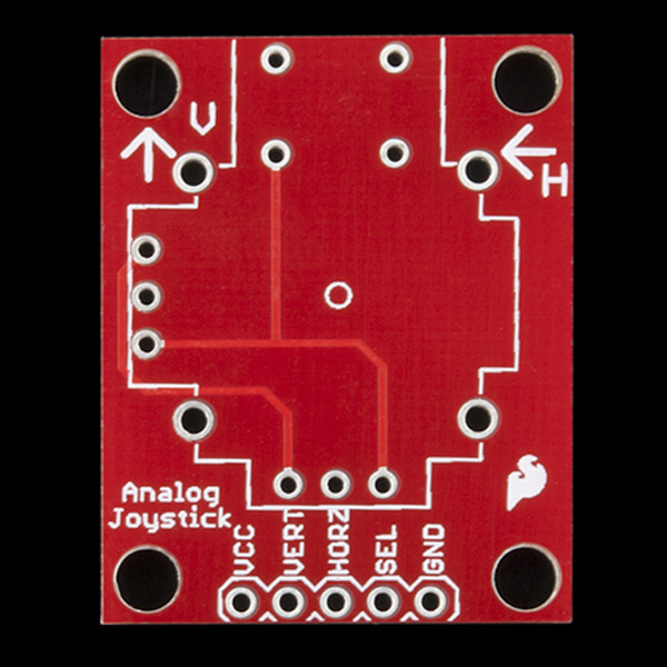
TFT LCD Breakout 1.8in 128x160 Hookup Guide

$
0
0

TFT LCD Breakout 1.8in 128x160 Hookup Guide a learn.sparkfun.com tutorial

Available online at: http://sfe.io/t854

Introduction

The TFT LCD Breakout 1.8in 128x160 is a versatile, colorful, and easy way to experiment with graphics or create a user interface for your project. In this guide we will familiarize ourselves with the hardware, explain how to connect the display to your microcontroller of choice, cover how to install the Arduino libraries, and give an overview of the software examples that you can start off with.

SparkFun TFT LCD Breakout - 1.8" (128x160)

SparkFun TFT LCD Breakout - 1.8" (128x160)

LCD-15143
$29.95

Required Materials

The TFT LCD Breakout has Plated-Through-Hole (PTH) connections. You can connect these in a number of different ways but we suggest soldering in breakaway headers for use with a breadboard. You'll also need an Arduino compatible microcontroller of your choice - we recommend something with extra RAM like the ESP32 Thing Plus or the RedBoard Turbo. You may not need everything on this wish list, depending on what you may already have. Add it to your cart, read through the guide, and adjust the cart as necessary.

Tools

In addition to those components, you'll need a soldering iron, solder, and probably some general soldering accessories to help with the job.

Solder Lead Free - 100-gram Spool

Solder Lead Free - 100-gram Spool

TOL-09325
$7.95
7
Weller WLC100 Soldering Station

Weller WLC100 Soldering Station

TOL-14228
$44.95

Suggested Reading

If you aren’t familiar with the following concepts, we recommend checking out these tutorials before continuing.

How to Solder: Through-Hole Soldering

This tutorial covers everything you need to know about through-hole soldering.

Installing an Arduino Library

How do I install a custom Arduino library? It's easy! This tutorial will go over how to install an Arduino library using the Arduino Library Manager. For libraries not linked with the Arduino IDE, we will also go over manually installing an Arduino library.

Serial Peripheral Interface (SPI)

SPI is commonly used to connect microcontrollers to peripherals such as sensors, shift registers, and SD cards.

Everything You Should Know About HyperDisplay

This is a tutorial to go in-depth about the SparkFun HyperDisplay Arduino Library.

Hardware Overview

TFT LCD Module (KWH018ST01)

The TFT module is the heart of this product -- it contains all the subsystems that are required to make an image show up. Starting with one of the most obvious features; the LCD screen is a glass panel with small little cells of liquid crystal (LC) material that can be shifted from opaque to clear with an electronic signal (more on how LCDs work). For each of the 128x160 pixels in the screen there are three LC cells and each cell has either a red, green, or blue filter in it to color the light. A pixel gets colored when white light from the LED backlight passes through the filtered cells in varying amounts.

LCDScreen

The amount of light passed through is controlled by the signal applied to the liquid crystal cells, but the sheer number of pins and complexity of those signals is totally impractical to control directly with a microcontroller. Fortunately some really smart cookies created a dedicated driver Integrated Circuit (IC) that stores pixel data and puts it on the screen for us. Connections to the driver, as well as the backlight, are broken out along a flexible flat printed circuit (FPC) cable - and that's where we take over.

FPC Connector

The FPC connector is convenient for two reasons. First, it's extremely simple to (re)connect the display to the breakout board. Second, production of this product is made easier because all soldering can be done in our normal surface mount process.

FPC Connector

To disconnect the TFT module just flip up the black locking bar with a finger or pair of tweezers and then gently pull the cable straight out from the connector. To put the cable back in, first make sure that the polarity indicators on the cable (1, 40) match up with those on the board and that the black locking bar is flipped up. Next push the cable in evenly for about 2mm.

Click on any of the below images for a closer look at what's going on:

Grasp Black Locking BarLift Black Locking Bar UpGently Pull TFT Connector Out

microSD Card Holder

The microSD card holder is there to relieve your microcontroller's poor memory due to having to store hundreds of images of cats, or really whatever you want to keep there. The SD card is connected to the same SPI bus as the display, which in turn keeps the required pin count low.

microSD card holder

Breakaway Panel

Out of the box, the TFT will come with a large backing PCB that makes it easy to securely mount the display in a project. If you need a more flexible solution you can remove the display module, snap off half the backing board, and then re-insert the display module. When this is done you'll be left with the bare minimum frame around the display to more seamlessly integrate with your project.

Breakaway point of the backing board

Breakaway Point of the Backing PCB

PCB Without the Backing Board

PCB Without the Backing Board

Pinout

The pinout of this breakout includes the standard SPI interfaces for both the TFT and the microSD card as well as a few specialty pins. You can power the breakout with either 5V or 3.3V thanks to the onboard voltage regulator and level shifter.

Pinouts
  • SDCS : The microSD card chip select, pull this pin low to talk to the microSD card
  • LCDCS : Chip select for the display, pull it low to talk to the TFT module
  • D/C : This is a special signal found in many display controllers. When it is high the incoming data is interpreted as data as opposed to commands when it is low.
  • TE : Tearing Effect is an optional output from the display to synchronize data writes - to avoid the 'Tearing Effect' that is seen when data is changed halfway through a screen refresh
  • MISO : On this line the microSD card sends data back to the uC
  • MOSI : The uC uses this line to send data into the TFT or microSD
  • SCLK : Provides synchronization, but rates of up to 32 MHz are possible
  • PWM : MOSFET input that allows a PWM signal to dim the backlight
  • 3V3-5V5 : Since the breakout has a voltage regulator and level shifter built in you can use it with either of these two popular voltages.
  • GND : It is important to stay grounded!

Hardware Hookup

So you've got this breakout board with a whole bunch of pins and all you want to do is make sure it works before you write a bunch of code, right? Let's talk about the bare minimum connections required to get things working.

Required for TFT Display
Breakout Pin Arduino Uno Esp32 Thing Plus Microcontroller Pin Requirements
MOSI1118/MOSIData output of chosen SPI port
SCLK135/SCKClock output of chosen SPI port
LCDCS514An output pin
D/C615An output pin
Required for microSD Card
Breakout Pin Arduino Uno Esp32 Thing Plus Microcontroller Pin Requirements
MOSI1118/MOSIData output of chosen SPI port
MISO1219/MISOData input of chosen SPI port
SCLK135/SCKClock output of chosen SPI port
SDCS427An output pin
Completely Optional
Breakout Pin Arduino Uno Esp32 Thing Plus Microcontroller Pin Requirements
PWM321An output pin, ideally PWM capable
TE717An input pin, ideally interrupt capable


Fritzing Diagram of Esp32 Thing Plus hooked up to SparkFun TFT 1.8" LCD Screen

Software Setup

Note: This example assumes you are using the latest version of the Arduino IDE on your desktop. If this is your first time using Arduino, please review our tutorial on installing the Arduino IDE. If you have not previously installed an Arduino library, please check out our installation guide.

Since the driver IC conveniently supports the SPI protocol you could start using it with just the stock Arduino libraries - but nobody wants to recreate the proverbial 'wheel' of computer graphics so we will get tricked out with the SparkFun HyperDisplay library and a driver made especially for this breakout.

Everything You Should Know About HyperDisplay

February 20, 2019

This is a tutorial to go in-depth about the SparkFun HyperDisplay Arduino Library.

HyperDisplay is an abstracted library for pretty much any 2D graphics display and has a focus on extensibility. Since the interface is standardized you can write display applications just once and make them work on many different displays with a few small changes. If you want to go more in depth check out this HyperDisplay tutorial. To get your TFT breakout working as soon as possible just keep reading along!

To use the breakout with HyperDisplay you will need to have all three of the following libraries installed in your Arduino IDE. You can head on over to the individual GitHub pages to download or simply click the appropriate link for each of the libraries listed below:

Library NameArduino Library Manager Search TermGitHub LinkDownload Link
HyperDisplaySparkFun HyperDisplayHyperDisplay GitHubHyperDisplay Download
HyperDisplay ILI9163CSparkFun HyperDisplay ILI9163CILI9163C GitHubILI9163C Download
HyperDisplay KWH018ST01 4WSPISparkFun HyperDisplay KWH018ST01 4WSPIKWH018ST01 4WSPI GitHubKWH018ST01 4WSPI Download

Check out this tutorial on how to install an Arduino library if you are unfamiliar.

Each of the libraries above contain some examples, however the ones that will actually make your TFT breakout light up are contained in the 'KWH018ST01' library -- in case you are wondering that name comes from the name of the TFT module that is used on the breakout. Once your libraries have been installed move on to the next section and try out a few of the examples.

Example Sketches

The HyperDisplay library for the TFT breakout is named after the LCD module that it uses - the KWH018ST01. If you've properly installed the required libraries, you'll notice a number of examples in File -> Examples -> SparkFun HyperDisplay KWH018ST01 4WSPI.

All of the following examples are explained in depth in the Everything You Should Know About HyperDisplay Tutorial. We'll show you a quick overview of each example here, but if you want more information on how these examples and their code work, head on over to the HyperDisplay Tutorial.

Everything You Should Know About HyperDisplay

February 20, 2019

This is a tutorial to go in-depth about the SparkFun HyperDisplay Arduino Library.

Examples 1-3

These are basic sketches to help you get the TFT running and show you the options for working with HyperDisplay.

Example 1

This first example just helps you determine if everything is hooked up correctly and you can upload code and images to your modules. To start, go to File->Examples->SparkFun HyperDisplay KWH018ST01 4WSPI Library and load Example1_DisplayTest. Make sure you have the correct board selected, as well as the correct COM port. In windows, it will look like this:

AdaFruit ESP32 Feather board Selected and COM54 selected

Click the image for a closer look.


Upload your code, and you should see the following:

Gif of Demo 3

Click the image for a closer look.

Does it work? If not, go back to the Hardware Hookup section and make sure all the connections are set correctly.

Example 2

This code walks you through the simplest uses of HyperDisplay so that you can start to write your own code. To start, go to File->Examples->SparkFun HyperDisplay KWH018ST01 4WSPI Library and load Example2_HyperDisplayBasics. As above, please make sure you have the correct board selected, as well as the correct COM port. Go ahead and upload your code.

Gif of Example 2

Click the image for a closer look.

Example 3

Example 3 goes over all the options currently available in the HyperDisplay drawing functions. To start, go to File->Examples->SparkFun HyperDisplay KWH018ST01 4WSPI Library and load Example3_AdvancedHyperDisplay. As above, please make sure you have the correct board selected, as well as the correct COM port. Go ahead and upload your code.

If everything is set up correctly, you should see the following. As noted above, text capabilities for the ESP32 Thing Plus are still a work in progress. Arduino boards will show some text, ESP32 Thing Plus boards will not.

Sped up GIF of Example 3

Click the image for a closer look.

Examples 4-6

These examples require a microcontroller with at least 6 kB RAM such as the Esp32 Thing Plus.

Example 4

This example shows you the basics of how to use the buffering abilities of HyperDisplay. To start, go to File->Examples->SparkFun HyperDisplay KWH018ST01 4WSPI Library and load Example4_BufferingHyperDisplay. As above, please make sure you have the correct board selected, as well as the correct COM port. Go ahead and upload your code.

You should see something like what we have pictured here:

Image of Example 4

Click the image for a closer look.

What you see may not be exactly what we have pictured here - some boards (like the ESP32 Thing Plus) have advanced memory protections in place and will not access uninitialized memory.

Example 5

This example highlights a unique use of a TFT display - visualizing the contents of RAM. Open Example5_ExploringRAM from the File->Examples->SparkFun HyperDisplay KWH018ST01 4WSPI Library folder and upload your code. You'll see something like the following:

Sped up GIF of example 5

Click the image for a closer look.

Example 9

Example9_Fractals uses Nick Gammon's Big Number Library to explore the Mandelbrot set fractal. It takes a few minutes to run through all the calculations, but the result is this beautiful image below:

Sped up GIF of Example 9 - Pretty Fractals!

Click the image for a closer look.

If you've followed along with the examples then you're well enough acquainted with the capabilities of your TFT breakout and the HyperDisplay library to venture out and start writing your own code. Fly, be free, and make something neat!

Resources and Going Further

For more information, check out some of the resources listed here:

Arduino Libraries:

Datasheets:

Need inspiration? Check out these other great display tutorials from SparkFun:

LED Light Bar Hookup

A quick overview of SparkFun's LED light bars, and some examples to show how to hook them up.

SparkFun Inventor's Kit for Photon Experiment Guide

Dive into the world of the Internet of Things with the SparkFun Inventor's Kit for Photon.

Large Digit Driver Hookup Guide

Getting started guide for the Large Digit display driver board. This tutorial explains how to solder the module (backpack) onto the back of the large 7-segment LED display and run example code from an Arduino.

Wireless Joystick Hookup Guide

A hookup guide for the SparkFun Wireless Joystick Kit.

Or check out some of these blog posts for ideas:


learn.sparkfun.com | CC BY-SA 3.0 | SparkFun Electronics | Niwot, Colorado
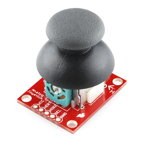
How to Use a Ruler

$
0
0

How to Use a Ruler a learn.sparkfun.com tutorial

Available online at: http://sfe.io/t885

Introduction

I know what you are asking? Why is there a guide for a ruler? It's a ruler, I've been using one of these since 3rd grade. That is true, but really I wanted a little extra room to talk about some of the features of the ruler, what they are, and why they are there. A while ago, we got some nice swag from our friends and Digi-Key, a PCB ruler with a lot of information on it. We realized a few things. First, PCBs make good rulers, they are sturdy while still being a bit bendable, and they are designed with precision. The precision of PCB traces is much more accurate than you would need in a ruler. Second I realized that usually when I need a ruler I'm not worried about the size of a SOIC package, there has to be information I would rather have on my ruler. So, I started playing in Eagle to design one with some of the information I tend to look up the most.

SparkFun PCB Ruler - 12 Inch

SparkFun PCB Ruler - 12 Inch

TOL-15295
$5.95

The Front

Let's start with the front. Nice and big you'll see the name, "One Ruler to Rule Them All". Other than the puns and geek reference, this is just designed to let you know this is the best ruler ever. Quite a few revisions went into this, as well as asking everyone I could find what they would like on a ruler.

SparkFun Ruler Front

Having a hard time seeing the ruler? Click the image for a closer look.

Metric

Let's go section by section starting on the left side. You'll see that this side is labeled "Metric", all the information on this side is in metric, starting with the actual ruler markings. The ruler is 12" long, that makes it 30.48cm long, so you'll see markings go just past the 30 mark.

Metric Side

Resistor, Ohm's, and Power Equations

Under the metric label, you'll see a few equations. Forget the equation for resistors in series or parallel (who doesn't)? Well, here you go. You'll also find Ohm's Law (V=RI) and the definition of Power (P=VI).

Reference Equations Ohm's Law, Power, Resistors in Parallel and Sreies

Label

On the bottom left you'll see a big white box. That's it, it is just a box. But this is a good place to write your name so people won't steal your ruler (or more likely will be reminded of whose ruler they stole). You can also use this to add any information you might want that isn't on the ruler (not likely since we put all known knowledge on this ruler).

Label

Keyboard Shortcuts

Next, you'll see the word Alt repeated over and over with numbers and weird markings. Well, that's because I never remember how to correctly type 330Ω resistor, and it can be easier to write out 3.1415926535897... than to remember how to type π. Hold down the alt key and type the number you see, and through magic forces, you can type an ∞ number of characters (see what I did there...).

KeyBoard Shortcuts

Light Spectrum

Next, we'll get to the color wavelengths. I've seen too many LED datasheets that just list a wavelength. Sometimes you are very particular about which shade of green. Sometimes you just want to know if the LED is green or red. This handy chart will let you know.

Part of the Light Spectrum

Protractor

Next is the fancy protractor. If you don't know what a protractor is I recommend finding the nearest 3rd grader and asking them. You could ask a math teacher, but you'd probably fall asleep after about 3 minutes (like you did in 3rd grade which is why you are asking what a protractor is). This is one change we had to keep making on various prototypes, the arc that is cut out is 2mm, anything smaller was too small to get a pen in, it may still be hard to get some pens in, but a pencil (especially a mechanical pencil) should work just fine. You'll also notice a small hole at the 90deg mark. This is also the exact center of the ruler which may or may not come in handy one day.

Protractor

Metric Prefixes

Next, we get to the main reason I made a ruler. I can never remember all the metric prefixes, so here they are in all their glory. From 10-15 to 1015 (in multiples of 3). So next time you are trying to remember which is smaller pico or nano remember your fancy ruler. Note: The ruler will not measure picometers or nanometers, it will just help you convert.

Metric Prefixes

Metric to Imperial Conversions

Next, we find the other reason for the ruler. Metric to Imperial conversions. While the rest of the world may not care how many feet are in a meter, those of us in the US (and don't forget Liberia and Myanmar) on occasion need to translate from stinky feet to what the rest of the world is talking about.

Metric to Imperial Conversions

PCB Trace Widths

On the very right, you'll see markings, to help you determine what a 0.1mm line looks like vs a 2.0mm line. This is actually one of those things that are useful when designing PCBs, knowing what the width of your traces actually looks like can be helpful. We've also added a mm to mil conversion.

PCB Trace Widths in Metric

Ohm's Law

Last but not least, is Ohm's Law again (this time reminding us all to fight back against the conformity of the Borg). Whew, that was a lot of stuff on a ruler, but wait, that's only the front...

Ohm's Law Spelled Out

The Back

On to the back side of the ruler.

Back of SparkFun Ruler

Having a hard time seeing the ruler? Click the image for a closer look.

Imperial

Starting on the left again, we see this side is labeled "Inches", you may also notice that the markings for the ruler are not uniform. The first 2 inches are divided into 1/2" and then 1/4", 1/8", 1/16", and 1/32" since sometimes these are important. The other 10 inches are divided by into 0.5", then 0.1" and finally 0.05".

Imperial Side

PCB Trace Widths

Under the inch designation you'll also see the definition of mil (1/1000 inch) and then more line width markings ranging from 0.005 to 0.1 inches (5mil to 100mil).

PCB Trace Width in Imperial

Morse Code

Next, you will see a Morse code cheat sheet. How often is it useful? Who knows, but next time someone starts banging out Morse code on your door in the middle of the night, you'll be thankful you have your ruler.

Morse Code

Digits of Pi

Near the bottom, you'll see π expanded out to more digits than you will need for any project and more than you will need to impress your family and friends with your knowledge of π (actually forget about memorizing π and learn to bake a pie, they'll be much more appreciative). If you are wondering how to type out the π symbol check out the front of the ruler.

Digits of Pi

Transistor and Diode Symbols

Next, are some transistor diagrams. It seems no one I talked to ever seemed to remember the configuration for transistors, so they are here as well.

Transistor Symbols

Just to the right of them, above the protractor, you'll find drawings of a few diodes as well.

Diode Symbols

Wire Gauge

Along the bottom, you'll find some wire gauges as well as their corresponding size (in mm). I did check these out on a few and the wire will fit in pretty snuggly in the correct hole. There is also a 1mm hole in the middle even though it doesn't correspond to any wire size.

Wire Gauge

Roman Numerals

Next is Roman Numerals. Why are they there? Honestly, I don't know, I figured I needed to put something there and it seemed reasonable. To be honest, the only time I've seen Roman Numerals used in the past 5 years, is for the Superbowl. But, if you ever find yourself back in ancient Rome and have a hard time reading the numbers, your ruler can help (although reading the numbers will probably be the least of your worries).

Roman Numerals

Fraction and Decimal Conversions

On the other hand, the Romans didn't have to deal with changing fractions to decimals. While you all probably know what 1/2 is, who remembers what 1/8 is or worse 5/16. Sometimes you need these numbers, so we've broken out a list of some of the more common value (and added a * for those that are repeating)

Fraction to Decimal Conversions

Machine Screw and Drill Sizes

Lastly, is the most confusing part of the ruler. Screw and drill sizes. This is mostly confusing, because of the complexity of the subject, you will find plenty of Tap and Drill Charts online, but this should be a decent summary of some of the more common sizes. With a given screw, the drill size you need will vary based on the material you are drilling into as well as the fit you want. The markings on the ruler give the major diameter of the screw (not the diameter of the hole), the screw name, and the drill bit required for 75% thread which is the size of the hole.

Machine Screw and Drill Sizes

That's about it, if you look you'll also find a few logos and a version number and such, but that is the basics of the SparkFun ruler. Get out draw some straight lines, measure things, and convert lots of things.

Resources and Going Further

For more information, check out the resources below:

Need some inspiration to use the ruler for your next project? Check out some of these tutorials:

How to Install and Setup EAGLE

Not just how to download and install EAGLE, but how to install the SparkFun EAGLE Libraries and scripts.

Using EAGLE: Board Layout

Part 2 of the Using Eagle tutorials, this one covers how to lay out a board after designing a schematic.

Importing Custom Images into Eagle

How to create custom graphics and import them into Eagle for silk, copper, etc.

Beginner's Guide to KiCad

An in-depth tutorial covering schematic capture, PCB layout, library editing, and gerber generation using this amazing open source PCB creation tool.

learn.sparkfun.com | CC BY-SA 3.0 | SparkFun Electronics | Niwot, Colorado
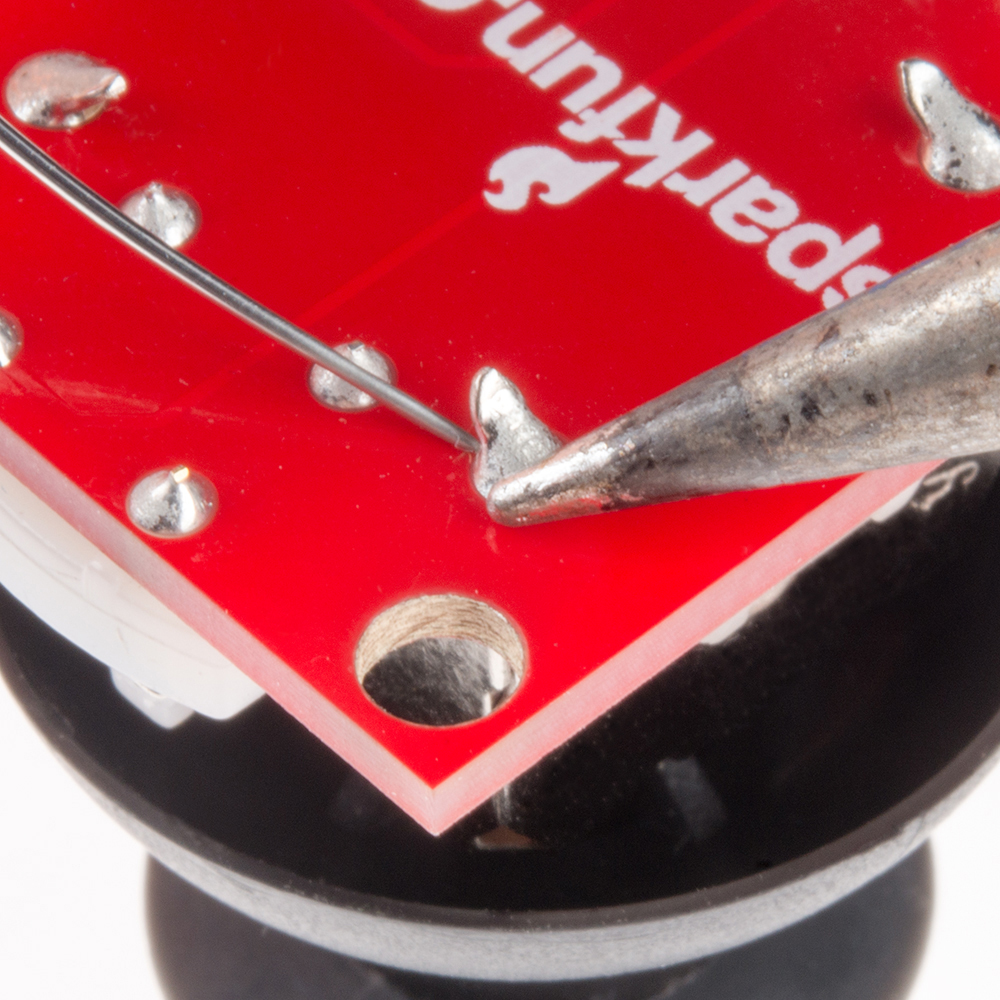
Qwiic Scale Hookup Guide

$
0
0

Qwiic Scale Hookup Guide a learn.sparkfun.com tutorial

Available online at: http://sfe.io/t880

Introduction

There are a variety of exciting projects around the measurement of the weight of an object. Whether it measuring if a chicken has left the coup, the bees have left at dawn, or automating the filling of liquids; being able to digitally interface to a scale is key. The Qwiic Scale is an incredibly easy way to read scales and their inner bits, load cells.

SparkFun Qwiic Scale - NAU7802

SparkFun Qwiic Scale - NAU7802

SEN-15242
$14.95

We’ve designed the Qwiic Scale so that little or no soldering is required. We’ve even written an Arduino library so that to get the weight of an object it’s as easy as:

language:c
float weight = myScale.getWeight(); 

Required Materials

If you’re just getting started we recommend obtaining a digital scale and hacking into it. This is because it can be tricky to correctly mechanically attach a load cell.

Bathroom scale with insides exposed

This low-cost scale already has the load cell properly mounted. Ready to be modified to an I2C addressable one.

Alternatively, if you have a unique application, or if this is not your first rodeo measuring weight, checkout the load cells we carry in a variety of shapes and capacities to create your own solution.

We're going to assume you’re just beginning with scales; we recommend you pick out a scale that has roughly the capacity of weight you want to measure. For example, a bathroom scale is best at measuring ~20lbs up to ~300lbs. If you’re trying to measure a few ounces then don’t use a bathroom scale, get a kitchen food scale instead.

Additionally, you’ll need an item of known weight. This will be used to calibrate your DIY scale. Depending on the accuracy needed for your project, you can use any object (can of soda 394 or 355.1g, dumbell, bag of flour, etc) as long as you know the weight or have an additional scale from which you can get a known weight.

Various items around the house with a known weight

10 pound plate, 4lbs flour, Diet coke, 100g calibration weight

Suggested Reading

If you’re unfamiliar with load cells, jumper pads, or I2C be sure to checkout some of these foundational tutorials.

Analog to Digital Conversion

The world is analog. Use analog to digital conversion to help digital devices interpret the world.

I2C

An introduction to I2C, one of the main embedded communications protocols in use today.

Getting Started with Load Cells

A tutorial defining what a load cell is and how to use one.

How to Work with Jumper Pads and PCB Traces

Handling PCB jumper pads and traces is an essential skill. Learn how to cut a PCB trace, add a solder jumper between pads to reroute connections, and repair a trace with the green wire method if a trace is damaged.

If you aren't familiar with the Qwiic system, we recommend reading here for an overview.

Qwiic Connect System

Hardware Overview

The Qwiic Scale is designed with the NAU7802 IC. This 24-bit analog-to-digital-converter is extremely precise and is designed to read the very small changes in voltage that a load cell or scale produce. SparkFun has carried a similar product, the HX711, for years. The NAU7802 shines in that it has all the great features of the HX711 but uses a true I2C interface allowing the Qwiic Scale to be daisy chained with other sensors and devices on the bus.

Qwiic Scale board

I2C Connections

As we mentioned earlier, two Qwiic connectors allow for easy daisy-chaining but if you prefer to wire in your own I2C connection the pins are available broken out at the edge of the board.

I2C pins and Qwiic connectors highlighted

Spring Terminal

A spring terminal is provided to make connecting to a scale possible without soldering. This terminal is operated by depressing the arm and inserting a wire. We found a ball-point pen or a small flat head screwdriver were handy to press one arm down at a time. The terminal can handle 20AWG to 26AWG size wire which is found on nearly all load cells.

Spring terminal highlighted

There are four silkscreen indicators next to the terminal showing which color wires should be inserted where. These are the ‘standard’ load cell wire colors but may vary slightly between manufacturers. If you’re in doubt, use your best guess and don’t worry - you can’t harm your load cell by wiring it backward!

Arm in the correct position

If the arm returns to level with terminal after inserting the wire then the spring is correctly pinching the wire. If the arm still looks pressed, slightly remove the wire until the terminal pinches on the wire, not the insulation.

PTH Pins

Additionally, we’ve broken out the ADC pins to PTH holes for advanced users. These are helpful if you have a more complex load cell that has a shielding around the wires (not required but helps reduce EMI).

Rear PTH pins for advanced users

Pin Definitions:

  • Red/E+ - Positive voltage of load cell energizing the wheatstone bridge. Most often connected to the red wire of a load cell.
  • Black/E- - Negative voltage of the load cell, most often connected to the black wire of a load cell.
  • White/A- - Negative branch of the wheatstone bridge, most often connected to the white wire of a load cell.
  • Green/A+ - Positive branch of the wheatstone bridge, most often connected to the green wire of a load cell.
  • B- - Called VIN2N in the datasheet. Optional 2nd ADC channel, negative input. This would connect to a 2nd load cell, sharing the E+/E- connections above.
  • B+ - Called VIN2P in the datasheet. Optional 2nd ADC channel, positive input. This would connect to a 2nd load cell, sharing the E+/E- connections above.

The NAU7802 is optimized to work with differential pairs meaning load cells and wheatstone bridge type devices. However, it is possible to hook up a regular analog signal between VIN1P with VIN1N connected to ground.

From the datasheet:

This device is optimized to accept differential input signals, but can also measure single-ended signals. When measuring single-ended signals with respect to ground, connect the negative input (VIN1N or VIN2N) to ground and connect the input signal to the positive input (VIN1P or VIN2P). Note that when this device is configured this way, only half of the converter full-scale range is used, since only positive digital output codes are produced.

Channel 2

The NAU7802 has a 2nd, optional ADC channel that has a much lower input capacitance (5pF vs 14pF) but is otherwise identical to the 1st channel. By default, this channel has a 330pF capacitor across its inputs. This helps reduce noise on channel one. If you’d like to use the 2nd channel, we recommend removing the capacitor by cutting the CAP jumper. Not sure how to cut a trace? Read here for more information!

2nd channel holes and CAP jumper

Interrupts / Data Ready

By default, the NAU7802 has an interrupt output pin that goes low when a conversion is complete and new data is available to be read. This interrupt can also be configured to go high when new data is available.

INT pin highlighted

For most applications the interrupt pin is not needed. New data is available at 10, 20, 40, 80, and 320Hz so we can poll the device at regular intervals rather than checking the interrupt pin but it's available for more advanced applications (such as extremely low power projects where the main controller is put to sleep between readings).

AVDD Pin

The NAU7802 has a built-in voltage regulator and will output 4.5V to 2.4V used to bias the load cell. By default, we set AVDD to 3.3V but lowering the bias voltage can be useful for power saving. The AVDD pin is available in case the user wishes to access this voltage as a reference; the AVDDshould not be used as a current source. Note that the regulator can only regulate down; you cannot power the board with 3.3V and ask the regulator to output 4.5V.

AVDD pins highlighted

I2C Jumper

Cutting the I2C jumper will remove the 2.2k&ohm; resistors from the I2C bus. In general, you shouldn’t need to mess with this jumper. But if you have many devices on your I2C bus, you may want to remove these resistors by cutting the two small traces between the solder pads. Not sure how to cut a jumper? Read here!

I2C jumper highlighted

Hardware Assembly

Below we disassemble a small kitchen scale with a common load cell to demonstrate how to attach the Qwiic Scale. Modifying a bathroom scale (for larger maximum weight) with four individual point load cells is possible but requires the routing of many more wires. We recommend a scale with a bar type load cell (most kitchen scales have this) for your first Qwiic Scale project.

A common 5kg max kitchen scale

A common 5kg max kitchen scale

Remove any sticker and cover to get access to two screws that secure the bar load cell to the floating platform.

Remove two screws to open the scale

This will release the platform from the base. Note the four wires connecting the load cell to the front area of electronics.

Open scale

This load cell has a blue wire instead of a green wire

Most load cells have four wires colored red, black, white, and green. If your load cell doesn’t, that’s ok! Checkout our troubleshooting section for how to suss out the correct connection.

Load cell with stranded wire

Are you hacking into a bathroom scale? These often use four individual cells that need to be combined into one complete load cell. We created the Load Cell Combinator to make this a lot easier. Once you have your combinator in place, you should have the four wires (Red, Black, White, Green) coming out of the combinator ready to connect to Qwiic Scale.

Bathroom scale with four cells shown connected to combinator board

If you are hacking into a kitchen scale or load cell with wires that are not stripped, use a pair of wire strippers to remove about ¼” of insulation.

Frayed stranded wire

Frayed stranded wire

Most load cells have stranded wire as opposed to solid core. Stranded wire helps reduce breaking wires when bent back and forth. The down side to stranded wire is that it tends to go everywhere when you try to insert it into a hole such as the spring terminal on Qwiic Scale. Before trying to insert the wire give the end a few twists with your fingers to get all the wires bent back together.

Twisted stranded wire

Twisted stranded wire

For extra points, after you’ve twisted the end of the wire hit it with a dab of molten solder - this will lock the wires into place. This is called 'tinning' and helps a lot when working with stranded wire but is not required.

Tinned twisted stranded wire

Twisted stranded wire tinned with solder

Now insert the first red wire into the spring terminal. If the arm returns to level with terminal, then the terminal is correctly pinching the wire. Give the wire a very light tug - it should hold in place.

Arm in the correct position

Arm in the correct position

If the arm is slightly depressed that means the wire has been inserted too deep and the terminal is pinching on the insulation around the wire. Press on the arm again and pull the wire slightly out until you hit the soft spot where the terminal pinches on wire, not the insulation.

Arm not in the correct position

Arm not in the correct position

Insert all four wires according to the color of wire and the silkscreen indicator on the Qwiic Scale PCB. Now attach Qwiic Scale to your RedBoard using a Qwiic cable or other microcontroller with a Qwiic Breadboard Cable. You're ready to start coding!

Four arms in correct position with four wires connected to RedBoard

Four arms in correct position with four wires connected to BlackBoard

Qwiic Scale Arduino Library and Overview

Note: This example assumes you are using the latest version of the Arduino IDE on your desktop. If this is your first time using Arduino, please review our tutorial on installing the Arduino IDE. If you have not previously installed an Arduino library, please check out our installation guide.

The SparkFun Qwiic Scale NAU7802 Arduino Library is a fully featured library for reading weights as well as configuring the IC. We recommend you install the library via the Arduino IDE by using the library manager and search for SparkFun Scale. Or you can download and manually installing a zip of the library by clicking on the link below. For those who want to view the code, check out the GitHub repo.

Once you have the library installed we recommend you start with Example1 and advance through the examples as you go. You do not need to read or absorb all the following functions, they are demonstrated and described in the examples. But if you're really advanced and just want the available functions, here they are:

  • bool begin(TwoWire &wirePort = Wire) - Check communication and initialize sensor. Returns true if sensor is successfully started. Optionally, you can pass in a different Wire port.
  • bool isConnected() - Returns true if device acknowledges a call to its I2C address.
  • bool available() - Returns true if Cycle Ready bit is set (conversion is complete).
  • uint32_t getReading() - Returns 24-bit reading. Assumes CR Cycle Ready bit (ADC conversion complete) has been checked by .available().
  • uint32_t getAverage(uint8_t samplesToTake) - Return the average of a given number of readings.
  • void calculateZeroOffset(uint8_t averageAmount = 8) - Also called taring. Call this with nothing on the scale.
  • void setZeroOffset(uint32_t newZeroOffset) - Sets the internal variable. Useful for users who are loading values from NVM.
  • uint32_t getZeroOffset() - Ask library for the zero offset value. Useful for storing value into NVM.
  • void calculateCalibrationFactor(float weightOnScale, uint8_t averageAmount = 8) - Call this with the value of the thing on the scale. Sets the calibration factor based on the weight on scale and zero offset.
  • void setCalibrationFactor(float calFactor) - Pass a known calibration factor into library. Helpful when loading settings from NVM.
  • float getCalibrationFactor() - Ask library for the calibration factor. Useful for storing value into NVM.
  • float getWeight(bool allowNegativeWeights = false) - Once you've set zero offset and cal factor, you can ask the library to do the calculations for you. By default, negative weights will be returned as 0.
  • bool setGain(uint8_t gainValue) - Set the gain by calling myScale.setGain(NAU7802_GAIN_16). x1, 2, 4, 8, 16, 32, 64, 128 are available.
  • bool setLDO(uint8_t ldoValue) - Set the onboard Low-Drop-Out voltage regulator to a given value by calling myScale.setLDO(NAU7802_LDO_3V6). 2.4, 2.7, 3.0, 3.3, 3.6, 3.9, 4.2, 4.5V are available.
  • bool setSampleRate(uint8_t rate) - Set the readings per second by calling myScale.setSampleRate(NAU7802_SPS_80). 10, 20, 40, 80, and 320 samples per second is available.
  • bool setChannel(uint8_t channelNumber) - Select between 1 and 2
  • bool calibrateAFE() - Calibrate the analog front end of the IC. This function is unrelated to setting the zero offset and calibration factor and should rarely be used. It is recommended that the AFE be re-calibrated any time the gain, SPS, or channel number is changed. Returns true if CAL_ERR bit is 0 (no error).
  • bool reset() - Resets all registers to Power On Defaults
  • bool powerUp() - Power up digital and analog sections of scale, ~2mA
  • bool powerDown() - Puts scale into low-power 200nA mode
  • bool setIntPolarityHigh() - Set Int pin to be high when data is ready (default)
  • bool setIntPolarityLow() - Set Int pin to be low when data is ready
  • uint8_t getRevisionCode() - Get the revision code of this IC. Always 0x0F.

Here are the lower level functions to manipulate registers:

  • bool setBit(uint8_t bitNumber, uint8_t registerAddress) - Mask & set a given bit within a register
  • bool clearBit(uint8_t bitNumber, uint8_t registerAddress) - Mask & clear a given bit within a register
  • bool getBit(uint8_t bitNumber, uint8_t registerAddress) - Return a given bit within a register
  • uint8_t getRegister(uint8_t registerAddress) - Get contents of a register
  • bool setRegister(uint8_t registerAddress, uint8_t value) - Send a given value to be written to given address. Return true if successful.

Examples

The following examples highlighted from the library will show the readings on a serial monitor.

Example 1: Basic Readings

Example 1 will show you basic output from the NAU7802. This is helpful for getting the basic hardware setup. If you've got everything wired up correctly than the value should change by thousands or hundreds of thousands as you press on your scale.

Output ADC values to serial port

Example 2: Complete Scale

Example 2 is where it starts to get interesting. This example will show you how to characterize your scale. You’ll need a scale fully setup and a known weight (like a dumbbell or can of soda).

Displaying weight in terminal window

Advanced Examples

We included additional examples in the library demonstrating how to change the gain, sample rate, as well as how to shut the IC down for low-power projects. For platforms that have multiple Wire ports (i.e. Teensy, not Uno), we also offer an AdvancedI2C example showing how to point the library to use Wire1.

How to Characterize Your Scale

You should have your scale hooked up, but there's one more step before we get measuring. It's time to teach your scale how much one thing weighs so it can tell how much everything else weighs!

Load cells have a linear response meaning their value changes in proportion to the force or weight applied to it. Remember the y = mx + b stuff you learned in school? It’s ok if you didn’t! The characterization of a scale looks like this:

  • Hookup the scale and get the Example1_BasicReadings.ino outputting a good, changing value.
  • Load Example2_CompleteScale.ino
  • Take everything off your scale and press ‘c’ to get a ‘zero’ reading
  • Place a known weight (can of soda, weight lifting plate, etc) on your scale and enter its value. For example, if you placed a 150 gram weight on your scale, enter 150.0.

That’s it. You can remove the known weight and weigh anything else you have lying around. But what’s really going on?

A graph showing the relationship between weight and the load cell reading

Instead of y = mx + b imagine weight = calibrationFactor * reading + zeroOffset.

The SparkFun library for the NAU7802 takes digital readings. These readings will vary from 10,000 to over 1 million. These values are unitless - the IC doesn’t know if there’s grams or lbs or stones on your scale, all it knows is the change in value. So when you remove all weight from your scale, there’s still a non-zero value being measured. We call this the zero offset (also known as the +b portion of the y = mx + b) and it’s set when you call the calculateZeroOffset() function. When you place a known weight on the scale and call the calculateCalibrationFactor(150.0) function the library will do the following math (and set the m portion of y=mx+b).

Let's say you measured 213417 with nothing on the scale. Once you added 150grams the scale measured 265412. From these numbers we can calculate the slope of the line:

language:latex
Zero offset = 213417
Calibration factor = (265412 - 213417) / 150 = 346.6333

We now know that for every change of 346 in the digital reading we are seeing a change of 1 gram. NEAT.

Now, whatever we put on the scale we can get its weight by extrapolating between the zero offset and the known weight. For example, if we put an unknown thing on the scale and get a reading of 244094 we know:

language:latex
244094 - 213417 = 30677

30677 / 346.633 = 88.4999

88.5 grams! Again, these values are unitless but as long as you know that the known weight was in grams, then the ‘weight’ is output in grams.

FAQ and Troubleshooting

The Full Scale Example Never Changes from Zero.

Are you seeing something like this? Where the readings are changing but the weight doesn't?

Reading changing but weight is not

If you see the readings are decreasing when you press on the scale, then the A+/A- wires are probably backwards. Because the readings go down with more weight, the displayed weight will never go above zero. Try reversing the white and green wires.

The Values Decreasing When I Push Down on the Load Cell! Help!

A+/A- wires are probably backwards. Try reversing the white and green wires.

Example1 Displays Constant Values ~1000 / ~8,000,000 / ~ 16,000,000 / The Scale Doesn’t Work

More than likely you have a wire that is not making contact. Be sure to insert the stripped wire into the spring terminal but not too far. If the terminal is ‘pinching’ on the insulation rather than the wire then it will not make an electrical connection. Press down on the arm and pull the wire out a few millimeters.

Can I Measure 0.001 Grams?

Probably not. Really high precision scales don't use load cells for a variety of reasons. Check out 'weight scale elements' which are basically a balance scale that uses an electromagnet and a PID loop.

We were able to reliably and accurately measure a change of 5 grams on a 10kg max load cell, or 0.05%. So on a 200kg load cell that’s 100 grams. On a smaller 100g max load cell you may be able to reliably measure down to 50 milligrams.

Here are some things to consider as you get into finer accuracy measurements:

  • Temperature variations in the load cell will change the zero offset and known weight values. You’ll need to recharacterize your scale if the temperature swings more than a couple degrees Celsius.
  • For milli and micro gram readings, professional scales will often have a air cover reducing the effects of small currents in the environment.
  • Vibrations from HVAC equipment, trains, etc can affect readings.

The Wire Colors on My Load Cell Don’t Match Anything Here!

Never fear. Disconnect the wires from Qwiic Scale and use a multimeter to measure the resistance between each wire. Take notes as you go. Start with one wire and find the lowest resistance to two others. You now know this wire falls in between the other two in the wheatstone bridge shown below.

Image of a wheatstone bridge

Once you have the pairs of wires identified (possible VCC/GND pair and A+/A- pair) then attach those pairs to Qwiic Scale. If the readings go down when you press on the scale, then you’ve got A+/A- reversed. If the scale doesn’t work at all then swap the pairs so that your assumed VCC/GND move into A+/A- and vice versa.

My 1000kg Load Cell is Acting Oddly.

By default, the library sets the gain to the maximum of 128 because most of our users are measuring smaller load cells. If you’re measuring very large weights, you may need to reduce the gain by using the following command:

language:c
myScale.setGain(NAU7802_GAIN_16);

Gains of 1, 2, 4, 8, 16, 32, 64, and 128 are available.

How Much Does a Can of Soda Weigh?

I’m glad you asked because it’s fascinating that it changes between regular (394g) and diet (355.1g). Read all about it from the Virtual Chembook:

Resources and Going Further

We hope you’ve enjoyed learning about Qwiic Scale and Load Cells in general. For more information, check out the resources below:

Be sure to checkout the hookup guides for other Qwiic devices to see how easy it is to measure and control the world!

I2C

An introduction to I2C, one of the main embedded communications protocols in use today.

Qwiic IR Array (MLX90640) Hookup Guide

The Melexis MLX90640 contains a 32x24 array of thermopile sensors creating, in essence, a low resolution thermal imaging camera. In this guide, we’ll go over how to connect your Qwiic Infrared Array with MLX90640 and get it communicating with Processing to produce a nice thermal image.

Qwiic Proximity Sensor (VCNL4040) Hookup Guide

The SparkFun Qwiic Proximity Sensor is a great, qualitative proximity (up to 20 cm) and light sensor. This hookup guide covers a few examples to retrieve basic sensor readings.
New!

Build a Qwiic Jukebox that is Toddler Approved!

Follow this tutorial to build your own custom jukebox. Note, this is designed simple and tough for use primarily with toddlers. It's also a great introduction to SparkFun's Qwiic products!

learn.sparkfun.com | CC BY-SA 3.0 | SparkFun Electronics | Niwot, Colorado
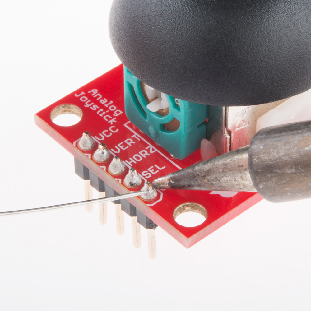
How to Create a MakeCode Package for Micro:Bit

$
0
0

How to Create a MakeCode Package for Micro:Bit a learn.sparkfun.com tutorial

Available online at: http://sfe.io/t896

Introduction

Microsoft MakeCode is a block based coding language designed to introduce people to coding. MakeCode is nice because it allows the basic structures and thought processes used in algorithm design to take place without having to worry about syntax or data type. Under the hood, MakeCode is based on static typescript and javascript. In this tutorial, we'll develop a MakeCode extension for the Soil Moisture Sensor using an existing SparkFun extension.

Thing's You'll Need

First, let's set up our build environment, we'll start by downloading and installing node.js. You'll also need a Github account. Now go ahead and open any old command prompt and navigate to to where you store your Github files (I create a Github folder on my C drive so for me this is C:\Github). Then go ahead and run the following commands

npm install
npm install jake
npm install typings

This installs a few npm packages to use, We'll then clone the PXT directory into our Github folder and run these npm packages we just installed. At the end, back out to the Github folder once more. This is accomplished with the following commands.

git clone https://github.com/microsoft/pxt
cd pxt
git checkout v0
npm install
typings install
jake
cd..

We'll then clone in the Micro:Bit target, and install pxt there.

git clone https://github.com/Microsoft/pxt-microbit
cd pxt-microbit
npm install -g pxt
npm install
cd..

This should be everything we need to build our project, now let's clone in the existing SparkFun MakeCode package and get started editing it.

git clone https://github.com/sparkfun/pxt-gator-light

What to Change

Let's go ahead and create a new Github repository for our new MakeCode package, we'll call it pxt-gator-moisture. Clone this repo into your Github folder, then go ahead and copy over the contents of the pxt-gator-light repo. We'll mainly be looking at the two gatorlight files, the pxt.JSON file, the ReadMe, and eventually, the icon.jpg

pxt-gator-moisture

We must change these files

First, we're going to go through and rename everything to gatormoisture, so go ahead and rename the two gatorlight files, once we've renamed them, go ahead and open up pxt.json and replace every instance of the word light with moisture. The .json file tells MakeCode which files to include, and since we changed our filenames, we'll have to change them here as well. Don't neglect to roll the version number back to 0.0.1 as well as change the description to something that makes more sense. We're then going to open up both gatormoisture files and replace every instance of light with moisture once again.

Let's now look at where the code behind our blocks actually lives, the blocks live in the .ts file while the actual functions live in the .cpp. Let's check out the .cpp first. We make sure to include pxt.h with every package, as well as use the pxt namespace. We then create a namespace, "gatormoisture" and put the function that calculates lux from a given ADC value. It's a pretty simple function but we'll be able to call it from our .ts file, which is what we really wanted

language:c
#include "pxt.h"
#include <cstdint>
#include <math.h>

using namespace pxt;

namespace gatorMoisture {
    /*
    * Calculates the light in Lux based on the ADC value passed in. 1 step in adcVal is equal to .488 uA or .976 lux at 5V
    */
    //%
    uint16_t getLux(int16_t ADCVal) {
        return ADCVal * .976;
    }

}

While we're here, let's change getLux to a getMoisture function that returns a float in between 0 and 1 instead of a value in lux. For this, we will simply divide the ADCVal passed in by the full-scale range of the ADC (1023). In the end, our gatormoisture.cpp looks like the following.

language:c
#include "pxt.h"
#include <cstdint>
#include <math.h>

using namespace pxt;

namespace gatorMoisture {
    /*
    * Calculates the light in Lux based on the ADC value passed in. 1 step in adcVal is equal to .488 uA or .976 lux at 5V
    */
    //%
    float getMoisture(int16_t ADCVal) {
        return ADCVal / 1023.0;
    }
}

Now let's check out how our blocks are created in the .ts file, which should look like the following after we've changed everything from light to moisture.

enum gatorMoistureType{
    moisture=1,
    adcVal=2,
}

//% color=#f44242 icon="\uf185"
namespace gatorMoisture {

    // Functions for reading moisture from the gatormoisture in moisture or straight adv value

    /**
    * Reads the number
    */
    //% weight=30 blockId="gatorMoisture_moisture" block="Get moisture on pin %pin | in %gatorMoistureType"
    export function moisture(pin: AnalogPin, type: gatorMoistureType): number{
        let ADCVal = pins.analogReadPin(pin)
        switch(type){
            case gatorMoistureType.moisture: return getMoisture(ADCVal)
            case gatorMoistureType.adcVal: return ADCVal
            default: return -11111111
        }
    }

    /**
     * Function used for simulator, actual implementation is in gatormoisture.cpp
     */
    //% shim=gatorMoisture::getMoisture
    function getMoisture(ADCVal: number) {
        // Fake function for simulator
        return 0
    }
}

If we want to have options in dropdowns for our blocks, we create them using an enum. We will be able to choose whether we want moisture, a value between 0 and 1, or the straight adcVal, so outside of the namespace, we create an enum (shown below) for our possible data types.

enum gatorMoistureType{
    moisture=1,
    adcVal=2,
}

We then must pick a color and icon for our extension, which is done in the line before we declare our namespace. The color can be any 6-digit, hexadecimal value, while the icon will use it's identifier from the FontAwesome icon library. The color and icon declarations are shown below.

language:c
//% color=#f44242 icon="\uf185"

We then need to define what our block looks like and where it sits relative to other blocks. This is done by setting weight, blockId, and block. A block with weight 100 will list itself above blocks with weights below 100 and and below blocks with weights above 100. This allows you to decide how you want all of your blocks to be listed. The blockId MUST be mynamespacetitle_functionTitle so for our moisture block, which is in the gatorMoisture namespace, our blockId will be gatorMoisture_moisture. Finally, we decide exactly what goes into the text for the block using the block string. Any variable that we want to become a dropdown will be prefaced with a %. The following code will create a block with a dropdown for pin selection and a dropdown that allows you to choose between moisture and adcVal. This block will call the function moisture using whatever arguments that have been selected from the dropdown.

//% weight=30 blockId="gatorMoisture_moisture" block="Get moisture on pin %pin | in %gatorMoistureType"

Finally, we'll need to write the function that actually reads our pin. Any function that is declared as export will appear as a block in MakeCode. Arguments for this function will be whatever we declared as dropdown capable variables and we'll usually need to set up a switch statement based on the type to return the proper values for each type selected. Notice how we call getMoisture, the function contained in our .cpp when our type is moisture. We also must declare what the function returns, in this case, a number.

export function moisture(pin: AnalogPin, type: gatorMoistureType): number{
    let ADCVal = pins.analogReadPin(pin)
    switch(type){
        case gatorMoistureType.moisture: return getMoisture(ADCVal)
        case gatorMoistureType.adcVal: return ADCVal
        default: return -11111111
    }
}

Any functions in our .cpp will need a dummy function for the simulator. We create the analog for our getMoisture function as follows. Notice how, since it isn't exported, we won't see it in MakeCode.

//% shim=gatorMoisture::getMoisture
function getMoisture(ADCVal: number) {
    // Fake function for simulator
    return 0
}

Finally we'll need to change the final part of the README (line 49) to our namespace followed by the github address, this looks like gatorMoisture=github:sparkfun/pxt-gator-soil and allows the package to be recognized as a MakeCode extension

Compiling your Code

Now that we've written all of our code, it's time to compile and test it, go ahead and open up a command prompt window and navigate to the directory where your MakeCode package lives. Once there, run the following commands to link to PXT and build your code.

npm install
npm install typings
npm install jake
npm link ../pxt
pxt target microbit
pxt install
pxt build

We then want to commit and push our changes to Github.

git add -A
git commit -m "changing names to gator:moisture"
git push

If we know all of our code works and has been tested, and we want to release a new version, run the pxt bump command. You will then be prompted to enter a version number with which to tag your release, just make sure it's higher than or equal to the version that you are being prompted to enter. The command will then tag your commit and push it to Github as a release.

PXT Bump

PXT Bump

Test, Rinse, Repeat!

To test our code, let's go ahead and open up the MakeCode Website and navigate down to extensions.

Extensions

Extensions

From there, we'll log into our Github using a token, to do this, simply follow the instructions when you click login to Github.

Login to Github

Login to Github

After we log in, we can paste the URL for the Github repo into the extension search bar, click on the result to include it! If it doesn't pop up, ensure that your repository is public.

Once you've included your extension, feel free to check out its various features, edit the code as necessary and re-upload it to Github until you're satisfied!

Going Further

In the end we'll eventually want our extension to be approved by Microsoft. To do this, fill out this form to get started getting your package approved.


learn.sparkfun.com | CC BY-SA 3.0 | SparkFun Electronics | Niwot, Colorado

Viewing all 1123 articles
Browse latest View live


<script src="https://jsc.adskeeper.com/r/s/rssing.com.1596347.js" async> </script>