Using Home Assistant to Expand Your Home Automations a learn.sparkfun.com tutorial
Introduction
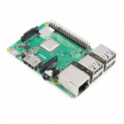
In this tutorial, you'll learn everything you need to know to get started controlling your home with Home Assistant, an open source home automation hub that puts local control and privacy first, running off of a Raspberry Pi. In this tutorial we'll cover how to set up Home Assistant, and regardless of whether you created the devices yourself or purchased off the shelf IoT devices, get them working together in harmony.
While this guide walks you through the setup of Home Assistant, this is not a tutorial about how to get the most out of Home Assistant (but a quick Google search for Home Assistant tutorials will provide you with endless links to do so).
Image courtesy of home-assistant.io
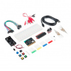
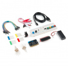
Required Materials
To follow along with the examples in this tutorial, you will need the following pieces of hardware. You may not need everything though depending on what you have. Add it to your cart, read through the guide, and adjust the cart as necessary.
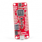
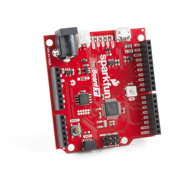
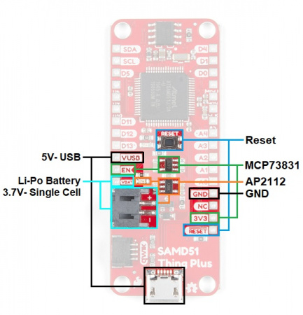
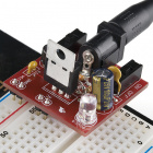
⚡WARNING!If you plan to power your ESP32 Thing Plus via a wallwart, make sure your power supply is
5V, NOT 5.1V. We have noticed a power spike in our
5.1V power supplies, that can damage the IC. Long cables can also generate a large enough voltage spike to damage the IC. We recommend keeping power supply cables shorter than 6 feet to minimize potential damage.
Optional Materials
Depending on your setup, you may also need the following.
In stock
COM-13833
This is a class 10 16GB microSD memory card, perfect for housing operating systems for single board computers and a multitude…
5In stock
LCD-13733
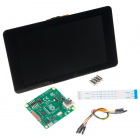
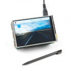
This 7" Raspberry Pi Touchscreen LCD provides you with the ability to create a standalone device that can be utilized as a cu…
39In stock
LCD-14776
This LCD Touchscreen HAT fits on top of the Raspberry Pi, practically form fitting on top of it so as not to compromise the o…
1In stock
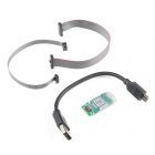
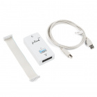
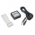
WIG-14271
With Single-Board Computers (SBCs) on the rise, it is a good idea to have an easy way to interface with them. Operating on a …
3Suggested Reading
If you aren't familiar with the following concepts, we recommend checking out these tutorials before continuing.
Introduction to MQTT
An introduction to MQTT, one of the main communication protocols used with the Internet of Things (IoT).
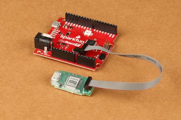
Installing Home Assistant
To get started, we'll first need to install Home Assistant by downloading the image for your device. Home Assistant's installation page does a great job outlining how to flash the image to your SD card, but after you download your image you'll need to install Hass.io by connecting your SD card to your computer and flash the image using a program called balenaEtcher.
Providing an Internet Connection
Next we need to make sure your Pi will have an Internet connection. To get up and running fast and reliably we'll be using a hardwired connection to our router. But if you'd prefer WiFi, you can either use a blank USB stick with a Fat32 partition (with the partition labeled "CONFIG"), and while in the root (/) directory, create a network/my-network file. Or on the Hassio SD card first bootable partition, create CONFIG/network/my-network file. For the structure of the network file, follow the HassOS howto.
Once the network has been setup, insert the SD card and USB stick, if used, into the Pi. Connect power to the Pi, and wait for the OS to boot. For this first boot, Home Assistant will download the latest version, which will take ~20 minutes.
After the very long first boot, you will be able to reach your device from a browser at http://hassio.local:8123 (assuming your router supports mDNS). If your router doesn't support mDNS, or you're unsure, you'll need to use the IP address of your Pi instead (e.g. 192.168.1.108:8123). You can find the IP address by logging into your router (typically by typing 192.168.1.1 into the address bar of your browser), finding your Pi (should be named hassio).
Click the image for a closer look.
Logging in to Home Assistant
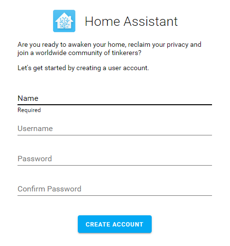
Once Home Assistant has finished updating and you're able to connect to the Pi, you should be greeted with a login screen to create a user name and password to log into Home Assistant. Make sure to keep track of the login used. we'll need those credentials later when we set up our ESP devices.
Once logged in, you'll be welcomed by the home screen. Home Assistant will automatically scan your network to add devices. You may receive a few notifications to set up the devices found, typically these are home media devices, such as Google cast, Plex, etc.
Click the image for a closer look.
Configuring Home Asssistant
Now that we have Home Assistant set up, we need to configure it. One of the benefits of Home Assistant is it's open source, allowing people from the community to create their own add-ons on top of the officially supported add-ons, which can make customizing it a lot faster and easier than other options. In this section we'll need to enable two extensions: Configurator and MQTT.
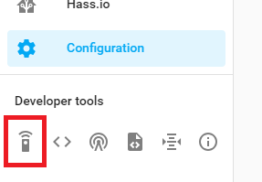
To view the available add-ons, click on the Hass.io tab on the left side menu, followed by clicking on the ADD-ON STORE tab along the top as shown below (similarly, you can go to http://hassio.local:8123/hassio/store).
Click the image for a closer look.
Adding the Configurator Add-On
Regardless of what you ultimately use Home Assistant for, one add-on that will make configuring Home Assistant easy without having to SSH into your Pi is the Configurator under Official add-ons. The Configurator allows you to browse and modify the files on your Pi. Later on we'll be using this add-on to modify the configuration.yaml and automations.yaml files.
To add the Configurator, click on the Configurator add-on, and click install. After the add-on has been installed, you'll want to click start and enable the "Show in Sidebar" option, and that will add a new option to your left menu bar with the name "Configurator" after you reload the page.
Click the image for a closer look.
We'll need to use this add-on later after we get more of our hardware setup.
Adding the Mosquitto Broker
Mosquitto is an open source MQTT broker server that receives and distribute messages over the MQTT server. For more information about MQTT, check out the MQTT tutorial. We'll setup the Mosquitto broker the same way we did the Configurator. First click on the Mosquitto broker under the offical add-ons section of the add-on store. Click install, and wait for Home Assistant to download and add Mosquitto. After it's finished downloading, click start to enable the MQTT broker.
Click the image for a closer look.
Using the Configurator to well... configure
Before we can start using MQTT, we need to configure Home Assistant's MQTT broker. First click on "Configurator" from the left menu bar.
Click the image for a closer look.
We enabled MQTT from the add-on store, but now we need to configure it. All of your configurations are stored in the appropriately named file called configuration.yaml. YAML files are a human-readable data serialization language, similar to header files in C++, which are commonly used for configuration files. Similar to python, YAML files use indentations to indicate nesting, so be careful with your indents when you modify a YAML file.
To open the configurations file, first click on the folder icon to browse the file system.
Click the image for a closer look.
Navigate to the configuration file located at /config/configuration.yaml
Click the image for a closer look.
This configuration page is where we'll initialize our MQTT broker and devices. The first thing we'll initialize is the broker. Copy the following lines into the configuration file. It doesn't matter where these lines go in the file, but we'll place it just below the discovery. Make sure to replace the IP address with the IP of your Pi.
mqtt:
    broker: 192.168.1.- # This is the IP address of the Pi, which can be found from your client list of your router
Once that's done we can save changes by pressing save icon.
Click the image for a closer look.
Every time we make a change to any of the files, we'll want to first check that the configuration is valid, and then restart Home Assistant. To check the configuration, go to the tab labeled Configuration NOT Configurator along the left side, and select General, and click "CHECK CONFIG". If the syntax is correct, it will display a message "Configuration Valid". If not it will show you a debug message showing where the error occurred that needs to be fixed. Once the configuration is valid, press "RESTART" under Server Management, and wait a minute for the changes to be applied.
Click the image for a closer look.
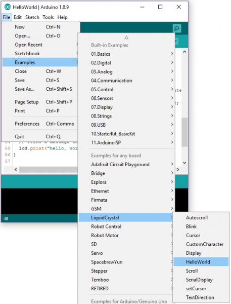
Example 1: MQTT + ESP32
Note: This Arduino code used in this example has been written and tested on Arduino IDE version 1.8.6. Otherwise, make sure you are using the latest stable version of the Arduino IDE on your desktop. If this is your first time using Arduino, please review our tutorial on
installing the Arduino IDE. If you have not previously installed an Arduino library, please check out our
installation guide. Now that we have the MQTT server running, it's time to add some devices. For this first example we'll connect two ESP32 Thing Plus boards to our network over MQTT. If you're unsure of what MQTT is and how it works, there's a guide for that! Check out the MQTT tutorial below:
Introduction to MQTT
An introduction to MQTT, one of the main communication protocols used with the Internet of Things (IoT).
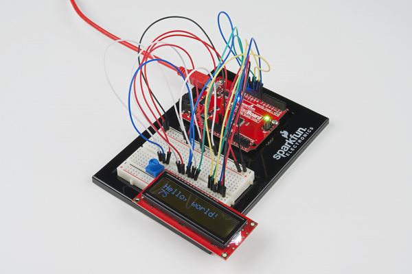
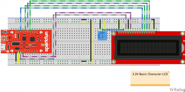
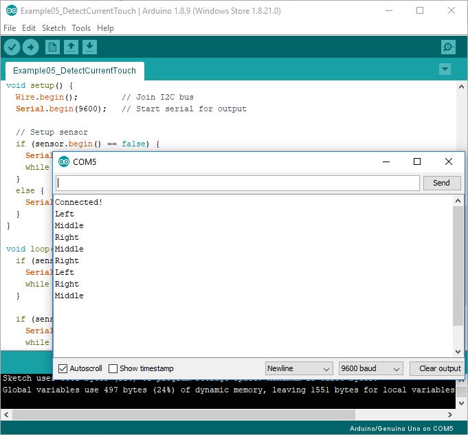
The first device we'll add will be a switch that waits for the button connected to IO pin 0 to be pressed. Once pressed the button will publish to the topic room/light with message of "on" or "off". The second ESP32 will subscribe to the same topic room/light and listen for messages from the switch. When the message "on" is received, it will turn on the LED connected to IO pin 13, and when "off" is received, turn the LED off. To do this we'll need to flash the ESP32 Thing Plus boards with some code using Arduino.
MQTT Switch
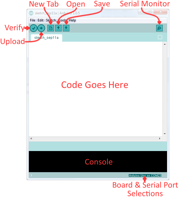
Copy and paste the code below into your Arduino IDE, make sure to select ESP32 Dev Module as your board, and the correct COM port is selected. Fill in the information for your WiFi credentials (your WiFi network must be on the same network as the Raspberry Pi), your user name and password you created for Home Assistant, and the IP address of the Pi.
language:c
/******************************************************************************
MQTT_Switch_Example.ino
Example for controlling a light using an MQTT switch
by: Alex Wende, SparkFun Electronics

This sketch connects the ESP32 to a MQTT broker and subcribes to the topic
room/light. When the button is pressed, the client will toggle between
publishing "on" and "off".
******************************************************************************/

#include <WiFi.h>
#include <PubSubClient.h>

// WiFi Network Credentials
const char *ssid =  "-----";   // name of your WiFi network
const char *password =  "-----"; // password of the WiFi network

// Home Assistant Credentials
const char *HA_USER = "-----";
const char *HA_PASS = "-----";

// MQTT Network
IPAddress broker(192,168,1,-); // IP address of your MQTT broker eg. 192.168.1.50
const byte SWITCH_PIN = 0;           // Pin to control the light with
const char *ID = "Example_Switch";  // Name of our device, must be unique
const char *TOPIC = "room/light";  // Topic to subcribe to
WiFiClient wclient;

PubSubClient client(wclient); // Setup MQTT client
bool state=0;

// Connect to WiFi network
void setup_wifi() {
  Serial.print("\nConnecting to ");
  Serial.println(ssid);

  WiFi.begin(ssid, password); // Connect to network

  while (WiFi.status() != WL_CONNECTED) { // Wait for connection
    delay(500);
    Serial.print(".");
  }

  Serial.println();
  Serial.println("WiFi connected");
  Serial.print("IP address: ");
  Serial.println(WiFi.localIP());
}

// Reconnect to client
void reconnect() {
  // Loop until we're reconnected
  while (!client.connected()) {
    Serial.print("Attempting MQTT connection...");
    // Attempt to connect
    if (client.connect(ID,HA_USER,HA_PASS)) {
      Serial.println("connected");
      Serial.print("Publishing to: ");
      Serial.println(TOPIC);
      Serial.println('\n');

    } else {
      Serial.println(" try again in 5 seconds");
      // Wait 5 seconds before retrying
      delay(5000);
    }
  }
}

void setup() {
  Serial.begin(115200); // Start serial communication at 115200 baud
  pinMode(SWITCH_PIN,INPUT);  // Configure SWITCH_Pin as an input
  digitalWrite(SWITCH_PIN,HIGH);  // enable pull-up resistor (active low)
  delay(100);
  setup_wifi(); // Connect to network
  client.setServer(broker, 1883);
}

void loop() {
  if (!client.connected())  // Reconnect if connection is lost
  {
    reconnect();
  }
  client.loop();

  // if the switch is being pressed
  if(digitalRead(SWITCH_PIN) == 0)
  {
    state = !state; //toggle state
    if(state == 1) // ON
    {
      client.publish(TOPIC, "on");
      Serial.println((String)TOPIC + " => on");
    }
    else // OFF
    {
      client.publish(TOPIC, "off");
      Serial.println((String)TOPIC + " => off");
    }

    while(digitalRead(SWITCH_PIN) == 0) // Wait for switch to be released
    {
      delay(20);
    }
  }
}
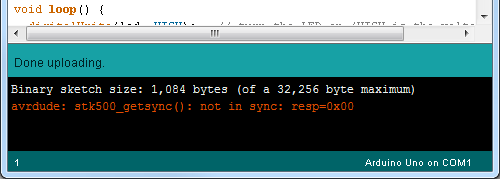
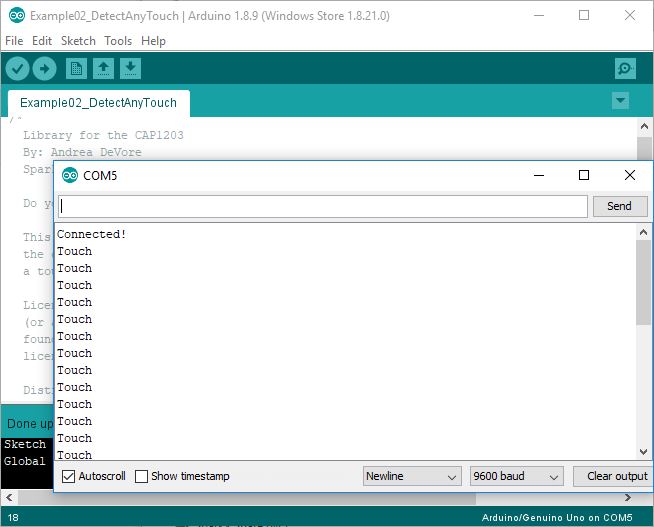
Once the code has uploaded, open the terminal window to make sure that the switch successfully connected to WiFi, and has connected to the MQTT network. If you're able to connect to the network and not the Pi, make sure the IP address is correct, as well as the credentials for Home Assistant. If both of those are right, the MQTT broker might not have been set up correctly.
MQTT Light
Copy and paste the code below into your Arduino IDE, make sure to select ESP32 Dev Module as your board, and the correct COM port is selected. Fill in the information for your WiFi credentials (your WiFi network must be on the same network as the Raspberry Pi), your user name and password for Home Assistant, and the IP address of the Pi.
language:c
/******************************************************************************
MQTT_Light_Example.ino
Example for controlling a light using MQTT
by: Alex Wende, SparkFun Electronics

This sketch connects the ESP32 Thing Plus to a MQTT broker and subcribes to the topic
room/light. When "on" is recieved, the pin LIGHT_PIN is set HIGH.
When "off" is recieved, the pin LIGHT_PIN is set LOW.
******************************************************************************/

#include <WiFi.h>
#include <PubSubClient.h>

// WiFi Network Credentials
const char *ssid = "-----";   // name of your WiFi network
const char *password = "-----"; // password of the WiFi network

// Home Assistant Credentials
const char *HA_USER = "-----";
const char *HA_PASS = "-----";

// MQTT Network
IPAddress broker(192,168,1,-); // IP address of your MQTT broker eg. 192.168.1.50
const byte LIGHT_PIN = 13;           // Pin to control the light with
const char *ID = "Example_Light";  // Name of our device, must be unique
const char *TOPIC = "room/light";  // Topic to subcribe to
const char *STATE_TOPIC = "room/light/state";  // Topic to publish the light state to


WiFiClient wclient;

PubSubClient client(wclient); // Setup MQTT client

// Handle incomming messages from the broker
void callback(char* topic, byte* payload, unsigned int length) {
  String response;

  for (int i = 0; i < length; i++) {
    response += (char)payload[i];
  }
  Serial.print("Message arrived [");
  Serial.print(topic);
  Serial.print("] ");
  Serial.println(response);
  if(response == "on")  // Turn the light on
  {
    digitalWrite(LIGHT_PIN, HIGH);
    client.publish(STATE_TOPIC,"on");
  }
  else if(response == "off")  // Turn the light off
  {
    digitalWrite(LIGHT_PIN, LOW);
    client.publish(STATE_TOPIC,"off");
  }
}

// Connect to WiFi network
void setup_wifi() {
  Serial.print("\nConnecting to ");
  Serial.println(ssid);

  WiFi.begin(ssid, password); // Connect to network

  while (WiFi.status() != WL_CONNECTED) { // Wait for connection
    delay(500);
    Serial.print(".");
  }

  Serial.println();
  Serial.println("WiFi connected");
  Serial.print("IP address: ");
  Serial.println(WiFi.localIP());
}

// Reconnect to client
void reconnect() {
  // Loop until we're reconnected
  while (!client.connected()) {
    Serial.print("Attempting MQTT connection...");
    // Attempt to connect
    if(client.connect(ID,HA_USER,HA_PASS)) {
      client.subscribe(TOPIC);
      Serial.println("connected");
      Serial.print("Subcribed to: ");
      Serial.println(TOPIC);
      Serial.println('\n');

    } else {
      Serial.println(" try again in 5 seconds");
      // Wait 5 seconds before retrying
      delay(5000);
    }
  }
}

void setup() {
  Serial.begin(115200); // Start serial communication at 115200 baud
  pinMode(LIGHT_PIN, OUTPUT); // Configure LIGHT_PIN as an output
  delay(100);
  setup_wifi(); // Connect to network
  client.setServer(broker, 1883);
  client.setCallback(callback);// Initialize the callback routine
}

void loop() {
  if (!client.connected())  // Reconnect if connection is lost
  {
    reconnect();
  }
  client.loop();
}
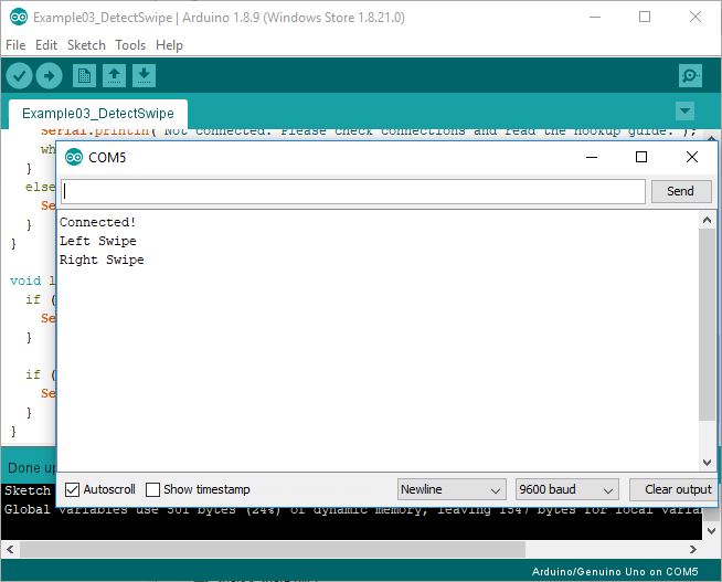
Once the code has uploaded, open the terminal window to make sure that the light successfully connected to WiFi, and has connected to the MQTT network. Once both devices have connected, you can press the button connected to IO pin 0 of the ESP32 Thing Plus acting as a switch and the LED on IO pin 13 of the light should turn on. Pressing the button a second time should turn off the LED.
Example 1.5: Controlling the ESP32 from Home Assistant
In the first example, we connected two ESP32 Thing Plus boards to Home Assistant's Mosquitto broker. Even though the server is running in the background, Home Assistant doesn't know what topics the Thing Plus boards are subscribing and publishing to. To fix that, we'll need to get Home Assistant to subscribe to those same topics, which is done by adding the components to the configuration file. Go back to the configurator tab and open the configuration.yaml file again.
The first device we'll add is the switch component, just like when we added the MQTT component, it doesn't matter where we add the switch to the configuration file, but to keep things organized, we'll add the following lines below the mqtt initialization.
switch:
  - platform: mqtt
    name: "Example_Switch"
    command_topic: "room/light"
    payload_on: "on"
    payload_off: "off"
First we told the Home Assistant that we would like to add a switch component. The switch uses the MQTT platform, and has a name called "Example_Switch". The switch will command (or publish to) a topic called "room/light", this is the same name of the mqtt topic we're publishing to in the ESP32's Switch Arduino sketch. The payload is the message being sent over the command topic to turn the light on and off.
The second device we'll add is the light component just below the switch component with an empty line separating the switch component with the light component.
light:
  - platform: mqtt
    name: "Example_Light"
    command_topic: "room/light"
    state_topic: "room/light/state"
    payload_on: "on"
    payload_off: "off"
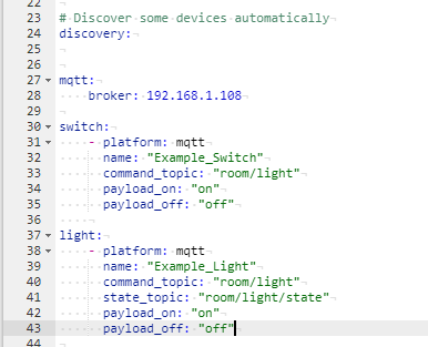
Similarly to the switch component, we told Home Assistant that we would like to add a light component. The light uses the MQTT platform, and has a name called "Example_Light". The light will listen for commands from the topic "room/light", which is the same topic we defined in the ESP32's Light Arduino sketch. The payload we're listening for is "on" to turn the light on, and "off" to turn the light off. Once those lines have been added, your configuration file should look like this:
Click the image for a closer look.
Once the light and switch components have been added, we'll need to save the configuration file again, check that the configuration valid, and restart the server. Once the server has been restarted click Overview from the left menu bar. From the there you should see your light and switch components, if not you may need to troubleshoot.
If you're able to see your components, clicking on the slide switch of the light or the lightning bolt symbol of the switch will turn the ESP32's LED on. You'll also see that from Home Assistant, the light bulb symbol of the light also turned on. Home Assistant is able to know what the state is of the MQTT light by using the state_topic both in the configuration file as well as publishing to the topic from the light's Arduino sketch. If we had removed the state_topic from the light, we would be able to control the light, but we wouldn't be able see from Home Assistant if the light is on or off.
So we can add our own devices, and that's cool I guess, but that was basically working in the MQTT tutorial. So why use Home Assistant? The next example will show that you can not only add your own devices, but devices you can buy and get working out of the box.
Troubleshooting Tips
Unused Entities
If you're not able to see your light and switch, they may be in your unused entities. To view them, click on the 3 vertical dots along the top right and select Unused entities as shown below. Or click on following link to load your unused entities page (http://hassio.local:8123/lovelace/hass-unused-entities).
Click the image for a closer look.
From this page you'll see all of your unused entities, including the Example_Light and Example Switch:
Click the image for a closer look.
Components Not Showing Up in Either
If you still can see all of your components, the issue may be your MQTT broker. To fix this, go into the configurator and open your configuration file. From the configuration file, remove the MQTT component and broker IP address, but leave the light and switch components. When done press save, and restart the server. Once it comes back online, click on configuration on the left menu bar, and click on integrations (http://hassio.local:8123/config/integrations/dashboard).
Click the image for a closer look.
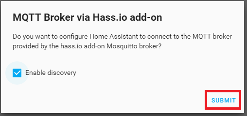
If your Mosquitto broker add-on is enabled and running, you should see a MQTT component in the discovery section; click Configure.
Click the image for a closer look.
From this page, you can check the enable discovery box and press submit. And your devices should now be visible either from the overview or unused entities pages.
Example 2: Adding Commercial Switches
In our first example we added devices to Home Assistant using devices that we programmed ourselves. Adding devices that are commercially available is even easier. In this example we're going to be adding WiFi plug switches that can easily be bought online. To see what devices are currently supported from Home Assistant, check out the components page. From there you can find popular manufacturers such as Amazon Alexa, Nest, SmartThings, Wink, WeMo, and much much more. If you don't immediately see your device, you can try searching for your device under the left side bar based on its function.
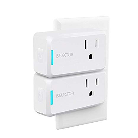
In this example we'll be adding smart plugs under the brand iSelector. There wasn't anything special about them, just an inexpensive wifi plug switch which works with the Amazon Alexa and Google Assistant. They do require that you download the app to connect the plugs to your wireless network. If you're searching for your own smart devices and aren't sure if they'll work with Home Assistant, a Google search with the device + Home Assistant should at the very least give you some Home Assistant forum questions with answers to help you decide.
Image courtesy of Amazon.com
With the iSelector plugs, they use an app called Smart Life, which requires you to sign up for a free account. We'll need the name of the app and our login credentials when we add the plugs to Home Assistant.
Adding the Plugs to Home Assistant
Once you have a compatible device and have added it to your network, it's time to integrate it with Home Assistant. iSelector devices work under the Tuya light component, so to add the device we'll the following to our configuration file after our MQTT light:
tuya:
    username: "USERNAME"    # Replace with your username
    password: "PASSWORD"    # Replace with your password
    country_code: "1"       # The country code you used to register. USA is 1
    platform: "smart_life"  # The name of the app used to create the account
After adding those lines, our configuration.yaml file should look like this:
Once again, save the configuration file, check the configuration, and restart the server. When the server comes back online, you can navigate back over to the Overview's unused entities and you should see your devices added under switches. Clicking on the slider will turn the switch on and off.
Click the image for a closer look.
Example 3: Automations
If you're familiar with If This Then That (IFTTT) automations, they work very similarly. Automations consist of three parts: The trigger which starts the processing of an automation rule, the optional conditions which can be used to prevent an action from happening when triggered (e.g. only during a certain time, or only if a switch is currently on or off), and actions which Home Assistant will do when the automation is triggered.
In this example we'll create an automation to be triggered from the first MQTT example to toggle the Wifi Plug of the second example to show how to use Home Assistant to take a device that you made and programmed to control a commercially available device, or in our case a WiFi plug switch.
Creating an Automation
To create an automation, you can either use the configurator tool to edit the automations.yaml file, or in this case, use the automations tool to generate the code. To create an automation, select configuration from the left menu bar, and click automation (or go to http://hassio.local:8123/config/automation) and click the "Add Automation" button from the bottom right.
Click the image for a closer look.
The first thing we need to do is to give the automation a name. The name is only used to remember what the automation does, so we can simply put "MQTT -> WiFi Plug". For the trigger, we'll select MQTT as the trigger type, with the topic set to "room/plug", and for the payload enter "toggle".
Click the image for a closer look.
We won't need to add any conditions to the automation, so for the actions we'll set the action type to "Call service". For the service we'll select "switch.toggle", and for our service data we'll enter "{ "entity_id": "switch.xxxxxxxxxxxxx" }" where the x's represent your plug's serial number. When done press the save button in the lower right, and go back to configuration -> general and check the config and restart the server.
Click the image for a closer look.
Finding the Entity ID
If you're having a hard time finding the entity ID for a device, you can look it up under the developer tools section of the left menu bar under services.
From the Services page, you can select the service "switch.toggle", and from the entity select the plug. From there you can copy all of the service data and paste that into the service data entry for your automation.
Click the image for a closer look.
ESP32 Code
As we wait for the server to restart, we need to modify the switch sketch from the first example. In the first example we sent messages over MQTT of "on" and "off" over the "room/light" topic. To get our automation to trigger correctly, we'll want to change our topic to "room/plug" and change the message we're sending to only be "toggle", to match the trigger event of our automation. Copy and paste the following code into your Arduino IDE and upload to your ESP32.
language:c
/******************************************************************************
MQTT_Switch_Example.ino
Example for controlling a light using an MQTT switch
by: Alex Wende, SparkFun Electronics

This sketch connects the ESP32 to a MQTT broker and publishes the message
"toggle" to the topic "room/plug".
******************************************************************************/

#include <WiFi.h>
#include <PubSubClient.h>

// WiFi Network Credentials
const char *ssid =  "-----";   // name of your WiFi network
const char *password =  "-----"; // password of the WiFi network

// Home Assistant Credentials
const char *HA_USER = "-----";
const char *HA_PASS = "-----";

// MQTT Network
IPAddress broker(192,168,1,-); // IP address of your MQTT broker eg. 192.168.1.50
const byte SWITCH_PIN = 0;           // Pin to control the light with
const char *ID = "Example_Switch";  // Name of our device, must be unique
const char *TOPIC = "room/plug";  // Topic to subcribe to
const char *MESSAGE = "toggle";   // Message to publish to our topic
WiFiClient wclient;

PubSubClient client(wclient); // Setup MQTT client

// Connect to WiFi network
void setup_wifi() {
  Serial.print("\nConnecting to ");
  Serial.println(ssid);

  WiFi.begin(ssid, password); // Connect to network

  while (WiFi.status() != WL_CONNECTED) { // Wait for connection
    delay(500);
    Serial.print(".");
  }

  Serial.println();
  Serial.println("WiFi connected");
  Serial.print("IP address: ");
  Serial.println(WiFi.localIP());
}

// Reconnect to client
void reconnect() {
  // Loop until we're reconnected
  while (!client.connected()) {
    Serial.print("Attempting MQTT connection...");
    // Attempt to connect
    if (client.connect(ID,HA_USER,HA_PASS)) {
      Serial.println("connected");
      Serial.print("Publishing to: ");
      Serial.println(TOPIC);
      Serial.println('\n');

    } else {
      Serial.println(" try again in 5 seconds");
      // Wait 5 seconds before retrying
      delay(5000);
    }
  }
}

void setup() {
  Serial.begin(115200); // Start serial communication at 115200 baud
  pinMode(SWITCH_PIN,INPUT);  // Configure SWITCH_Pin as an input
  digitalWrite(SWITCH_PIN,HIGH);  // enable pull-up resistor (active low)
  delay(100);
  setup_wifi(); // Connect to network
  client.setServer(broker, 1883);
}

void loop() {
  if (!client.connected())  // Reconnect if connection is lost
  {
    reconnect();
  }
  client.loop();

  // if the switch is being pressed
  if(digitalRead(SWITCH_PIN) == 0)
  {
    client.publish(TOPIC, MESSAGE);
    Serial.println((String)TOPIC + " => toggle");

    while(digitalRead(SWITCH_PIN) == 0) // Wait for switch to be released
    {
      delay(20);
    }
  }
}
Once the code has uploaded, and the server has restarted, go to your overview tab, and then go to your unused entities (http://hassio.local:8123/lovelace/hass-unused-entities) and make sure your automation is enabled. Once it is, when you push the button connected to IO pin 0 on the ESP32, the plug should toggle states.
Click the image for a closer look.
Going Further with Low Power
With a constant power source, the amount of current the ESP32 draws isn't much of a concern. But with having a WiFi remote for your switches, it's likely that battery power would be preferable to allow moving the switch anywhere you'd like. To get the most out of a battery, you'll want to draw as little current as you can, so to do this, we'll put the ESP32 in low power mode, and when the button is pressed we want to wake up the ESP32, connect to WiFi and the MQTT server, send our message and go back to sleep. With the sketch below, the ESP32 Thing Plus will draw around 5mA while in sleep mode, and draw up to 160mA when the MQTT packet is sent.
language:c
/******************************************************************************
Low_Power_MQTT_Switch_Example.ino
Example for controlling a light using an MQTT switch
by: Alex Wende, SparkFun Electronics

This sketch enters low power mode and waits for IO pin 0 to be pressed. Once
pressed, the ESP32 wakes up, connects to WiFi and the MQTT broker, and
publishes "toggle" to the topic "room/plug" and goes back to low power mode.
******************************************************************************/

#include <WiFi.h>
#include <PubSubClient.h>

// WiFi Network Credentials
const char *ssid =  "-----";   // name of your WiFi network
const char *password =  "-----"; // password of the WiFi network

// Home Assistant Credentials
const char *HA_USER = "-----";
const char *HA_PASS = "-----";

// MQTT Network
IPAddress broker(192,168,1,-); // IP address of your MQTT broker eg. 192.168.1.50
const byte SWITCH_PIN = 0;           // Pin to control the light with
const char *ID = "Example_Switch";  // Name of our device, must be unique
const char *TOPIC = "room/plug";  // Topic to subcribe to
const char *MESSAGE = "toggle";   // Message to publish to our topic
WiFiClient wclient;

PubSubClient client(wclient); // Setup MQTT client

// Connect to WiFi network
void setup_wifi() {
  Serial.print("\nConnecting to ");
  Serial.println(ssid);

  WiFi.begin(ssid, password); // Connect to network

  while (WiFi.status() != WL_CONNECTED) { // Wait for connection
    delay(10);
    Serial.print(".");
  }

  Serial.println();
  Serial.println("WiFi connected");
  Serial.print("IP address: ");
  Serial.println(WiFi.localIP());
}

// Reconnect to client
void reconnect() {
  // Loop until we're reconnected
  while (!client.connected()) {
    Serial.print("Attempting MQTT connection...");
    // Attempt to connect
    if (client.connect(ID,HA_USER,HA_PASS)) {
      Serial.println("connected");
      Serial.print("Publishing to: ");
      Serial.println(TOPIC);
      Serial.println('\n');

    } else {
      Serial.println(" try again in 5 seconds");
      // Wait 5 seconds before retrying
      delay(5000);
    }
  }
}

#define BUTTON_PIN_BITMASK 0x200000000 // 2^33 in hex

/*
Method to print the reason by which ESP32
has been awaken from sleep
*/
void wakeup_reason(){
  esp_sleep_wakeup_cause_t wakeup_reason;

  wakeup_reason = esp_sleep_get_wakeup_cause();

  if(wakeup_reason == ESP_SLEEP_WAKEUP_EXT0)
  {
    setup_wifi(); // Connect to network
    client.setServer(broker, 1883);

    if (!client.connected())  // Reconnect if connection is lost
    {
      reconnect();
    }
    client.loop();

    client.publish(TOPIC, MESSAGE);
    Serial.println((String)TOPIC + " => toggle");

    while(digitalRead(SWITCH_PIN) == 0) // Wait for switch to be released
    {
      delay(20);
    }
  }
}

void setup(){
  Serial.begin(115200);
  wakeup_reason();

  /*
  First we configure the wake up source
  We set our ESP32 to wake up for an external trigger.
  There are two types for ESP32, ext0 and ext1 .
  ext0 uses RTC_IO to wakeup thus requires RTC peripherals
  to be on while ext1 uses RTC Controller so doesnt need
  peripherals to be powered on.
  Note that using internal pullups/pulldowns also requires
  RTC peripherals to be turned on.
  */
  esp_sleep_enable_ext0_wakeup(GPIO_NUM_0,0); //1 = High, 0 = Low

  //Go to sleep now
  Serial.println("Going to sleep now");
  esp_deep_sleep_start();
}

void loop(){
  //This is not going to be called
}
When you push the button this time, you should notice a delay before the plug turns on or off. The main reason is the time it takes to connect to the WiFi network and then to the MQTT server. How else could we take this further? These examples were to demonstrate easy proof-of-concept demonstrations. By soldering a few more buttons and adding a case, you could create a remote that can turn on and off a bunch of lights, either one at a time, or by groups just by adding more automations and setting each button on the remote to send a different MQTT command.
Resources and Going Further
This guide hasn't even scratched the surface of what Home Assistant is capable of. And with the Qwiic Connect System on the ESP32 Thing Plus, you can add a ton of devices to Home Assistant without even having to wait for your soldering iron to heat up. For more information about about Home Assistant, check out some of the links below:
Need some inspiration for your next project? Check out some of these related tutorials:
WiFi IR Blaster Hookup Guide
How to assemble the WiFi IR Blaster and program it using Arduino. You'll be controlling IR devices from the web in no time!
learn.sparkfun.com |
CC BY-SA 3.0
| SparkFun Electronics | Niwot, Colorado