Introduction
Welcome to the Qwiic Kit for Raspberry Pi hookup guide. Here we are going to get started with some of the basics surrounding I2C and Python on your Raspberry Pi. Don't worry, we've done most of the work with the Python Libraries we've written for the boards in our Qwiic Kit. This kit should help you get started whether you just want to get data and display it on your Pi, display it on our OLED screen, or post it to the Internet.
In stock
KIT-15367
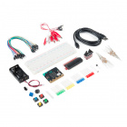
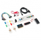
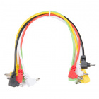
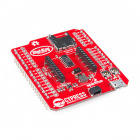
The SparkFun Qwiic Kit for Raspberry Pi includes a shield with headers, three Qwiic-enabled breakout boards, and four cables …
Required Materials
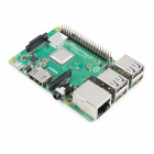
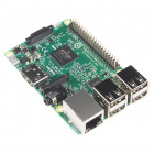
To follow along with this tutorial, you will also need a few pieces of hardware. Single board computers with the Raspberry Pi 40-pin GPIO header will work. We'll be using a Raspberry Pi throughout this tutorial. If you have not worked with a Raspberry Pi, we recommend getting started with the Raspberry Pi starter kit.
In stock
KIT-14644
There's a lot of Raspberry Pi information going around lately. Whether it’s Pi 3, Zero, Zero W or one of the many previous …
6Optional Materials
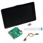
You have several options when it comes to working with the Raspberry Pi. Most commonly, the Pi is used as a standalone computer, which requires a monitor, keyboard, and mouse (listed below). To save on costs, the Pi can also be used as a headless computer (without a monitor, keyboard, and mouse). This setup has a slightly more difficult learning curve, as you will need to use the command-line interface (CLI) from another computer.
In stock
LCD-13733
This 7" Raspberry Pi Touchscreen LCD provides you with the ability to create a standalone device that can be utilized as a cu…
39In stock
PRT-14059
The SmartiPi Touch is a case and stand for the official [Raspberry Pi 7" Touchscreen LCD](https://www.sparkfun.com/products/1…
8In stock
WIG-14271
With Single-Board Computers (SBCs) on the rise, it is a good idea to have an easy way to interface with them. Operating on a …
3Suggested Reading
Before you get started, I recommend taking a look at some of our other tutorials and familiarizing yourself with some of these topics. We will end up working with the Raspberry Pi, Python programming language, and MQTT protocol to send data over the Internet.
Introduction to MQTT
An introduction to MQTT, one of the main communication protocols used with the Internet of Things (IoT).
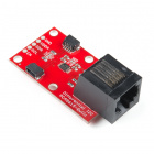
Qwiic pHAT for Raspberry Pi Hookup Guide
Get started interfacing your Qwiic enabled boards with your Raspberry Pi. This Qwiic connects the I2C bus (GND, 3.3V, SDA, and SCL) on your Raspberry Pi to an array of Qwiic connectors.
Qwiic
SparkFun's Qwiic System is a quick and easy way to connect I2C devices to your microcontroller. Because our Qwiic boards use a 4-pin JSH-SH connector, you don't need to solder. You just need a cable to connect your modules. The connector is polarized meaning you can't plug it in wrong. Additionally, you can daisy chain all your boards together.
I2C is a protocol that has been around for a while, it has a few advantages such as each device being on the same bus but each having a unique address. Messages are sent back and forth with an address and only the device with the correct address listens to the message. This is why we are able to daisy chain our sensors. Currently, a large number of sensors we find communicate over I2C, but what about the ones that don't? Well, some of our Qwiic board use other types of sensors and have a small microcontroller that reads the data and then outputs via I2C, so in other words you can make anything you want to be I2C. One thing to note is that each item on the bus must have its own address. Some sensors will have jumper pads that let you change the address (you usually have 2 or 4 options if this is the case), but not all do. This might make it difficult to have a lot of one sensor in a chain unless you have a dedicated I2C mux.
![no soldering]()
no soldering
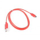
Qwiic cables (4-pin JST) plug easily from development boards to sensors, shields, accessory boards and more, making easy work of setting up a new prototype.
![]()
polarized connector
There's no need to worry about accidentally swapping the SDA and SCL wires on your breadboard. The Qwiic connector is polarized so you know you’ll have it wired correctly every time, right from the start.
![]()
daisy chain-able
It’s time to leverage the power of the I2C bus! Most Qwiic boards will have two or more connectors on them, allowing multiple devices to be connected.
The Qwiic Connect System is designed to keep your projects moving. If you have I2C sensors that don't have a Qwiic connector on them, check out our Qwiic adapter. You might have to write your own Python library, but at least we've made the connection easier for you.
Hardware
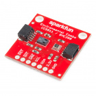
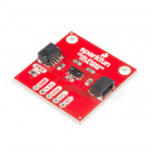
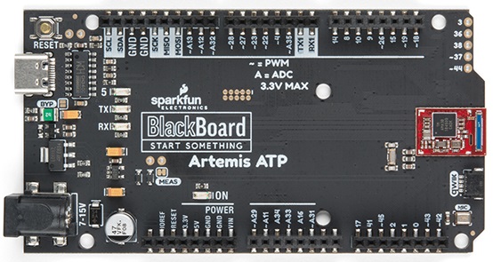
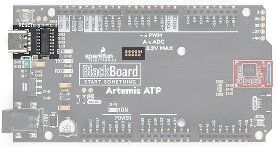
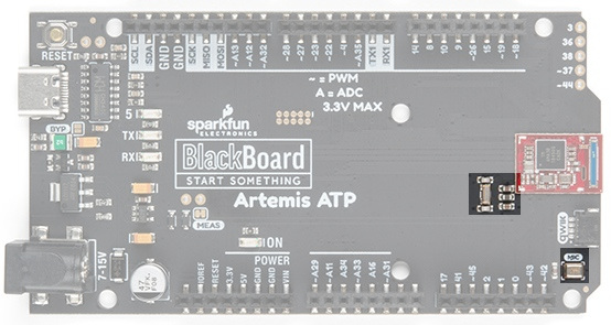
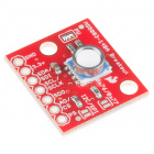
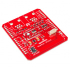
The hardware we are using for this kit (other than the Pi) is the Qwiic pHAT which provides a Qwiic connector to your Raspberry Pi, VCNL4040 Proximity sensor, Environmental combo board (which has the BME280 and CCS811), and Qwiic micro OLED screen.
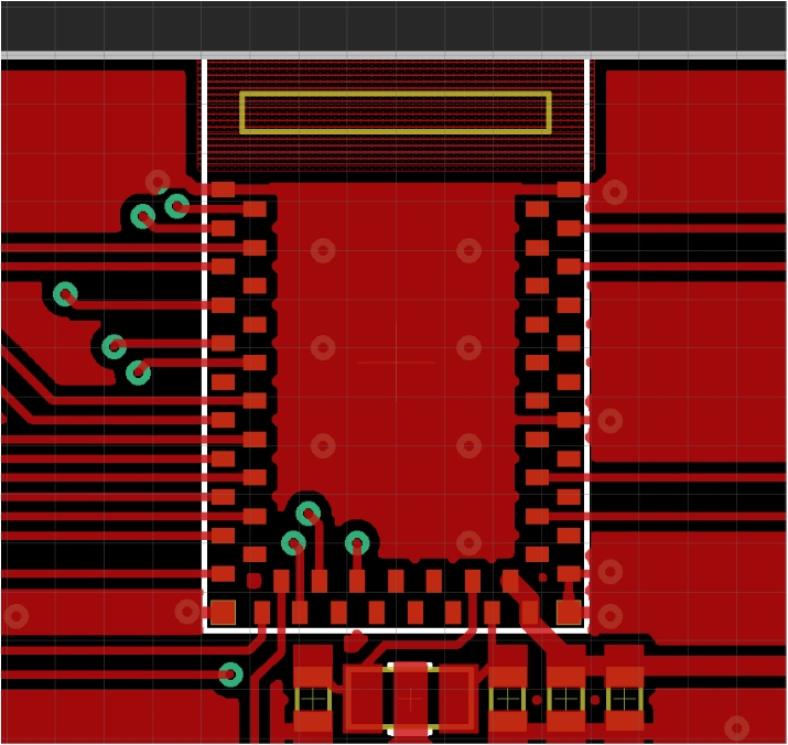
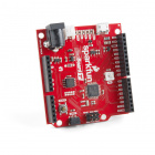
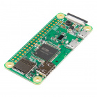
Let's start with connecting the pHAT. The pHAT should fit on the Raspberry Pi like most Pi HATs, but it should also fit on compatible boards such as the Nvidia Jetson Nano, the Google Coral board, and others that use the standard 2x20 GPIO header. It will even work on the Raspberry Pi Zero W. Just line up the headers and connect the pHAT to your Raspberry Pi. If you have more questions on the pHAT check out the hookup guide for more information.
![I2C Sensor connected to a Raspberry Pi via Qwiic pHAT]()
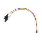
Next, we are going to connect our boards. We've given you a selection of different cable lengths to let you configure your boards however you like. So go ahead and daisy chain all your boards together (while you only need 1 Qwiic connector on the pHAT, you can use as many as you'd like). It doesn't matter which order you connect them in (or which of the connectors on the board you use), as long as they all have a path to the Pi. Keep in mind that these cables are polarized and should only go in one direction (don't force it to go in the wrong direction).
We are going to assume you already have a Raspberry Pi up and running with Raspbian. We'll also assume that it is connected to the Internet. If not, check out our starter kits and tutorials on setting up a Raspberry Pi.
Make sure to update the image so that we have the latest distribution. Enter the following commands in the command line individually to update your image.
language:bash
sudo apt-get update
sudo apt-get dist-upgrade
Note: sudo stands for "Super User Do", it is a way to give you superuser powers from the command line. Be careful whenever using sudo.
User Configuration Settings
Once you are set up, I highly recommend changing your password. At this point, we are going be dealing with the Internet of things and don't want unsavory characters sneaking into your system using the default login: (username: pi, password: raspberry).
The raspi-config tool is a quick way to change your password as well as setup the network, language, keyboard, etc. Type the following command using the command line and then go through the menus to update your information.
language:bash
sudo raspi-config
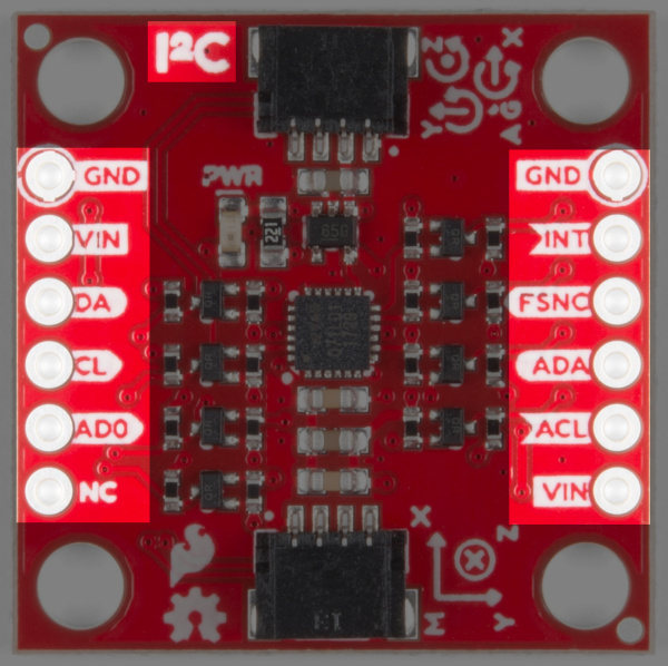
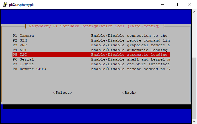
You'll want to enable the I2C pins using the tool to read the sensors on the I2C bus.
Raspi-config for I2C
I2C Clock Stretching
The CCS811 sensor requires something known as I2C clock stretching to work, so let's get this setup as well.
Open up the file /boot/config.txt in your favorite editor. We'll use the following command to edit the file through the command line.
language:bash
sudo nano /boot/config.txt
After typing the command, hit ENTER on your keyboard.
Scroll down until you find the block of code that contains the following lines. It will look similar to the following lines.
language:bash
dtparam=i2c_arm=on
dtparam=i2s=on
dtparam=spi=on
Heads up! Make sure to not add spaces before and after the "=" signs. The Pi will not be able to recognize the changes.
Add the following line(s) to enable the clock stretching.
language:bash
# Enable I2C clock stretching
dtparam=i2c_arm_baudrate=10000
When you are finished, you should see something similar to the image below.
Note: If the baud rate of 10000 is still too high, try using a slower baud rate like 5000 or 1000. After adjusting the value for clock stretching, make sure to restart your Pi for the changes to take effect.
Then save your file and exit out. We'll use the following commands CTRL+ O and then Enter to save. Then CTRL + X to exit.
You will need to restart your Pi before the settings can take effect after every change to the config.txt. After all that hard work, let's reboot your Pi with the following command.
language:bash
sudo reboot
After typing the command, hit the ENTER key.
Note: Here are some more resources on setting up a Raspberry Pi including how to connect to the Pi through a serial connection as well as VNC into the Pi remotely. This can be handy if you want to update things in the future without having to lug out an extra monitor, keyboard, and mouse.
Python
Notice: This tutorial was written with Raspbian version "June 2019", Python version 3.7.3, and pip 19.1.1 for Python v3.7. Other versions may affect how some of the steps in this guide are performed.
Python is a great language, we actually have a great tutorial on getting started with Python programming on a Raspberry Pi that covers everything from picking an editor and getting the code to run, to syntax and error messages. I highly recommend reading it if you plan on writing your own code. If you just plan on running the example code and maybe making a few changes, we'll go through a few basic things here.
Indentation
In many programming languages, we indent things to make things easier to read. In Python, those indents are part of the code. Instead of putting brackets around your loop or if() statements, you just indent that entire chunk with a leading whitespace. In other words, you have to make sure your indents are correct. I also recommend not using your keyboard's TAB button to indent as various programs will read it differently (and usually incorrectly).
Commenting
Another thing to keep in mind is comments. In Python, the symbol "#" is used to denote that the line is a comment. Unlike many other languages there is no official multi-line comment available. So you'll just have to get use to typing # for each line when writing large comments.
Python Versions and Installing PIP
There are also 2 commonly used Python versions. Even after Python 3 came out many people continued to use 2.7 for many years. Part of the reason is that Python 3 improved on some things and in the process made it not backwards compatible. For our example we will be using Python 3.7 (and the code will not run on 2.7). To see what version of Python your Pi is using, open a command line and type each of the following commands individually to check.
language:bash
python --version
pip --version
If you are not using Python 3, then we'll need to open the *.bashrc file and add an alias.
First, you will need to update the python installation package by running the following command to install pip for Python 3. Execute the following commands.
language:bash
sudo apt-get install python3-pip
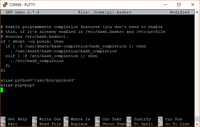
Type the following command to open the file.
language:bash
nano ~/.bashrc
Then add the following lines at the end. That should tell the computer whenever you want to run python to look for the file located at /usr/bin/python3.
language:bash
alias python='/usr/bin/python3'
alias pip=pip3
To exit nano type CTRL + X and then hit Y when it asks you if you want to save and then ENTER. You can now either reboot or type the following to force the Pi to run the *.bashrc file again.
language:bash
source ~/.bashrc
Once adjusted, type the following command to ensure that pip is up to date.
language:bash
python -m pip install --upgrade pip
Python Library
We will also need to install the Qwiic Python libraries. This will automatically download a folder containing all the Qwiic_Py files and dependencies to your Raspberry Pi. Run the following command to automatically install the modules for the Qwiic sensors and micro OLED.
language:bash
pip install sparkfun_qwiic
Setting Up MQTT and Cayenne
MQTT is a messaging protocol that works great for IoT devices. Devices can post to a topic, and/or subscribe to a topic to receive information. Alex wrote a tutorial all about MQTT, which is a great read if you are unfamiliar with MQTT. Amongst other things, our setup is going to act as an MQTT client and publish information to an online service called Cayenne.
Introduction to MQTT
An introduction to MQTT, one of the main communication protocols used with the Internet of Things (IoT).
Cayenne
Cayenne is a product from myDevices that allows you to not only display data but also set up triggers, monitor devices, control devices, etc. You can view your home's temperature remotely from their site (or app), but you can also tell it to text you when the temperature goes below 40 so you can figure out why your furnace isn't working. But don't worry, none of the exercises in this tutorial require you to give myDevices any money (or even a credit card).
If you have not already, the first thing to do is make an account. Head over to Cayenne to sign up by clicking on the link below using one of the Raspberry Pi's Internet browsers. If you have an account, just make sure to login in.
Once you have an account we're going to start by setting up the Raspberry Pi. This is a good introduction that provides you with some information on your Pi (RAM usage, temperature, network speed). It also allows you to remotely reset or shutdown you Pi, toggle I/O pins and even give you the IP address of your Pi. That is one of the nice things about Cayenne, it doesn't define devices based on IP address or network. You provide a small script and your Pi basically tells Cayenne where it is. This is helpful if you loose power, reset your device etc., and need to know the IP address to log back in remotely.
Adding a Device in Cayenne
You'll be greeted with a few devices. Select the Raspberry Pi.
You'll be prompted with an image of the Raspberry Pi before continuing on. Hit on the next button.
You'll be provided with a few options. We'll be following option 2. Follow the instructions provided (Cayenne has very good instructions in when setting up your Raspberry Pi).
At this point you should have a working Cayenne account. Type (or copy and paste using your mouse's right click) the first command and hit the ENTER button. The command will begin executing. When it is done, type (or copy and paste) the second command and hit the ENTER button. The process may take a few minutes. When the the command is finished executing, your Raspberry Pi will automatically restart.
After the reboot, open the browser back up and head back to Cayenne. Next, go back to adding a new device or widget. This time you are going to select the blue "Bring Your Own Thing" button.
This will provide you with your MQTT username, password, and client ID, as well as the server information for our project. We'll use this information later. You might want to do this on your Pi which will make it easier to copy and paste these values into your code.
Example Code
We've written some example code to read the sensor data and display a few sensor values to the micro OLED. In your terminal window, type the following to download the demo code from the GitHub repository.
language:bash
git clone https://github.com/sparkfun/Qwiic-Kit-for-Pi.git
Then navigate to folder by typing the following command in the command line.
language:bash
cd Qwiic-Kit-for-Pi
You can also navigate to the folder /home/pi/Qwiic-Kit-for-Pi to open the example in your favorite Python editor. In this case, we use opened the code in the Thonny editor.
We recommend opening the example code in a Python editor to follow along before running the demo.
Reading the Data
Now that we have everything physically hooked up and ready to go, we can set up our sensors and start reading data. First, the code will need to run through the condition statement to give the sensor values some time to take samples from the environment. At the top of the code, we set up a flag (i.e. initialize) and counter (i.e. n) to keep track of whether or not we have just started the Python script. Further down in the main code under the for loop, we'll take a few readings over a certain period of time. Once we have taken a few values, we'll update the flag so that we can take the reading once through the for loop.
language:python
#These values are used to give BME280 and CCS811 some time to take samples
initialize=True
n=2
.
.
.

        if initialize==True:
            print ("Initializing: BME280 and CCS811 are taking samples before printing and publishing data!")
            print ("")
        else:
            #print ("Finished initializing")
            n=1 #set n back to 1 to read sensor data once in loop
        for n in range (0,n):
            #print ("n = ", n) #used for debugging for loop
            .
            .
            .

            #Give some time for the BME280 and CCS811 to initialize when starting up
            if initialize==True:
                time.sleep(10)
                initialize=False
Reading the Sensors Values
Python does not require you to initialize and type your variables, we just get to go ahead and use them. We've highlighted most of the user functions in the main code under the for loop below as well as a few of the configuration functions. You'll also notice that the CCS811 has a few extra functions that read and calculate the necessary values before we actually grab them.
language:python
            #Proximity Sensor variables - these are the available read functions
            proximity = prox.getProximity()
            ambient = prox.getAmbient()
            white = prox.getWhite()
            close = prox.isClose()
            .
            .
            .

            #BME280 sensor variables
            pressure = bme.readFloatPressure() #in Pa
            altitudef = bme.readFloatAltitudeFeet()
            humidity = bme.readFloatHumidity()
            tempf = bme.readTempF()
            .
            .
            .


            #CCS811 sensor variables
            ccs.readAlgorithmResults() #updates the TVOC and CO2 values
            ccs.readNTC() #updates temp/humidity values
            tvoc = ccs.getTVOC()
            co2 = ccs.getCO2()
            ccstemp = ccs.getTemperature()
            .
            .
            .
Now that we've read all our data, let's figure out what we want to do with it all. Our different outputs will each display a different set of variables based on the application. Feel free to comment out any variables you are not using in your code using a "#" or choose to display different variables. The actual code has a lot more variables and functions listed that you probably won't need.
Display Data to Your Pi
Once we've read the data from the 3 sensors it is time to display that information on the Pi's console, the OLED screen, and send the information to be displayed by Cayenne. Let's dig into the code a bit deeper.
Comments and Libraries
Starting at the very first line you'll see a line of code that looks like a comment (comments start with #). This line actually tells us that we will by using Python 3 which is what is used for the Qwiic Pi libraries. After the header comment is a line to import a few libraries to help us keep things clean between Python 2 and Python 3. Next, we are going to add in a few libraries including an mqtt client, our Qwiic library, the time library, and the system library.
Definitions
If you scroll down a bit you'll, see our Qwiic board definitions. As we add more libraries you'll want to periodically download those updates, each sensor has its own *.py file or module. Inside that file you should find the class definition as well as all the functions. We can then setup that device in our code (the example code has already done this, but if you want to add new sensors from new libraries you'll need to do this yourself). Don't forget the begin() call to get your sensor up and running.
Then we get to the main part of our code, which is in a while() loop. This will loop forever (unless we exit out). Here is where we define and read the variables from the sensors as we talked about earlier. We do this every time through the loop so we always have new data. Next, we'll get into printing the data to the screen. We've selected some of the variables to print out as well as the time. When you run this code, this information will all display on the console.
language:python
#printing time and some variables to the screen
#https://docs.python.org/3/library/time.html
#print (time.strftime("%a %b %d %Y %H:%M:%S", time.localtime())) #24-hour time
print (time.strftime("%a %b %d %Y %I:%M:%S%p", time.localtime())) #12-hour time

print ("BME Temperature %.1f F" %tempf)
print ("Humidity %.1f" %humidity)

print ("Pressure %.2f Pa" %pressure)
print ("Altitude %.2f ft" %altitudef)

print ("CCS Temperature %.1f F" %ccstemp)
print ("Distance %.2f " %proximity)
print ("Ambient Light %.2f" %ambient)

print ("TVOC %.2f" %tvoc)
print ("CO2 %.2f" %co2)

print ("") #blank line for easier readability
Displaying Data to Your OLED
Next, we are going to look at the Qwiic micro OLED screen. The OLED module should have the same functions as our OLED Arduino library, but they might look a bit different. Let's start with a few basic commands...
Initializing the Micro OLED
We start by defining our OLED screen like we did with our sensors at the top of the code as well as run the initilization.
language:python
oled = qwiic.QwiicMicroOLED()
oled.begin()
Clearing the Screen
Next, we are going to clear the screen. This actually will clear the entire buffer.
language:python
oled.clear(oled.ALL)
Then we can display the cleared screen. This will display what is in the buffer which at this point is nothing.
language:python
oled.display()
Font Size
Next, we can set the font type. The module comes with 4 different fonts. Unless you just need to display 2-3 digits, I recommend sticking with font 0 or font 1 as they will give you enough room to display a few lines of information. This is the end of the commands we'll use to setup the screen at the beginning of the code
language:python
oled.setFontType(1)
Setting Cursor Position
When we are ready to actually print to the screen we'll set the cursor to the top left.
language:python
oled.setCursor(0,0)
Printing
Then we can print some text. When we print the temperature, we don't want to print all the decimal places, partly because the limit of the screen size. The "int" command takes the tempf variable and gives us an integer and then we can print that.
language:python
oled.print("Tmp:")
oled.print(int(tempf))
If we want, we can move the cursor to a different line, print more data, etc.
Displaying
Finally, we will want to display all of this to the screen.
language:python
oled.display()
Also, keep in mind you might want to add delays when using an OLED screen so that the information isn't flickering too fast. In this case, we already have a 1 second delay each time through the loop so we should be fine.
Because we already have the variables setup, we just need to pick a few we think would be useful and print them to our OLED display. We can get about 3 lines of code here comfortably, but you might want to change the font type and just display temperature so that you can view it from more than 12 inches away.
More with Cayenne
Now let's look at the Cayenne part of our code. Let's start with the the definitions. Remember the username, password, and client ID we got earlier? We are going to copy and paste these into the code for the respective username, password, and clientid. Now our code knows not only to post to Cayenne, but who's account and what project this is for.
language:python
username = "______ENTER_MQTT_USERNAME____"
password = "______ENTER_MQTT_PASSWORD____"
clientid = "___ENTER_CAYENNE_CLIENTE_ID___"
mqttc=mqtt.Client(client_id = clientid)
mqttc.username_pw_set(username, password = password)
mqttc.connect("mqtt.mydevices.com", port=1883, keepalive=60)
mqttc.loop_start()
Topics
Next, we are going to setup our topics. Topics are how MQTT keeps track of what is what. Each topic gets a different channel which is the number at the end of the line. Otherwise, the code is exactly the same for each topic name. We just need to figure out once at the beginning what pieces of data we want to send.
language:python
#set MQTT topics (we are not setting topics for everything)
topic_bme_temp = "v1/" + username + "/things/" + clientid + "/data/1"
topic_bme_hum = "v1/" + username + "/things/" + clientid + "/data/2"
topic_bme_pressure = "v1/" + username + "/things/" + clientid + "/data/3"
topic_bme_altitude = "v1/" + username + "/things/" + clientid + "/data/4"

topic_prox_proximity = "v1/" + username + "/things/" + clientid + "/data/5"
topic_prox_ambient = "v1/" + username + "/things/" + clientid + "/data/6"

topic_ccs_temp = "v1/" + username + "/things/" + clientid + "/data/7"
topic_ccs_tvoc = "v1/" + username + "/things/" + clientid + "/data/8"
topic_ccs_co2 = "v1/" + username + "/things/" + clientid + "/data/9"
Publishing Sensor Data to the Cloud
Once in the main part of the code, we are going to publish data to each of those topics so Cayenne will see this. You'll notice we are using the topics we set up earlier, as well as setting the payload to the variable we want to send with it.
language:python
#publishing data to Cayenne (we are not publishing everything)
mqttc.publish (topic_bme_temp, payload = tempf, retain = True)
mqttc.publish (topic_bme_hum, payload = humidity, retain = True)
mqttc.publish (topic_bme_pressure, payload = pressure, retain = True)
mqttc.publish (topic_bme_altitude, payload = altitudef, retain = True)

mqttc.publish (topic_prox_proximity, payload = proximity, retain = True)
mqttc.publish (topic_prox_ambient, payload = ambient, retain = True)

#mqttc.publish (topic_ccs_temp, payload = ccstemp, retain = True)
mqttc.publish (topic_ccs_tvoc, payload = tvoc, retain = True)
mqttc.publish (topic_ccs_co2, payload = co2, retain = True)
Let's Run the Code Already!
OK, now that we've updated our code to submit data to our Cayenne account and figured out which variables we want to send where we can run the code. Make sure you save your code (with your Cayenne account information and any other changes you wanted to make). Then open a terminal window and navigate to the folder where your code is if you have not already. Type the following command and ENTER to run the script. Our code actually runs a loop until we decide to cancel the program CTRL + C.
language:bash
python qwiic_kit_for_pi_demo.py
Or hit the Run button in your Python editor to start executing the script. To stop, simply click on the Stop button with your mouse.
Assuming you don't get any errors you should see some of the BME280 sensor data displayed on your screen and data on the OLED.
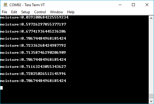
![Output via Command Line]() | ![Output via Python Editor]() |
| Running Demo via Command Line | Running Demo via Thonny Editor |
Click on images for a closer look!
Note: If you do not give the sensors enough time to start, the output for the BME280 and CCS811 may appear to be incorrect. You'll notice that the pressure and altitude may be off by about
40,000 Pa and
10,000 ft, respectively. The TVOC and CO2 values may start with
0.00 and
400.00. This is normal. You'll need to give the sensors a few seconds to take a readings from the environment. The CCS811 will take longer for the sensor values to stabilize after the burn-in and run-in values.
Thu Jun 27 2019 03:03:39PM
BME Temperature 81.3 F
Humidity 30.2
Pressure 121347.04 Pa
Altitude -5078.29 ft
CCS Temperature 80.9 F
Distance 1.00
Ambient Light 412.00
TVOC 0.00
CO2 400.00
You will also start seeing the green boxes popping up on Cayenne as well so you can add them to your dashboard and move them around.
Congratulations, you now know how to read Qwiic sensors on a Pi, display data to your Pi, display data on the Qwiic micro OLED screen, and get that information to display on the web. Try adjusting the code to send data to the web at a slower rate or calibrate the sensor readings for stable readings. Keep checking the Qwiic_Py repo for more Python libraries for our Qwiic boards or write your own and start experimenting.
Customizing Data on Cayenne's Dashboard
Once Cayenne sees this data, you should get a green box pop up on your Cayenne dashboard. Click the "+" in the upper right hand corner to permanently add it to your dashboard. By default, the values will be displayed with the associated channel. You will need to head into the settings and assign a name to be displayed for each channel in order to easily read the sensor data. You can also assign an icon to the channel, drag and drop widgets, and resize each window if you prefer.
After customizing according to your personal preference, the channels may look similar to the image below.
Triggers and Notifications
While we are not going to go into this in this tutorial, Cayenne will also let you setup triggers and other things to text you, email you, or change things on any of your other devices (such as turn on an I/O pin on the Pi). You can start playing with Cayenne and its various features. Just make sure you don't overwhelm your inbox with notifications by sending texts 100 times per second.
Troubleshooting
Below are a few additional troubleshooting tips and tricks when using the Qwiic devices with a single board computer.
The Demo Code is Not Running.
If you are having trouble running the demo code, there are a few reasons why the Python script may not be executing. Below are two common reasons why the demo code may not be running.
Library Not Installed
If the libraries are not installed properly, you may receive an error similar to the output below when trying to execute the Python script:
language:bash
 Traceback (most recent call last):
  File "./qwiic_kit_for_pi_demo.py", line 24, in <module>
    import qwiic
ImportError: No module named 'qwiic'
The ImportError indicates that the module(s) was not installed properly. Make sure that the Python modules are installed on the Pi in order to run the demo.
I2C Device Not Connected
If you receive an error similar to the one below, it means that the bus is having issues reading the sensor.
language:bash
Traceback (most recent call last):
  File "/home/pi/qwiicpy/qwiic_kit_for_pi_demo.py",     line 117, in <module>
    ccs.readAlgorithmResults() #updates the TVOC and CO2 values
  File "/home/pi/qwiicpy/qwiic/qwiic_ccs811.py", line 159, in readAlgorithmResults
    data = self.readBlock(CSS811_ALG_RESULT_DATA, 4)
  File "/home/pi/qwiicpy/qwiic/qwiicdevice.py", line 119, in readBlock
    return self._i2cDriver.readBlock(self.address, commandCode, nBytes)
  File "/home/pi/qwiicpy/qwiic/qwiic_i2c/linux_i2c.py", line 144, in readBlock
    return self.i2cbus.read_i2c_block_data(address, commandCode, nBytes)
OSError: [Errno 121] Remote I/O error
The OSError: [Errno 121] Remote I/O error indicates that an I2C device is not connected to the bus. Make sure that the sensors and micro OLED are securely connected to the I2C bus. The demo code currently checks to see if the CCS811, BME280, VCNL4040, and micro OLED are connected to the Pi's I2C bus before executing.
Don't forget to setup the clock stretching for the Raspberry Pi, this is required for the CCS811 to work correctly on the bus. If 10000 is still too fast, try using a slower baud rate. Make sure to reboot for the changes to take effect.
If you receive this error, this is because there is no NTC thermistor connected! You will not want to call this function.
language:bash
Traceback (most recent call last):
  File "/home/pi/Qwiic-Kit-for-Pi/qwiic_kit_for_pi_demo.py", line 128, in <module>
    ccs.readNTC() #updates temp value
  File "/home/pi/.local/lib/python3.7/site-packages/qwiic_ccs811.py", line 356, in readNTC
    self.resistance = self.ntcCounts * self.refResistance / float(self.vrefCounts)
ZeroDivisionError: float division by zero
I'm Having Problems Getting the Qwiic_Py Library.
If you are having trouble installing the modules, you may receive this error:
Could not install packages due to an EnvironmentError: 404 Client Error: Not Found for url: https://www.piwheels.org/simple/sparkfun-qwiic/
Make sure that you are connected to the Internet to install the modules. Also, make sure that you are using Python3 and pip3 with the correct alias as stated earlier.
language:bash
python -m pip install --upgrade pip
I Don't Want to Use Cayenne or Another 3rd Party Service.
That's perfectly alright, you can delete or comment out all the relevant commands as that is not will not affect the rest of the code.
I Can't Connect to Cayenne.
Make sure you have copied your username, password, and clientid correctly from Cayenne into the code before executing the Python script.
How do I add _____ Qwiic sensor.
Right now we only have a few Qwiic sensors in the Qwiic Py library, but we are looking to keep adding more. Please periodically check back to see if the sensor you want is available. You can also check the Internet for existing Python code for that sensor or write your own library.
Resources and Going Further
For more information, check out the resources below:
Looking for more inspiration? Check out these other Raspberry Pi projects and Python tutorials.:
Python GUI Guide: Introduction to Tkinter
Tkinter is the standard graphical user interface package that comes with Python. This tutorial will show you how to create basic windowed applications as well as complete full-screen dashboard examples complete with live graph updates from matplotlib.
Pi AVR Programmer HAT Hookup Guide
In this tutorial, we will use a Raspberry Pi 3 and the Pi AVR Programmer HAT to program an ATMega328P target. We are going to first program the Arduino bootloader over SPI, and then upload an Arduino sketch over a USB serial COM port.
New!TPL5110 Nano Power Timer Hookup Guide
The TPL5110 Nano Power Timer is ideal for applications that require low power, and especially those projects that are running off of a LiPo battery. The Nano Power Timer will turn on your project after the set amount of time, continuously.
Or check out some of these blog posts for ideas:
learn.sparkfun.com |
CC BY-SA 3.0
| SparkFun Electronics | Niwot, Colorado