Introduction
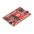
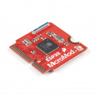
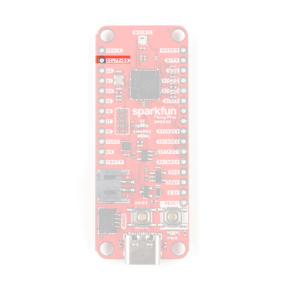
Introducing the SparkFun Thing Plus - RP2040, featuring the RP2040 microcontroller (MCU) on a Feather (Thing Plus) form-factor. Additionally, this development platform also provides an SD card slot, 16MB (128Mbit) flash memory, a JST single cell battery connector (with a charging circuit and attached fuel gauge sensor), a WS2812 RGB LED, JTAG (PTH) pins, and our signature Qwiic connector.
Pre-Order
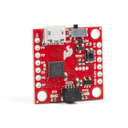
DEV-17745
The SparkFun Thing Plus - RP2040 is a low-cost, high performance board with flexible digital interfaces featuring the Raspber…
The Raspberry Pi RP2040(the first MCU from the Raspberry Pi Foundation) is a low cost, dual-core Arm® Cortex® M0+ microcontroller with 264kB of SRAM, running at 133MHz. It includes USB host functionality, a timer with 4 alarms, a real time counter (RTC), six dedicated IO pins for Quad-SPI flash (supporting execute in place), and thirty multifunction GPIO (*18 of which are broken out on the board), with the following capabilities:
- Four 12-bit Analogue to Digital Converter (ADC) channels
- Two UART buses
- Two I2C buses
- Two SPI buses
- Up to 16 PWM channels
- Can emulate interfaces such as SD Card and VGA
Required Materials
To get started, users will need a few items. Now some users may have a few of these items, feel free to modify your cart accordingly.
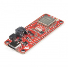
- SparkFun Thing Plus - RP2040
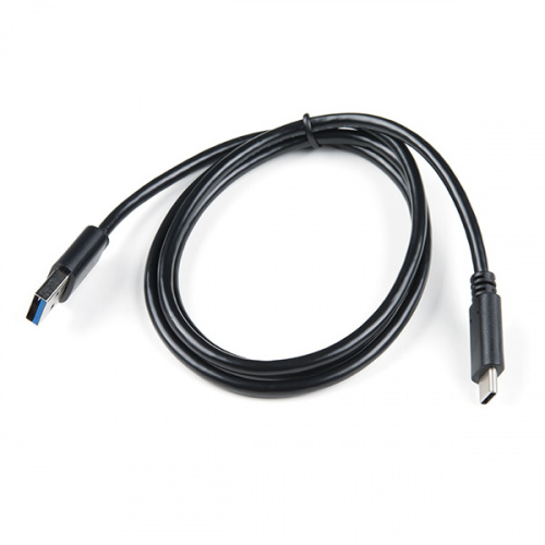
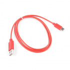
- USB 3.1 Cable A to C - 3 Foot - The USB interface serves two purposes: it powers the board and allows you to upload programs to it. (*If your computer doesn't provide a USB-A slot, then you will need to choose an appropriate cable or purchase an adapter as well.)
- Computer with the an operating system (OS) that is compatible with all the software installation requirements:
- Windows 10
- Mac OSX
- Raspberry Pi OS
In stock
CAB-14743
USB C is fantastic. But until we have converted all our hubs, chargers, and ports over to USB C this is the cable you're goin…
2Pre-Order
DEV-17745
The SparkFun Thing Plus - RP2040 is a low-cost, high performance board with flexible digital interfaces featuring the Raspber…
BatteriesJumper ModificationHeaders & Accessories
Click the buttons above to toggle the additional materials based on the tasks you
wish to perform. Feel free to modify the items in your cart to fit your needs.Li-Po Battery
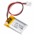
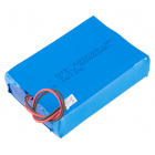
For mobile applications, users will want to pick up a single-cell LiPo battery from our catalog. Below, are a few available options:
Out of stock
PRT-13851
This is a very small, extremely lightweight battery based on Lithium Ion chemistry, with the highest energy density currently…
9In stock
PRT-13855
These are very slim, extremely light weight batteries based on Lithium Ion chemistry. Each cell outputs a nominal 3.7V at 200…
7In stock
PRT-13813
Slim, extremely light weight batteries based on Lithium Ion chemistry. Each cell outputs a nominal 3.7V at 1000 mAh!
7Out of stock
PRT-13853
This is a very small, extremely light weight battery based on Lithium Ion chemistry. This is the highest energy density curre…
2Jumper Modification
To modify the jumpers, users will need soldering equipment and/or a knife.
In stock
TOL-09325
This is your basic spool of lead free solder with a water soluble resin core. 0.031" gauge and 100 grams. This is a good spoo…
7In stock
TOL-14579
This 10mL no-clean flux pen from Chip Quik is great for all of your solder, de-solder, rework, and reflow purposes!
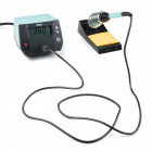
3Only 7 left!
TOL-14228
The WLC100 from Weller is a versatile 5 watt to 40 watt soldering station that is perfect for hobbyists, DIYers and students.…
1In stock
TOL-09200
It's like an Xacto knife, only better. We use these extensively when working with PCBs. These small knives work well for cutt…
2Qwiic Example
If you would like to follow along with the examples below to interact with the physical world, you will also need the following items:
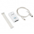
In stock
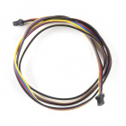
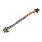
PRT-14427
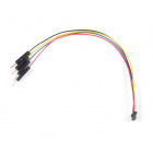
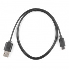
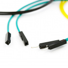
This is a 100mm long 4-conductor cable with 1mm JST termination. It’s designed to connect Qwiic enabled components together…
In stock
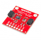
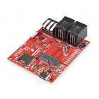
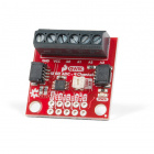
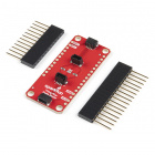
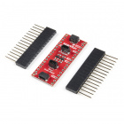
DEV-15334
The SparkFun Qwiic 12 Bit ADC can provide four channels of I2C controlled ADC input to your Qwiic enabled project.
In stock
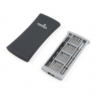
TOL-15003
This is a 20 piece screwdriver set that magnetically keeps each of the unused bits secured inside of a thin case that easily …
1JTAG Functionality
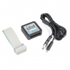
Users interested in JTAG applications (i.e. programming and debugging the RP2040) will need an Arm® Programmer and need to solder on a JTAG header. We recommend these programmers from our catalog:
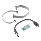
20 available
PGM-15346
J-Link programmer for programming any ARM microconroller. Comes with an educational/ non-commercial license.
In stock
PGM-15345
Tiny J-Link programmer for programming any ARM microconroller. Comes with an educational/ non-commercial license.
1Out of stock
PGM-15347
Compact J-Link programmer for programming any ARM microconroller.
In stock
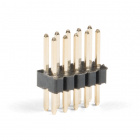
PRT-15362
This is a super small, 2x5 pin male PTH header. This header is in the common configuration for JTAG applications.
Suggested Reading
Here are a few tutorials that may help users familiarize themselves with various aspects of the board.
Serial Communication
Asynchronous serial communication concepts: packets, signal levels, baud rates, UARTs and more!
Battery Technologies
The basics behind the batteries used in portable electronic devices: LiPo, NiMH, coin cells, and alkaline.
Logic Levels
Learn the difference between 3.3V and 5V devices and logic levels.
I2C
An introduction to I2C, one of the main embedded communications protocols in use today.
Analog vs. Digital
This tutorial covers the concept of analog and digital signals, as they relate to electronics.
One of the new, convenient features of the board is that it takes advantage of the Qwiic connect system. We recommend familiarizing yourself with the Logic Levels and I2C tutorials. Click on the banner above to learn more about Qwiic products.
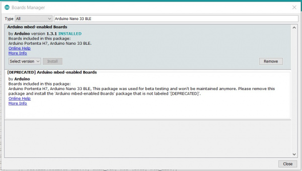
UF2 Bootloader
The SparkFun Thing Plus - RP2040 is easy to program, thanks the UF2 bootloader. With the UF2 bootloader, the RP2040 Thing Plus shows up on your computer as a USB storage device without having to install drivers for Windows 10, Mac, and Linux!
Board being recognized as a USB device. (Click to enlarge)
What is UF2?
UF2 stands for USB Flashing Format, which was developed by Microsoft for PXT (now known as MakeCode) for flashing microcontrollers over the Mass Storage Class (MSC), just like a removable flash drive. The file format is unique, so unfortunately, you cannot simply drag and drop any compiled binary or hex file onto the board. Instead, the format of the file must have specific information to tell the processor where the data goes, in addition to the data itself. For more information about UF2, you can read more from the MakeCode blog, as well as the UF2 file format specifiation.
BOOTSEL Mode
Users can enter BOOTSEL mode by holding down the BOOT button, when the USB connection is made to a computer. The board will remain in this mode until it power cycles (happens automatically after uploading a .uf2 firmware file) or the RESET button is pressed. The board will appear as a USB mass storage device under the name RPI-RP2.
Hold down BOOT button to enter BOOTSEL mode.
Hardware Overview
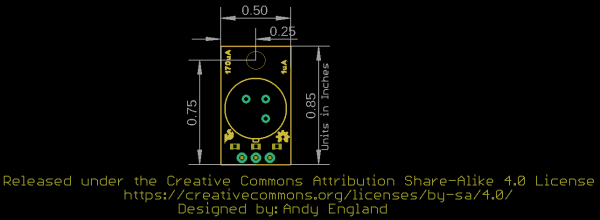
Board Dimensions
The SparkFun RP2040 Thing Plus has a feather form factor and the board dimensions are illustrated in the drawing below.
Board dimensions (PDF) for the SparkFun RP2040 Thing Plus, in inches. (Click to enlarge) Power
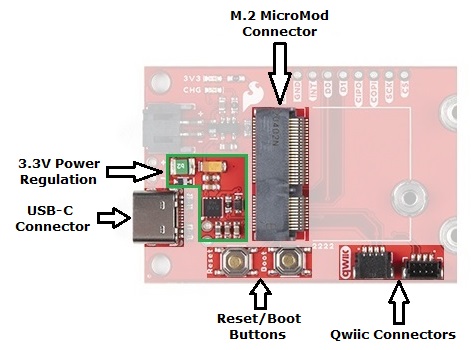
The SparkFun RP2040 Thing Plus only requires 3.3V to power the board. However, the simplest method to power the board is through the USB-C connector.
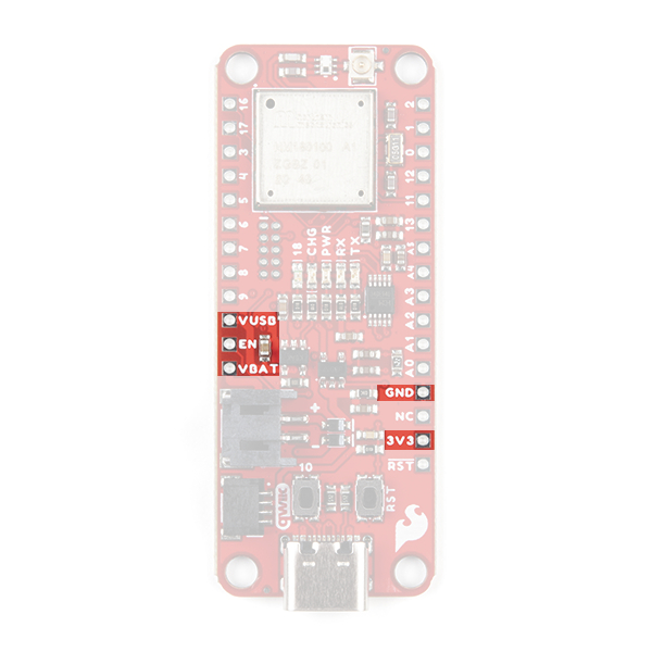
SparkFun RP2040 Thing Plus power connections. (Click to enlarge)
The power pins that are available on the board, are detailed below:
3V3 - A regulated 3.3V voltage source (600mA).
- Regulated from the USB 5V power and/or battery connection by a AP2112 LDO.
- Used to power the RP2040 MCU, WS2812 RGB LED, W25Q128 16MB flash chip, µSD card slot, and Qwiic I2C bus.
- Serves as the reference voltage for the RP2040 ADC (
ADC_VDD). - Pin can also operate as an input from an external power source.
USB - The voltage from the USB-C connector, usually 5V.
VBAT - The voltage from the JST battery connector; meant for single cell LiPo batteries.
- Used to provide a regulated 3.3V source through the AP2112 LDO (see above).
- Connected to the MCP73831 linear charge management controller.
GND - The common ground or the 0V reference for the voltage supplies.
![Power Pins]()
SparkFun RP2040 Thing Plus power pins. (Click to enlarge)
Current Consumption
The Thing Plus - RP2040 consumes about 24mA on average, without any code running. The table below, summarizes the approximate current draw of the SparkFun RP2040 Thing Plus, through the USB-C connector, for various operational conditions.
| Operation | 1st Boot | BOOTSEL Mode | Idle | Idle | MicroPython |
|---|
| Battery Charging | GPIO 25
LED ON
|
WS2812 LED
White (max) | .uf2 Boot | REPL Open |
| Current Draw (mA) |
11 (Idle)
20 (Peak)
|
11-14
|
--
|
--
|
25
|
40-42
|
22-24
|
23-24
|
|---|
Note: The RP2040 microcontroller has two low power states:
SLEEP - All the processors are asleep and most of the clocks in the chip are stoppedDORMANT - All clocks in the chip are stopped
The real-time clock (RTC) can wake the RP2040 chip up from both of these modes. However, to wake the chip from dormant mode, the RTC must be configured to use an external reference clock, supplied by a GPIO pin.
Power Status LED
The red, POWER LED will light up once 3.3V is supplied to the board; however, for most users, it will light up when 5V is supplied through the USB connection or when a LiPo battery is connected to the JST connector.
SparkFun RP2040 Thing Plus POWER status LED indicator. (Click to enlarge)
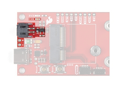
Charging Circuit
The charging circuit utilizes the MCP73831 linear charge management controller and is powered directly from the USB-C connector or USB. The controller is configured for a 500mA charge rate and battery charging is indicated when the yellow, CHG LED. If the charge controller is shutdown or charging is complete, the CHG LED will turn off. For more information, pleas refer to the MCP73831 datasheet.
Charging circuit for the battery connector. (Click to enlarge)
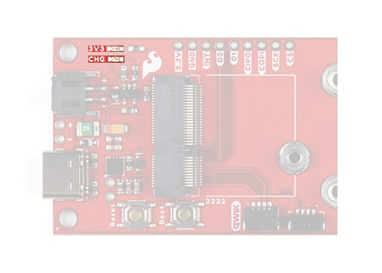
Power Control
The power source to the AP2112 LDO voltage regulator is controlled by a P-channel MOSFET. In addition, the 3.3V regulated output from the AP2112 is controlled by the enable (EN) pin, broken out on the board.
Circuit for 3.3V power control. (Click to enlarge)
The P-channel MOSFET operation is based on the voltages at the MOSFET's gate and source pins. Depending on the power sources connected to the board, the MOSFET will act as a switch and control power from the battery to the AP2112 voltage regulator; detailed in the following table.
| Power Source | MOSFET | Power Control Description |
|---|
| Gate | Source | VGS |
MOSFET
Operation
|
|---|
USC-C
VUSB = 5V
|
Battery
VBatt = 3 - 4.2V
|
VGate - VSource
VUSB - VBatt |
| USB Only | X | -- | VGS = 5V |
MOSFET Off
RGS = ∞
Switch Open
| Power to the AP2112 is supplied by the USC-C connection.
The MOSFET operation doesn't matter in this situation. However, power from the USB-C connection creates a positive gate threshold voltage and the MOSFET would behave as an open switch.
|
| Battery Only | -- | X | -3V > VGS> -4.2V |
MOSFET On
RGS = Low
Switch Closed
| Power to the AP2112 is supplied from the battery connection.
Power from the battery creates a negative gate threshold voltage. Therefore, the MOSFET acts like a closed switch and power to the AP2112 is provided from the battery.
|
| USB & Battery | X | X | .8V < VGS< 2V |
MOSFET Off
RGS = ∞
Switch Open
| Power to the AP2112 is supplied from the USC-C connection.
Power from the USB-C connection and battery would create a positive gate threshold voltage. Therefore, the MOSFET operate as an open switch and only allow power from the USB-C connection to the AP2112. Meanwhile, if the battery wasn't fully charged, the charging circuit would also be powered by the USC-C connection.
|
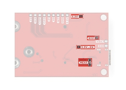
The enable pin of the AP2112 LDO also provides an additional amount of control for power to the board. By default, the chip enable pin (EN) is pulled high, to enable the 3.3V output, supply voltage. To disable and shutdown the output voltage from the AP2112, the chip enable pin (EN) needs to be pulled low (i.e. shorted to ground (GND)). For more information, pleas refer to the AP2112 datasheet.
Enable pin on the SparkFun RP2040 Thing Plus. (Click to enlarge)
Protection
A BAT20J Schottky diode, in the power circuit, provides reverse current protection to the USB-C (VUSB) connector, from the battery (VBAT) or the board.
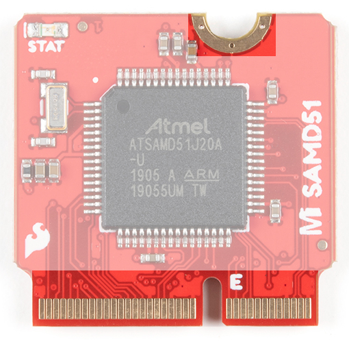
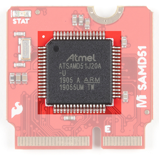
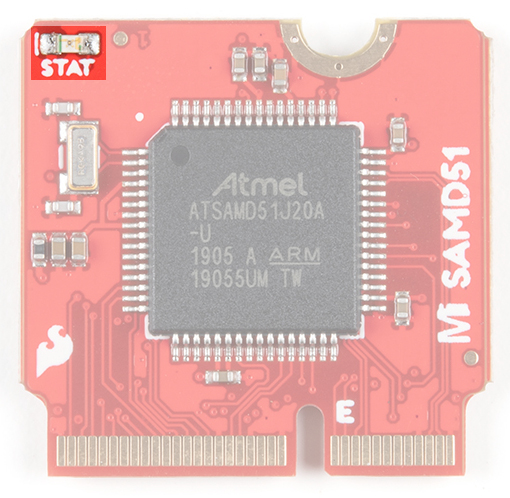
RP2040 Microcontroller
The Raspberry Pi RP2040 is a low-cost, high-performance microcontroller with flexible digital interfaces. It features:
- Dual Arm® Cortex®-M0+ processors, up to 133 MHz
- 264 kB of embedded SRAM in 6 banks
- 6 dedicated IO for additional storage
- Connects to QSPI Flash
- Supports execute in place (XIP))
- 30x 3.3V user-programmable high-speed IO (only 18 are broken out on the board)
- 4x 12-bit 500ksps Analogue to Digital Converter (ADC)
- Various digital peripherals
- 2x UART, 2x I2C, 2x SPI, up to 16 PWM channels
- 1x Timer with 4 alarms, 1x Real Time Counter
- USB 1.1 Host/Device compatible
RP2040 on the SparkFun RP2040 Thing Plus. (Click to enlarge)
The processor implements the ARMv6-M Thumb instruction set and provides programmable (multifunction) IO (PIO), which is unique to the RP2040. For more information, pleas refer to the RP2040 datasheet.
JTAG Pins
Note: Currently there isn't support for the RP2040, using J-Link ARM programmers. The current recommended debug hardware is a second RP2040 microcontroller.
For users interested in debugging their code, the SWD pins are broken out on JTAG PTH pins. On the RP2040, the debug pins are:
- Pin 24:
SWCLK - Pin 25:
SWDIO
JTAG pins on the SparkFun RP2040 Thing Plus. (Click to enlarge)
An individual debug access port (DAP) to each core is attached to a shared multidrop SWD bus. Each DAP will
only respond to debug commands if correctly addressed by a SWD TARGETSEL command. In the event that the RP2040 locks up, a Rescue debug port is available to reset the microcontroller. The default address of each debug port is listed below:
- Core 0:
0x01002927 - Core 1:
0x11002927 - Rescue DP:
0xf1002927
Rescue Debug Port Reset: The RP2040 can be reset through a Rescue Debug Port, allowing users to recover the
Thing Plus - RP2040 from a locked up state. A Rescue Debug Port reset configures the
PSM_RESTART_FLAG of the
CHIP_RESET register and resets the RP2040. On startup, the
CHIP_RESET register is read by the bootcode and when set, it causes the RP2040 to enter a safe state.
USB Functionality
The RP2040 contains a USB 2.0 controller that can operate as either:
- Full Speed device (12 Mbit/s)
- Host that can communicate with both Low Speed (1.5 Mbit/s) and Full Speed devices. This includes multiple
downstream devices connected to a USB hub.
USB Mass Storage Interface
The Bootrom provides a standard USB bootloader that emulates a writeable drive available for loading firmware to the RP2040
using UF2 files. Once a UF2 file is loaded onto the drive, it is written to the flash or RAM and the device automatically reboots.
- The bootrom source code is hosted on GitHub.
RPI-RP2 Drive
The RP2040 appears as a standard 128MB flash drive named RPI-RP2 formatted as a single partition with FAT16. There
are only ever two actual files visible on the drive specified.
INFO_UF2.TXT - contains a string description of the UF2 bootloader and version.INDEX.HTM - redirects to information about the RP2040 device.
Note: Any type of files may be written to the USB drive from the host computer, however in general these are not stored, and only appear to be so because of caching on the host side. When a .uf2 file is written to the device however, the special contents are recognized and data is written to specified locations in RAM or Flash. On the completed download of an entire valid .uf2 file, the RP2040 automatically reboots to run the newly downloaded code.
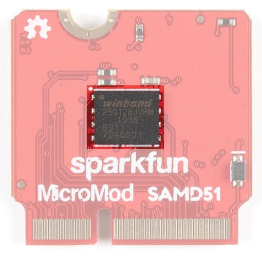
Flash Memory
RP2040 has embedded ROM and SRAM, and access to external flash via a QSPI interface. On the SparkFun RP2040 Thing Plus, an additional 16MB (128Mbit) of 133MHz memory is provided by a W25Q128JVPIM chip. The flash memory is required for the RP200 to store program code, which it can boot and run from through its dedicated QSPI pins:
- Pin 52:
CLK - Pin 56:
CS - Pin 53:
DATA 0 - Pin 55:
DATA 1 - Pin 54:
DATA 2 - Pin 51:
DATA 3
W25Q128JVPIM flash memory on the SparkFun RP2040 Thing Plus. (Click to enlarge)
Note: The RP2040 is able to access up to a 16MB memory window starting at 0x10000000.
Indicator LEDs
There are 4 indication LEDs on the SparkFun RP2040 Thing Plus for:
PWR: Power (Red)CHG: Battery Charging (Yellow)25:GPIO 25 (Blue)WS2812:GPIO 08 (RGB)
Power LED
The red, PWR LED will light up once 3.3V is supplied to the board. For most users, it will light up when 5V is supplied through the USB connection and/or when a LiPo battery is attached to the JST connector.
SparkFun RP2040 Thing Plus PWR status LED indicator. (Click to enlarge)
Battery Charging LED
The yellow, CHG LED will light while a battery is being charged through the charging circuit. The LED will be on when no battery is present, when the charge management controller is in standby (after the battery charging has been completed), or when the charge management controller is shutdown (thermal shutdown or when the input voltage is lower than the battery voltage). The LED will be off when the charge management controller is in the process of charging the battery. For more information, please refer to the MCP73831 datasheet.
![Charge LED]() The battery charging (`CHG`) LED indicator on the SparkFun RP2040 Thing Plus. (Click to enlarge)
The battery charging (`CHG`) LED indicator on the SparkFun RP2040 Thing Plus. (Click to enlarge)| Charge Cycle State | STAT1 |
|---|
Shutdown
- Thermal Shutdown
- VDD< VBAT
| Off (High Z) |
| No Battery Present | Dimmed (High Z) |
| Charge Complete – Standby | Off (H) |
| Preconditioning | On (L) |
| Constant-Current Fast Charge | On (L) |
| Constant Voltage | On (L) |
Status LED
The blue, 25 LED is typically used as a test or status LED to make sure that a board is working or for basic debugging. This indicator is connected to GPIO 25.
The status/test (25) LED indicator on the SparkFun RP2040 Thing Plus. (Click to enlarge)
WS2812 RGB LED
The WS2812 RGB LED is controlled with a 24-bit (GRB) data signal. This indicator is connected to GPIO 08 and the digital output pin from the LED is broken out as the WS2812 pin on the board. For more information, please refer to the WS2812C datasheet.
WS2812 LED indicator on the SparkFun RP2040 Thing Plus. (Click to enlarge)
µSD Slot
The SparkFun RP2040 Thing Plus includes an µSD card slot. This is great for data logging applications or storing files. The µSD card slot is connected to the following dedicated GPIO:
GPIO 09: DATA 3GPIO 10: DATA 2GPIO 11: DATA 1GPIO 12: DATA 0GPIO 14: CLKGPIO 15: CMD
µSD card slot on the SparkFun RP2040 Thing Plus. (Click to enlarge)
Buttons
The Thing Plus -RP2040 has two buttons on the board for uploading and running code.
Reset Button
The RESET button is connected to the reset pin and is used to reset the microcontroller without needing to unplug the board.
RESET button on the SparkFun RP2040 Thing Plus. (Click to enlarge)
Boot Button
The BOOT button is used to force the board into BOOTSEL mode, by holding down the BOOT button while connecting the board to a computer through its USB-C connector. Users can then, upload firmware files to the emulated RPI-RP2 USB mass storage device.
BOOT button on the SparkFun RP2040 Thing Plus. (Click to enlarge)
BOOTSEL Mode: Users can enter BOOTSEL mode by holding down the BOOT button, when the USB connection is made to a computer. The board will remain in this mode until it power cycles (happens automatically after uploading a .uf2 firmware file) or the RESET button is pressed. The board will appear as a USB mass storage device under the name RPI-RP2.
![Holding down BOOT button on SparkFun Thing Plus - RP2040]()
Hold down BOOT button to enter BOOTSEL mode on The SparkFun Thing Plus - RP2040. (Click to enlarge)Primary I2C Bus
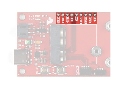
A (battery) fuel gauge and a Qwiic connector are attached to the primary I2C bus I2C1. The primary I2C bus for this board utilizes the GPIO connections, detailed in the table below:
|
Connection
| VDD | GND | SCL | SDA |
|---|
| Pin Number | 3.3V | GND |
Pin 9
Pin 35
| Pin 8 |
|---|
| GPIO | 3.3V | GND | GPIO 07
GPIO 23 | GPIO 06 |
|---|
I2C bus components on the SparkFun RP2040 Thing Plus. (Click to enlarge)
Note: The clock line of the I2C bus is tied between pins 9 and 35 (GPIO 07 and GPIO 23). This allows GPIO 23 - GPIO 26 to be aligned on the board's edge, for a consecutive, eight pin bus.
![Shared GPIO pin]()
Shared pin for GPIO 07 and GPIO 23 on the SparkFun RP2040 Thing Plus. (Click to enlarge)*Since the two GPIO pins are tied together, they cannot operate simultaneously.
Battery Fuel Gauge
The MAX17048 fuel gauge measures the approximate charge or discharge rate, state of charge (SOC) (based on ModelGauge algorithm), and voltage of a connected battery. Additionally, there is a configurable alert pin functionality for low SOC, 1% SOC, reset, overvoltage, or undervoltage. For more information, pleas refer to the MAX17048 datasheet.
![MAX17048 Fuel Gauge]() The MAX17048 fuel gauge on the SparkFun RP2040 Thing Plus. (Click to enlarge)
The MAX17048 fuel gauge on the SparkFun RP2040 Thing Plus. (Click to enlarge)| I2C Address | 0x36 (7-bit)
0x6C (write)/0x6D (read)
|
| Voltage Measurement |
Range: 2.5 - 5 V
Precision: ±7.5 mV/Cell
Resolution 1.25 mV/Cell
|
| Current Consumption |
Sleep: .5 - 2 µA
Hibernate: 3 - 5 µA
Active: 23 - 40 µA
|
| Alert Indicators: |
Low SOC
1% Change in SOC
Battery Undervoltage/Overvoltage
VRESET Alert
|
| Alert Pin | GPIO 24 |
Qwiic Connector
A Qwiic connector is provided for users to seamlessly integrate with SparkFun's Qwiic Ecosystem.
Qwiic connector on the SparkFun RP2040 Thing Plus. (Click to enlarge)
What is Qwiic?
The Qwiic system is intended a quick, hassle-free cabling/connector system for I2C devices. Qwiic is actually a play on words between "quick" and I2C or "iic".
Features of the Qwiic System
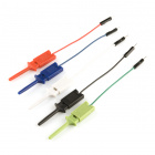
Keep your soldering iron at bay.
Cables plug easily between boards making quick work of setting up a new prototype. We currently offer three different lengths of Qwiic cables as well as a breadboard friendly cable to connect any Qwiic enabled board to anything else. Initially you may need to solder headers onto the shield to connect your platform to the Qwiic system but once that’s done it’s plug and go!
Minimize your mistakes.
How many times have you swapped the SDA and SCL wires on your breadboard hoping the sensor will start working? The Qwiic connector is polarized so you know you’ll have it wired correctly, every time, from the start.
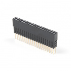
The PCB connector is part number SM04B-SRSS (Datasheet) or equivalent. The mating connector used on cables is part number SHR04V-S-B or equivalent. This is a common and low cost connector.
![JST Connector]()
1mm pitch, 4-pin JST connector
Expand with ease.
It’s time to leverage the power of the I2C bus! Most Qwiic boards will have two or more connectors on them allowing multiple devices to be connected.
I2C Jumper
Cutting the I2C jumper will remove the 4.7kΩ pull-up resistors from the I2C bus. If you have many devices on your I2C bus you may want to remove these jumpers.
I2C pull-up resistor jumper. (Click to enlarge)
Software Overview
Note: The information contained in this section will be expanded upon as more resources become available.
The Raspberry Pi foundation provides excellent documentation for programming the RP2040 using either MicroPython or C++. Users can find the online documentation resources here.
Pico C/C++ SDK
In order to program the RP2040, users will use the Pico C/C++ SDK (software development kit), provided by the Raspberry Pi Foundation. Additionally, the Raspberry Pi Foundation has written a user manual, which includes software documentation and examples to accompany the Pico C/C++ SDK.
Note: For novice programmers, we recommend starting off with the Getting Started with Raspberry Pi Pico guide, from the Raspberry Pi Foundation. While the guide is intended for their RP2040 microcontroller board, it contains useful information for getting started with the Pico C/C++ SDK, building and uploading a program, debugging, and adapting the SDK to a third-party IDE. The Raspberry Pi Foundation also provides an installation script to install and setup the Pico C/C++ SDK on a Raspberry Pi computer, which can be downloaded from their GitHub repository.
As documented in the user manual, the Pico C/C++ SDK can be used with various integrated development environments (IDEs). In order to utilize the SDK, users will also need to install a few dependencies. The Raspberry Pi Foundation also provides more C/C++ examples for all the basic functionalities of the RP2040 in their GitHub repository.
Note: Users programming with the Pico C/C++ SDK will be creating a project, compiling, and building their code to a .uf2 file, which the SDK generates. The .uf2 firmware file is then copied to the board, when it is in BOOTSEL mode to upload the program.
Pico Python SDK
The Raspberry Pi Foundation has also ported MicroPython to support the RP2040 microcontroller. Additionally, the Raspberry Pi Foundation has written a user manual, which includes documentation and examples for the Pico Python SDK.
Note: For novice programmers, we recommend starting off with the Get Started with MicroPython on Raspberry Pi Pico book, writtten by the Raspberry Pi Foundation. While the book is intended for their RP2040 microcontroller board, it contains useful information for getting started with MircoPython, utilizing the REPL (Read–Eval–Print Loop), and several projects.
As documented in the user manual, the Pico Python SDK can be used with various integrated development environments (IDEs). In order to utilize the SDK, users will also need to install a few dependencies. The Raspberry Pi Foundation also provides MicroPython examples to accompany the book (noted above), which can be downloaded from their GitHub repository.
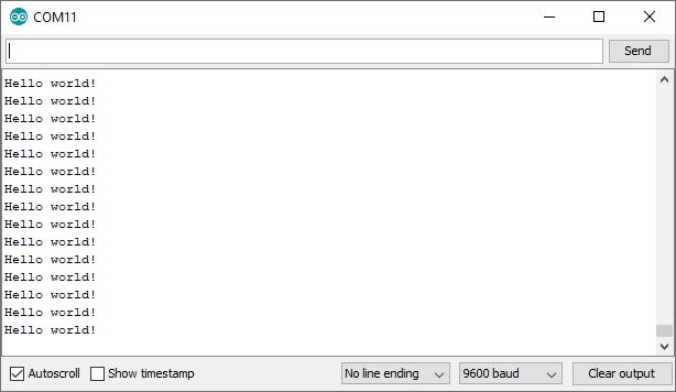
Read–Eval–Print Loop (REPL)
Users can access the REPL with their favorite serial terminal to instantly program the RP2040 microcontroller. After the MicroPython firmware is copied to the board, it will reset and show up on the computer's serial (or COM) port. Make sure to configure the serial terminal emulator for a baudrate of 115200 bps.
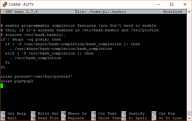
Remote MicroPython Shell on Windows 10: Below is an example of how to connect to a board using rshell on Windows 10:
- Install prerequisites
Install Remote MicroPython Shell (rshell)- In PowerShell (run as admin), type
pip3 install rshell
Open rshell- In PowerShell (run as admin), type
rshell
In the remote shell, connect to the COM port for the RP2040 Thing Plus- Type
connect serial COM[#] [baudrate] - To connect to
COM3: connect serial COM3 115200 - *Use the device manager to find the COM port for the RP2040 Thing Plus
Hardware Assembly
Note: The information contained in this section will be expanded upon as more resources become available.
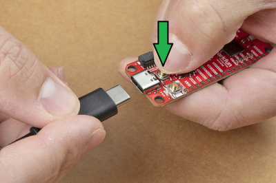
USB Programming
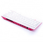
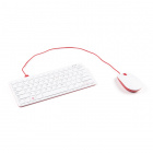
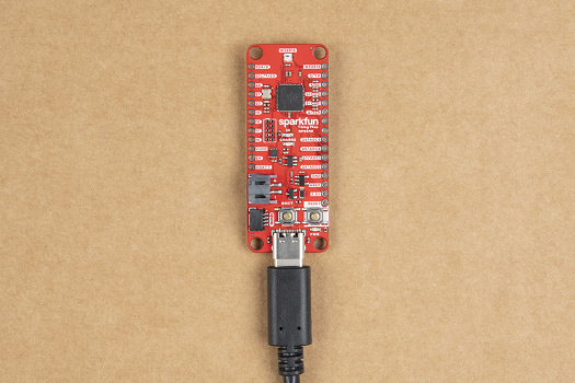
The USB connection is utilized for programming and serial communication. Users only need to plug their RP2040 Thing Plus into a computer using a USB-C cable.
The SparkFun Thing Plus - RP2040 attached to a computer. (Click to enlarge)
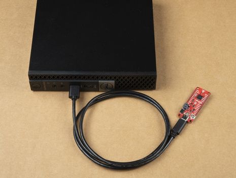
BOOTSEL Mode
Users can enter BOOTSEL mode by holding down the BOOT button, when the USB connection is made to a computer. The board will remain in this mode until it power cycles (happens automatically after uploading a .uf2 firmware file) or the RESET button is pressed. The board will appear as a USB mass storage device under the name RPI-RP2.
Hold down BOOT button to enter BOOTSEL mode on The SparkFun Thing Plus - RP2040. (Click to enlarge)
Battery
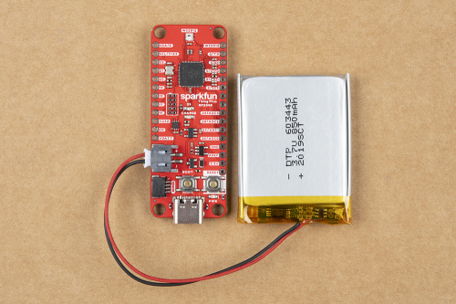
For remote applications, the RP2040 Thing Plus can be powered through its 2-pin JST battery connector.
The SparkFun Thing Plus - RP2040 with a battery attached. (Click to enlarge)
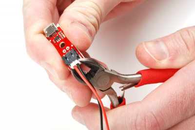
Note: DO NOT remove batteries by pulling on their wires. Instead, it is recommended that pair of dikes (i.e. diagonal wire cutters), pliers, or tweezers be used to pull on the JST connector housing, to avoid damaging the battery wiring.
![Disconnect battery w/ dikes]()
Using a pair of dikes to disconnect a battery. (Click to enlarge)MicroPython Examples
Note: The information contained in this section will be expanded upon as more resources become available.
Below, are some MicroPython examples that can be copied and pasted into the REPL.
LED Control
This example turns on the GPIO 25 status LED. Try changing the led.value() value to 0.
language:python
from machine import Pin
led = Pin(25, Pin.OUT)
led.value(1)

# Include blank carriage returns
WS2812 Control
This example controls the WS2812 RGB LED on the board. Try changing the r, g, and b values (range is 0 - 255).
language:python
# Example using PIO to drive a WS2812 LED
// Copy and paste directly into REPL from TeraTerm
// Make sure baudrate is set to 115200 bps

import array, time
from machine import Pin
import rp2

# Configure the number of WS2812 LEDs.
NUM_LEDS = 1


@rp2.asm_pio(sideset_init=rp2.PIO.OUT_LOW, out_shiftdir=rp2.PIO.SHIFT_LEFT, autopull=True, pull_thresh=24)
def ws2812():
T1 = 2
T2 = 5
T3 = 3
wrap_target()
label("bitloop")
out(x, 1)               .side(0)    [T3 - 1]
jmp(not_x, "do_zero")   .side(1)    [T1 - 1]
jmp("bitloop")          .side(1)    [T2 - 1]
label("do_zero")
nop()                   .side(0)    [T2 - 1]
wrap()


# Create the StateMachine with the ws2812 program, outputting on Pin(08).
sm = rp2.StateMachine(0, ws2812, freq=8_000_000, sideset_base=Pin(08))

# Start the StateMachine, it will wait for data on its FIFO.
sm.active(1)

# Display a pattern on the LEDs via an array of LED RGB values.
ar = array.array("I", [0 for _ in range(NUM_LEDS)])

# Cycle colours.
for i in range(4 * NUM_LEDS):
for j in range(NUM_LEDS):
r = 255
b = 255
g = 255
ar[j] = r << 16 | g << 8 | b
sm.put(ar, 8)


# Include blank carriage returns
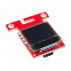
OLED Control
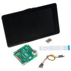
This example displays a bitmap and text on two OLED screens. For this example, users will need the Micro OLED Breakout (Qwiic), the Qwiic OLED Display, and a Qwiic cable kit. Users will need to upload a modified version of the MicroPython firmware, which includes the SSD1306 display driver.
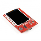
An example of the Thing Plus - RP2040 running with two OLED displays. (Click to enlarge)
language:python
# Display Image & text on I2C driven ssd1306 OLED display
from machine import Pin, I2C
from ssd1306 import SSD1306_I2C
import framebuf
WIDTH_1 = 64 # oled display width
HEIGHT_1 = 48 # oled display height
WIDTH_2 = 128 # oled display width
HEIGHT_2 = 32 # oled display height
i2c = I2C(1) # Init I2C using I2C0 defaults, SCL=Pin(GP9), SDA=Pin(GP8), freq=400000
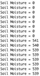
print("I2C Address : "+hex(i2c.scan()[0]).upper()) # Display device address
print("I2C Configuration: "+str(i2c)) # Display I2C config
oled1 = SSD1306_I2C(WIDTH_1, HEIGHT_1, i2c, addr=0x3D) # Init oled_1 display
# SparkFun logo as 32x48 bytearray
buffer[:] = [\
0x00, 0x00, 0x00, 0x00, 0x00, 0x00, 0x00, 0x00, 0x00, 0x00, 0x00, 0x00, 0x00, 0x00, 0x00, 0x00, \
0x00, 0x00, 0x00, 0x00, 0x00, 0x00, 0x00, 0x00, 0xE0, 0xF8, 0xFC, 0xFE, 0xFF, 0xFF, 0xFF, 0xFF, \
0xFF, 0xFF, 0xFF, 0x0F, 0x07, 0x07, 0x06, 0x06, 0x00, 0x80, 0x80, 0x00, 0x00, 0x00, 0x00, 0x00, \
0x00, 0x00, 0x00, 0x00, 0x00, 0x00, 0x00, 0x00, 0x00, 0x00, 0x00, 0x00, 0x00, 0x00, 0x00, 0x00, \
0x00, 0x00, 0x00, 0x00, 0x00, 0x00, 0x00, 0x00, 0x00, 0x00, 0x00, 0x00, 0x00, 0x00, 0x00, 0x00, \
0x00, 0x00, 0x80, 0x80, 0x80, 0x80, 0x80, 0x80, 0x81, 0x07, 0x0F, 0x3F, 0x3F, 0xFF, 0xFF, 0xFF, \
0xFF, 0xFF, 0xFF, 0xFF, 0xFE, 0xFE, 0xFC, 0xFC, 0xFC, 0xFE, 0xFF, 0xFF, 0xFF, 0xFC, 0xF8, 0xE0, \
0x00, 0x00, 0x00, 0x00, 0x00, 0x00, 0x00, 0x00, 0x00, 0x00, 0x00, 0x00, 0x00, 0x00, 0x00, 0x00, \
0x00, 0x00, 0x00, 0x00, 0x00, 0x00, 0x00, 0x00, 0x00, 0x00, 0x00, 0x00, 0x00, 0x00, 0x00, 0xFC, \
0xFE, 0xFF, 0xFF, 0xFF, 0xFF, 0xFF, 0xFF, 0xF1, 0xE0, 0xE0, 0xE0, 0xE0, 0xE0, 0xF0, 0xFD, 0xFF, \
0xFF, 0xFF, 0xFF, 0xFF, 0xFF, 0xFF, 0xFF, 0xFF, 0xFF, 0xFF, 0xFF, 0xFF, 0xFF, 0xFF, 0xFF, 0xFF, \
0x00, 0x00, 0x00, 0x00, 0x00, 0x00, 0x00, 0x00, 0x00, 0x00, 0x00, 0x00, 0x00, 0x00, 0x00, 0x00, \
0x00, 0x00, 0x00, 0x00, 0x00, 0x00, 0x00, 0x00, 0x00, 0x00, 0x00, 0x00, 0x00, 0x00, 0x00, 0xFF, \
0xFF, 0xFF, 0xFF, 0xFF, 0xFF, 0xFF, 0xFF, 0xFF, 0xFF, 0xFF, 0xFF, 0xFF, 0xFF, 0xFF, 0xFF, 0xFF, \
0xFF, 0xFF, 0xFF, 0xFF, 0xFF, 0xFF, 0xFF, 0xFF, 0xFF, 0xFF, 0xFF, 0x7F, 0x3F, 0x1F, 0x07, 0x01, \
0x00, 0x00, 0x00, 0x00, 0x00, 0x00, 0x00, 0x00, 0x00, 0x00, 0x00, 0x00, 0x00, 0x00, 0x00, 0x00, \
0x00, 0x00, 0x00, 0x00, 0x00, 0x00, 0x00, 0x00, 0x00, 0x00, 0x00, 0x00, 0x00, 0x00, 0x00, 0xFF, \
0xFF, 0xFF, 0xFF, 0xFF, 0xFF, 0xFF, 0xFF, 0xFF, 0x7F, 0x3F, 0x1F, 0x1F, 0x0F, 0x0F, 0x0F, 0x0F, \
0x0F, 0x0F, 0x0F, 0x0F, 0x07, 0x07, 0x07, 0x03, 0x03, 0x01, 0x00, 0x00, 0x00, 0x00, 0x00, 0x00, \
0x00, 0x00, 0x00, 0x00, 0x00, 0x00, 0x00, 0x00, 0x00, 0x00, 0x00, 0x00, 0x00, 0x00, 0x00, 0x00, \
0x00, 0x00, 0x00, 0x00, 0x00, 0x00, 0x00, 0x00, 0x00, 0x00, 0x00, 0x00, 0x00, 0x00, 0x00, 0xFF, \
0x7F, 0x3F, 0x1F, 0x0F, 0x07, 0x03, 0x01, 0x00, 0x00, 0x00, 0x00, 0x00, 0x00, 0x00, 0x00, 0x00, \
0x00, 0x00, 0x00, 0x00, 0x00, 0x00, 0x00, 0x00, 0x00, 0x00, 0x00, 0x00, 0x00, 0x00, 0x00, 0x00, \
0x00, 0x00, 0x00, 0x00, 0x00, 0x00, 0x00, 0x00, 0x00, 0x00, 0x00, 0x00, 0x00, 0x00, 0x00, 0x00]
# Load the SparkFUn logo into the framebuffer (the image is 32x48)
fb = framebuf.FrameBuffer(buffer, 64, 48, framebuf.MONO_VLSB)
# Clear the oled display in case it has junk on it.
oled1.fill(0)
# Blit the image from the framebuffer to the oled display
oled1.blit(fb, 0, 0)
# Finally update the oled display so the image & text is displayed
oled1.show()
oled2 = SSD1306_I2C(WIDTH_2, HEIGHT_2, i2c, addr=0x3C) # Init oled_2 display
# Clear the oled display in case it has junk on it.
oled2.fill(0)
# Add some text
oled2.text("SparkFun Thing",5,5)
oled2.text("Plus - RP2040",5,15)
oled2.text("(DEV-17745)",5,25)
oled2.show()
# Include blank carriage returns
Resources and Going Further
For more on the Artemis Development Kit, check out the links below:
- Schematic (PDF)
- Eagle Files (ZIP)
- Board Dimensions (PDF)
- Software (SDK) Documentation:
- Hardware Component Information:
- Software Development Platforms for the RP2040:
- Pico Python SDK - MicroPython (Ported)
- Pico C/C++ SDK
- Tools and Resources:
- UF2 Files- Just drag-and-drop onto your RP2040 board
- C/C++ Files:
- MicroPython Files:
- Utility Files:
learn.sparkfun.com |
CC BY-SA 3.0
| SparkFun Electronics | Niwot, Colorado